EP4486006A1 - Communication system and communication terminal - Google Patents
Communication system and communication terminal Download PDFInfo
- Publication number
- EP4486006A1 EP4486006A1 EP22928812.1A EP22928812A EP4486006A1 EP 4486006 A1 EP4486006 A1 EP 4486006A1 EP 22928812 A EP22928812 A EP 22928812A EP 4486006 A1 EP4486006 A1 EP 4486006A1
- Authority
- EP
- European Patent Office
- Prior art keywords
- base station
- communication
- information
- communication terminal
- control mode
- Prior art date
- Legal status (The legal status is an assumption and is not a legal conclusion. Google has not performed a legal analysis and makes no representation as to the accuracy of the status listed.)
- Pending
Links
Images






Classifications
-
- H—ELECTRICITY
- H04—ELECTRIC COMMUNICATION TECHNIQUE
- H04W—WIRELESS COMMUNICATION NETWORKS
- H04W4/00—Services specially adapted for wireless communication networks; Facilities therefor
- H04W4/70—Services for machine-to-machine communication [M2M] or machine type communication [MTC]
-
- G—PHYSICS
- G05—CONTROLLING; REGULATING
- G05D—SYSTEMS FOR CONTROLLING OR REGULATING NON-ELECTRIC VARIABLES
- G05D1/00—Control of position, course, altitude or attitude of land, water, air or space vehicles, e.g. using automatic pilots
- G05D1/20—Control system inputs
- G05D1/22—Command input arrangements
- G05D1/221—Remote-control arrangements
- G05D1/226—Communication links with the remote-control arrangements
-
- G—PHYSICS
- G05—CONTROLLING; REGULATING
- G05D—SYSTEMS FOR CONTROLLING OR REGULATING NON-ELECTRIC VARIABLES
- G05D1/00—Control of position, course, altitude or attitude of land, water, air or space vehicles, e.g. using automatic pilots
- G05D1/60—Intended control result
- G05D1/69—Coordinated control of the position or course of two or more vehicles
- G05D1/698—Control allocation
- G05D1/6987—Control allocation by centralised control off-board any of the vehicles
-
- G—PHYSICS
- G05—CONTROLLING; REGULATING
- G05D—SYSTEMS FOR CONTROLLING OR REGULATING NON-ELECTRIC VARIABLES
- G05D2105/00—Specific applications of the controlled vehicles
- G05D2105/45—Specific applications of the controlled vehicles for manufacturing, maintenance or repairing
-
- G—PHYSICS
- G05—CONTROLLING; REGULATING
- G05D—SYSTEMS FOR CONTROLLING OR REGULATING NON-ELECTRIC VARIABLES
- G05D2107/00—Specific environments of the controlled vehicles
- G05D2107/70—Industrial sites, e.g. warehouses or factories
-
- G—PHYSICS
- G05—CONTROLLING; REGULATING
- G05D—SYSTEMS FOR CONTROLLING OR REGULATING NON-ELECTRIC VARIABLES
- G05D2109/00—Types of controlled vehicles
- G05D2109/10—Land vehicles
-
- H—ELECTRICITY
- H04—ELECTRIC COMMUNICATION TECHNIQUE
- H04W—WIRELESS COMMUNICATION NETWORKS
- H04W36/00—Hand-off or reselection arrangements
- H04W36/08—Reselecting an access point
Definitions
- the present disclosure relates to a communication system and a communication terminal.
- Patent Document 1 discloses a system including a robot, a machining device, a robot controller that controls the robot, a machining device controller that controls the machining device, and a programmable logic controller that generates commands for the robot controller and the machining device controller.
- Patent Document 1 Japanese Unexamined Patent Publication No. 2019-209454
- the present disclosure provides a communication system effective for improving reliability of inter-device communication by mobile wireless communication.
- a communication system includes: a host system including a client device and a server device configured to perform inter-device communication with the client device; and a communication terminal connected to the client device and configured to perform mobile wireless communication for inter-device communication with a base station connected to the server device, wherein the communication terminal is configured to notify the host system of information of the base station.
- a communication terminal is a communication terminal that is connected to a client device of a host system including the client device and a server device that are configured to perform inter-device communication with each other, the communication terminal being configured to perform mobile wireless communication for the inter-device communication with a base station connected to the server device, the communication terminal including: a base station information acquisition unit configured to acquire information of the base station; and a notification unit configured to notify a system of information of the base station.
- FIG. 1 is a schematic view illustrating a machine system.
- a machine system 1 illustrated in FIG. 1 includes a server device 100 and a plurality of machines 20. Each of the plurality of machines 20 performs motions. Although three machines 20 are illustrated in FIG. 1 , the number of the machines 20 is not limited to this.
- Each of the plurality of machines 20 includes a body 30 and a local controller 300.
- the body 30 is a machine that is controlled by the local controller 300 and performs multiple types of motion.
- the type of the body 30 is not particularly limited.
- the body 30A is a mobile robot, and performs motions for conveying, processing, assembling, and the like on a workpiece.
- Specific examples of the motions include a motion for conveying a component and attaching the component to a workpiece, a motion for conveying a tool such as a screw tightening tool or a welding torch and processing the workpiece, and a motion for conveying the workpiece itself.
- the body 30 includes an automated guided vehicle 31 and a robot 40.
- the automated guided vehicle 31 supports and moves the robot 40.
- the robot 40 is, for example, a vertical articulated industrial robot.
- the robot 40 includes a base 41, a pivoting portion 42, a first arm 43, a second arm 44, a wrist portion 45, and a tip portion 46.
- the base 41 is placed on top of the automated guided vehicle 31.
- the pivoting portion 42 is mounted on the base 41 so as to be rotatable about a vertical axis 51.
- the robot 40 includes a joint 61 that attaches the pivoting portion 42 to the base 41 so as to be rotatable about the axis 51.
- the first arm 43 is connected to the pivoting portion 42 so as to be rotatable about an axis 52 intersecting (for example, orthogonal to) the axis 51.
- the robot 40 includes a joint 62 that connects the first arm 43 to the pivoting portion 42 so as to be rotatable about the axis 52. Intersecting includes being skewed, such as so-called grade separation. The same applies to the following.
- the first arm 43 extends from the pivoting portion 42 along a direction that intersects (for example, is orthogonal to) the axis 52.
- the second arm 44 is connected to the end of the first arm 43 so as to be rotatable about an axis 53 parallel to the axis 52.
- the robot 40 includes a joint 63 that connects the second arm 44 to the first arm 43 so as to be rotatable about the axis 53.
- the second arm 44 includes an arm base 47 that extends from the end of the first arm 43 along one direction that intersects (for example, is orthogonal to) the axis 53, and an arm end 48 that further extends from the end of the arm base 47 along the same one direction.
- the arm end 48 is rotatable about an axis 54 relative to the arm base 47.
- the axis 54 intersects (for example, is orthogonal to) the axis 53.
- the robot 40 includes a joint 64 that connects the arm end 48 to the arm base 47 so as to be rotatable about the axis 54.
- the wrist portion 45 is connected to the arm end 48 so as to be rotatable about an axis 55 that intersects (for example, is orthogonal to) the axis 54.
- the robot 40 includes a joint 65 that connects the wrist portion 45 to the arm end 48 so as to be rotatable about the axis 55.
- the wrist portion 45 extends from the end of the arm end 48 along one direction that intersects (for example, is orthogonal to) the axis 55.
- the tip portion 46 is connected to the end of the wrist portion 45 so as to be rotatable about an axis 56 that intersects (for example, is orthogonal to) the axis 55.
- the robot 40 includes a joint 66 that connects the tip portion 46 to the wrist portion 45 so as to be rotatable about the axis 56.
- An end effector is provided on the tip portion 46.
- Specific examples of the end effector include a hand that grips a workpiece, and a work tool that performs processing, assembly, or the like on a workpiece.
- Actuators 71, 72, 73, 74, 75, 76 drive the joints 61, 62, 63, 64, 65, 66.
- Each of the actuators 71, 72, 73, 74, 75, 76 includes, for example, an electric motor and a transmission unit (for example, a reduction gear) that transmits the power of the electric motor to the joints 61, 62, 63, 64, 65, 66.
- the actuator 71 drives the joint 61 so as to rotate the pivoting portion 42 about the axis 51.
- the actuator 72 drives the joint 62 so as to rotate the first arm 43 about the axis 52.
- the actuator 73 drives the joint 63 so as to rotate the second arm 44 about the axis 53.
- the actuator 74 drives the joint 64 so as to rotate the arm end 48 about the axis 54.
- the actuator 75 drives the joint 65 so as to rotate the wrist portion 45 about the axis 55.
- the actuator 76 drives the joint 66 so as to rotate the tip portion 46 about the axis 56.
- the body 30 is not necessarily limited to the above-described mobile robot, and may be a robot fixed at a fixed position.
- the body 30 may be an automated guided vehicle that performs a motion for conveying a conveyance object such as a workpiece.
- the body 30B is an automated guided vehicle that conveys a conveyance object such as a workpiece.
- the body 30B includes an automated guided vehicle 33 and a loading table 34.
- the automated guided vehicle 33 supports and moves the loading table 34.
- the loading table 34 supports the conveyance object.
- the server device 100 performs inter-device communication with the local controller 300 of the plurality of machines 20, and causes the bodies 30 of the plurality of machines 20 to perform a series of motions for production of a workpiece or the like.
- the machine system 1 includes a communication system 10.
- the communication system 10 includes a host system 11 and a communication terminal 400.
- the host system 11 includes the machine 20 that is an example of a client device, and the server device 100 that performs inter-device communication with the client device.
- the inter-device communication is communication performed between devices to control motion, for example, as described above.
- Such inter-device communication may include transmission and reception of control commands, transmission and reception of feedback information during control, transmission and reception of operation completion notifications in response to a control command, and the like.
- the communication terminal 400 is connected to the local controller 300 and performs mobile wireless communication for inter-device communication with a base station 200 connected to the server device 100.
- Examples of the mobile wireless communication include, but are not necessarily limited to, communication using a fifth-generation mobile communication system (5G communication).
- 5G communication fifth-generation mobile communication system
- the communication terminal 400 is fixed to the body 30 and moves together with the body 30. Accordingly, the communication terminal 400 can be moved by the local controller 300.
- a plurality of base stations 200 may be connected to the server device 100.
- a connection state between the communication terminal 400 and the plurality of base stations 200 may have an influence on reliability of inter-device communication. For example, there is a possibility that mobile wireless communication satisfying a requirement for the inter-device communication cannot be performed depending on specifications of the base station 200 to which the communication terminal 400 is connected because the specifications of the plurality of base stations 200 are different from each other. For example, in the base station 200 whose communication speed is low, there is a possibility that inter-device communication cannot be performed at a sufficiently high speed.
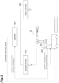
- the communication terminal 400 is configured to notify the host system 11 of information of the base station 200. Accordingly, in the host system 11, it is possible to cope with the above-described influence based on the information of the base station 200. Examples of coping with the above-described influence include changing the control mode of the body 30 by the server device 100, as illustrated in FIG. 3 .
- the communication terminal 400 may notify the local controller 300 of the information of the base station 200, may notify the server device 100 of the information of the base station 200, or may notify both the local controller 300 and the server device 100 of the information of the base station 200.
- Notifying the server device 100 of the information of the base station 200 includes notifying the local controller 300 of the information of the base station 200 and causing the local controller 300 to transmit the information of the base station 200 to the server device 100.
- the information of the base station 200 may include both information of the base station 200 that is connected and information of the base station 200 that is not connected.
- the information of the base station 200 includes, for example, identification information of the base station 200.
- the identification information of the base station 200 may be, for example, information that can identify the individual base station 200 or information that can identify attributes of the base station 200. Examples of the information that can identify the attributes of the base station 200 include information indicating the type of the base station 200 and information indicating the specifications of the base station 200.
- the information of the base station 200 may include information of a communication state between the local controller 300 and the communication terminal 400.
- Examples of the information of the communication state include information on radio waves received from the base station 200 (for example, information on the strength of radio waves), information indicating a sign of handover from a connected base station 200 to another base station 200, and the like.
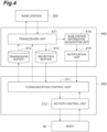
- FIG. 4 is a block diagram illustrating a functional configuration of the communication terminal 400 and the local controller 300.
- the communication terminal 400 includes a transceiver unit 411, a transmission buffer 412, a reception buffer 413, a base station information acquisition unit 414, and a notification unit 415 as functional constituent elements (hereinafter referred to as "functional blocks").
- the transceiver unit 411 performs mobile wireless communication with the base station 200.
- the transmission buffer 412 temporarily stores information that the transceiver unit 411 transmits to the base station 200 through mobile wireless communication.
- the reception buffer 413 temporarily stores information received by the transceiver unit 411 from the base station 200 through mobile wireless communication.
- the base station information acquisition unit 414 acquires the information of the base station 200 from the information that the transceiver unit 411 received from the base station 200.
- the notification unit 415 notifies the local controller 300 of the information of the base station 200.
- the local controller 300 includes a communication control unit 311 and a motion control unit 312 as functional blocks.
- the communication control unit 311 performs inter-device communication with the server device 100.
- the communication control unit 311 stores, in the transmission buffer 412, information to be transmitted from the communication terminal 400 to the base station 200, and reads, from the reception buffer 413, information that the communication terminal 400 receives from the base station 200.
- the motion control unit 312 controls the body 30 based on the control command received by the communication control unit 311 from the server device 100.
- the motion control unit 312 may be configured to autonomously perform at least a part of the control of the body 30 without being based on the control command from the server device 100.
- the local controller 300 controls the body 30 based on, for example, an operation program stored therein.
- the operation program includes a plurality of operation commands arranged in time series. Each of the plurality of operation commands includes an operation target position and an operation target speed of the body 30. Examples of the operation target position of the body 30 include an operation target position of the tip portion 46.
- the operation target position of the tip portion 46 includes an operation target posture of the tip portion 46.
- the communication control unit 311 receives notification of the information of the base station 200 from the notification unit 415.
- the communication control unit 311 may store the information of the base station 200 in the transmission buffer 412 and cause the communication terminal 400 to transmit the information to the base station 200.
- the information of the base station 200 is also notified to the server device 100.
- the communication terminal 400 may be configured to notify the server device 100 of the information of the base station 200 without going through the local controller 300.
- the notification unit 415 may store the information of the base station 200 in the transmission buffer 412 and cause the communication terminal 400 to transmit the information to the base station 200.
- the communication control unit 311 may control the communication terminal 400 to be connected to the base station 200 that is predetermined (default base station). For example, the communication control unit 311 designates the default base station and requests the transceiver unit 411 to limit the connection destination so as to be preferentially connected to the default base station.
- the transceiver unit 411 controls a transmission/reception direction of a radio signal by beam forming or the like so as to be easily connected to the default base station.
- the communication control unit 311 may request the transceiver unit 411 to connect to the base station 200 (including reconnection) after moving the body 30 using the motion control unit 312 so that the communication terminal 400 approaches the default base station.
- the communication control unit 311 may execute both moving the body 30 using the motion control unit 312 so that the communication terminal 400 approaches the default base station, and controlling the transceiver unit 411 to be preferentially connected to the default base station.
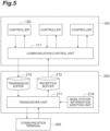
- FIG. 5 is a block diagram illustrating a functional configuration of the base station 200 and the server device 100.
- the base station 200 includes a transceiver unit 211, a transmission buffer 212, a reception buffer 213, and a base station information addition unit 214 as functional blocks.
- the transceiver unit 211 performs mobile wireless communication with the communication terminal 400.
- the transmission buffer 212 temporarily stores information that the transceiver unit 211 transmits to the communication terminal 400 through mobile wireless communication.
- the reception buffer 213 temporarily stores information received by the transceiver unit 211 from the communication terminal 400 through mobile wireless communication.
- the base station information addition unit 214 adds the above-described information of the base station 200 to the information that the transceiver unit 211 transmits to the communication terminal 400.
- the server device 100 includes a communication control unit 111 and a plurality of controllers 120 as functional blocks.
- the communication control unit 111 performs inter-device communication with the local controller 300.
- the communication control unit 111 stores, in the transmission buffer 212, information to be transmitted from the base station 200 to the communication terminal 400, and reads, from the reception buffer 213, information that the base station 200 receives from the communication terminal 400.
- the communication control unit 111 receives the information of the base station 200. As a result, the communication control unit 111 is notified of the information of the base station 200. Instead of the communication control unit 311, the communication control unit 111 may control the communication terminal 400 to be connected to the default base station. For example, the communication control unit 111 stores a request for restriction of a connection destination by beam forming or the like in the transmission buffer 212.
- the communication control unit 111 may request the transceiver unit 411 to connect to the base station 200 (including reconnection) after moving the body 30 using the motion control unit 312 so that the communication terminal 400 approaches the default base station.
- the communication control unit 111 stores, in the transmission buffer 212, a command to move the body 30 using the motion control unit 312 so that the communication terminal 400 approaches the default base station, and stores, in the transmission buffer 212, a request to connect to the base station 200 for the transceiver unit 411 after reading a completion notification of the movement of the body 30 from the reception buffer 213.
- Each of the plurality of controllers 120 controls each of the plurality of machines 20 through inter-device communication performed by the communication control unit 111.
- each of the plurality of controllers 120 includes an information reception unit 121, a command calculation unit 122, a command transmission unit 123, a mode change unit 124, and a sign detection unit 125 as functional blocks.
- the information reception unit 121 receives feedback information indicating a state of a corresponding machine 20 through inter-device communication.
- the feedback information include information indicating the current position and posture of the body 30.
- the current position and posture of the body 30 include the current position and posture of the automated guided vehicle 31 in the body 30A and the current position and posture of the robot 40 in the automated guided vehicle 31.
- the information indicating the current position and posture of the robot 40 may be the current angles of the joints 61, 62, 63, 64, 65, 66.
- the feedback information may be status information indicating whether the operation based on the command from the server device 100 is completed.
- the command calculation unit 122 calculates a motion command based on the feedback information.
- the motion command is a command to cause the local controller 300 to cause the body 30 to perform a motion.
- Examples of the motion command include a speed command or a force (torque) command for causing the current position and posture of the body 30 to follow the target position and posture.
- the motion command may be a start command of a predetermined series of operations.
- the command transmission unit 123 transmits the motion command to the local controller 300 of the corresponding machine 20 through inter-device communication.
- the mode change unit 124 changes the control mode of the machine 20 by the controller 120 based on the information of the base station 200. For example, the mode change unit 124 changes the control mode of the machine 20 by the controller 120 from one of a plurality of predetermined modes to another.
- the mode change unit 124 may change the control mode to reduce the influence of which controller 120 the communication terminal 400 is connected to.
- the plurality of control modes may include a server control mode and an autonomous control mode.
- the server control mode is a mode in which the controller 120 controls the motion of the body 30 through inter-device communication.
- the autonomous control mode is a mode in which the local controller 300 autonomously controls the motion of the body 30. In this case, for example, the controller 120 transmits a motion start command to the local controller 300 and receives a motion completion notification from the local controller 300.
- the frequency of inter-device communication is lower than in the server control mode. Accordingly, in the autonomous control mode, the influence of which the controller 120 the communication terminal 400 is connected to is smaller than that in the server control mode.
- Examples of the server control mode include a mode in which the motion of the body 30 is feedback-controlled by the server device 100.
- the controller 120 repeatedly executes reception of the feedback information by the information reception unit 121, generation of the motion command by the command calculation unit 122, and transmission of the motion command by the command transmission unit 123 at a predetermined control cycle.
- the information reception unit 121 receives feedback information indicating the current position and posture of the body 30.
- the command calculation unit 122 calculates a target position and posture for each control cycle based on a predetermined operation program, and calculates a motion command so that the current position and posture of the body 30 match the target position and posture.
- Making the current position and posture of the body 30 follow the target position and posture means changing the current position and posture in accordance with the change of the target position and posture so that the deviation between the target position and posture and the current position and posture remains within a predetermined range.
- the command calculation unit 122 calculates the motion command by performing a proportional operation, a proportional-integral operation, a proportional-integral-differential operation, or the like on the deviation between the target position and posture and the current position and posture.
- the command transmission unit 123 may add first cycle information designating a control cycle in which the motion command is to be read to the motion command and transmit the motion command to the local controller 300.
- the communication control unit 311 stores the received motion command until the control cycle designated by the first cycle information, and the motion control unit 312 reads the motion command in the control cycle and controls the body 30 based on the read motion command.
- the communication control unit 311 in the local controller 300 may add second cycle information designating the control cycle in which the feedback information is to be read to the feedback information and transmit the feedback information to the server device 100.
- the communication control unit 111 stores the feedback information until the control cycle designated by the second cycle information
- the information reception unit 121 reads the feedback information in the control cycle
- the command calculation unit 122 generates the motion command based on the read feedback information. Accordingly, the influence of the variation in the reception timing of the feedback information and the motion command on the motion of the body 30 is suppressed.
- a predetermined condition may be required for the capability of the base station 200.
- the base station 200 satisfying a predetermined condition is set as the above-described default base station.
- the mode change unit 124 sets the control mode of the machine 20 to the server control mode if it determines that the base station 200 (the base station 200 to which the communication terminal 400 is connected) is the default base station based on the information of the base station 200, and sets the control mode of the machine 20 to the autonomous control mode if it determines that the base station 200 is not the default base station.
- the mode change unit 124 changes the server control mode to the autonomous control mode.
- the mode change unit 124 changes the autonomous control mode to the server control mode if it is determined that the state is switched from a state in which the base station 200 is not the default base station to a state in which the base station 200 is the default base station (handover from another base station to the default base station has occurred).
- the plurality of control modes may include a stop mode for keeping the body 30 in a stopped state.
- the mode change unit 124 may set the control mode of the machine 20 to the server control mode if it is determined that the base station 200 is the default base station based on the information of the base station 200, and may set the control mode of the machine 20 to the stop mode if it is determined that the base station 200 is not the default base station.
- the mode change unit 124 changes the control mode of the machine 20 from the server control mode to the stop mode if it is determined that the state is changed from a state in which the base station 200 is the default base station to a state in which the base station 200 is not the default base station (handover from the default base station to another base station occurs).
- the mode change unit 124 changes the control mode of the machine 20 from the stop mode to the server control mode if it is determined that the state is changed from a state in which the base station 200 is not the default base station to a state in which the base station 200 is the default base station (handover from another base station to the default base station occurs).
- the mode change unit 124 may change the control mode so that the communication terminal 400 is more easily connected to the default base station.
- the plurality of control modes may include a first control mode in which the movement range of the body 30 reaches a position farther than a predetermined reference distance from the default base station, and a second control mode in which the movement range of the body 30 falls within the reference distance from the default base station.
- the second control mode may be a mode in which the body 30 is operated at a fixed position.
- the second control mode may be a mode in which the robot 40 is operated with the automated guided vehicle 31 located at a fixed position.
- the body 30 operates at a position closer to the default base station than in the first control mode. Accordingly, in the second control mode, the communication terminal 400 is more easily connected to the default base station as compared with the first control mode. For example, if it is determined that the base station 200 is not the default base station based on the information of the base station 200 while the mode change unit 124 is controlling the machine 20 in the first control mode, the mode change unit 124 changes the control mode of the machine 20 from the first control mode to the second control mode.
- the sign detection unit 125 detects the sign of handover of the base station 200 based on the information of the base station 200. For example, the sign detection unit 125 detects the sign of handover based on information of radio waves received by the communication terminal 400 from the base station 200. For example, the sign detection unit 125 detects the sign of handover when the strength of radio waves received by the communication terminal 400 from the base station 200 falls below a predetermined reference strength.
- the information on the base station 200 may further include information on whether the communication terminal 400 receives an instruction to connect to a base station 200 other than the base station 200 being connected (hereinafter referred to as "handover instruction").
- the sign detection unit 125 may detect the sign of handover when the communication terminal 400 is receiving the handover instruction.
- the sign detection unit 125 may detect the sign of handover based on both whether the communication terminal 400 receives the handover instruction and the information of the radio waves received by the communication terminal 400 from the base station 200. For example, the sign detection unit 125 may detect a sign of handover when the communication terminal 400 receives a handover instruction and the strength of radio waves received by the communication terminal 400 from the base station 200 falls below a reference strength.
- the communication terminal 400 may be configured to detect the sign of handover, and may be configured to notify the host system 11 of a detection result of the sign of handover by including the detection result in the information of the base station 200.
- the sign detection unit 125 detects the sign of handover based on the detection result of the sign of handover by the communication terminal 400.
- the mode change unit 124 may change the control mode based on the sign of handover if the sign detection unit 125 detects the sign of handover.
- the mode change unit 124 may change the control mode based on the sign of handover so as to reduce the influence of the handover. For example, the mode change unit 124 may change the server control mode to the autonomous control mode or the stop mode if the sign detection unit 125 detects a sign of handover during execution of the server control mode. After switching the server control mode to the autonomous control mode or the stop mode, the mode change unit 124 may change the autonomous control mode to the server control mode if the sign detection unit 125 does not detect the sign of handover due to the completion of the handover or the like.
- the mode change unit 124 may change the control mode based on the sign of handover so as to reduce the sign of handover.
- the plurality of control modes may include a first control mode in which the movement range of the body 30 reaches a position farther than a predetermined reference distance from the connected base station, and a second control mode in which the movement range of the body 30 falls within the reference distance from the connected base station.
- the second control mode may be a mode in which the body 30 is operated at a fixed position.
- the body 30 operates at a position closer to the connected base station as compared with the first control mode. Accordingly, in the second control mode, the sign of handover is reduced compared to the first control mode.
- the mode change unit 124 changes the control mode of the machine 20 from the first control mode to the second control mode if a sign of handover is detected by the sign detection unit 125 while the machine 20 is controlled in the first control mode.
- the communication control unit 111 may control the communication terminal 400 to decrease the sign of handover if the sign of handover is detected by the sign detection unit 125.
- the communication control unit 111 designates the base station 200 being connected so as to reduce the sign of handover, and stores a request for restriction of a connection destination in the transmission buffer 212.
- the transceiver unit 411 controls the transmission/reception direction of a radio signal by beam forming or the like so as to reduce the sign of handover.
- FIG. 7 is a block diagram illustrating a hardware configuration of the server device 100 and the base station 200.
- the server device 100 includes circuitry 190.
- the circuitry 190 includes a processor 191, a memory 192, storage 193, and a user interface 195.
- the storage 193 is a nonvolatile storage medium. Specific examples of the storage 193 include a hard disk and a flash memory.
- the storage 193 may be a portable storage media such as an optical disc.
- the storage 193 stores a program for configuring the above-described functional blocks in the server device 100.
- the memory 192 is a temporary memory such as a random-access memory, and temporarily stores the program that is loaded from the storage 193.
- the processor 191 is configured by one or more arithmetic elements, and causes the server device 100 to configure each of the functional blocks by executing the program loaded in the memory 192.
- a communication port 194 communicates with the base station 200 in response to a request from the processor 191.
- the base station 200 includes circuitry 290.
- the circuitry 290 includes a processor 291, a memory 292, storage 293, a communication port 294, and an antenna 295.
- the storage 293 is a nonvolatile storage medium. Specific examples of the storage 293 include a hard disk and a flash memory.
- the storage 293 may be a portable storage media such as an optical disc.
- the storage 293 stores a program for configuring the above-described functional blocks in the base station 200.
- the memory 292 is a temporary memory such as a random-access memory, and temporarily stores the program that is loaded from the storage 293.
- the processor 291 is configured by one or more arithmetic elements, and causes the base station 200 to configure each of the functional blocks by executing the program loaded in the memory 292.
- the communication port 294 communicates with the communication port 194 in response to a request from the processor 291.
- the antenna 295 transmits and receives a signal for mobile wireless communication in response to a request from the processor 291.
- FIG. 8 is a block diagram illustrating a hardware configuration of the local controller 300 and the communication terminal 400.
- the local controller 300 includes circuitry 390.
- the circuitry 390 includes a processor 391, a memory 392, storage 393, a communication port 394, and drive circuitry 395.
- the storage 393 is a nonvolatile storage medium. Specific examples of the storage 393 include a hard disk and a flash memory. The storage 393 may be a portable storage media such as an optical disc. The storage 393 stores a program for configuring the above-described functional blocks in the local controller 300.
- the memory 392 is a temporary memory such as a random-access memory, and temporarily stores the program that is loaded from the storage 393.
- the processor 391 is configured by one or more arithmetic elements, and causes the local controller 300 to configure each of the functional blocks by executing the program loaded in the memory 392.
- the communication port 394 communicates with the communication terminal 400 in response to a request from the processor 391.
- the drive circuitry 395 outputs driving power to the body 30 in response to a request from the processor 391, and acquires feedback information from the body 30.
- the communication terminal 400 includes circuitry 490.
- the circuitry 490 includes a processor 491, a memory 492, storage 493, a communication port 494, and an antenna 495.
- the storage 493 is a nonvolatile storage medium. Specific examples of the storage 493 include a hard disk and a flash memory.
- the storage 493 may be a portable storage media such as an optical disc.
- the storage 493 stores a program for configuring the above-described functional blocks in the communication terminal 400.
- the memory 492 is a temporary memory such as a random-access memory, and temporarily stores the program that is loaded from the storage 493.
- the processor 491 is configured by one or more arithmetic elements, and causes the communication terminal 400 to configure each of the functional blocks by executing the program loaded in the memory 492.
- the communication port 494 communicates with the communication port 394 in response to a request from the processor 491.
- the antenna 495 transmits and receives a signal for mobile wireless communication in response to a request from the processor 491.
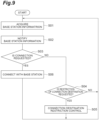
- This control procedure includes a connection procedure between the communication terminal 400 and the base station 200, a control procedure of the communication terminal 400 by the host system 11, a change procedure of the control mode based on information of the base station 200, a change procedure of the control mode based on the sign of handover, a control procedure by server control mode, and a control procedure by autonomous control mode.
- Each procedure will be described below.
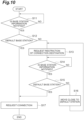
- the communication terminal 400 first executes steps S01, S02.
- the base station information acquisition unit 414 acquires information of the base station 200.
- the notification unit 415 notifies the local controller 300 of the information of the base station 200.
- the communication terminal 400 then executes a step S03.
- the transceiver unit 411 checks whether a request for connection to the base station 200 is received from the local controller 300. If it is determined in the step S03 that the request for connection is not received, the communication terminal 400 executes a step S04.
- the transceiver unit 411 checks whether a request for restricting connection destination restriction (for example, the above-described request for beam forming or the like) is received from the local controller 300. If it is determined in the step S04 that the request for restricting the connection destination is not received, the communication terminal 400 returns the process to the step S01.
- a request for restricting connection destination restriction for example, the above-described request for beam forming or the like
- the communication terminal 400 executes a step S05.
- the transceiver unit 411 controls the transmission/reception direction of a wireless signal so that the transceiver unit 411 can be easily connected to the base station 200 designated in the request for restriction of a connection destination.
- the communication terminal 400 executes a step S06.
- the transceiver unit 411 establishes a connection with the base station 200.
- the procedure described below can be executed by either the server device 100 or the local controller 300 in a state where a connection is established between the base station 200 and the communication terminal 400. It is assumed that the connection between the base station 200 and the communication terminal 400 is not established, and the following procedure is executed by the local controller 300.
- the local controller 300 first executes steps S 11, S12.
- the communication control unit 311 waits for the notification of information of the base station 200 from the notification unit 415.
- the communication control unit 311 waits for notification from the notification unit 415 of information of the base station 200 to which the communication terminal 400 can connect.
- the base station 200 to which the communication terminal 400 can be connected is referred to as a "candidate base station 200".
- the communication control unit 311 checks whether the candidate base station 200 is the default base station based on the information of the candidate base station 200. If it is determined in the step S12 that the candidate base station 200 is not the default base station, the communication control unit 311 executes steps S13, S14, S15.
- the communication control unit 311 designates the default base station and requests the transceiver unit 411 to restrict the connection destination. In response to this, the transceiver unit 411 controls the transmission/reception direction of the radio signal so as to facilitate connection to the default base station (the step S05 described above).
- the communication control unit 311 waits for the information of the candidate base station 200 to be notified again from the notification unit 415.
- the communication control unit 311 checks whether the candidate base station 200 is the default base station based on the information of the candidate base station 200.
- the local controller 300 executes a step S16.
- the communication control unit 311 moves the body 30 with the motion control unit 312 so that the communication terminal 400 approaches the default base station.
- the local controller 300 then returns the process to the step S13.
- the local controller 300 executes a step S 17.
- the communication control unit 311 requests the transceiver unit 411 to connect with the base station 200.
- the transceiver unit 411 establishes a connection with the base station 200 (the step S06 described above).
- the control procedure of the communication terminal 400 is completed.
- the server device 100 first executes steps S21, S22.
- the communication control unit 111 waits for the notification of the information of the base station 200 from the notification unit 415.
- the communication control unit 111 checks whether the connection between the communication terminal 400 and the base station 200 is maintained based on the information of the base station 200 notified from the notification unit 415. If it is determined in the step S22 that the connection between the communication terminal 400 and the base station 200 is maintained, the server device 100 executes a step S23. In the step S23, based on the information of the base station 200 acquired by the communication control unit 111, the mode change unit 124 checks whether the base station 200 is the default base station.
- the server device 100 executes a step S24.
- the mode change unit 124 sets the control mode to the server control mode described above.
- the server device 100 executes a step S25.
- the mode change unit 124 sets the control mode to the autonomous control mode described above.
- the server device 100 returns the process to the step S21. Until it is determined that the connection between the communication terminal 400 and the base station 200 is not maintained in the step S22, the server device 100 repeatedly executes the above processing. If it is determined in the step S22 that the connection between the communication terminal 400 and the base station 200 is not maintained, the server device 100 ends the process. Thereafter, for example, the procedure illustrated in FIG. 10 is executed again.
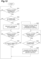
- the server device 100 first executes a step S31.
- the communication control unit 111 waits for the communication control unit 111 to be notified of the information of the base station 200 from the notification unit 415.
- the server device 100 then executes a step S32.
- the sign detection unit 125 checks whether there is a sign of handover of the base station 200 based on the information of the base station 200. If it is determined in the step S32 that there is no sign of handover, the server device 100 returns the process to the step S31.
- the server device 100 executes a step S33.
- the communication control unit 111 designates the base station 200 being connected so as to reduce the sign of handover, and stores a request for restriction of a connection destination in the transmission buffer 212.
- the transceiver unit 411 controls the transmission/reception direction of a radio signal by beam forming or the like so as to reduce the sign of handover.
- the server device 100 then executes a step S34.
- the communication control unit 111 waits for the communication control unit 111 to be notified of the information of the base station 200 from the notification unit 415.
- the sign detection unit 125 checks whether the sign of handover of the base station 200 is resolved based on the information of the base station 200.
- the server device 100 executes steps S36, S37, S38.
- the mode change unit 124 changes the above-described server control mode to the above-described autonomous control mode.
- the communication control unit 111 waits for the communication control unit 111 to be notified of the information of the base station 200 from the notification unit 415.
- the sign detection unit 125 checks whether the sign of handover in the base station 200 is resolved by the completion of the handover or the like based on the information of the base station 200.
- the server device 100 If it is determined in the step S38 that the sign of handover is not resolved, the server device 100 returns the process to the step S37. If it is determined in the step S38 that the sign of handover is resolved, the server device 100 executes a step S39. In the step S39, the mode change unit 124 changes the autonomous control mode to the server control mode.
- the server device 100 then returns the process to the step S31. If it is determined in the step S35 that the sign of handover of the base station 200 is resolved, the server device 100 returns the process to the step S31 without executing the steps S36, S37, S38, S39. The server device 100 repeats the above procedure.
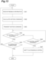
- This procedure is a control procedure executed by the server device 100 in the server control mode described above.
- the server device 100 executes steps S41, S42, S43, S44.
- the information reception unit 121 acquires feedback information indicating the current position and posture of the body 30.
- the command calculation unit 122 calculates a target position and posture for each control cycle based on a predetermined operation program, and calculates a motion command so that the current position and posture of the body 30 follow the target position and posture.
- the command transmission unit 123 transmits the motion command to the local controller 300.
- the command calculation unit 122 checks whether the control cycle has elapsed from immediately before the start of the step S41.
- step S44 the server device 100 executes a step S46.
- the command calculation unit 122 checks whether the control mode is changed from the server control mode to the autonomous control mode. If it is determined in the step S46 that the control mode is not changed, the server device 100 returns the process to the step S44. Thereafter, the server device 100 waits for the control cycle to elapse or the control mode to be changed.
- step S45 the command calculation unit 122 checks whether all operations based on the operation program are completed. If it is determined in the step S45 that not all operations are completed, the server device 100 returns the process to the step S41. If it is determined in the step S45 that all the operations are completed, the server device 100 completes the control by the server control mode.
- step S46 If it is determined in the step S46 that the control mode is changed, the server device 100 executes a step S47.
- step S47 each of the information reception unit 121, the command calculation unit 122, and the command transmission unit 123 starts processing for the autonomous control mode. Thus, the control by the server control mode is completed.
- This procedure is a control procedure executed by the server device 100 in the above-described autonomous control mode.
- the server device 100 executes steps S51, S52.
- the command transmission unit 123 transmits an operation command based on autonomous control to the local controller 300.
- the information reception unit 121 checks whether a completion notification of all operations in the autonomous control is received from the local controller 300.
- the server device 100 executes a step S53.
- the command calculation unit 122 checks whether the control mode is changed from the autonomous control mode to the server control mode. If it is determined in the step S53 that the control mode is not changed, the server device 100 returns the process to the step S52. Thereafter, the server device 100 waits for completion notifications of all operations to be received or the control mode to be changed.
- the server device 100 completes the control in the autonomous control mode. If it is determined in the step S53 that the control mode is changed, the server device 100 executes a step S54. In the step S54, each of the information reception unit 121, the command calculation unit 122, and the command transmission unit 123 starts processing for the server control mode. Thus, the control in the autonomous control mode is completed.
Landscapes
- Engineering & Computer Science (AREA)
- Aviation & Aerospace Engineering (AREA)
- Radar, Positioning & Navigation (AREA)
- Remote Sensing (AREA)
- Physics & Mathematics (AREA)
- General Physics & Mathematics (AREA)
- Automation & Control Theory (AREA)
- Computer Networks & Wireless Communication (AREA)
- Signal Processing (AREA)
- Mobile Radio Communication Systems (AREA)
Abstract
Description
- The present disclosure relates to a communication system and a communication terminal.
-
Patent Document 1 discloses a system including a robot, a machining device, a robot controller that controls the robot, a machining device controller that controls the machining device, and a programmable logic controller that generates commands for the robot controller and the machining device controller. - [Patent Document 1]
Japanese Unexamined Patent Publication No. 2019-209454 - The present disclosure provides a communication system effective for improving reliability of inter-device communication by mobile wireless communication.
- A communication system according to an aspect of the present disclosure includes: a host system including a client device and a server device configured to perform inter-device communication with the client device; and a communication terminal connected to the client device and configured to perform mobile wireless communication for inter-device communication with a base station connected to the server device, wherein the communication terminal is configured to notify the host system of information of the base station.
- A communication terminal according to another aspect of the present disclosure is a communication terminal that is connected to a client device of a host system including the client device and a server device that are configured to perform inter-device communication with each other, the communication terminal being configured to perform mobile wireless communication for the inter-device communication with a base station connected to the server device, the communication terminal including: a base station information acquisition unit configured to acquire information of the base station; and a notification unit configured to notify a system of information of the base station.
- According to the present disclosure, it is possible to provide a communication system effective for improving reliability of inter-device communication by mobile wireless communication.
-
-
FIG. 1 is a schematic diagram illustrating an example configuration of a machine system. -
FIG. 2 is a schematic diagram illustrating an example configuration of a robot. -
FIG. 3 is a schematic diagram illustrating an example system in which a server device changes a control mode based on information of a base station notified from a communication terminal. -
FIG. 4 is a block diagram illustrating an example functional configuration of a communication terminal and a local controller. -
FIG. 5 is a block diagram illustrating an example functional configuration of the base station and the server device. -
FIG. 6 is a block diagram illustrating an example functional configuration of a controller in the server device. -
FIG. 7 is a block diagram illustrating an example hardware configuration of the server device and the base station. -
FIG. 8 is a block diagram illustrating an example hardware configuration of the communication terminal and the local controller. -
FIG. 9 is a flowchart illustrating an example connection procedure between the communication terminal and the base station. -
FIG. 10 is a flowchart illustrating an example control procedure of the communication terminal by a host system. -
FIG. 11 is a flowchart illustrating an example procedure for changing the control mode based on information of the base station. -
FIG. 12 is a flowchart illustrating an example procedure for changing the control mode based on a sign of handover. -
FIG. 13 is a flowchart illustrating an example control procedure in a server control mode. -
FIG. 14 is a flowchart illustrating an example control procedure in an autonomous control mode. - Hereinafter, an embodiment will be described in detail with reference to the drawings. In the description, the same elements or elements having the same functions are denoted by the same symbols, and redundant description will be omitted.
-
FIG. 1 is a schematic view illustrating a machine system. Amachine system 1 illustrated inFIG. 1 includes aserver device 100 and a plurality ofmachines 20. Each of the plurality ofmachines 20 performs motions. Although threemachines 20 are illustrated inFIG. 1 , the number of themachines 20 is not limited to this. - Each of the plurality of
machines 20 includes abody 30 and alocal controller 300. Thebody 30 is a machine that is controlled by thelocal controller 300 and performs multiple types of motion. The type of thebody 30 is not particularly limited. - As an example, two types of
bodies FIG. 1 . Thebody 30A is a mobile robot, and performs motions for conveying, processing, assembling, and the like on a workpiece. Specific examples of the motions include a motion for conveying a component and attaching the component to a workpiece, a motion for conveying a tool such as a screw tightening tool or a welding torch and processing the workpiece, and a motion for conveying the workpiece itself. - The
body 30 includes an automated guidedvehicle 31 and arobot 40. The automated guidedvehicle 31 supports and moves therobot 40. Therobot 40 is, for example, a vertical articulated industrial robot. As illustrated inFIG. 2 , therobot 40 includes abase 41, apivoting portion 42, afirst arm 43, asecond arm 44, awrist portion 45, and atip portion 46. Thebase 41 is placed on top of the automated guidedvehicle 31. The pivotingportion 42 is mounted on thebase 41 so as to be rotatable about avertical axis 51. For example, therobot 40 includes a joint 61 that attaches thepivoting portion 42 to thebase 41 so as to be rotatable about theaxis 51. Thefirst arm 43 is connected to thepivoting portion 42 so as to be rotatable about anaxis 52 intersecting (for example, orthogonal to) theaxis 51. For example, therobot 40 includes a joint 62 that connects thefirst arm 43 to thepivoting portion 42 so as to be rotatable about theaxis 52. Intersecting includes being skewed, such as so-called grade separation. The same applies to the following. Thefirst arm 43 extends from thepivoting portion 42 along a direction that intersects (for example, is orthogonal to) theaxis 52. - The
second arm 44 is connected to the end of thefirst arm 43 so as to be rotatable about anaxis 53 parallel to theaxis 52. For example, therobot 40 includes a joint 63 that connects thesecond arm 44 to thefirst arm 43 so as to be rotatable about theaxis 53. Thesecond arm 44 includes anarm base 47 that extends from the end of thefirst arm 43 along one direction that intersects (for example, is orthogonal to) theaxis 53, and anarm end 48 that further extends from the end of thearm base 47 along the same one direction. Thearm end 48 is rotatable about anaxis 54 relative to thearm base 47. Theaxis 54 intersects (for example, is orthogonal to) theaxis 53. For example, therobot 40 includes a joint 64 that connects thearm end 48 to thearm base 47 so as to be rotatable about theaxis 54. - The
wrist portion 45 is connected to thearm end 48 so as to be rotatable about anaxis 55 that intersects (for example, is orthogonal to) theaxis 54. For example, therobot 40 includes a joint 65 that connects thewrist portion 45 to thearm end 48 so as to be rotatable about theaxis 55. Thewrist portion 45 extends from the end of thearm end 48 along one direction that intersects (for example, is orthogonal to) theaxis 55. Thetip portion 46 is connected to the end of thewrist portion 45 so as to be rotatable about anaxis 56 that intersects (for example, is orthogonal to) theaxis 55. For example, therobot 40 includes a joint 66 that connects thetip portion 46 to thewrist portion 45 so as to be rotatable about theaxis 56. An end effector is provided on thetip portion 46. Specific examples of the end effector include a hand that grips a workpiece, and a work tool that performs processing, assembly, or the like on a workpiece. - Actuators 71, 72, 73, 74, 75, 76 drive the joints 61, 62, 63, 64, 65, 66. Each of the actuators 71, 72, 73, 74, 75, 76 includes, for example, an electric motor and a transmission unit (for example, a reduction gear) that transmits the power of the electric motor to the joints 61, 62, 63, 64, 65, 66. For example, the actuator 71 drives the joint 61 so as to rotate the pivoting
portion 42 about theaxis 51. The actuator 72 drives the joint 62 so as to rotate thefirst arm 43 about theaxis 52. The actuator 73 drives the joint 63 so as to rotate thesecond arm 44 about theaxis 53. The actuator 74 drives the joint 64 so as to rotate thearm end 48 about theaxis 54. The actuator 75 drives the joint 65 so as to rotate thewrist portion 45 about theaxis 55. The actuator 76 drives the joint 66 so as to rotate thetip portion 46 about theaxis 56. - The
body 30 is not necessarily limited to the above-described mobile robot, and may be a robot fixed at a fixed position. Thebody 30 may be an automated guided vehicle that performs a motion for conveying a conveyance object such as a workpiece. - The
body 30B is an automated guided vehicle that conveys a conveyance object such as a workpiece. Thebody 30B includes an automated guidedvehicle 33 and a loading table 34. The automated guidedvehicle 33 supports and moves the loading table 34. The loading table 34 supports the conveyance object. - The
server device 100 performs inter-device communication with thelocal controller 300 of the plurality ofmachines 20, and causes thebodies 30 of the plurality ofmachines 20 to perform a series of motions for production of a workpiece or the like. For the inter-device communication, themachine system 1 includes acommunication system 10. - The
communication system 10 includes ahost system 11 and acommunication terminal 400. Thehost system 11 includes themachine 20 that is an example of a client device, and theserver device 100 that performs inter-device communication with the client device. - The inter-device communication is communication performed between devices to control motion, for example, as described above. Such inter-device communication may include transmission and reception of control commands, transmission and reception of feedback information during control, transmission and reception of operation completion notifications in response to a control command, and the like.
- The
communication terminal 400 is connected to thelocal controller 300 and performs mobile wireless communication for inter-device communication with abase station 200 connected to theserver device 100. Examples of the mobile wireless communication include, but are not necessarily limited to, communication using a fifth-generation mobile communication system (5G communication). For example, thecommunication terminal 400 is fixed to thebody 30 and moves together with thebody 30. Accordingly, thecommunication terminal 400 can be moved by thelocal controller 300. - As illustrated in
FIG. 3 , a plurality ofbase stations 200 may be connected to theserver device 100. In a system in which a plurality ofbase stations 200 may be connected to theserver device 100, a connection state between thecommunication terminal 400 and the plurality ofbase stations 200 may have an influence on reliability of inter-device communication. For example, there is a possibility that mobile wireless communication satisfying a requirement for the inter-device communication cannot be performed depending on specifications of thebase station 200 to which thecommunication terminal 400 is connected because the specifications of the plurality ofbase stations 200 are different from each other. For example, in thebase station 200 whose communication speed is low, there is a possibility that inter-device communication cannot be performed at a sufficiently high speed. Even in abase station 200 whose communication speed according to the specifications is sufficient, there is a possibility that inter-device communication cannot be performed at a sufficient speed because thebase station 200 is shared by many terminals. In thebase station 200 whose radio field strength is weak, there is a possibility that the reliability of communication required for inter-device communication cannot be secured. In addition, there is a possibility that it is difficult to continue inter-device communication at a necessary communication cycle due to handover occurring between the plurality ofbase stations 200. - Thus, the
communication terminal 400 is configured to notify thehost system 11 of information of thebase station 200. Accordingly, in thehost system 11, it is possible to cope with the above-described influence based on the information of thebase station 200. Examples of coping with the above-described influence include changing the control mode of thebody 30 by theserver device 100, as illustrated inFIG. 3 . - As an example of notifying the
host system 11 of the information of thebase station 200, thecommunication terminal 400 may notify thelocal controller 300 of the information of thebase station 200, may notify theserver device 100 of the information of thebase station 200, or may notify both thelocal controller 300 and theserver device 100 of the information of thebase station 200. Notifying theserver device 100 of the information of thebase station 200 includes notifying thelocal controller 300 of the information of thebase station 200 and causing thelocal controller 300 to transmit the information of thebase station 200 to theserver device 100. - The information of the
base station 200 may include both information of thebase station 200 that is connected and information of thebase station 200 that is not connected. The information of thebase station 200 includes, for example, identification information of thebase station 200. The identification information of thebase station 200 may be, for example, information that can identify theindividual base station 200 or information that can identify attributes of thebase station 200. Examples of the information that can identify the attributes of thebase station 200 include information indicating the type of thebase station 200 and information indicating the specifications of thebase station 200. - The information of the
base station 200 may include information of a communication state between thelocal controller 300 and thecommunication terminal 400. Examples of the information of the communication state include information on radio waves received from the base station 200 (for example, information on the strength of radio waves), information indicating a sign of handover from a connectedbase station 200 to anotherbase station 200, and the like. -
FIG. 4 is a block diagram illustrating a functional configuration of thecommunication terminal 400 and thelocal controller 300. As illustrated inFIG. 4 , thecommunication terminal 400 includes atransceiver unit 411, atransmission buffer 412, areception buffer 413, a base stationinformation acquisition unit 414, and anotification unit 415 as functional constituent elements (hereinafter referred to as "functional blocks"). Thetransceiver unit 411 performs mobile wireless communication with thebase station 200. Thetransmission buffer 412 temporarily stores information that thetransceiver unit 411 transmits to thebase station 200 through mobile wireless communication. Thereception buffer 413 temporarily stores information received by thetransceiver unit 411 from thebase station 200 through mobile wireless communication. The base stationinformation acquisition unit 414 acquires the information of thebase station 200 from the information that thetransceiver unit 411 received from thebase station 200. Thenotification unit 415 notifies thelocal controller 300 of the information of thebase station 200. - As illustrated in
FIG. 4 , thelocal controller 300 includes acommunication control unit 311 and amotion control unit 312 as functional blocks. Thecommunication control unit 311 performs inter-device communication with theserver device 100. For example, thecommunication control unit 311 stores, in thetransmission buffer 412, information to be transmitted from thecommunication terminal 400 to thebase station 200, and reads, from thereception buffer 413, information that thecommunication terminal 400 receives from thebase station 200. - The
motion control unit 312 controls thebody 30 based on the control command received by thecommunication control unit 311 from theserver device 100. Themotion control unit 312 may be configured to autonomously perform at least a part of the control of thebody 30 without being based on the control command from theserver device 100. In this case, thelocal controller 300 controls thebody 30 based on, for example, an operation program stored therein. The operation program includes a plurality of operation commands arranged in time series. Each of the plurality of operation commands includes an operation target position and an operation target speed of thebody 30. Examples of the operation target position of thebody 30 include an operation target position of thetip portion 46. The operation target position of thetip portion 46 includes an operation target posture of thetip portion 46. - The
communication control unit 311 receives notification of the information of thebase station 200 from thenotification unit 415. When receiving the notification of the information of thebase station 200, thecommunication control unit 311 may store the information of thebase station 200 in thetransmission buffer 412 and cause thecommunication terminal 400 to transmit the information to thebase station 200. Thus, the information of thebase station 200 is also notified to theserver device 100. - Note that the
communication terminal 400 may be configured to notify theserver device 100 of the information of thebase station 200 without going through thelocal controller 300. For example, thenotification unit 415 may store the information of thebase station 200 in thetransmission buffer 412 and cause thecommunication terminal 400 to transmit the information to thebase station 200. - If the information of the
base station 200 includes identification information of thebase station 200, thecommunication control unit 311 may control thecommunication terminal 400 to be connected to thebase station 200 that is predetermined (default base station). For example, thecommunication control unit 311 designates the default base station and requests thetransceiver unit 411 to limit the connection destination so as to be preferentially connected to the default base station. Thetransceiver unit 411 controls a transmission/reception direction of a radio signal by beam forming or the like so as to be easily connected to the default base station. - The
communication control unit 311 may request thetransceiver unit 411 to connect to the base station 200 (including reconnection) after moving thebody 30 using themotion control unit 312 so that thecommunication terminal 400 approaches the default base station. Thecommunication control unit 311 may execute both moving thebody 30 using themotion control unit 312 so that thecommunication terminal 400 approaches the default base station, and controlling thetransceiver unit 411 to be preferentially connected to the default base station. -
FIG. 5 is a block diagram illustrating a functional configuration of thebase station 200 and theserver device 100. As illustrated inFIG. 5 , thebase station 200 includes atransceiver unit 211, atransmission buffer 212, areception buffer 213, and a base stationinformation addition unit 214 as functional blocks. Thetransceiver unit 211 performs mobile wireless communication with thecommunication terminal 400. Thetransmission buffer 212 temporarily stores information that thetransceiver unit 211 transmits to thecommunication terminal 400 through mobile wireless communication. Thereception buffer 213 temporarily stores information received by thetransceiver unit 211 from thecommunication terminal 400 through mobile wireless communication. The base stationinformation addition unit 214 adds the above-described information of thebase station 200 to the information that thetransceiver unit 211 transmits to thecommunication terminal 400. - The
server device 100 includes acommunication control unit 111 and a plurality ofcontrollers 120 as functional blocks. Thecommunication control unit 111 performs inter-device communication with thelocal controller 300. For example, thecommunication control unit 111 stores, in thetransmission buffer 212, information to be transmitted from thebase station 200 to thecommunication terminal 400, and reads, from thereception buffer 213, information that thebase station 200 receives from thecommunication terminal 400. - As described above, when the information of the
base station 200 is transmitted from thecommunication terminal 400 to thebase station 200, thecommunication control unit 111 receives the information of thebase station 200. As a result, thecommunication control unit 111 is notified of the information of thebase station 200. Instead of thecommunication control unit 311, thecommunication control unit 111 may control thecommunication terminal 400 to be connected to the default base station. For example, thecommunication control unit 111 stores a request for restriction of a connection destination by beam forming or the like in thetransmission buffer 212. - Instead of the
communication control unit 311, thecommunication control unit 111 may request thetransceiver unit 411 to connect to the base station 200 (including reconnection) after moving thebody 30 using themotion control unit 312 so that thecommunication terminal 400 approaches the default base station. For example, thecommunication control unit 111 stores, in thetransmission buffer 212, a command to move thebody 30 using themotion control unit 312 so that thecommunication terminal 400 approaches the default base station, and stores, in thetransmission buffer 212, a request to connect to thebase station 200 for thetransceiver unit 411 after reading a completion notification of the movement of thebody 30 from thereception buffer 213. - Each of the plurality of
controllers 120 controls each of the plurality ofmachines 20 through inter-device communication performed by thecommunication control unit 111. For example, as illustrated inFIG. 6 , each of the plurality ofcontrollers 120 includes aninformation reception unit 121, acommand calculation unit 122, acommand transmission unit 123, amode change unit 124, and asign detection unit 125 as functional blocks. - The
information reception unit 121 receives feedback information indicating a state of a correspondingmachine 20 through inter-device communication. Examples of the feedback information include information indicating the current position and posture of thebody 30. Examples of the current position and posture of thebody 30 include the current position and posture of the automated guidedvehicle 31 in thebody 30A and the current position and posture of therobot 40 in the automated guidedvehicle 31. The information indicating the current position and posture of therobot 40 may be the current angles of the joints 61, 62, 63, 64, 65, 66. The feedback information may be status information indicating whether the operation based on the command from theserver device 100 is completed. - The
command calculation unit 122 calculates a motion command based on the feedback information. The motion command is a command to cause thelocal controller 300 to cause thebody 30 to perform a motion. Examples of the motion command include a speed command or a force (torque) command for causing the current position and posture of thebody 30 to follow the target position and posture. The motion command may be a start command of a predetermined series of operations. - The
command transmission unit 123 transmits the motion command to thelocal controller 300 of the correspondingmachine 20 through inter-device communication. - The
mode change unit 124 changes the control mode of themachine 20 by thecontroller 120 based on the information of thebase station 200. For example, themode change unit 124 changes the control mode of themachine 20 by thecontroller 120 from one of a plurality of predetermined modes to another. - The
mode change unit 124 may change the control mode to reduce the influence of whichcontroller 120 thecommunication terminal 400 is connected to. For example, the plurality of control modes may include a server control mode and an autonomous control mode. The server control mode is a mode in which thecontroller 120 controls the motion of thebody 30 through inter-device communication. The autonomous control mode is a mode in which thelocal controller 300 autonomously controls the motion of thebody 30. In this case, for example, thecontroller 120 transmits a motion start command to thelocal controller 300 and receives a motion completion notification from thelocal controller 300. In the autonomous control mode, the frequency of inter-device communication is lower than in the server control mode. Accordingly, in the autonomous control mode, the influence of which thecontroller 120 thecommunication terminal 400 is connected to is smaller than that in the server control mode. - Examples of the server control mode include a mode in which the motion of the
body 30 is feedback-controlled by theserver device 100. In this control mode, thecontroller 120 repeatedly executes reception of the feedback information by theinformation reception unit 121, generation of the motion command by thecommand calculation unit 122, and transmission of the motion command by thecommand transmission unit 123 at a predetermined control cycle. - For example, the
information reception unit 121 receives feedback information indicating the current position and posture of thebody 30. Thecommand calculation unit 122 calculates a target position and posture for each control cycle based on a predetermined operation program, and calculates a motion command so that the current position and posture of thebody 30 match the target position and posture. Making the current position and posture of thebody 30 follow the target position and posture means changing the current position and posture in accordance with the change of the target position and posture so that the deviation between the target position and posture and the current position and posture remains within a predetermined range. For example, thecommand calculation unit 122 calculates the motion command by performing a proportional operation, a proportional-integral operation, a proportional-integral-differential operation, or the like on the deviation between the target position and posture and the current position and posture. - When such cyclic control is performed through inter-device communication, there is a possibility that the reception timing of the feedback information and the reception timing of the motion command vary due to a communication delay. In order to suppress the variation, the
command transmission unit 123 may add first cycle information designating a control cycle in which the motion command is to be read to the motion command and transmit the motion command to thelocal controller 300. In this case, thecommunication control unit 311 stores the received motion command until the control cycle designated by the first cycle information, and themotion control unit 312 reads the motion command in the control cycle and controls thebody 30 based on the read motion command. - Similarly, the
communication control unit 311 in thelocal controller 300 may add second cycle information designating the control cycle in which the feedback information is to be read to the feedback information and transmit the feedback information to theserver device 100. In this case, thecommunication control unit 111 stores the feedback information until the control cycle designated by the second cycle information, theinformation reception unit 121 reads the feedback information in the control cycle, and thecommand calculation unit 122 generates the motion command based on the read feedback information. Accordingly, the influence of the variation in the reception timing of the feedback information and the motion command on the motion of thebody 30 is suppressed. - In order to perform such a cyclic server control mode with high reliability, a predetermined condition may be required for the capability of the
base station 200. In such a case, thebase station 200 satisfying a predetermined condition is set as the above-described default base station. Themode change unit 124 sets the control mode of themachine 20 to the server control mode if it determines that the base station 200 (thebase station 200 to which thecommunication terminal 400 is connected) is the default base station based on the information of thebase station 200, and sets the control mode of themachine 20 to the autonomous control mode if it determines that thebase station 200 is not the default base station. - For example, if it is determined that the state is switched from a state in which the
base station 200 is the default base station to a state in which thebase station 200 is not the default base station (handover from the default base station to another base station has occurred), themode change unit 124 changes the server control mode to the autonomous control mode. In addition, themode change unit 124 changes the autonomous control mode to the server control mode if it is determined that the state is switched from a state in which thebase station 200 is not the default base station to a state in which thebase station 200 is the default base station (handover from another base station to the default base station has occurred). - The plurality of control modes may include a stop mode for keeping the
body 30 in a stopped state. Themode change unit 124 may set the control mode of themachine 20 to the server control mode if it is determined that thebase station 200 is the default base station based on the information of thebase station 200, and may set the control mode of themachine 20 to the stop mode if it is determined that thebase station 200 is not the default base station. - For example, the
mode change unit 124 changes the control mode of themachine 20 from the server control mode to the stop mode if it is determined that the state is changed from a state in which thebase station 200 is the default base station to a state in which thebase station 200 is not the default base station (handover from the default base station to another base station occurs). In addition, themode change unit 124 changes the control mode of themachine 20 from the stop mode to the server control mode if it is determined that the state is changed from a state in which thebase station 200 is not the default base station to a state in which thebase station 200 is the default base station (handover from another base station to the default base station occurs). - The
mode change unit 124 may change the control mode so that thecommunication terminal 400 is more easily connected to the default base station. The plurality of control modes may include a first control mode in which the movement range of thebody 30 reaches a position farther than a predetermined reference distance from the default base station, and a second control mode in which the movement range of thebody 30 falls within the reference distance from the default base station. The second control mode may be a mode in which thebody 30 is operated at a fixed position. For example, the second control mode may be a mode in which therobot 40 is operated with the automated guidedvehicle 31 located at a fixed position. - In the second control mode, the
body 30 operates at a position closer to the default base station than in the first control mode. Accordingly, in the second control mode, thecommunication terminal 400 is more easily connected to the default base station as compared with the first control mode. For example, if it is determined that thebase station 200 is not the default base station based on the information of thebase station 200 while themode change unit 124 is controlling themachine 20 in the first control mode, themode change unit 124 changes the control mode of themachine 20 from the first control mode to the second control mode. - The
sign detection unit 125 detects the sign of handover of thebase station 200 based on the information of thebase station 200. For example, thesign detection unit 125 detects the sign of handover based on information of radio waves received by thecommunication terminal 400 from thebase station 200. For example, thesign detection unit 125 detects the sign of handover when the strength of radio waves received by thecommunication terminal 400 from thebase station 200 falls below a predetermined reference strength. - The information on the
base station 200 may further include information on whether thecommunication terminal 400 receives an instruction to connect to abase station 200 other than thebase station 200 being connected (hereinafter referred to as "handover instruction"). In this case, thesign detection unit 125 may detect the sign of handover when thecommunication terminal 400 is receiving the handover instruction. - The
sign detection unit 125 may detect the sign of handover based on both whether thecommunication terminal 400 receives the handover instruction and the information of the radio waves received by thecommunication terminal 400 from thebase station 200. For example, thesign detection unit 125 may detect a sign of handover when thecommunication terminal 400 receives a handover instruction and the strength of radio waves received by thecommunication terminal 400 from thebase station 200 falls below a reference strength. - The
communication terminal 400 may be configured to detect the sign of handover, and may be configured to notify thehost system 11 of a detection result of the sign of handover by including the detection result in the information of thebase station 200. In this case, thesign detection unit 125 detects the sign of handover based on the detection result of the sign of handover by thecommunication terminal 400. - The
mode change unit 124 may change the control mode based on the sign of handover if thesign detection unit 125 detects the sign of handover. - For example, the
mode change unit 124 may change the control mode based on the sign of handover so as to reduce the influence of the handover. For example, themode change unit 124 may change the server control mode to the autonomous control mode or the stop mode if thesign detection unit 125 detects a sign of handover during execution of the server control mode. After switching the server control mode to the autonomous control mode or the stop mode, themode change unit 124 may change the autonomous control mode to the server control mode if thesign detection unit 125 does not detect the sign of handover due to the completion of the handover or the like. - The
mode change unit 124 may change the control mode based on the sign of handover so as to reduce the sign of handover. The plurality of control modes may include a first control mode in which the movement range of thebody 30 reaches a position farther than a predetermined reference distance from the connected base station, and a second control mode in which the movement range of thebody 30 falls within the reference distance from the connected base station. The second control mode may be a mode in which thebody 30 is operated at a fixed position. - In the second control mode, the
body 30 operates at a position closer to the connected base station as compared with the first control mode. Accordingly, in the second control mode, the sign of handover is reduced compared to the first control mode. For example, themode change unit 124 changes the control mode of themachine 20 from the first control mode to the second control mode if a sign of handover is detected by thesign detection unit 125 while themachine 20 is controlled in the first control mode. - The
communication control unit 111 may control thecommunication terminal 400 to decrease the sign of handover if the sign of handover is detected by thesign detection unit 125. For example, thecommunication control unit 111 designates thebase station 200 being connected so as to reduce the sign of handover, and stores a request for restriction of a connection destination in thetransmission buffer 212. Thetransceiver unit 411 controls the transmission/reception direction of a radio signal by beam forming or the like so as to reduce the sign of handover. - In the above description, a configuration in which the
mode change unit 124 and thesign detection unit 125 are provided in theserver device 100 has been described, but they may be provided in thelocal controller 300. -
FIG. 7 is a block diagram illustrating a hardware configuration of theserver device 100 and thebase station 200. As illustrated inFIG. 7 , theserver device 100 includescircuitry 190. Thecircuitry 190 includes aprocessor 191, amemory 192,storage 193, and a user interface 195. Thestorage 193 is a nonvolatile storage medium. Specific examples of thestorage 193 include a hard disk and a flash memory. Thestorage 193 may be a portable storage media such as an optical disc. Thestorage 193 stores a program for configuring the above-described functional blocks in theserver device 100. - The
memory 192 is a temporary memory such as a random-access memory, and temporarily stores the program that is loaded from thestorage 193. Theprocessor 191 is configured by one or more arithmetic elements, and causes theserver device 100 to configure each of the functional blocks by executing the program loaded in thememory 192. Acommunication port 194 communicates with thebase station 200 in response to a request from theprocessor 191. - The
base station 200 includescircuitry 290. Thecircuitry 290 includes aprocessor 291, amemory 292,storage 293, acommunication port 294, and anantenna 295. Thestorage 293 is a nonvolatile storage medium. Specific examples of thestorage 293 include a hard disk and a flash memory. Thestorage 293 may be a portable storage media such as an optical disc. Thestorage 293 stores a program for configuring the above-described functional blocks in thebase station 200. - The
memory 292 is a temporary memory such as a random-access memory, and temporarily stores the program that is loaded from thestorage 293. Theprocessor 291 is configured by one or more arithmetic elements, and causes thebase station 200 to configure each of the functional blocks by executing the program loaded in thememory 292. Thecommunication port 294 communicates with thecommunication port 194 in response to a request from theprocessor 291. Theantenna 295 transmits and receives a signal for mobile wireless communication in response to a request from theprocessor 291. -
FIG. 8 is a block diagram illustrating a hardware configuration of thelocal controller 300 and thecommunication terminal 400. As illustrated inFIG. 8 , thelocal controller 300 includescircuitry 390. Thecircuitry 390 includes aprocessor 391, amemory 392,storage 393, acommunication port 394, and drivecircuitry 395. - The
storage 393 is a nonvolatile storage medium. Specific examples of thestorage 393 include a hard disk and a flash memory. Thestorage 393 may be a portable storage media such as an optical disc. Thestorage 393 stores a program for configuring the above-described functional blocks in thelocal controller 300. - The
memory 392 is a temporary memory such as a random-access memory, and temporarily stores the program that is loaded from thestorage 393. Theprocessor 391 is configured by one or more arithmetic elements, and causes thelocal controller 300 to configure each of the functional blocks by executing the program loaded in thememory 392. Thecommunication port 394 communicates with thecommunication terminal 400 in response to a request from theprocessor 391. Thedrive circuitry 395 outputs driving power to thebody 30 in response to a request from theprocessor 391, and acquires feedback information from thebody 30. - The
communication terminal 400 includescircuitry 490. Thecircuitry 490 includes aprocessor 491, amemory 492,storage 493, acommunication port 494, and anantenna 495. Thestorage 493 is a nonvolatile storage medium. Specific examples of thestorage 493 include a hard disk and a flash memory. Thestorage 493 may be a portable storage media such as an optical disc. Thestorage 493 stores a program for configuring the above-described functional blocks in thecommunication terminal 400. - The
memory 492 is a temporary memory such as a random-access memory, and temporarily stores the program that is loaded from thestorage 493. Theprocessor 491 is configured by one or more arithmetic elements, and causes thecommunication terminal 400 to configure each of the functional blocks by executing the program loaded in thememory 492. Thecommunication port 494 communicates with thecommunication port 394 in response to a request from theprocessor 491. Theantenna 495 transmits and receives a signal for mobile wireless communication in response to a request from theprocessor 491. - Hereinafter, as an example of the control method, a control procedure including a communication procedure in the
communication system 10 will be described. This control procedure includes a connection procedure between thecommunication terminal 400 and thebase station 200, a control procedure of thecommunication terminal 400 by thehost system 11, a change procedure of the control mode based on information of thebase station 200, a change procedure of the control mode based on the sign of handover, a control procedure by server control mode, and a control procedure by autonomous control mode. Each procedure will be described below. - As illustrated in
FIG. 9 , thecommunication terminal 400 first executes steps S01, S02. In the step S01, the base stationinformation acquisition unit 414 acquires information of thebase station 200. In the step S02, thenotification unit 415 notifies thelocal controller 300 of the information of thebase station 200. - The
communication terminal 400 then executes a step S03. In the step S03, thetransceiver unit 411 checks whether a request for connection to thebase station 200 is received from thelocal controller 300. If it is determined in the step S03 that the request for connection is not received, thecommunication terminal 400 executes a step S04. In the step S04, thetransceiver unit 411 checks whether a request for restricting connection destination restriction (for example, the above-described request for beam forming or the like) is received from thelocal controller 300. If it is determined in the step S04 that the request for restricting the connection destination is not received, thecommunication terminal 400 returns the process to the step S01. - If it is determined in the step S04 that the request for restricting the connection destination is received, the
communication terminal 400 executes a step S05. In the step S05, thetransceiver unit 411 controls the transmission/reception direction of a wireless signal so that thetransceiver unit 411 can be easily connected to thebase station 200 designated in the request for restriction of a connection destination. - If it is determined in the step S03 that a connection request is received, the
communication terminal 400 executes a step S06. In the step S06, thetransceiver unit 411 establishes a connection with thebase station 200. - The procedure described below can be executed by either the
server device 100 or thelocal controller 300 in a state where a connection is established between thebase station 200 and thecommunication terminal 400. It is assumed that the connection between thebase station 200 and thecommunication terminal 400 is not established, and the following procedure is executed by thelocal controller 300. - As illustrated in
FIG. 10 , thelocal controller 300 first executessteps S 11, S12. In thestep S 11, thecommunication control unit 311 waits for the notification of information of thebase station 200 from thenotification unit 415. For example, thecommunication control unit 311 waits for notification from thenotification unit 415 of information of thebase station 200 to which thecommunication terminal 400 can connect. Hereinafter, thebase station 200 to which thecommunication terminal 400 can be connected is referred to as a "candidate base station 200". - In the step S12, the
communication control unit 311 checks whether thecandidate base station 200 is the default base station based on the information of thecandidate base station 200. If it is determined in the step S12 that thecandidate base station 200 is not the default base station, thecommunication control unit 311 executes steps S13, S14, S15. - In the step S13, the
communication control unit 311 designates the default base station and requests thetransceiver unit 411 to restrict the connection destination. In response to this, thetransceiver unit 411 controls the transmission/reception direction of the radio signal so as to facilitate connection to the default base station (the step S05 described above). In thestep S 14, thecommunication control unit 311 waits for the information of thecandidate base station 200 to be notified again from thenotification unit 415. In the step S15, thecommunication control unit 311 checks whether thecandidate base station 200 is the default base station based on the information of thecandidate base station 200. - If it is determined in the step S15 that the
candidate base station 200 is not the default base station, thelocal controller 300 executes a step S16. In the step S16, thecommunication control unit 311 moves thebody 30 with themotion control unit 312 so that thecommunication terminal 400 approaches the default base station. Thelocal controller 300 then returns the process to the step S13. - If it is determined in the step S12 that the
candidate base station 200 is the default base station or if it is determined in the step S15 that thecandidate base station 200 is the default base station, thelocal controller 300 executes astep S 17. In the step S17, thecommunication control unit 311 requests thetransceiver unit 411 to connect with thebase station 200. In response, thetransceiver unit 411 establishes a connection with the base station 200 (the step S06 described above). Thus, the control procedure of thecommunication terminal 400 is completed. - This procedure is executed after the connection between the
base station 200 and thecommunication terminal 400 has been established. As illustrated inFIG. 11 , theserver device 100 first executes steps S21, S22. In the step S21, thecommunication control unit 111 waits for the notification of the information of thebase station 200 from thenotification unit 415. In the step S22, thecommunication control unit 111 checks whether the connection between thecommunication terminal 400 and thebase station 200 is maintained based on the information of thebase station 200 notified from thenotification unit 415. If it is determined in the step S22 that the connection between thecommunication terminal 400 and thebase station 200 is maintained, theserver device 100 executes a step S23. In the step S23, based on the information of thebase station 200 acquired by thecommunication control unit 111, themode change unit 124 checks whether thebase station 200 is the default base station. - If it is determined in the step S23 that the
base station 200 is the default base station, theserver device 100 executes a step S24. In the step S24, themode change unit 124 sets the control mode to the server control mode described above. If it is determined in the step S23 that thebase station 200 is not the default base station, theserver device 100 executes a step S25. In the step S25, themode change unit 124 sets the control mode to the autonomous control mode described above. After the steps S24, S25, theserver device 100 returns the process to the step S21. Until it is determined that the connection between thecommunication terminal 400 and thebase station 200 is not maintained in the step S22, theserver device 100 repeatedly executes the above processing. If it is determined in the step S22 that the connection between thecommunication terminal 400 and thebase station 200 is not maintained, theserver device 100 ends the process. Thereafter, for example, the procedure illustrated inFIG. 10 is executed again. - This procedure is executed after the connection between the
base station 200 and thecommunication terminal 400 is established and the control of themachine 20 by theserver device 100 is started. As illustrated inFIG. 12 , theserver device 100 first executes a step S31. In the step S31, thecommunication control unit 111 waits for thecommunication control unit 111 to be notified of the information of thebase station 200 from thenotification unit 415. - The
server device 100 then executes a step S32. In the step S32, thesign detection unit 125 checks whether there is a sign of handover of thebase station 200 based on the information of thebase station 200. If it is determined in the step S32 that there is no sign of handover, theserver device 100 returns the process to the step S31. - If it is determined in the step S32 that there is a sign of handover (if a sign of handover is detected), the
server device 100 executes a step S33. In the step S33, thecommunication control unit 111 designates thebase station 200 being connected so as to reduce the sign of handover, and stores a request for restriction of a connection destination in thetransmission buffer 212. Thetransceiver unit 411 controls the transmission/reception direction of a radio signal by beam forming or the like so as to reduce the sign of handover. - The
server device 100 then executes a step S34. In the step S34, thecommunication control unit 111 waits for thecommunication control unit 111 to be notified of the information of thebase station 200 from thenotification unit 415. In a step S35, thesign detection unit 125 checks whether the sign of handover of thebase station 200 is resolved based on the information of thebase station 200. - If it is determined in the step S35 that the sign of handover of the
base station 200 is not resolved, theserver device 100 executes steps S36, S37, S38. In the step S36, themode change unit 124 changes the above-described server control mode to the above-described autonomous control mode. In the step S37, thecommunication control unit 111 waits for thecommunication control unit 111 to be notified of the information of thebase station 200 from thenotification unit 415. In the step S38, thesign detection unit 125 checks whether the sign of handover in thebase station 200 is resolved by the completion of the handover or the like based on the information of thebase station 200. - If it is determined in the step S38 that the sign of handover is not resolved, the
server device 100 returns the process to the step S37. If it is determined in the step S38 that the sign of handover is resolved, theserver device 100 executes a step S39. In the step S39, themode change unit 124 changes the autonomous control mode to the server control mode. - The
server device 100 then returns the process to the step S31. If it is determined in the step S35 that the sign of handover of thebase station 200 is resolved, theserver device 100 returns the process to the step S31 without executing the steps S36, S37, S38, S39. Theserver device 100 repeats the above procedure. - This procedure is a control procedure executed by the
server device 100 in the server control mode described above. As illustrated inFIG. 13 , theserver device 100 executes steps S41, S42, S43, S44. In the step S41, theinformation reception unit 121 acquires feedback information indicating the current position and posture of thebody 30. In the step S42, thecommand calculation unit 122 calculates a target position and posture for each control cycle based on a predetermined operation program, and calculates a motion command so that the current position and posture of thebody 30 follow the target position and posture. In the step S43, thecommand transmission unit 123 transmits the motion command to thelocal controller 300. In the step S44, thecommand calculation unit 122 checks whether the control cycle has elapsed from immediately before the start of the step S41. - If it is determined in the step S44 that the control cycle has not elapsed, the
server device 100 executes a step S46. In the step S46, thecommand calculation unit 122 checks whether the control mode is changed from the server control mode to the autonomous control mode. If it is determined in the step S46 that the control mode is not changed, theserver device 100 returns the process to the step S44. Thereafter, theserver device 100 waits for the control cycle to elapse or the control mode to be changed. - If it is determined in the step S44 that the control cycle has elapsed, the
server device 100 executes a step S45. In the step S45, thecommand calculation unit 122 checks whether all operations based on the operation program are completed. If it is determined in the step S45 that not all operations are completed, theserver device 100 returns the process to the step S41. If it is determined in the step S45 that all the operations are completed, theserver device 100 completes the control by the server control mode. - If it is determined in the step S46 that the control mode is changed, the
server device 100 executes a step S47. In the step S47, each of theinformation reception unit 121, thecommand calculation unit 122, and thecommand transmission unit 123 starts processing for the autonomous control mode. Thus, the control by the server control mode is completed. - This procedure is a control procedure executed by the
server device 100 in the above-described autonomous control mode. As illustrated inFIG. 14 , theserver device 100 executes steps S51, S52. In the step S51, thecommand transmission unit 123 transmits an operation command based on autonomous control to thelocal controller 300. In the step S52, theinformation reception unit 121 checks whether a completion notification of all operations in the autonomous control is received from thelocal controller 300. - If it is determined in the step S52 that the completion notifications of all the operations is not received, the
server device 100 executes a step S53. In the step S53, thecommand calculation unit 122 checks whether the control mode is changed from the autonomous control mode to the server control mode. If it is determined in the step S53 that the control mode is not changed, theserver device 100 returns the process to the step S52. Thereafter, theserver device 100 waits for completion notifications of all operations to be received or the control mode to be changed. - If it is determined in the step S52 that the completion notifications of all the operations is received, the
server device 100 completes the control in the autonomous control mode. If it is determined in the step S53 that the control mode is changed, theserver device 100 executes a step S54. In the step S54, each of theinformation reception unit 121, thecommand calculation unit 122, and thecommand transmission unit 123 starts processing for the server control mode. Thus, the control in the autonomous control mode is completed. - The embodiments described above include the following configurations.
- (1) A
communication system 10, including: ahost system 11 including aclient device 20, and aserver device 100 configured to perform inter-device communication with theclient device 20; and acommunication terminal 400 connected to theclient device 20 and configured to perform mobile wireless communication for the inter-device communication with abase station 200 connected to theserver device 100, wherein thecommunication terminal 400 is configured to notify thehost system 11 of information of thebase station 200.
There may be a case where thebase station 200 serving as a communication partner of thecommunication terminal 400 has an influence on reliability of the inter-device communication in thehost system 11. According to thecommunication system 10, the information of thebase station 200 serving as the communication partner is notified to thehost system 11 by thecommunication terminal 400. Therefore, in thehost system 11, it is possible to cope with the above-described influence based on the information of thebase station 200. Accordingly, it is effective to improve the reliability of inter-device communication by mobile wireless communication. - (2) The
communication system 10 according to (1), wherein thehost system 11 is configured to control theclient device 20 while changing a control mode based on the information of thebase station 200.
The control mode can be flexibly changed based on the information of thebase station 200 and reliability of control via mobile wireless communication can be improved. - (3) The
communication system 10 according to (2), wherein thehost system 11 is configured to change, based on the information of thebase station 200, the control mode from a mode in which theserver device 100 controls a motion of theclient device 20 through the inter-device communication to a mode in which theclient device 20 autonomously controls the motion.
Both the expandability and the reliability of the motion control can be achieved by, for example, executing a control requiring advanced calculations by a combination of theserver device 100 and theclient device 20 in a case where the reliability of the control via the mobile wireless communication can be expected based on the information of thebase station 200 and by executing a control executable by calculations by theclient device 20 in a case where the reliability of the control via the mobile wireless communication cannot be expected. - (4) The
communication system 10 according to (2) or (3), wherein theserver device 100 includes: aninformation reception unit 121 configured to receive feedback information indicating a state of theclient device 20 through the inter-device communication; acommand calculation unit 122 configured to calculate a motion command based on the feedback information; and acommand transmission unit 123 that transmits the motion command to theclient device 20 through inter-device communication.
By selecting the control mode based on the information of thebase station 200, the feedback control through the mobile wireless communication can be executed with a high reliability. - (5) The
communication system 10 according to any one of (2) to (5), wherein thehost system 11 is configured to detect a sign of handover of thebase station 200 based on the information of thebase station 200, and change the control mode based on the sign of handover.
Prior to handover, measures such as avoiding handover or changing the control mode so as not to be affected by handover can be easily taken in thehost system 11. - (6) The
communication system 10 according to (5), wherein thehost system 11 is configured to change, when detecting the sign of handover while controlling theclient device 20 in a first control mode, the first control mode to a second control mode in which theclient device 20 is operated at a position closer to thebase station 200 to which theclient device 20 is connected compared to the first control mode.
The control mode can be flexibly changed based on the information of thebase station 200 and reliability of control via mobile wireless communication can be improved. - (7) The
communication system 10 according to (5), wherein, thehost system 11 is configured to control thecommunication terminal 400 so as to decrease the sign of handover when detecting the sign of handover. By using the handover information notified from thecommunication terminal 400 to avoid the handover, a decrease in reliability of the inter-device communication due to the handover can be prevented. - (8) The
communication system 10 according to any one of (1) to (7), wherein thecommunication terminal 400 is configured to notify thehost system 11 of identification information of thebase station 200 as the information on thebase station 200.
Thehost system 11 can more easily cope with the above-described influence (influence of thebase station 200 on the reliability of the inter-device communication). - (9) The
communication system 10 according to (8), wherein thehost system 11 is configured to control thecommunication terminal 400 to be connected to adefault base station 200 based on the identification information.
By using the identification information of thebase station 200 notified from thecommunication terminal 400 in order to control thecommunication terminal 400 so as to be connected to thedefault base station 200, the reliability of inter-device communication can be further improved. In addition, by limiting the number of thecommunication terminals 400 connected to eachbase station 200, the communication load per eachbase station 200 can be adjusted. - (10) The
communication system 10 according to (9), wherein thehost system 11 is configured to request thecommunication terminal 400 to be connected to thebase station 200 after moving thecommunication terminal 400 closer to thedefault base station 200 using theclient device 20.
Thecommunication terminal 400 can be more reliably connected to thedefault base station 200. - (11) A
communication terminal 400 that is connected to aclient device 20 of ahost system 11 including theclient device 20 and aserver device 100 that are configured to perform inter-device communication with each other, thecommunication terminal 400 being configured to perform mobile wireless communication for the inter-device communication with abase station 200 connected to theserver device 100, thecommunication terminal 400 including: a base stationinformation acquisition unit 414 configured to acquire information of thebase station 200; and anotification unit 415 configured to notify a system of information of thebase station 200. - 100: server device; 20: client device; 10: communication system; 200: base station; 11: host system; 400: communication terminal; 414: base station information acquisition unit; 415: notification unit; 121: information reception unit; 122: command calculation unit; 123: command transmission unit.
Claims (11)
- A communication system, comprising:a host system comprising:a client device; anda server device configured to perform inter-device communication with the client device; anda communication terminal connected to the client device and configured to perform mobile wireless communication for the inter-device communication with a base station connected to the server device,wherein the communication terminal is configured to notify the host system of information of the base station.
- The communication system according to claim 1, wherein the host system is configured to control the client device while changing a control mode based on the information of the base station.
- The communication system according to claim 2, wherein the host system is configured to change, based on the information of the base station, the control mode from a mode in which the server device controls a motion of the client device through the inter-device communication to a mode in which the client device autonomously controls the motion.
- The communication system according to claim 2, wherein the server device comprises:an information reception unit configured to receive feedback information indicating a state of the client device through the inter-device communication;a command calculation unit configured to calculate a motion command based on the feedback information; anda command transmission unit configured to transmit the motion command to the client device through the inter-device communication.
- The communication system according to any one of claims 2 to 4, wherein the host system is configured to detect a sign of handover of the base station based on the information of the base station, and change the control mode based on the sign of handover.
- The communication system according to claim 5, wherein the host system is configured to change, when detecting the sign of handover while controlling the client device in a first control mode, the first control mode to a second control mode in which the client device is operated at a position closer to the base station to which the client device is connected compared to the first control mode.
- The communication system according to claim 5, wherein the host system is configured to control the communication terminal so as to decrease the sign of handover when detecting the sign of handover.
- The communication system according to any one of claims 1 to 4, wherein the communication terminal is configured to notify the host system of identification information of the base station as the information of the base station.
- The communication system according to claim 8, wherein the host system is configured to control the communication terminal to be connected to a default base station based on the identification information.
- The communication system according to claim 9, wherein the host system is configured to request the communication terminal to connect to the base station after moving the communication terminal closer to the default base station using the client device.
- A communication terminal that is connected to a client device of a host system comprising the client device and a server device that are configured to perform inter-device communication with each other, the communication terminal being configured to perform mobile wireless communication for the inter-device communication with a base station connected to the server device, wherein the communication terminal comprises:a base station information acquisition unit configured to acquire information of the base station; anda notification unit configured to notify a system of the information of the base station.
Applications Claiming Priority (2)
| Application Number | Priority Date | Filing Date | Title |
|---|---|---|---|
| US202263312391P | 2022-02-22 | 2022-02-22 | |
| PCT/JP2022/029546 WO2023162291A1 (en) | 2022-02-22 | 2022-08-01 | Communication system and communication terminal |
Publications (2)
| Publication Number | Publication Date |
|---|---|
| EP4486006A1 true EP4486006A1 (en) | 2025-01-01 |
| EP4486006A4 EP4486006A4 (en) | 2025-11-19 |
Family
ID=87765331
Family Applications (1)
| Application Number | Title | Priority Date | Filing Date |
|---|---|---|---|
| EP22928812.1A Pending EP4486006A4 (en) | 2022-02-22 | 2022-08-01 | COMMUNICATION SYSTEM AND COMMUNICATION END DEVICE |
Country Status (4)
| Country | Link |
|---|---|
| EP (1) | EP4486006A4 (en) |
| JP (1) | JP7797619B2 (en) |
| CN (1) | CN118696567A (en) |
| WO (1) | WO2023162291A1 (en) |
Family Cites Families (9)
| Publication number | Priority date | Publication date | Assignee | Title |
|---|---|---|---|---|
| JP4608472B2 (en) * | 2006-10-02 | 2011-01-12 | 本田技研工業株式会社 | Mobile robot and mobile robot controller |
| JP5569322B2 (en) * | 2010-10-07 | 2014-08-13 | ソニー株式会社 | Wireless terminal, wireless communication method, and wireless communication system |
| JP6539502B2 (en) * | 2015-06-03 | 2019-07-03 | 日立建機株式会社 | Wireless communication system, control server, and base station switching operation control method |
| US10449671B2 (en) * | 2017-04-04 | 2019-10-22 | Toyota Research Institute, Inc. | Methods and systems for providing robotic operation constraints for remote controllable robots |
| JP6673401B2 (en) | 2018-06-08 | 2020-03-25 | 株式会社安川電機 | Processing system and control method |
| WO2020230824A1 (en) * | 2019-05-13 | 2020-11-19 | 株式会社安川電機 | Machine control system, program, machine, and communication method |
| JP7371447B2 (en) * | 2019-11-08 | 2023-10-31 | 日本電気株式会社 | Control device and control method |
| JP7276185B2 (en) * | 2020-02-12 | 2023-05-18 | トヨタ自動車株式会社 | Task execution system, wireless connection method, and program |
| JP7105829B2 (en) * | 2020-06-10 | 2022-07-25 | ソフトバンク株式会社 | Management device, communication system, management method and program |
-
2022
- 2022-08-01 EP EP22928812.1A patent/EP4486006A4/en active Pending
- 2022-08-01 CN CN202280091846.3A patent/CN118696567A/en active Pending
- 2022-08-01 JP JP2024502795A patent/JP7797619B2/en active Active
- 2022-08-01 WO PCT/JP2022/029546 patent/WO2023162291A1/en not_active Ceased
Also Published As
| Publication number | Publication date |
|---|---|
| JPWO2023162291A1 (en) | 2023-08-31 |
| JP7797619B2 (en) | 2026-01-13 |
| CN118696567A (en) | 2024-09-24 |
| EP4486006A4 (en) | 2025-11-19 |
| WO2023162291A1 (en) | 2023-08-31 |
Similar Documents
| Publication | Publication Date | Title |
|---|---|---|
| US10500723B2 (en) | Machining system and machine controller in which a moving robot loads and unloads an article with respect to machining device | |
| US6816754B2 (en) | Method and system for controlling drive of a robot | |
| US8554369B2 (en) | Machining system and method | |
| US9254567B2 (en) | System for commanding a robot | |
| US11833687B2 (en) | Robot apparatus, control method for the robot apparatus, assembly method using the robot apparatus, and recording medium | |
| JP2015116663A (en) | Control method of robot device, and robot device | |
| US20200276716A1 (en) | Robot apparatus, control method for robot apparatus, method of manufacturing article using robot apparatus, communication device, communication method, control program, and recording medium | |
| JP5011507B2 (en) | Robot teaching system and robot teaching method | |
| US20230062371A1 (en) | Robot system, method for controlling robot system, method for manufacturing article using robot system, system, method for controlling system, and recording medium | |
| CN111263685B (en) | Robotic methods and systems | |
| US10723023B2 (en) | Control device and control method for controlling workpiece moving device and robot to operate in cooperation with each other | |
| JP7797619B2 (en) | Communication system and communication terminal | |
| CN112368656B (en) | Machine learning device, numerical control device, working machine and machine learning method | |
| JP2020059069A (en) | Loader control device and loader control method | |
| US20240223345A1 (en) | Wireless communication by time division duplex pattern set based on device configuration | |
| CN113905857B (en) | Teaching system | |
| JP7663702B2 (en) | COMMUNICATION SYSTEM, COMMUNICATION CONTROL CIRCUIT AND COMMUNICATION METHOD | |
| US20230297035A1 (en) | Servo system | |
| EP4456473A1 (en) | Communication system, communication device, and communication method | |
| US20240403510A1 (en) | Production system with comparison between real and virtual space | |
| EP1741509B1 (en) | Welding equipment | |
| JP2025087071A (en) | ROBOT CONTROL METHOD, ROBOT SYSTEM, AND ROBOT CONTROLLER | |
| JP7006902B2 (en) | Robot system | |
| US20240142954A1 (en) | Communication system with ordered command data sets | |
| JP2000084880A (en) | Robot device |
Legal Events
| Date | Code | Title | Description |
|---|---|---|---|
| STAA | Information on the status of an ep patent application or granted ep patent |
Free format text: STATUS: THE INTERNATIONAL PUBLICATION HAS BEEN MADE |
|
| PUAI | Public reference made under article 153(3) epc to a published international application that has entered the european phase |
Free format text: ORIGINAL CODE: 0009012 |
|
| STAA | Information on the status of an ep patent application or granted ep patent |
Free format text: STATUS: REQUEST FOR EXAMINATION WAS MADE |
|
| 17P | Request for examination filed |
Effective date: 20240822 |
|
| AK | Designated contracting states |
Kind code of ref document: A1 Designated state(s): AL AT BE BG CH CY CZ DE DK EE ES FI FR GB GR HR HU IE IS IT LI LT LU LV MC MK MT NL NO PL PT RO RS SE SI SK SM TR |
|
| DAV | Request for validation of the european patent (deleted) | ||
| DAX | Request for extension of the european patent (deleted) | ||
| REG | Reference to a national code |
Ref country code: DE Ref legal event code: R079 Free format text: PREVIOUS MAIN CLASS: H04W0036080000 Ipc: H04W0004700000 |
|
| A4 | Supplementary search report drawn up and despatched |
Effective date: 20251020 |
|
| RIC1 | Information provided on ipc code assigned before grant |
Ipc: H04W 4/70 20180101AFI20251014BHEP Ipc: H04W 36/08 20090101ALI20251014BHEP Ipc: G05D 1/22 20240101ALI20251014BHEP Ipc: G05D 1/221 20240101ALI20251014BHEP |