EP4485761A1 - Apparatus and method for cooling - Google Patents
Apparatus and method for cooling Download PDFInfo
- Publication number
- EP4485761A1 EP4485761A1 EP23182600.9A EP23182600A EP4485761A1 EP 4485761 A1 EP4485761 A1 EP 4485761A1 EP 23182600 A EP23182600 A EP 23182600A EP 4485761 A1 EP4485761 A1 EP 4485761A1
- Authority
- EP
- European Patent Office
- Prior art keywords
- cooling
- rotor
- stator
- electric motor
- gas flow
- Prior art date
- Legal status (The legal status is an assumption and is not a legal conclusion. Google has not performed a legal analysis and makes no representation as to the accuracy of the status listed.)
- Pending
Links
Images

Classifications
-
- H—ELECTRICITY
- H02—GENERATION; CONVERSION OR DISTRIBUTION OF ELECTRIC POWER
- H02K—DYNAMO-ELECTRIC MACHINES
- H02K9/00—Arrangements for cooling or ventilating
- H02K9/08—Arrangements for cooling or ventilating by gaseous cooling medium circulating wholly within the machine casing
-
- H—ELECTRICITY
- H02—GENERATION; CONVERSION OR DISTRIBUTION OF ELECTRIC POWER
- H02K—DYNAMO-ELECTRIC MACHINES
- H02K9/00—Arrangements for cooling or ventilating
- H02K9/19—Arrangements for cooling or ventilating for machines with closed casing and closed-circuit cooling using a liquid cooling medium, e.g. oil
- H02K9/197—Arrangements for cooling or ventilating for machines with closed casing and closed-circuit cooling using a liquid cooling medium, e.g. oil in which the rotor or stator space is fluid-tight, e.g. to provide for different cooling media for rotor and stator
-
- B—PERFORMING OPERATIONS; TRANSPORTING
- B63—SHIPS OR OTHER WATERBORNE VESSELS; RELATED EQUIPMENT
- B63H—MARINE PROPULSION OR STEERING
- B63H1/00—Propulsive elements directly acting on water
- B63H1/02—Propulsive elements directly acting on water of rotary type
- B63H1/04—Propulsive elements directly acting on water of rotary type with rotation axis substantially at right angles to propulsive direction
- B63H1/06—Propulsive elements directly acting on water of rotary type with rotation axis substantially at right angles to propulsive direction with adjustable vanes or blades
- B63H1/08—Propulsive elements directly acting on water of rotary type with rotation axis substantially at right angles to propulsive direction with adjustable vanes or blades with cyclic adjustment
- B63H1/10—Propulsive elements directly acting on water of rotary type with rotation axis substantially at right angles to propulsive direction with adjustable vanes or blades with cyclic adjustment of Voith Schneider type, i.e. with blades extending axially from a disc-shaped rotary body
-
- B—PERFORMING OPERATIONS; TRANSPORTING
- B63—SHIPS OR OTHER WATERBORNE VESSELS; RELATED EQUIPMENT
- B63H—MARINE PROPULSION OR STEERING
- B63H21/00—Use of propulsion power plant or units on vessels
- B63H21/12—Use of propulsion power plant or units on vessels the vessels being motor-driven
- B63H21/17—Use of propulsion power plant or units on vessels the vessels being motor-driven by electric motor
-
- B—PERFORMING OPERATIONS; TRANSPORTING
- B63—SHIPS OR OTHER WATERBORNE VESSELS; RELATED EQUIPMENT
- B63H—MARINE PROPULSION OR STEERING
- B63H21/00—Use of propulsion power plant or units on vessels
- B63H21/38—Apparatus or methods specially adapted for use on marine vessels, for handling power plant or unit liquids, e.g. lubricants, coolants, fuels or the like
-
- H—ELECTRICITY
- H02—GENERATION; CONVERSION OR DISTRIBUTION OF ELECTRIC POWER
- H02K—DYNAMO-ELECTRIC MACHINES
- H02K1/00—Details of the magnetic circuit
- H02K1/06—Details of the magnetic circuit characterised by the shape, form or construction
- H02K1/12—Stationary parts of the magnetic circuit
- H02K1/20—Stationary parts of the magnetic circuit with channels or ducts for flow of cooling medium
-
- H—ELECTRICITY
- H02—GENERATION; CONVERSION OR DISTRIBUTION OF ELECTRIC POWER
- H02K—DYNAMO-ELECTRIC MACHINES
- H02K1/00—Details of the magnetic circuit
- H02K1/06—Details of the magnetic circuit characterised by the shape, form or construction
- H02K1/22—Rotating parts of the magnetic circuit
- H02K1/32—Rotating parts of the magnetic circuit with channels or ducts for flow of cooling medium
-
- H—ELECTRICITY
- H02—GENERATION; CONVERSION OR DISTRIBUTION OF ELECTRIC POWER
- H02K—DYNAMO-ELECTRIC MACHINES
- H02K5/00—Casings; Enclosures; Supports
- H02K5/04—Casings or enclosures characterised by the shape, form or construction thereof
- H02K5/16—Means for supporting bearings, e.g. insulating supports or means for fitting bearings in the bearing-shields
- H02K5/173—Means for supporting bearings, e.g. insulating supports or means for fitting bearings in the bearing-shields using bearings with rolling contact, e.g. ball bearings
- H02K5/1735—Means for supporting bearings, e.g. insulating supports or means for fitting bearings in the bearing-shields using bearings with rolling contact, e.g. ball bearings radially supporting the rotary shaft at only one end of the rotor
-
- H—ELECTRICITY
- H02—GENERATION; CONVERSION OR DISTRIBUTION OF ELECTRIC POWER
- H02K—DYNAMO-ELECTRIC MACHINES
- H02K5/00—Casings; Enclosures; Supports
- H02K5/04—Casings or enclosures characterised by the shape, form or construction thereof
- H02K5/20—Casings or enclosures characterised by the shape, form or construction thereof with channels or ducts for flow of cooling medium
- H02K5/203—Casings or enclosures characterised by the shape, form or construction thereof with channels or ducts for flow of cooling medium specially adapted for liquids, e.g. cooling jackets
-
- H—ELECTRICITY
- H02—GENERATION; CONVERSION OR DISTRIBUTION OF ELECTRIC POWER
- H02K—DYNAMO-ELECTRIC MACHINES
- H02K7/00—Arrangements for handling mechanical energy structurally associated with dynamo-electric machines, e.g. structural association with mechanical driving motors or auxiliary dynamo-electric machines
- H02K7/08—Structural association with bearings
- H02K7/085—Structural association with bearings radially supporting the rotary shaft at only one end of the rotor
-
- H—ELECTRICITY
- H02—GENERATION; CONVERSION OR DISTRIBUTION OF ELECTRIC POWER
- H02K—DYNAMO-ELECTRIC MACHINES
- H02K7/00—Arrangements for handling mechanical energy structurally associated with dynamo-electric machines, e.g. structural association with mechanical driving motors or auxiliary dynamo-electric machines
- H02K7/14—Structural association with mechanical loads, e.g. with hand-held machine tools or fans
-
- H—ELECTRICITY
- H02—GENERATION; CONVERSION OR DISTRIBUTION OF ELECTRIC POWER
- H02K—DYNAMO-ELECTRIC MACHINES
- H02K9/00—Arrangements for cooling or ventilating
- H02K9/02—Arrangements for cooling or ventilating by ambient air flowing through the machine
-
- H—ELECTRICITY
- H02—GENERATION; CONVERSION OR DISTRIBUTION OF ELECTRIC POWER
- H02K—DYNAMO-ELECTRIC MACHINES
- H02K9/00—Arrangements for cooling or ventilating
- H02K9/10—Arrangements for cooling or ventilating by gaseous cooling medium flowing in closed circuit, a part of which is external to the machine casing
-
- H—ELECTRICITY
- H02—GENERATION; CONVERSION OR DISTRIBUTION OF ELECTRIC POWER
- H02K—DYNAMO-ELECTRIC MACHINES
- H02K9/00—Arrangements for cooling or ventilating
- H02K9/14—Arrangements for cooling or ventilating wherein gaseous cooling medium circulates between the machine casing and a surrounding mantle
- H02K9/18—Arrangements for cooling or ventilating wherein gaseous cooling medium circulates between the machine casing and a surrounding mantle wherein the external part of the closed circuit comprises a heat exchanger structurally associated with the machine casing
-
- H—ELECTRICITY
- H02—GENERATION; CONVERSION OR DISTRIBUTION OF ELECTRIC POWER
- H02K—DYNAMO-ELECTRIC MACHINES
- H02K9/00—Arrangements for cooling or ventilating
- H02K9/22—Arrangements for cooling or ventilating by solid heat conducting material embedded in, or arranged in contact with, the stator or rotor, e.g. heat bridges
-
- B—PERFORMING OPERATIONS; TRANSPORTING
- B63—SHIPS OR OTHER WATERBORNE VESSELS; RELATED EQUIPMENT
- B63H—MARINE PROPULSION OR STEERING
- B63H1/00—Propulsive elements directly acting on water
- B63H1/02—Propulsive elements directly acting on water of rotary type
- B63H1/04—Propulsive elements directly acting on water of rotary type with rotation axis substantially at right angles to propulsive direction
- B63H1/06—Propulsive elements directly acting on water of rotary type with rotation axis substantially at right angles to propulsive direction with adjustable vanes or blades
- B63H1/08—Propulsive elements directly acting on water of rotary type with rotation axis substantially at right angles to propulsive direction with adjustable vanes or blades with cyclic adjustment
- B63H1/10—Propulsive elements directly acting on water of rotary type with rotation axis substantially at right angles to propulsive direction with adjustable vanes or blades with cyclic adjustment of Voith Schneider type, i.e. with blades extending axially from a disc-shaped rotary body
- B63H2001/105—Propulsive elements directly acting on water of rotary type with rotation axis substantially at right angles to propulsive direction with adjustable vanes or blades with cyclic adjustment of Voith Schneider type, i.e. with blades extending axially from a disc-shaped rotary body with non-mechanical control of individual blades, e.g. electric or hydraulic control
-
- B—PERFORMING OPERATIONS; TRANSPORTING
- B63—SHIPS OR OTHER WATERBORNE VESSELS; RELATED EQUIPMENT
- B63H—MARINE PROPULSION OR STEERING
- B63H5/00—Arrangements on vessels of propulsion elements directly acting on water
- B63H5/02—Arrangements on vessels of propulsion elements directly acting on water of paddle wheels, e.g. of stern wheels
- B63H2005/025—Arrangements on vessels of propulsion elements directly acting on water of paddle wheels, e.g. of stern wheels of Voith Schneider type
-
- H—ELECTRICITY
- H02—GENERATION; CONVERSION OR DISTRIBUTION OF ELECTRIC POWER
- H02K—DYNAMO-ELECTRIC MACHINES
- H02K1/00—Details of the magnetic circuit
- H02K1/06—Details of the magnetic circuit characterised by the shape, form or construction
- H02K1/22—Rotating parts of the magnetic circuit
- H02K1/28—Means for mounting or fastening rotating magnetic parts on to, or to, the rotor structures
- H02K1/30—Means for mounting or fastening rotating magnetic parts on to, or to, the rotor structures using intermediate parts, e.g. spiders
Definitions
- This invention relates to a solution for cooling an electric motor.
- the invention will by way of example be explained by referring to an electric motor of a cycloidal propulsion unit, though the cooling method can be utilized also for other electric motors.
- a problem with electric motors is to provide sufficient cooling to various parts of the electric motor. Sufficient cooling is essential, because the loading of an electric motor can be increased if a temperature rise can be avoided. Therefore, more power will be available from the electric motor without a need to increase the motor diameter or length if the cooling is efficient.
- An object of the present invention is to provide a solution ensuring efficient cooling for an electric motor. This object is achieved with the apparatus of independent claim 1 and the method of independent claim 14.
- An efficient dual cooling to an electric motor can be obtained by circulating a cooling fluid to the stator, and by cooling other components of the electric motor with a cooling gas flow, which from an inlet enters the electric motor and flows along a rotor before exiting the electric motor via an outlet.
- a cooling gas flow which from an inlet enters the electric motor and flows along a rotor before exiting the electric motor via an outlet.
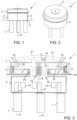
- Figures 1 to 3 illustrate an electric motor installed in a cycloidal propulsion unit as seen from the side in Figure 1 , from above in Figure 2 and in cross-section with cooling devices added in Figure 3 .
- the electric motor comprises a stator 2 which in this case is stationary installed within a hull 3 of a ship.
- a rotor 4 is rotatably arranged within the stator 2.
- the rotor 4 continues downwards as a rotary casing 5, which together with the rotor 4 rotates around a rotation axis 6 during operation.
- the rotation axis is in praxis vertically oriented.
- a lover part of the hollow rotary casing 5 is provided with blades 7, which are located in the water outside of the hull 3 and which together with the rotary casing rotate around the rotation axis 6.
- Each blade is additionally provided with a drive mechanism 8 which rotates a blade 7 separately in relation to the rotary casing 5 around a rotation axis 9. Due to the blade 7 specific drive mechanisms 8, each blade can be separately controlled to rotate in an optimal way. This makes it possible to drive and operate the ship as needed with the cycloidal propulsion unit. Consequently, the electric motor illustrated may be the main motor of the ship.
- the drive mechanisms may be implemented with suitable mechanical devices, such as gears and shafts, for instance. However, in the following explanation it will by way of example be assumed that the drive mechanisms 8 include electric motors driven by motor drives 10, such as frequency converters. Consequently, one electric motor for each blade 7.
- the motor drives 10 may be installed within the rotary casing 5, for instance.
- a challenge with an electric motor 1 of the illustrated type is cooling.
- a hybrid cooling solution is used to cool the electric motor 1.
- This hybrid cooling solution includes a cooling space 11 provided to the stator 2 for receiving and passing on a cooling fluid which cools the stator.
- the electric motor 1 is provided with an inlet 12 and an outlet 13 for receiving and passing on a cooling gas flow within the stator casing of the electric motor to cool at least the rotor 4.
- the inlet, outlets, fans, heat exchanger and cooling space are not illustrated in Figures 1 and 2 .
- the cooling space 11 through which a cooling fluid, such as water, circulates may be implemented as cooling jacket, for instance.
- the cooling space 11 may be implemented as a relatively high-volume annular container surrounding at least a part of the stator 2.
- the cooling space may be implemented as one or more pipes partly surrounding the stator.
- the cooling space may be implemented as a separate part surrounding and contacting the outer surface of the stator, or alternatively, as a part integrated into the outer walls of the stator casing. If integrated into the outer walls, the walls of the stator are at least partly hollow.
- a heat exchanger 14 is arranged to cool the gas flow, such as air flow, entering the electric motor 1 via the inlet 12.
- this heat exchanger is at least partially embedded into the illustrated electric motor. This ensures a space saving compact design.
- a heat exchanger is, however, not necessary in all embodiments.
- the heat exchanger is connected to a fluid circulation where cold fluid is used to cool the gas entering the electric motor 1. This gas flow circulates within the electric motor 1 where it comes into contact with at least the rotor 2 before exiting the electric motor via the outlet 13.
- two outlets have been provided byway of example, though in some implementations one outlet may be sufficient.
- both outlets 13 are provided with a fan 15, such as a centrifugal fan, though only one fan may be sufficient.
- a fan may not be needed at all, if the fluid flow may be generated somewhere else, such as by ventilation system of a building or a ship which is able to generate the gas flow needed for cooling. If a fan is included, this fan is preferably also at least partly embedded into the illustrated electric motor to provide a compact design.
- a closed loop for circulating the gas flow from the outlets 13 to the inlet 12 has been implemented by means of duct 21 which feeds the heated air flow from the outlets 13 via the heat exchanger 14 back into the electric motor 1.
- the gas flow may also cool the slip ring unit 16, the magnets 17 of the rotor and windings 18 of the stator 2.
- the main bearing 29, which rotatably supports the rotor and the rotary casing 5, is additionally to some extent cooled by means of the gas flow, though the main bearing may additionally be provided with a feed of lubrication, which also cools the main bearing.
- Efficient cooling of the magnets and windings is obtained in Figure 3 by conducting the gas flow through the rotor 4 via at least one opening 19. This opening is located between the magnets 17 and the rotation axis 6. Additionally, the gas flow is conducted through an annular gap 20 formed along an outer periphery of the rotor 4. This annular gap is shown in Figure 3 between the magnets 17 of the rotor 4 and the windings 18 of the stator 2. To ensure that the gas flow passes through the at least one opening 19 and the annular gap 20, a wall 23 has been provided to extend from a position in close proximity of the outer periphery of the rotor 4 to an upper wall part of the motor. This wall 23 prevents the gas flow from passing directly from the inlet to the outlet without flowing through the rotor 4 and the annular gap 20.
- the electric motor 1 When the electric motor 1 is used in a cycloidal propulsion unit with a rotary casing comprising drive mechanisms 8 for the blades, it is advantageous to conduct the air flow also through the rotary casing 5, as illustrated in Figure 3 . This makes it possible to ensure that the temperature in the space where the drive mechanisms are installed remains sufficiently low.
- the drive mechanisms 8 may additionally be cooled by a separate cooling fluid (not illustrated).
- a separate cooling fluid not illustrated.
- an opening 22 through the rotor 4 is provided in proximity of the rotation axis 6. This opening 22 facilitates gas flow from above, through the rotor 4 into the rotary casing 5 and back. This opening 22 may be very large to facilitate that maintenance personnel can enter the rotary casing 5 for service purposes via this opening 22.
- the inlet 12 is located close to the rotation axis 6, while the outlet or outlets 13 are located closer to the outer periphery of the rotor 4.
- the cooled gas flow entering the electric motor via the heat exchanger 14 close to the rotation axis 6 keeps the ambient temperature of the slip ring unit 16 and blade 7 drive mechanisms 8 lower.
- the direction of the gas flow may, however, be opposite with one or more inlets at the periphery of the rotor and one or more outlets close to the rotation axis.
- the heat exchanger 14 is located in the flow direction after the fan or fans 15. This is, however, only by way of examples. In other implementations the heat exchanger 14 may be located in the flow direction before the fan or fans 15. Still in some other implementations the gas flow may be such arranged that the gas is feed to an outer circulation on top of the electric motor and it flows downwards into the electric motor through the air gap 20 in the opposite direction compared to Figure 3 .
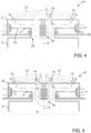
- Figure 4 illustrates a second embodiment of an electric motor 31.
- the embodiment of Figure 4 is very similar to the first embodiment explained in connection with Figures 1 - 3 . Therefore, in the following, the embodiment of Figure 4 is mainly explained by pointing out the differences between these embodiments.
- the rotary casing 5 and the devices located inside the rotary casing may be similar as has been explained in connection with Figure 3 .
- the gas flow may reach devices installed in the rotary casing 5 and provide cooling to them.
- Figure 5 illustrates a third embodiment of an electric motor.
- Figure 5 is very similar as the first embodiment explained in connection with Figures 1 - 3 and the second embodiment explained in connection with Figure 4 . Therefore, in the following, the embodiment of Figure 5 is mainly explained by pointing out the differences between these embodiments.
- the electric motor 41 is provided with two inlets 12 and also two heat exchangers 14 providing cooled gas flows into the electric motor 41. Additionally, to provide a closed circulation, two ducts 21 are provided to pass on the gas flow exiting the outlets 13 to the respective inlets 12.
- An advantage with such a solution which can be utilized also in the previously explained embodiments, is that the cooling capacity is increased. Consequently, a larger amount of cooling gas with a suitable temperature can be provided into the stator of the electric motor 41, as compared to the solutions illustrated in Figures 3 and 4 . Additionally, with such a solution the system becomes more redundant in case of a failure, such as in case of a fan motor failure. It also becomes possible to use smaller components (fans and/or heat exchangers) which saves space.
- the rotor 4 has a diameter D which is larger than the length L of the rotor in the direction of the rotation axis 6. This may also apply to all the other embodiments.
- the rotary casing 5 and the devices located inside the rotary casing may be similar as has been explained in connection with Figure 3 .
- the gas flow may reach devices installed in the rotary casing 5 and provide cooling to them.
- Figures 6 and 7 illustrate a fourth embodiment of an electric motor.
- the cooling gas flow passes the annular gap 20 between the rotor 54 and the stator 2 windings 18.
- the rotor 54 is provided with holes 55 along an outer periphery of the rotor 54.
- these holes 55 may form channels extending in a direction which is parallel or substantially parallel to the direction of the rotation axis 6.
- the electric motor is of a type where the rotor is not provided with magnets, such as in case of an induction motor
- the holes 55 may be as close as possible to the squirrel-cage of the induction motor, for instance.
- the thermal losses are significant and efficient cooling is required. This can be achieved with the structure illustrated in Figures 6 and 7 having the combination of the holes 55 in the rotor 52 and the annular gap between the rotor 54 and the stator 2. It may be beneficial to maximize the surface area of the holes by having the holes in two circles in close proximity to the squirrel-cage of the induction motor.
- Figure 8 illustrates a fifth embodiment of an electric motor.
- the embodiment of Figure 8 is very similar to the one explained in connection with Figures 1 - 3 . Therefore, in the following, the embodiment of Figure 8 is mainly explained by pointing out the differences between these embodiments.
- the electric motor 61 is installed in an enclosed room 63 (or space) of a ship or a building for instance.
- the room 63 is connected to a ventilation system of the ship or building via an outlet 64 and an inlet 65.
- a separate heat exchanger is therefore not needed at the electric motor to cool the gas flow, which is passed into the electric motor 61, as such a heat exchanger cooling the gas flow is provided to the ventilation system.
- One advantage of such a solution is that it saves space. In a a cycloidal propulsion unit, for instance, this may be a significant advantage.
- outlets 13 from the stator 62 are not provided in the upper part of the stator, but instead in the side of the stator. In this case two outlets are provided. A first outlet is provided directly below the stator windings 18 and a second outlet is provided directly above the stator windings 18. In this way the ends 66 of the stator windings will also be efficiently cooled. Due to the location of the lower outlet 13 below the stator winding 18, the gas flow will enter through the opening 19 into the space below the rotor 4. In some implementations it may be advantageous to have several outlets 13 in a row or rows around the side of the stator. In that case, this row or rows of outlets in the motor casing may be aligned with winding ends on both ends of the electric motor.
- outlets 13 are arranged in close proximity to the cooling space 11 which is provided with a cooling fluid circulation to cool the stator 62.
- the gas flow can be cooled partly by means of the cooling fluid circulation of the cooling space 11.
- Such cooling of the gas flow can also be obtained by reversing the gas flow within the electric motor 61. In that case the inlet 12 and the outlets 13 switch places. Consequently, the gas flow entering the electric motor via the inlets at the side of the stator is cooled by fins at the cooling space 11 just before entering the electric motor.
- the inlets or outlets can be provided to the side of the stator 62 as illustrated in Figure 8 also in the previously explained embodiments. In that case the electric motor can still be provided with the previously mentioned fans and heat exchangers, as explained in the previous embodiments.
- the rotary casing 5 and the devices located inside the rotary casing may be similar as has been explained in connection with Figure 3 .
- the gas flow may reach devices installed in the rotary casing 5 and provide cooling to them.
Landscapes
- Engineering & Computer Science (AREA)
- Power Engineering (AREA)
- Chemical & Material Sciences (AREA)
- Combustion & Propulsion (AREA)
- Mechanical Engineering (AREA)
- Ocean & Marine Engineering (AREA)
- Motor Or Generator Cooling System (AREA)
Abstract
This invention relates to an apparatus and to a method for cooling an electric motor. To obtain simple and sufficient cooling the electric motor is provided with a dual cooling system including a cooling space (11) provided to the stator (2) for receiving and passing on a cooling fluid which cools the stator, and an inlet (12) and an outlet (13) provided to the electric motor for receiving and passing on a cooling gas flow which cools at least the rotor (4) before exiting the electric motor.
Description
- This invention relates to a solution for cooling an electric motor. In the following the invention will by way of example be explained by referring to an electric motor of a cycloidal propulsion unit, though the cooling method can be utilized also for other electric motors.
- A problem with electric motors, such as with electric motors of a cycloidal propulsion unit, is to provide sufficient cooling to various parts of the electric motor. Sufficient cooling is essential, because the loading of an electric motor can be increased if a temperature rise can be avoided. Therefore, more power will be available from the electric motor without a need to increase the motor diameter or length if the cooling is efficient.
- An object of the present invention is to provide a solution ensuring efficient cooling for an electric motor. This object is achieved with the apparatus of
independent claim 1 and the method ofindependent claim 14. - An efficient dual cooling to an electric motor can be obtained by circulating a cooling fluid to the stator, and by cooling other components of the electric motor with a cooling gas flow, which from an inlet enters the electric motor and flows along a rotor before exiting the electric motor via an outlet. Such a solution ensures that the cooling is sufficiently efficient to ensure that a significant amount of power is available from the electric motor without a need to increase the size of the electric motor.
- Preferred embodiments of the invention are disclosed in the dependent claims.
- In the following apparatus and method will be described in closer detail by way of example and with reference to the attached drawings, in which
-
Figures 1 to 3 illustrate an electric motor installed in a cycloidal propulsion unit, -
Figure 4 illustrates a second embodiment of an electric motor, -
Figure 5 illustrates a third embodiment of an electric motor, -
Figure 6 and 7 illustrates a fourth embodiment of an electric motor, and -
Figure 8 illustrates a fifth embodiment of an electric motor. -
Figures 1 to 3 illustrate an electric motor installed in a cycloidal propulsion unit as seen from the side inFigure 1 , from above inFigure 2 and in cross-section with cooling devices added inFigure 3 . - The electric motor comprises a
stator 2 which in this case is stationary installed within ahull 3 of a ship. Arotor 4 is rotatably arranged within thestator 2. Therotor 4 continues downwards as arotary casing 5, which together with therotor 4 rotates around arotation axis 6 during operation. When the electric motor is installed in a cycloidal propulsion unit, the rotation axis is in praxis vertically oriented. - A lover part of the hollow
rotary casing 5 is provided withblades 7, which are located in the water outside of thehull 3 and which together with the rotary casing rotate around therotation axis 6. Each blade is additionally provided with adrive mechanism 8 which rotates ablade 7 separately in relation to therotary casing 5 around arotation axis 9. Due to theblade 7specific drive mechanisms 8, each blade can be separately controlled to rotate in an optimal way. This makes it possible to drive and operate the ship as needed with the cycloidal propulsion unit. Consequently, the electric motor illustrated may be the main motor of the ship. The drive mechanisms may be implemented with suitable mechanical devices, such as gears and shafts, for instance. However, in the following explanation it will by way of example be assumed that thedrive mechanisms 8 include electric motors driven bymotor drives 10, such as frequency converters. Consequently, one electric motor for eachblade 7. Themotor drives 10 may be installed within therotary casing 5, for instance. - A challenge with an
electric motor 1 of the illustrated type is cooling. In the illustrated example, a hybrid cooling solution is used to cool theelectric motor 1. This hybrid cooling solution includes acooling space 11 provided to thestator 2 for receiving and passing on a cooling fluid which cools the stator. In addition, theelectric motor 1 is provided with aninlet 12 and anoutlet 13 for receiving and passing on a cooling gas flow within the stator casing of the electric motor to cool at least therotor 4. For simplicity, the inlet, outlets, fans, heat exchanger and cooling space are not illustrated inFigures 1 and 2 . - The
cooling space 11 through which a cooling fluid, such as water, circulates may be implemented as cooling jacket, for instance. In that case thecooling space 11 may be implemented as a relatively high-volume annular container surrounding at least a part of thestator 2. Alternatively, depending on the implementation, the cooling space may be implemented as one or more pipes partly surrounding the stator. The cooling space may be implemented as a separate part surrounding and contacting the outer surface of the stator, or alternatively, as a part integrated into the outer walls of the stator casing. If integrated into the outer walls, the walls of the stator are at least partly hollow. - In
Figure 3 it is by way of example assumed that aheat exchanger 14 is arranged to cool the gas flow, such as air flow, entering theelectric motor 1 via theinlet 12. Preferably, this heat exchanger is at least partially embedded into the illustrated electric motor. This ensures a space saving compact design. A heat exchanger is, however, not necessary in all embodiments. InFigure 3 the heat exchanger is connected to a fluid circulation where cold fluid is used to cool the gas entering theelectric motor 1. This gas flow circulates within theelectric motor 1 where it comes into contact with at least therotor 2 before exiting the electric motor via theoutlet 13. In the illustrated example two outlets have been provided byway of example, though in some implementations one outlet may be sufficient. It is also illustrated by way of example inFigure 3 that bothoutlets 13 are provided with afan 15, such as a centrifugal fan, though only one fan may be sufficient. In some implementations a fan may not be needed at all, if the fluid flow may be generated somewhere else, such as by ventilation system of a building or a ship which is able to generate the gas flow needed for cooling. If a fan is included, this fan is preferably also at least partly embedded into the illustrated electric motor to provide a compact design. - In
Figure 3 a closed loop for circulating the gas flow from theoutlets 13 to theinlet 12 has been implemented by means ofduct 21 which feeds the heated air flow from theoutlets 13 via theheat exchanger 14 back into theelectric motor 1. In addition to cooling therotor 2, the gas flow may also cool theslip ring unit 16, themagnets 17 of the rotor andwindings 18 of thestator 2. Themain bearing 29, which rotatably supports the rotor and therotary casing 5, is additionally to some extent cooled by means of the gas flow, though the main bearing may additionally be provided with a feed of lubrication, which also cools the main bearing. - Efficient cooling of the magnets and windings is obtained in
Figure 3 by conducting the gas flow through therotor 4 via at least one opening 19. This opening is located between themagnets 17 and therotation axis 6. Additionally, the gas flow is conducted through anannular gap 20 formed along an outer periphery of therotor 4. This annular gap is shown inFigure 3 between themagnets 17 of therotor 4 and thewindings 18 of thestator 2. To ensure that the gas flow passes through the at least one opening 19 and theannular gap 20, awall 23 has been provided to extend from a position in close proximity of the outer periphery of therotor 4 to an upper wall part of the motor. Thiswall 23 prevents the gas flow from passing directly from the inlet to the outlet without flowing through therotor 4 and theannular gap 20. - In case another type of electric motor is utilized in the embodiment of
Figures 1 - 3 or in the other embodiments, such as a induction motor with a wound type or squirrel-cage type induction rotor, no magnets are needed in the rotor. Also, in that case it is advantageous to conduct the gas flow through theannular gap 20 formed along the outer periphery of therotor 4, as the gas flow will in that case cool the wound or squirrel-cage of the rotor. - When the
electric motor 1 is used in a cycloidal propulsion unit with a rotary casing comprisingdrive mechanisms 8 for the blades, it is advantageous to conduct the air flow also through therotary casing 5, as illustrated inFigure 3 . This makes it possible to ensure that the temperature in the space where the drive mechanisms are installed remains sufficiently low. In some installations, thedrive mechanisms 8 may additionally be cooled by a separate cooling fluid (not illustrated). However, also in that case it is advantageous to ensure that the temperature in the inner space of therotary casing 5 is at an acceptable level by means of the cooling gas flow, as it will be easier for the fluid cooling to keep the most critical components in the rotary casing at an adequate temperature. - In
Figure 3 anopening 22 through therotor 4 is provided in proximity of therotation axis 6. Thisopening 22 facilitates gas flow from above, through therotor 4 into therotary casing 5 and back. Thisopening 22 may be very large to facilitate that maintenance personnel can enter therotary casing 5 for service purposes via thisopening 22. - In
Figure 3 theinlet 12 is located close to therotation axis 6, while the outlet oroutlets 13 are located closer to the outer periphery of therotor 4. One advantage with this is that the cooled gas flow entering the electric motor via theheat exchanger 14 close to therotation axis 6 keeps the ambient temperature of theslip ring unit 16 andblade 7drive mechanisms 8 lower. In some installations the direction of the gas flow may, however, be opposite with one or more inlets at the periphery of the rotor and one or more outlets close to the rotation axis. - In
Figure 3 theheat exchanger 14 is located in the flow direction after the fan orfans 15. This is, however, only by way of examples. In other implementations theheat exchanger 14 may be located in the flow direction before the fan orfans 15. Still in some other implementations the gas flow may be such arranged that the gas is feed to an outer circulation on top of the electric motor and it flows downwards into the electric motor through theair gap 20 in the opposite direction compared toFigure 3 . -
Figure 4 illustrates a second embodiment of anelectric motor 31. The embodiment ofFigure 4 is very similar to the first embodiment explained in connection withFigures 1 - 3 . Therefore, in the following, the embodiment ofFigure 4 is mainly explained by pointing out the differences between these embodiments. - In
Figure 4 the gas flow from theinlet 12 to theoutlet 13 is conducted differently. Thewall 23 shown inFigure 3 is missing inFigure 4 . Due to this there is nothing forcing the gas flow to pass via the openings 19 (if provided) andannular gap 20 of therotor 4. Instead, the gas flow passes from the space above therotor 4 to the space below the rotor along theslip ring unit 16 in proximity of therotation axis 6 via theopening 22. However, if airflow through theopenings 19 to the space below therotor 4 is preferred, this may be in some implementations be obtained by reversing the flow direction and by locatingopenings 13 aboveopenings 19. In that case the gas flow enters the electric motor via theopenings 13 and and a part of the gas flow continues viaopenings 19 to the space below therotor 4. - If the
electric motor 31 is used in a cycloidal propulsion unit, therotary casing 5 and the devices located inside the rotary casing may be similar as has been explained in connection withFigure 3 . For simplicity, only the upper part of the rotary casing is shown inFigure 4 , though also in this second embodiment the gas flow may reach devices installed in therotary casing 5 and provide cooling to them. -
Figure 5 illustrates a third embodiment of an electric motor.Figure 5 is very similar as the first embodiment explained in connection withFigures 1 - 3 and the second embodiment explained in connection withFigure 4 . Therefore, in the following, the embodiment ofFigure 5 is mainly explained by pointing out the differences between these embodiments. - In
Figure 5 theelectric motor 41 is provided with twoinlets 12 and also twoheat exchangers 14 providing cooled gas flows into theelectric motor 41. Additionally, to provide a closed circulation, twoducts 21 are provided to pass on the gas flow exiting theoutlets 13 to therespective inlets 12. An advantage with such a solution, which can be utilized also in the previously explained embodiments, is that the cooling capacity is increased. Consequently, a larger amount of cooling gas with a suitable temperature can be provided into the stator of theelectric motor 41, as compared to the solutions illustrated inFigures 3 and4 . Additionally, with such a solution the system becomes more redundant in case of a failure, such as in case of a fan motor failure. It also becomes possible to use smaller components (fans and/or heat exchangers) which saves space. - As can be seen from
Figure 5 , therotor 4 has a diameter D which is larger than the length L of the rotor in the direction of therotation axis 6. This may also apply to all the other embodiments. - If the
electric motor 41 is used in a cycloidal propulsion unit, therotary casing 5 and the devices located inside the rotary casing may be similar as has been explained in connection withFigure 3 . For simplicity, only the upper part of the rotary casing is shown inFigure 5 , though also in this second embodiment the gas flow may reach devices installed in therotary casing 5 and provide cooling to them. -
Figures 6 and 7 illustrate a fourth embodiment of an electric motor. - The embodiment of
Figures 6 and 7 is very similar to the first embodiment explained in connection withFigures 1 - 3 . Therefore, in the following, the embodiment ofFigures 6 and 7 is mainly explained by pointing out the differences between these embodiments. - In
Figure 6 only the upper right part of the electric motor is illustrated to provide an enlarged view of the area around theannular gap 20 between therotor 54magnets 17 and thestator 2windings 18.Figure 7 illustrates an enlarged view of the same area as seen from above. - Similarly, as in the embodiment of
Figure 3 , also inFigures 6 and 7 the cooling gas flow passes theannular gap 20 between therotor 54 and thestator 2windings 18. However, to still improve cooling of the rotor, therotor 54 is provided withholes 55 along an outer periphery of therotor 54. In praxis theseholes 55 may form channels extending in a direction which is parallel or substantially parallel to the direction of therotation axis 6. - In
Figures 6 and 7 it is by way of example assumed that electric motor is of a type where therotor 54 is provided withmagnets 17. In that that case theholes 55 or channels are provided through the rotor at themagnets 17. In praxis theseholes 55 are provided in close proximity to the magnets, between themagnets 17 and theopenings 19. With such a solution, a cooling flow which flows in the direction of therotation axis 6 is obtained on two sides of themagnets 17, via theannular gap 20 and via theholes 55 at the magnets. This makes the cooling much more efficient. - However, in case the electric motor is of a type where the rotor is not provided with magnets, such as in case of an induction motor, it is still beneficial to have the illustrated
holes 55 close to the outer periphery of therotor 54 to provide a cooling flow through theholes 55 in the direction of therotation axis 6. In that case theholes 55 may be as close as possible to the squirrel-cage of the induction motor, for instance. In particular for low price induction motors, the thermal losses are significant and efficient cooling is required. This can be achieved with the structure illustrated inFigures 6 and 7 having the combination of theholes 55 in the rotor 52 and the annular gap between therotor 54 and thestator 2. It may be beneficial to maximize the surface area of the holes by having the holes in two circles in close proximity to the squirrel-cage of the induction motor. -
Figure 8 illustrates a fifth embodiment of an electric motor. The embodiment ofFigure 8 is very similar to the one explained in connection withFigures 1 - 3 . Therefore, in the following, the embodiment ofFigure 8 is mainly explained by pointing out the differences between these embodiments. - In
Figure 8 theelectric motor 61 is installed in an enclosed room 63 (or space) of a ship or a building for instance. Theroom 63 is connected to a ventilation system of the ship or building via anoutlet 64 and aninlet 65. A separate heat exchanger is therefore not needed at the electric motor to cool the gas flow, which is passed into theelectric motor 61, as such a heat exchanger cooling the gas flow is provided to the ventilation system. One advantage of such a solution is that it saves space. In a a cycloidal propulsion unit, for instance, this may be a significant advantage. - In
Figure 8 it is by way of example assumed that theelectric motor 61 is provided with afan 15 generating a gas flow into theelectric motor 61. However, this fan can be eliminated in case the air flow from theinlet 65 to the room provides a sufficiently strong air flow and thisinlet 65 can be directly connected to theinlet 12 of theelectric motor 61. - In
Figure 8 theoutlets 13 from thestator 62 are not provided in the upper part of the stator, but instead in the side of the stator. In this case two outlets are provided. A first outlet is provided directly below thestator windings 18 and a second outlet is provided directly above thestator windings 18. In this way the ends 66 of the stator windings will also be efficiently cooled. Due to the location of thelower outlet 13 below the stator winding 18, the gas flow will enter through theopening 19 into the space below therotor 4. In some implementations it may be advantageous to haveseveral outlets 13 in a row or rows around the side of the stator. In that case, this row or rows of outlets in the motor casing may be aligned with winding ends on both ends of the electric motor. - In
Figure 8 outlets 13 are arranged in close proximity to the coolingspace 11 which is provided with a cooling fluid circulation to cool thestator 62. This makes it possible to provide cooling fins (not illustrated) to extend from the coolingspace 11 into the gas flow passing via theoutlets 13. In this way, the gas flow can be cooled partly by means of the cooling fluid circulation of the coolingspace 11. Such cooling of the gas flow can also be obtained by reversing the gas flow within theelectric motor 61. In that case theinlet 12 and theoutlets 13 switch places. Consequently, the gas flow entering the electric motor via the inlets at the side of the stator is cooled by fins at the coolingspace 11 just before entering the electric motor. - The inlets or outlets can be provided to the side of the
stator 62 as illustrated inFigure 8 also in the previously explained embodiments. In that case the electric motor can still be provided with the previously mentioned fans and heat exchangers, as explained in the previous embodiments. - If the
electric motor 61 is used in a cycloidal propulsion unit, therotary casing 5 and the devices located inside the rotary casing may be similar as has been explained in connection withFigure 3 . For simplicity, only the upper part of the rotary casing is shown inFigure 8 , though also in this second embodiment the gas flow may reach devices installed in therotary casing 5 and provide cooling to them. - It is to be understood that the above description and the accompanying figures are only intended to illustrate the present invention. It will be obvious to a person skilled in the art that the invention can be varied and modified without departing from the scope of the invention.
Claims (16)
- Apparatus comprising:
a cycloidal propulsion unit with an electric motor (1, 31, 41, 51, 61) having a stator (2, 32, 62) and a rotor (4, 54), characterized in that the electric motor is provided with a dual cooling system including:a cooling space (11) provided to the stator (2, 32, 62) for receiving and passing on a cooling fluid which cools the stator, andan inlet (12) and an outlet (13) provided to the electric motor for receiving and passing on a cooling gas flow which cools at least the rotor (4, 54) before exiting the electric motor. - The apparatus according to claim 1, wherein the apparatus comprises a fan (15) circulating the cooling gas flow flowing from the inlet (12) to the outlet (13).
- The apparatus according to claim 1 or 2, wherein the apparatus comprises a heat exchanger (14) through which said cooling gas flow passes, the heat exchanger (14) receiving and passing on a cooling fluid, which in the heat exchanger cools the cooling gas flow.
- The apparatus according to one of claims 1 to 3, wherein an annular gap (20) is provided between an outer periphery of the the rotor (4, 54) and the stator (2) and the cooling gas flow between the inlet (12) and the outlet (13) is directed to pass via the annular gap (20).
- The apparatus according to one of claims 1 to 4, wherein the gas flow is directed to flow through at least one opening (19, 22) in the the rotor (4, 54) before exiting the electric motor (1).
- The apparatus according to one of claims 1 to 5, whereinthe rotor (54) is provided with holes (55) along an outer periphery of the rotor and is configured to rotate around a rotation axis (6), andthe cooling gas flow is directed to flow between the inlet (12) and the outlet (13) by passing through the holes (55) in the rotor (54) which are provided in close proximity to the outer periphery of the rotor (54).
- The apparatus according to one of claims 1 to 6, wherein one of the inlet (12) and outlet (13) is provided in proximity of the cooling space (11) such that cooling fluid in the cooling space (11) cools the gas flow entering of exiting the electric motor (61).
- The apparatus according to one of claims 1 to 7, wherein the cooling space (11) provided to the stator (2, 32, 62) includes a cooling jacket at least partially surrounding the stator (2, 32, 62).
- The apparatus according to one of claims 1 to 8, wherein the cooling space (11) provided to the stator (2, 32, 62) includes cooling pipes provided to the stator (2, 32, 62).
- The apparatus according to one of claims 1 to 9, whereinthe cycloidal propulsion unit comprises a rotary casing (5) arranged coaxially with the rotor (4, 54) to rotate with the rotor around a vertical rotation axis (6) and as an extension to the stator (2, 32, 62), andthe rotary casing (5) comprises a drive mechanism (8) arranged to rotate blades (7) of the cycloidal propulsion unit which protrude outward from the rotary casing (5) in a direction away from the rotor (4, 54).
- The apparatus according to claim 10, wherein at least a part of the cooling gas flow is directed to flow from the inlet (12) via the rotary casing (5) to the outlet (13) for cooling the drive mechanism.
- The apparatus according to one of claims 10 to 11, wherein the the stator (4, 54) is provided with an opening (22) providing service personnel access to enter the rotary casing (5) by passing through the stator.
- The apparatus according to one of claims 1 to 12, wherein the rotor (4, 54) has a diameter (D) which is larger than a length (L) of the rotor in the direction of the rotation axis (6).
- A method for cooling an electric motor (1, 31, 41, 51, 61) having a stator (2, 32, 62) and a rotor (4, 54), characterized in that the method comprises providing dual cooling by:circulating a cooling fluid to the stator (2, 32, 62) for cooling the stator, andpassing on a cooling gas flow via an inlet (12) into the electric motor (1, 31, 41, 51, 61), through the rotor (4, 54) and further out of the electric motor via an outlet (13).
- The method according to claim 14, wherein the cooling gas flow is directed to pass via an annular gap (20) provided between the rotor and the stator (2) along an outer periphery of the rotor (4, 54).
- The method according to one of claims 14 to 15, wherein the cooling gas flow is directed to pass via holes (55) provided in the rotor (54) along an outer periphery of the rotor (54).
Priority Applications (5)
| Application Number | Priority Date | Filing Date | Title |
|---|---|---|---|
| EP23182600.9A EP4485761A1 (en) | 2023-06-30 | 2023-06-30 | Apparatus and method for cooling |
| US18/751,456 US20250007354A1 (en) | 2023-06-30 | 2024-06-24 | Apparatus and method for cooling |
| KR1020240083297A KR102946765B1 (en) | 2023-06-30 | 2024-06-26 | Apparatus and method for cooling |
| CN202410848445.9A CN119231841A (en) | 2023-06-30 | 2024-06-27 | Device and method for cooling |
| JP2024104651A JP7823119B2 (en) | 2023-06-30 | 2024-06-28 | Apparatus and method for cooling |
Applications Claiming Priority (1)
| Application Number | Priority Date | Filing Date | Title |
|---|---|---|---|
| EP23182600.9A EP4485761A1 (en) | 2023-06-30 | 2023-06-30 | Apparatus and method for cooling |
Publications (1)
| Publication Number | Publication Date |
|---|---|
| EP4485761A1 true EP4485761A1 (en) | 2025-01-01 |
Family
ID=87060487
Family Applications (1)
| Application Number | Title | Priority Date | Filing Date |
|---|---|---|---|
| EP23182600.9A Pending EP4485761A1 (en) | 2023-06-30 | 2023-06-30 | Apparatus and method for cooling |
Country Status (5)
| Country | Link |
|---|---|
| US (1) | US20250007354A1 (en) |
| EP (1) | EP4485761A1 (en) |
| JP (1) | JP7823119B2 (en) |
| KR (1) | KR102946765B1 (en) |
| CN (1) | CN119231841A (en) |
Citations (3)
| Publication number | Priority date | Publication date | Assignee | Title |
|---|---|---|---|---|
| DE19919040A1 (en) * | 1999-02-25 | 2000-09-07 | Helmuth Beneke | Electric machine, in particular three-phase machine |
| DE10307813B4 (en) * | 2003-02-24 | 2006-05-24 | Siemens Ag | Electric machine |
| US20220048607A1 (en) * | 2018-12-14 | 2022-02-17 | Abb Oy | Cycloidal Marine Propulsion Unit And A Marine Vessel Equipped Therewith |
Family Cites Families (11)
| Publication number | Priority date | Publication date | Assignee | Title |
|---|---|---|---|---|
| JPS5484203A (en) * | 1977-12-16 | 1979-07-05 | Hitachi Ltd | Revolving electric machine |
| JPS56102946U (en) * | 1980-01-10 | 1981-08-12 | ||
| GB2289992B (en) * | 1994-05-24 | 1998-05-20 | Gec Alsthom Ltd | Improvements in or relating to cooling arrangements in rotating electrical machines |
| GB9721850D0 (en) * | 1997-10-16 | 1997-12-17 | Normalair Garrett Ltd | Motor cooling |
| US6700235B1 (en) * | 1999-11-02 | 2004-03-02 | Franklin Electric Co. | Enhanced cooling apparatus and method for rotating machinery |
| US8395288B2 (en) * | 2005-09-21 | 2013-03-12 | Calnetix Technologies, L.L.C. | Electric machine with centrifugal impeller |
| JP2014140288A (en) * | 2012-12-20 | 2014-07-31 | Yaskawa Electric Corp | Rotary electric machine and housing of the same |
| JP6860456B2 (en) * | 2017-05-09 | 2021-04-14 | 株式会社神戸製鋼所 | Compressor |
| JP6624223B2 (en) * | 2018-03-09 | 2019-12-25 | 株式会社明電舎 | Rotating electric machine |
| WO2020120827A1 (en) * | 2018-12-14 | 2020-06-18 | Abb Oy | Marine propulsion unit |
| FR3106453B1 (en) * | 2020-01-20 | 2021-12-10 | Safran Electrical & Power | Cooling system for a drive unit with several electric machines. |
-
2023
- 2023-06-30 EP EP23182600.9A patent/EP4485761A1/en active Pending
-
2024
- 2024-06-24 US US18/751,456 patent/US20250007354A1/en active Pending
- 2024-06-26 KR KR1020240083297A patent/KR102946765B1/en active Active
- 2024-06-27 CN CN202410848445.9A patent/CN119231841A/en active Pending
- 2024-06-28 JP JP2024104651A patent/JP7823119B2/en active Active
Patent Citations (3)
| Publication number | Priority date | Publication date | Assignee | Title |
|---|---|---|---|---|
| DE19919040A1 (en) * | 1999-02-25 | 2000-09-07 | Helmuth Beneke | Electric machine, in particular three-phase machine |
| DE10307813B4 (en) * | 2003-02-24 | 2006-05-24 | Siemens Ag | Electric machine |
| US20220048607A1 (en) * | 2018-12-14 | 2022-02-17 | Abb Oy | Cycloidal Marine Propulsion Unit And A Marine Vessel Equipped Therewith |
Also Published As
| Publication number | Publication date |
|---|---|
| CN119231841A (en) | 2024-12-31 |
| JP7823119B2 (en) | 2026-03-03 |
| JP2025010022A (en) | 2025-01-20 |
| US20250007354A1 (en) | 2025-01-02 |
| KR102946765B1 (en) | 2026-04-02 |
| KR20250003329A (en) | 2025-01-07 |
Similar Documents
| Publication | Publication Date | Title |
|---|---|---|
| JP6483158B2 (en) | Ship pod propulsion unit | |
| US7160086B2 (en) | Rotary machine cooling system | |
| US20130307357A1 (en) | Permanent Magnet Motor with a Closed Cooling System | |
| EP1415382B1 (en) | Electric propulsion units | |
| KR20090121328A (en) | Cooling of electric machine | |
| CN101517865A (en) | Electrical machine with an internally cooled rotor | |
| JP2015027871A (en) | Ship's propulsion unit | |
| WO2018196003A1 (en) | Motor ventilation structure and motor | |
| WO2023246048A1 (en) | Outer rotor motor | |
| KR20190087708A (en) | cooling structure of a motor with a thermosiphone | |
| CN109936257B (en) | Electric motor comprising an exchanger and a plurality of cooling circuits | |
| KR102003981B1 (en) | double cooling structure of a turbo motor with two-direction impeller | |
| EP4485761A1 (en) | Apparatus and method for cooling | |
| CN1044018A (en) | Bore pack exciter cooling system | |
| JPH09285072A (en) | High speed motor | |
| JP2008125172A (en) | Vehicle drive device | |
| KR20190087706A (en) | double cooling structure of a motor | |
| US3207934A (en) | Electric motor with improved cooling means | |
| EP2950430B1 (en) | Electrical machine system and wind power generating system | |
| HU223700B1 (en) | Liquid-cooled electric machine | |
| RU2717838C1 (en) | Multi-rotor electric machine with combined cooling system | |
| JP2008038762A (en) | Air blower for cooling tower | |
| WO2022086459A1 (en) | A liquid - cooled cooling method for electric motors and alternators | |
| KR102702974B1 (en) | Cooling System For Motor | |
| JPH056421B2 (en) |
Legal Events
| Date | Code | Title | Description |
|---|---|---|---|
| PUAI | Public reference made under article 153(3) epc to a published international application that has entered the european phase |
Free format text: ORIGINAL CODE: 0009012 |
|
| STAA | Information on the status of an ep patent application or granted ep patent |
Free format text: STATUS: THE APPLICATION HAS BEEN PUBLISHED |
|
| AK | Designated contracting states |
Kind code of ref document: A1 Designated state(s): AL AT BE BG CH CY CZ DE DK EE ES FI FR GB GR HR HU IE IS IT LI LT LU LV MC ME MK MT NL NO PL PT RO RS SE SI SK SM TR |
|
| STAA | Information on the status of an ep patent application or granted ep patent |
Free format text: STATUS: REQUEST FOR EXAMINATION WAS MADE |
|
| 17P | Request for examination filed |
Effective date: 20250623 |