EP4485734A1 - Power converter, power system, and control method for power converter - Google Patents
Power converter, power system, and control method for power converter Download PDFInfo
- Publication number
- EP4485734A1 EP4485734A1 EP22928819.6A EP22928819A EP4485734A1 EP 4485734 A1 EP4485734 A1 EP 4485734A1 EP 22928819 A EP22928819 A EP 22928819A EP 4485734 A1 EP4485734 A1 EP 4485734A1
- Authority
- EP
- European Patent Office
- Prior art keywords
- electric power
- current
- electric
- reference function
- alternating
- Prior art date
- Legal status (The legal status is an assumption and is not a legal conclusion. Google has not performed a legal analysis and makes no representation as to the accuracy of the status listed.)
- Pending
Links
Images


Classifications
-
- H—ELECTRICITY
- H02—GENERATION; CONVERSION OR DISTRIBUTION OF ELECTRIC POWER
- H02J—ELECTRIC POWER NETWORKS; CIRCUIT ARRANGEMENTS OR SYSTEMS FOR SUPPLYING OR DISTRIBUTING ELECTRIC POWER; SYSTEMS FOR STORING ELECTRIC ENERGY
- H02J13/00—Circuit arrangements for providing remote monitoring or remote control of equipment in a power distribution network
- H02J13/13—Circuit arrangements for providing remote monitoring or remote control of equipment in a power distribution network characterised by the transmission of data to equipment in the power network
-
- H—ELECTRICITY
- H02—GENERATION; CONVERSION OR DISTRIBUTION OF ELECTRIC POWER
- H02M—APPARATUS FOR CONVERSION BETWEEN AC AND AC, BETWEEN AC AND DC, OR BETWEEN DC AND DC, AND FOR USE WITH MAINS OR SIMILAR POWER SUPPLY SYSTEMS; CONVERSION OF DC OR AC INPUT POWER INTO SURGE OUTPUT POWER; CONTROL OR REGULATION THEREOF
- H02M1/00—Details of apparatus for conversion
- H02M1/0003—Details of control, feedback or regulation circuits
- H02M1/0025—Arrangements for modifying reference values, feedback values or error values in the control loop of a converter
-
- H—ELECTRICITY
- H02—GENERATION; CONVERSION OR DISTRIBUTION OF ELECTRIC POWER
- H02M—APPARATUS FOR CONVERSION BETWEEN AC AND AC, BETWEEN AC AND DC, OR BETWEEN DC AND DC, AND FOR USE WITH MAINS OR SIMILAR POWER SUPPLY SYSTEMS; CONVERSION OF DC OR AC INPUT POWER INTO SURGE OUTPUT POWER; CONTROL OR REGULATION THEREOF
- H02M1/00—Details of apparatus for conversion
- H02M1/0095—Hybrid converter topologies, e.g. NPC mixed with flying capacitor, thyristor converter mixed with MMC or charge pump mixed with buck
-
- G—PHYSICS
- G06—COMPUTING OR CALCULATING; COUNTING
- G06Q—INFORMATION AND COMMUNICATION TECHNOLOGY [ICT] SPECIALLY ADAPTED FOR ADMINISTRATIVE, COMMERCIAL, FINANCIAL, MANAGERIAL OR SUPERVISORY PURPOSES; SYSTEMS OR METHODS SPECIALLY ADAPTED FOR ADMINISTRATIVE, COMMERCIAL, FINANCIAL, MANAGERIAL OR SUPERVISORY PURPOSES, NOT OTHERWISE PROVIDED FOR
- G06Q50/00—Information and communication technology [ICT] specially adapted for implementation of business processes of specific business sectors, e.g. utilities or tourism
- G06Q50/06—Energy or water supply
-
- H—ELECTRICITY
- H02—GENERATION; CONVERSION OR DISTRIBUTION OF ELECTRIC POWER
- H02J—ELECTRIC POWER NETWORKS; CIRCUIT ARRANGEMENTS OR SYSTEMS FOR SUPPLYING OR DISTRIBUTING ELECTRIC POWER; SYSTEMS FOR STORING ELECTRIC ENERGY
- H02J1/00—Circuit arrangements for DC mains or DC distribution networks
- H02J1/10—Parallel operation of DC sources
- H02J1/102—Parallel operation of DC sources being switching converters
-
- H—ELECTRICITY
- H02—GENERATION; CONVERSION OR DISTRIBUTION OF ELECTRIC POWER
- H02J—ELECTRIC POWER NETWORKS; CIRCUIT ARRANGEMENTS OR SYSTEMS FOR SUPPLYING OR DISTRIBUTING ELECTRIC POWER; SYSTEMS FOR STORING ELECTRIC ENERGY
- H02J1/00—Circuit arrangements for DC mains or DC distribution networks
- H02J1/10—Parallel operation of DC sources
- H02J1/106—Parallel operation of DC sources for load balancing, symmetrisation, or sharing
-
- H—ELECTRICITY
- H02—GENERATION; CONVERSION OR DISTRIBUTION OF ELECTRIC POWER
- H02J—ELECTRIC POWER NETWORKS; CIRCUIT ARRANGEMENTS OR SYSTEMS FOR SUPPLYING OR DISTRIBUTING ELECTRIC POWER; SYSTEMS FOR STORING ELECTRIC ENERGY
- H02J3/00—Circuit arrangements for AC mains or AC distribution networks
- H02J3/12—Arrangements for adjusting voltage in AC networks by changing a characteristic of the network load
- H02J3/14—Arrangements for adjusting voltage in AC networks by changing a characteristic of the network load by switching loads on to, or off from, the networks, e.g. progressively balanced loading
-
- H—ELECTRICITY
- H02—GENERATION; CONVERSION OR DISTRIBUTION OF ELECTRIC POWER
- H02J—ELECTRIC POWER NETWORKS; CIRCUIT ARRANGEMENTS OR SYSTEMS FOR SUPPLYING OR DISTRIBUTING ELECTRIC POWER; SYSTEMS FOR STORING ELECTRIC ENERGY
- H02J3/00—Circuit arrangements for AC mains or AC distribution networks
- H02J3/28—Arrangements for balancing of the load in networks by storage of energy
- H02J3/32—Arrangements for balancing of the load in networks by storage of energy using batteries or super capacitors with converting means
-
- H—ELECTRICITY
- H02—GENERATION; CONVERSION OR DISTRIBUTION OF ELECTRIC POWER
- H02J—ELECTRIC POWER NETWORKS; CIRCUIT ARRANGEMENTS OR SYSTEMS FOR SUPPLYING OR DISTRIBUTING ELECTRIC POWER; SYSTEMS FOR STORING ELECTRIC ENERGY
- H02J3/00—Circuit arrangements for AC mains or AC distribution networks
- H02J3/38—Arrangements for feeding a single network from two or more generators or sources in parallel; Arrangements for feeding already energised networks from additional generators or sources in parallel
- H02J3/381—Dispersed generators
-
- H—ELECTRICITY
- H02—GENERATION; CONVERSION OR DISTRIBUTION OF ELECTRIC POWER
- H02M—APPARATUS FOR CONVERSION BETWEEN AC AND AC, BETWEEN AC AND DC, OR BETWEEN DC AND DC, AND FOR USE WITH MAINS OR SIMILAR POWER SUPPLY SYSTEMS; CONVERSION OF DC OR AC INPUT POWER INTO SURGE OUTPUT POWER; CONTROL OR REGULATION THEREOF
- H02M1/00—Details of apparatus for conversion
- H02M1/0067—Converter structures employing plural converter units, other than for parallel operation of the units on a single load
- H02M1/007—Plural converter units in cascade
-
- H—ELECTRICITY
- H02—GENERATION; CONVERSION OR DISTRIBUTION OF ELECTRIC POWER
- H02M—APPARATUS FOR CONVERSION BETWEEN AC AND AC, BETWEEN AC AND DC, OR BETWEEN DC AND DC, AND FOR USE WITH MAINS OR SIMILAR POWER SUPPLY SYSTEMS; CONVERSION OF DC OR AC INPUT POWER INTO SURGE OUTPUT POWER; CONTROL OR REGULATION THEREOF
- H02M7/00—Conversion of AC power input into DC power output; Conversion of DC power input into AC power output
- H02M7/02—Conversion of AC power input into DC power output without possibility of reversal
- H02M7/04—Conversion of AC power input into DC power output without possibility of reversal by static converters
- H02M7/12—Conversion of AC power input into DC power output without possibility of reversal by static converters using discharge tubes with control electrode or semiconductor devices with control electrode
- H02M7/21—Conversion of AC power input into DC power output without possibility of reversal by static converters using discharge tubes with control electrode or semiconductor devices with control electrode using devices of a triode or transistor type requiring continuous application of a control signal
- H02M7/217—Conversion of AC power input into DC power output without possibility of reversal by static converters using discharge tubes with control electrode or semiconductor devices with control electrode using devices of a triode or transistor type requiring continuous application of a control signal using semiconductor devices only
-
- H—ELECTRICITY
- H02—GENERATION; CONVERSION OR DISTRIBUTION OF ELECTRIC POWER
- H02M—APPARATUS FOR CONVERSION BETWEEN AC AND AC, BETWEEN AC AND DC, OR BETWEEN DC AND DC, AND FOR USE WITH MAINS OR SIMILAR POWER SUPPLY SYSTEMS; CONVERSION OF DC OR AC INPUT POWER INTO SURGE OUTPUT POWER; CONTROL OR REGULATION THEREOF
- H02M7/00—Conversion of AC power input into DC power output; Conversion of DC power input into AC power output
- H02M7/42—Conversion of DC power input into AC power output without possibility of reversal
- H02M7/44—Conversion of DC power input into AC power output without possibility of reversal by static converters
- H02M7/48—Conversion of DC power input into AC power output without possibility of reversal by static converters using discharge tubes with control electrode or semiconductor devices with control electrode
- H02M7/53—Conversion of DC power input into AC power output without possibility of reversal by static converters using discharge tubes with control electrode or semiconductor devices with control electrode using devices of a triode or transistor type requiring continuous application of a control signal
- H02M7/537—Conversion of DC power input into AC power output without possibility of reversal by static converters using discharge tubes with control electrode or semiconductor devices with control electrode using devices of a triode or transistor type requiring continuous application of a control signal using semiconductor devices only, e.g. single switched pulse inverters
- H02M7/539—Conversion of DC power input into AC power output without possibility of reversal by static converters using discharge tubes with control electrode or semiconductor devices with control electrode using devices of a triode or transistor type requiring continuous application of a control signal using semiconductor devices only, e.g. single switched pulse inverters with automatic control of output wave form or frequency
- H02M7/5395—Conversion of DC power input into AC power output without possibility of reversal by static converters using discharge tubes with control electrode or semiconductor devices with control electrode using devices of a triode or transistor type requiring continuous application of a control signal using semiconductor devices only, e.g. single switched pulse inverters with automatic control of output wave form or frequency by pulse-width modulation
-
- H—ELECTRICITY
- H02—GENERATION; CONVERSION OR DISTRIBUTION OF ELECTRIC POWER
- H02J—ELECTRIC POWER NETWORKS; CIRCUIT ARRANGEMENTS OR SYSTEMS FOR SUPPLYING OR DISTRIBUTING ELECTRIC POWER; SYSTEMS FOR STORING ELECTRIC ENERGY
- H02J2101/00—Supply or distribution of decentralised, dispersed or local electric power generation
- H02J2101/20—Dispersed power generation using renewable energy sources
- H02J2101/22—Solar energy
- H02J2101/24—Photovoltaics
Definitions
- the present invention relates to electric power converters, electric power systems, and methods of controlling the electric power converters.
- a system disclosed in Patent Literature 1 is one of systems that convert alternating-current power from electric power systems into direct-current power to charge storage batteries.
- This system implements peak shaving by controlling electric power supplied from another storage battery to a storage battery to be charged such that electric power supplied from an AC/DC converter, which converts alternating-current power into direct-current power, to the storage battery to be charged becomes less than a threshold.
- the AC/DC converter determines drooping characteristics of a DC/DC converter connected to the storage battery to be charged as characteristics, by which the electric current value in the storage battery is increased as the voltage in the bus increases, that is, charging characteristics, and determines drooping characteristics of a DC/DC converter connected to the other storage battery as characteristics, by which the electric current value in the storage battery is decreased as the voltage in the bus increases, that is, discharging characteristics.
- Each of the DC/DC converters obtains the drooping characteristics determined by the AC/DC converter and controls the electric current in the storage battery according to the drooping characteristics, an electric current corresponding to a shortfall in the discharge from the other storage battery is thereby supplied from the AC/DC converter to the storage battery to be charged, and electric power purchased from an electric power system is thus able to be lessened.
- Patent Literature 1 Japanese Unexamined Patent Application Publication No. 2021-141761
- Networks that supply electric power include an electric power network (a direct-current grid) having various direct-current devices connected to a direct-current bus via electric power converters that are DC/DC converters, the various direct-current devices being, for example, photovoltaic (PV) devices that are power generation devices to generate electric power using renewable energy, stationary electric storage devices, and electric vehicles (EVs).
- PV photovoltaic
- EVs electric vehicles
- the present invention has been made in view of the above and an object thereof is to implement peak shaving with a minimized calculation load.
- an electric power converter includes: an electric power conversion unit configured to convert alternating-current power input from an electric power element, which supplies the alternating-current power, into direct-current power to output the input direct-current power to a direct-current bus; a control unit configured to control the electric power conversion unit to execute control of an output from the electric power conversion unit, based on a reference function having a drooping characteristic defined according to an input value and on either voltage or electric power in a bus to which the electric power conversion unit is connected; and an update unit configured to update the reference function, wherein the update unit is configured to update a maximum output of the electric power conversion unit, based on contracted electric power of the electric power element and on electric power of an alternating-current load that consumes the alternating-current power supplied by the electric power element, the maximum output being defined by the reference function.
- the update unit may be configured to update the maximum output of the electric power conversion unit, according to integral electric energy of electric power supplied by the electric power element to the electric power conversion unit and the alternating-current load, the maximum output being defined by the reference function.
- the update unit may be configured to increase the maximum output of the electric power conversion unit when the integral electric energy is less than contracted electric energy of the electric power element, the maximum output being defined by the reference function.
- the update unit may be configured to decrease the maximum output of the electric power conversion unit when the integral electric energy is more than contracted electric energy of the electric power element, the maximum output being defined by the reference function.
- the electric power of the alternating-current load may be electric power determined based on a predicted demand at the alternating-current load.
- An electric power system includes: the electric power converter; a direct-current bus to which the electric power converter is connected; a direct-current power converter that is connected to the direct-current bus, the direct-current power converter being configured to convert direct-current power input from the direct-current bus to output the converted direct-current power; and an electric power element connected to the direct-current power converter and capable of supplying electric power, consuming electric power, or being charged with electric power.
- a method of controlling an electric power converter is a method of controlling an electric power converter including: an electric power conversion unit configured to convert alternating-current power input from an electric power element, which supplies the alternating-current power, into direct-current power to output the input direct-current power to a direct-current bus; a control unit configured to control the electric power conversion unit to execute control of an output from the electric power conversion unit, based on a reference function having a drooping characteristic defined according to an input value and on either voltage or electric power in a bus to which the electric power conversion unit is connected; and an update unit configured to update the reference function, the method including updating a maximum output of the electric power conversion unit, based on contracted electric power of the electric power element and on electric power of an alternating-current load that consumes the alternating-current power supplied by the electric power element, the maximum output being defined by the reference function.
- the present invention enables peak shaving with a minimized calculation load.
- FIG. 1 is a diagram illustrating a configuration of an electric power system according to a first embodiment.
- An electric power system 1 includes: electric power converters 11, 12, 13, and 14; electric power elements 21, 22, 23, and 24; an alternating-current load 25; a bus 30; and smart meters M1 and M2.
- the electric power system 1 also includes an energy management system (EMS) 40.
- the EMS 40 is an example of a central control apparatus.
- the electric power converters 11 to 13 are DC/DC converters that convert voltage of direct-current power.
- the electric power converter 14 is an AC/DC converter that implements conversion between direct-current voltage and alternating-current voltage.
- the electric power converters 11, 12, 13, and 14 each have a function of communicating information by wire or wirelessly. Configurations and functions of the electric power converters 11, 12, 13, and 14 will be described in detail later.
- the bus 30 is a direct-current bus in the electric power system 1 and has the electric power converters 11 to 14 connected thereto.
- An electric power network including a direct-current grid is formed in the electric power system 1.
- the electric power element 21 is, for example, a stationary electric storage device capable of supplying, consuming, and being charged with electric power, and is connected to the electric power converter 11.
- the stationary electric storage device is an example of an electric storage device permanently installed in a facility.
- the electric power converter 11 has a function of converting voltage of direct-current power supplied by the electric power element 21, outputting the converted voltage to the bus 30, converting voltage of direct-current power supplied from the bus 30, and outputting the converted voltage to the electric power element 21 to charge the electric power element 21.
- the electric power converter 11 is an example of a direct-current power converter.
- the electric power element 24 is, for example, a commercial electric power system and is connected to the electric power converter 14.
- the electric power converter 14 converts alternating-current power supplied by the electric power element 24 into direct-current power, outputs the direct-current power to the bus 30, converts direct-current power supplied from the bus 30 to alternating-current power, and outputs the alternating-current power to the electric power element 24.
- Output of electric power from the bus 30 to the electric power element 24 is sometimes called a reverse power flow.
- the control unit 41 performs various kinds of arithmetic processing for implementing the function of the EMS 40, and is configured to include, for example, a processor, such as a central processing unit (CPU), an application specific integrated circuit (ASIC), a fieldprogrammable gate array (FPGA), a digital signal processor (DSP), or a graphics processing unit (GPU).
- a processor such as a central processing unit (CPU), an application specific integrated circuit (ASIC), a fieldprogrammable gate array (FPGA), a digital signal processor (DSP), or a graphics processing unit (GPU).
- Functions of the control unit 41 are implemented as functional units by the control unit 41 reading and executing various programs from the storage unit 42.
- the storage unit 42 includes, for example, a read only memory (ROM) where various programs and data used by the control unit 41 for the arithmetic processing are stored. Furthermore, the storage unit 42 includes, for example, a random access memory (RAM) used as working space for the arithmetic processing by the control unit 41 and for storage of results of the arithmetic processing by the control unit 41.
- the storage unit 42 may include an auxiliary storage, such as a hard disk drive (HDD) or a solid state drive (SSD).
- the control unit 100c is configured to include: a processor that performs various kinds of arithmetic processing for controlling operation of the electric power conversion unit 100a; and a storage unit.
- a processor that performs various kinds of arithmetic processing for controlling operation of the electric power conversion unit 100a
- a storage unit for storage of the components of the control unit 41 and the storage unit 42
- Functions of the control unit 100c are implemented as functional units, by the processor reading and executing various programs from the storage unit. For example, on the basis of a reference function, the control unit 100c controls the electric power conversion characteristic of the electric power conversion unit 100a.
- the update unit 100cc causes the storage unit 100cd to store reference function information and control method information that are included in an update command input from the communication unit 100d to update reference function information and control method information that have been stored in the storage unit 100cd.
- the update unit 100cc also updates the reference function information that has been stored in the storage unit 100cd, on the basis of a measured value supplied from the sensor 100b.
- the reference function information herein is various kinds of information for determining droop functions composing the reference function and will be described in detail later.
- the update unit 100cc causes the storage unit 100cd to store contracted electric power of the electric power element 24 and rated electric power of the alternating-current load 25, which have been transmitted from the EMS 40 and received by the communication unit 100d, for example.
- the determination unit 100cb makes a determination of a feedback control method to be performed by the operation quantity setting unit 100ca, on the basis of the control method information stored in the storage unit 100cd, and outputs a result of this determination as determination information.
- This feedback control method may be: feedback control (hereinafter, referred to as droop P control) of determining target electric power Pref (an example of a target value) on the basis of a measured voltage value Vo from the sensor 100b and the reference function information and setting a quantity of operation so that a difference between Pref and a measured value Po (an example of a control target value) of electric power from the sensor 100b becomes equal to or less than an acceptable range; or feedback control (hereinafter, referred to as droop V control) of determining a target voltage Vref (an example of a target value) on the basis of a measured value Po of electric power from the sensor 100b and the reference function information and setting a quantity of operation so that a difference between the target voltage Vref and a measured
- the above described control method information is information representing the droop P control or droop V control
- the determination unit 100cb makes the determination of the feedback control method on the basis of the control method information that has been stored in the storage unit 100cd and outputs, as determination information, the result of the determination to perform the droop P control or the result of the determination to perform the droop V control.
- the operation quantity setting unit 100ca sets the feedback control method according to the determination information input from the determination unit 100cb, sets a quantity of operation on the basis of a measured value input from the sensor 100b and the reference function information obtained from the storage unit 100cd, and outputs the set quantity of operation to the electric power conversion unit 100a.
- Feedback control performed by the operation quantity setting unit 100ca may be executed by using a publicly known technique, such as PID control executed by reading parameters, such as proportional gain, integral time, and derivative time that have been stored in the storage unit 100cd, for example.
- the storage unit 100cd or the operation quantity setting unit 100ca outputs information, such as information related to electric power conditions and the reference function information, to the communication unit 100d.
- the other electric power converters 11 to 13 may each have a configuration similar to that of the electric power converter 14.
- the electric power conversion units 100a of the electric power converters 11 to 13 perform DC/DC conversion of converting voltage of DC electric power input from electric power elements that are being discharged and outputting the converted voltage to the bus 30.
- the electric power conversion units 100a of the electric power converters 11 and 13 are capable of performing DC/DC conversion of voltage of DC power input from the bus 30, outputting the converted voltage, and charging the electric power elements.
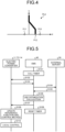
- FIG. 4 is a diagram illustrating an example of an electric power conversion characteristic.
- FIG. 4 is a diagram illustrating a V-P characteristic that is a relation between electric power (P) and voltage (V) on one side of the electric power conversion unit 100a that the electric power converter 14 has, the one side being closer to the bus 30, and FIG. 4 illustrates the electric power conversion characteristic of the electric power conversion unit 100a that the electric power converter 14 has.
- P is a positive value in a state where the electric power conversion unit 100a is supplying electric power to the bus 30, that is, in a state where the electric power conversion unit 100a is converting alternating-current power from the electric power element 24 that is a commercial electric power system into direct-current power, supplying the direct-current power to the bus 30, and using electric power from the commercial electric power system, and P is a negative value in a state where electric power is being supplied from the bus 30, that is, in a reverse power flow state.
- a line DLa illustrated in FIG. 4 is a straight line bent in the middle or a curved line.
- a reference function represented by this line DLa includes connected lines representing three droop functions defined according to intervals of input values, the three droop functions having drooping characteristics different from one another, and the line DLa is determined by the reference function information.
- the reference function information includes, for example, coordinate information on boundaries of the droop functions at coordinates having P along the horizontal axis and V along the vertical axis, intercept information on the droop functions, information on slopes (that is, droop coefficients), and information on forms (straight lines or a curved line, for example).
- the control unit 100c in the electric power converter 14 performs control such that the electric power conversion characteristic of the electric power conversion unit 100a follows the characteristic of the reference function represented by the line DLa. That is, the control unit 100c in the electric power converter 14 controls the electric power conversion unit 100a such that an operating point defined by a value of V and a value of P is positioned on the line DLa.
- the electric power converters 11 to 13 also store reference function information including connected lines representing droop functions correspondingly to the electric power elements connected thereto and control their electric power conversion units 100a such that operating points are positioned on the lines represented by the reference function information.
- a method of controlling the electric power converters 11, 12, 13, and 14 and a method of controlling the electric power system 1 will be described next. What may be executed in the electric power system 1 are: so-called local control where the electric power converters 11, 12, 13, and 14 individually perform autonomous decentralized control; and centralized control where the EMS 40 performs coordinated control of the electric power converters 11, 12, 13, and 14 according to the electric power conditions of the electric power system 1. For example, local control is repeatedly executed on a comparatively short cycle, and the centralized control is executed at longer intervals than those of the cycle of the local control.
- the local control is also called primary control and the centralized control is also called secondary control. Programs cause a processor to execute these control methods, for example, at the electric power converters or the EMS 40.
- a method of controlling the electric power converters 11, 12, 13, and 14 in the local control will be described with respect to the electric power converter 14 serving as an example.
- a control method similar to that described hereinafter may be executed as appropriate at any of the other electric power converters 11 to 13.
- the electric power element 22 is an element that does not control the amount of electric power generated in terms of efficiency, for example, like a photovoltaic device
- control by the maximum power point tracking (MPPT) scheme may be executed, the control being where the electric power converter 12 is caused to operate such that in response to input of electric power corresponding to the amount of electric power from the electric power element 22 and generated by the electric power element 22, output electric power to the bus 30 is maximized with that amount of electric power generated.
- MPPT maximum power point tracking
- the control unit 100c executes a control step of controlling the electric power conversion characteristic of the electric power converter 14, that is, the electric power conversion characteristic of the electric power conversion unit 100a, on the basis of the reference function. Specifically, at the control unit 100c, the operation quantity setting unit 100ca obtains a measured value from the sensor 100b. Subsequently, at the control unit 100c, the operation quantity setting unit 100ca obtains the reference function information from the storage unit 100cd. Subsequently, at the control unit 100c, on the basis of the control method information stored in the storage unit 100cd, the determination unit 100cb determines a feedback control method.
- the operation quantity setting unit 100ca obtains determination information output from the determination unit 100cb, sets, on the basis of the measured value and the reference function information, a quantity of operation for executing feedback control by a control method based on the determination information obtained, and outputs the quantity of operation set, to the electric power conversion unit 100a. Control of the electric power conversion unit 100a is thereby executed.
- the update unit 100cc determines the maximum output of the reference function. For example, in a case where the contracted electric power of the electric power element 24 is electric power P10 illustrated in FIG. 4 and the rated electric power of the alternating-current load 25 is electric power P11 illustrated in FIG. 4 , the update unit 100cc updates the reference function that has been transmitted from the EMS 40 and stored in the storage unit 100cd so that electric power P12 that is the maximum output defined by the reference function becomes "electric power P10 - electric power P11".
- the electric power converter 14 controls the electric power conversion unit 100a such that the operating point is positioned on the line DLa, the maximum electric power output to the bus 30 via the electric power converter 14 from the electric power element 24 is reduced to electric power P12 that is electric power lower than the electric power P12 that is the contracted electric power. Because electric power supplied from the electric power element 24 to the bus 30 then will not exceed the contracted electric power, peak shaving is achieved.
- the electric power converter 14 that is an AC/DC converter does not need to determine reference functions of the electric power converters 11 and 13 for implementing peak shaving, even if the pair of the electric power converter 11 and the electric power element 21 or the pair of the electric power converter 13 and the electric power element 23 is added, the load on the electric power converter 14, which is the AC/DC converter, in the peak shaving is able to be minimized. Furthermore, because the electric power converter 14 does not need to perform communication to and from the electric power converter 11 and the electric power converter 13 for the peak shaving, communication cost is able to be minimized.
- the EMS 40 provided outside the electric power converters 11, 12, 13, and 14 executes the centralized control by updating, through commands, reference functions and feedback control methods used by the electric power converters 11, 12, 13, and 14 in control.
- Updating a reference function and a feedback control method through a command means that the command includes reference function information related to the reference function and control method information related to the feedback control method, and updating, by means of the command, part of the reference function or the whole reference function and the feedback control method.
- the storage unit 100cd of each of the electric power converters 11, 12, 13, and 14 stores the reference function information and the control method information in an updatable manner.
- a command signal for updating the reference function includes the reference function information and the control method information.
- the reference function information is, as described already, coordinate information on boundaries of droop functions, intercept information on the droop functions, information on slopes (that is, droop coefficients), and information on forms (straight lines or a curved line, for example).
- the control method information is information representing droop P control or droop V control.
- the command signal transmitted to the electric power converter 14 may include information on the contracted electric power of the electric power element 24, the rated electric power of the alternating-current load 25, and electric energy received by the EMS 40 from the smart meters M1 and M2.
- the reference function information used in the update and the information on the contracted electric power of the electric power element 24, the rated electric power of the alternating-current load 25, and the electric energy received from the smart meters M1 and M2 have been stored in the storage unit 42 of the EMS 40 and are read and used as appropriate by the control unit 41.
- the EMS 40 calls a timer in the EMS 40 to start measuring time (Step S101). Subsequently, the EMS 40 requests each of the electric power converters 11, 12, 13, and 14 for local measurement information (Step S102).
- the local measurement information is an example of information related to the electric power conditions of the electric power system 1, and includes measured values measured by respective sensors in the electric power converters 11, 12, 13, and 14 and measurement times. Subsequently, each of the electric power converters 11, 12, 13, and 14 transmits the local measurement information to the EMS 40 (Step S103).
- the EMS 40 stores their local measurement information into the storage unit 42.
- the EMS 40 requests the external server 50 for various kinds of information having a possibility of influencing use of the electric power system 1, the various kinds of information being an example of the information related to the electric power conditions of the electric power system 1 (Step S104).
- the EMS 40 requests the external server 50 for electric power generation amount and demand prediction information.
- This electric power generation amount and demand prediction information includes prediction information on the amount of electric power generated and prediction information on a demand for electric power in the electric power system 1, and may include, for example, information on the season, current weather, and future weather forecast in or for the region where the electric power system 1 has been installed.
- the electric power generation amount and demand prediction information may include prediction information on the amount of electric power generated and prediction information on a demand for electric power in the other electric power system. Furthermore, in a case where the information on the electric energy measured by the smart meters M1 and M2 is transmitted to the external server 50 instead of the EMS 40, the electric power generation amount and demand prediction information may include the information on the electric energy measured by the smart meters M1 and M2. Furthermore, in a case where the external server 50 stores the information on the contracted electric power of the electric power element 24 and the rated electric power of the alternating-current load 25, the electric power generation amount and demand prediction information may include these pieces of information.
- the external server 50 transmits the electric power generation amount and demand prediction information to the EMS 40 (Step S105).
- the EMS 40 stores the electric power generation amount and demand prediction information into the storage unit 42.
- the control unit 41 of the EMS 40 reads each piece of information that has been transmitted, that is, for example, the information related to the electric power conditions of the electric power system 1, from the storage unit 42, and executes, on the basis of the pieces of information read, use optimization calculation for the electric power system 1 (Step S106).
- the use optimization calculation is executed for application to various conditions. For example, it is assumed that the electric power system 1 is being controlled such that the bus 30 is at an operating point of a predetermined voltage. It is assumed that in this state, the EMS 40 predicts, from the electric power generation amount and demand prediction information, that the region where the electric power element 22, which is a photovoltaic device, has been installed is going to have clear weather and the amount of electric power generated is going to increase, and determines, from the local measurement information obtained from the electric power converter 12 connected to the electric power element 22, that the electric power element 22 can afford to supply electric power.
- the EMS 40 determines that the reference function of the electric power converter 11 connected to the electric power element 21 is to be updated so that the electric power element 21 that is a stationary electric storage device is charged at the operating point. Furthermore, in this case, the EMS 40 determines that the reference function of the electric power converter 14 connected to the electric power element 24 is to be updated simultaneously with the above update so that electric power is not supplied from the electric power element 24 that is a commercial electric power system.
- the EMS 40 sets, on the basis of a result of the use optimization calculation, reference function information and control method information that are suitable for an electric power converter, for which an update is to be made, the electric power converter being one of the electric power converters 11, 12, 13, and 14, and outputs an update command for a reference function (droop functions) and a feedback control method, the update command including the set reference function information and control method information (Step S107).
- a command signal transmitted to the electric power converter 14 includes the information on the electric energy received by the EMS 40 from the smart meters M1 and M2 or the external server 50 and the information on the rated electric power of the alternating-current load 25 and the contracted electric power of the electric power element 24.
- the EMS 40 resets the timer (Step S108).
- the electric power converter obtains a command for an update of the reference function and an update of the feedback control method and performs the updates of the reference function and the feedback control method, the electric power converter being one of the electric power converters 11, 12, 13, and 14 (Step S109).
- the update command includes the information on the electric energy measured by the smart meters M1 and M2, the information on the rated electric power of the alternating-current load 25, and the information on the contracted electric power of the electric power element 24, the electric power converter 14 performs an update of information on electric energy, rated electric power, and contracted electric power that has been stored.
- the electric power converters 11, 12, 13, and 14 each execute local control (Step S110).
- the electric power converter that has obtained the update command performs local control by using the updated reference function and feedback control method, the electric power converter being one of the electric power converters 11, 12, 13, and 14.
- the electric power converter 14 updates the reference function so that the electric power P12 that is the maximum output of the reference function becomes "electric power P10 - electric power P11", as described above.
- Their local control is local control reflecting the electric power conditions of the electric power system 1 and coordinated control of the electric power converters 11, 12, 13, and 14 is thereby achieved.
- a second embodiment of the present invention will be described next.
- An electric power system according to the second embodiment is different from that of the first embodiment in that the electric power converter 14 updates the reference function according to integral electric energy of electric power supplied from the electric power element 24 to the bus 30 and the alternating-current load 25.
- Other components are the same as those of the first embodiment, these components that are the same as those of the first embodiment will be assigned with the same reference signs, description of these components will be omitted, and the following description will be on differences from the first embodiment.
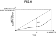
- FIG. 6 is a graph illustrating an example of change in integral electric energy of electric power supplied from the electric power element 24 in 30 minutes.
- a dash-dotted line illustrated in FIG. 6 represents change in integral electric energy in a case where electric power from the electric power element 24 is consumed at constant power consumption such that electric energy supplied by the electric power element 24 equals contracted electric energy of the electric power system 1.
- the update unit 100cc of the electric power converter 14 updates the maximum output defined by the reference function.
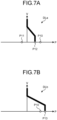
- the electric power converter 14 resets the integral electric energy every time 30 minutes elapse and updates the reference function to a reference function illustrated in FIG. 7A .
- the reference function illustrated in FIG. 7A is a reference function that is the same as the reference function illustrated in FIG. 4 .
- the electric power converter 14 obtains the electric energy consumed by the alternating-current load 25 from the EMS 40 on a predetermined cycle.
- the electric power converter 14 calculates electric energy supplied from the electric power element 24 to the bus 30 on a predetermined cycle, on the basis of a measurement result from the sensor 100b.
- the electric power converter 14 calculates integral electric energy of electric power supplied by the electric power element 24 since the resetting of the integral electric energy and generates a graph representing change in the integral electric energy. Every time the electric power converter 14 calculates integral electric energy, the electric power converter 14 calculates a difference between the latest integral electric energy calculated and the integral electric energy represented by the dash-dotted line at the time point of that calculation, and updates the maximum output defined by the reference function if the difference calculated is equal to or larger than a predetermined threshold.
- FIG. 7B is a diagram illustrating an example of the reference function of the electric power converter 14, the reference function having been updated. For example, if, at a time point t1 in FIG. 6 , the integral electric energy calculated is less than the electric energy indicated by the dash-dotted line and a difference diff1 between the integral electric energy calculated and the integral electric energy indicated by the dash-dotted line is equal to or larger than the predetermined threshold, the electric power converter 14 updates the reference function to a line DLb having the maximum output at electric power P13 exceeding the electric power P10 that is the contracted electric power, as illustrated in FIG. 7B .
- the electric power supplied to the bus 30 is able to be increased.
- a third embodiment of the present invention will be described next.
- An electric power system according to the third embodiment is different from that of the first embodiment in that the electric power converter 14 updates the reference function according to integral electric energy of electric power supplied from the electric power element 24 to the bus 30 and the alternating-current load 25.
- Other components are the same as those of the first embodiment, these components that are the same as those of the first embodiment will be assigned with the same reference signs, description of these components will be omitted, and the following description will be on differences from the first embodiment.
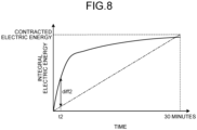
- FIG. 8 is a graph illustrating an example of change in integral electric energy of electric power supplied from the electric power element 24 in 30 minutes.
- a dash-dotted line illustrated in FIG. 8 represents change in integral electric energy in a case where electric power from the electric power element 24 is consumed at constant power consumption such that electric energy supplied by the electric power element 24 equals contracted electric energy of the electric power system 1.
- the update unit 100cc of the electric power converter 14 updates the maximum output defined by the reference function.
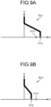
- the electric power converter 14 resets the integral electric energy every time 30 minutes elapse and updates the reference function to a reference function illustrated in FIG. 9A .
- the reference function illustrated in FIG. 9A is a reference function on a line DLc having the maximum output at electric power P14 exceeding the electric power P10 that is the contracted electric power.
- the electric power converter 14 obtains the electric energy consumed by the alternating-current load 25 from the EMS 40 on a predetermined cycle.
- the electric power converter 14 calculates electric energy supplied from the electric power element 24 to the bus 30 on a predetermined cycle on the basis of a measurement result from the sensor 100b.
- the electric power converter 14 calculates integral electric energy of electric power supplied by the electric power element 24 since the resetting of the integral electric energy and generates a graph representing change in the integral electric energy. Every time the electric power converter 14 calculates integral electric energy, the electric power converter 14 calculates a difference between the latest integral electric energy calculated and the integral electric energy represented by the dash-dotted line at the time point of that calculation, and updates the maximum output defined by the reference function if the difference calculated is equal to or larger than a predetermined threshold.
- FIG. 9B is a diagram illustrating an example of the reference function of the electric power converter 14, the reference function having been updated. For example, if, at a time point t2 in FIG. 8 , the calculated integral electric energy is more than the electric energy indicated by the dash-dotted line and a difference diff2 between the calculated integral electric energy and the integral electric energy indicated by the dash-dotted line is equal to or larger than the predetermined threshold, the electric power converter 14 updates the reference function to a line DLd having the maximum output at electric power P15 less than the electric power P10 that is the contracted electric power, as illustrated in FIG. 9B .
- the electric power supplied to the bus 30 is able to be reduced and peak shaving is thereby achieved.
- the reference function at the time the integral electric energy is reset may be the reference function illustrated in FIG. 4 .
- the electric power converter 14 may update the reference function having the maximum output at electric power that is further less than the electric power P12.
- Embodiments of the present invention have been described above, but without being limited to the above described embodiments, the present invention can be implemented in various other modes.
- the above described embodiments may be modified as described below to implement the present invention.
- the above described embodiments and the following modified examples may be combined with one another.
- the present invention also includes those formed by combination of any of the components of the above described embodiments and the following modified examples as appropriate.
- further effects and modified examples can be readily derived by those skilled in the art. Therefore, wider aspects of the present invention are not limited to the above described embodiments and the modified examples, and various modifications can be made.
- the alternating-current load 25 is connected to the electric power element 24, but a configuration having the alternating-current load 25 not connected to the electric power element 24 may be adopted instead.
- the reference function may be set so that the maximum output defined by the reference function becomes electric power less than the electric power P10.
- the reference function may be set so that the maximum output defined by the reference function at the time the integral electric energy is reset becomes electric power less than the electric power P10.
- the integral electric energy is reset every 30 minutes but the integral electric energy may be reset at time intervals other than 30-minute intervals.
- the reference function is updated by use of the rated electric power of the alternating-current load 25, but electric power consumed by the alternating-current load 25 may be measured by the smart meter M2 and the reference function may be updated so that the maximum output of the reference function becomes "electric power P10 - electric power consumed by the alternating-current load 25 and measured by the smart meter M2".
- the reference function is updated so that the electric power P12 that is the maximum output defined by the reference function becomes "electric power P10 - electric power P11", but a method of updating the reference function is not to be limited to this method.
- the reference function of the electric power converter 14 may be updated on the basis of demand prediction information transmitted from the external server 50.
- the EMS 40 obtains demand prediction information on electric power for the alternating-current load 25 from the external server 50 and updates the reference function of the electric power converter 14 on the basis of the demand prediction information obtained.
- the maximum output defined by the reference function may be made equal to electric power less than the electric power P12, and in a case where a demand for electric power at the alternating-current load 25 is predicted to be small, the maximum output defined by the reference function may be made equal to electric power larger than the electric power P12.
- the EMS 40 transmits reference function information representing the updated reference function to the electric power converter 14 and the electric power converter 14 stores the reference function information transmitted, into the storage unit 100cd.
- demand prediction information may be transmitted from the EMS 40 to the electric power converter 14 and the update unit 100cc may perform the update of the reference function based on the demand prediction information instead of the EMS 40.
- the reference function is updated so that that the electric power P12 that is the maximum output defined by the reference functions becomes "electric power P10 - electric power P11", but a method of updating the reference function is not to be limited to this method.
- the electric power converter 14 may update the reference function by using, for example, information on electric energy transmitted from the smart meters M1 and M2, the information being included in a command signal transmitted from the EMS 40.
- the update unit 100cc of the electric power converter 14 predicts electric energy consumed by the alternating-current load 25 from the information on the electric energy transmitted by the smart meter M2. For example, the update unit 100cc generates a graph of change in integral electric energy for the alternating-current load 25 from the information on the electric energy transmitted from the smart meter M2, similarly to the second embodiment or the third embodiment.
- the update unit 100cc extrapolates the graph of the change in the integral electric energy for the alternating-current load 25 at the above described time point t1 or at a time point earlier than the time point t1 to predict the integral electric energy of a time point 30 minutes after resetting of the integral electric energy.
- the update unit 100cc updates the reference function stored in the storage unit 100cd to a reference function defining maximum output larger than the electric power P10.
- the update unit 100cc may update the reference function so that the difference between the maximum output defined and the electric power P10 becomes larger as the difference between the integral electric energy indicated by the dash-dotted line and the predicted integral electric energy becomes larger.
- the update unit 100cc updates the reference function stored in the storage unit 100cd to a reference function defining maximum output less than the electric power P10.
- the update unit 100cc may update the reference function so that the difference between the maximum output defined and the electric power P10 becomes larger as the difference between the integral electric energy indicated by the dash-dotted line and the predicted integral electric energy becomes larger.
- the reference function stored in the storage unit 100cd may be updated to a reference function having the maximum output smaller than the electric power P12. Furthermore, in the above described third embodiment, in a case where the calculated integral electric energy is less than the electric energy indicated by the dash-dotted line in FIG.
- the electric power converter 14 may reset the integral electric energy every time 30 minutes elapse and update the reference function to a reference function having the maximum output at the electric power P10.
- the update unit 100cc may update the reference function stored in the storage unit 100cd to a reference function having the maximum output smaller than the electric power P10, and if the calculated integral electric energy is less than the electric energy indicated by the dash-dotted line in FIG.
- the update unit 100cc may update the reference function stored in the storage unit 100cd to a reference function having the maximum output larger than the electric power P10.
- the present invention can be used for an electric power converter, an electric power system, and a method of controlling the electric power converter.
Landscapes
- Engineering & Computer Science (AREA)
- Power Engineering (AREA)
- Business, Economics & Management (AREA)
- Health & Medical Sciences (AREA)
- Economics (AREA)
- Primary Health Care (AREA)
- Tourism & Hospitality (AREA)
- General Health & Medical Sciences (AREA)
- Human Resources & Organizations (AREA)
- Marketing (AREA)
- Public Health (AREA)
- Strategic Management (AREA)
- Water Supply & Treatment (AREA)
- Physics & Mathematics (AREA)
- General Business, Economics & Management (AREA)
- General Physics & Mathematics (AREA)
- Theoretical Computer Science (AREA)
- Supply And Distribution Of Alternating Current (AREA)
- Remote Monitoring And Control Of Power-Distribution Networks (AREA)
- Inverter Devices (AREA)
- Direct Current Feeding And Distribution (AREA)
Abstract
Description
- The present invention relates to electric power converters, electric power systems, and methods of controlling the electric power converters.
- A system disclosed in
Patent Literature 1, for example, is one of systems that convert alternating-current power from electric power systems into direct-current power to charge storage batteries. This system implements peak shaving by controlling electric power supplied from another storage battery to a storage battery to be charged such that electric power supplied from an AC/DC converter, which converts alternating-current power into direct-current power, to the storage battery to be charged becomes less than a threshold. - Specifically, the AC/DC converter determines drooping characteristics of a DC/DC converter connected to the storage battery to be charged as characteristics, by which the electric current value in the storage battery is increased as the voltage in the bus increases, that is, charging characteristics, and determines drooping characteristics of a DC/DC converter connected to the other storage battery as characteristics, by which the electric current value in the storage battery is decreased as the voltage in the bus increases, that is, discharging characteristics. Each of the DC/DC converters obtains the drooping characteristics determined by the AC/DC converter and controls the electric current in the storage battery according to the drooping characteristics, an electric current corresponding to a shortfall in the discharge from the other storage battery is thereby supplied from the AC/DC converter to the storage battery to be charged, and electric power purchased from an electric power system is thus able to be lessened.
- Patent Literature 1:
Japanese Unexamined Patent Application Publication No. 2021-141761 - Networks that supply electric power include an electric power network (a direct-current grid) having various direct-current devices connected to a direct-current bus via electric power converters that are DC/DC converters, the various direct-current devices being, for example, photovoltaic (PV) devices that are power generation devices to generate electric power using renewable energy, stationary electric storage devices, and electric vehicles (EVs). If the technique disclosed in
Patent Literature 1 is applied to a case where an electric power system has been connected to a direct-current bus via an AC/DC converter, the AC/DC converter will be subjected to a load by having to determine drooping characteristics of DC/DC converters connected to chargeable and dischargeable devices. - The present invention has been made in view of the above and an object thereof is to implement peak shaving with a minimized calculation load.
- To solve the problem described above and to achieve the object, an electric power converter according to one aspect of the present invention includes: an electric power conversion unit configured to convert alternating-current power input from an electric power element, which supplies the alternating-current power, into direct-current power to output the input direct-current power to a direct-current bus; a control unit configured to control the electric power conversion unit to execute control of an output from the electric power conversion unit, based on a reference function having a drooping characteristic defined according to an input value and on either voltage or electric power in a bus to which the electric power conversion unit is connected; and an update unit configured to update the reference function, wherein the update unit is configured to update a maximum output of the electric power conversion unit, based on contracted electric power of the electric power element and on electric power of an alternating-current load that consumes the alternating-current power supplied by the electric power element, the maximum output being defined by the reference function.
- In the electric power converter according to one aspect of the present invention, the update unit may be configured to update the maximum output of the electric power conversion unit, according to integral electric energy of electric power supplied by the electric power element to the electric power conversion unit and the alternating-current load, the maximum output being defined by the reference function.
- In the electric power converter according to one aspect of the present invention, the update unit may be configured to increase the maximum output of the electric power conversion unit when the integral electric energy is less than contracted electric energy of the electric power element, the maximum output being defined by the reference function.
- In the electric power converter according to one aspect of the present invention, the update unit may be configured to decrease the maximum output of the electric power conversion unit when the integral electric energy is more than contracted electric energy of the electric power element, the maximum output being defined by the reference function.
- In the electric power converter according to one aspect of the present invention, the electric power of the alternating-current load may be electric power determined based on a predicted demand at the alternating-current load.
- An electric power system according to one aspect of the present invention includes: the electric power converter; a direct-current bus to which the electric power converter is connected; a direct-current power converter that is connected to the direct-current bus, the direct-current power converter being configured to convert direct-current power input from the direct-current bus to output the converted direct-current power; and an electric power element connected to the direct-current power converter and capable of supplying electric power, consuming electric power, or being charged with electric power.
- A method of controlling an electric power converter according to one aspect of the present invention is a method of controlling an electric power converter including: an electric power conversion unit configured to convert alternating-current power input from an electric power element, which supplies the alternating-current power, into direct-current power to output the input direct-current power to a direct-current bus; a control unit configured to control the electric power conversion unit to execute control of an output from the electric power conversion unit, based on a reference function having a drooping characteristic defined according to an input value and on either voltage or electric power in a bus to which the electric power conversion unit is connected; and an update unit configured to update the reference function, the method including updating a maximum output of the electric power conversion unit, based on contracted electric power of the electric power element and on electric power of an alternating-current load that consumes the alternating-current power supplied by the electric power element, the maximum output being defined by the reference function.
- The present invention enables peak shaving with a minimized calculation load.
-
-
FIG. 1 is a diagram illustrating a configuration of an electric power system according to a first embodiment. -
FIG. 2 is a diagram illustrating a configuration of an electric power converter illustrated inFIG. 1 . -
FIG. 3 is a diagram illustrating a configuration of a control unit illustrated inFIG. 2 . -
FIG. 4 is a diagram illustrating an example of an electric power conversion characteristic. -
FIG. 5 is a sequence diagram illustrating an example of a method of controlling the electric power system. -
FIG. 6 is a diagram illustrating an example of change in integral electric energy of electric power supplied from an electric power element. -
FIG. 7A is a diagram illustrating an example of an electric power conversion characteristic. -
FIG. 7B is a diagram illustrating an example of an electric power conversion characteristic. -
FIG. 8 is a diagram illustrating an example of change in integral electric energy of electric power supplied from an electric power element. -
FIG. 9A is a diagram illustrating an example of an electric power conversion characteristic. -
FIG. 9B is a diagram illustrating an example of an electric power conversion characteristic. - Embodiments of the present invention will be described hereinafter by reference to the drawings. The present invention is not to be limited by the embodiments described hereinafter. Furthermore, the same reference sign is assigned, as appropriate, to any portions that are the same, throughout the drawings.
-
FIG. 1 is a diagram illustrating a configuration of an electric power system according to a first embodiment. Anelectric power system 1 includes:electric power converters electric power elements current load 25; abus 30; and smart meters M1 and M2. Theelectric power system 1 also includes an energy management system (EMS) 40. The EMS 40 is an example of a central control apparatus. - The electric power converters 11 to 13 are DC/DC converters that convert voltage of direct-current power. The
electric power converter 14 is an AC/DC converter that implements conversion between direct-current voltage and alternating-current voltage. Theelectric power converters electric power converters - The
bus 30 is a direct-current bus in theelectric power system 1 and has the electric power converters 11 to 14 connected thereto. An electric power network including a direct-current grid is formed in theelectric power system 1. - The
electric power element 21 is, for example, a stationary electric storage device capable of supplying, consuming, and being charged with electric power, and is connected to the electric power converter 11. The stationary electric storage device is an example of an electric storage device permanently installed in a facility. The electric power converter 11 has a function of converting voltage of direct-current power supplied by theelectric power element 21, outputting the converted voltage to thebus 30, converting voltage of direct-current power supplied from thebus 30, and outputting the converted voltage to theelectric power element 21 to charge theelectric power element 21. The electric power converter 11 is an example of a direct-current power converter. - The
electric power element 22 is, for example, a photovoltaic device capable of generating and supplying electric power and is connected to the electric power converter 12. The photovoltaic device is an example of a power generation device that generates electric power by using renewable energy. The electric power converter 12 has a function of converting voltage of direct-current power supplied by theelectric power element 22 and outputting the converted voltage to thebus 30. - The
electric power element 23 is, for example, an in-vehicle electric storage device capable of supplying, consuming, and being charged with electric power and is connected to theelectric power converter 13. The in-vehicle electric storage device is installed in an electric vehicle EV and is an example of a movable non-stationary electric storage device. Theelectric power converter 13 has a function of converting voltage of direct-current power supplied by theelectric power element 23, outputting the converted voltage to thebus 30, converting voltage of direct-current power supplied from thebus 30, and outputting the converted voltage to theelectric power element 23 to charge theelectric power element 23. Theelectric power converter 13 is provided in, for example, a charging station or a residential charging facility, but may be installed in the electric vehicle EV. Theelectric power converter 13 is an example of a direct-current power converter. - The
electric power element 24 is, for example, a commercial electric power system and is connected to theelectric power converter 14. Theelectric power converter 14 converts alternating-current power supplied by theelectric power element 24 into direct-current power, outputs the direct-current power to thebus 30, converts direct-current power supplied from thebus 30 to alternating-current power, and outputs the alternating-current power to theelectric power element 24. Output of electric power from thebus 30 to theelectric power element 24 is sometimes called a reverse power flow. - The alternating-
current load 25 is a device that operates with alternating-current power and is connected to theelectric power element 24. The alternating-current load 25 is, for example, an electric device or a light fixture in a residence. - The smart meters M1 and M2 are wattmeters having a communication function. The smart meters M1 and M2 have a function of communicating information via a network NW by wire or wirelessly. The smart meter M1 measures electric energy supplied from the
electric power element 24. The smart meter M2 measures electric energy consumed by the alternating-current load 25. The electric energy measured by the smart meters M1 and M2 is transmitted to, for example, the EMS 40 or anexternal server 50. - The EMS 40 has a function of performing integrated management of states of the
electric power system 1. The EMS 40 includes a control unit 41, a storage unit 42, and a communication unit 43. - The control unit 41 performs various kinds of arithmetic processing for implementing the function of the EMS 40, and is configured to include, for example, a processor, such as a central processing unit (CPU), an application specific integrated circuit (ASIC), a fieldprogrammable gate array (FPGA), a digital signal processor (DSP), or a graphics processing unit (GPU). Functions of the control unit 41 are implemented as functional units by the control unit 41 reading and executing various programs from the storage unit 42.
- The storage unit 42 includes, for example, a read only memory (ROM) where various programs and data used by the control unit 41 for the arithmetic processing are stored. Furthermore, the storage unit 42 includes, for example, a random access memory (RAM) used as working space for the arithmetic processing by the control unit 41 and for storage of results of the arithmetic processing by the control unit 41. The storage unit 42 may include an auxiliary storage, such as a hard disk drive (HDD) or a solid state drive (SSD).
- The communication unit 43 includes a communication module that performs communication of information by wire or wirelessly. The communication unit 43 performs communication of information to and from, for example, the electric power converters 11 to 14, the smart meters M1 and M2, and the
external server 50, via the network NW that is, for example, an Internet network or a mobile phone network. - The
external server 50 is a server provided outside the electric power system 100. Theexternal server 50 is, for example, an information processing apparatus configured to function as an EMS in another electric power system, or an information processing apparatus that includes a database and functions as a data server for the EMS 40. Theexternal server 50 stores various kinds of information that possibly have an influence on use of the electric power system 100. - A specific configuration of the
electric power converter 14 will be described next.FIG. 2 is a diagram illustrating a configuration of theelectric power converter 14. Theelectric power converter 14 has an electricpower conversion unit 100a, asensor 100b, acontrol unit 100c, and acommunication unit 100d. - The electric
power conversion unit 100a implements AC/DC conversion of converting alternating-current power supplied from theelectric power element 24 into direct-current power and outputting the direct-current power to thebus 30. Furthermore, the electricpower conversion unit 100a also performs DC/AC conversion of converting direct-current power supplied from thebus 30 into alternating-current power and outputting the alternating-current power to theelectric power element 24. The electricpower conversion unit 100a is formed of an electric circuit including, for example, a coil, a capacitor, a diode, and a switching element. The switching element is, for example, a field-effect capacitor or an insulated gate bipolar transistor. An electric power conversion characteristic of the electricpower conversion unit 100a is able to be controlled by, for example, pulse width modulation (PWM) control. - The
sensor 100b measures an electric characteristic value of electric power on one side of the electricpower conversion unit 100a, the one side being closer to thebus 30. Therefore, thesensor 100b measures an electric characteristic value of electric power input to theelectric power converter 14 or output from theelectric power converter 14. Thesensor 100b is capable of measuring, for example, electric current values, voltage values, and electric power values. Thesensor 100b is an example of a measurement unit that obtains a measured value. Thesensor 100b outputs measured values of electric characteristic values to thecontrol unit 100c. - For implementation mainly of an electric power conversion function of the
electric power converter 14, thecontrol unit 100c is configured to include: a processor that performs various kinds of arithmetic processing for controlling operation of the electricpower conversion unit 100a; and a storage unit. The examples mentioned above as the components of the control unit 41 and the storage unit 42 may be used respectively for the processor and the storage unit. Functions of thecontrol unit 100c are implemented as functional units, by the processor reading and executing various programs from the storage unit. For example, on the basis of a reference function, thecontrol unit 100c controls the electric power conversion characteristic of the electricpower conversion unit 100a. Specifically, thecontrol unit 100c outputs a PWM signal to the electricpower conversion unit 100a to implement PWM control of the electricpower conversion unit 100a, the PWM signal including information on a quantity of operation (for example, a duty ratio) for the PWM control. Thecontrol unit 100c may directly output the quantity of operation to the electricpower conversion unit 100a or may output the quantity of operation to the electricpower conversion unit 100a via another functional unit (for example, a loop control unit) not illustrated in the drawings. -
FIG. 3 is a diagram illustrating a configuration of thecontrol unit 100c, the configuration being related mainly to the electric power conversion function. Thecontrol unit 100c includes an operation quantity setting unit 100ca, a determination unit 100cb, and an update unit 100cc, which are functional units implemented in software by execution of programs, as well as a storage unit 100cd. - The update unit 100cc causes the storage unit 100cd to store reference function information and control method information that are included in an update command input from the
communication unit 100d to update reference function information and control method information that have been stored in the storage unit 100cd. The update unit 100cc also updates the reference function information that has been stored in the storage unit 100cd, on the basis of a measured value supplied from thesensor 100b. The reference function information herein is various kinds of information for determining droop functions composing the reference function and will be described in detail later. Furthermore, the update unit 100cc causes the storage unit 100cd to store contracted electric power of theelectric power element 24 and rated electric power of the alternating-current load 25, which have been transmitted from the EMS 40 and received by thecommunication unit 100d, for example. - The determination unit 100cb makes a determination of a feedback control method to be performed by the operation quantity setting unit 100ca, on the basis of the control method information stored in the storage unit 100cd, and outputs a result of this determination as determination information. This feedback control method may be: feedback control (hereinafter, referred to as droop P control) of determining target electric power Pref (an example of a target value) on the basis of a measured voltage value Vo from the
sensor 100b and the reference function information and setting a quantity of operation so that a difference between Pref and a measured value Po (an example of a control target value) of electric power from thesensor 100b becomes equal to or less than an acceptable range; or feedback control (hereinafter, referred to as droop V control) of determining a target voltage Vref (an example of a target value) on the basis of a measured value Po of electric power from thesensor 100b and the reference function information and setting a quantity of operation so that a difference between the target voltage Vref and a measured voltage value Vo (an example of a control target value) from thesensor 100b becomes equal to or less than an acceptable range. The above described control method information is information representing the droop P control or droop V control, and the determination unit 100cb makes the determination of the feedback control method on the basis of the control method information that has been stored in the storage unit 100cd and outputs, as determination information, the result of the determination to perform the droop P control or the result of the determination to perform the droop V control. - The operation quantity setting unit 100ca sets the feedback control method according to the determination information input from the determination unit 100cb, sets a quantity of operation on the basis of a measured value input from the
sensor 100b and the reference function information obtained from the storage unit 100cd, and outputs the set quantity of operation to the electricpower conversion unit 100a. Feedback control performed by the operation quantity setting unit 100ca may be executed by using a publicly known technique, such as PID control executed by reading parameters, such as proportional gain, integral time, and derivative time that have been stored in the storage unit 100cd, for example. - The storage unit 100cd or the operation quantity setting unit 100ca outputs information, such as information related to electric power conditions and the reference function information, to the
communication unit 100d. - The other electric power converters 11 to 13 may each have a configuration similar to that of the
electric power converter 14. However, the electricpower conversion units 100a of the electric power converters 11 to 13 perform DC/DC conversion of converting voltage of DC electric power input from electric power elements that are being discharged and outputting the converted voltage to thebus 30. Furthermore, the electricpower conversion units 100a of theelectric power converters 11 and 13 are capable of performing DC/DC conversion of voltage of DC power input from thebus 30, outputting the converted voltage, and charging the electric power elements. - The reference function that serves as a basis for the
control unit 100c to control the electric power conversion characteristic of the electricpower conversion unit 100a will be described next.FIG. 4 is a diagram illustrating an example of an electric power conversion characteristic. -
FIG. 4 is a diagram illustrating a V-P characteristic that is a relation between electric power (P) and voltage (V) on one side of the electricpower conversion unit 100a that theelectric power converter 14 has, the one side being closer to thebus 30, andFIG. 4 illustrates the electric power conversion characteristic of the electricpower conversion unit 100a that theelectric power converter 14 has. Herein, P is a positive value in a state where the electricpower conversion unit 100a is supplying electric power to thebus 30, that is, in a state where the electricpower conversion unit 100a is converting alternating-current power from theelectric power element 24 that is a commercial electric power system into direct-current power, supplying the direct-current power to thebus 30, and using electric power from the commercial electric power system, and P is a negative value in a state where electric power is being supplied from thebus 30, that is, in a reverse power flow state. - A line DLa illustrated in
FIG. 4 is a straight line bent in the middle or a curved line. A reference function represented by this line DLa includes connected lines representing three droop functions defined according to intervals of input values, the three droop functions having drooping characteristics different from one another, and the line DLa is determined by the reference function information. - The reference function information includes, for example, coordinate information on boundaries of the droop functions at coordinates having P along the horizontal axis and V along the vertical axis, intercept information on the droop functions, information on slopes (that is, droop coefficients), and information on forms (straight lines or a curved line, for example). The
control unit 100c in theelectric power converter 14 performs control such that the electric power conversion characteristic of the electricpower conversion unit 100a follows the characteristic of the reference function represented by the line DLa. That is, thecontrol unit 100c in theelectric power converter 14 controls the electricpower conversion unit 100a such that an operating point defined by a value of V and a value of P is positioned on the line DLa. - The electric power converters 11 to 13 also store reference function information including connected lines representing droop functions correspondingly to the electric power elements connected thereto and control their electric
power conversion units 100a such that operating points are positioned on the lines represented by the reference function information. - A method of controlling the
electric power converters electric power system 1 will be described next. What may be executed in theelectric power system 1 are: so-called local control where theelectric power converters electric power converters electric power system 1. For example, local control is repeatedly executed on a comparatively short cycle, and the centralized control is executed at longer intervals than those of the cycle of the local control. The local control is also called primary control and the centralized control is also called secondary control. Programs cause a processor to execute these control methods, for example, at the electric power converters or the EMS 40. - A method of controlling the
electric power converters electric power converter 14 serving as an example. A control method similar to that described hereinafter may be executed as appropriate at any of the other electric power converters 11 to 13. In a case where theelectric power element 22 is an element that does not control the amount of electric power generated in terms of efficiency, for example, like a photovoltaic device, control by the maximum power point tracking (MPPT) scheme may be executed, the control being where the electric power converter 12 is caused to operate such that in response to input of electric power corresponding to the amount of electric power from theelectric power element 22 and generated by theelectric power element 22, output electric power to thebus 30 is maximized with that amount of electric power generated. - In the method of controlling the
electric power converter 14, thecontrol unit 100c executes a control step of controlling the electric power conversion characteristic of theelectric power converter 14, that is, the electric power conversion characteristic of the electricpower conversion unit 100a, on the basis of the reference function. Specifically, at thecontrol unit 100c, the operation quantity setting unit 100ca obtains a measured value from thesensor 100b. Subsequently, at thecontrol unit 100c, the operation quantity setting unit 100ca obtains the reference function information from the storage unit 100cd. Subsequently, at thecontrol unit 100c, on the basis of the control method information stored in the storage unit 100cd, the determination unit 100cb determines a feedback control method. Subsequently, at thecontrol unit 100c, the operation quantity setting unit 100ca obtains determination information output from the determination unit 100cb, sets, on the basis of the measured value and the reference function information, a quantity of operation for executing feedback control by a control method based on the determination information obtained, and outputs the quantity of operation set, to the electricpower conversion unit 100a. Control of the electricpower conversion unit 100a is thereby executed. - Peak shaving implemented by the
electric power element 24 will be described next. On the basis of the contracted electric power of theelectric power element 24 and the rated electric power of the alternating-current load 25, which have been received from the EMS 40 and stored in the storage unit 100cd beforehand, the update unit 100cc determines the maximum output of the reference function. For example, in a case where the contracted electric power of theelectric power element 24 is electric power P10 illustrated inFIG. 4 and the rated electric power of the alternating-current load 25 is electric power P11 illustrated inFIG. 4 , the update unit 100cc updates the reference function that has been transmitted from the EMS 40 and stored in the storage unit 100cd so that electric power P12 that is the maximum output defined by the reference function becomes "electric power P10 - electric power P11". - Because the
electric power converter 14 controls the electricpower conversion unit 100a such that the operating point is positioned on the line DLa, the maximum electric power output to thebus 30 via theelectric power converter 14 from theelectric power element 24 is reduced to electric power P12 that is electric power lower than the electric power P12 that is the contracted electric power. Because electric power supplied from theelectric power element 24 to thebus 30 then will not exceed the contracted electric power, peak shaving is achieved. Furthermore, because theelectric power converter 14 that is an AC/DC converter does not need to determine reference functions of theelectric power converters 11 and 13 for implementing peak shaving, even if the pair of the electric power converter 11 and theelectric power element 21 or the pair of theelectric power converter 13 and theelectric power element 23 is added, the load on theelectric power converter 14, which is the AC/DC converter, in the peak shaving is able to be minimized. Furthermore, because theelectric power converter 14 does not need to perform communication to and from the electric power converter 11 and theelectric power converter 13 for the peak shaving, communication cost is able to be minimized. - The centralized control will be described next. In the following example, the EMS 40 provided outside the
electric power converters electric power converters electric power converters - For example, in communication of information between the EMS 40 and the
electric power converter electric power converter 14 may include information on the contracted electric power of theelectric power element 24, the rated electric power of the alternating-current load 25, and electric energy received by the EMS 40 from the smart meters M1 and M2. The reference function information used in the update and the information on the contracted electric power of theelectric power element 24, the rated electric power of the alternating-current load 25, and the electric energy received from the smart meters M1 and M2 have been stored in the storage unit 42 of the EMS 40 and are read and used as appropriate by the control unit 41. - An example of a method of controlling the
electric power system 1, the method being the centralized control, will be described next by reference to a sequence diagram inFIG. 5 . Firstly, the EMS 40 calls a timer in the EMS 40 to start measuring time (Step S101). Subsequently, the EMS 40 requests each of theelectric power converters electric power system 1, and includes measured values measured by respective sensors in theelectric power converters electric power converters - Subsequently, the EMS 40 requests the
external server 50 for various kinds of information having a possibility of influencing use of theelectric power system 1, the various kinds of information being an example of the information related to the electric power conditions of the electric power system 1 (Step S104). In this example, the EMS 40 requests theexternal server 50 for electric power generation amount and demand prediction information. This electric power generation amount and demand prediction information includes prediction information on the amount of electric power generated and prediction information on a demand for electric power in theelectric power system 1, and may include, for example, information on the season, current weather, and future weather forecast in or for the region where theelectric power system 1 has been installed. Furthermore, in a case where theexternal server 50 functions as an EMS of another electric power system, if the use state of that other electric power system has a possibility of influencing the use of theelectric power system 1, the electric power generation amount and demand prediction information may include prediction information on the amount of electric power generated and prediction information on a demand for electric power in the other electric power system. Furthermore, in a case where the information on the electric energy measured by the smart meters M1 and M2 is transmitted to theexternal server 50 instead of the EMS 40, the electric power generation amount and demand prediction information may include the information on the electric energy measured by the smart meters M1 and M2. Furthermore, in a case where theexternal server 50 stores the information on the contracted electric power of theelectric power element 24 and the rated electric power of the alternating-current load 25, the electric power generation amount and demand prediction information may include these pieces of information. - Subsequently, the
external server 50 transmits the electric power generation amount and demand prediction information to the EMS 40 (Step S105). The EMS 40 stores the electric power generation amount and demand prediction information into the storage unit 42. Subsequently, the control unit 41 of the EMS 40 reads each piece of information that has been transmitted, that is, for example, the information related to the electric power conditions of theelectric power system 1, from the storage unit 42, and executes, on the basis of the pieces of information read, use optimization calculation for the electric power system 1 (Step S106). - The use optimization calculation is executed for application to various conditions. For example, it is assumed that the
electric power system 1 is being controlled such that thebus 30 is at an operating point of a predetermined voltage. It is assumed that in this state, the EMS 40 predicts, from the electric power generation amount and demand prediction information, that the region where theelectric power element 22, which is a photovoltaic device, has been installed is going to have clear weather and the amount of electric power generated is going to increase, and determines, from the local measurement information obtained from the electric power converter 12 connected to theelectric power element 22, that theelectric power element 22 can afford to supply electric power. In this case, the EMS 40 determines that the reference function of the electric power converter 11 connected to theelectric power element 21 is to be updated so that theelectric power element 21 that is a stationary electric storage device is charged at the operating point. Furthermore, in this case, the EMS 40 determines that the reference function of theelectric power converter 14 connected to theelectric power element 24 is to be updated simultaneously with the above update so that electric power is not supplied from theelectric power element 24 that is a commercial electric power system. - Subsequently, the EMS 40 sets, on the basis of a result of the use optimization calculation, reference function information and control method information that are suitable for an electric power converter, for which an update is to be made, the electric power converter being one of the
electric power converters electric power converter 14 includes the information on the electric energy received by the EMS 40 from the smart meters M1 and M2 or theexternal server 50 and the information on the rated electric power of the alternating-current load 25 and the contracted electric power of theelectric power element 24. Subsequently, the EMS 40 resets the timer (Step S108). Subsequently, the electric power converter, for which the update is to be made, obtains a command for an update of the reference function and an update of the feedback control method and performs the updates of the reference function and the feedback control method, the electric power converter being one of theelectric power converters 11, 12, 13, and 14 (Step S109). In a case where the update command includes the information on the electric energy measured by the smart meters M1 and M2, the information on the rated electric power of the alternating-current load 25, and the information on the contracted electric power of theelectric power element 24, theelectric power converter 14 performs an update of information on electric energy, rated electric power, and contracted electric power that has been stored. - Subsequently, the
electric power converters electric power converters current load 25 and the contracted electric power of theelectric power element 24, the information being included in the update command, theelectric power converter 14 updates the reference function so that the electric power P12 that is the maximum output of the reference function becomes "electric power P10 - electric power P11", as described above. Their local control is local control reflecting the electric power conditions of theelectric power system 1 and coordinated control of theelectric power converters - A second embodiment of the present invention will be described next. An electric power system according to the second embodiment is different from that of the first embodiment in that the
electric power converter 14 updates the reference function according to integral electric energy of electric power supplied from theelectric power element 24 to thebus 30 and the alternating-current load 25. Other components are the same as those of the first embodiment, these components that are the same as those of the first embodiment will be assigned with the same reference signs, description of these components will be omitted, and the following description will be on differences from the first embodiment. -
FIG. 6 is a graph illustrating an example of change in integral electric energy of electric power supplied from theelectric power element 24 in 30 minutes. A dash-dotted line illustrated inFIG. 6 represents change in integral electric energy in a case where electric power from theelectric power element 24 is consumed at constant power consumption such that electric energy supplied by theelectric power element 24 equals contracted electric energy of theelectric power system 1. - As illustrated in
FIG. 6 , in a case where the total integral electric energy for thebus 30 and the alternating-current load 25 is less than that upon the consumption of the electric power from theelectric power element 24 at the constant power consumption such that the electric energy supplied by theelectric power element 24 equals the contracted electric energy, the update unit 100cc of theelectric power converter 14 updates the maximum output defined by the reference function. - Specifically, the
electric power converter 14 resets the integral electric energy everytime 30 minutes elapse and updates the reference function to a reference function illustrated inFIG. 7A . The reference function illustrated inFIG. 7A is a reference function that is the same as the reference function illustrated inFIG. 4 . Subsequently, theelectric power converter 14 obtains the electric energy consumed by the alternating-current load 25 from the EMS 40 on a predetermined cycle. Furthermore, theelectric power converter 14 calculates electric energy supplied from theelectric power element 24 to thebus 30 on a predetermined cycle, on the basis of a measurement result from thesensor 100b. Subsequently, on the basis of electric energy consumed by the alternating-current load 25 and obtained since resetting of the integral electric energy and the electric energy supplied from theelectric power element 24 to thebus 30 and obtained by calculation, theelectric power converter 14 calculates integral electric energy of electric power supplied by theelectric power element 24 since the resetting of the integral electric energy and generates a graph representing change in the integral electric energy. Every time theelectric power converter 14 calculates integral electric energy, theelectric power converter 14 calculates a difference between the latest integral electric energy calculated and the integral electric energy represented by the dash-dotted line at the time point of that calculation, and updates the maximum output defined by the reference function if the difference calculated is equal to or larger than a predetermined threshold. -
FIG. 7B is a diagram illustrating an example of the reference function of theelectric power converter 14, the reference function having been updated. For example, if, at a time point t1 inFIG. 6 , the integral electric energy calculated is less than the electric energy indicated by the dash-dotted line and a difference diff1 between the integral electric energy calculated and the integral electric energy indicated by the dash-dotted line is equal to or larger than the predetermined threshold, theelectric power converter 14 updates the reference function to a line DLb having the maximum output at electric power P13 exceeding the electric power P10 that is the contracted electric power, as illustrated inFIG. 7B . - According to this embodiment, in a case where an electric power element connected to the alternating-
current load 25 and thebus 30 is using electric power without reaching the contracted electric energy, that is, in a case where there is electric power to spare in electric power used and supplied from theelectric power element 24, the electric power supplied to thebus 30 is able to be increased. - A third embodiment of the present invention will be described next. An electric power system according to the third embodiment is different from that of the first embodiment in that the
electric power converter 14 updates the reference function according to integral electric energy of electric power supplied from theelectric power element 24 to thebus 30 and the alternating-current load 25. Other components are the same as those of the first embodiment, these components that are the same as those of the first embodiment will be assigned with the same reference signs, description of these components will be omitted, and the following description will be on differences from the first embodiment. -
FIG. 8 is a graph illustrating an example of change in integral electric energy of electric power supplied from theelectric power element 24 in 30 minutes. A dash-dotted line illustrated inFIG. 8 represents change in integral electric energy in a case where electric power from theelectric power element 24 is consumed at constant power consumption such that electric energy supplied by theelectric power element 24 equals contracted electric energy of theelectric power system 1. - As illustrated in
FIG. 8 , in a case where the total integral electric energy for thebus 30 and the alternating-current load 25 is more than that upon the consumption of the electric power from theelectric power element 24 at the constant power consumption such that the electric energy supplied by theelectric power element 24 equals the contracted electric energy, the update unit 100cc of theelectric power converter 14 updates the maximum output defined by the reference function. - Specifically, the
electric power converter 14 resets the integral electric energy everytime 30 minutes elapse and updates the reference function to a reference function illustrated inFIG. 9A . The reference function illustrated inFIG. 9A is a reference function on a line DLc having the maximum output at electric power P14 exceeding the electric power P10 that is the contracted electric power. Subsequently, theelectric power converter 14 obtains the electric energy consumed by the alternating-current load 25 from the EMS 40 on a predetermined cycle. Furthermore, theelectric power converter 14 calculates electric energy supplied from theelectric power element 24 to thebus 30 on a predetermined cycle on the basis of a measurement result from thesensor 100b. Subsequently, on the basis of electric energy consumed by the alternating-current load 25 and obtained since resetting of the integral electric energy and the electric energy supplied from theelectric power element 24 to thebus 30 and obtained by calculation, theelectric power converter 14 calculates integral electric energy of electric power supplied by theelectric power element 24 since the resetting of the integral electric energy and generates a graph representing change in the integral electric energy. Every time theelectric power converter 14 calculates integral electric energy, theelectric power converter 14 calculates a difference between the latest integral electric energy calculated and the integral electric energy represented by the dash-dotted line at the time point of that calculation, and updates the maximum output defined by the reference function if the difference calculated is equal to or larger than a predetermined threshold. -
FIG. 9B is a diagram illustrating an example of the reference function of theelectric power converter 14, the reference function having been updated. For example, if, at a time point t2 inFIG. 8 , the calculated integral electric energy is more than the electric energy indicated by the dash-dotted line and a difference diff2 between the calculated integral electric energy and the integral electric energy indicated by the dash-dotted line is equal to or larger than the predetermined threshold, theelectric power converter 14 updates the reference function to a line DLd having the maximum output at electric power P15 less than the electric power P10 that is the contracted electric power, as illustrated inFIG. 9B . - According to this embodiment, in a case where an electric power element connected to the alternating-
current load 25 and thebus 30 is using electric power so that the contracted electric energy is exceeded, that is, in a case where there is no electric power to spare in electric power used and supplied from theelectric power element 24, the electric power supplied to thebus 30 is able to be reduced and peak shaving is thereby achieved. - In this third embodiment, the reference function at the time the integral electric energy is reset may be the reference function illustrated in
FIG. 4 . In a case where the integral electric energy is more than the electric energy indicated by the dash-dotted line and the difference diff2 between the integral electric energy and the integral electric energy indicated by the dash-dotted line is equal to or larger than the predetermined threshold when the reference function is the reference function illustrated inFIG. 4 , theelectric power converter 14 may update the reference function having the maximum output at electric power that is further less than the electric power P12. - Embodiments of the present invention have been described above, but without being limited to the above described embodiments, the present invention can be implemented in various other modes. For example, the above described embodiments may be modified as described below to implement the present invention. The above described embodiments and the following modified examples may be combined with one another. The present invention also includes those formed by combination of any of the components of the above described embodiments and the following modified examples as appropriate. Furthermore, further effects and modified examples can be readily derived by those skilled in the art. Therefore, wider aspects of the present invention are not limited to the above described embodiments and the modified examples, and various modifications can be made.
- In the above described embodiments, the alternating-
current load 25 is connected to theelectric power element 24, but a configuration having the alternating-current load 25 not connected to theelectric power element 24 may be adopted instead. In this case, in theelectric power converter 14 according to the first embodiment, even if the alternating-current load 25 is not connected to theelectric power element 24, the reference function may be set so that the maximum output defined by the reference function becomes electric power less than the electric power P10. Furthermore, in the case where the alternating-current load 25 is not connected to theelectric power element 24, in theelectric power converter 14 according to the second embodiment also, the reference function may be set so that the maximum output defined by the reference function at the time the integral electric energy is reset becomes electric power less than the electric power P10. - In the above described second embodiment and third embodiment, the integral electric energy is reset every 30 minutes but the integral electric energy may be reset at time intervals other than 30-minute intervals.
- In the above described embodiments, the reference function is updated by use of the rated electric power of the alternating-
current load 25, but electric power consumed by the alternating-current load 25 may be measured by the smart meter M2 and the reference function may be updated so that the maximum output of the reference function becomes "electric power P10 - electric power consumed by the alternating-current load 25 and measured by the smart meter M2". - In the above described first embodiment, the reference function is updated so that the electric power P12 that is the maximum output defined by the reference function becomes "electric power P10 - electric power P11", but a method of updating the reference function is not to be limited to this method. According to the present invention, the reference function of the
electric power converter 14 may be updated on the basis of demand prediction information transmitted from theexternal server 50. In this case, the EMS 40 obtains demand prediction information on electric power for the alternating-current load 25 from theexternal server 50 and updates the reference function of theelectric power converter 14 on the basis of the demand prediction information obtained. For example, in a case where a demand for electric power at the alternating-current load 25 is predicted to be large, the maximum output defined by the reference function may be made equal to electric power less than the electric power P12, and in a case where a demand for electric power at the alternating-current load 25 is predicted to be small, the maximum output defined by the reference function may be made equal to electric power larger than the electric power P12. The EMS 40 transmits reference function information representing the updated reference function to theelectric power converter 14 and theelectric power converter 14 stores the reference function information transmitted, into the storage unit 100cd. Furthermore, according to the present invention, demand prediction information may be transmitted from the EMS 40 to theelectric power converter 14 and the update unit 100cc may perform the update of the reference function based on the demand prediction information instead of the EMS 40. - In the above described first embodiment, the reference function is updated so that that the electric power P12 that is the maximum output defined by the reference functions becomes "electric power P10 - electric power P11", but a method of updating the reference function is not to be limited to this method. The
electric power converter 14 may update the reference function by using, for example, information on electric energy transmitted from the smart meters M1 and M2, the information being included in a command signal transmitted from the EMS 40. - Specifically, the update unit 100cc of the
electric power converter 14 predicts electric energy consumed by the alternating-current load 25 from the information on the electric energy transmitted by the smart meter M2. For example, the update unit 100cc generates a graph of change in integral electric energy for the alternating-current load 25 from the information on the electric energy transmitted from the smart meter M2, similarly to the second embodiment or the third embodiment. The update unit 100cc extrapolates the graph of the change in the integral electric energy for the alternating-current load 25 at the above described time point t1 or at a time point earlier than the time point t1 to predict the integral electric energy of atime point 30 minutes after resetting of the integral electric energy. - In a case where the predicted integral electric energy for the
time point 30 minutes later is less than the integral electric energy indicated by the dash-dotted line inFIG. 6 orFIG. 8 , the update unit 100cc updates the reference function stored in the storage unit 100cd to a reference function defining maximum output larger than the electric power P10. In this case, the update unit 100cc may update the reference function so that the difference between the maximum output defined and the electric power P10 becomes larger as the difference between the integral electric energy indicated by the dash-dotted line and the predicted integral electric energy becomes larger. - Furthermore, in a case where the predicted integral electric energy for the
time point 30 minutes later is more than the integral electric energy indicated by the dash-dotted line inFIG. 6 orFIG. 8 , the update unit 100cc updates the reference function stored in the storage unit 100cd to a reference function defining maximum output less than the electric power P10. In this case, the update unit 100cc may update the reference function so that the difference between the maximum output defined and the electric power P10 becomes larger as the difference between the integral electric energy indicated by the dash-dotted line and the predicted integral electric energy becomes larger. - In the above described second embodiment, in a case where the calculated integral electric energy is more than the electric energy indicated by the dash-dotted line in
FIG. 6 and the difference between the calculated integral electric energy and the integral electric energy indicated by the dash-dotted line is equal to larger than the predetermined threshold, the reference function stored in the storage unit 100cd may be updated to a reference function having the maximum output smaller than the electric power P12. Furthermore, in the above described third embodiment, in a case where the calculated integral electric energy is less than the electric energy indicated by the dash-dotted line inFIG. 8 and the difference between the calculated integral electric energy and the integral electric energy indicated by the dash-dotted line is equal to larger than the predetermined threshold, the reference function stored in the storage unit 100cd may be updated to a reference function having the maximum output larger than the electric power P14. - Furthermore, according to the present invention, the
electric power converter 14 may reset the integral electric energy everytime 30 minutes elapse and update the reference function to a reference function having the maximum output at the electric power P10. In this case, if the calculated integral electric energy is more than the electric energy indicated by the dash-dotted line inFIG. 6 and a difference between the calculated integral electric energy and the integral electric energy indicated by the dash-dotted line is equal to or larger than the predetermined threshold, the update unit 100cc may update the reference function stored in the storage unit 100cd to a reference function having the maximum output smaller than the electric power P10, and if the calculated integral electric energy is less than the electric energy indicated by the dash-dotted line inFIG. 6 and the difference between the calculated integral electric energy and the integral electric energy indicated by the dash-dotted line is equal to or larger than the predetermined threshold, the update unit 100cc may update the reference function stored in the storage unit 100cd to a reference function having the maximum output larger than the electric power P10. - The present invention can be used for an electric power converter, an electric power system, and a method of controlling the electric power converter.
-
- 1 ELECTRIC POWER SYSTEM
- 11, 12, 13, 14 ELECTRIC POWER CONVERTER
- 21, 22, 23, 24 ELECTRIC POWER ELEMENT
- 25 ALTERNATING-CURRENT LOAD
- 30 BUS
- 40 EMS
- 100a ELECTRIC POWER CONVERSION UNIT
- 100b SENSOR
- 100c, 41 CONTROL UNIT
- 100ca OPERATION QUANTITY SETTING UNIT
- 100cb DETERMINATION UNIT
- 100cc UPDATE UNIT
- 100cd, 42 STORAGE UNIT
- 100d, 43 COMMUNICATION UNIT
- DLa, DLb, DLc, DLd LINE
- EV ELECTRIC VEHICLE
- M1, M2 SMART METER
- NW NETWORK
Claims (7)
- An electric power converter, comprising:an electric power conversion unit configured to convert alternating-current power input from an electric power element, which supplies the alternating-current power, into direct-current power to output the input direct-current power to a direct-current bus;a control unit configured to control the electric power conversion unit to execute control of an output from the electric power conversion unit, based on a reference function having a drooping characteristic defined according to an input value and on either voltage or electric power in a bus to which the electric power conversion unit is connected; andan update unit configured to update the reference function, whereinthe update unit is configured to update a maximum output of the electric power conversion unit, based on contracted electric power of the electric power element and on electric power of an alternating-current load that consumes the alternating-current power supplied by the electric power element, the maximum output being defined by the reference function.
- The electric power converter according to claim 1, wherein the update unit is configured to update the maximum output of the electric power conversion unit, according to integral electric energy of electric power supplied by the electric power element to the electric power conversion unit and the alternating-current load, the maximum output being defined by the reference function.
- The electric power converter according to claim 2, wherein the update unit is configured to increase the maximum output of the electric power conversion unit when the integral electric energy is less than contracted electric energy of the electric power element, the maximum output being defined by the reference function.
- The electric power converter according to claim 2 or claim 3, wherein the update unit is configured to decrease the maximum output of the electric power conversion unit when the integral electric energy is more than contracted electric energy of the electric power element, the maximum output being defined by the reference function.
- The electric power converter according to claim 1, wherein the electric power of the alternating-current load is electric power determined based on a predicted demand at the alternating-current load.
- An electric power system, comprising:the electric power converter according to any one of claims 1 to 5;a direct-current bus to which the electric power converter is connected;a direct-current power converter that is connected to the direct-current bus, the direct-current power converter being configured to convert direct-current power input from the direct-current bus to output the converted direct-current power; andan electric power element connected to the direct-current power converter and capable of supplying electric power, consuming electric power, or being charged with electric power.
- A method of controlling an electric power converter comprising: an electric power conversion unit configured to convert alternating-current power input from an electric power element, which supplies the alternating-current power, into direct-current power to output the input direct-current power to a direct-current bus; a control unit configured to control the electric power conversion unit to execute control of an output from the electric power conversion unit, based on a reference function having a drooping characteristic defined according to an input value and on either voltage or electric power in a bus to which the electric power conversion unit is connected; and an update unit configured to update the reference function, the method comprising
updating a maximum output of the electric power conversion unit, based on contracted electric power of the electric power element and on electric power of an alternating-current load that consumes the alternating-current power supplied by the electric power element, the maximum output being defined by the reference function.
Applications Claiming Priority (2)
| Application Number | Priority Date | Filing Date | Title |
|---|---|---|---|
| JP2022026155 | 2022-02-22 | ||
| PCT/JP2022/032872 WO2023162298A1 (en) | 2022-02-22 | 2022-08-31 | Power converter, power system, and control method for power converter |
Publications (2)
| Publication Number | Publication Date |
|---|---|
| EP4485734A1 true EP4485734A1 (en) | 2025-01-01 |
| EP4485734A4 EP4485734A4 (en) | 2026-04-22 |
Family
ID=87765347
Family Applications (1)
| Application Number | Title | Priority Date | Filing Date |
|---|---|---|---|
| EP22928819.6A Pending EP4485734A4 (en) | 2022-02-22 | 2022-08-31 | POWER CONVERTER, POWER SUPPLY SYSTEM AND CONTROL METHOD FOR A POWER CONVERTER |
Country Status (6)
| Country | Link |
|---|---|
| US (1) | US20240413736A1 (en) |
| EP (1) | EP4485734A4 (en) |
| JP (1) | JP7547684B2 (en) |
| KR (1) | KR20240151164A (en) |
| CN (1) | CN118715691A (en) |
| WO (1) | WO2023162298A1 (en) |
Families Citing this family (1)
| Publication number | Priority date | Publication date | Assignee | Title |
|---|---|---|---|---|
| CN120322931A (en) * | 2022-12-06 | 2025-07-15 | 古河电气工业株式会社 | Power converter, power system, control method and program for power converter |
Family Cites Families (9)
| Publication number | Priority date | Publication date | Assignee | Title |
|---|---|---|---|---|
| JP2005065480A (en) * | 2003-07-29 | 2005-03-10 | Shin Kobe Electric Mach Co Ltd | Charging method of power storage system |
| WO2012000549A1 (en) * | 2010-06-30 | 2012-01-05 | Abb Research Ltd | Method and control device for controlling power flow within a dc power transmission network |
| US10720771B2 (en) * | 2016-05-18 | 2020-07-21 | Mitsubishi Electric Corporation | Current/voltage control apparatus |
| JP2017212785A (en) | 2016-05-24 | 2017-11-30 | 株式会社東芝 | Converter system and control method thereof |
| IT201600131878A1 (en) * | 2016-12-28 | 2018-06-28 | Electro Power Systems Mfg S R L | MICRORETAL CONTROL SYSTEM FOR THE PRODUCTION AND DISTRIBUTION OF ELECTRIC ENERGY FROM DIFFERENT SOURCES OF PRODUCTION, AND ITS CONTROL METHOD |
| JP7165876B2 (en) | 2018-06-12 | 2022-11-07 | パナソニックIpマネジメント株式会社 | control system |
| US11456602B2 (en) * | 2019-04-25 | 2022-09-27 | King Fahd University Of Petroleum And Minerals | Method for stabilizing an autonomous microgrid including an active load |
| JP2021141761A (en) | 2020-03-06 | 2021-09-16 | パナソニックIpマネジメント株式会社 | Charge/discharge system, charge/discharge method, and program |
| WO2022004611A1 (en) * | 2020-06-30 | 2022-01-06 | 古河電気工業株式会社 | Power converter, control method for power converter, power system, control method for power system, and program |
-
2022
- 2022-08-31 JP JP2024502799A patent/JP7547684B2/en active Active
- 2022-08-31 EP EP22928819.6A patent/EP4485734A4/en active Pending
- 2022-08-31 WO PCT/JP2022/032872 patent/WO2023162298A1/en not_active Ceased
- 2022-08-31 KR KR1020247026023A patent/KR20240151164A/en active Pending
- 2022-08-31 CN CN202280091985.6A patent/CN118715691A/en active Pending
-
2024
- 2024-08-21 US US18/811,745 patent/US20240413736A1/en active Pending
Also Published As
| Publication number | Publication date |
|---|---|
| JP7547684B2 (en) | 2024-09-09 |
| WO2023162298A1 (en) | 2023-08-31 |
| JPWO2023162298A1 (en) | 2023-08-31 |
| EP4485734A4 (en) | 2026-04-22 |
| US20240413736A1 (en) | 2024-12-12 |
| CN118715691A (en) | 2024-09-27 |
| KR20240151164A (en) | 2024-10-17 |
Similar Documents
| Publication | Publication Date | Title |
|---|---|---|
| US12494702B2 (en) | Electric power converter, method of controlling electric power converter, and computer readable recording medium | |
| US20230327434A1 (en) | Power converter and control method of power converter | |
| US20230114812A1 (en) | Electric power converter, control method for electric power converter, electric power system, control method for electric power system, and computer readable recording medium | |
| US20240413736A1 (en) | Electric power converter, electric power system, and method of controlling electric power converter | |
| JP7688030B2 (en) | Power converter, power converter control method, power system, power system control method and program | |
| US12483037B2 (en) | Power converter, power system, and control method of power converter | |
| JP7727513B2 (en) | Power converter, power system, and power converter control method | |
| JP7672426B2 (en) | Power system and method for controlling power system | |
| EP4456401A1 (en) | Power converter, power system, and method for controlling power converter | |
| JP2023140776A (en) | Power converter, power system and power converter control method | |
| JP7693960B2 (en) | Power system, control device and control method | |
| US20250149965A1 (en) | Power control device, power system, control method of power control device, and control method of central control device |
Legal Events
| Date | Code | Title | Description |
|---|---|---|---|
| STAA | Information on the status of an ep patent application or granted ep patent |
Free format text: STATUS: THE INTERNATIONAL PUBLICATION HAS BEEN MADE |
|
| PUAI | Public reference made under article 153(3) epc to a published international application that has entered the european phase |
Free format text: ORIGINAL CODE: 0009012 |
|
| STAA | Information on the status of an ep patent application or granted ep patent |
Free format text: STATUS: REQUEST FOR EXAMINATION WAS MADE |
|
| 17P | Request for examination filed |
Effective date: 20240806 |
|
| AK | Designated contracting states |
Kind code of ref document: A1 Designated state(s): AL AT BE BG CH CY CZ DE DK EE ES FI FR GB GR HR HU IE IS IT LI LT LU LV MC MK MT NL NO PL PT RO RS SE SI SK SM TR |
|
| DAV | Request for validation of the european patent (deleted) | ||
| DAX | Request for extension of the european patent (deleted) | ||
| REG | Reference to a national code |
Ref country code: DE Ref legal event code: R079 Free format text: PREVIOUS MAIN CLASS: H02J0003140000 Ipc: H02J0001102000 |
|
| A4 | Supplementary search report drawn up and despatched |
Effective date: 20260324 |
|
| RIC1 | Information provided on ipc code assigned before grant |
Ipc: H02J 1/102 20260101AFI20260318BHEP Ipc: H02J 3/32 20060101ALI20260318BHEP |