EP4485709A1 - High-voltage connector capable of realizing jogging control over high-voltage inter-lock - Google Patents
High-voltage connector capable of realizing jogging control over high-voltage inter-lock Download PDFInfo
- Publication number
- EP4485709A1 EP4485709A1 EP23759089.8A EP23759089A EP4485709A1 EP 4485709 A1 EP4485709 A1 EP 4485709A1 EP 23759089 A EP23759089 A EP 23759089A EP 4485709 A1 EP4485709 A1 EP 4485709A1
- Authority
- EP
- European Patent Office
- Prior art keywords
- voltage
- lock
- inter
- voltage inter
- jogging control
- Prior art date
- Legal status (The legal status is an assumption and is not a legal conclusion. Google has not performed a legal analysis and makes no representation as to the accuracy of the status listed.)
- Granted
Links
Images




Classifications
-
- H—ELECTRICITY
- H01—ELECTRIC ELEMENTS
- H01R—ELECTRICALLY-CONDUCTIVE CONNECTIONS; STRUCTURAL ASSOCIATIONS OF A PLURALITY OF MUTUALLY-INSULATED ELECTRICAL CONNECTING ELEMENTS; COUPLING DEVICES; CURRENT COLLECTORS
- H01R13/00—Details of coupling devices of the kinds covered by groups H01R12/70 or H01R24/00 - H01R33/00
- H01R13/62—Means for facilitating engagement or disengagement of coupling parts or for holding them in engagement
- H01R13/639—Additional means for holding or locking coupling parts together, after engagement, e.g. separate keylock, retainer strap
-
- H—ELECTRICITY
- H01—ELECTRIC ELEMENTS
- H01R—ELECTRICALLY-CONDUCTIVE CONNECTIONS; STRUCTURAL ASSOCIATIONS OF A PLURALITY OF MUTUALLY-INSULATED ELECTRICAL CONNECTING ELEMENTS; COUPLING DEVICES; CURRENT COLLECTORS
- H01R13/00—Details of coupling devices of the kinds covered by groups H01R12/70 or H01R24/00 - H01R33/00
- H01R13/46—Bases; Cases
- H01R13/53—Bases or cases for heavy duty; Bases or cases for high voltage with means for preventing corona or arcing
-
- H—ELECTRICITY
- H01—ELECTRIC ELEMENTS
- H01R—ELECTRICALLY-CONDUCTIVE CONNECTIONS; STRUCTURAL ASSOCIATIONS OF A PLURALITY OF MUTUALLY-INSULATED ELECTRICAL CONNECTING ELEMENTS; COUPLING DEVICES; CURRENT COLLECTORS
- H01R13/00—Details of coupling devices of the kinds covered by groups H01R12/70 or H01R24/00 - H01R33/00
- H01R13/62—Means for facilitating engagement or disengagement of coupling parts or for holding them in engagement
- H01R13/627—Snap or like fastening
-
- H—ELECTRICITY
- H01—ELECTRIC ELEMENTS
- H01R—ELECTRICALLY-CONDUCTIVE CONNECTIONS; STRUCTURAL ASSOCIATIONS OF A PLURALITY OF MUTUALLY-INSULATED ELECTRICAL CONNECTING ELEMENTS; COUPLING DEVICES; CURRENT COLLECTORS
- H01R13/00—Details of coupling devices of the kinds covered by groups H01R12/70 or H01R24/00 - H01R33/00
- H01R13/66—Structural association with built-in electrical component
- H01R13/70—Structural association with built-in electrical component with built-in switch
-
- H—ELECTRICITY
- H01—ELECTRIC ELEMENTS
- H01R—ELECTRICALLY-CONDUCTIVE CONNECTIONS; STRUCTURAL ASSOCIATIONS OF A PLURALITY OF MUTUALLY-INSULATED ELECTRICAL CONNECTING ELEMENTS; COUPLING DEVICES; CURRENT COLLECTORS
- H01R13/00—Details of coupling devices of the kinds covered by groups H01R12/70 or H01R24/00 - H01R33/00
- H01R13/66—Structural association with built-in electrical component
- H01R13/70—Structural association with built-in electrical component with built-in switch
- H01R13/703—Structural association with built-in electrical component with built-in switch operated by engagement or disengagement of coupling parts, e.g. dual-continuity coupling part
- H01R13/7031—Shorting, shunting or bussing of different terminals interrupted or effected on engagement of coupling part, e.g. for ESD protection, line continuity
- H01R13/7032—Shorting, shunting or bussing of different terminals interrupted or effected on engagement of coupling part, e.g. for ESD protection, line continuity making use of a separate bridging element directly cooperating with the terminals
-
- H—ELECTRICITY
- H01—ELECTRIC ELEMENTS
- H01R—ELECTRICALLY-CONDUCTIVE CONNECTIONS; STRUCTURAL ASSOCIATIONS OF A PLURALITY OF MUTUALLY-INSULATED ELECTRICAL CONNECTING ELEMENTS; COUPLING DEVICES; CURRENT COLLECTORS
- H01R13/00—Details of coupling devices of the kinds covered by groups H01R12/70 or H01R24/00 - H01R33/00
- H01R13/66—Structural association with built-in electrical component
- H01R13/70—Structural association with built-in electrical component with built-in switch
- H01R13/707—Structural association with built-in electrical component with built-in switch interlocked with contact members or counterpart
-
- H—ELECTRICITY
- H01—ELECTRIC ELEMENTS
- H01R—ELECTRICALLY-CONDUCTIVE CONNECTIONS; STRUCTURAL ASSOCIATIONS OF A PLURALITY OF MUTUALLY-INSULATED ELECTRICAL CONNECTING ELEMENTS; COUPLING DEVICES; CURRENT COLLECTORS
- H01R24/00—Two-part coupling devices, or either of their cooperating parts, characterised by their overall structure
-
- H—ELECTRICITY
- H01—ELECTRIC ELEMENTS
- H01R—ELECTRICALLY-CONDUCTIVE CONNECTIONS; STRUCTURAL ASSOCIATIONS OF A PLURALITY OF MUTUALLY-INSULATED ELECTRICAL CONNECTING ELEMENTS; COUPLING DEVICES; CURRENT COLLECTORS
- H01R13/00—Details of coupling devices of the kinds covered by groups H01R12/70 or H01R24/00 - H01R33/00
- H01R13/62—Means for facilitating engagement or disengagement of coupling parts or for holding them in engagement
- H01R13/629—Additional means for facilitating engagement or disengagement of coupling parts, e.g. aligning or guiding means, levers, gas pressure electrical locking indicators, manufacturing tolerances
- H01R13/62933—Comprising exclusively pivoting lever
-
- H—ELECTRICITY
- H01—ELECTRIC ELEMENTS
- H01R—ELECTRICALLY-CONDUCTIVE CONNECTIONS; STRUCTURAL ASSOCIATIONS OF A PLURALITY OF MUTUALLY-INSULATED ELECTRICAL CONNECTING ELEMENTS; COUPLING DEVICES; CURRENT COLLECTORS
- H01R13/00—Details of coupling devices of the kinds covered by groups H01R12/70 or H01R24/00 - H01R33/00
- H01R13/62—Means for facilitating engagement or disengagement of coupling parts or for holding them in engagement
- H01R13/629—Additional means for facilitating engagement or disengagement of coupling parts, e.g. aligning or guiding means, levers, gas pressure electrical locking indicators, manufacturing tolerances
- H01R13/62933—Comprising exclusively pivoting lever
- H01R13/62938—Pivoting lever comprising own camming means
-
- H—ELECTRICITY
- H01—ELECTRIC ELEMENTS
- H01R—ELECTRICALLY-CONDUCTIVE CONNECTIONS; STRUCTURAL ASSOCIATIONS OF A PLURALITY OF MUTUALLY-INSULATED ELECTRICAL CONNECTING ELEMENTS; COUPLING DEVICES; CURRENT COLLECTORS
- H01R2201/00—Connectors or connections adapted for particular applications
- H01R2201/26—Connectors or connections adapted for particular applications for vehicles
Definitions
- the present disclosure relates to the technical field of high-voltage connectors of new energy vehicles, and particularly to a high-voltage connector for jogging control over high-voltage inter-lock.
- the high-voltage connectors of new energy vehicles include high-voltage inter-lock devices, which are used to confirm the integrity of the entire high-voltage electrical system with a small current of 12V. All high-voltage components and wiring harness connectors of the whole vehicle must be mounted in place without short circuit or open circuit.
- a controller detects that a High Voltage Inter-lock (HVIL) loop is disconnected or the integrity is damaged, it initiates essential safety measures.
- HVIL High Voltage Inter-lock
- BMS Battery Management System selects different essential safety measures according to the vehicle conditions at that time.
- a high-voltage loop is powered on.
- the high-voltage loop is powered off immediately.
- the high-voltage inter-lock can ensure the safety of operators: when the high-voltage connector is to be unplugged, the high-voltage inter-lock loop must be disconnected before the high-voltage loop is disconnected; when the high-voltage connector is to be plugged, the high-voltage inter-lock circuit is connected and conducted after a power terminal is contacted and conducted; otherwise the power terminal will be still in a live state during plugging and unplugging of the high-voltage connector, which is easy to cause arcing and endanger the personal safety of operators.
- the high-voltage inter-lock devices in the prior art for high-voltage connection all use a pin terminal 201 to cooperate with a socket terminal 202 to form a high-voltage inter-lock loop. Since both the pin terminal 201 and the socket terminal 202 have a certain length, when an operator plugs or unplugs the high-voltage connector, he has to plug or unplug for a certain distance to disconnect or connect the inter-lock loop.
- the high-voltage loop is still in a live state, which means that the operator's operation for a period of time is still high-voltage live plugging and unplugging, thus posing a risk to the operator's safety and creating a potential safety hazard.
- the inventor proposes a high-voltage connector for jogging control over high-voltage inter-lock, so as to overcome the defects in the prior art.
- the present disclosure aims to provide a high-voltage connector for jogging control over high-voltage inter-lock, which solves the problems mentioned in the section of Background, realizes a jogging control over high-voltage inter-lock, such that a high-voltage inter-lock system can be switched on and switched off within an extremely short period of time, thereby greatly reducing a distance of live-line plugging and unplugging, and controlling the power-on and power-off of a high-voltage loop within an extremely short period of time.
- a high-voltage connector for jogging control over high-voltage inter-lock including a socket housing and a plug housing.
- the high-voltage connector further includes a high-voltage inter-lock system, on which a jogging control structure is provided.
- the jogging control structure is configured to control, by means of a short-distance action, the high-voltage inter-lock system to be powered on or powered off, so as to control an electrical connectivity state between the high-voltage male terminal and the high-voltage female terminal.
- the high-voltage connector for jogging control over high-voltage inter-lock of the present disclosure achieves the following advantageous effect:
- the high-voltage connector for jogging control over high-voltage inter-lock of the present disclosure is provided with a jogging control structure, which can realize jogging control over high-voltage inter-lock, such that a high-voltage inter-lock system can be switched on and switched off within an extremely short period of time, thereby greatly reducing the reassembly time and the plugging distance, reducing the distance of live-line plugging and unplugging, achieving the jogging control, reducing the potential safety hazards, and ensuring the connection stability of the high-voltage inter-lock system.
- the present disclosure effectively solves the problem of live-line plugging and unplugging of the high-voltage connectors during plugging and unplugging, reduces the potential safety hazards during plugging and unplugging of the high-voltage connector, and ensures the personal safety of operators.
- 100 high-voltage connector for jogging control over high-voltage inter-lock; 1: socket housing; 11: connecting post; 12: positioning block; 13: positioning clamping groove; 14: positioning claw; 2: dual self-locking structure; 3: high-voltage inter-lock terminal; 31: transition signal line; 4: jogging control structure; 41: return spring; 42: high-voltage inter-lock short-distance connection reed; 421: first accommodating curved groove; 422: second accommodating curved groove; 423: connecting tab; 424: reed insertion portion; 43: jogging control slider; 431: guide post; 432: slider body; 433: reed connecting plate; 434: tab clamping groove; 435: reed plugging groove; 44: jogging control housing; 441: guide post through-hole; 442: positioning protrusion; 45: microswitch; 451: switch housing; 452: switch button; 5: high-voltage male terminal; 6: plug
- a connection may be a mechanical connection or an electrical connection, or an internal communication between two elements, or a direct connection, or an indirect connection through an intermediate medium.
- a connection may be a mechanical connection or an electrical connection, or an internal communication between two elements, or a direct connection, or an indirect connection through an intermediate medium.
- the present disclosure provides a high-voltage connector 100 for jogging control over high-voltage inter-lock, including a socket housing 1 and a plug housing 6.
- the high-voltage connector further includes a high-voltage inter-lock system configured to control an electrical connectivity state between the high-voltage male terminal 5 and the high-voltage female terminal 9.
- the high-voltage inter-lock system By plugging the high-voltage male terminal 5 and the high-voltage female terminal 9 with each other and further moving them toward each other for a first distance, the high-voltage inter-lock system is powered on, and then the high-voltage male terminal 5 and the high-voltage female terminal 9 are electrically connected; by moving the high-voltage male terminal 5 and the high-voltage female terminal 9 away from each other for the first distance, the high-voltage inter-lock system is powered off and at the same time the high-voltage male terminal 5 and the high-voltage female terminal 9 are electrically disconnected, and by further moving the high-voltage male terminal 5 and the high-voltage female terminal 9 away from each other for a second distance, they are separated from each other.
- the high-voltage inter-lock system is provided with a jogging control structure 4 capable of controlling the high-voltage inter-lock system to be powered on or powered off by means of a short-distance action, so as to control an electrical connectivity state between the high-voltage male terminal 5 and the high-voltage female terminal 9.
- the term "short-distance” refers to the on-off control distance of the jogging control structure being much shorter than the plug-unplug distance of the existing pin-jack type high-voltage inter-lock device.
- the high-voltage inter-lock system is switched off, and a high-voltage loop is immediately powered off (i.e., the high-voltage male terminal and the high-voltage female terminal are electrically disconnected).
- the high-voltage inter-lock system is switched on and the high-voltage loop is powered on (i.e., the high-voltage male terminal and the high-voltage female terminal are electrically connected), which effectively solves the problem of live-line plugging and unplugging of the high-voltage connector during plugging and unplugging, reduces the potential safety hazards when plugging and unplugging the high-voltage connector, and ensures the personal safety of the operator.
- the existing high-voltage inter-lock devices are all of a pin-jack type, and during plugging of the high-voltage connector, the high-voltage inter-lock terminal has a long reassembly time and a long plugging distance, which leads to a long distance of live-line plugging and unplugging of the high-voltage connector.
- the high-voltage connector for jogging control over high-voltage inter-lock of the present disclosure is provided with a jogging control structure, which can realize jogging control over high-voltage inter-lock, such that a high-voltage inter-lock system can be switched on and switched off within an extremely short period of time, thereby greatly reducing the reassembly time and the plugging distance, reducing the distance of live-line plugging and unplugging, achieving the jogging control, reducing the potential safety hazards, and ensuring the connection stability of the high-voltage inter-lock system.
- the high-voltage inter-lock system includes two high-voltage inter-lock terminals 3 provided in the socket housing
- the jogging control structure 4 includes a jogging control housing 44 provided in the socket housing 1 and a high-voltage inter-lock ejector block 8 provided in the plug housing 6.
- a high-voltage inter-lock short-distance connection reed 42 is slidably provided in the jogging control housing 44, and the high-voltage inter-lock ejector block 8 is capable of ejecting and pushing the high-voltage inter-lock short-distance connection reed 42 to slide to be electrically connected to the high-voltage inter-lock terminals 3.
- a jogging control slider 43 is slidably provided in the jogging control housing 44, the high-voltage inter-lock short-distance connection reed 42 is connected to a side of the jogging control slider 43 away from the high-voltage inter-lock ejector block 8, and a return spring 41 is provided on and abutted against a side of the high-voltage inter-lock short-distance connection reed 42 away from the high-voltage inter-lock ejector block 8; the high-voltage inter-lock ejector block 8 is capable of ejecting and pushing the jogging control slider 43 and the high-voltage inter-lock short-distance connection reed 42 to slide towards the high-voltage inter-lock terminals 3, and the return spring 41 is capable of pushing the jogging control slider 43 to slide away from the high-voltage inter-lock terminals 3.
- a side of the jogging control housing 44 close to the high-voltage inter-lock terminals is provided with an opening
- a sidewall of the jogging control housing 44 away from the high-voltage inter-lock terminals 3 is provided with a guide post through-hole 441
- the jogging control slider 43 is provided with a guide post 431 slidably inserted into the guide post through-hole 441; the high-voltage inter-lock ejector block 8 is capable of ejecting the guide post 431 to push the jogging control slider 43.
- the high-voltage inter-lock short-distance connection reed 42 is bent in a bow shape to form a first accommodating curved groove 421, two sides of which form a second accommodating curved groove 422, respectively, and the return spring 41 is provided in the first accommodating curved groove 421.
- the jogging control slider 43 includes a slider body 432 provided with two reed connecting plates 433 which can be clamped in the second accommodating curved groove 422, respectively.
- a positioning block 12 is provided in the socket housing 1, a positioning clamping groove 13 is provided on the positioning block 12, a positioning protrusion 442 is provided on the jogging control housing 44, and the positioning protrusion 442 can be clamped in the positioning clamping groove 13.
- the number of the positioning protrusions 442 and the number of the positioning clamping grooves 13 are four.
- two sidewalls of the first accommodating curved groove 421 are provided with a connecting tab 423, respectively, the two reed connecting plates 433 are provided with a tab clamping groove 434, respectively, and each of the connecting tabs 423 can be clamped in the corresponding tab clamping groove 434.
- two ends of the high-voltage inter-lock short-distance connection reed 42 are provided with a reed insertion portion 424, respectively, the slider body 432 is provided with reed plugging grooves 435, and the reed insertion portions 424 can be plugged into the reed plugging grooves 435, respectively.
- the high-voltage inter-lock ejector block 8 is provided on an ejector block enclosure frame 81, which can be detachably clamped in the plug housing 6; an end of the high-voltage inter-lock ejector block 8 is provided with an abutting hole 82, which can abut against the guide post 431 to push the guide post 431 to slide.
- the high-voltage inter-lock terminals 3 are plugged into the socket housing 1 from an end away from the plug housing (i.e., a tail of the socket housing), and the high-voltage inter-lock terminals 3 are locked and fixed in the socket housing 1 by a dual self-locking structure 2.
- the dual self-locking structure 2 may be a Terminal Position Assurance (TPA) clip, which can lock the terminals and enhance the retention of the terminals in the connector.
- TPA Terminal Position Assurance
- the TPA achieves a dual protection and limiting for the terminals in the connector, and is also known as a dual self-locking structure, which is applied in a harsh environment or when a greater unplugging force is required.
- the TPA is plugged to lock the high-voltage inter-lock terminals, and when the high-voltage inter-lock terminals are matched with the TPA, the movement of the high-voltage inter-lock terminals is well limited, which achieves an anti-retreat function and ensures the connection stability of the high-voltage inter-lock.
- the jogging control housing 44, the jogging control slider 43, the high-voltage inter-lock short-distance connection reed 42 and the return spring 41 in the aforementioned jogging control structure 4 may be replaced with a microswitch, which may be a microswitch in the prior art.
- the jogging control structure 4 includes a microswitch 45 provided in the socket housing 1 and a high-voltage inter-lock ejector block 8 provided in the plug housing 6.
- the microswitch 45 includes a switch housing 451 and a switch button 452, a first end of the switch button 452 protrudes out of the switch housing 451, and a second end of the switch button 452 can be electrically connected to two transition signal lines 31, which are electrically connected to the high-voltage inter-lock system.
- the high-voltage inter-lock ejector block 8 can eject and push the switch button 452 to power on the high-voltage inter-lock system. Further, as illustrated in FIGS.
- the socket housing 1 is provided with a switch through-hole having a shape matched with a shape of the switch housing 451.
- a side (rear end) of the switch through-hole away from the plug housing 6 is provided with a positioning claw 14, and the switch housing 451 is inserted into the switch through-hole and is fixed by the positioning claw 14.
- the switch housing 451 has a rectangular cross section, and the number of the positioning claws 14 are four, and the four positioning claws 14 are clamped and abutted against four sides of the switch housing 451, respectively.
- the second end of the switch button 452 is connected to two transition signal lines 31, and the microswitch 45 is plugged into the socket housing 1 from a rear end of the socket housing 1 (i.e., a side of the socket housing 1 away from the plug housing 6).
- the positioning claw 14 blocks the switch housing 451 of the microswitch 45 to prevent the microswitch 45 from retreating, thereby achieving an anti-retreat function; the socket house 1 restricts the microswitch 45 from moving forward.
- the high-voltage inter-lock ejector block 8 ejects and pushes the switch button 452; when the high-voltage connector is about to be reassembled in place, the microswitch 45 is closed, the high-voltage inter-lock system is switched on, and the high-voltage loop, where the high-voltage male terminal 5 is electrically connected to the high-voltage female terminal 9, is powered on, such that the plugging of the high-voltage connector is completed, as illustrated in FIG. 24 .
- the high-voltage inter-lock ejector block 8 When the high-voltage connector is unplugged, the high-voltage inter-lock ejector block 8 is separated from the microswitch 45, the high-voltage inter-lock system is switched off, and the high-voltage loop, where the high-voltage male terminal 5 is electrically connected to the high-voltage female terminal 9, is powered off, as illustrated in FIG. 25 .
- a rocker arm 7 is provided on a sidewall of the plug housing 6, a connecting groove is provided on the rocker arm 7, a connecting post 11 is provided on a sidewall of the socket housing 1, and the connecting groove is disposed to slidably sleeve the connecting post 11.
- the use process of the high-voltage connector 100 for jogging control over high-voltage inter-lock of the present disclosure is as follows: During plugging, the high-voltage female terminal 9 moves forward along with the plug housing 6, and continues to move forward after being contacted with the high-voltage male terminal 5 in the socket housing 1. At this time, the high-voltage inter-lock ejector block 8 in the plug housing 6 has not been contacted with the jogging control slider 43 (i.e., guide post 431) in the socket housing 1, and the high-voltage inter-lock system is not switched on, such that the high-voltage male terminal 5 and the high-voltage female terminal 9 are in a powered off state.
- the jogging control slider 43 i.e., guide post 431
- the high-voltage inter-lock ejector block 8 When the rocker arm 7 is about to be reassembled in place, the high-voltage inter-lock ejector block 8 is contacted with the guide post 431 of the jogging control slider 43, and the high-voltage inter-lock ejector block 8 pushes the jogging control slider 43 to slide until the high-voltage inter-lock short-distance connection reed 42 is completely in close contact with the high-voltage inter-lock terminals 3. At this time, the return spring 41 is compressed, the high-voltage inter-lock system is switched on, the high-voltage loop, where the high-voltage male terminal 5 is electrically connected to the high-voltage female terminal 9, is powered on, and the plugging of the high-voltage connector is completed, as illustrated in FIGS.
- the rocker arm 7 is lifted upward, the plug housing 6 starts to move backwards, and the high-voltage inter-lock ejector block 8 in the plug housing 6 also starts to move backwards.
- the return spring 41 urges the jogging control slider 43 to move backwards until the high-voltage inter-lock short reed 42 is completely separated from the high-voltage inter-lock terminals 3.
- the high-voltage loop where the high-voltage male terminal 5 is electrically disconnected from the high-voltage female terminal 9, is powered off, and the plug housing 6 and the high-voltage female terminal 9 therein only move for a very short distance, as illustrated in FIGS. 4 , 5 and 6 .
- the plug housing 6 continues to move backwards, the high-voltage male terminal 5 and the high-voltage female terminal 9 are completely separated from each other. During unplugging, a live-line unplugging distance of the high-voltage connector is greatly shortened, and the potential safety hazards are reduced.
- the high-voltage connector for jogging control over high-voltage inter-lock of the present disclosure has the following advantageous effects:
- the high-voltage connector for jogging control over high-voltage inter-lock of the present disclosure is provided with a jogging control structure, which can realize jogging control over high-voltage inter-lock, such that the high-voltage inter-lock system can be switched on and switched off within an extremely short period of time, thereby greatly reducing the reassembly time and the plugging distance, reducing the distance of hot plugging and unplugging, achieving the jogging control, reducing the potential safety hazards, and ensuring the connection stability of the high-voltage inter-lock system.
- the present disclosure effectively solves the problem of live-line plugging and unplugging of the high-voltage connector during plugging and unplugging, reduces the potential safety hazards during plugging and unplugging of the high-voltage connector, and ensures the personal safety of operators.
Landscapes
- Details Of Connecting Devices For Male And Female Coupling (AREA)
Abstract
Description
- The present disclosure claims priority to
Chinese Patent Application No. 202210176329.8, entitled "high-voltage connector for jogging control over high-voltage inter-lock", and filed on February 24, 2022 - The present disclosure relates to the technical field of high-voltage connectors of new energy vehicles, and particularly to a high-voltage connector for jogging control over high-voltage inter-lock.
- With the rapid development of new energy vehicles, the high-voltage connectors of new energy vehicles are constantly updated. However, safety issues related to high-voltage connectors remain a critical concern. The high-voltage connectors of new energy vehicles include high-voltage inter-lock devices, which are used to confirm the integrity of the entire high-voltage electrical system with a small current of 12V. All high-voltage components and wiring harness connectors of the whole vehicle must be mounted in place without short circuit or open circuit. When a controller detects that a High Voltage Inter-lock (HVIL) loop is disconnected or the integrity is damaged, it initiates essential safety measures. When detecting that the high-voltage inter-lock circuit is disconnected and judging that there is a risk in the vehicle system, a Battery Management System (BMS) selects different essential safety measures according to the vehicle conditions at that time.
- Until the vehicle is stationary and the high-voltage inter-lock forms a complete loop, a high-voltage loop is powered on. When a high-voltage inter-lock loop is disconnected, the high-voltage loop is powered off immediately. When a high-voltage connector needs to be plugged or unplugged for vehicle maintenance, the high-voltage inter-lock can ensure the safety of operators: when the high-voltage connector is to be unplugged, the high-voltage inter-lock loop must be disconnected before the high-voltage loop is disconnected; when the high-voltage connector is to be plugged, the high-voltage inter-lock circuit is connected and conducted after a power terminal is contacted and conducted; otherwise the power terminal will be still in a live state during plugging and unplugging of the high-voltage connector, which is easy to cause arcing and endanger the personal safety of operators.
- As illustrated in
FIGS. 17 and18 , the high-voltage inter-lock devices in the prior art for high-voltage connection all use apin terminal 201 to cooperate with asocket terminal 202 to form a high-voltage inter-lock loop. Since both thepin terminal 201 and thesocket terminal 202 have a certain length, when an operator plugs or unplugs the high-voltage connector, he has to plug or unplug for a certain distance to disconnect or connect the inter-lock loop. However, during the plugging and unplugging process, the high-voltage loop is still in a live state, which means that the operator's operation for a period of time is still high-voltage live plugging and unplugging, thus posing a risk to the operator's safety and creating a potential safety hazard. - Therefore, based on years of experiences and practices in related industries, the inventor proposes a high-voltage connector for jogging control over high-voltage inter-lock, so as to overcome the defects in the prior art.
- The present disclosure aims to provide a high-voltage connector for jogging control over high-voltage inter-lock, which solves the problems mentioned in the section of Background, realizes a jogging control over high-voltage inter-lock, such that a high-voltage inter-lock system can be switched on and switched off within an extremely short period of time, thereby greatly reducing a distance of live-line plugging and unplugging, and controlling the power-on and power-off of a high-voltage loop within an extremely short period of time.
- The objective of the present disclosure is achieved by a high-voltage connector for jogging control over high-voltage inter-lock, including a socket housing and a plug housing. A high-voltage male terminal and a high-voltage female terminal, which are electrically connectable to each other by being plugged with each other, are provided in the socket housing and the plug housing, respectively. The high-voltage connector further includes a high-voltage inter-lock system, on which a jogging control structure is provided. The jogging control structure is configured to control, by means of a short-distance action, the high-voltage inter-lock system to be powered on or powered off, so as to control an electrical connectivity state between the high-voltage male terminal and the high-voltage female terminal.
- Based on the above description, the high-voltage connector for jogging control over high-voltage inter-lock of the present disclosure achieves the following advantageous effect:
- The high-voltage connector for jogging control over high-voltage inter-lock of the present disclosure is provided with a jogging control structure, which can realize jogging control over high-voltage inter-lock, such that a high-voltage inter-lock system can be switched on and switched off within an extremely short period of time, thereby greatly reducing the reassembly time and the plugging distance, reducing the distance of live-line plugging and unplugging, achieving the jogging control, reducing the potential safety hazards, and ensuring the connection stability of the high-voltage inter-lock system. The present disclosure effectively solves the problem of live-line plugging and unplugging of the high-voltage connectors during plugging and unplugging, reduces the potential safety hazards during plugging and unplugging of the high-voltage connector, and ensures the personal safety of operators.
- The following drawings are only for schematic illustration and explanation of the present disclosure, rather than limiting the scope of the present disclosure. In the drawings:
-
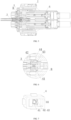
FIG. 1 illustrates a schematic diagram of a high-voltage connector for jogging control over high-voltage inter-lock according to the present disclosure when a high-voltage inter-lock system is switched on; -
FIG. 2 illustrates a cross-sectional view taken along A-A inFIG. 1 when a jogging control slider is adopted for a jogging control structure according to the present disclosure; -
FIG. 3 illustrates an enlarged view taken at I inFIG. 2 ; -
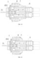
FIG. 4 illustrates a schematic diagram of a high-voltage connector for jogging control over high-voltage inter-lock according to the present disclosure when a high-voltage inter-lock system is switched off; -
FIG. 5 illustrates a cross-sectional view taken along B-B inFIG. 4 when a jogging control slider is adopted for a jogging control structure according to the present disclosure; -
FIG. 6 illustrates an enlarged view taken at II inFIG. 5 ; -
FIG. 7 illustrates an assembly diagram of a jogging control structure according to the present disclosure; -
FIG. 8 illustrates an exploded diagram of a jogging control structure according to the present disclosure; -
FIG. 9 illustrates a structural diagram of a high-voltage inter-lock ejector block according to the present disclosure; -
FIG. 10 illustrates a structural diagram of a high-voltage inter-lock terminal according to the present disclosure; -
FIG. 11 illustrates an exploded diagram of a socket housing structure before being assembled according to the present disclosure; -
FIG. 12 illustrates a schematic diagram of a socket housing structure after being assembled according to the present disclosure; -
FIG. 13 illustrates an exploded diagram of a plug housing structure before being assembled according to the present disclosure; -
FIG. 14 illustrates a schematic diagram of a plug housing structure after being assembled according to the present disclosure; -
FIG. 15 illustrates a principle diagram when a high-voltage connector for jogging control over high-voltage inter-lock according to the present disclosure is unplugged; -
FIG. 16 illustrates a principle diagram when a high-voltage connector for jogging control over high-voltage inter-lock according to the present disclosure is plugged; -
FIG. 17 illustrates a principle diagram when a high-voltage connector of the prior art is unplugged; -
FIG. 18 illustrates a principle diagram when a high-voltage connector of the prior art is plugged; -
FIG. 19 illustrates a schematic diagram when a positioning projection is provided on a jogging control housing according to the present disclosure; -
FIG. 20 illustrates a schematic diagram when a positioning block is provided in a socket housing according to the present disclosure; -
FIG. 21 illustrates a schematic diagram of a process of mounting a microswitch on a socket housing; -
FIG. 22 illustrates a schematic diagram of a rear end of a socket housing on which a microswitch is mounted; -
FIG. 23 illustrates a schematic diagram of a front end of a socket housing on which a microswitch is mounted; -
FIG. 24 illustrates a cross-sectional view taken along A-A inFIG. 1 when a microswitch is adopted for a jogging control structure according to the present disclosure; and -
FIG. 25 illustrates a cross-sectional view taken along B-B inFIG. 4 when a microswitch is adopted for a jogging control structure according to the present disclosure. - In the drawings,
100: high-voltage connector for jogging control over high-voltage inter-lock; 1: socket housing; 11: connecting post; 12: positioning block; 13: positioning clamping groove; 14: positioning claw; 2: dual self-locking structure; 3: high-voltage inter-lock terminal; 31: transition signal line; 4: jogging control structure; 41: return spring; 42: high-voltage inter-lock short-distance connection reed; 421: first accommodating curved groove; 422: second accommodating curved groove; 423: connecting tab; 424: reed insertion portion; 43: jogging control slider; 431: guide post; 432: slider body; 433: reed connecting plate; 434: tab clamping groove; 435: reed plugging groove; 44: jogging control housing; 441: guide post through-hole; 442: positioning protrusion; 45: microswitch; 451: switch housing; 452: switch button; 5: high-voltage male terminal; 6: plug housing; 7: rocker arm; 8: high-voltage inter-lock ejector block; 81: ejector block enclosure frame; 82: abutting hole; 9: high-voltage female terminal; 201: pin terminal; 202: jack terminal. - For a clearer understanding of the technical features, objectives and effects of the present disclosure, specific embodiments of the present disclosure will now be described with reference to the drawings.
- The specific embodiments of the present disclosure described here are only for the purpose of explaining the present disclosure, and should not be construed as limiting the present disclosure in any way. Under the teaching of the present disclosure, persons skilled in the art can conceive any possible variation based on the present disclosure, which should be regarded as falling within the scope of the present disclosure. It should be noted that when an element is referred to as being "provided" on another element, it may be directly on another element or there may be an intervening element. When an element is regarded as being "connected" to another element, it may be directly connected to another element or there may be an intervening element. The terms 'mount' and 'connect' should be understood in a broad sense. For example, a connection may be a mechanical connection or an electrical connection, or an internal communication between two elements, or a direct connection, or an indirect connection through an intermediate medium. For persons of ordinary skills in the art, the specific meanings of the above terms can be understood according to the specific conditions. The terms "vertical", "horizontal", "upper", "lower", "left", "right" and similar expressions used herein are for illustration only rather than indicating a unique embodiment.
- Unless otherwise defined, all technical and scientific terms used herein have the same meanings as those commonly understood by persons skilled in the art of the present disclosure. The terms used in the Specification of the present disclosure are only for the purpose of describing the specific embodiments, rather than limiting the present disclosure. The term "and/or" used herein includes any and all combinations of one or more of the related items listed.
- As illustrated in
FIGS. 1 to 14 and19 to 25 , the present disclosure provides a high-voltage connector 100 for jogging control over high-voltage inter-lock, including asocket housing 1 and aplug housing 6. A high-voltage male terminal 5 and a high-voltagefemale terminal 9, which are electrically connectable to each other by being plugged with each other, are provided in thesocket housing 1 and theplug housing 6, respectively (as illustrated inFIGS. 12 and14 ). The high-voltage connector further includes a high-voltage inter-lock system configured to control an electrical connectivity state between the high-voltage male terminal 5 and the high-voltagefemale terminal 9. By plugging the high-voltage male terminal 5 and the high-voltagefemale terminal 9 with each other and further moving them toward each other for a first distance, the high-voltage inter-lock system is powered on, and then the high-voltage male terminal 5 and the high-voltagefemale terminal 9 are electrically connected; by moving the high-voltage male terminal 5 and the high-voltagefemale terminal 9 away from each other for the first distance, the high-voltage inter-lock system is powered off and at the same time the high-voltage male terminal 5 and the high-voltagefemale terminal 9 are electrically disconnected, and by further moving the high-voltage male terminal 5 and the high-voltagefemale terminal 9 away from each other for a second distance, they are separated from each other. - The high-voltage inter-lock system is provided with a jogging
control structure 4 capable of controlling the high-voltage inter-lock system to be powered on or powered off by means of a short-distance action, so as to control an electrical connectivity state between the high-voltage male terminal 5 and the high-voltagefemale terminal 9. The term "short-distance" refers to the on-off control distance of the jogging control structure being much shorter than the plug-unplug distance of the existing pin-jack type high-voltage inter-lock device. - As illustrated in
FIGS. 15 and 16 , when an operator unlocks a dual lock and just starts to unplug the high-voltage connector (the jogging control structure can be switched off within an extremely short distance and an extremely short period of time), the high-voltage inter-lock system is switched off, and a high-voltage loop is immediately powered off (i.e., the high-voltage male terminal and the high-voltage female terminal are electrically disconnected). When the operator plugs the high-voltage connector, only at a moment at which the plugging between the high-voltage male terminal and the high-voltage female terminal is completed, the high-voltage inter-lock system is switched on and the high-voltage loop is powered on (i.e., the high-voltage male terminal and the high-voltage female terminal are electrically connected), which effectively solves the problem of live-line plugging and unplugging of the high-voltage connector during plugging and unplugging, reduces the potential safety hazards when plugging and unplugging the high-voltage connector, and ensures the personal safety of the operator. - The existing high-voltage inter-lock devices are all of a pin-jack type, and during plugging of the high-voltage connector, the high-voltage inter-lock terminal has a long reassembly time and a long plugging distance, which leads to a long distance of live-line plugging and unplugging of the high-voltage connector. The high-voltage connector for jogging control over high-voltage inter-lock of the present disclosure is provided with a jogging control structure, which can realize jogging control over high-voltage inter-lock, such that a high-voltage inter-lock system can be switched on and switched off within an extremely short period of time, thereby greatly reducing the reassembly time and the plugging distance, reducing the distance of live-line plugging and unplugging, achieving the jogging control, reducing the potential safety hazards, and ensuring the connection stability of the high-voltage inter-lock system.
- Further, as illustrated in
FIGS. 2 ,3 ,5, 6, 7 and8 , the high-voltage inter-lock system includes two high-voltage inter-lock terminals 3 provided in the socket housing, and the joggingcontrol structure 4 includes ajogging control housing 44 provided in thesocket housing 1 and a high-voltageinter-lock ejector block 8 provided in theplug housing 6. A high-voltage inter-lock short-distance connection reed 42 is slidably provided in thejogging control housing 44, and the high-voltageinter-lock ejector block 8 is capable of ejecting and pushing the high-voltage inter-lock short-distance connection reed 42 to slide to be electrically connected to the high-voltage inter-lock terminals 3. - Further, as illustrated in
FIGS. 2 ,3 ,5, 6, 7 and8 , a joggingcontrol slider 43 is slidably provided in thejogging control housing 44, the high-voltage inter-lock short-distance connection reed 42 is connected to a side of the joggingcontrol slider 43 away from the high-voltageinter-lock ejector block 8, and areturn spring 41 is provided on and abutted against a side of the high-voltage inter-lock short-distance connection reed 42 away from the high-voltageinter-lock ejector block 8; the high-voltageinter-lock ejector block 8 is capable of ejecting and pushing the joggingcontrol slider 43 and the high-voltage inter-lock short-distance connection reed 42 to slide towards the high-voltage inter-lock terminals 3, and thereturn spring 41 is capable of pushing the joggingcontrol slider 43 to slide away from the high-voltage inter-lock terminals 3. - Further, as illustrated in
FIGS. 2 ,3 ,5, 6, 7 and8 , a side of thejogging control housing 44 close to the high-voltage inter-lock terminals is provided with an opening, a sidewall of thejogging control housing 44 away from the high-voltage inter-lock terminals 3 is provided with a guide post through-hole 441, and the joggingcontrol slider 43 is provided with aguide post 431 slidably inserted into the guide post through-hole 441; the high-voltageinter-lock ejector block 8 is capable of ejecting theguide post 431 to push thejogging control slider 43. - Further, as illustrated in
FIG. 8 , the high-voltage inter-lock short-distance connection reed 42 is bent in a bow shape to form a first accommodatingcurved groove 421, two sides of which form a second accommodatingcurved groove 422, respectively, and thereturn spring 41 is provided in the first accommodatingcurved groove 421. The joggingcontrol slider 43 includes aslider body 432 provided with tworeed connecting plates 433 which can be clamped in the second accommodatingcurved groove 422, respectively. - As illustrated in
FIGS. 19 and 20 , in this embodiment, apositioning block 12 is provided in thesocket housing 1, apositioning clamping groove 13 is provided on thepositioning block 12, apositioning protrusion 442 is provided on thejogging control housing 44, and thepositioning protrusion 442 can be clamped in thepositioning clamping groove 13. In this embodiment, the number of the positioningprotrusions 442 and the number of thepositioning clamping grooves 13 are four. - Further, as illustrated in
FIG. 8 , two sidewalls of the first accommodatingcurved groove 421 are provided with a connectingtab 423, respectively, the tworeed connecting plates 433 are provided with atab clamping groove 434, respectively, and each of the connectingtabs 423 can be clamped in the correspondingtab clamping groove 434. - Further, as illustrated in
FIG. 8 , two ends of the high-voltage inter-lock short-distance connection reed 42 are provided with areed insertion portion 424, respectively, theslider body 432 is provided withreed plugging grooves 435, and thereed insertion portions 424 can be plugged into thereed plugging grooves 435, respectively. - Further, as illustrated in
FIG. 9 , the high-voltageinter-lock ejector block 8 is provided on an ejectorblock enclosure frame 81, which can be detachably clamped in theplug housing 6; an end of the high-voltageinter-lock ejector block 8 is provided with an abuttinghole 82, which can abut against theguide post 431 to push theguide post 431 to slide. - Further, as illustrated in
FIGS. 10 and11 , the high-voltage inter-lock terminals 3 are plugged into thesocket housing 1 from an end away from the plug housing (i.e., a tail of the socket housing), and the high-voltage inter-lock terminals 3 are locked and fixed in thesocket housing 1 by a dual self-lockingstructure 2. The dual self-lockingstructure 2 may be a Terminal Position Assurance (TPA) clip, which can lock the terminals and enhance the retention of the terminals in the connector. The TPA achieves a dual protection and limiting for the terminals in the connector, and is also known as a dual self-locking structure, which is applied in a harsh environment or when a greater unplugging force is required. The TPA is plugged to lock the high-voltage inter-lock terminals, and when the high-voltage inter-lock terminals are matched with the TPA, the movement of the high-voltage inter-lock terminals is well limited, which achieves an anti-retreat function and ensures the connection stability of the high-voltage inter-lock. - In another specific embodiment of the present disclosure, the jogging
control housing 44, the joggingcontrol slider 43, the high-voltage inter-lock short-distance connection reed 42 and thereturn spring 41 in the aforementionedjogging control structure 4 may be replaced with a microswitch, which may be a microswitch in the prior art. - Further, as illustrated in
FIGS. 21 to 25 , the joggingcontrol structure 4 includes amicroswitch 45 provided in thesocket housing 1 and a high-voltageinter-lock ejector block 8 provided in theplug housing 6. Themicroswitch 45 includes aswitch housing 451 and aswitch button 452, a first end of theswitch button 452 protrudes out of theswitch housing 451, and a second end of theswitch button 452 can be electrically connected to twotransition signal lines 31, which are electrically connected to the high-voltage inter-lock system. The high-voltageinter-lock ejector block 8 can eject and push theswitch button 452 to power on the high-voltage inter-lock system. Further, as illustrated inFIGS. 21 and 22 , thesocket housing 1 is provided with a switch through-hole having a shape matched with a shape of theswitch housing 451. A side (rear end) of the switch through-hole away from theplug housing 6 is provided with apositioning claw 14, and theswitch housing 451 is inserted into the switch through-hole and is fixed by thepositioning claw 14. In this embodiment, theswitch housing 451 has a rectangular cross section, and the number of the positioningclaws 14 are four, and the fourpositioning claws 14 are clamped and abutted against four sides of theswitch housing 451, respectively. - As illustrated in
FIGS. 21, 22 and 23 , during mounting, the second end of theswitch button 452 is connected to twotransition signal lines 31, and themicroswitch 45 is plugged into thesocket housing 1 from a rear end of the socket housing 1 (i.e., a side of thesocket housing 1 away from the plug housing 6). Thepositioning claw 14 blocks theswitch housing 451 of themicroswitch 45 to prevent themicroswitch 45 from retreating, thereby achieving an anti-retreat function; thesocket house 1 restricts themicroswitch 45 from moving forward. During plugging, the high-voltageinter-lock ejector block 8 ejects and pushes theswitch button 452; when the high-voltage connector is about to be reassembled in place, themicroswitch 45 is closed, the high-voltage inter-lock system is switched on, and the high-voltage loop, where the high-voltage male terminal 5 is electrically connected to the high-voltagefemale terminal 9, is powered on, such that the plugging of the high-voltage connector is completed, as illustrated inFIG. 24 . When the high-voltage connector is unplugged, the high-voltageinter-lock ejector block 8 is separated from themicroswitch 45, the high-voltage inter-lock system is switched off, and the high-voltage loop, where the high-voltage male terminal 5 is electrically connected to the high-voltagefemale terminal 9, is powered off, as illustrated inFIG. 25 . - Further, as illustrated in
FIGS. 1 ,4 ,11, 12 ,13 and 14 , arocker arm 7 is provided on a sidewall of theplug housing 6, a connecting groove is provided on therocker arm 7, a connectingpost 11 is provided on a sidewall of thesocket housing 1, and the connecting groove is disposed to slidably sleeve the connectingpost 11. - The use process of the high-
voltage connector 100 for jogging control over high-voltage inter-lock of the present disclosure is as follows:
During plugging, the high-voltagefemale terminal 9 moves forward along with theplug housing 6, and continues to move forward after being contacted with the high-voltage male terminal 5 in thesocket housing 1. At this time, the high-voltageinter-lock ejector block 8 in theplug housing 6 has not been contacted with the jogging control slider 43 (i.e., guide post 431) in thesocket housing 1, and the high-voltage inter-lock system is not switched on, such that the high-voltage male terminal 5 and the high-voltagefemale terminal 9 are in a powered off state. When therocker arm 7 is about to be reassembled in place, the high-voltageinter-lock ejector block 8 is contacted with theguide post 431 of the joggingcontrol slider 43, and the high-voltageinter-lock ejector block 8 pushes the joggingcontrol slider 43 to slide until the high-voltage inter-lock short-distance connection reed 42 is completely in close contact with the high-voltage inter-lock terminals 3. At this time, thereturn spring 41 is compressed, the high-voltage inter-lock system is switched on, the high-voltage loop, where the high-voltage male terminal 5 is electrically connected to the high-voltagefemale terminal 9, is powered on, and the plugging of the high-voltage connector is completed, as illustrated inFIGS. 1, 2 and3 . From the time when the high-voltage inter-lock short-distance connection reed 42 starts to come into contact with the high-voltage inter-lock terminals 3 until the completion of the plugging of the high-voltage connector, a relative movement distance between the high-voltage male terminal 5 and the high-voltagefemale terminal 9 is very short, which greatly reduces the distance of live-line plugging and unplugging and reduces the potential safety hazards. - During unplugging, the
rocker arm 7 is lifted upward, theplug housing 6 starts to move backwards, and the high-voltageinter-lock ejector block 8 in theplug housing 6 also starts to move backwards. At this time, thereturn spring 41 urges the joggingcontrol slider 43 to move backwards until the high-voltage inter-lockshort reed 42 is completely separated from the high-voltage inter-lock terminals 3. At this time, the high-voltage loop, where the high-voltage male terminal 5 is electrically disconnected from the high-voltagefemale terminal 9, is powered off, and theplug housing 6 and the high-voltagefemale terminal 9 therein only move for a very short distance, as illustrated inFIGS. 4 ,5 and 6 . As theplug housing 6 continues to move backwards, the high-voltage male terminal 5 and the high-voltagefemale terminal 9 are completely separated from each other. During unplugging, a live-line unplugging distance of the high-voltage connector is greatly shortened, and the potential safety hazards are reduced. - Based on the above description, the high-voltage connector for jogging control over high-voltage inter-lock of the present disclosure has the following advantageous effects:
The high-voltage connector for jogging control over high-voltage inter-lock of the present disclosure is provided with a jogging control structure, which can realize jogging control over high-voltage inter-lock, such that the high-voltage inter-lock system can be switched on and switched off within an extremely short period of time, thereby greatly reducing the reassembly time and the plugging distance, reducing the distance of hot plugging and unplugging, achieving the jogging control, reducing the potential safety hazards, and ensuring the connection stability of the high-voltage inter-lock system. The present disclosure effectively solves the problem of live-line plugging and unplugging of the high-voltage connector during plugging and unplugging, reduces the potential safety hazards during plugging and unplugging of the high-voltage connector, and ensures the personal safety of operators. - Those described above are just schematic embodiments of the present disclosure, rather than limitations thereto. Any equivalent substitution or amendment made by persons skilled in the art without deviating from the concept and principle of the present disclosure should fall within the protection scope of the present disclosure.
Claims (12)
- A high-voltage connector for jogging control over high-voltage inter-lock, comprising a socket housing and a plug housing, wherein a high-voltage male terminal and a high-voltage female terminal, which are electrically connectable to each other by being plugged with each other, are provided in the socket housing and the plug housing, respectively; and
the high-voltage connector further comprises a high-voltage inter-lock system, on which a jogging control structure is provided, wherein the jogging control structure is configured to control, by means of a short-distance action, the high-voltage inter-lock system to be powered on or powered off, so as to control an electrical connectivity state between the high-voltage male terminal and the high-voltage female terminal. - The high-voltage connector for jogging control over high-voltage inter-lock according to claim 1, wherein the high-voltage inter-lock system comprises two high-voltage inter-lock terminals provided in the socket housing, and the jogging control structure comprises a jogging control housing provided in the socket housing and a high-voltage inter-lock ejector block provided in the plug housing; and
a high-voltage inter-lock short-distance connection reed is slidably provided in the jogging control housing, and the high-voltage inter-lock ejector block is capable of ejecting and pushing the high-voltage inter-lock short-distance connection reed to slide to be electrically connected to the high-voltage inter-lock terminals. - The high-voltage connector for jogging control over high-voltage inter-lock according to claim 2, wherein a jogging control slider is slidably provided in the jogging control housing, the high-voltage inter-lock short-distance connection reed is connected to a side of the jogging control slider away from the high-voltage inter-lock ejector block, and a return spring is provided on and abutted against a side of the high-voltage inter-lock short-distance connection reed away from the high-voltage inter-lock ejector block; and
the high-voltage inter-lock ejector block is capable of ejecting and pushing the jogging control slider and the high-voltage inter-lock short-distance connection reed to slide towards the high-voltage inter-lock terminals, and the return spring is capable of pushing the jogging control slider to slide away from the high-voltage inter-lock terminals. - The high-voltage connector for jogging control over high-voltage inter-lock according to claim 3, wherein a side of the jogging control housing close to the high-voltage inter-lock terminals is provided with an opening, a sidewall of the jogging control housing away from the high-voltage inter-lock terminals is provided with a guide post through-hole, and the jogging control slider is provided with a guide post slidably inserted into the guide post through-hole; and
the high-voltage inter-lock ejector block is capable of ejecting the guide post to push the jogging control slider. - The high-voltage connector for jogging control over high-voltage inter-lock according to claim 3, wherein the high-voltage inter-lock short-distance connection reed is bent in a bow shape to form a first accommodating curved groove, two sides of which form a second accommodating curved groove, respectively, and the return spring is provided in the first accommodating curved groove; and
the jogging control slider comprises a slider body provided with two reed connecting plates which are clamped in the second accommodating curved grooves, respectively. - The high-voltage connector for jogging control over high-voltage inter-lock according to claim 5, wherein two sidewalls of the first accommodating curved groove are provided with a connecting tab, respectively, the two reed connecting plates are provided with a tab clamping groove, respectively, and each of the connecting tabs is clamped in the corresponding tab clamping groove.
- The high-voltage connector for jogging control over high-voltage inter-lock according to claim 5, wherein two ends of the high-voltage inter-lock short-distance connection reed are provided with a reed insertion portion, respectively, the slider body is provided with reed plugging grooves, and the reed insertion portions are inserted into the reed plugging grooves, respectively.
- The high-voltage connector for jogging control over high-voltage inter-lock according to claim 5, wherein a positioning block is provided in the socket housing, a positioning clamping groove is provided on the positioning block, a positioning protrusion is provided on the jogging control housing, and the positioning protrusion is clamped in the positioning clamping groove.
- The high-voltage connector for jogging control over high-voltage inter-lock according to claim 4, wherein the high-voltage inter-lock ejector block is provided on an ejector block enclosure frame, which is detachably clamped in the plug housing; and
an end of the high-voltage inter-lock ejector block is provided with an abutting hole, which is capable of abutting against the guide post to push the guide post to slide. - The high-voltage connector for jogging control over high-voltage inter-lock according to claim 4, wherein the high-voltage inter-lock terminals are plugged into the socket housing from an end away from the plug housing, and the high-voltage inter-lock terminals are locked and fixed in the socket housing by a dual self-locking structure.
- The high-voltage connector for jogging control over high-voltage inter-lock according to claim 1, wherein the jogging control structure comprises a microswitch provided in the socket housing and a high-voltage inter-lock ejector block provided in the plug housing;the microswitch comprises a switch housing and a switch button, a first end of the switch button protrudes out of the switch housing, and a second end of the switch button is capable of being electrically connected to two transition signal lines, which are electrically connected to the high-voltage inter-lock system; andthe high-voltage inter-lock ejector block is capable of ejecting and pushing the switch button to power on the high-voltage inter-lock system.
- The high-voltage connector for jogging control over high-voltage inter-lock according to claim 11, wherein the socket housing is provided with a switch through-hole, a side of the switch through-hole away from the plug housing is provided with a positioning claw, and the switch housing is inserted into the switch through-hole and is fixed by the positioning claw.
Applications Claiming Priority (2)
| Application Number | Priority Date | Filing Date | Title |
|---|---|---|---|
| CN202210176329.8A CN114498193A (en) | 2022-02-24 | 2022-02-24 | Micro-controlled high-voltage interlock high-voltage connectors |
| PCT/CN2023/076686 WO2023160464A1 (en) | 2022-02-24 | 2023-02-17 | High-voltage connector capable of realizing jogging control over high-voltage inter-lock |
Publications (3)
| Publication Number | Publication Date |
|---|---|
| EP4485709A1 true EP4485709A1 (en) | 2025-01-01 |
| EP4485709A4 EP4485709A4 (en) | 2025-05-21 |
| EP4485709B1 EP4485709B1 (en) | 2026-05-13 |
Family
ID=81483921
Family Applications (1)
| Application Number | Title | Priority Date | Filing Date |
|---|---|---|---|
| EP23759089.8A Active EP4485709B1 (en) | 2022-02-24 | 2023-02-17 | High-voltage connector capable of realizing jogging control over high-voltage inter-lock |
Country Status (5)
| Country | Link |
|---|---|
| US (1) | US20250192478A1 (en) |
| EP (1) | EP4485709B1 (en) |
| CN (1) | CN114498193A (en) |
| MX (1) | MX2024010436A (en) |
| WO (1) | WO2023160464A1 (en) |
Families Citing this family (3)
| Publication number | Priority date | Publication date | Assignee | Title |
|---|---|---|---|---|
| CN114498193A (en) * | 2022-02-24 | 2022-05-13 | 长春捷翼汽车零部件有限公司 | Micro-controlled high-voltage interlock high-voltage connectors |
| CN117854957A (en) * | 2022-09-30 | 2024-04-09 | 哈廷电子基金会两合公司 | Switchgear for high voltage interlock circuit system |
| CN118448939B (en) * | 2024-07-08 | 2024-09-03 | 深圳市德兰明海新能源股份有限公司 | Connector and energy storage device |
Family Cites Families (5)
| Publication number | Priority date | Publication date | Assignee | Title |
|---|---|---|---|---|
| CN104577552B (en) * | 2014-12-11 | 2017-01-25 | 华晨汽车集团控股有限公司 | Automobile high-voltage connector interlocking mechanism |
| KR101734670B1 (en) * | 2015-08-26 | 2017-05-11 | 현대자동차주식회사 | High voltage connector for vehicle |
| CN207602930U (en) * | 2017-12-05 | 2018-07-10 | 上海航天科工电器研究院有限公司 | A kind of high-voltage electric connector of interlocking loop |
| CN114498193A (en) * | 2022-02-24 | 2022-05-13 | 长春捷翼汽车零部件有限公司 | Micro-controlled high-voltage interlock high-voltage connectors |
| CN217444755U (en) * | 2022-02-24 | 2022-09-16 | 长春捷翼汽车零部件有限公司 | High-voltage connector with micro-motion control high-voltage interlocking |
-
2022
- 2022-02-24 CN CN202210176329.8A patent/CN114498193A/en active Pending
-
2023
- 2023-02-17 EP EP23759089.8A patent/EP4485709B1/en active Active
- 2023-02-17 US US18/840,797 patent/US20250192478A1/en active Pending
- 2023-02-17 MX MX2024010436A patent/MX2024010436A/en unknown
- 2023-02-17 WO PCT/CN2023/076686 patent/WO2023160464A1/en not_active Ceased
Also Published As
| Publication number | Publication date |
|---|---|
| EP4485709A4 (en) | 2025-05-21 |
| US20250192478A1 (en) | 2025-06-12 |
| MX2024010436A (en) | 2024-09-05 |
| EP4485709B1 (en) | 2026-05-13 |
| CN114498193A (en) | 2022-05-13 |
| WO2023160464A1 (en) | 2023-08-31 |
Similar Documents
| Publication | Publication Date | Title |
|---|---|---|
| EP4485709B1 (en) | High-voltage connector capable of realizing jogging control over high-voltage inter-lock | |
| US4034172A (en) | High voltage connector with crow bar | |
| US10148034B2 (en) | Arcless power connector | |
| CN212304087U (en) | Quick plugging electric connector | |
| US8573993B2 (en) | Connector | |
| CN105655802A (en) | High-voltage connector for vehicle and locking and unlocking method of connector | |
| CN212725793U (en) | Secondary locking high-voltage interlocking connector | |
| CN102856689B (en) | Connector | |
| CN206148689U (en) | Novel high voltage connector | |
| CN118073896B (en) | A high voltage interlocking corner connector and connector assembly | |
| CN217444755U (en) | High-voltage connector with micro-motion control high-voltage interlocking | |
| CN106384914B (en) | Power off tripper | |
| CN109901073B (en) | Opposite insertion device, battery module charging and discharging detection system and automatic opposite insertion method | |
| US6485318B1 (en) | Electrical shuttle connector | |
| CN221176803U (en) | Electric connector | |
| CN116231398A (en) | High-voltage temperature control connector | |
| CN205900999U (en) | A kind of anti-open circuit connector | |
| CN213782390U (en) | Electric connector with time delay unlocking mechanism | |
| CN216872371U (en) | Electric connector opening and closing structure and battery box assembly | |
| CN106058528B (en) | An electrical connector contact piece, electrical connector and short-circuit electrical connector | |
| CN216121063U (en) | Socket with forced-release switch | |
| CN219998613U (en) | High-voltage connector protection lock catch structure for automobile | |
| CN223927834U (en) | An automated electrical socket | |
| CN222883982U (en) | A compact quick-release plug-in power connector | |
| CN222995867U (en) | Built-in channel plug connector and connector assembly |
Legal Events
| Date | Code | Title | Description |
|---|---|---|---|
| STAA | Information on the status of an ep patent application or granted ep patent |
Free format text: STATUS: THE INTERNATIONAL PUBLICATION HAS BEEN MADE |
|
| PUAI | Public reference made under article 153(3) epc to a published international application that has entered the european phase |
Free format text: ORIGINAL CODE: 0009012 |
|
| STAA | Information on the status of an ep patent application or granted ep patent |
Free format text: STATUS: REQUEST FOR EXAMINATION WAS MADE |
|
| 17P | Request for examination filed |
Effective date: 20240917 |
|
| AK | Designated contracting states |
Kind code of ref document: A1 Designated state(s): AL AT BE BG CH CY CZ DE DK EE ES FI FR GB GR HR HU IE IS IT LI LT LU LV MC ME MK MT NL NO PL PT RO RS SE SI SK SM TR |
|
| REG | Reference to a national code |
Ref country code: DE Ref legal event code: R079 Free format text: PREVIOUS MAIN CLASS: H01R0013639000 Ipc: H01R0013530000 Ref country code: DE Ref legal event code: R079 Ref document number: 602023017289 Country of ref document: DE Free format text: PREVIOUS MAIN CLASS: H01R0013639000 Ipc: H01R0013530000 |
|
| A4 | Supplementary search report drawn up and despatched |
Effective date: 20250425 |
|
| RIC1 | Information provided on ipc code assigned before grant |
Ipc: H01R 13/629 20060101ALN20250417BHEP Ipc: H01R 24/00 20110101ALI20250417BHEP Ipc: H01R 13/70 20060101ALI20250417BHEP Ipc: H01R 13/639 20060101ALI20250417BHEP Ipc: H01R 13/627 20060101ALI20250417BHEP Ipc: H01R 13/53 20060101AFI20250417BHEP |
|
| DAV | Request for validation of the european patent (deleted) | ||
| DAX | Request for extension of the european patent (deleted) | ||
| P01 | Opt-out of the competence of the unified patent court (upc) registered |
Free format text: CASE NUMBER: APP_22606/2025 Effective date: 20250513 |
|
| GRAP | Despatch of communication of intention to grant a patent |
Free format text: ORIGINAL CODE: EPIDOSNIGR1 |
|
| STAA | Information on the status of an ep patent application or granted ep patent |
Free format text: STATUS: GRANT OF PATENT IS INTENDED |
|
| INTG | Intention to grant announced |
Effective date: 20251222 |
|
| RIC1 | Information provided on ipc code assigned before grant |
Ipc: H01R 13/53 20060101AFI20251215BHEP Ipc: H01R 13/627 20060101ALI20251215BHEP Ipc: H01R 13/639 20060101ALI20251215BHEP Ipc: H01R 13/70 20060101ALI20251215BHEP Ipc: H01R 24/00 20110101ALI20251215BHEP Ipc: H01R 13/629 20060101ALN20251215BHEP |
|
| GRAS | Grant fee paid |
Free format text: ORIGINAL CODE: EPIDOSNIGR3 |
|
| GRAA | (expected) grant |
Free format text: ORIGINAL CODE: 0009210 |
|
| STAA | Information on the status of an ep patent application or granted ep patent |
Free format text: STATUS: THE PATENT HAS BEEN GRANTED |
|
| AK | Designated contracting states |
Kind code of ref document: B1 Designated state(s): AL AT BE BG CH CY CZ DE DK EE ES FI FR GB GR HR HU IE IS IT LI LT LU LV MC ME MK MT NL NO PL PT RO RS SE SI SK SM TR |
|
| REG | Reference to a national code |
Ref country code: CH Ref legal event code: F10 Free format text: ST27 STATUS EVENT CODE: U-0-0-F10-F00 (AS PROVIDED BY THE NATIONAL OFFICE) Effective date: 20260513 |