EP4485676A1 - Electrode plate and method of preparing electrode plate - Google Patents
Electrode plate and method of preparing electrode plate Download PDFInfo
- Publication number
- EP4485676A1 EP4485676A1 EP24172490.5A EP24172490A EP4485676A1 EP 4485676 A1 EP4485676 A1 EP 4485676A1 EP 24172490 A EP24172490 A EP 24172490A EP 4485676 A1 EP4485676 A1 EP 4485676A1
- Authority
- EP
- European Patent Office
- Prior art keywords
- electrode plate
- region
- edge
- cutting
- tab
- Prior art date
- Legal status (The legal status is an assumption and is not a legal conclusion. Google has not performed a legal analysis and makes no representation as to the accuracy of the status listed.)
- Pending
Links
Images


Classifications
-
- H—ELECTRICITY
- H01—ELECTRIC ELEMENTS
- H01M—PROCESSES OR MEANS, e.g. BATTERIES, FOR THE DIRECT CONVERSION OF CHEMICAL ENERGY INTO ELECTRICAL ENERGY
- H01M4/00—Electrodes
- H01M4/02—Electrodes composed of, or comprising, active material
- H01M4/13—Electrodes for accumulators with non-aqueous electrolyte, e.g. for lithium-accumulators; Processes of manufacture thereof
-
- H—ELECTRICITY
- H01—ELECTRIC ELEMENTS
- H01M—PROCESSES OR MEANS, e.g. BATTERIES, FOR THE DIRECT CONVERSION OF CHEMICAL ENERGY INTO ELECTRICAL ENERGY
- H01M50/00—Constructional details or processes of manufacture of the non-active parts of electrochemical cells other than fuel cells, e.g. hybrid cells
- H01M50/50—Current conducting connections for cells or batteries
- H01M50/531—Electrode connections inside a battery casing
- H01M50/533—Electrode connections inside a battery casing characterised by the shape of the leads or tabs
-
- B—PERFORMING OPERATIONS; TRANSPORTING
- B23—MACHINE TOOLS; METAL-WORKING NOT OTHERWISE PROVIDED FOR
- B23K—SOLDERING OR UNSOLDERING; WELDING; CLADDING OR PLATING BY SOLDERING OR WELDING; CUTTING BY APPLYING HEAT LOCALLY, e.g. FLAME CUTTING; WORKING BY LASER BEAM
- B23K26/00—Working by laser beam, e.g. welding, cutting or boring
- B23K26/36—Removing material
- B23K26/38—Removing material by boring or cutting
-
- H—ELECTRICITY
- H01—ELECTRIC ELEMENTS
- H01M—PROCESSES OR MEANS, e.g. BATTERIES, FOR THE DIRECT CONVERSION OF CHEMICAL ENERGY INTO ELECTRICAL ENERGY
- H01M10/00—Secondary cells; Manufacture thereof
- H01M10/05—Accumulators with non-aqueous electrolyte
- H01M10/052—Li-accumulators
- H01M10/0525—Rocking-chair batteries, i.e. batteries with lithium insertion or intercalation in both electrodes; Lithium-ion batteries
-
- H—ELECTRICITY
- H01—ELECTRIC ELEMENTS
- H01M—PROCESSES OR MEANS, e.g. BATTERIES, FOR THE DIRECT CONVERSION OF CHEMICAL ENERGY INTO ELECTRICAL ENERGY
- H01M4/00—Electrodes
- H01M4/02—Electrodes composed of, or comprising, active material
- H01M4/13—Electrodes for accumulators with non-aqueous electrolyte, e.g. for lithium-accumulators; Processes of manufacture thereof
- H01M4/139—Processes of manufacture
-
- Y—GENERAL TAGGING OF NEW TECHNOLOGICAL DEVELOPMENTS; GENERAL TAGGING OF CROSS-SECTIONAL TECHNOLOGIES SPANNING OVER SEVERAL SECTIONS OF THE IPC; TECHNICAL SUBJECTS COVERED BY FORMER USPC CROSS-REFERENCE ART COLLECTIONS [XRACs] AND DIGESTS
- Y02—TECHNOLOGIES OR APPLICATIONS FOR MITIGATION OR ADAPTATION AGAINST CLIMATE CHANGE
- Y02E—REDUCTION OF GREENHOUSE GAS [GHG] EMISSIONS, RELATED TO ENERGY GENERATION, TRANSMISSION OR DISTRIBUTION
- Y02E60/00—Enabling technologies; Technologies with a potential or indirect contribution to GHG emissions mitigation
- Y02E60/10—Energy storage using batteries
Definitions
- the present disclosure relates to the field of battery technologies, and more particularly, to an electrode plate, a battery, an electric apparatus, and a method of preparing the electrode plate.
- the tab is the metal conductor that leads positive and negative electrodes out of the battery cell, and the complete tab is mainly composed of the insulating sealant and the metal conductive substrate.
- the material, the size, and the lead-out way of the tab have a great influence on the multiplicity discharge performance and multiplicity cycle performance of the lithium-ion battery.
- the magnitude of the energizing current is proportional to the cross-section of the wire, i.e., the larger the cross-section area of the wire, the larger the current is allowed to pass through the wire.
- the size of the tab is not only determined by the model of the battery, but also depends on the maximum discharging current required by the battery. Therefore, the shape of the tab is crucial in the structure of the battery.
- the tab may be deformed or damaged by the cutting waste material when cutting, which affects the overcurrent capability and consistency of the tab, and seriously leads to the scrapping of the electrode plate.
- the cutting method of the existing tab structure also limits the running speed of the apparatus. When the running speed of the apparatus is over 100m/min, there is a risk of cutting limitation, and the laser track cannot match the running speed of the apparatus.
- an object of the present disclosure is to provide an electrode plate, a battery, an electric apparatus, and a method of preparing the electrode plate.
- the integrity of a tab shape is ensured, and a maximum current allowed to pass through the tab is ensured.
- the charging and discharging efficiency of the lithium-ion battery is ensured.
- an electrode plate in one aspect of the present disclosure, includes an electrode plate body and a tab located at least one end of the electrode plate body in a width direction of the electrode plate body.
- the tab has a first edge, a second edge, and a third edge that are connected in sequence. An end of the first edge away from the second edge is connected to the electrode plate body. An end of the third edge away from the second edge is connected to the electrode plate body.
- the third edge has a first arc section and a second arc section. A connection position between the first arc section and the second arc section has a sharp corner.
- the sharp corner i.e., an intersection point of cutting tracks
- a cutting end point of a cutting cycle is positioned at a relatively middle region of the tab edge. Therefore, a problem that tab tearing and folding are easily caused by positioning the cutting end point at an end region of the tab edge is avoided, and the cutting stability of a laser in a high-speed cutting process can be satisfied. In this way, the integrity of the tab shape is ensured, and the maximum current allowed to pass through the tab is ensured. In addition, the charging and discharging efficiency of the lithium-ion battery is ensured.
- the electrode plate according to the above embodiment of the present disclosure may further have the following additional technical features.
- the tab has a first region and a second region located at a side of the first region in a width direction of the first region. A side of the second region away from the first region is connected to the electrode plate body, and the second region has an active material layer provided on at least part of a surface of the second region.
- the first arc section is formed at an edge of the first region and extends to an edge of the second region.
- the second arc section is formed at the edge of the second region.
- the sharp corner is formed at the edge of the second region.
- the second arc section is formed at an edge of the second region and extends to an edge of the first region.
- the first arc section is formed at the edge of the first region.
- the sharp corner is formed at the edge of the first region.
- an angle between the first arc section and the second arc section is ⁇ , where 90 degrees ⁇ ⁇ 180 degrees.
- a ratio of a width of the first region to a width of the second region ranges from 5:1 to 5:2.
- a method of preparing the electrode plate includes: step (1) of providing an electrode plate substrate having an electrode plate body region and a tab region located at a side of the electrode plate body region in a width direction of the electrode plate body region, and cutting, by using a laser, the electrode plate substrate from an end of the tab region away from the electrode plate body region towards the electrode plate body region until top of the electrode plate body region, forming a first edge; step (2) of cutting, by using the laser, the electrode plate substrate by a predetermined distance from a cutting end point of the step (1) along a length direction of the electrode plate substrate; step (3) of cutting the electrode plate substrate by using the laser from a cutting end point of the step (2) along an arc line and along a direction away from the electrode plate body region till a predetermined position, to form a second arc section; and step (4) of cutting the electrode plate substrate by using the laser from the end of the tab region away from the electrode plate body region towards a cutting end point
- a cutting end point of a cutting cycle is positioned at a relatively middle region of the tab edge. Therefore, a problem that tab tearing and folding are easily caused by positioning the cutting end point at an end region of the tab edge is avoided, and the integrity of the tab shape is ensured. In addition, the maximum current allowed to pass through the tab is ensured, and the charging and discharging efficiency of the lithium-ion battery is ensured.
- the method of preparing the electrode plate according to the above embodiment of the present disclosure may further have the following additional technical features.
- a cutting speed of the laser in each of the step (1), the step (2), the step (3), and the step (4) ranges from 80m/min to 200m/min.
- the tab region has a width equal to a width of a tab obtained by cutting.
- a battery in a third aspect of the present disclosure, includes the electrode plate of the above embodiment or the electrode plate formed by the method described in the above embodiment. Thus, the charging and discharging efficiency of the battery is ensured.
- an electric apparatus is provided.
- the electric apparatus includes the battery as described above. Therefore, the electric apparatus has all the advantages of the battery, which will not be described herein.
- Reference numerals are as follows: 100, tab; 101, first region, 102, second region; 103, first edge; 104, second edge; 105, third edge; 105-1, first arc section; 105-2, second arc section; 200, electrode plate body; 100', tab region; 200', electrode plate body region.
- an electrode plate is provided.
- the electrode plate includes an electrode plate body 200 and a tab 100 located at least one end of the electrode plate body 200 in a width direction (i.e. Y direction) of the electrode plate body 200.
- the tab 100 has a first edge 103, a second edge 104, and a third edge 105 that are connected in sequence. An end of the first edge 103 away from the second edge 104 is connected to the electrode plate body 200. An end of the third edge 105 away from the second edge 104 is connected to the electrode plate body 200.
- the third edge 105 has a first arc section 105-1 and a second arc section 105-2.
- a connection position between the first arc section 105-1 and the second arc section 105-2 has a sharp corner.
- the sharp corner i.e., an intersection point of cutting tracks
- a cutting end point of a cutting cycle is positioned at a relatively middle region of the tab edge. Therefore, a problem that tab tearing and folding are easily caused by positioning the cutting end point at an end region of the tab edge is avoided, and the cutting stability of a laser in a high-speed cutting process can be satisfied. In this way, the integrity of the tab shape is ensured, and the maximum current allowed to pass through the tab is ensured. In addition, the charging and discharging efficiency of the lithium-ion battery is ensured.
- the electrode plate in the related art is shown in FIG. 1 .
- a smooth arc surface i.e., the first edge 103 and the third edge 105 is provided at each of two sides of the tab in a length direction (i.e., X direction), and no sharp corner, i.e., no intersection point of cutting tracks, is formed at each of the two smooth arc surfaces.
- the tab structure shown in FIG. 1 cannot satisfy the cutting stability of the laser during high-speed cutting.
- a cutting method of an electrode plate structure shown in FIG. 1 which may be referred to FIG.
- a cutting start point in the step a) and a cutting start point in the step c) are spaced apart by a predetermined distance in the length direction of the electrode plate substrate. At this time, a first scrap between adjacent tabs is cut off.
- the step a) to the step c) sequentially are repeated for a second time to form a first tab at the electrode plate substrate.
- the step a) to the step c) sequentially are repeated for a third time to form a second tab at the electrode plate substrate, and the steps are repeated until all tabs at the electrode plate substrate are formed by cutting.
- the step c) when the electrode plate substrate is cut to a position close to the top end of the electrode plate substrate, tearing easily occurs at the top end of the tab (i.e., an edge region of the tab) between the electrode plate substrate and the scrap to be cut in different directions, resulting in an incomplete tab shape formed by cutting, thus affecting the overcurrent ability and consistency of the tab and affecting the charge and discharge efficiency of the lithium-ion battery.
- the step c) when the electrode plate substrate is cut to the position close to the top end of the electrode plate substrate, shaking or fluctuation of an apparatus will cause tearing at the top of the tab, resulting in the incomplete tab shape formed by cutting.
- the present disclosure provides a new electrode plate.
- the electrode plate structure can adapt to the cutting method of the present disclosure, and an intersection point of cutting tracks (i.e. sharp corner formed by the intersection of two arcs) is positioned at a connection position between the first arc section 105-1 and the second arc section 105-2 of the third edge 105 of the tab.
- Positioning a cutting end point of a cutting cycle in a relatively middle region of the tab edge avoids a problem that positioning the cutting end point at an end region of the tab edge is easy to cause tab tearing.
- the cutting method of the electrode plate includes: step S100 of providing an electrode plate substrate having an electrode plate body region 200' and a tab region 100' located at a side of the electrode plate body region 200' in a width direction of the electrode plate body region 200', and cutting, by using a laser, the electrode plate substrate from an end of the tab region 100' away from the electrode plate body region 200' towards the electrode plate body region 200' until top of the electrode plate body region 200', forming a first edge 103, which is shown in a path 1 in FIG. 5 ; step S200 of cutting, by using the laser, the electrode plate substrate by a predetermined length from a cutting end point in the step S 100 along a length direction of the electrode plate substrate, which is shown in a path 2 in FIG.
- a sharp corner is formed at a connection position between the first arc section 105-1 and the second arc section 105-2, which is shown in a path 4 in FIG.
- the step c) in the related art is divided into two steps for cutting, i.e., the laser is turned off after cutting to the predetermined position in the step S300, then a laser is moved to the top end of tab region 100' to cut, and the electrode plate substrate is cut along an arc line and in the direction of the cutting end point in the step S300 till intersecting with the cutting track in the step S300.
- the cutting end point of a cycle is positioned at the relatively middle region of the tab edge, allowing the problem that the tab tearing is easily caused by arranging the cutting end point in the end area of the tab edge to be avoided.
- the tab 100 has a first region 101 and a second region 102 located at a side of the first region 101 in a width direction of the first region 101.
- a side of second region 102 away from first region 101 is connected to the electrode plate body.
- the second region 102 has an active material layer provided on at least part of a surface of the second region, thereby further improving the charge and discharge capacity of the battery as a whole.
- the sharp corner formed at the connection position between the first arc section 105-1 and the second arc section 105-2 may be formed at the edge of the first region 101, or may be formed at the edge of the second region 102, preferably formed at the edge of the second region 102.
- the sharp corner formed at the connection position between the first arc section 105-1 and the second arc section 105-2 is formed at the edge of the second region 102.
- the first arc section 105-1 is formed at an edge of the first region 101 and extends to an edge of the second region 102.
- the second arc section 105-2 is formed at the edge of the second region 102.
- the first arc section 105-1 and the second arc section 105-2 intersect at the edge of the second region 102, i.e., the sharp corner is formed at the edge of the second region 102.
- the second region 102 has the surface provided with the active material layer, which has a thickness about 80 microns to 120 microns and a hardness of the surface of the second region 102 is relatively large, the tab tearing at the cutting end point is better avoided when the sharp corner (i.e., the cutting end point) is formed at the second region 102.
- the sharp corner i.e., the cutting end point
- a width h2 of the second arc section 105-2 along the Y direction is greater than or equal to 2 mm.
- the second arc section 105-2 is formed at an edge of the second region 102 and extends to an edge of the first region 101.
- the first arc section 105-1 is formed at the edge of the first region 101.
- the first arc section 105-1 intersects with the second arc section 105-2 at the edge of the first region 101, and a sharp corner is formed at the edge of the first region 101.
- a width h1 of the first arc section 105-1 in the Y direction is greater than or equal to 5 mm.
- a distance between the sharp corner (i.e., the cutting end point) and the tab end is further ensured, i.e., the cutting end point of a cutting cycle is ensured to be positioned in the relatively middle region of the tab arc surface. In this way, the problem that the tab tearing is easily caused by positioning the cutting end point at the end area of the tab arc surface is further avoided.
- an angle between the first arc section 105-1 and the second arc section 105.2 is ⁇ , where 90 degrees ⁇ ⁇ 180 degrees (e.g., 100/110/120/130/140/150/160/170 degrees). That is, an angle between a tangent line passing through a final cutting point of the first arc section 105-1 and a tangent line passing through a final cutting point of the second arc section 105-2 is ⁇ , where 90 degrees ⁇ ⁇ 180 degrees. Therefore, this cutting arc is easier to achieve, i.e., the electrode plate of this structure is easier to realize in a laser preparation process.
- a width of the first region 101 and a width of the second region 102 may be set according to different requirements of different types of batteries for tabs. As some specific examples, a ratio of a width of the first region 101 to a width of the second region 102 ranges from 5:1 to 5:2.
- shapes of two vertex angles of the first region 101 away from the second region 102 are not particularly limited, and can be set by a person skilled in the art based on actual requirements.
- the top of the first region 101 can be cut at a right angle, an R angle, or an oblique angle.
- a method of preparing the electrode plate of the above embodiment is provided. According to an embodiment of the present embodiment, with reference to the FIG. 5 , the method includes the following steps.
- Step S100 providing an electrode plate substrate having an electrode plate body region 200' and a tab region 100' located at a side of the electrode plate body region 200' in a width direction of the electrode plate body region 200', and cutting, by using a laser, the electrode plate substrate from an end of the tab region 100' away from the electrode plate body region 200' towards the electrode plate body region 200' until top of the electrode plate body region 200', forming a first edge 103, which is shown in a path 1 in FIG. 5 .
- Step S200 cutting, by using the laser, the electrode plate substrate by a predetermined length from a cutting end point in the step S 100 along a length direction of the electrode plate substrate, which is shown in a path 2 in FIG. 5 .
- the predetermined length is cut along the length of the electrode plate substrate based on a predesign.
- Step S300 cutting the electrode plate substrate by using the laser from a cutting end point in the step S200 along an arc line and along a direction away from the electrode plate body region 200' till a predetermined position, to form a second arc section 105-2, which is shown in a path 3 in FIG. 5 .
- the laser is turned off after cutting to the predetermined position, and then the laser is moved to the top end of tab region 100' to cut, where a moving track of the laser is shown as 3' in FIG. 5 .
- the cutting end point in the step S300 may be located in a relatively middle region of the second region or a relatively middle region of the first region, thereby avoiding the problem that tab tearing is easily caused by positioning the cutting end point at the end region of the tab edge.
- the predetermined position in the step S300 may be in the relatively middle region of the first region or in the relatively middle region of the second region.
- Step S400 cutting the electrode plate substrate by using the laser from the end of the tab region 100' away from the electrode plate body region 200' towards a cutting end point in the step S300 along an arc line till intersecting with a cutting track in the step S300, to form a first arc section 105-1.
- a sharp corner is formed at a connection position between the first arc section 105-1 and the second arc section 105-2, which is shown in a path 4 in FIG. 5 .
- a cutting start point in the S100 and a cutting start point in the S400 are spaced apart by a predetermined distance in the length direction of the electrode plate substrate, and the predetermined distance is a length of the scrap to be cut. In this case, a first scrap between adjacent tabs is cut off.
- the step S100 to the step S400 sequentially are repeated for a second time to form a first tab at the electrode plate substrate.
- the S100 to the step S400 sequentially are repeated for a third time to form a second tab at the electrode plate substrate, and the step S100 to the step S400 are repeated until all tabs at the electrode plate substrate are formed by cutting.
- a size of the scrap to be cut off and a size of the tab formed by cut may be set based on actual requirements. It can be noted that a side of the tab formed by cutting away from the electrode plate body is the second edge 104.
- the step c) in the related art is divided into two steps for cutting, namely, the laser is turned off after cutting to the predetermined position in the step S300, then the laser is moved to the end of tab region 100' away from the electrode plate body region 200' to cut, and the electrode plate substrate is cut along an arc line and along the direction of the cutting end point in the step S300 till intersecting with the cutting track in the step S300.
- the cutting end point of a cycle is positioned at the relatively middle region of the tab edge, allowing the problem that the tab tearing is easily caused by positioning the cutting end point at the end region of the tab edge to be avoided. Therefore, the integrity of the tab shape is ensured, and the maximum current allowed to pass through the tab is ensured. In additon, the charging and discharging efficiency of the lithium-ion battery is ensured.
- the existing cutting method further limits an operating speed of the apparatus.
- the operating speed of the apparatus is greater than 100m/min, the tab tearing will be too serious that the cutting process cannot be carried out normally, and the laser track cannot match the operating speed of the apparatus.
- a cutting end point of a cycle is positioned at the relatively middle region of the tab edge, allowing the problem that the tab tearing is easily caused by positioning the cutting end point at the end region of the tab edge to be avoided. Therefore, the cutting speed of the laser can be improved on the premise of avoiding the tab tearing, to allow the tab cutting in a high speed of the apparatus to be achieved.
- a cutting speed of the laser in each of the step 100, the step 200, the step 300, and the step 400 ranges from 80m/min to 200m/min (e.g. 80/100/120/140/160/180/200m/min, etc.).
- the cutting can be finished by adopting one laser machine, and compared with a scheme adopting two laser machines, the method reduces cost while ensuring the integrity of the tab shape in the tab cutting process.
- the tab region 100' has a width equal to a width of a tab obtained by cutting. Therefore, no waste edge in the width direction is generated in the cutting method.
- a plurality of tabs may be formed at the electrode plate substrate after the cutting is completed, and the plurality of tabs is overlapped after a winding lamination process.
- a battery in a third aspect of the present disclosure, includes the electrode plate of the above embodiment or the electrode plate formed by the method described in the above embodiment. Thus, the charging and discharging efficiency of the battery is ensured.
- a positive electrode plate of the battery may be the electrode plate described in the above embodiments
- a negative electrode plate of the battery may be the electrode plate described in the above embodiments.
- Both the positive electrode plate and the negative electrode plate of the battery may be the electrode plate described in the above embodiments.
- an electric apparatus is provided.
- the electric apparatus includes the battery as described above. Therefore, the electric apparatus has all the advantages of the battery, which will not be described herein.
- the electric apparatus may be, but is not limited to, a mobile phone, a tablet, a notebook computer, an electric toy, an electric tool, a battery car, an electric automobile, a ship, a spacecraft, and the like.
- the electric toy may include a stationary or mobile electric toy, such as a game machine, an electric car toy, an electric ship toy, an electric airplane toy, and the like.
- the spacecraft may include an airplane, a rocket, a space shuttle, a spacecraft, and the like.
Landscapes
- Chemical & Material Sciences (AREA)
- Engineering & Computer Science (AREA)
- General Chemical & Material Sciences (AREA)
- Electrochemistry (AREA)
- Chemical Kinetics & Catalysis (AREA)
- Materials Engineering (AREA)
- Manufacturing & Machinery (AREA)
- Physics & Mathematics (AREA)
- Mechanical Engineering (AREA)
- Plasma & Fusion (AREA)
- Optics & Photonics (AREA)
- Connection Of Batteries Or Terminals (AREA)
- Battery Electrode And Active Subsutance (AREA)
Abstract
Description
- The present disclosure relates to the field of battery technologies, and more particularly, to an electrode plate, a battery, an electric apparatus, and a method of preparing the electrode plate.
- In a battery cell structure of the lithium-ion battery, the tab is the metal conductor that leads positive and negative electrodes out of the battery cell, and the complete tab is mainly composed of the insulating sealant and the metal conductive substrate. The material, the size, and the lead-out way of the tab have a great influence on the multiplicity discharge performance and multiplicity cycle performance of the lithium-ion battery. In general, the magnitude of the energizing current is proportional to the cross-section of the wire, i.e., the larger the cross-section area of the wire, the larger the current is allowed to pass through the wire. The size of the tab is not only determined by the model of the battery, but also depends on the maximum discharging current required by the battery. Therefore, the shape of the tab is crucial in the structure of the battery.
- With the existing tab structure, the tab may be deformed or damaged by the cutting waste material when cutting, which affects the overcurrent capability and consistency of the tab, and seriously leads to the scrapping of the electrode plate. The cutting method of the existing tab structure also limits the running speed of the apparatus. When the running speed of the apparatus is over 100m/min, there is a risk of cutting limitation, and the laser track cannot match the running speed of the apparatus.
- The present disclosure aims to solve one of the technical problems in the related art at least to some extent. To this end, an object of the present disclosure is to provide an electrode plate, a battery, an electric apparatus, and a method of preparing the electrode plate. According to the present disclosure, the integrity of a tab shape is ensured, and a maximum current allowed to pass through the tab is ensured. In addition, the charging and discharging efficiency of the lithium-ion battery is ensured.
- In one aspect of the present disclosure, an electrode plate is provided. According to the embodiment of the present disclosure, the electrode plate includes an electrode plate body and a tab located at least one end of the electrode plate body in a width direction of the electrode plate body. The tab has a first edge, a second edge, and a third edge that are connected in sequence. An end of the first edge away from the second edge is connected to the electrode plate body. An end of the third edge away from the second edge is connected to the electrode plate body. The third edge has a first arc section and a second arc section. A connection position between the first arc section and the second arc section has a sharp corner.
- According to the electrode plate of the embodiment of the present disclosure, the sharp corner (i.e., an intersection point of cutting tracks) is formed at the connection position between the first arc section and the second arc section of the third edge of the tab, i.e., a cutting end point of a cutting cycle is positioned at a relatively middle region of the tab edge. Therefore, a problem that tab tearing and folding are easily caused by positioning the cutting end point at an end region of the tab edge is avoided, and the cutting stability of a laser in a high-speed cutting process can be satisfied. In this way, the integrity of the tab shape is ensured, and the maximum current allowed to pass through the tab is ensured. In addition, the charging and discharging efficiency of the lithium-ion battery is ensured.
- Additionally, the electrode plate according to the above embodiment of the present disclosure may further have the following additional technical features.
- In some embodiments of the present disclosure, the tab has a first region and a second region located at a side of the first region in a width direction of the first region. A side of the second region away from the first region is connected to the electrode plate body, and the second region has an active material layer provided on at least part of a surface of the second region.
- In some embodiments of the present disclosure, the first arc section is formed at an edge of the first region and extends to an edge of the second region. The second arc section is formed at the edge of the second region. The sharp corner is formed at the edge of the second region.
- In some embodiments of the present disclosure, the second arc section is formed at an edge of the second region and extends to an edge of the first region. The first arc section is formed at the edge of the first region. The sharp corner is formed at the edge of the first region.
- In some embodiments of the present disclosure, an angle between the first arc section and the second arc section is α, where 90 degrees <α <180 degrees.
- In some embodiments of the present disclosure, a ratio of a width of the first region to a width of the second region ranges from 5:1 to 5:2.
- In another aspect of the present disclosure, a method of preparing the electrode plate is provided. According to the embodiments of the present disclosure, the method includes: step (1) of providing an electrode plate substrate having an electrode plate body region and a tab region located at a side of the electrode plate body region in a width direction of the electrode plate body region, and cutting, by using a laser, the electrode plate substrate from an end of the tab region away from the electrode plate body region towards the electrode plate body region until top of the electrode plate body region, forming a first edge; step (2) of cutting, by using the laser, the electrode plate substrate by a predetermined distance from a cutting end point of the step (1) along a length direction of the electrode plate substrate; step (3) of cutting the electrode plate substrate by using the laser from a cutting end point of the step (2) along an arc line and along a direction away from the electrode plate body region till a predetermined position, to form a second arc section; and step (4) of cutting the electrode plate substrate by using the laser from the end of the tab region away from the electrode plate body region towards a cutting end point of the step (3) along an arc line till intersecting with a cutting track of the step (3), to form a first arc section, a sharp corner being formed at a connection position between the first arc section and the second arc section. A cutting start point in the step (1) and a cutting start point in the step (4) are spaced apart by a predetermined distance in the length direction of the electrode plate substrate.
- According to the method of preparing the electrode plate of the embodiment of the present disclosure, a cutting end point of a cutting cycle is positioned at a relatively middle region of the tab edge. Therefore, a problem that tab tearing and folding are easily caused by positioning the cutting end point at an end region of the tab edge is avoided, and the integrity of the tab shape is ensured. In addition, the maximum current allowed to pass through the tab is ensured, and the charging and discharging efficiency of the lithium-ion battery is ensured.
- Additionally, the method of preparing the electrode plate according to the above embodiment of the present disclosure may further have the following additional technical features.
- In some embodiments of the present disclosure, a cutting speed of the laser in each of the step (1), the step (2), the step (3), and the step (4) ranges from 80m/min to 200m/min.
- In some embodiments of the present disclosure, the tab region has a width equal to a width of a tab obtained by cutting.
- In a third aspect of the present disclosure, a battery is provided. According to the embodiment of the present disclosure, the battery includes the electrode plate of the above embodiment or the electrode plate formed by the method described in the above embodiment. Thus, the charging and discharging efficiency of the battery is ensured.
- In a fourth aspect of the present disclosure, an electric apparatus is provided. According to the embodiment of the present disclosure, the electric apparatus includes the battery as described above. Therefore, the electric apparatus has all the advantages of the battery, which will not be described herein.
- Additional aspects and advantages of the embodiments of the present disclosure will be given at least in part in the following description, or become apparent at least in part from the following description, or can be learned from practicing of the embodiments of the present disclosure.
- The above and/or additional aspects and advantages of the present disclosure will become more apparent and more understandable from the following description of embodiments taken in connection with the accompanying drawings, in which:
-
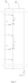
FIG. 1 is a schematic view of a structure of an electrode plate in the related art. -
FIG. 2 is a schematic view of a cutting path for cutting an electrode plate in the related art. -
FIG. 3 is a schematic view of a structure of an electrode plate according to an embodiment of the present disclosure. -
FIG. 4 is an enlarged view of a part P inFIG. 3 ; -
FIG. 5 is a schematic view of a cutting path and a laser path for cutting an electrode plate according to an embodiment of the present disclosure. - Reference numerals are as follows:
100, tab; 101, first region, 102, second region; 103, first edge; 104, second edge; 105, third edge; 105-1, first arc section; 105-2, second arc section; 200, electrode plate body; 100', tab region; 200', electrode plate body region. - Embodiments of the present disclosure will be described in detail below with reference to examples thereof as illustrated in accompanying drawings, throughout which same or similar elements, or elements having same or similar functions, are denoted by same or similar reference numerals. The embodiments described below with reference to the drawings are illustrative only, and are intended to explain, rather than limiting, the embodiments of the present disclosure.
- In one aspect of the present disclosure, an electrode plate is provided. According to the embodiment of the present disclosure, referring to
FIG. 3 andFIG. 4 , the electrode plate includes anelectrode plate body 200 and atab 100 located at least one end of theelectrode plate body 200 in a width direction (i.e. Y direction) of theelectrode plate body 200. Thetab 100 has afirst edge 103, asecond edge 104, and athird edge 105 that are connected in sequence. An end of thefirst edge 103 away from thesecond edge 104 is connected to theelectrode plate body 200. An end of thethird edge 105 away from thesecond edge 104 is connected to theelectrode plate body 200. Thethird edge 105 has a first arc section 105-1 and a second arc section 105-2. A connection position between the first arc section 105-1 and the second arc section 105-2 has a sharp corner. In the present disclosure, the sharp corner (i.e., an intersection point of cutting tracks) is formed at the connection position between the first arc section 105-1 and the second arc section 105-2 of thethird edge 105 of thetab 100, i.e., a cutting end point of a cutting cycle is positioned at a relatively middle region of the tab edge. Therefore, a problem that tab tearing and folding are easily caused by positioning the cutting end point at an end region of the tab edge is avoided, and the cutting stability of a laser in a high-speed cutting process can be satisfied. In this way, the integrity of the tab shape is ensured, and the maximum current allowed to pass through the tab is ensured. In addition, the charging and discharging efficiency of the lithium-ion battery is ensured. - The principle by which the electrode plate proposed in the present disclosure can achieve the above-mentioned advantageous effects will be described in detail below.
- The electrode plate in the related art is shown in
FIG. 1 . A smooth arc surface (i.e., thefirst edge 103 and the third edge 105) is provided at each of two sides of the tab in a length direction (i.e., X direction), and no sharp corner, i.e., no intersection point of cutting tracks, is formed at each of the two smooth arc surfaces. However, the tab structure shown inFIG. 1 cannot satisfy the cutting stability of the laser during high-speed cutting. In detail, a cutting method of an electrode plate structure shown inFIG. 1 , which may be referred toFIG. 2 , includes the following steps: step a) of providing an electrode plate substrate having an electrode plate body region 200' and a tab region 100' located at a side of the electrode plate body region 200' in a width direction (i.e., Y direction) of the electrode plate body region 200', and cutting, by using a laser, the electrode plate substrate from an end of the tab region 100' away from the electrode plate body region 200' towards the electrode plate body region 200' until top of the electrode plate body region 200', forming a first edge 103, which is shown in a path 1 inFIG. 2 ; step b) of cutting, by using the laser, the electrode plate substrate by a predetermined distance from a cutting end point of the step a) along a length direction (i.e., X direction) of the electrode plate substrate, which is shown in a path 2 inFIG. 2 ; step c) of cutting the electrode plate substrate by using the laser from a cutting end point of the step b) along an arc line and along a direction away from the electrode plate body region 200' until a top of the tab region 100', to form a third edge 105, which is shown in a path 3 inFIG. 2 . A cutting start point in the step a) and a cutting start point in the step c) are spaced apart by a predetermined distance in the length direction of the electrode plate substrate. At this time, a first scrap between adjacent tabs is cut off. The step a) to the step c) sequentially are repeated for a second time to form a first tab at the electrode plate substrate. Then, the step a) to the step c) sequentially are repeated for a third time to form a second tab at the electrode plate substrate, and the steps are repeated until all tabs at the electrode plate substrate are formed by cutting. However, in the cutting process of the tab, a moving direction of the electrode plate substrate and a moving direction between the scrap to be cut off under the action of the conveying belt are different, and a relative speed between the electrode plate substrate and the scrap to be cut off is very high. Therefore, in the step c), when the electrode plate substrate is cut to a position close to the top end of the electrode plate substrate, tearing easily occurs at the top end of the tab (i.e., an edge region of the tab) between the electrode plate substrate and the scrap to be cut in different directions, resulting in an incomplete tab shape formed by cutting, thus affecting the overcurrent ability and consistency of the tab and affecting the charge and discharge efficiency of the lithium-ion battery. In addition, in the step c), when the electrode plate substrate is cut to the position close to the top end of the electrode plate substrate, shaking or fluctuation of an apparatus will cause tearing at the top of the tab, resulting in the incomplete tab shape formed by cutting. - In order to solve the above problems, the present disclosure provides a new electrode plate. Referring to
FIG. 3 andFIG. 4 , the electrode plate structure can adapt to the cutting method of the present disclosure, and an intersection point of cutting tracks (i.e. sharp corner formed by the intersection of two arcs) is positioned at a connection position between the first arc section 105-1 and the second arc section 105-2 of thethird edge 105 of the tab. Positioning a cutting end point of a cutting cycle in a relatively middle region of the tab edge avoids a problem that positioning the cutting end point at an end region of the tab edge is easy to cause tab tearing. Therefore, the cutting stability of the laser in the high-speed cutting process can be met, thereby ensuring the integrity of the tab shape, ensuring the maximum current allowed to pass through the tab, and ensuring the charging and discharging efficiency of the lithium-ion battery. In an exemplary embodiment of the present disclosure, referring toFIG. 5 , the cutting method of the electrode plate includes: step S100 of providing an electrode plate substrate having an electrode plate body region 200' and a tab region 100' located at a side of the electrode plate body region 200' in a width direction of the electrode plate body region 200', and cutting, by using a laser, the electrode plate substrate from an end of the tab region 100' away from the electrode plate body region 200' towards the electrode plate body region 200' until top of the electrode plate body region 200', forming a first edge 103, which is shown in a path 1 inFIG. 5 ; step S200 of cutting, by using the laser, the electrode plate substrate by a predetermined length from a cutting end point in the step S 100 along a length direction of the electrode plate substrate, which is shown in a path 2 inFIG. 5 ; step S300 of cutting the electrode plate substrate by using the laser from a cutting end point in the step S200 along an arc line and along a direction away from the electrode plate body region 200' till a predetermined position, to form a second arc section 105-2, which is shown in a path 3 inFIG. 5 ; and step S400 of cutting the electrode plate substrate by using the laser from the end of the tab region 100' away from the electrode plate body region 200' towards a cutting end point in the step S300 along an arc line till intersecting with a cutting track in the step S300, to form a first arc section 105-1. A sharp corner is formed at a connection position between the first arc section 105-1 and the second arc section 105-2, which is shown in a path 4 inFIG. 5 . According to the present disclosure, the step c) in the related art is divided into two steps for cutting, i.e., the laser is turned off after cutting to the predetermined position in the step S300, then a laser is moved to the top end of tab region 100' to cut, and the electrode plate substrate is cut along an arc line and in the direction of the cutting end point in the step S300 till intersecting with the cutting track in the step S300. According to the cutting method, the cutting end point of a cycle is positioned at the relatively middle region of the tab edge, allowing the problem that the tab tearing is easily caused by arranging the cutting end point in the end area of the tab edge to be avoided. - According to some embodiments of the present disclosure, the
tab 100 has afirst region 101 and asecond region 102 located at a side of thefirst region 101 in a width direction of thefirst region 101. A side ofsecond region 102 away fromfirst region 101 is connected to the electrode plate body. Thesecond region 102 has an active material layer provided on at least part of a surface of the second region, thereby further improving the charge and discharge capacity of the battery as a whole. - In an embodiment of the present disclosure, the sharp corner formed at the connection position between the first arc section 105-1 and the second arc section 105-2 may be formed at the edge of the
first region 101, or may be formed at the edge of thesecond region 102, preferably formed at the edge of thesecond region 102. - According to some embodiments of the present disclosure, the sharp corner formed at the connection position between the first arc section 105-1 and the second arc section 105-2 is formed at the edge of the
second region 102. Referring toFIG. 3 andFIG. 4 , the first arc section 105-1 is formed at an edge of thefirst region 101 and extends to an edge of thesecond region 102. The second arc section 105-2 is formed at the edge of thesecond region 102. The first arc section 105-1 and the second arc section 105-2 intersect at the edge of thesecond region 102, i.e., the sharp corner is formed at the edge of thesecond region 102. Since thesecond region 102 has the surface provided with the active material layer, which has a thickness about 80 microns to 120 microns and a hardness of the surface of thesecond region 102 is relatively large, the tab tearing at the cutting end point is better avoided when the sharp corner (i.e., the cutting end point) is formed at thesecond region 102. - Further, as shown above, since the
second region 102 has the surface provided with the active material layer, which has a thickness about 80 microns to 120 microns and a hardness of the surface of thesecond region 102 is relatively large, the sharp corner (i.e., the cutting end point) is only required to be a certain distance from an end of thesecond region 102 close to the electrode plate body. As some specific examples, a width h2 of the second arc section 105-2 along the Y direction is greater than or equal to 2 mm. - According to still other embodiments of the present disclosure, the second arc section 105-2 is formed at an edge of the
second region 102 and extends to an edge of thefirst region 101. The first arc section 105-1 is formed at the edge of thefirst region 101. The first arc section 105-1 intersects with the second arc section 105-2 at the edge of thefirst region 101, and a sharp corner is formed at the edge of thefirst region 101. Further, a width h1 of the first arc section 105-1 in the Y direction is greater than or equal to 5 mm. Therefore, a distance between the sharp corner (i.e., the cutting end point) and the tab end is further ensured, i.e., the cutting end point of a cutting cycle is ensured to be positioned in the relatively middle region of the tab arc surface. In this way, the problem that the tab tearing is easily caused by positioning the cutting end point at the end area of the tab arc surface is further avoided. - According to some embodiments of the present disclosure, referring to
FIG. 4 , an angle between the first arc section 105-1 and the second arc section 105.2 is α, where 90 degrees <α <180 degrees (e.g., 100/110/120/130/140/150/160/170 degrees). That is, an angle between a tangent line passing through a final cutting point of the first arc section 105-1 and a tangent line passing through a final cutting point of the second arc section 105-2 is α, where 90 degrees <α <180 degrees. Therefore, this cutting arc is easier to achieve, i.e., the electrode plate of this structure is easier to realize in a laser preparation process. - In embodiments of the present disclosure, a width of the
first region 101 and a width of thesecond region 102 may be set according to different requirements of different types of batteries for tabs. As some specific examples, a ratio of a width of thefirst region 101 to a width of thesecond region 102 ranges from 5:1 to 5:2. - In the embodiment of the present disclosure, shapes of two vertex angles of the
first region 101 away from thesecond region 102 are not particularly limited, and can be set by a person skilled in the art based on actual requirements. For example, the top of thefirst region 101 can be cut at a right angle, an R angle, or an oblique angle. - In a second aspect of the present disclosure, a method of preparing the electrode plate of the above embodiment is provided. According to an embodiment of the present embodiment, with reference to the
FIG. 5 , the method includes the following steps. - Step S100: providing an electrode plate substrate having an electrode plate body region 200' and a tab region 100' located at a side of the electrode plate body region 200' in a width direction of the electrode plate body region 200', and cutting, by using a laser, the electrode plate substrate from an end of the tab region 100' away from the electrode plate body region 200' towards the electrode plate body region 200' until top of the electrode plate body region 200', forming a
first edge 103, which is shown in apath 1 inFIG. 5 . - Step S200: cutting, by using the laser, the electrode plate substrate by a predetermined length from a cutting end point in the
step S 100 along a length direction of the electrode plate substrate, which is shown in apath 2 inFIG. 5 . - In this step, the predetermined length is cut along the length of the electrode plate substrate based on a predesign.
- Step S300: cutting the electrode plate substrate by using the laser from a cutting end point in the step S200 along an arc line and along a direction away from the electrode plate body region 200' till a predetermined position, to form a second arc section 105-2, which is shown in a
path 3 inFIG. 5 . - In the step S300, the laser is turned off after cutting to the predetermined position, and then the laser is moved to the top end of tab region 100' to cut, where a moving track of the laser is shown as 3' in
FIG. 5 . The cutting end point in the step S300 may be located in a relatively middle region of the second region or a relatively middle region of the first region, thereby avoiding the problem that tab tearing is easily caused by positioning the cutting end point at the end region of the tab edge. - The predetermined position in the step S300 may be in the relatively middle region of the first region or in the relatively middle region of the second region.
- Step S400: cutting the electrode plate substrate by using the laser from the end of the tab region 100' away from the electrode plate body region 200' towards a cutting end point in the step S300 along an arc line till intersecting with a cutting track in the step S300, to form a first arc section 105-1. A sharp corner is formed at a connection position between the first arc section 105-1 and the second arc section 105-2, which is shown in a path 4 in
FIG. 5 . - In this step, a cutting start point in the S100 and a cutting start point in the S400 are spaced apart by a predetermined distance in the length direction of the electrode plate substrate, and the predetermined distance is a length of the scrap to be cut. In this case, a first scrap between adjacent tabs is cut off. The step S100 to the step S400 sequentially are repeated for a second time to form a first tab at the electrode plate substrate. Then, the S100 to the step S400 sequentially are repeated for a third time to form a second tab at the electrode plate substrate, and the step S100 to the step S400 are repeated until all tabs at the electrode plate substrate are formed by cutting. In the embodiments of the present disclosure, a size of the scrap to be cut off and a size of the tab formed by cut may be set based on actual requirements. It can be noted that a side of the tab formed by cutting away from the electrode plate body is the
second edge 104. - According to the present disclosure, the step c) in the related art is divided into two steps for cutting, namely, the laser is turned off after cutting to the predetermined position in the step S300, then the laser is moved to the end of tab region 100' away from the electrode plate body region 200' to cut, and the electrode plate substrate is cut along an arc line and along the direction of the cutting end point in the step S300 till intersecting with the cutting track in the step S300. According to the cutting method disclosed by the present disclosure, the cutting end point of a cycle is positioned at the relatively middle region of the tab edge, allowing the problem that the tab tearing is easily caused by positioning the cutting end point at the end region of the tab edge to be avoided. Therefore, the integrity of the tab shape is ensured, and the maximum current allowed to pass through the tab is ensured. In additon, the charging and discharging efficiency of the lithium-ion battery is ensured.
- At the same time, the existing cutting method further limits an operating speed of the apparatus. When the operating speed of the apparatus is greater than 100m/min, the tab tearing will be too serious that the cutting process cannot be carried out normally, and the laser track cannot match the operating speed of the apparatus. According to the present disclosure, a cutting end point of a cycle is positioned at the relatively middle region of the tab edge, allowing the problem that the tab tearing is easily caused by positioning the cutting end point at the end region of the tab edge to be avoided. Therefore, the cutting speed of the laser can be improved on the premise of avoiding the tab tearing, to allow the tab cutting in a high speed of the apparatus to be achieved. As some specific examples, a cutting speed of the laser in each of the
step 100, thestep 200, the step 300, and the step 400 ranges from 80m/min to 200m/min (e.g. 80/100/120/140/160/180/200m/min, etc.). - In addition, the cutting can be finished by adopting one laser machine, and compared with a scheme adopting two laser machines, the method reduces cost while ensuring the integrity of the tab shape in the tab cutting process.
- In some embodiments of the present disclosure, the tab region 100' has a width equal to a width of a tab obtained by cutting. Therefore, no waste edge in the width direction is generated in the cutting method.
- In the embodiments of the present disclosure, a plurality of tabs may be formed at the electrode plate substrate after the cutting is completed, and the plurality of tabs is overlapped after a winding lamination process.
- In a third aspect of the present disclosure, a battery is provided. According to the embodiment of the present disclosure, the battery includes the electrode plate of the above embodiment or the electrode plate formed by the method described in the above embodiment. Thus, the charging and discharging efficiency of the battery is ensured.
- In an exemplary embodiment of the present disclosure, a positive electrode plate of the battery may be the electrode plate described in the above embodiments, and a negative electrode plate of the battery may be the electrode plate described in the above embodiments. Both the positive electrode plate and the negative electrode plate of the battery may be the electrode plate described in the above embodiments.
- In a fourth aspect of the present disclosure, an electric apparatus is provided. According to the embodiment of the present disclosure, the electric apparatus includes the battery as described above. Therefore, the electric apparatus has all the advantages of the battery, which will not be described herein.
- In an exemplary embodiment of the present disclosure, the electric apparatus may be, but is not limited to, a mobile phone, a tablet, a notebook computer, an electric toy, an electric tool, a battery car, an electric automobile, a ship, a spacecraft, and the like. The electric toy may include a stationary or mobile electric toy, such as a game machine, an electric car toy, an electric ship toy, an electric airplane toy, and the like. The spacecraft may include an airplane, a rocket, a space shuttle, a spacecraft, and the like.
- In the description of this specification, description with reference to the terms "an embodiment", "some embodiments", "exemplary embodiments", "examples" "specific examples", or "some examples" etc., mean that specific features, structure, materials or characteristics described in conjunction with the embodiment or example are included in at least one embodiment or example of the present disclosure. In this specification, the schematic representations of the above terms do not necessarily refer to the same embodiment or example. Moreover, the described specific features, structures, materials, or characteristics may be combined in any one or more embodiments or examples in a suitable manner. In addition, different embodiments or examples and features of different embodiments or examples described in the specification may be combined by those skilled in the art without mutual contradiction.
- Although embodiments of the present disclosure have been shown and described above, it should be understood that the above embodiments are merely exemplary, and cannot be construed as limitations of the present disclosure. For those skilled in the art, changes, alternatives, and modifications can be made to the above embodiments without departing from the scope of the present disclosure.
Claims (11)
- An electrode plate, comprising:an electrode plate body; anda tab located at least one end of the electrode plate body in a width direction of the electrode plate body, the tab having a first edge, a second edge, and a third edge that are connected in sequence, wherein:an end of the first edge away from the second edge is connected to the electrode plate body;an end of the third edge away from the second edge is connected to the electrode plate body;the third edge has a first arc section and a second arc section, a connection position between the first arc section and the second arc section having a sharp corner.
- The electrode plate according to claim 1, wherein the tab has a first region and a second region located at a side of the first region in a width direction of the first region, a side of the second region away from the first region being connected to the electrode plate body, and the second region having an active material layer provided on at least part of a surface of the second region.
- The electrode plate according to claim 2, wherein:the first arc section is formed at an edge of the first region and extends to an edge of the second region;the second arc section is formed at the edge of the second region; andthe sharp corner is formed at the edge of the second region.
- The electrode plate according to claim 2, wherein:the second arc section is formed at an edge of the second region and extends to an edge of the first region;the first arc section is formed at the edge of the first region; andthe sharp corner is formed at the edge of the first region.
- The electrode plate according to any one of claims 1 to 4, wherein an angle between the first arc section and the second arc section is α, where 90 degrees <α <180 degrees.
- The electrode plate according to any one of claims 2 to 4, wherein a ratio of a width of the first region to a width of the second region ranges from 5:1 to 5:2.
- A method of preparing the electrode plate according to any one of claims 1 to 6, comprising:step 1 of providing an electrode plate substrate having an electrode plate body region and a tab region located at a side of the electrode plate body region in a width direction of the electrode plate body region, and cutting, by using a laser, the electrode plate substrate from an end of the tab region away from the electrode plate body region towards the electrode plate body region until top of the electrode plate body region, forming a first edge;step 2 of cutting, by using the laser, the electrode plate substrate by a predetermined distance from a cutting end point of the step 1 along a length direction of the electrode plate substrate;step 3 of cutting the electrode plate substrate by using the laser from a cutting end point of the step 2 along an arc line and along a direction away from the electrode plate body region till a predetermined position, to form a second arc section; andstep 4 of cutting the electrode plate substrate by using the laser from the end of the tab region away from the electrode plate body region towards a cutting end point of the step 3 along an arc line till intersecting with a cutting track of the step 3, to form a first arc section, a sharp corner being formed at a connection position between the first arc section and the second arc section,wherein a cutting start point in the step 1 and a cutting start point in the step 4 are spaced apart by a predetermined distance in the length direction of the electrode plate substrate.
- The method according to claim 7, wherein a cutting speed of the laser in each of the step 1, the step 2, the step 3, and the step 4 ranges from 80m/min to 200m/min.
- The method according to claim 7, wherein the tab region has a width equal to a width of a tab obtained by cutting.
- A battery, comprising:the electrode plate according to any one of claims 1 to 6; orthe electrode plate prepared by the method according to any one of claims 7 to 9.
- An electric apparatus, comprising the battery according to claim 10.
Applications Claiming Priority (1)
| Application Number | Priority Date | Filing Date | Title |
|---|---|---|---|
| CN202310768826.1A CN116646468A (en) | 2023-06-27 | 2023-06-27 | Pole piece, battery, electric equipment and pole piece manufacturing method |
Publications (1)
| Publication Number | Publication Date |
|---|---|
| EP4485676A1 true EP4485676A1 (en) | 2025-01-01 |
Family
ID=87615588
Family Applications (1)
| Application Number | Title | Priority Date | Filing Date |
|---|---|---|---|
| EP24172490.5A Pending EP4485676A1 (en) | 2023-06-27 | 2024-04-25 | Electrode plate and method of preparing electrode plate |
Country Status (4)
| Country | Link |
|---|---|
| US (1) | US20250007115A1 (en) |
| EP (1) | EP4485676A1 (en) |
| CN (1) | CN116646468A (en) |
| WO (1) | WO2025001160A1 (en) |
Families Citing this family (1)
| Publication number | Priority date | Publication date | Assignee | Title |
|---|---|---|---|---|
| CN116646468A (en) * | 2023-06-27 | 2023-08-25 | 厦门海辰储能科技股份有限公司 | Pole piece, battery, electric equipment and pole piece manufacturing method |
Citations (3)
| Publication number | Priority date | Publication date | Assignee | Title |
|---|---|---|---|---|
| CN114614211A (en) * | 2022-03-22 | 2022-06-10 | 东莞新能安科技有限公司 | Electrochemical device, battery module, and electronic device |
| CN115055836A (en) * | 2022-06-01 | 2022-09-16 | 深圳市海目星激光智能装备股份有限公司 | Pole piece segmentation cutting processing method, processing system and application thereof |
| CN219203436U (en) * | 2022-02-22 | 2023-06-16 | 上海兰钧新能源科技有限公司 | Battery pole piece, electrode assembly and secondary battery |
Family Cites Families (5)
| Publication number | Priority date | Publication date | Assignee | Title |
|---|---|---|---|---|
| JP5997911B2 (en) * | 2012-02-13 | 2016-09-28 | 日産自動車株式会社 | Laser cutting method and laser cutting apparatus |
| CN113798697B (en) * | 2021-09-29 | 2024-07-19 | 深圳市大族贝瑞装备有限公司 | Segmented laser cutting method |
| CN115041833A (en) * | 2022-06-01 | 2022-09-13 | 深圳市海目星激光智能装备股份有限公司 | A laser cutting device and battery production system |
| CN116140828A (en) * | 2023-01-30 | 2023-05-23 | 深圳市大族贝瑞装备有限公司 | Pole piece cutting method, cutting device and computer readable storage medium |
| CN116646468A (en) * | 2023-06-27 | 2023-08-25 | 厦门海辰储能科技股份有限公司 | Pole piece, battery, electric equipment and pole piece manufacturing method |
-
2023
- 2023-06-27 CN CN202310768826.1A patent/CN116646468A/en active Pending
-
2024
- 2024-02-05 WO PCT/CN2024/076149 patent/WO2025001160A1/en not_active Ceased
- 2024-04-25 EP EP24172490.5A patent/EP4485676A1/en active Pending
- 2024-05-19 US US18/668,223 patent/US20250007115A1/en active Pending
Patent Citations (3)
| Publication number | Priority date | Publication date | Assignee | Title |
|---|---|---|---|---|
| CN219203436U (en) * | 2022-02-22 | 2023-06-16 | 上海兰钧新能源科技有限公司 | Battery pole piece, electrode assembly and secondary battery |
| CN114614211A (en) * | 2022-03-22 | 2022-06-10 | 东莞新能安科技有限公司 | Electrochemical device, battery module, and electronic device |
| CN115055836A (en) * | 2022-06-01 | 2022-09-16 | 深圳市海目星激光智能装备股份有限公司 | Pole piece segmentation cutting processing method, processing system and application thereof |
Also Published As
| Publication number | Publication date |
|---|---|
| WO2025001160A1 (en) | 2025-01-02 |
| US20250007115A1 (en) | 2025-01-02 |
| CN116646468A (en) | 2023-08-25 |
Similar Documents
| Publication | Publication Date | Title |
|---|---|---|
| US20240396181A1 (en) | Tab plate and wound battery | |
| EP4343955A1 (en) | Tab plate and wound battery | |
| EP4485676A1 (en) | Electrode plate and method of preparing electrode plate | |
| US20240088449A1 (en) | Winding type electrode assembly, battery cell, battery and power consumption device | |
| KR102107742B1 (en) | Coating Device Reducing Thickness of Overlapping Region and Electrode Manufactured by Using the Same | |
| KR20210125281A (en) | The Apparatus And The Method For Manufacturing Electrode | |
| EP4439696A1 (en) | Electrode plate and preparation method therefor, and battery and electric apparatus | |
| EP4517946A1 (en) | Battery cell, battery, and electric device | |
| KR20210144311A (en) | The Electrode, The Secondary Battery, The Apparatus And The Method For Manufacturing Electrode | |
| JP2023521720A (en) | Electrode assembly including negative electrode sheet and negative electrode with improved lamination characteristics of electrode, and manufacturing method thereof | |
| JP2024539209A (en) | Electrode assembly, battery cell, battery, manufacturing method and manufacturing equipment for electrode assembly | |
| JP2019207872A (en) | Cell and laminated cell | |
| WO2025001334A1 (en) | Electrode sheet, battery cell and battery | |
| KR20220057309A (en) | Anode for secondary battery and method for manufacturing the same | |
| CN219203436U (en) | Battery pole piece, electrode assembly and secondary battery | |
| KR102781215B1 (en) | Method for Manufacturing Electrode Comprising Folding Portion and Electrode Sheet Having Folding Portion | |
| KR102852580B1 (en) | Secondary battery electrode | |
| JP4899723B2 (en) | Multilayer battery manufacturing method and manufacturing apparatus | |
| WO2023145223A1 (en) | Battery and production method for battery | |
| KR102848355B1 (en) | Electrode for secondary battery, secondary battery cell inclunding the same, and secondary battery cell manufacturing method for manufacturing the same | |
| CN223956570U (en) | Pole piece, secondary battery and electronic device | |
| CN224177531U (en) | A square battery cell | |
| US20260112654A1 (en) | Secondary battery, battery pack, and electronic device | |
| JP2023082776A (en) | Method for manufacturing secondary battery | |
| CN224036354U (en) | Electrode sheets, secondary batteries and electronic devices |
Legal Events
| Date | Code | Title | Description |
|---|---|---|---|
| PUAI | Public reference made under article 153(3) epc to a published international application that has entered the european phase |
Free format text: ORIGINAL CODE: 0009012 |
|
| STAA | Information on the status of an ep patent application or granted ep patent |
Free format text: STATUS: THE APPLICATION HAS BEEN PUBLISHED |
|
| AK | Designated contracting states |
Kind code of ref document: A1 Designated state(s): AL AT BE BG CH CY CZ DE DK EE ES FI FR GB GR HR HU IE IS IT LI LT LU LV MC ME MK MT NL NO PL PT RO RS SE SI SK SM TR |
|
| RAP1 | Party data changed (applicant data changed or rights of an application transferred) |
Owner name: HITHIUM TECH HK LIMITED |
|
| STAA | Information on the status of an ep patent application or granted ep patent |
Free format text: STATUS: REQUEST FOR EXAMINATION WAS MADE |
|
| STAA | Information on the status of an ep patent application or granted ep patent |
Free format text: STATUS: EXAMINATION IS IN PROGRESS |
|
| 17P | Request for examination filed |
Effective date: 20250630 |
|
| 17Q | First examination report despatched |
Effective date: 20250717 |