EP4485642A1 - Battery, battery pack, and vehicle - Google Patents
Battery, battery pack, and vehicle Download PDFInfo
- Publication number
- EP4485642A1 EP4485642A1 EP23803020.9A EP23803020A EP4485642A1 EP 4485642 A1 EP4485642 A1 EP 4485642A1 EP 23803020 A EP23803020 A EP 23803020A EP 4485642 A1 EP4485642 A1 EP 4485642A1
- Authority
- EP
- European Patent Office
- Prior art keywords
- lead
- battery
- positive
- negative
- sheet
- Prior art date
- Legal status (The legal status is an assumption and is not a legal conclusion. Google has not performed a legal analysis and makes no representation as to the accuracy of the status listed.)
- Pending
Links
Images









Classifications
-
- H—ELECTRICITY
- H01—ELECTRIC ELEMENTS
- H01M—PROCESSES OR MEANS, e.g. BATTERIES, FOR THE DIRECT CONVERSION OF CHEMICAL ENERGY INTO ELECTRICAL ENERGY
- H01M50/00—Constructional details or processes of manufacture of the non-active parts of electrochemical cells other than fuel cells, e.g. hybrid cells
- H01M50/50—Current conducting connections for cells or batteries
- H01M50/531—Electrode connections inside a battery casing
- H01M50/54—Connection of several leads or tabs of plate-like electrode stacks, e.g. electrode pole straps or bridges
-
- H—ELECTRICITY
- H01—ELECTRIC ELEMENTS
- H01M—PROCESSES OR MEANS, e.g. BATTERIES, FOR THE DIRECT CONVERSION OF CHEMICAL ENERGY INTO ELECTRICAL ENERGY
- H01M50/00—Constructional details or processes of manufacture of the non-active parts of electrochemical cells other than fuel cells, e.g. hybrid cells
- H01M50/10—Primary casings; Jackets or wrappings
- H01M50/172—Arrangements of electric connectors penetrating the casing
-
- H—ELECTRICITY
- H01—ELECTRIC ELEMENTS
- H01M—PROCESSES OR MEANS, e.g. BATTERIES, FOR THE DIRECT CONVERSION OF CHEMICAL ENERGY INTO ELECTRICAL ENERGY
- H01M50/00—Constructional details or processes of manufacture of the non-active parts of electrochemical cells other than fuel cells, e.g. hybrid cells
- H01M50/20—Mountings; Secondary casings or frames; Racks, modules or packs; Suspension devices; Shock absorbers; Transport or carrying devices; Holders
- H01M50/249—Mountings; Secondary casings or frames; Racks, modules or packs; Suspension devices; Shock absorbers; Transport or carrying devices; Holders specially adapted for aircraft or vehicles, e.g. cars or trains
-
- H—ELECTRICITY
- H01—ELECTRIC ELEMENTS
- H01M—PROCESSES OR MEANS, e.g. BATTERIES, FOR THE DIRECT CONVERSION OF CHEMICAL ENERGY INTO ELECTRICAL ENERGY
- H01M50/00—Constructional details or processes of manufacture of the non-active parts of electrochemical cells other than fuel cells, e.g. hybrid cells
- H01M50/10—Primary casings; Jackets or wrappings
- H01M50/102—Primary casings; Jackets or wrappings characterised by their shape or physical structure
- H01M50/103—Primary casings; Jackets or wrappings characterised by their shape or physical structure prismatic or rectangular
-
- H—ELECTRICITY
- H01—ELECTRIC ELEMENTS
- H01M—PROCESSES OR MEANS, e.g. BATTERIES, FOR THE DIRECT CONVERSION OF CHEMICAL ENERGY INTO ELECTRICAL ENERGY
- H01M50/00—Constructional details or processes of manufacture of the non-active parts of electrochemical cells other than fuel cells, e.g. hybrid cells
- H01M50/10—Primary casings; Jackets or wrappings
- H01M50/183—Sealing members
- H01M50/184—Sealing members characterised by their shape or structure
-
- H—ELECTRICITY
- H01—ELECTRIC ELEMENTS
- H01M—PROCESSES OR MEANS, e.g. BATTERIES, FOR THE DIRECT CONVERSION OF CHEMICAL ENERGY INTO ELECTRICAL ENERGY
- H01M50/00—Constructional details or processes of manufacture of the non-active parts of electrochemical cells other than fuel cells, e.g. hybrid cells
- H01M50/20—Mountings; Secondary casings or frames; Racks, modules or packs; Suspension devices; Shock absorbers; Transport or carrying devices; Holders
- H01M50/204—Racks, modules or packs for multiple batteries or multiple cells
- H01M50/207—Racks, modules or packs for multiple batteries or multiple cells characterised by their shape
- H01M50/209—Racks, modules or packs for multiple batteries or multiple cells characterised by their shape adapted for prismatic or rectangular cells
-
- H—ELECTRICITY
- H01—ELECTRIC ELEMENTS
- H01M—PROCESSES OR MEANS, e.g. BATTERIES, FOR THE DIRECT CONVERSION OF CHEMICAL ENERGY INTO ELECTRICAL ENERGY
- H01M50/00—Constructional details or processes of manufacture of the non-active parts of electrochemical cells other than fuel cells, e.g. hybrid cells
- H01M50/50—Current conducting connections for cells or batteries
- H01M50/528—Fixed electrical connections, i.e. not intended for disconnection
-
- H—ELECTRICITY
- H01—ELECTRIC ELEMENTS
- H01M—PROCESSES OR MEANS, e.g. BATTERIES, FOR THE DIRECT CONVERSION OF CHEMICAL ENERGY INTO ELECTRICAL ENERGY
- H01M50/00—Constructional details or processes of manufacture of the non-active parts of electrochemical cells other than fuel cells, e.g. hybrid cells
- H01M50/50—Current conducting connections for cells or batteries
- H01M50/531—Electrode connections inside a battery casing
- H01M50/533—Electrode connections inside a battery casing characterised by the shape of the leads or tabs
-
- H—ELECTRICITY
- H01—ELECTRIC ELEMENTS
- H01M—PROCESSES OR MEANS, e.g. BATTERIES, FOR THE DIRECT CONVERSION OF CHEMICAL ENERGY INTO ELECTRICAL ENERGY
- H01M50/00—Constructional details or processes of manufacture of the non-active parts of electrochemical cells other than fuel cells, e.g. hybrid cells
- H01M50/50—Current conducting connections for cells or batteries
- H01M50/531—Electrode connections inside a battery casing
- H01M50/534—Electrode connections inside a battery casing characterised by the material of the leads or tabs
-
- H—ELECTRICITY
- H01—ELECTRIC ELEMENTS
- H01M—PROCESSES OR MEANS, e.g. BATTERIES, FOR THE DIRECT CONVERSION OF CHEMICAL ENERGY INTO ELECTRICAL ENERGY
- H01M50/00—Constructional details or processes of manufacture of the non-active parts of electrochemical cells other than fuel cells, e.g. hybrid cells
- H01M50/50—Current conducting connections for cells or batteries
- H01M50/543—Terminals
- H01M50/547—Terminals characterised by the disposition of the terminals on the cells
- H01M50/548—Terminals characterised by the disposition of the terminals on the cells on opposite sides of the cell
-
- H—ELECTRICITY
- H01—ELECTRIC ELEMENTS
- H01M—PROCESSES OR MEANS, e.g. BATTERIES, FOR THE DIRECT CONVERSION OF CHEMICAL ENERGY INTO ELECTRICAL ENERGY
- H01M50/00—Constructional details or processes of manufacture of the non-active parts of electrochemical cells other than fuel cells, e.g. hybrid cells
- H01M50/50—Current conducting connections for cells or batteries
- H01M50/543—Terminals
- H01M50/552—Terminals characterised by their shape
-
- H—ELECTRICITY
- H01—ELECTRIC ELEMENTS
- H01M—PROCESSES OR MEANS, e.g. BATTERIES, FOR THE DIRECT CONVERSION OF CHEMICAL ENERGY INTO ELECTRICAL ENERGY
- H01M50/00—Constructional details or processes of manufacture of the non-active parts of electrochemical cells other than fuel cells, e.g. hybrid cells
- H01M50/50—Current conducting connections for cells or batteries
- H01M50/543—Terminals
- H01M50/552—Terminals characterised by their shape
- H01M50/553—Terminals adapted for prismatic, pouch or rectangular cells
-
- H—ELECTRICITY
- H01—ELECTRIC ELEMENTS
- H01M—PROCESSES OR MEANS, e.g. BATTERIES, FOR THE DIRECT CONVERSION OF CHEMICAL ENERGY INTO ELECTRICAL ENERGY
- H01M50/00—Constructional details or processes of manufacture of the non-active parts of electrochemical cells other than fuel cells, e.g. hybrid cells
- H01M50/50—Current conducting connections for cells or batteries
- H01M50/543—Terminals
- H01M50/562—Terminals characterised by the material
-
- H—ELECTRICITY
- H01—ELECTRIC ELEMENTS
- H01M—PROCESSES OR MEANS, e.g. BATTERIES, FOR THE DIRECT CONVERSION OF CHEMICAL ENERGY INTO ELECTRICAL ENERGY
- H01M50/00—Constructional details or processes of manufacture of the non-active parts of electrochemical cells other than fuel cells, e.g. hybrid cells
- H01M50/50—Current conducting connections for cells or batteries
- H01M50/572—Means for preventing undesired use or discharge
- H01M50/584—Means for preventing undesired use or discharge for preventing incorrect connections inside or outside the batteries
- H01M50/586—Means for preventing undesired use or discharge for preventing incorrect connections inside or outside the batteries inside the batteries, e.g. incorrect connections of electrodes
-
- H—ELECTRICITY
- H01—ELECTRIC ELEMENTS
- H01M—PROCESSES OR MEANS, e.g. BATTERIES, FOR THE DIRECT CONVERSION OF CHEMICAL ENERGY INTO ELECTRICAL ENERGY
- H01M50/00—Constructional details or processes of manufacture of the non-active parts of electrochemical cells other than fuel cells, e.g. hybrid cells
- H01M50/50—Current conducting connections for cells or batteries
- H01M50/572—Means for preventing undesired use or discharge
- H01M50/584—Means for preventing undesired use or discharge for preventing incorrect connections inside or outside the batteries
- H01M50/59—Means for preventing undesired use or discharge for preventing incorrect connections inside or outside the batteries characterised by the protection means
- H01M50/593—Spacers; Insulating plates
-
- H—ELECTRICITY
- H01—ELECTRIC ELEMENTS
- H01M—PROCESSES OR MEANS, e.g. BATTERIES, FOR THE DIRECT CONVERSION OF CHEMICAL ENERGY INTO ELECTRICAL ENERGY
- H01M2220/00—Batteries for particular applications
- H01M2220/20—Batteries in motive systems, e.g. vehicle, ship, plane
-
- Y—GENERAL TAGGING OF NEW TECHNOLOGICAL DEVELOPMENTS; GENERAL TAGGING OF CROSS-SECTIONAL TECHNOLOGIES SPANNING OVER SEVERAL SECTIONS OF THE IPC; TECHNICAL SUBJECTS COVERED BY FORMER USPC CROSS-REFERENCE ART COLLECTIONS [XRACs] AND DIGESTS
- Y02—TECHNOLOGIES OR APPLICATIONS FOR MITIGATION OR ADAPTATION AGAINST CLIMATE CHANGE
- Y02E—REDUCTION OF GREENHOUSE GAS [GHG] EMISSIONS, RELATED TO ENERGY GENERATION, TRANSMISSION OR DISTRIBUTION
- Y02E60/00—Enabling technologies; Technologies with a potential or indirect contribution to GHG emissions mitigation
- Y02E60/10—Energy storage using batteries
Definitions
- the present disclosure relates to the field of battery technologies, and specifically to a battery, a battery pack, and a vehicle.
- a lead-out sheet is arranged in a battery housing and is connected between a tab of an electrode core and a conductive post, so that a current flows inside and outside the battery.
- a lead-out sheet has a single size. Either a cross-sectional area of the lead-out sheet is too large, resulting in a waste of resources, or a cross-sectional area of the lead-out sheet is too small, resulting in a heating problem, and further causing a thermal security problem of the battery.
- an objective of the present disclosure is to provide a battery with a strong current carrying capability, to ensure that during use, a temperature does not rise excessively due to a small current carrying area, and does not exceed an operating temperature range of the battery, to avoid a thermal security problem of the battery.
- the present disclosure further provides a battery pack having the battery described above.
- the present disclosure further provides a vehicle having the battery pack described above.
- the battery according to the present disclosure includes a battery housing, an electrode core, lead-out sheets, and conductive posts.
- the electrode core and the lead-out sheets are all arranged in the battery housing, the lead-out sheets are connected to the electrode core, and the conductive posts pass through the battery housing, so that the conductive posts are connected to the lead-out sheets.
- a relationship between a cross-sectional area s lead of the lead-out sheets and a capacity C of the battery is C/s lead ⁇ 15.
- a unit of s lead is mm 2
- a unit of C is Ah.
- the relationship between the cross-sectional area s lead of the lead-out sheets and the capacity C of the battery is configured as C/s lead ⁇ 8. This ensures a current carrying capability of the lead-out sheet, and ensures that a temperature of the lead-out sheet does not rise excessively due to a small current carrying area during use of the battery, so that internal temperature distribution of the battery is not affected, an internal temperature in the battery does not exceed an operating temperature range of the battery, and a thermal security problem of the battery is not caused.
- the relationship between the cross-sectional area s lead of the lead-out sheets and the capacity C of the battery is 2 ⁇ C/s lead ⁇ 15.
- the relationship between the cross-sectional area s lead of the lead-out sheets and the capacity C of the battery is 2 ⁇ C/s lead ⁇ 15.
- the lead-out sheets include a positive lead-out sheet and a negative lead-out sheet.
- the conductive posts include a positive conductive post and a negative conductive post.
- the positive lead-out sheet passes through the battery housing and is connected to the positive conductive post, and the negative lead-out sheet passes through the battery housing and is connected to the negative conductive post.
- a relationship between a cross-sectional area s positive lead of the positive lead-out sheet and the capacity C of the battery is 5 ⁇ C/s positive lead ⁇ 12
- a relationship between a cross-sectional area s negative lead of the negative lead-out sheet and the capacity C of the battery is 6 ⁇ C/s negative lead ⁇ 15.
- a cross section of the positive lead-out sheet and a cross section of the negative lead-out sheet each are a surface orthogonal to a current flow direction, units of s positive lead and s negative lead are mm 2 , and a unit of C is Ah.
- the cross-sectional area of the positive lead-out sheet ranges from 14 mm 2 to 150 mm 2
- the cross-sectional area of the negative lead-out sheet ranges from 10 mm 2 to 130 mm 2
- the capacity C of the battery ranges from 30 Ah to 400 Ah.
- the positive lead-out sheet is an aluminum sheet
- the negative lead-out sheet is a copper sheet.
- the positive lead-out sheet and the negative lead-out sheet each include a first connection sheet and a second connection sheet that are connected.
- the second connection sheet of the positive lead-out sheet is connected to a positive tab of the electrode core
- the first connection sheet of the positive lead-out sheet is connected to the positive conductive post
- the second connection sheet of the negative lead-out sheet is connected to a negative tab of the electrode core
- the first connection sheet of the negative lead-out sheet is connected to the negative conductive post.
- a size of the first connection sheet in a length direction of the battery ranges from 0.8 mm to 2 mm.
- a size of the first connection sheet in the length direction of the battery ranges from 0.6 mm to 2 mm.
- the battery housing includes a first plate piece and a second plate piece that are opposite to each other in the length direction of the battery.
- the first connection sheet of the positive lead-out sheet and the first connection sheet of the negative lead-out sheet each are parallel to the first plate piece and the second plate piece.
- the battery housing further includes a third plate piece and a fourth plate piece that are opposite to each other in a width direction of the battery, and a fifth plate piece and a sixth plate piece that are opposite to each other in a thickness direction of the battery.
- the second connection sheet of the positive lead-out sheet and the second connection sheet of the negative lead-out sheet each are parallel to the fifth plate piece and the sixth plate piece.
- the first plate piece, the second plate piece, the third plate piece, the fourth plate piece, and the fifth plate piece are configured as a lower housing with one side open, and the sixth plate piece is fixedly connected to the lower housing to block an open end of the lower housing.
- the battery further includes a first insulating spacer arranged in the battery housing. At least a part of the first insulating spacer is located between the positive lead-out sheet and the first plate piece, and the positive conductive post passes through the first insulating spacer and is connected to the positive lead-out sheet.
- the battery further includes a second insulating spacer arranged in the battery housing. At least a part of the second insulating spacer is located between the negative lead-out sheet and the second plate piece, and the negative conductive post passes through the second insulating spacer and is connected to the negative lead-out sheet.
- a relationship between a cross-sectional area s1 of the positive conductive post and the capacity C of the battery is 6/5 ⁇ C/s1 ⁇ 16/3
- a relationship between a cross-sectional area s2 of the negative conductive post and the capacity C of the battery is 6/5 ⁇ C/s2 ⁇ 8, where units of s1 and s2 are both mm 2 .
- the cross-sectional area s1 of the positive conductive post and the cross-sectional area s2 of the negative conductive post range from 12 mm 2 to 315 mm 2
- the capacity C of the battery ranges from 30 Ah to 400 Ah.
- the positive conductive post is an aluminum post
- the negative conductive post is a copper post
- a battery pack according to the present disclosure includes the battery described above.
- a vehicle according to the present disclosure includes the battery described above or the battery pack described above.
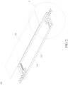
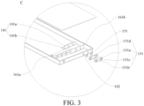
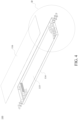
- a battery 100 according to the embodiments of the present disclosure is described below with reference to FIG. 1 to FIG. 36 .
- the battery includes a battery housing 110, an electrode core 120, and conductive posts.
- the electrode core 120 is arranged in the battery housing 110, and the conductive post passes through the battery housing 110, so that an inner end of the conductive post is connected to the electrode core 120, and an outer end of the conductive post extends out of the battery housing 110. Specifically, the inner end of the conductive post is connected to a tab of the electrode core 120.
- a cross-sectional area of the conductive post is s
- a capacity of the battery is C
- a relationship between s and C is C/s ⁇ 8, where a unit of s is mm 2 , and a unit of C is Ah.
- a size of a cross-sectional area of the conductive post represents a current carrying capability of the conductive post.
- a larger cross-sectional area of the conductive post represents a stronger current carrying capability of the conductive post.
- a smallest cross-sectional area on the conductive post determines the current carrying capability of the conductive post.
- a cross section of the conductive post is a surface orthogonal to a current flow direction. If the conductive post is a cylinder, and the current flow direction of the conductive post is an axial direction of the conductive post, the cross section of the conductive post is a radial cross section, and a shape is circular.
- a cross-sectional area of the conductive post may be understood as an area of a smallest cross section on the conductive post.
- C/s ⁇ 8 This ensures a current carrying capability of the conductive post of the battery 100, and ensures that during use of the battery 100, a temperature does not rise excessively due to a small current carrying area, and does not exceed an operating temperature range of the battery 100, to avoid a thermal security problem of the battery 100.
- the relationship between the cross-sectional area s of the conductive post and the capacity C of the battery is 6/5 ⁇ C/s ⁇ 8.
- the inventors find that a ratio of the capacity C of the battery to the cross-sectional area s of the conductive post is not necessarily better when smaller. A ratio that is too small may cause an excessively large size of the conductive post, resulting in a redundant design.
- the conductive posts include a positive conductive post 131 and a negative conductive post 132.
- a relationship between a cross-sectional area s1 of the positive conductive post 131 and the capacity C of the battery is 6/5 ⁇ C/s1 ⁇ 16/3
- a relationship between a cross-sectional area s2 of the negative conductive post 132 and the capacity C of the battery is 6/5 ⁇ C/s2 ⁇ 8, where units of s1 and s2 are both mm 2 .
- the cross-sectional area s1 of the positive conductive post 131 is a sum of cross-sectional areas of the multiple positive posts.
- a cross-sectional area of the positive post may be understood as an area of a smallest cross section on the positive post.
- the negative conductive post 132 includes multiple negative posts that pass through the battery housing 110 and are connected to negative tabs of the electrode core 120
- the cross-sectional area s2 of the negative conductive post 132 is a sum of cross-sectional areas of the multiple negative posts.
- a cross-sectional area of the negative post may be understood as an area of a smallest cross section on the negative post.
- the relationship between the cross-sectional area s1 of the positive conductive post 131 and the capacity C of the battery is 8/3 ⁇ C/s1 ⁇ 16/3
- the relationship between the cross-sectional area s2 of the negative conductive post 132 and the capacity C of the battery is 3 ⁇ C/s2 ⁇ 8.
- the positive conductive post 131 of the battery 100 may be made of aluminum materials
- the negative conductive post 132 may be made of copper materials
- conductivities of the aluminum materials and the copper materials are different. Copper has a stronger current carrying capability than aluminum when cross-sectional areas are the same. Therefore, to ensure same current carrying capabilities of the positive conductive post 131 and the negative conductive post 132, the cross-sectional area of the negative conductive post 132 made of copper may be smaller.
- the cross-sectional area s1 of the positive conductive post and the cross-sectional area s2 of the negative conductive post range from 12 mm 2 to 315 mm 2
- the capacity C of the battery ranges from 30 Ah to 400 Ah.
- FIG. 21 is a temperature rise curve diagram of the positive conductive post 131 and the negative conductive post 132 in the comparative example and Embodiment 1.
- FIG. 22 is a temperature rise curve diagram of the positive conductive post 131 and the negative conductive post 132 in the comparative example and Embodiment 2.
- FIG. 23 is a temperature rise curve diagram of the positive conductive post 131 and the negative conductive post 132 in the comparative example and Embodiment 3.
- FIG. 24 is a temperature rise curve diagram of the positive conductive post 131 and the negative conductive post 132 in the comparative example and Embodiment 4.
- FIG. 25 is a temperature rise curve diagram of the positive conductive post 131 and the negative conductive post 132 in the comparative example and Embodiment 5.
- FIG. 22 is a temperature rise curve diagram of the positive conductive post 131 and the negative conductive post 132 in the comparative example and Embodiment 2.
- FIG. 23 is a temperature rise curve diagram of the positive conductive post 131 and the
- FIG. 26 is a temperature rise curve diagram of the positive conductive post 131 and the negative conductive post 132 in the comparative example and Embodiment 6.
- FIG. 27 is a temperature rise curve diagram of the positive conductive post 131 and the negative conductive post 132 in the comparative example and Embodiment 7.
- FIG. 28 is a temperature rise curve diagram of the positive conductive post 131 and the negative conductive post 132 in the comparative example and Embodiment 8.
- the positive conductive post 131 includes a first positive conductive post 131a, a second positive conductive post 131b, and a first connection member 131c. Both the first positive conductive post 131a and the second positive conductive post 131b pass through the battery housing 110 and are connected to positive tabs of the electrode core 120.
- the first connection member 131c is arranged outside the battery housing 110 and is electrically connected to the first positive conductive post 131a and the second positive conductive post 131b.
- the cross-sectional area s1 of the positive conductive post 131 is a sum of a cross-sectional area of the first positive conductive post 131a and a cross-sectional area of the second positive conductive post 131b.
- the negative conductive post 132 includes a first negative conductive post 132a, a second negative conductive post 132b, and a second connection member 132c. Both the first negative conductive post 132a and the second negative conductive post 132b pass through the battery housing 110 and are connected to negative tabs of the electrode core 120.
- the second connection member 132c is arranged outside the battery housing 110 and is electrically connected to the first negative conductive post 132a and the second negative conductive post 132b.
- the cross-sectional area s2 of the negative conductive post 132 is a sum of a cross-sectional area of the first negative conductive post 132a and a cross-sectional area of the second negative conductive post 132b.
- the first connection member 131c is connected between an outer end of the first positive conductive post 131a and an outer end of the second positive conductive post 131b, so that a contact area between the first positive conductive post 131a and the second positive conductive post 131b is increased, and the positive conductive post 131 can be connected to the outside more easily.
- the second connection member 132c is connected between an outer end of the first negative conductive post 132a and an outer end of the second negative conductive post 132b, so that a contact area between the first negative conductive post 132a and the second negative conductive post 132b is increased, and the negative conductive post 132 can be connected to the outside more easily.
- cross sections of the first positive conductive post 131a and the second positive conductive post 131b are circular or obround-shaped, and cross sections of the first negative conductive post 132a and the second negative conductive post 132b are circular or obround-shaped. If a size of the battery housing 110 in a thickness direction is large, the first positive conductive post 131a, the second positive conductive post 131b, the first negative conductive post 132a, and the second negative conductive post 132b with a circular cross section may be used.
- the first positive conductive post 131a, the second positive conductive post 131b, the first negative conductive post 132a, and the second negative conductive post 132b with an obround-shaped cross section may be used. This can ensure that the first positive conductive post 131a, the second positive conductive post 131b, the first negative conductive post 132a, and the second negative conductive post 132b do not exceed the size of the battery housing 110 in the thickness direction on the premise that the positive conductive post 131 and the negative conductive post 132 have sufficient current carrying capabilities.
- the battery housing 110 includes a first plate piece 111 and a second plate piece 112 that are opposite to each other in a length direction of the battery 100, a third plate piece 113 and a fourth plate piece 114 that are opposite to each other in a width direction of the battery 100, and a fifth plate piece 115 and a sixth plate piece 116 that are opposite to each other in the thickness direction of the battery 100.
- a size of the battery 100 in the length direction is greater than a size of the battery 100 in the width direction
- the size of the battery 100 in the width direction is greater than the size of the battery 100 in the thickness direction.
- the first plate piece 111 and the second plate piece 112 are respectively connected to one end and the other end on a same side of the third plate piece 113 and the fourth plate piece 114 in the length direction of the battery 100.
- the first plate piece 111 is connected to one end on the same side of the third plate piece 113 and the fourth plate piece 114 in the length direction of the battery 100
- the second plate piece 112 is connected to the other end on the same side of the third plate piece 113 and the fourth plate piece 114 in the length direction of the battery 100.
- the fifth plate piece 115 and the sixth plate piece 116 are respectively connected to one end and the other end on a same side of the third plate piece 113 and the fourth plate piece 114 in the thickness direction of the battery 100.
- the fifth plate piece 115 is connected to one end on the same side of the third plate piece 113 and the fourth plate piece 114 in the thickness direction of the battery 100
- the sixth plate piece 116 is connected to the other end on the same side of the third plate piece 113 and the fourth plate piece 114 in the thickness direction of the battery 100.
- the positive conductive post 131 is arranged on the first plate piece 111, the negative conductive post 132 is arranged on the second plate piece 112, a first insulating plate 131d is arranged between the first plate piece 111 and the first connection member 131c, and a second insulating plate 132d is arranged between the second plate piece 112 and the second connection member 132c.
- This can effectively avoid an electrical connection between the first connection member 131c and the battery housing 110, and an electrical connection between the second connection member 132c and the battery housing 110.
- first via through which the first positive conductive post 131a passes and a second via through which the second positive conductive post 131b passes are provided on the first plate piece 111
- a third via through which the first negative conductive post 132a passes and a fourth via through which the second negative conductive post 132b passes are provided on the second plate piece 112.
- a positive lead-out sheet 141 and a negative lead-out sheet 142 are further arranged in the battery housing 110.
- the positive lead-out sheet 141 may be connected to a positive tab of the electrode core 120, in addition, the positive lead-out sheet 141 is further connected to the positive conductive post 131, the negative lead-out sheet 142 may be connected to a negative tab of the electrode core 120, and in addition, the negative lead-out sheet 142 is further connected to the negative conductive post 132.
- a first sealing ring 151 is sleeved on the positive conductive post 131, and the first sealing ring 151 is sandwiched between the positive lead-out sheet 141 and the first plate piece 111.
- a second sealing ring 152 is sleeved on the negative conductive post 132, and the second sealing ring 152 is sandwiched between the negative lead-out sheet 142 and the second plate piece 112.
- the positive conductive post 131 is limited by the first sealing ring 151, so that the positive conductive post 131 does not contact an inner wall of a via that is on the first plate piece 111 and through which the positive conductive post 131 passes, and the negative conductive post 132 is limited by the second sealing ring 152, so that the negative conductive post 132 does not contact an inner wall of a via that is on the second plate piece 112 and through which the negative conductive post 132 passes.
- a first insulating spacer 161 is further arranged between the positive lead-out sheet 141 and the first plate piece 111.
- the positive conductive post 131 passes through the first insulating spacer 161 and is connected to the positive lead-out sheet 141.
- the first insulating spacer 161 is an insulating member. The first insulating spacer 161 can avoid contact between the positive lead-out sheet 141 and the battery housing 110, to improve security performance of the battery 100.
- a second insulating spacer 162 is further arranged between the negative lead-out sheet 142 and the second plate piece 112.
- the negative conductive post 132 passes through the second insulating spacer 162 and is connected to the negative lead-out sheet 142.
- the second insulating spacer 162 is an insulating member. The second insulating spacer 162 can avoid contact between the negative lead-out sheet 142 and the battery housing 110, to improve security performance of the battery 100.
- a first step piece that is matched with an inner end of the first sealing ring 151 is arranged on an outer surface of the first insulating spacer 161, and the first step piece may limit movement of the first sealing ring 151 and the positive conductive post 131, to avoid direct contact between the positive conductive post 131 and the battery housing 110.
- a second step piece that is matched with an inner end of the second sealing ring 152 is arranged on an outer surface of the second insulating spacer 162, and the second step piece may limit movement of the second sealing ring 152 and the negative conductive post 132, to avoid direct contact between the negative conductive post 132 and the battery housing 110.
- a part of an inner end of the positive conductive post 131 is matched with a step piece on the first insulating spacer 161, another part of the positive conductive post 131 abuts against the positive lead-out sheet 141, a part of an inner end of the negative conductive post 132 is matched with a step piece on the second insulating spacer 162, and another part of the negative conductive post 132 abuts against the negative lead-out sheet 142.
- sizes of a first insulating piece vertical plate 161b and a second insulating piece vertical plate 162b each range from 0.3 mm to 1.5 mm in a length direction of the battery housing.
- a thickness is less than 0.3 mm
- welding heat may melt a spacer when a tab and a lead-out sheet are welded, resulting in insufficient insulation.
- a thickness is greater than 1.5 mm, too much space of the electrode core 120 is occupied, resulting in reduced space utilization, and a design capacity of the battery 100 is affected. Therefore, after multiple experiments and adjustments by the inventors of the present disclosure, sizes of both the first insulating piece vertical plate 161b and the second insulating piece vertical plate 162b are selected as 0.3 mm to 1.5 mm in the length direction of the battery housing 110.
- the first insulating spacer 161 includes a first support piece 161a and a first insulating piece connected to the first support piece 161a.
- An inner end and an outer end of the first support piece 161a respectively abut against the electrode core 120 and the first plate piece 111 of the battery 100, and the first insulating piece is matched with the positive lead-out sheet 141 and is arranged between the positive lead-out sheet 141 and the battery housing 110.
- the second insulating spacer 162 includes a second support piece 162a and a second insulating piece connected to the second support piece 162a.
- An inner end and an outer end of the second support piece 162a respectively abut against an end of the electrode core 120 and the second plate piece 112, and the second insulating piece is matched with the negative lead-out sheet 142 and is arranged between the negative lead-out sheet 142 and the battery housing 110.
- the first insulating piece includes the first insulating piece vertical plate 161b and a first insulating piece horizontal plate 161c.
- the first insulating piece vertical plate 161b is arranged between a positive first connection sheet 141a and the first plate piece 111
- the first insulating piece horizontal plate 161c is arranged between a positive second connection sheet 141b and a side plate of the battery housing 110 in the thickness direction.
- the second insulating piece includes the second insulating piece vertical plate 162b and a second insulating piece horizontal plate 162c.
- the second insulating piece vertical plate 162b is arranged between a negative first connection sheet 142a and the second plate piece 112, and the second insulating piece horizontal plate 162c is arranged between a negative second connection sheet 142b and a side plate of the battery housing 110 in the thickness direction.
- the first plate piece 111, the second plate piece 112, the third plate piece 113, the fourth plate piece 114, and the fifth plate piece 115 are configured as a lower housing with one side open, and the sixth plate piece 116 is fixedly connected to the lower housing to block an open end of the lower housing. Therefore, the electrode core 120 enters the inside of the battery housing 110 not through a narrow channel, but through a very wide open end, to greatly reduce installation costs and save installation time.
- the first insulating piece horizontal plate 161c is arranged between the positive second connection sheet 141b and the fifth plate piece 115
- the second insulating piece horizontal plate 162c is arranged between the negative second connection sheet 142b and the fifth plate piece 115.
- a size of the first support piece 161a in the length direction of the battery housing 110 is greater than a size of the first insulating piece vertical plate 161b in the length direction of the battery housing 110, and a size of the second support piece 162a in the length direction of the battery housing 110 is greater than a size of the second insulating piece vertical plate 162b in the length direction of the battery housing 110. Therefore, the first support piece 161a and the second support piece 162a may firmly clamp the electrode core 120 inside the battery housing 110, to prevent the electrode core 120 from moving inside the battery housing 110.
- an outer surface of the positive conductive post 131 extends out of the battery housing and has a distance of 2 mm to 5 mm from an outer surface of the first plate piece 111
- an outer surface of the negative conductive post 132 extends out of the battery housing and has a distance of 2 mm to 5 mm from an outer surface of the second plate piece 112. Therefore, it is ensured that the positive conductive post 131 and the negative conductive post 132 can have enough protrusion to connect to an external electrical component.
- space of the battery 100 in the length direction is not excessively occupied, to ensure that the battery 100 has enough capacity.
- the electrode core 120 and the lead-out sheet are both arranged in the battery housing 110, and the lead-out sheet and the electrode core 120 are connected.
- the lead-out sheet is connected to a tab of the electrode core 120
- the conductive post passes through the battery housing 110
- an inner end of the conductive post is connected to the lead-out sheet
- an outer end of the conductive post protrudes from the battery housing 110, so that the conductive post can charge and discharge the electrode core 120.
- a relationship between a cross-sectional area s lead of the lead-out sheet and a capacity C of the battery is C/s lead ⁇ 15. It should be noted that a cross-sectional area on the lead-out sheet determines a current carrying capability of the lead-out sheet. Therefore, in this relationship, a ratio of the capacity of the battery to the cross-sectional area of the lead-out sheet indicates the current carrying capability of the lead-out sheet. It should be noted that a cross section of the lead-out sheet is a surface orthogonal to a current flow direction or a surface perpendicular to a thickness direction of the lead-out sheet. When the lead-out sheet is designed by using a variable cross section, a cross-sectional area of the lead-out sheet is an area of a smallest cross section on the lead-out sheet.
- the inventors of the present disclosure find that this relationship can ensure a current carrying capability of the lead-out sheet, and ensure that a temperature of the lead-out sheet does not rise excessively due to a small current carrying area during use of the battery 100, so that internal temperature distribution of the battery 100 is not affected, an internal temperature of the battery 100 does not exceed an operating temperature range of the battery 100, and a thermal security problem of the battery 100 is not caused.
- the relationship between the cross-sectional area s lead of the lead-out sheet and the capacity C of the battery is 2 ⁇ C/s lead ⁇ 15. Therefore, it can be further ensured that the lead-out sheet has a sufficient current carrying capability.
- the inventors find that a ratio of the capacity C of the battery to the cross-sectional area s of the lead-out sheet is not necessarily better when smaller. A ratio that is too small may cause an excessively large size of the lead-out sheet, resulting in a redundant design and excessive occupation of internal space of the battery.
- the lead-out sheets include the positive lead-out sheet 141 and the negative lead-out sheet 142.
- the conductive posts include the positive conductive post 131 and the negative conductive post 132.
- the positive conductive post 131 passes through the battery housing 110 and is connected to the positive lead-out sheet 141.
- the negative conductive post 132 passes through the battery housing 110 and is connected to the negative lead-out sheet 142.
- the positive lead-out sheet 141 is connected to a positive tab of the electrode core 120
- the negative lead-out sheet 142 is connected to a negative tab of the electrode core 120.
- a relationship between a cross-sectional area s positive lead of the positive lead-out sheet 141 and the capacity C of the battery is 5 ⁇ C/s positive lead ⁇ 12
- a relationship between a cross-sectional area s negative lead of the negative lead-out sheet 142 and the capacity C of the battery is 6 ⁇ C/s negative lead ⁇ 15.
- the positive lead-out sheet 141 may be an aluminum sheet
- the negative lead-out sheet 142 may be a copper sheet.
- a current carrying capability of the aluminum sheet is less than a current carrying capability of the copper sheet when cross-sectional areas are the same. Therefore, a cross section of the copper sheet may be reduced when the positive lead-out sheet 141 and the negative lead-out sheet 142 have same current capabilities.
- the cross-sectional area of the positive lead-out sheet 141 ranges from 14 mm 2 to 150 mm 2
- the cross-sectional area of the negative lead-out sheet 142 ranges from 10 mm 2 to 130 mm 2
- the capacity C of the battery ranges from 30 Ah to 400 Ah.
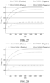
- FIG. 29 is a temperature rise curve diagram of the positive lead-out sheet 141 and the negative lead-out sheet 142 in the comparative example and Embodiment 1.
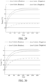
- FIG. 30 is a temperature rise curve diagram of the positive lead-out sheet 141 and the negative lead-out sheet 142 in the comparative example and Embodiment 2.
- FIG. 31 is a temperature rise curve diagram of the positive lead-out sheet 141 and the negative lead-out sheet 142 in the comparative example and Embodiment 3.
- FIG. 32 is a temperature rise curve diagram of the positive lead-out sheet 141 and the negative lead-out sheet 142 in the comparative example and Embodiment 4.
- FIG. 33 is a temperature rise curve diagram of the positive lead-out sheet 141 and the negative lead-out sheet 142 in the comparative example and Embodiment 5.
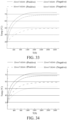
- FIG. 34 is a temperature rise curve diagram of the positive lead-out sheet 141 and the negative lead-out sheet 142 in the comparative example and Embodiment 6.
- FIG. 35 is a temperature rise curve diagram of the positive lead-out sheet 141 and the negative lead-out sheet 142 in the comparative example and Embodiment 7.
- FIG. 36 is a temperature rise curve diagram of the positive lead-out sheet 141 and the negative lead-out sheet 142 in the comparative example and Embodiment 8.
- the positive lead-out sheet 141 and the negative lead-out sheet 142 have a same structure and each include a first connection sheet and a second connection sheet that are connected.
- the second connection sheet of the positive lead-out sheet 141 is directly opposite to the fifth plate piece 115 and is fixedly connected to a positive tab of the electrode core 120
- the first connection sheet of the positive lead-out sheet 141 is directly opposite to the first plate piece 111 and is connected to the positive conductive post 131
- the second connection sheet of the negative lead-out sheet 142 is directly opposite to the fifth plate piece 115 and is fixedly connected to a negative tab of the electrode core 120
- the first connection sheet of the negative lead-out sheet 142 is directly opposite to the second plate piece 112 and is connected to the negative conductive post 132.
- first connection sheet of the positive lead-out sheet 141 may be denoted as the positive first connection sheet 141a
- the second connection sheet of the positive lead-out sheet 141 may be denoted as the positive second connection sheet 141b.
- first connection sheet of the negative lead-out sheet 142 may be denoted as the negative first connection sheet 142a
- the second connection sheet of the negative lead-out sheet 142 may be denoted as the negative second connection sheet 142b.
- sizes of both the positive first connection sheet 141a and the negative first connection sheet 142a range from 0.8 mm to 0.2 mm in the length direction of the battery housing.
- the battery housing 110 includes the first plate piece 111 and the second plate piece 112 that are opposite to each other in the length direction.
- the first connection sheet (that is, the positive first connection sheet 141a) of the positive lead-out sheet 141 is parallel to the first plate piece 111
- the first connection sheet (that is, the negative first connection sheet 142a) of the negative lead-out sheet 142 is parallel to the second plate piece 112.
- the first insulating spacer 161 is arranged between the positive lead-out sheet 141 and the first plate piece 111, and the positive conductive post 131 passes through the first insulating spacer 161 and is connected to the positive lead-out sheet 141.
- the second insulating spacer 162 is arranged between the negative lead-out sheet 142 and the second plate piece 112, and the negative conductive post 132 passes through the second insulating spacer 162 and is connected to the negative lead-out sheet 142. This can avoid direct contact of the positive lead-out sheet 141 and the negative lead-out sheet 142 from the battery housing 110, and improve overall security performance of the battery 100.
- At least a part of the first insulating spacer 161 is arranged between the second connection sheet of the positive lead-out sheet 141 and the fifth plate piece 115, and at least a part of the second insulating spacer 162 is arranged between the second connection sheet of the negative lead-out sheet 142 and the fifth plate piece 115.
- the first insulating spacer 161 may not only separate the positive lead-out sheet 141 from the first plate piece 111, but also separate the positive lead-out sheet 141 from the fifth plate piece 115.
- the second insulating spacer 162 may not only separate the negative lead-out sheet 142 from the second plate piece 112, but also separate the negative lead-out sheet 142 from the fifth plate piece 115.
- the first insulating spacer 161 includes the first support piece 161a and the first insulating piece connected to the first support piece 161a.
- the inner end and the outer end of the first support piece 161a respectively abut against an end of the electrode core 120 of the battery 100 and the first plate piece 111, and the first insulating piece is matched with the positive lead-out sheet 141 and is arranged between the positive lead-out sheet 141 and the battery housing 110.
- the second insulating spacer 162 includes the second support piece 162a and the second insulating piece connected to the second support piece 162a.
- the first insulating piece includes the first insulating piece vertical plate 161b and the first insulating piece horizontal plate 161c.
- the first insulating piece vertical plate 161b is arranged between the positive first connection sheet 141a and the first plate piece 111, and the first insulating piece horizontal plate 161c is arranged between the positive second connection sheet 141b and the fifth plate piece 115.
- the second insulating piece includes the second insulating piece vertical plate 162b and the second insulating piece horizontal plate 162c.
- the second insulating piece vertical plate 162b is arranged between the negative first connection sheet 142a and the second plate piece 112, and the second insulating piece horizontal plate 162c is arranged between the negative second connection sheet 142b and the fifth plate piece 115.
- a thickness of the first support piece 161a in the length direction of the battery housing 110 is greater than a thickness of the first insulating piece vertical plate 161b in the length direction of the battery housing 110. Therefore, the first support piece 161a can abut against one end of the electrode core 120.
- a thickness of the second support piece 162a in the length direction of the battery housing 110 is greater than a thickness of the second insulating piece vertical plate 162b in the length direction of the battery housing 110. Therefore, the second support piece 162a can abut against the other end of the electrode core 120. Therefore, the first support piece 161a and the second support piece 162a can jointly abut against the electrode core 120 in the length direction of the battery housing 110, to avoid movement of the electrode core 120 in the length direction of the battery housing 110.
- the first insulating piece vertical plate 161b is arranged between the positive first connection sheet 141a and the first plate piece 111
- the first insulating piece horizontal plate 161c is arranged between the positive second connection sheet 141b and the fifth plate piece 115
- the second insulating piece vertical plate 162b is arranged between the negative first connection sheet 142a and the second plate piece 112
- the second insulating piece horizontal plate 162c is arranged between the negative second connection sheet 142b and the fifth plate piece 115.
- the positive lead-out sheet 141 and the first insulating piece each may be configured as an "L"-shaped structure, and the positive lead-out sheet 141 may be arranged on the inner side of the first insulating piece and the two are bonded to each other.
- the negative lead-out sheet 142 and the second insulating piece each may also be configured as an "L"-shaped structure, and the negative lead-out sheet 142 may be arranged on the inner side of the second insulating spacer piece and the two are bonded to each other.
- sizes of the first insulating piece vertical plate 161b and the positive first connection sheet 141a each range from 0.3 mm to 1.5 mm in the length direction of the battery housing 110. That is, a thickness of the first insulating piece vertical plate 161b and a thickness of the positive first connection sheet 141a each range from 0.3 mm to 1.5 mm.
- the battery 100 in the embodiments of the present disclosure further includes a sealing ring.
- the sealing ring is hermetically connected between the conductive post and the battery housing 110, the sealing ring is configured as an elastic member, and the sealing ring is an insulating member, so that the lead-out sheet can be effectively insulated from the battery housing 110.
- An initial size of the sealing ring in an axial direction of the sealing ring is d1
- a size of the sealing ring after compression in the axial direction of the sealing ring is d2
- d1 and d2 meet 0.5 ⁇ d2/d1 ⁇ 0.9. Units of d1 and d2 are both mm.
- the sealing ring is sleeved on the conductive post and is sandwiched between an inner wall of the battery housing 110 and the lead-out sheet.
- an initial size d1 of the sealing ring in the axial direction of the sealing ring may be understood as an axial size of the sealing ring that is elastically reset after decompression (d1 is a distance between two end surfaces that are opposite to each other in the axial direction of the sealing ring after the sealing ring is reset).
- d2 may be understood as a distance between two opposite surfaces of the sealing ring along the axial direction of the sealing ring. One surface of the two surfaces is a surface of the sealing ring in contact with the inner wall of the battery housing, and the other surface is a surface of the sealing ring in contact with the lead-out sheet.
- the initial size of the sealing ring in the axial direction is a size of the sealing ring in the axial direction after the sealing ring is not compressed. After the sealing ring is compressed, a size of the sealing ring decreases in the axial direction. However, a ratio between the size of the compressed sealing ring to the initial size is limited. This can ensure that the sealing ring has a compression amount, facilitate installing a spacer on the lead-out sheet and the conductive post, and can also ensure sealing performance between the lead-out sheet and the battery housing 110 and sealing performance between the conductive post and the sealing ring. In addition, the capacity of the battery is improved without changing a size of the battery.
- a size of the sealing ring in the axial direction decreases. Therefore, a size of the sealing ring in a radial direction naturally increases, two side surfaces of the sealing ring in the axial direction each are configured as a ring, an outer end of the sealing ring in the axial direction is in contact with the inner wall of the battery housing 110, and an inner end of the sealing ring in the axial direction is in contact with the lead-out sheet. Therefore, the two ends of the sealing ring in the axial direction are sandwiched between the battery housing 110 and the lead-out sheet.
- At least one of a width of a contact area between the sealing ring and the inner wall of the battery housing 110 and a width of a contact area between the sealing ring and the lead-out sheet is W, and W meets 1.2 mm ⁇ W ⁇ 2.5 mm. This ensures sealing between the sealing ring and the inner wall of the battery housing 110, and sealing between the sealing ring and the lead-out sheet.
- the width of the contact between the sealing ring and the inner wall of the battery housing 110 may be understood as a distance between two outer contours of the contact area between the sealing ring and the inner wall of the battery housing 110 in the radial direction of the sealing ring.
- the width of the contact area between the sealing ring and the lead-out sheet may be understood as a distance between two outer contours of the contact area between the sealing ring and the lead-out sheet in the radial direction of the sealing ring.
- the sealing ring includes a first sealing ring 151 and a second sealing ring 152.
- the first sealing ring 151 is sleeved on the positive conductive post, a part of the first sealing ring 151 extends into a via 102 of the first plate piece 111, and the other part of the first sealing ring 151 is sandwiched between a positive conductive post flange 131e of the positive conductive post and the first plate piece 111.
- the second sealing ring 152 is sleeved on the negative conductive post, a part of the second sealing ring 152 extends into a via 102 of the second plate piece 112, and the other part of the second sealing ring 152 is sandwiched between a negative conductive post flange 132e of the negative conductive post and the second plate piece 112.
- a spacer is arranged between the lead-out sheet and the battery housing 110, the conductive post and the sealing ring both pass through the spacer, an inner end of the conductive post is connected to the lead-out sheet, and an inner end of the sealing ring abuts against the lead-out sheet.
- the sealing ring is sleeved on an outer peripheral surface of the conductive post.
- the sealing ring, together with the conductive post, may be inserted into a via that is on the battery housing 110 and through which the conductive post passes. Alternatively, the sealing ring may not enter the via, so that the sealing ring can ensure that the conductive post does not move in a radial direction of the via, to avoid contact with an inner peripheral surface of the via.
- a part of the inner end of the sealing ring may be matched with a step piece of the spacer, to limit movement of the sealing ring and the conductive post in the radial direction of the via, and the other part of the inner end of the sealing ring may abut against the lead-out sheet.
- the spacer includes a support piece and an insulating piece connected to the support piece. An inner end and an outer end of the support piece respectively abut against the electrode core 120 and the battery housing 110 of the battery 100.
- the insulating piece is matched with the lead-out sheet and is arranged between the lead-out sheet and the battery housing 110.
- the insulating piece and the lead-out sheet may be approximately in a same structure, for example, each may be configured as an "L" shape.
- the insulating piece includes an insulating piece vertical plate and an insulating piece horizontal plate that are vertically connected.
- the lead-out sheet includes a first connection sheet and a second connection sheet that are vertically connected.
- the insulating piece vertical plate may be arranged between the first connection sheet and one side plate of the housing, and the insulating piece horizontal plate may be arranged between the second connection sheet and one side plate of the housing.
- the battery housing 110 is configured as an aluminum alloy piece, and a plate thickness of the lower housing and a plate thickness of the sixth plate piece 116 range from 0.2 mm to 0.5 mm. Because hardness of the aluminum alloy piece is low, the plate thickness of the lower housing and the plate thickness of the sixth plate piece 116 need to be set to be larger, to ensure structural strength of the battery housing 110.
- the battery housing 110 is configured as a stainless steel piece or a nickel plated steel piece, and the plate thickness of the lower housing and the plate thickness of the sixth plate piece 116 range from 0.05 mm to 0.2 mm. Because hardness of the stainless steel piece or the nickel plated steel piece is high, the plate thickness of the lower housing and the plate thickness of the sixth plate piece 116 may be set to be smaller. This reduces manufacturing costs of the battery housing 110 while ensuring structural strength of the battery housing 110.
- the plate thickness of the lower housing is a plate thickness of any one of the first plate piece 111, the second plate piece 112, the third plate piece 113, the fourth plate piece 114, and the fifth plate piece 115.
- the positive lead-out sheet 141 and the negative lead-out sheet 142 are arranged in the battery housing 110, and the positive lead-out sheet 141 and the negative lead-out sheet 142 are respectively connected to a positive tab and a negative tab of the electrode core 120.
- the positive lead-out sheet 141 includes the positive first connection sheet 141a
- the negative lead-out sheet 142 includes the negative first connection sheet 142a.
- the positive first connection sheet 141a and the negative first connection sheet 142a are distributed at opposite ends of the electrode core 120 in the length direction of the battery housing 110.
- a distance between the positive first connection sheet 141a and the negative first connection sheet 142a in the length direction of the battery housing 110 is L1
- a size of the battery 100 in the length direction of the battery housing 110 is L.
- L1 and L meet 0.95 ⁇ L1/L ⁇ 0.99. It may be understood that the positive first connection sheet 141a has a first surface facing the negative first connection sheet 142a, the negative first connection sheet 142a has a second surface facing the positive first connection sheet 141a, and a distance between the first surface of the positive first connection sheet 141a and the second surface of the negative first connection sheet 142a in the length direction of the battery housing 110 is L1.
- the battery housing 110 has a first surface and a second surface that are opposite to each other in the length direction, and a distance between the first surface and the second surface of the battery housing 110 in the length direction of the battery housing 110 is L. It should be noted that the length direction of the battery housing 110 is consistent with the length direction of the battery 100.
- the positive lead-out sheet 141 includes the positive second connection sheet 141b and the positive first connection sheet 141a that are connected.
- the negative lead-out sheet 142 includes the negative second connection sheet 142b and the negative first connection sheet 142a that are connected. Therefore, "L1" in the present disclosure is a distance between an inner surface of the positive first connection sheet 141a and an inner surface of the negative first connection sheet 142a in the length direction of the battery housing 110.
- L1 and L meet 0.95 ⁇ L1/L ⁇ 0.99. It can be ensured that the positive lead-out sheet 141 and the negative lead-out sheet 142 have enough conductive performance, and the positive lead-out sheet 141 and the negative lead-out sheet 142 do not occupy too much internal space of the battery housing 110, and in particular, do not occupy much space of the battery housing 110 in the length direction.
- a thickness of the positive first connection sheet 141a ranges from 0.6 mm to 2 mm
- a thickness of the negative first connection sheet 142a ranges from 0.6 mm to 2 mm.
- the thickness of the positive first connection sheet 141a is a size of the positive first connection sheet 141a in the length direction of the battery housing
- the thickness of the negative first connection sheet 142a is a size of the negative first connection sheet 142a in the length direction of the battery housing.
- the positive lead-out sheet 141 is configured as an "L" shape and may be an integrally formed member
- the negative lead-out sheet 142 is configured as an "L” shape and may be an integrally formed member.
- the thickness of the positive lead-out sheet 141 may be a thickness of the positive first connection sheet 141a
- the thickness of the negative lead-out sheet 142 may be a thickness of the negative first connection sheet 142a. This is because the thickness of the positive first connection sheet 141a and the thickness of the negative first connection sheet 142a affect a degree of space occupied by the positive lead-out sheet 141 and the negative lead-out sheet 142 in the length direction of the battery housing 110.
- the thickness of the positive lead-out sheet 141 is limited to 0.6 mm to 2 mm
- the thickness of the negative lead-out sheet 142 is limited to 0.6 mm to 2 mm.
- the positive lead-out sheet 141 and the negative lead-out sheet 142 may not occupy too much internal space of the battery housing 110, and in particular, do not occupy much space of the battery housing 110 in the length direction. Therefore, a capacity of the battery is improved without changing a size of the battery.
- the positive conductive post 131 is arranged on the first plate piece 111
- the negative conductive post 132 is arranged on the second plate piece 112. However, the positive conductive post 131 does not directly contact the first plate piece 111, and the negative conductive post 132 does not directly contact the second plate piece 112.
- the positive first connection sheet 141a is parallel to the first plate piece 111 and is connected to the positive conductive post 131
- the negative first connection sheet 142a is parallel to the second plate piece 112 and is connected to the negative conductive post 132
- a distance between the inner surface of the positive first connection sheet 141a and an inner surface of the negative lead-out sheet in the length direction of the battery housing 110 is "L1".
- the electrode core 120 has a first end surface and a second end surface opposite to each other.
- a positive tab of the electrode core 120 is led out from the first end surface.
- a negative tab of the electrode core 120 is led out from the second end surface.
- a distance between the first end surface of the electrode core 120 and the positive first connection sheet 141a in the length direction of the battery housing 110 ranges from 2 mm to 12 mm, and a distance between the second end surface of the electrode core 120 and the negative first connection sheet 142a in the length direction of the battery housing 110 ranges from 2 mm to 12 mm.
- the battery housing 110 further includes the third plate piece 113 and the fourth plate piece 114 that are opposite to each other in a width direction.
- a distance between an inner surface of the third plate piece 113 and an inner surface of the fourth plate piece 114 in the width direction of the battery housing 110 is H1
- a size of the battery 100 in the width direction of the battery housing 110 is H.
- H1 and H meet 0.92 ⁇ H1/H ⁇ 0.98. This ensures that plate thicknesses of the third plate piece 113 and the fourth plate piece 114 can provide enough strength for the battery housing 110, and a capacity of the battery 100 is not affected by reduced space in the battery housing 110 because the plate thicknesses of the third plate piece 113 and the fourth plate piece 114 are large.
- the width direction of the battery housing 110 is consistent with the width direction of the battery 100.
- the battery housing 110 further includes the fifth plate piece 115 and the sixth plate piece 116 that are opposite to each other in a thickness direction.
- a distance between an inner surface of the fifth plate piece 115 and an inner surface of the sixth plate piece 116 in the thickness direction of the battery housing 110 is D1
- a size of the battery 100 in the thickness direction of the battery housing 110 is D.
- L>H>D, and D1 and D meet 0.93 ⁇ D1/D ⁇ 0.99. Therefore, thicknesses of the fifth plate piece 115 and the sixth plate piece 116 are not excessively large, so that the fifth plate piece 115 and the sixth plate piece 116 do not excessively occupy internal space of the battery housing 110 when a volume of the battery housing 110 is fixed.
- the fifth plate piece 115 and the sixth plate piece 116 have a certain thickness, and this may further ensure that the battery housing 110 has sufficient structural strength. It should be noted that the thickness direction of the battery housing 110 is consistent with the thickness direction of the battery 100.
- the positive second connection sheet 141b is arranged on the positive first connection sheet 141a and extends toward the inside of the battery housing 110, the negative second connection sheet 142b is connected to the negative first connection sheet 142a and extends toward the inside of the battery housing 110, and both the positive second connection sheet 141b and the negative second connection sheet 142b are parallel to the fifth plate piece 115 and the sixth plate piece 116. Specifically, both the positive second connection sheet 141b and the negative second connection sheet 142b are bonded to an inner surface of the fifth plate piece 115.
- the battery in the embodiments of the present disclosure includes the lower housing and an upper housing.
- the upper housing and the lower housing may be connected by welding. After the lower housing and the upper housing are fastened together, both the upper housing and the lower housing limit accommodation space that accommodates the electrode core 120.
- the lower housing includes: the first plate piece 111 and the second plate piece 112, the first plate piece 111 and the second plate piece 112 being opposite to each other in the length direction of the battery 100; the third plate piece 113 and the fourth plate piece 114, the third plate piece 113 and the fourth plate piece 114 being opposite to each other in the width direction of the battery 100, the third plate piece 113 being separately connected to one end on a same side of the first plate piece 111 and the second plate piece 112 in the width direction of the battery 100, and the fourth plate piece 114 being separately connected to the other end on the same side of the first plate piece 111 and the second plate piece 112 in the width direction of the battery 100; and the fifth plate piece 115, an outer peripheral edge of the fifth plate piece 115 being separately connected to one end on a same side of the first plate piece 111, the second plate piece 112, the third plate piece 113, and the fourth plate piece 114 in the thickness direction of the battery 100.
- the first plate piece 111, the second plate piece 112, the third plate piece 113, and the fourth plate piece 114 are configured as peripheral side walls of the lower housing. Therefore, an opening of the lower housing is very large, so that the electrode core 120 can be conveniently installed inside the battery housing 110, to improve installation efficiency of the battery 100.
- first plate piece 111, the second plate piece 112, the third plate piece 113, the fourth plate piece 114, and the fifth plate piece 115 are an integrally formed member.
- the lower housing may be integrally formed through sheet metal stamping. Therefore, molding efficiency of the lower housing is greatly increased, and structural strength of the lower housing is also enhanced.
- the upper housing is configured as the sixth plate piece 116, and the sixth plate piece 116 and the fifth plate piece 115 are directly opposite to each other in the thickness direction of the battery 100.
- the battery according to the present disclosure includes the battery housing 110, the electrode core 120, the lead-out piece, and the spacer.
- the electrode core 120 and the lead-out sheet are arranged in the battery housing 110, and the lead-out sheet is connected to a tab of the electrode core 120.
- a part of the spacer is sandwiched between the lead-out sheet and the battery housing 110, and the other part of the spacer is sandwiched between an end of the electrode core 120 and the battery housing 110.
- the spacer in the present disclosure may not only separate the lead-out sheet from the battery housing 110, to avoid a short circuit phenomenon caused by contact between the lead-out sheet and the battery housing 110, but also abut against two ends of the electrode core 120, to avoid movement of the electrode core 120 in a direction of the battery housing 110 and improve stability of the electrode core. Therefore, it is ensured that a tab arranged on the electrode core 120 does not move, and connection stability between the tab and the lead-out sheet is improved.
- the spacer includes a support piece and an insulating piece connected to the support piece, the support piece is sandwiched between an end of the electrode core 120 and the battery housing 110, and the insulating piece is matched with the lead-out sheet, and is sandwiched between the lead-out sheet and the battery housing 110.
- the insulating piece is an insulating piece, but also the support piece is an insulating member.
- the support piece and the insulating piece each may be an integrally formed member.
- Both ends of the support piece may abut against an end of the electrode core 120 and an inner wall of the battery housing 110, and the insulating piece may be matched with the lead-out sheet.
- the insulating piece is further spaced between the lead-out sheet and the battery housing 110, to avoid a leakage phenomenon caused by direct contact between the lead-out sheet and the battery housing 110.
- the lead-out sheet may be configured as an "L" shape and includes a first connection sheet and a second connection sheet, the first connection sheet is connected to the second connection sheet, the first connection sheet is parallel to a side plate of the battery housing 110 in the length direction, and the second connection sheet is parallel to a side plate of the battery housing 110 in the thickness direction.
- the insulating piece is also configured as an "L" shape and includes an insulating piece vertical plate and an insulating piece horizontal plate.
- the insulating piece vertical plate is connected to the insulating piece horizontal plate, the insulating piece vertical plate is arranged between the first connection sheet and a side plate of the battery housing 110 in the length direction, and the insulating piece horizontal plate is arranged between the second connection sheet and a side plate of the battery housing 110 in the thickness direction.
- a size of the support piece in the length direction of the battery housing 110 is greater than a size of the insulating piece vertical plate in the length direction of the battery housing 110, and the support piece protrudes towards a center of the battery housing 110 relative to the insulating piece vertical plate, so that the support piece can abut against an end of the electrode core 120, and an end of the electrode core 120 does not abut against the insulating piece vertical plate.
- the L-shaped lead-out sheet may be arranged inside the L-shaped insulating piece, so that the insulating piece can package a whole of the lead-out sheet, to avoid direct contact with the battery housing 110.
- an outer surface of the support piece is flush with an outer surface of the insulating piece vertical plate, and an inner surface of the support piece is flush with an inner end of the insulating piece horizontal plate.
- a size of the support piece that protrudes toward the inside relative to the insulating piece vertical plate is a size of the insulating piece horizontal plate in the length direction.
- an electrolyte immersion through hole 101 and a via through which a conductive post passes are provided on the insulating piece vertical plate.
- the conductive post passes through the via on the insulating piece and is connected to the first connection sheet.
- the electrolyte immersion through hole 101 provided on the insulating piece may facilitate injection of electrolytes into the battery housing 110.
- gas inside the battery housing 110 may also be discharged out of the electrolyte immersion through hole 101. It may be understood that the electrolyte immersion through hole 101 is directly opposite to an explosion proof valve and a liquid injection hole of the battery 100 on the battery housing 110 in the length direction of the battery housing 110.
- the battery housing 110 includes the first plate piece 111 and the second plate piece 112 that are opposite to each other in the length direction of the battery housing 110, the third plate piece 113 and the fourth plate piece 114 that are opposite to each other in the width direction of the battery housing 110, and the fifth plate piece 115 and the sixth plate piece 116 that are opposite to each other in the thickness direction of the battery housing 110.
- the first plate piece 111, the second plate piece 112, the third plate piece 113, the fourth plate piece 114, and the fifth plate piece 115 are configured as a lower housing with one end open, and the sixth plate piece 116 is fastened to the lower housing to block the open end.
- the lead-out sheets include the positive lead-out sheet 141 and the negative lead-out sheet 142.
- the positive lead-out sheet 141 is separately connected to the positive conductive post 131 and a positive tab of the electrode core 120
- the negative lead-out sheet 142 is separately connected to the negative conductive post 132 and a negative tab of the electrode core 120.
- a spacer includes the first insulating spacer 161 and the second insulating spacer 162.
- a spacer vertical plate of the first insulating spacer 161 is arranged between the first plate piece 111 and a first connection sheet of the positive lead-out sheet 141
- a spacer horizontal plate of the first insulating spacer 161 is arranged between the fifth plate piece 115 and a second connection sheet of the positive lead-out sheet 141
- a spacer vertical plate of the second insulating spacer 162 is arranged between the second plate piece 112 and a first connection sheet of the negative lead-out sheet 142
- a spacer horizontal plate of the second insulating spacer 162 is arranged between the fifth plate piece 115 and a second connection sheet of the negative lead-out sheet 142.
- the electrode core 120 is directly arranged in the lower housing, and then the tab is welded to the lead-out sheet.
- a welding method may be laser welding, resistance welding, or another welding method.
- the lead-out sheet is designed in an L shape, to facilitate welding with the tab.
- the tab may be naturally straightened and stacked with the lead-out sheet after the electrode core 120 is integrally assembled into the housing. Then, the tab may be welded together with the lead-out sheet, to avoid a risk of positive or negative electrode contact due to a bent tab, reduce a size of a tab, increase utilization of a metal current collector, improve a process yield, and reduce product costs.
- the upper housing (the sixth plate piece 116) is assembled. After the upper housing and the lower housing are assembled, the upper housing and the lower housing are sealed and connected through laser welding or crimping, so that the upper housing and the lower housing form a sealing body.
- liquid injection may be performed through a liquid injection hole. After the liquid injection is completed, the liquid injection hole needs to be sealed, and a sealing method is metal sheet welding or rubber plug sealing.
- An explosion proof valve of the battery 100 is arranged on the first plate piece 111 or the second plate piece 112, and one or more explosion proof valves may be arranged on the first plate piece 111 or the second plate piece 112.
- the explosion proof valve is formed by laser scribing or direct stamping on a side plate on the battery housing 110. Alternatively, holes of a shape and size the same as the explosion proof valve may be stamped on the battery housing 110, and then the explosion proof valve is welded to the battery housing 110.
- the lead-out sheet is configured as an "L" shape.
- the second connection sheet is connected to one side of the first connection sheet and extends toward the inside of the housing, and the second connection sheet that extends toward the inside of the housing may be welded and fixed with a plurality of tabs, so that the plurality of tabs are not bent too much, and the tabs are flatter during welding and after welding.
- the lead-out sheet is configured as a "T" shape
- the second connection sheet is connected to a middle area of the first connection sheet and extends toward the inside of the battery housing 110. Because the "T" shaped lead-out sheet still has a second connection sheet extending toward the inside of the housing, the tabs can still be welded to the second connection sheet evenly, and the tabs are not bent too much, to greatly improve connection stability between the tabs and the lead-out sheet.
- One part of the plurality of tabs may be welded to one side surface of the second connection sheet in the thickness direction, and the other part of the plurality of tabs may be welded to the other side surface of the second connection sheet in the thickness direction.
- the first connection sheet may be parallel to the first plate piece 111 and the second plate piece 112, and the conductive post may be sleeved on the first plate piece 111 or the second plate piece 112 and connected to the first connection sheet.
- the conductive posts include the positive conductive post 131 and the negative conductive post 132.
- the lead-out sheets include the positive lead-out sheet 141 and the negative lead-out sheet 142.
- the positive conductive post 131 passes through the first plate piece 111 and is connected to the first connection sheet of the positive lead-out sheet 141
- the negative conductive post 132 passes through the second plate piece 112 and is connected to the first connection sheet of the negative lead-out sheet 142.
- the second connection sheet is parallel to the fifth plate piece 115 or the sixth plate piece 116.
- the conductive post in the battery 100 in the present disclosure includes the positive conductive post 131 and the negative conductive post 132
- the lead-out sheets include the positive lead-out sheet 141 and the negative lead-out sheet 142
- tabs include a positive tab and a negative tab.
- the positive lead-out sheet 141 includes the positive first connection sheet 141a and the positive second connection sheet 141b
- the negative lead-out sheet 142 includes the negative first connection sheet 142a and the negative second connection sheet 142b.
- the spacer is arranged between the lead-out sheet and the battery housing 110, and the conductive post passes through the spacer and is connected to the lead-out sheet.
- the spacer may avoid direct contact between the lead-out sheet and the battery housing 110, to avoid a risk that the battery housing 110 is electrically charged, and improve security performance of the battery 100.
- the spacer includes a support piece and an insulating piece connected to the support piece, the support piece is sandwiched between an end of the electrode core 120 and the battery housing 110, and the insulating piece is matched with the lead-out sheet, and is sandwiched between the lead-out sheet and the battery housing 110.
- the insulating piece is an insulating piece, but also the support piece is an insulating member.
- the support piece and the insulating piece each may be an integrally formed member.
- the insulating piece is also configured as an "L" shape and includes an insulating piece vertical plate and an insulating piece horizontal plate.
- the insulating piece vertical plate is connected to the insulating piece horizontal plate, the insulating piece vertical plate is arranged between the first connection sheet and a side plate of the battery housing 110 in the length direction, and the insulating piece horizontal plate is arranged between the second connection sheet and a side plate of the battery housing 110 in the thickness direction.
- the battery pack 1000 includes the foregoing battery 100. Because the battery 100 is arranged in the battery pack 1000 according to the embodiments of the present disclosure, security performance of the battery pack 1000 is stronger, and power of the battery pack 1000 is further increased.
- vehicle 10000 The following briefly describes a vehicle 10000 according to the embodiments of the present disclosure.
- the vehicle 10000 according to the embodiments of the present disclosure includes the foregoing battery pack 1000. Because the foregoing battery pack 1000 is arranged on the vehicle 10000 according to the embodiments of the present disclosure, a driving range of the vehicle 10000 is significantly improved, and electrical security performance of the vehicle 10000 is also significantly improved.
- the vehicle 10000 includes the foregoing battery 100.
- the battery 100 in the foregoing embodiment is set, a driving range of the vehicle 10000 can be improved, and electrical security performance of the vehicle 10000 is also significantly improved.
Landscapes
- Chemical & Material Sciences (AREA)
- Chemical Kinetics & Catalysis (AREA)
- Electrochemistry (AREA)
- General Chemical & Material Sciences (AREA)
- Engineering & Computer Science (AREA)
- Aviation & Aerospace Engineering (AREA)
- Connection Of Batteries Or Terminals (AREA)
- Sealing Battery Cases Or Jackets (AREA)
- Secondary Cells (AREA)
Abstract
Description
- The present disclosure claims priority to and benefits of
Chinese Patent Application No. 202210515990.7, filed on May 12, 2022 Chinese Patent Application No. 202222993656.0, filed on November 10, 2022 - The present disclosure relates to the field of battery technologies, and specifically to a battery, a battery pack, and a vehicle.
- In a battery in the related art, a lead-out sheet is arranged in a battery housing and is connected between a tab of an electrode core and a conductive post, so that a current flows inside and outside the battery. However, in the related art, a lead-out sheet has a single size. Either a cross-sectional area of the lead-out sheet is too large, resulting in a waste of resources, or a cross-sectional area of the lead-out sheet is too small, resulting in a heating problem, and further causing a thermal security problem of the battery.
- The present disclosure aims to resolve at least one of the technical problems existing in the related art. Therefore, an objective of the present disclosure is to provide a battery with a strong current carrying capability, to ensure that during use, a temperature does not rise excessively due to a small current carrying area, and does not exceed an operating temperature range of the battery, to avoid a thermal security problem of the battery.
- The present disclosure further provides a battery pack having the battery described above.
- The present disclosure further provides a vehicle having the battery pack described above.
- The battery according to the present disclosure includes a battery housing, an electrode core, lead-out sheets, and conductive posts. The electrode core and the lead-out sheets are all arranged in the battery housing, the lead-out sheets are connected to the electrode core, and the conductive posts pass through the battery housing, so that the conductive posts are connected to the lead-out sheets. A relationship between a cross-sectional area slead of the lead-out sheets and a capacity C of the battery is C/slead≤15. A unit of slead is mm2, and a unit of C is Ah.
- According to the battery of the present disclosure, the relationship between the cross-sectional area slead of the lead-out sheets and the capacity C of the battery is configured as C/slead≤8. This ensures a current carrying capability of the lead-out sheet, and ensures that a temperature of the lead-out sheet does not rise excessively due to a small current carrying area during use of the battery, so that internal temperature distribution of the battery is not affected, an internal temperature in the battery does not exceed an operating temperature range of the battery, and a thermal security problem of the battery is not caused.
- Optionally, the relationship between the cross-sectional area slead of the lead-out sheets and the capacity C of the battery is 2≤C/slead≤15.
- Optionally, the relationship between the cross-sectional area slead of the lead-out sheets and the capacity C of the battery is 2≤C/slead≤15.
- Optionally, the lead-out sheets include a positive lead-out sheet and a negative lead-out sheet. The conductive posts include a positive conductive post and a negative conductive post. The positive lead-out sheet passes through the battery housing and is connected to the positive conductive post, and the negative lead-out sheet passes through the battery housing and is connected to the negative conductive post. A relationship between a cross-sectional area spositive lead of the positive lead-out sheet and the capacity C of the battery is 5≤C/spositive lead≤12, and a relationship between a cross-sectional area snegative lead of the negative lead-out sheet and the capacity C of the battery is 6≤C/snegative lead≤15. A cross section of the positive lead-out sheet and a cross section of the negative lead-out sheet each are a surface orthogonal to a current flow direction, units of spositive lead and snegative lead are mm2, and a unit of C is Ah.
- Optionally, the cross-sectional area of the positive lead-out sheet ranges from 14 mm2 to 150 mm2, the cross-sectional area of the negative lead-out sheet ranges from 10 mm2 to 130 mm2, and the capacity C of the battery ranges from 30 Ah to 400 Ah.
- Optionally, the positive lead-out sheet is an aluminum sheet, and the negative lead-out sheet is a copper sheet.
- Optionally, the positive lead-out sheet and the negative lead-out sheet each include a first connection sheet and a second connection sheet that are connected. The second connection sheet of the positive lead-out sheet is connected to a positive tab of the electrode core, the first connection sheet of the positive lead-out sheet is connected to the positive conductive post, the second connection sheet of the negative lead-out sheet is connected to a negative tab of the electrode core, and the first connection sheet of the negative lead-out sheet is connected to the negative conductive post.
- Optionally, a size of the first connection sheet in a length direction of the battery ranges from 0.8 mm to 2 mm.
- Optionally, a size of the first connection sheet in the length direction of the battery ranges from 0.6 mm to 2 mm.
- Optionally, the battery housing includes a first plate piece and a second plate piece that are opposite to each other in the length direction of the battery. The first connection sheet of the positive lead-out sheet and the first connection sheet of the negative lead-out sheet each are parallel to the first plate piece and the second plate piece.
- Optionally, the battery housing further includes a third plate piece and a fourth plate piece that are opposite to each other in a width direction of the battery, and a fifth plate piece and a sixth plate piece that are opposite to each other in a thickness direction of the battery. The second connection sheet of the positive lead-out sheet and the second connection sheet of the negative lead-out sheet each are parallel to the fifth plate piece and the sixth plate piece.
- Optionally, the first plate piece, the second plate piece, the third plate piece, the fourth plate piece, and the fifth plate piece are configured as a lower housing with one side open, and the sixth plate piece is fixedly connected to the lower housing to block an open end of the lower housing.
- Optionally, the battery further includes a first insulating spacer arranged in the battery housing. At least a part of the first insulating spacer is located between the positive lead-out sheet and the first plate piece, and the positive conductive post passes through the first insulating spacer and is connected to the positive lead-out sheet.
- Optionally, the battery further includes a second insulating spacer arranged in the battery housing. At least a part of the second insulating spacer is located between the negative lead-out sheet and the second plate piece, and the negative conductive post passes through the second insulating spacer and is connected to the negative lead-out sheet.
- Optionally, a relationship between a cross-sectional area s1 of the positive conductive post and the capacity C of the battery is 6/5≤C/s1≤16/3, and a relationship between a cross-sectional area s2 of the negative conductive post and the capacity C of the battery is 6/5≤C/s2≤8, where units of s1 and s2 are both mm2.
- Optionally, the cross-sectional area s1 of the positive conductive post and the cross-sectional area s2 of the negative conductive post range from 12 mm2 to 315 mm2, and the capacity C of the battery ranges from 30 Ah to 400 Ah.
- Optionally, the positive conductive post is an aluminum post, and the negative conductive post is a copper post.
- A battery pack according to the present disclosure includes the battery described above.
- A vehicle according to the present disclosure includes the battery described above or the battery pack described above.
- The additional aspects and advantages of the present disclosure will be provided in the following description, some of which will become apparent from the following description or may be learned from practices of the present disclosure.
- The foregoing and/or additional aspects and advantages of the present disclosure will become apparent and comprehensible from the following descriptions of the embodiments with reference to the accompanying drawings, where:
-
FIG. 1 is a diagram of a lower housing of a battery according to an embodiment of the present disclosure; -
FIG. 2 is a diagram of a battery according to an embodiment of the present disclosure; -
FIG. 3 is an enlarged diagram of a part C circled inFIG. 2 ; -
FIG. 4 is a diagram of a battery according to an embodiment of the present disclosure; -
FIG. 5 is an enlarged diagram of a part D circled inFIG. 4 ; -
FIG. 6 is a diagram in which a cross section of a first positive (negative) conductive post or a second positive (negative) conductive post is cylindrical according to an embodiment of the present disclosure; -
FIG. 7 is a diagram in which a cross section of a first positive (negative) conductive post or a second positive (negative) conductive post is racetrack-shaped according to an embodiment of the present disclosure; -
FIG. 8 is a cross-sectional view of a battery according to an embodiment of the present disclosure; -
FIG. 9 is an enlarged diagram of a part E circled inFIG. 8 ; -
FIG. 10 is an enlarged diagram of a part H circled inFIG. 8 ; -
FIG. 11 is a diagram of a first insulating spacer according to an embodiment of the present disclosure; -
FIG. 12 is a diagram of cooperation of a second insulating spacer and a negative lead-out sheet according to an embodiment of the present disclosure; -
FIG. 13 is a diagram of a positive lead-out sheet according to an embodiment of the present disclosure; -
FIG. 14 is a diagram of a negative lead-out sheet according to an embodiment of the present disclosure; -
FIG. 15 is an exploded view of a battery according to an embodiment of the present disclosure; -
FIG. 16 is a diagram of a battery in a direction according to an embodiment of the present disclosure; -
FIG. 17 is a diagram of a battery in another direction according to an embodiment of the present disclosure; -
FIG. 18 is a diagram of a battery in still another direction according to an embodiment of the present disclosure; -
FIG. 19 is a diagram of cooperation between a positive conductive post, a sealing ring, and a battery housing of a battery according to another embodiment of the present disclosure; -
FIG. 20 is a diagram of cooperation between a negative conductive post, a sealing ring, and a battery housing of a battery according to still another embodiment of the present disclosure; -
FIG. 21 is a temperature rise curve diagram of a positive conductive post and a negative conductive post in a comparative example andEmbodiment 1; -
FIG. 22 is a temperature rise curve diagram of a positive conductive post and a negative conductive post in a comparative example andEmbodiment 2; -
FIG. 23 is a temperature rise curve diagram of a positive conductive post and a negative conductive post in a comparative example andEmbodiment 3; -
FIG. 24 is a temperature rise curve diagram of a positive conductive post and a negative conductive post in a comparative example andEmbodiment 4; -
FIG. 25 is a temperature rise curve diagram of a positive conductive post and a negative conductive post in a comparative example and Embodiment 5; -
FIG. 26 is a temperature rise curve diagram of a positive conductive post and a negative conductive post in a comparative example andEmbodiment 6; -
FIG. 27 is a temperature rise curve diagram of a positive conductive post and a negative conductive post in a comparative example and Embodiment 7; -
FIG. 28 is a temperature rise curve diagram of a positive conductive post and a negative conductive post in a comparative example and Embodiment 8; -
FIG. 29 is a temperature rise curve diagram of a positive lead-out sheet and a negative lead-out sheet in a comparative example andEmbodiment 1; -
FIG. 30 is a temperature rise curve diagram of a positive lead-out sheet and a negative lead-out sheet in a comparative example andEmbodiment 2; -
FIG. 31 is a temperature rise curve diagram of a positive lead-out sheet and a negative lead-out sheet in a comparative example andEmbodiment 3; -
FIG. 32 is a temperature rise curve diagram of a positive lead-out sheet and a negative lead-out sheet in a comparative example andEmbodiment 4; -
FIG. 33 is a temperature rise curve diagram of a positive lead-out sheet and a negative lead-out sheet in a comparative example and Embodiment 5; -
FIG. 34 is a temperature rise curve diagram of a positive lead-out sheet and a negative lead-out sheet in a comparative example andEmbodiment 6; -
FIG. 35 is a temperature rise curve diagram of a positive lead-out sheet and a negative lead-out sheet in a comparative example and Embodiment 7; -
FIG. 36 is a temperature rise curve diagram of a positive lead-out sheet and a negative lead-out sheet in a comparative example and Embodiment 8; -
FIG. 37 is a diagram of a battery pack according to an embodiment of the present disclosure; -
FIG. 38 is a diagram of a vehicle according to an embodiment of the present disclosure; and -
FIG. 39 is a diagram of a vehicle according to another embodiment of the present disclosure. - In the drawings:
Vehicle 10000,battery pack 1000,battery 100,battery housing 110,first plate piece 111,second plate piece 112,third plate piece 113,fourth plate piece 114,fifth plate piece 115,sixth plate piece 116,electrode core 120, positiveconductive post 131, first positiveconductive post 131a, second positiveconductive post 131b,first connection member 131c, first insulatingplate 131d, positive conductivepost flange edge 131e, negativeconductive post 132, first negativeconductive post 132a, second negativeconductive post 132b,second connection member 132c, second insulatingplate 132d, negativeconductive post flange 132e, positive lead-outsheet 141, positivefirst connection sheet 141a, positivesecond connection sheet 141b, negative lead-outsheet 142, negativefirst connection sheet 142a, negativesecond connection sheet 142b,first sealing ring 151,second sealing ring 152, first insulatingspacer 161,first support piece 161a, first insulating piecevertical plate 161b, first insulating piecehorizontal plate 161c, second insulatingspacer 162,second support piece 162a, second insulating piecevertical plate 162b, second insulating piecehorizontal plate 162c, electrolyte immersion throughhole 101, and via 102 - Embodiments of the present disclosure are described in detail below, and examples of the embodiments are shown in accompanying drawings, where the same or similar elements or the elements having same or similar functions are denoted by the same or similar reference numerals throughout the description. The embodiments described below with reference to the accompanying drawings are exemplary and used only for explaining the present disclosure, and should not be construed as a limitation on the present disclosure.
- A
battery 100 according to the embodiments of the present disclosure is described below with reference toFIG. 1 to FIG. 36 . - The battery according to the embodiments of the present disclosure includes a
battery housing 110, anelectrode core 120, and conductive posts. - The
electrode core 120 is arranged in thebattery housing 110, and the conductive post passes through thebattery housing 110, so that an inner end of the conductive post is connected to theelectrode core 120, and an outer end of the conductive post extends out of thebattery housing 110. Specifically, the inner end of the conductive post is connected to a tab of theelectrode core 120. In addition, a cross-sectional area of the conductive post is s, a capacity of the battery is C, and a relationship between s and C is C/s≤8, where a unit of s is mm2, and a unit of C is Ah. - It may be understood that a size of a cross-sectional area of the conductive post represents a current carrying capability of the conductive post. A larger cross-sectional area of the conductive post represents a stronger current carrying capability of the conductive post. In addition, a smallest cross-sectional area on the conductive post determines the current carrying capability of the conductive post. A cross section of the conductive post is a surface orthogonal to a current flow direction. If the conductive post is a cylinder, and the current flow direction of the conductive post is an axial direction of the conductive post, the cross section of the conductive post is a radial cross section, and a shape is circular. When the conductive post is designed by using a variable cross-section, a cross-sectional area of the conductive post may be understood as an area of a smallest cross section on the conductive post.
- After extensive experiments and arguments, the inventors of the present disclosure find that the following relationship is satisfied: C/s≤8. This ensures a current carrying capability of the conductive post of the
battery 100, and ensures that during use of thebattery 100, a temperature does not rise excessively due to a small current carrying area, and does not exceed an operating temperature range of thebattery 100, to avoid a thermal security problem of thebattery 100. - In some embodiments of the present disclosure, the relationship between the cross-sectional area s of the conductive post and the capacity C of the battery is 6/5≤C/s≤8. The inventors find that a ratio of the capacity C of the battery to the cross-sectional area s of the conductive post is not necessarily better when smaller. A ratio that is too small may cause an excessively large size of the conductive post, resulting in a redundant design.
- In some embodiments of the present disclosure, the conductive posts include a positive
conductive post 131 and a negativeconductive post 132. A relationship between a cross-sectional area s1 of the positiveconductive post 131 and the capacity C of the battery is 6/5≤C/s1≤16/3, and a relationship between a cross-sectional area s2 of the negativeconductive post 132 and the capacity C of the battery is 6/5≤C/s2≤8, where units of s1 and s2 are both mm2. It may be understood that, when the positiveconductive post 131 includes multiple positive posts that pass through thebattery housing 110 and are connected to positive tabs of theelectrode core 120, the cross-sectional area s1 of the positiveconductive post 131 is a sum of cross-sectional areas of the multiple positive posts. When the positive post is designed by using a variable cross section, a cross-sectional area of the positive post may be understood as an area of a smallest cross section on the positive post. When the negativeconductive post 132 includes multiple negative posts that pass through thebattery housing 110 and are connected to negative tabs of theelectrode core 120, the cross-sectional area s2 of the negativeconductive post 132 is a sum of cross-sectional areas of the multiple negative posts. When the negative post is designed by using a variable cross section, a cross-sectional area of the negative post may be understood as an area of a smallest cross section on the negative post. - Further, the relationship between the cross-sectional area s1 of the positive
conductive post 131 and the capacity C of the battery is 8/3≤C/s1≤16/3, and the relationship between the cross-sectional area s2 of the negativeconductive post 132 and the capacity C of the battery is 3≤C/s2≤8. - It should be noted that the positive
conductive post 131 of thebattery 100 may be made of aluminum materials, the negativeconductive post 132 may be made of copper materials, and conductivities of the aluminum materials and the copper materials are different. Copper has a stronger current carrying capability than aluminum when cross-sectional areas are the same. Therefore, to ensure same current carrying capabilities of the positiveconductive post 131 and the negativeconductive post 132, the cross-sectional area of the negativeconductive post 132 made of copper may be smaller. - In some embodiments of the present disclosure, the cross-sectional area s1 of the positive conductive post and the cross-sectional area s2 of the negative conductive post range from 12 mm2 to 315 mm2, and the capacity C of the battery ranges from 30 Ah to 400 Ah.
- The following describes a comparative example (that is, the related art) and
Embodiments 1 to 8 (that is, the embodiments of the present disclosure) in Table 1. In a same operating condition, batteries in the comparative example andEmbodiments 1 to 8 each are rapidly charged at a speed of 2C, and temperature rise curves of the positiveconductive post 131 and the negativeconductive post 132 are recorded. The cross-sectional area s1 of the positiveconductive post 131, the cross-sectional area s2 of the negativeconductive post 132, and the total capacity C of the battery in the comparative example andEmbodiments 1 to 8 are selected from data in Table 1 below.FIG. 21 is a temperature rise curve diagram of the positiveconductive post 131 and the negativeconductive post 132 in the comparative example andEmbodiment 1.FIG. 22 is a temperature rise curve diagram of the positiveconductive post 131 and the negativeconductive post 132 in the comparative example andEmbodiment 2.FIG. 23 is a temperature rise curve diagram of the positiveconductive post 131 and the negativeconductive post 132 in the comparative example andEmbodiment 3.FIG. 24 is a temperature rise curve diagram of the positiveconductive post 131 and the negativeconductive post 132 in the comparative example andEmbodiment 4.FIG. 25 is a temperature rise curve diagram of the positiveconductive post 131 and the negativeconductive post 132 in the comparative example and Embodiment 5.FIG. 26 is a temperature rise curve diagram of the positiveconductive post 131 and the negativeconductive post 132 in the comparative example andEmbodiment 6.FIG. 27 is a temperature rise curve diagram of the positiveconductive post 131 and the negativeconductive post 132 in the comparative example and Embodiment 7.FIG. 28 is a temperature rise curve diagram of the positiveconductive post 131 and the negativeconductive post 132 in the comparative example and Embodiment 8.Table 1 s1/mm2 s2/mm2 C/Ah C/s1 C/s2 Comparative example 40 40 400 10 10 Embodiment 112 12 30 2.5 2.5 Embodiment 220 20 100 5 5 Embodiment 330 30 180 6 6 Embodiment 440 30 240 6 8 Embodiment 5 80 80 300 3.75 3.75 Embodiment 6150 150 350 2.333333333 2.333333333 Embodiment 7 230 230 400 1.739130435 1.739130435 Embodiment 8 315 315 400 1.26984127 1.26984127 - Compared with the comparative example, in
Embodiments 1 to 8, temperature rises of the positiveconductive post 131 and the negativeconductive post 132 are lower, to ensure that the battery is in a good working state. - Further, as shown in
FIG. 3 andFIG. 5 , the positiveconductive post 131 includes a first positiveconductive post 131a, a second positiveconductive post 131b, and afirst connection member 131c. Both the first positiveconductive post 131a and the second positiveconductive post 131b pass through thebattery housing 110 and are connected to positive tabs of theelectrode core 120. Thefirst connection member 131c is arranged outside thebattery housing 110 and is electrically connected to the first positiveconductive post 131a and the second positiveconductive post 131b. The cross-sectional area s1 of the positiveconductive post 131 is a sum of a cross-sectional area of the first positiveconductive post 131a and a cross-sectional area of the second positiveconductive post 131b. - The negative
conductive post 132 includes a first negativeconductive post 132a, a second negativeconductive post 132b, and asecond connection member 132c. Both the first negativeconductive post 132a and the second negativeconductive post 132b pass through thebattery housing 110 and are connected to negative tabs of theelectrode core 120. Thesecond connection member 132c is arranged outside thebattery housing 110 and is electrically connected to the first negativeconductive post 132a and the second negativeconductive post 132b. The cross-sectional area s2 of the negativeconductive post 132 is a sum of a cross-sectional area of the first negativeconductive post 132a and a cross-sectional area of the second negativeconductive post 132b. - The
first connection member 131c is connected between an outer end of the first positiveconductive post 131a and an outer end of the second positiveconductive post 131b, so that a contact area between the first positiveconductive post 131a and the second positiveconductive post 131b is increased, and the positiveconductive post 131 can be connected to the outside more easily. Thesecond connection member 132c is connected between an outer end of the first negativeconductive post 132a and an outer end of the second negativeconductive post 132b, so that a contact area between the first negativeconductive post 132a and the second negativeconductive post 132b is increased, and the negativeconductive post 132 can be connected to the outside more easily. - In some embodiments of the present disclosure, cross sections of the first positive
conductive post 131a and the second positiveconductive post 131b are circular or obround-shaped, and cross sections of the first negativeconductive post 132a and the second negativeconductive post 132b are circular or obround-shaped. If a size of thebattery housing 110 in a thickness direction is large, the first positiveconductive post 131a, the second positiveconductive post 131b, the first negativeconductive post 132a, and the second negativeconductive post 132b with a circular cross section may be used. However, if the size of thebattery housing 110 in the thickness direction is small, the first positiveconductive post 131a, the second positiveconductive post 131b, the first negativeconductive post 132a, and the second negativeconductive post 132b with an obround-shaped cross section may be used. This can ensure that the first positiveconductive post 131a, the second positiveconductive post 131b, the first negativeconductive post 132a, and the second negativeconductive post 132b do not exceed the size of thebattery housing 110 in the thickness direction on the premise that the positiveconductive post 131 and the negativeconductive post 132 have sufficient current carrying capabilities. - In some embodiments of the present disclosure, as shown in
FIG. 1 to FIG. 4 andFIG. 15 to FIG. 20 , thebattery housing 110 includes afirst plate piece 111 and asecond plate piece 112 that are opposite to each other in a length direction of thebattery 100, athird plate piece 113 and afourth plate piece 114 that are opposite to each other in a width direction of thebattery 100, and afifth plate piece 115 and asixth plate piece 116 that are opposite to each other in the thickness direction of thebattery 100. A size of thebattery 100 in the length direction is greater than a size of thebattery 100 in the width direction, and the size of thebattery 100 in the width direction is greater than the size of thebattery 100 in the thickness direction. - The
first plate piece 111 and thesecond plate piece 112 are respectively connected to one end and the other end on a same side of thethird plate piece 113 and thefourth plate piece 114 in the length direction of thebattery 100. In other words, thefirst plate piece 111 is connected to one end on the same side of thethird plate piece 113 and thefourth plate piece 114 in the length direction of thebattery 100, and thesecond plate piece 112 is connected to the other end on the same side of thethird plate piece 113 and thefourth plate piece 114 in the length direction of thebattery 100. Thefifth plate piece 115 and thesixth plate piece 116 are respectively connected to one end and the other end on a same side of thethird plate piece 113 and thefourth plate piece 114 in the thickness direction of thebattery 100. In other words, thefifth plate piece 115 is connected to one end on the same side of thethird plate piece 113 and thefourth plate piece 114 in the thickness direction of thebattery 100, and thesixth plate piece 116 is connected to the other end on the same side of thethird plate piece 113 and thefourth plate piece 114 in the thickness direction of thebattery 100. - The positive
conductive post 131 is arranged on thefirst plate piece 111, the negativeconductive post 132 is arranged on thesecond plate piece 112, a first insulatingplate 131d is arranged between thefirst plate piece 111 and thefirst connection member 131c, and a second insulatingplate 132d is arranged between thesecond plate piece 112 and thesecond connection member 132c. This can effectively avoid an electrical connection between thefirst connection member 131c and thebattery housing 110, and an electrical connection between thesecond connection member 132c and thebattery housing 110. - Further, a first via through which the first positive
conductive post 131a passes and a second via through which the second positiveconductive post 131b passes are provided on thefirst plate piece 111, and a third via through which the first negativeconductive post 132a passes and a fourth via through which the second negativeconductive post 132b passes are provided on thesecond plate piece 112. - A positive lead-out
sheet 141 and a negative lead-outsheet 142 are further arranged in thebattery housing 110. The positive lead-outsheet 141 may be connected to a positive tab of theelectrode core 120, in addition, the positive lead-outsheet 141 is further connected to the positiveconductive post 131, the negative lead-outsheet 142 may be connected to a negative tab of theelectrode core 120, and in addition, the negative lead-outsheet 142 is further connected to the negativeconductive post 132. - As shown in
FIG. 9 and FIG. 10 , afirst sealing ring 151 is sleeved on the positiveconductive post 131, and thefirst sealing ring 151 is sandwiched between the positive lead-outsheet 141 and thefirst plate piece 111. Asecond sealing ring 152 is sleeved on the negativeconductive post 132, and thesecond sealing ring 152 is sandwiched between the negative lead-outsheet 142 and thesecond plate piece 112. In this way, the positiveconductive post 131 is limited by thefirst sealing ring 151, so that the positiveconductive post 131 does not contact an inner wall of a via that is on thefirst plate piece 111 and through which the positiveconductive post 131 passes, and the negativeconductive post 132 is limited by thesecond sealing ring 152, so that the negativeconductive post 132 does not contact an inner wall of a via that is on thesecond plate piece 112 and through which the negativeconductive post 132 passes. - A first insulating
spacer 161 is further arranged between the positive lead-outsheet 141 and thefirst plate piece 111. The positiveconductive post 131 passes through the first insulatingspacer 161 and is connected to the positive lead-outsheet 141. The first insulatingspacer 161 is an insulating member. The first insulatingspacer 161 can avoid contact between the positive lead-outsheet 141 and thebattery housing 110, to improve security performance of thebattery 100. - A second insulating
spacer 162 is further arranged between the negative lead-outsheet 142 and thesecond plate piece 112. The negativeconductive post 132 passes through the second insulatingspacer 162 and is connected to the negative lead-outsheet 142. The secondinsulating spacer 162 is an insulating member. The secondinsulating spacer 162 can avoid contact between the negative lead-outsheet 142 and thebattery housing 110, to improve security performance of thebattery 100. - Further, a first step piece that is matched with an inner end of the
first sealing ring 151 is arranged on an outer surface of the first insulatingspacer 161, and the first step piece may limit movement of thefirst sealing ring 151 and the positiveconductive post 131, to avoid direct contact between the positiveconductive post 131 and thebattery housing 110. A second step piece that is matched with an inner end of thesecond sealing ring 152 is arranged on an outer surface of the second insulatingspacer 162, and the second step piece may limit movement of thesecond sealing ring 152 and the negativeconductive post 132, to avoid direct contact between the negativeconductive post 132 and thebattery housing 110. - It may be understood that a part of an inner end of the positive
conductive post 131 is matched with a step piece on the first insulatingspacer 161, another part of the positiveconductive post 131 abuts against the positive lead-outsheet 141, a part of an inner end of the negativeconductive post 132 is matched with a step piece on the second insulatingspacer 162, and another part of the negativeconductive post 132 abuts against the negative lead-outsheet 142. - In some embodiments of the present disclosure, sizes of a first insulating piece
vertical plate 161b and a second insulating piecevertical plate 162b each range from 0.3 mm to 1.5 mm in a length direction of the battery housing. To ensure that the positive lead-outsheet 141 and the negative lead-outsheet 142 are insulated from thebattery housing 110, and minimize space occupied in the length direction of thebattery housing 110, when a thickness is less than 0.3 mm, welding heat may melt a spacer when a tab and a lead-out sheet are welded, resulting in insufficient insulation. When a thickness is greater than 1.5 mm, too much space of theelectrode core 120 is occupied, resulting in reduced space utilization, and a design capacity of thebattery 100 is affected. Therefore, after multiple experiments and adjustments by the inventors of the present disclosure, sizes of both the first insulating piecevertical plate 161b and the second insulating piecevertical plate 162b are selected as 0.3 mm to 1.5 mm in the length direction of thebattery housing 110. - As shown in
FIG. 11 and FIG. 12 , the first insulatingspacer 161 includes afirst support piece 161a and a first insulating piece connected to thefirst support piece 161a. An inner end and an outer end of thefirst support piece 161a respectively abut against theelectrode core 120 and thefirst plate piece 111 of thebattery 100, and the first insulating piece is matched with the positive lead-outsheet 141 and is arranged between the positive lead-outsheet 141 and thebattery housing 110. The secondinsulating spacer 162 includes asecond support piece 162a and a second insulating piece connected to thesecond support piece 162a. An inner end and an outer end of thesecond support piece 162a respectively abut against an end of theelectrode core 120 and thesecond plate piece 112, and the second insulating piece is matched with the negative lead-outsheet 142 and is arranged between the negative lead-outsheet 142 and thebattery housing 110. - The first insulating piece includes the first insulating piece
vertical plate 161b and a first insulating piecehorizontal plate 161c. The first insulating piecevertical plate 161b is arranged between a positivefirst connection sheet 141a and thefirst plate piece 111, and the first insulating piecehorizontal plate 161c is arranged between a positivesecond connection sheet 141b and a side plate of thebattery housing 110 in the thickness direction. The second insulating piece includes the second insulating piecevertical plate 162b and a second insulating piecehorizontal plate 162c. The second insulating piecevertical plate 162b is arranged between a negativefirst connection sheet 142a and thesecond plate piece 112, and the second insulating piecehorizontal plate 162c is arranged between a negativesecond connection sheet 142b and a side plate of thebattery housing 110 in the thickness direction. - In some embodiments of the present disclosure, the
first plate piece 111, thesecond plate piece 112, thethird plate piece 113, thefourth plate piece 114, and thefifth plate piece 115 are configured as a lower housing with one side open, and thesixth plate piece 116 is fixedly connected to the lower housing to block an open end of the lower housing. Therefore, theelectrode core 120 enters the inside of thebattery housing 110 not through a narrow channel, but through a very wide open end, to greatly reduce installation costs and save installation time. - Specifically, the first insulating piece
horizontal plate 161c is arranged between the positivesecond connection sheet 141b and thefifth plate piece 115, and the second insulating piecehorizontal plate 162c is arranged between the negativesecond connection sheet 142b and thefifth plate piece 115. - A size of the
first support piece 161a in the length direction of thebattery housing 110 is greater than a size of the first insulating piecevertical plate 161b in the length direction of thebattery housing 110, and a size of thesecond support piece 162a in the length direction of thebattery housing 110 is greater than a size of the second insulating piecevertical plate 162b in the length direction of thebattery housing 110. Therefore, thefirst support piece 161a and thesecond support piece 162a may firmly clamp theelectrode core 120 inside thebattery housing 110, to prevent theelectrode core 120 from moving inside thebattery housing 110. - In some embodiments of the present disclosure, an outer surface of the positive
conductive post 131 extends out of the battery housing and has a distance of 2 mm to 5 mm from an outer surface of thefirst plate piece 111, and an outer surface of the negativeconductive post 132 extends out of the battery housing and has a distance of 2 mm to 5 mm from an outer surface of thesecond plate piece 112. Therefore, it is ensured that the positiveconductive post 131 and the negativeconductive post 132 can have enough protrusion to connect to an external electrical component. In addition, when an overall length of thebattery 100 is fixed, space of thebattery 100 in the length direction is not excessively occupied, to ensure that thebattery 100 has enough capacity. - According to the
battery 100 in this embodiment of the present disclosure, theelectrode core 120 and the lead-out sheet are both arranged in thebattery housing 110, and the lead-out sheet and theelectrode core 120 are connected. Specifically, the lead-out sheet is connected to a tab of theelectrode core 120, the conductive post passes through thebattery housing 110, an inner end of the conductive post is connected to the lead-out sheet, and an outer end of the conductive post protrudes from thebattery housing 110, so that the conductive post can charge and discharge theelectrode core 120. - A relationship between a cross-sectional area slead of the lead-out sheet and a capacity C of the battery is C/slead≤15. It should be noted that a cross-sectional area on the lead-out sheet determines a current carrying capability of the lead-out sheet. Therefore, in this relationship, a ratio of the capacity of the battery to the cross-sectional area of the lead-out sheet indicates the current carrying capability of the lead-out sheet. It should be noted that a cross section of the lead-out sheet is a surface orthogonal to a current flow direction or a surface perpendicular to a thickness direction of the lead-out sheet. When the lead-out sheet is designed by using a variable cross section, a cross-sectional area of the lead-out sheet is an area of a smallest cross section on the lead-out sheet.
- After extensive experiments, the inventors of the present disclosure find that this relationship can ensure a current carrying capability of the lead-out sheet, and ensure that a temperature of the lead-out sheet does not rise excessively due to a small current carrying area during use of the
battery 100, so that internal temperature distribution of thebattery 100 is not affected, an internal temperature of thebattery 100 does not exceed an operating temperature range of thebattery 100, and a thermal security problem of thebattery 100 is not caused. - Further, the relationship between the cross-sectional area slead of the lead-out sheet and the capacity C of the battery is 2≤C/slead≤15. Therefore, it can be further ensured that the lead-out sheet has a sufficient current carrying capability. The inventors find that a ratio of the capacity C of the battery to the cross-sectional area s of the lead-out sheet is not necessarily better when smaller. A ratio that is too small may cause an excessively large size of the lead-out sheet, resulting in a redundant design and excessive occupation of internal space of the battery.
- In some embodiments of the present disclosure, as shown in
FIG. 13 and FIG. 14 , the lead-out sheets include the positive lead-outsheet 141 and the negative lead-outsheet 142. The conductive posts include the positiveconductive post 131 and the negativeconductive post 132. The positiveconductive post 131 passes through thebattery housing 110 and is connected to the positive lead-outsheet 141. The negativeconductive post 132 passes through thebattery housing 110 and is connected to the negative lead-outsheet 142. The positive lead-outsheet 141 is connected to a positive tab of theelectrode core 120, and the negative lead-outsheet 142 is connected to a negative tab of theelectrode core 120. - A relationship between a cross-sectional area spositive lead of the positive lead-out
sheet 141 and the capacity C of the battery is 5≤C/spositive lead≤12, and a relationship between a cross-sectional area snegative lead of the negative lead-outsheet 142 and the capacity C of the battery is 6≤C/snegative lead≤15. The positive lead-outsheet 141 may be an aluminum sheet, and the negative lead-outsheet 142 may be a copper sheet. A current carrying capability of the aluminum sheet is less than a current carrying capability of the copper sheet when cross-sectional areas are the same. Therefore, a cross section of the copper sheet may be reduced when the positive lead-outsheet 141 and the negative lead-outsheet 142 have same current capabilities. - In some embodiments of the present disclosure, the cross-sectional area of the positive lead-out
sheet 141 ranges from 14 mm2 to 150 mm2, the cross-sectional area of the negative lead-outsheet 142 ranges from 10 mm2 to 130 mm2, and the capacity C of the battery ranges from 30 Ah to 400 Ah. - The following describes a comparative example (that is, the related art) and
Embodiments 1 to 8 (that is, the embodiments of the present disclosure) in Table 2. In a same operating condition, batteries in the comparative example andEmbodiments 1 to 8 each are rapidly charged at a speed of 2C, and temperature rise curves of the positive lead-outsheet 141 and the negative lead-outsheet 142 are recorded. The cross-sectional area spositive lead of the positive lead-outsheet 141, the cross-sectional area snegative lead of the negative lead-outsheet 142, and the total capacity C of the battery in the comparative example andEmbodiments 1 to 8 are selected from data in the following Table 2.FIG. 29 is a temperature rise curve diagram of the positive lead-outsheet 141 and the negative lead-outsheet 142 in the comparative example andEmbodiment 1.FIG. 30 is a temperature rise curve diagram of the positive lead-outsheet 141 and the negative lead-outsheet 142 in the comparative example andEmbodiment 2.FIG. 31 is a temperature rise curve diagram of the positive lead-outsheet 141 and the negative lead-outsheet 142 in the comparative example andEmbodiment 3.FIG. 32 is a temperature rise curve diagram of the positive lead-outsheet 141 and the negative lead-outsheet 142 in the comparative example andEmbodiment 4.FIG. 33 is a temperature rise curve diagram of the positive lead-outsheet 141 and the negative lead-outsheet 142 in the comparative example and Embodiment 5.FIG. 34 is a temperature rise curve diagram of the positive lead-outsheet 141 and the negative lead-outsheet 142 in the comparative example andEmbodiment 6.FIG. 35 is a temperature rise curve diagram of the positive lead-outsheet 141 and the negative lead-outsheet 142 in the comparative example and Embodiment 7.FIG. 36 is a temperature rise curve diagram of the positive lead-outsheet 141 and the negative lead-outsheet 142 in the comparative example and Embodiment 8.Table 2 Spositive lead/mm2 Snegative lead/mm2 C/Ah C/spositive lead C/Snegative lead Comparative example 25 22 400 16 18.18181818 Embodiment 114 10 30 2.142857143 3 Embodiment 215 10 120 8 12 Embodiment 320 12 180 9 15 Embodiment 450 80 230 4.6 2.875 Embodiment 5 80 50 400 5 8 Embodiment 630 50 360 12 7.2 Embodiment 7 100 100 380 3.8 3.8 Embodiment 8 150 130 400 2.666666667 3.076923077 - Compared with the comparative example, in
Embodiments 1 to 8, temperature rises of the positive lead-outsheet 141 and the negative lead-outsheet 142 are lower, to ensure that the battery is in a good working state. - Further, as shown in
FIG. 13 and FIG. 14 , the positive lead-outsheet 141 and the negative lead-outsheet 142 have a same structure and each include a first connection sheet and a second connection sheet that are connected. The second connection sheet of the positive lead-outsheet 141 is directly opposite to thefifth plate piece 115 and is fixedly connected to a positive tab of theelectrode core 120, the first connection sheet of the positive lead-outsheet 141 is directly opposite to thefirst plate piece 111 and is connected to the positiveconductive post 131, the second connection sheet of the negative lead-outsheet 142 is directly opposite to thefifth plate piece 115 and is fixedly connected to a negative tab of theelectrode core 120, and the first connection sheet of the negative lead-outsheet 142 is directly opposite to thesecond plate piece 112 and is connected to the negativeconductive post 132. For ease of description, the first connection sheet of the positive lead-outsheet 141 may be denoted as the positivefirst connection sheet 141a, and the second connection sheet of the positive lead-outsheet 141 may be denoted as the positivesecond connection sheet 141b. Similarly, the first connection sheet of the negative lead-outsheet 142 may be denoted as the negativefirst connection sheet 142a, and the second connection sheet of the negative lead-outsheet 142 may be denoted as the negativesecond connection sheet 142b. - In some embodiments of the present disclosure, sizes of both the positive
first connection sheet 141a and the negativefirst connection sheet 142a range from 0.8 mm to 0.2 mm in the length direction of the battery housing. - The
battery housing 110 includes thefirst plate piece 111 and thesecond plate piece 112 that are opposite to each other in the length direction. The first connection sheet (that is, the positivefirst connection sheet 141a) of the positive lead-outsheet 141 is parallel to thefirst plate piece 111, and the first connection sheet (that is, the negativefirst connection sheet 142a) of the negative lead-outsheet 142 is parallel to thesecond plate piece 112. - The first insulating
spacer 161 is arranged between the positive lead-outsheet 141 and thefirst plate piece 111, and the positiveconductive post 131 passes through the first insulatingspacer 161 and is connected to the positive lead-outsheet 141. The secondinsulating spacer 162 is arranged between the negative lead-outsheet 142 and thesecond plate piece 112, and the negativeconductive post 132 passes through the second insulatingspacer 162 and is connected to the negative lead-outsheet 142. This can avoid direct contact of the positive lead-outsheet 141 and the negative lead-outsheet 142 from thebattery housing 110, and improve overall security performance of thebattery 100. - At least a part of the first insulating
spacer 161 is arranged between the second connection sheet of the positive lead-outsheet 141 and thefifth plate piece 115, and at least a part of the second insulatingspacer 162 is arranged between the second connection sheet of the negative lead-outsheet 142 and thefifth plate piece 115. In other words, the first insulatingspacer 161 may not only separate the positive lead-outsheet 141 from thefirst plate piece 111, but also separate the positive lead-outsheet 141 from thefifth plate piece 115. The secondinsulating spacer 162 may not only separate the negative lead-outsheet 142 from thesecond plate piece 112, but also separate the negative lead-outsheet 142 from thefifth plate piece 115. - As shown in
FIG. 1 to FIG. 14 , the first insulatingspacer 161 includes thefirst support piece 161a and the first insulating piece connected to thefirst support piece 161a. The inner end and the outer end of thefirst support piece 161a respectively abut against an end of theelectrode core 120 of thebattery 100 and thefirst plate piece 111, and the first insulating piece is matched with the positive lead-outsheet 141 and is arranged between the positive lead-outsheet 141 and thebattery housing 110. The secondinsulating spacer 162 includes thesecond support piece 162a and the second insulating piece connected to thesecond support piece 162a. The inner end and the outer end of thesecond support piece 162a respectively abut against an end of theelectrode core 120 of thebattery 100 and thesecond plate piece 112, and the second insulating piece is matched with the negative lead-outsheet 142 and is arranged between the negative lead-outsheet 142 and thebattery housing 110. - The first insulating piece includes the first insulating piece
vertical plate 161b and the first insulating piecehorizontal plate 161c. The first insulating piecevertical plate 161b is arranged between the positivefirst connection sheet 141a and thefirst plate piece 111, and the first insulating piecehorizontal plate 161c is arranged between the positivesecond connection sheet 141b and thefifth plate piece 115. The second insulating piece includes the second insulating piecevertical plate 162b and the second insulating piecehorizontal plate 162c. The second insulating piecevertical plate 162b is arranged between the negativefirst connection sheet 142a and thesecond plate piece 112, and the second insulating piecehorizontal plate 162c is arranged between the negativesecond connection sheet 142b and thefifth plate piece 115. - A thickness of the
first support piece 161a in the length direction of thebattery housing 110 is greater than a thickness of the first insulating piecevertical plate 161b in the length direction of thebattery housing 110. Therefore, thefirst support piece 161a can abut against one end of theelectrode core 120. A thickness of thesecond support piece 162a in the length direction of thebattery housing 110 is greater than a thickness of the second insulating piecevertical plate 162b in the length direction of thebattery housing 110. Therefore, thesecond support piece 162a can abut against the other end of theelectrode core 120. Therefore, thefirst support piece 161a and thesecond support piece 162a can jointly abut against theelectrode core 120 in the length direction of thebattery housing 110, to avoid movement of theelectrode core 120 in the length direction of thebattery housing 110. - Specifically, the first insulating piece
vertical plate 161b is arranged between the positivefirst connection sheet 141a and thefirst plate piece 111, the first insulating piecehorizontal plate 161c is arranged between the positivesecond connection sheet 141b and thefifth plate piece 115, the second insulating piecevertical plate 162b is arranged between the negativefirst connection sheet 142a and thesecond plate piece 112, and the second insulating piecehorizontal plate 162c is arranged between the negativesecond connection sheet 142b and thefifth plate piece 115. - The positive lead-out
sheet 141 and the first insulating piece each may be configured as an "L"-shaped structure, and the positive lead-outsheet 141 may be arranged on the inner side of the first insulating piece and the two are bonded to each other. The negative lead-outsheet 142 and the second insulating piece each may also be configured as an "L"-shaped structure, and the negative lead-outsheet 142 may be arranged on the inner side of the second insulating spacer piece and the two are bonded to each other. - In some embodiments of the present disclosure, sizes of the first insulating piece
vertical plate 161b and the positivefirst connection sheet 141a each range from 0.3 mm to 1.5 mm in the length direction of thebattery housing 110. That is, a thickness of the first insulating piecevertical plate 161b and a thickness of the positivefirst connection sheet 141a each range from 0.3 mm to 1.5 mm. - This can ensure that the positive lead-out
sheet 141 and the negative lead-outsheet 142 are insulated from thebattery housing 110, and minimize space occupied in thebattery housing 110 in the length direction, when a thickness is less than 0.3 mm, welding heat may melt a spacer when a tab and a lead-out sheet are welded, resulting in insufficient insulation. When a thickness is greater than 1.5 mm, too much space of theelectrode core 120 is occupied, resulting in reduced space utilization, and a design capacity of thebattery 100 is affected. - The
battery 100 in the embodiments of the present disclosure further includes a sealing ring. The sealing ring is hermetically connected between the conductive post and thebattery housing 110, the sealing ring is configured as an elastic member, and the sealing ring is an insulating member, so that the lead-out sheet can be effectively insulated from thebattery housing 110. An initial size of the sealing ring in an axial direction of the sealing ring is d1, a size of the sealing ring after compression in the axial direction of the sealing ring is d2, and d1 and d2 meet 0.5≤d2/d1≤0.9. Units of d1 and d2 are both mm. - In some embodiments, the sealing ring is sleeved on the conductive post and is sandwiched between an inner wall of the
battery housing 110 and the lead-out sheet. It should be noted that an initial size d1 of the sealing ring in the axial direction of the sealing ring may be understood as an axial size of the sealing ring that is elastically reset after decompression (d1 is a distance between two end surfaces that are opposite to each other in the axial direction of the sealing ring after the sealing ring is reset). When the sealing ring is sandwiched between the inner wall of the battery housing and the lead-out sheet, d2 may be understood as a distance between two opposite surfaces of the sealing ring along the axial direction of the sealing ring. One surface of the two surfaces is a surface of the sealing ring in contact with the inner wall of the battery housing, and the other surface is a surface of the sealing ring in contact with the lead-out sheet. - The initial size of the sealing ring in the axial direction is a size of the sealing ring in the axial direction after the sealing ring is not compressed. After the sealing ring is compressed, a size of the sealing ring decreases in the axial direction. However, a ratio between the size of the compressed sealing ring to the initial size is limited. This can ensure that the sealing ring has a compression amount, facilitate installing a spacer on the lead-out sheet and the conductive post, and can also ensure sealing performance between the lead-out sheet and the
battery housing 110 and sealing performance between the conductive post and the sealing ring. In addition, the capacity of the battery is improved without changing a size of the battery. - After the sealing ring is compressed, a size of the sealing ring in the axial direction decreases. Therefore, a size of the sealing ring in a radial direction naturally increases, two side surfaces of the sealing ring in the axial direction each are configured as a ring, an outer end of the sealing ring in the axial direction is in contact with the inner wall of the
battery housing 110, and an inner end of the sealing ring in the axial direction is in contact with the lead-out sheet. Therefore, the two ends of the sealing ring in the axial direction are sandwiched between thebattery housing 110 and the lead-out sheet. - At least one of a width of a contact area between the sealing ring and the inner wall of the
battery housing 110 and a width of a contact area between the sealing ring and the lead-out sheet is W, and W meets 1.2 mm≤W≤2.5 mm. This ensures sealing between the sealing ring and the inner wall of thebattery housing 110, and sealing between the sealing ring and the lead-out sheet. The width of the contact between the sealing ring and the inner wall of thebattery housing 110 may be understood as a distance between two outer contours of the contact area between the sealing ring and the inner wall of thebattery housing 110 in the radial direction of the sealing ring. The width of the contact area between the sealing ring and the lead-out sheet may be understood as a distance between two outer contours of the contact area between the sealing ring and the lead-out sheet in the radial direction of the sealing ring. - In other embodiments of the present disclosure, as shown in
FIG. 19 andFIG. 20 , the sealing ring is sleeved on the conductive post, a flange is further arranged on an outer peripheral surface of the conductive post, the flange is connected to the lead-out sheet, and at least a part of the sealing ring is sandwiched between the flange and the inner wall of the battery housing. It should be noted that when the sealing ring is sandwiched between the inner wall of the battery housing and the flange, d2 may be understood as a distance between two opposite surfaces of the sealing ring along the axial direction of the sealing ring. One surface of the two surfaces is a surface of the sealing ring in contact with the inner wall of the battery housing, and the other surface is a surface of the sealing ring in contact with the flange. - In other words, the inner end of the sealing ring does not abut against the lead-out sheet, but abuts against the flange of the conductive post. Specifically, the sealing ring includes a
first sealing ring 151 and asecond sealing ring 152. Thefirst sealing ring 151 is sleeved on the positive conductive post, a part of thefirst sealing ring 151 extends into a via 102 of thefirst plate piece 111, and the other part of thefirst sealing ring 151 is sandwiched between a positiveconductive post flange 131e of the positive conductive post and thefirst plate piece 111. Thesecond sealing ring 152 is sleeved on the negative conductive post, a part of thesecond sealing ring 152 extends into a via 102 of thesecond plate piece 112, and the other part of thesecond sealing ring 152 is sandwiched between a negativeconductive post flange 132e of the negative conductive post and thesecond plate piece 112. - In some embodiments of the present disclosure, a spacer is arranged between the lead-out sheet and the
battery housing 110, the conductive post and the sealing ring both pass through the spacer, an inner end of the conductive post is connected to the lead-out sheet, and an inner end of the sealing ring abuts against the lead-out sheet. The sealing ring is sleeved on an outer peripheral surface of the conductive post. The sealing ring, together with the conductive post, may be inserted into a via that is on thebattery housing 110 and through which the conductive post passes. Alternatively, the sealing ring may not enter the via, so that the sealing ring can ensure that the conductive post does not move in a radial direction of the via, to avoid contact with an inner peripheral surface of the via. - Specifically, a part of the inner end of the sealing ring may be matched with a step piece of the spacer, to limit movement of the sealing ring and the conductive post in the radial direction of the via, and the other part of the inner end of the sealing ring may abut against the lead-out sheet.
- In some embodiments of the present disclosure, the spacer includes a support piece and an insulating piece connected to the support piece. An inner end and an outer end of the support piece respectively abut against the
electrode core 120 and thebattery housing 110 of thebattery 100. The insulating piece is matched with the lead-out sheet and is arranged between the lead-out sheet and thebattery housing 110. - The insulating piece and the lead-out sheet may be approximately in a same structure, for example, each may be configured as an "L" shape. The insulating piece includes an insulating piece vertical plate and an insulating piece horizontal plate that are vertically connected. The lead-out sheet includes a first connection sheet and a second connection sheet that are vertically connected. The insulating piece vertical plate may be arranged between the first connection sheet and one side plate of the housing, and the insulating piece horizontal plate may be arranged between the second connection sheet and one side plate of the housing.
- In some embodiments of the present disclosure, the
battery housing 110 is configured as an aluminum alloy piece, and a plate thickness of the lower housing and a plate thickness of thesixth plate piece 116 range from 0.2 mm to 0.5 mm. Because hardness of the aluminum alloy piece is low, the plate thickness of the lower housing and the plate thickness of thesixth plate piece 116 need to be set to be larger, to ensure structural strength of thebattery housing 110. - In some other embodiments of the present disclosure, the
battery housing 110 is configured as a stainless steel piece or a nickel plated steel piece, and the plate thickness of the lower housing and the plate thickness of thesixth plate piece 116 range from 0.05 mm to 0.2 mm. Because hardness of the stainless steel piece or the nickel plated steel piece is high, the plate thickness of the lower housing and the plate thickness of thesixth plate piece 116 may be set to be smaller. This reduces manufacturing costs of thebattery housing 110 while ensuring structural strength of thebattery housing 110. - It should be noted that the plate thickness of the lower housing is a plate thickness of any one of the
first plate piece 111, thesecond plate piece 112, thethird plate piece 113, thefourth plate piece 114, and thefifth plate piece 115. - As shown in
FIG. 16 to FIG. 18 , the positive lead-outsheet 141 and the negative lead-outsheet 142 are arranged in thebattery housing 110, and the positive lead-outsheet 141 and the negative lead-outsheet 142 are respectively connected to a positive tab and a negative tab of theelectrode core 120. The positive lead-outsheet 141 includes the positivefirst connection sheet 141a, and the negative lead-outsheet 142 includes the negativefirst connection sheet 142a. The positivefirst connection sheet 141a and the negativefirst connection sheet 142a are distributed at opposite ends of theelectrode core 120 in the length direction of thebattery housing 110. A distance between the positivefirst connection sheet 141a and the negativefirst connection sheet 142a in the length direction of thebattery housing 110 is L1, and a size of thebattery 100 in the length direction of thebattery housing 110 is L. L1 and L meet 0.95≤L1/L≤0.99. It may be understood that the positivefirst connection sheet 141a has a first surface facing the negativefirst connection sheet 142a, the negativefirst connection sheet 142a has a second surface facing the positivefirst connection sheet 141a, and a distance between the first surface of the positivefirst connection sheet 141a and the second surface of the negativefirst connection sheet 142a in the length direction of thebattery housing 110 is L1. Thebattery housing 110 has a first surface and a second surface that are opposite to each other in the length direction, and a distance between the first surface and the second surface of thebattery housing 110 in the length direction of thebattery housing 110 is L. It should be noted that the length direction of thebattery housing 110 is consistent with the length direction of thebattery 100. - In some embodiments, the positive lead-out
sheet 141 includes the positivesecond connection sheet 141b and the positivefirst connection sheet 141a that are connected. The negative lead-outsheet 142 includes the negativesecond connection sheet 142b and the negativefirst connection sheet 142a that are connected. Therefore, "L1" in the present disclosure is a distance between an inner surface of the positivefirst connection sheet 141a and an inner surface of the negativefirst connection sheet 142a in the length direction of thebattery housing 110. - L1 and L meet 0.95≤L1/L≤0.99. It can be ensured that the positive lead-out
sheet 141 and the negative lead-outsheet 142 have enough conductive performance, and the positive lead-outsheet 141 and the negative lead-outsheet 142 do not occupy too much internal space of thebattery housing 110, and in particular, do not occupy much space of thebattery housing 110 in the length direction. - In some embodiments of the present disclosure, a thickness of the positive
first connection sheet 141a ranges from 0.6 mm to 2 mm, and a thickness of the negativefirst connection sheet 142a ranges from 0.6 mm to 2 mm. The thickness of the positivefirst connection sheet 141a is a size of the positivefirst connection sheet 141a in the length direction of the battery housing, and the thickness of the negativefirst connection sheet 142a is a size of the negativefirst connection sheet 142a in the length direction of the battery housing. - The positive lead-out
sheet 141 is configured as an "L" shape and may be an integrally formed member, and the negative lead-outsheet 142 is configured as an "L" shape and may be an integrally formed member. The thickness of the positive lead-outsheet 141 may be a thickness of the positivefirst connection sheet 141a, and the thickness of the negative lead-outsheet 142 may be a thickness of the negativefirst connection sheet 142a. This is because the thickness of the positivefirst connection sheet 141a and the thickness of the negativefirst connection sheet 142a affect a degree of space occupied by the positive lead-outsheet 141 and the negative lead-outsheet 142 in the length direction of thebattery housing 110. Therefore, the thickness of the positive lead-outsheet 141 is limited to 0.6 mm to 2 mm, and the thickness of the negative lead-outsheet 142 is limited to 0.6 mm to 2 mm. The positive lead-outsheet 141 and the negative lead-outsheet 142 may not occupy too much internal space of thebattery housing 110, and in particular, do not occupy much space of thebattery housing 110 in the length direction. Therefore, a capacity of the battery is improved without changing a size of the battery. The positiveconductive post 131 is arranged on thefirst plate piece 111, and the negativeconductive post 132 is arranged on thesecond plate piece 112. However, the positiveconductive post 131 does not directly contact thefirst plate piece 111, and the negativeconductive post 132 does not directly contact thesecond plate piece 112. - The positive
first connection sheet 141a is parallel to thefirst plate piece 111 and is connected to the positiveconductive post 131, the negativefirst connection sheet 142a is parallel to thesecond plate piece 112 and is connected to the negativeconductive post 132, and a distance between the inner surface of the positivefirst connection sheet 141a and an inner surface of the negative lead-out sheet in the length direction of thebattery housing 110 is "L1". - In some embodiments, the
electrode core 120 has a first end surface and a second end surface opposite to each other. A positive tab of theelectrode core 120 is led out from the first end surface. A negative tab of theelectrode core 120 is led out from the second end surface. A distance between the first end surface of theelectrode core 120 and the positivefirst connection sheet 141a in the length direction of thebattery housing 110 ranges from 2 mm to 12 mm, and a distance between the second end surface of theelectrode core 120 and the negativefirst connection sheet 142a in the length direction of thebattery housing 110 ranges from 2 mm to 12 mm. - The
battery housing 110 further includes thethird plate piece 113 and thefourth plate piece 114 that are opposite to each other in a width direction. A distance between an inner surface of thethird plate piece 113 and an inner surface of thefourth plate piece 114 in the width direction of thebattery housing 110 is H1, and a size of thebattery 100 in the width direction of thebattery housing 110 is H. H1 and H meet 0.92≤H1/H≤0.98. This ensures that plate thicknesses of thethird plate piece 113 and thefourth plate piece 114 can provide enough strength for thebattery housing 110, and a capacity of thebattery 100 is not affected by reduced space in thebattery housing 110 because the plate thicknesses of thethird plate piece 113 and thefourth plate piece 114 are large. It should be noted that the width direction of thebattery housing 110 is consistent with the width direction of thebattery 100. - In some embodiments of the present disclosure, the
battery housing 110 further includes thefifth plate piece 115 and thesixth plate piece 116 that are opposite to each other in a thickness direction. A distance between an inner surface of thefifth plate piece 115 and an inner surface of thesixth plate piece 116 in the thickness direction of thebattery housing 110 is D1, and a size of thebattery 100 in the thickness direction of thebattery housing 110 is D. L>H>D, and D1 and D meet 0.93≤D1/D≤0.99. Therefore, thicknesses of thefifth plate piece 115 and thesixth plate piece 116 are not excessively large, so that thefifth plate piece 115 and thesixth plate piece 116 do not excessively occupy internal space of thebattery housing 110 when a volume of thebattery housing 110 is fixed. In addition, thefifth plate piece 115 and thesixth plate piece 116 have a certain thickness, and this may further ensure that thebattery housing 110 has sufficient structural strength. It should be noted that the thickness direction of thebattery housing 110 is consistent with the thickness direction of thebattery 100. - The positive
second connection sheet 141b is arranged on the positivefirst connection sheet 141a and extends toward the inside of thebattery housing 110, the negativesecond connection sheet 142b is connected to the negativefirst connection sheet 142a and extends toward the inside of thebattery housing 110, and both the positivesecond connection sheet 141b and the negativesecond connection sheet 142b are parallel to thefifth plate piece 115 and thesixth plate piece 116. Specifically, both the positivesecond connection sheet 141b and the negativesecond connection sheet 142b are bonded to an inner surface of thefifth plate piece 115. - The battery in the embodiments of the present disclosure includes the lower housing and an upper housing. The upper housing and the lower housing may be connected by welding. After the lower housing and the upper housing are fastened together, both the upper housing and the lower housing limit accommodation space that accommodates the
electrode core 120. - According to some embodiments of the present disclosure, the lower housing includes: the
first plate piece 111 and thesecond plate piece 112, thefirst plate piece 111 and thesecond plate piece 112 being opposite to each other in the length direction of thebattery 100; thethird plate piece 113 and thefourth plate piece 114, thethird plate piece 113 and thefourth plate piece 114 being opposite to each other in the width direction of thebattery 100, thethird plate piece 113 being separately connected to one end on a same side of thefirst plate piece 111 and thesecond plate piece 112 in the width direction of thebattery 100, and thefourth plate piece 114 being separately connected to the other end on the same side of thefirst plate piece 111 and thesecond plate piece 112 in the width direction of thebattery 100; and thefifth plate piece 115, an outer peripheral edge of thefifth plate piece 115 being separately connected to one end on a same side of thefirst plate piece 111, thesecond plate piece 112, thethird plate piece 113, and thefourth plate piece 114 in the thickness direction of thebattery 100. Thefirst plate piece 111, thesecond plate piece 112, thethird plate piece 113, and thefourth plate piece 114 are configured as peripheral side walls of the lower housing. Therefore, an opening of the lower housing is very large, so that theelectrode core 120 can be conveniently installed inside thebattery housing 110, to improve installation efficiency of thebattery 100. - Further, the
first plate piece 111, thesecond plate piece 112, thethird plate piece 113, thefourth plate piece 114, and thefifth plate piece 115 are an integrally formed member. The lower housing may be integrally formed through sheet metal stamping. Therefore, molding efficiency of the lower housing is greatly increased, and structural strength of the lower housing is also enhanced. The upper housing is configured as thesixth plate piece 116, and thesixth plate piece 116 and thefifth plate piece 115 are directly opposite to each other in the thickness direction of thebattery 100. - The battery according to the present disclosure includes the
battery housing 110, theelectrode core 120, the lead-out piece, and the spacer. - As shown in
FIG. 1 to FIG. 15 , there is an accommodation space in thebattery housing 110, theelectrode core 120 and the lead-out sheet are arranged in thebattery housing 110, and the lead-out sheet is connected to a tab of theelectrode core 120. A part of the spacer is sandwiched between the lead-out sheet and thebattery housing 110, and the other part of the spacer is sandwiched between an end of theelectrode core 120 and thebattery housing 110. - In other words, the spacer in the present disclosure may not only separate the lead-out sheet from the
battery housing 110, to avoid a short circuit phenomenon caused by contact between the lead-out sheet and thebattery housing 110, but also abut against two ends of theelectrode core 120, to avoid movement of theelectrode core 120 in a direction of thebattery housing 110 and improve stability of the electrode core. Therefore, it is ensured that a tab arranged on theelectrode core 120 does not move, and connection stability between the tab and the lead-out sheet is improved. - In some embodiments of the present disclosure, the spacer includes a support piece and an insulating piece connected to the support piece, the support piece is sandwiched between an end of the
electrode core 120 and thebattery housing 110, and the insulating piece is matched with the lead-out sheet, and is sandwiched between the lead-out sheet and thebattery housing 110. In fact, not only the insulating piece is an insulating piece, but also the support piece is an insulating member. The support piece and the insulating piece each may be an integrally formed member. - Both ends of the support piece may abut against an end of the
electrode core 120 and an inner wall of thebattery housing 110, and the insulating piece may be matched with the lead-out sheet. In addition, the insulating piece is further spaced between the lead-out sheet and thebattery housing 110, to avoid a leakage phenomenon caused by direct contact between the lead-out sheet and thebattery housing 110. - Further, the lead-out sheet may be configured as an "L" shape and includes a first connection sheet and a second connection sheet, the first connection sheet is connected to the second connection sheet, the first connection sheet is parallel to a side plate of the
battery housing 110 in the length direction, and the second connection sheet is parallel to a side plate of thebattery housing 110 in the thickness direction. - The insulating piece is also configured as an "L" shape and includes an insulating piece vertical plate and an insulating piece horizontal plate. The insulating piece vertical plate is connected to the insulating piece horizontal plate, the insulating piece vertical plate is arranged between the first connection sheet and a side plate of the
battery housing 110 in the length direction, and the insulating piece horizontal plate is arranged between the second connection sheet and a side plate of thebattery housing 110 in the thickness direction. - A size of the support piece in the length direction of the
battery housing 110 is greater than a size of the insulating piece vertical plate in the length direction of thebattery housing 110, and the support piece protrudes towards a center of thebattery housing 110 relative to the insulating piece vertical plate, so that the support piece can abut against an end of theelectrode core 120, and an end of theelectrode core 120 does not abut against the insulating piece vertical plate. - It may be understood that the L-shaped lead-out sheet may be arranged inside the L-shaped insulating piece, so that the insulating piece can package a whole of the lead-out sheet, to avoid direct contact with the
battery housing 110. - Further, an outer surface of the support piece is flush with an outer surface of the insulating piece vertical plate, and an inner surface of the support piece is flush with an inner end of the insulating piece horizontal plate. In other words, a size of the support piece that protrudes toward the inside relative to the insulating piece vertical plate is a size of the insulating piece horizontal plate in the length direction. When the second connection sheet on the insulating piece horizontal plate is stacked with and connected to a tab of the
electrode core 120, the support piece abuts against an end of theelectrode core 120 in the length direction. - In some embodiments of the present disclosure, an electrolyte immersion through
hole 101 and a via through which a conductive post passes are provided on the insulating piece vertical plate. The conductive post passes through the via on the insulating piece and is connected to the first connection sheet. The electrolyte immersion throughhole 101 provided on the insulating piece may facilitate injection of electrolytes into thebattery housing 110. In addition, gas inside thebattery housing 110 may also be discharged out of the electrolyte immersion throughhole 101. It may be understood that the electrolyte immersion throughhole 101 is directly opposite to an explosion proof valve and a liquid injection hole of thebattery 100 on thebattery housing 110 in the length direction of thebattery housing 110. - In some embodiments of the present disclosure, the
battery housing 110 includes thefirst plate piece 111 and thesecond plate piece 112 that are opposite to each other in the length direction of thebattery housing 110, thethird plate piece 113 and thefourth plate piece 114 that are opposite to each other in the width direction of thebattery housing 110, and thefifth plate piece 115 and thesixth plate piece 116 that are opposite to each other in the thickness direction of thebattery housing 110. Thefirst plate piece 111, thesecond plate piece 112, thethird plate piece 113, thefourth plate piece 114, and thefifth plate piece 115 are configured as a lower housing with one end open, and thesixth plate piece 116 is fastened to the lower housing to block the open end. - The lead-out sheets include the positive lead-out
sheet 141 and the negative lead-outsheet 142. The positive lead-outsheet 141 is separately connected to the positiveconductive post 131 and a positive tab of theelectrode core 120, and the negative lead-outsheet 142 is separately connected to the negativeconductive post 132 and a negative tab of theelectrode core 120. - A spacer includes the first insulating
spacer 161 and the second insulatingspacer 162. A spacer vertical plate of the first insulatingspacer 161 is arranged between thefirst plate piece 111 and a first connection sheet of the positive lead-outsheet 141, a spacer horizontal plate of the first insulatingspacer 161 is arranged between thefifth plate piece 115 and a second connection sheet of the positive lead-outsheet 141, a spacer vertical plate of the second insulatingspacer 162 is arranged between thesecond plate piece 112 and a first connection sheet of the negative lead-outsheet 142, and a spacer horizontal plate of the second insulatingspacer 162 is arranged between thefifth plate piece 115 and a second connection sheet of the negative lead-outsheet 142. - The
electrode core 120 is directly arranged in the lower housing, and then the tab is welded to the lead-out sheet. A welding method may be laser welding, resistance welding, or another welding method. The lead-out sheet is designed in an L shape, to facilitate welding with the tab. The tab may be naturally straightened and stacked with the lead-out sheet after theelectrode core 120 is integrally assembled into the housing. Then, the tab may be welded together with the lead-out sheet, to avoid a risk of positive or negative electrode contact due to a bent tab, reduce a size of a tab, increase utilization of a metal current collector, improve a process yield, and reduce product costs. - After the tab of the
electrode core 120 is welded to the lead-out sheet of the lower housing, the upper housing (the sixth plate piece 116) is assembled. After the upper housing and the lower housing are assembled, the upper housing and the lower housing are sealed and connected through laser welding or crimping, so that the upper housing and the lower housing form a sealing body. - After the
battery housing 110 is assembled, liquid injection may be performed through a liquid injection hole. After the liquid injection is completed, the liquid injection hole needs to be sealed, and a sealing method is metal sheet welding or rubber plug sealing. An explosion proof valve of thebattery 100 is arranged on thefirst plate piece 111 or thesecond plate piece 112, and one or more explosion proof valves may be arranged on thefirst plate piece 111 or thesecond plate piece 112. - The explosion proof valve is formed by laser scribing or direct stamping on a side plate on the
battery housing 110. Alternatively, holes of a shape and size the same as the explosion proof valve may be stamped on thebattery housing 110, and then the explosion proof valve is welded to thebattery housing 110. - According to some embodiments of the present disclosure, the lead-out sheet is configured as an "L" shape. The second connection sheet is connected to one side of the first connection sheet and extends toward the inside of the housing, and the second connection sheet that extends toward the inside of the housing may be welded and fixed with a plurality of tabs, so that the plurality of tabs are not bent too much, and the tabs are flatter during welding and after welding.
- In other embodiments of the present disclosure, the lead-out sheet is configured as a "T" shape, and the second connection sheet is connected to a middle area of the first connection sheet and extends toward the inside of the
battery housing 110. Because the "T" shaped lead-out sheet still has a second connection sheet extending toward the inside of the housing, the tabs can still be welded to the second connection sheet evenly, and the tabs are not bent too much, to greatly improve connection stability between the tabs and the lead-out sheet. One part of the plurality of tabs may be welded to one side surface of the second connection sheet in the thickness direction, and the other part of the plurality of tabs may be welded to the other side surface of the second connection sheet in the thickness direction. - The first connection sheet may be parallel to the
first plate piece 111 and thesecond plate piece 112, and the conductive post may be sleeved on thefirst plate piece 111 or thesecond plate piece 112 and connected to the first connection sheet. - The conductive posts include the positive
conductive post 131 and the negativeconductive post 132. The lead-out sheets include the positive lead-outsheet 141 and the negative lead-outsheet 142. The positiveconductive post 131 passes through thefirst plate piece 111 and is connected to the first connection sheet of the positive lead-outsheet 141, and the negativeconductive post 132 passes through thesecond plate piece 112 and is connected to the first connection sheet of the negative lead-outsheet 142. In addition, the second connection sheet is parallel to thefifth plate piece 115 or thesixth plate piece 116. - It should be noted that the conductive post in the
battery 100 in the present disclosure includes the positiveconductive post 131 and the negativeconductive post 132, the lead-out sheets include the positive lead-outsheet 141 and the negative lead-outsheet 142, and tabs include a positive tab and a negative tab. The positive lead-outsheet 141 includes the positivefirst connection sheet 141a and the positivesecond connection sheet 141b, and the negative lead-outsheet 142 includes the negativefirst connection sheet 142a and the negativesecond connection sheet 142b. - The spacer is arranged between the lead-out sheet and the
battery housing 110, and the conductive post passes through the spacer and is connected to the lead-out sheet. The spacer may avoid direct contact between the lead-out sheet and thebattery housing 110, to avoid a risk that thebattery housing 110 is electrically charged, and improve security performance of thebattery 100. - In some embodiments of the present disclosure, the spacer includes a support piece and an insulating piece connected to the support piece, the support piece is sandwiched between an end of the
electrode core 120 and thebattery housing 110, and the insulating piece is matched with the lead-out sheet, and is sandwiched between the lead-out sheet and thebattery housing 110. In fact, not only the insulating piece is an insulating piece, but also the support piece is an insulating member. The support piece and the insulating piece each may be an integrally formed member. - The insulating piece is also configured as an "L" shape and includes an insulating piece vertical plate and an insulating piece horizontal plate. The insulating piece vertical plate is connected to the insulating piece horizontal plate, the insulating piece vertical plate is arranged between the first connection sheet and a side plate of the
battery housing 110 in the length direction, and the insulating piece horizontal plate is arranged between the second connection sheet and a side plate of thebattery housing 110 in the thickness direction. - The following briefly describes a battery pack according to the embodiments of the present disclosure.
- As shown in
FIG. 37 , thebattery pack 1000 according to the embodiments of the present disclosure includes the foregoingbattery 100. Because thebattery 100 is arranged in thebattery pack 1000 according to the embodiments of the present disclosure, security performance of thebattery pack 1000 is stronger, and power of thebattery pack 1000 is further increased. - The following briefly describes a
vehicle 10000 according to the embodiments of the present disclosure. - As shown in
FIG. 38 , thevehicle 10000 according to the embodiments of the present disclosure includes the foregoingbattery pack 1000. Because the foregoingbattery pack 1000 is arranged on thevehicle 10000 according to the embodiments of the present disclosure, a driving range of thevehicle 10000 is significantly improved, and electrical security performance of thevehicle 10000 is also significantly improved. - In addition, as described in
FIG. 39 , in another embodiment of the present disclosure, thevehicle 10000 includes the foregoingbattery 100. Thebattery 100 in the foregoing embodiment is set, a driving range of thevehicle 10000 can be improved, and electrical security performance of thevehicle 10000 is also significantly improved. - In the descriptions of this specification, descriptions using reference terms "an embodiment", "some embodiments", "an exemplary embodiment", "an example", "a specific example", or "some examples" mean that specific characteristics, structures, materials, or features described with reference to the embodiment or example are included in at least one embodiment or example of the present disclosure. In this specification, example descriptions of the foregoing terms do not necessarily refer to the same embodiment or example. In addition, the described specific features, structures, materials, or characteristics may be combined in a proper manner in any one or more of the embodiments or examples.
- Although the embodiments of the present disclosure have been shown and described, a person of ordinary skill in the art may understand that various changes, modifications, replacements, and variations may be made to the embodiments without departing from the principles and objectives of the present disclosure, and the scope of the present disclosure is defined by the appended claims and their equivalents.
Claims (18)
- Abattery(100), comprising:a battery housing (110); andan electrode core (120), lead-out sheets, and conductive posts, the electrode core (120) and the lead-out sheets being all arranged in the battery housing (110), the lead-out sheets being connected to the electrode core (120), and the conductive posts passing through the battery housing (110), so that the conductive posts are connected to the lead-out sheets; wherein a relationship between a cross-sectional area slead of the lead-out sheets and a capacity C of the battery (100) is C/slead≤15, a unit of slead is mm2, and a unit of C is Ah.
- The battery (100) according to claim 1, wherein a relationship between the cross-sectional area slead of the lead-out sheets and the capacity C of the battery (100) is 2≤C/slead≤15.
- The battery (100) according to claim 1 or 2, wherein the lead-out sheets comprise a positive lead-out sheet (141) and a negative lead-out sheet (142), and the conductive posts comprise a positive conductive post (131) and a negative conductive post (132), wherein the positive lead-out sheet (141) passes through the battery housing (110) and is connected to the positive conductive post (131), and the negative lead-out sheet (142) passes through the battery housing (110) and is connected to the negative conductive post (132); and
a relationship between a cross-sectional area spositive lead of the positive lead-out sheet (141) and the capacity C of the battery (100) is 5≤C/spositive lead≤12, a relationship between a cross-sectional area snegative lead of the negative lead-out sheet (142) and the capacity C of the battery (100) is 6≤C/snegative lead≤15, a cross section of the positive lead-out sheet (141) and a cross section of the negative lead-out sheet (142) each are a surface orthogonal to a current flow direction, units of spositive lead and snegative lead are mm2, and a unit of C is Ah. - The battery (100) according to claim 3, wherein the cross-sectional area of the positive lead-out sheet (141) ranges from 14 mm2 to 150 mm2, the cross-sectional area of the negative lead-out sheet (142) ranges from 10 mm2 to 130 mm2, and the capacity C of the battery (100) ranges from 30 Ah to 400 Ah.
- The battery (100) according to claim 3 or 4, wherein the positive lead-out sheet (141) is an aluminum sheet, and the negative lead-out sheet (142) is a copper sheet.
- The battery (100) according to any one of claims 3 to 5, wherein the positive lead-out sheet (141) and the negative lead-out sheet (142) each comprise: a first connection sheet and a second connection sheet that are connected, wherein the second connection sheet of the positive lead-out sheet (141) is connected to a positive tab of the electrode core (120), the first connection sheet of the positive lead-out sheet (141) is connected to the positive conductive post (131), the second connection sheet of the negative lead-out sheet (142) is connected to a negative tab of the electrode core (120), and the first connection sheet of the negative lead-out sheet (142) is connected to the negative conductive post (132).
- The battery (100) according to claim 6, wherein a size of the first connection sheet in a length direction of the battery (100) ranges from 0.8 mm to 2 mm.
- The battery (100) according to claim 7, wherein a size of the first connection sheet in the length direction of the battery (100) ranges from 0.6 mm to 2 mm.
- The battery (100) according to any one of claims 6 to 8, wherein the battery housing (110) comprises: a first plate piece (111) and a second plate piece (112) that are opposite to each other in the length direction of the battery (100), the first connection sheet of the positive lead-out sheet (141) and the first connection sheet of the negative lead-out sheet (142) each being parallel to the first plate piece (111) and the second plate piece (112).
- The battery (100) according to claim 9, wherein the battery housing (110) further comprises: a third plate piece (113) and a fourth plate piece (114) that are opposite to each other in a width direction of the battery (100), and a fifth plate piece (115) and a sixth plate piece (116) that are opposite to each other in a thickness direction of the battery (100), the second connection sheet of the positive lead-out sheet (141) and the second connection sheet of the negative lead-out sheet (142) each being parallel to the fifth plate piece (115) and the sixth plate piece (116).
- The battery (100) according to claim 10, wherein the first plate piece (111), the second plate piece (112), the third plate piece (113), the fourth plate piece (114), and the fifth plate piece (115) are configured as a lower housing with one side open, and the sixth plate piece (116) is fixedly connected to the lower housing to block an open end of the lower housing.
- The battery (100) according to any one of claims 9 to 11, further comprising: a first insulating spacer (161) arranged in the battery housing (110), at least a part of the first insulating spacer (161) being located between the positive lead-out sheet (141) and the first plate piece (111), and the positive conductive post (131) passing through the first insulating spacer (161) and being connected to the positive lead-out sheet (141).
- The battery (100) according to any one of claims 9 to 12, further comprising: a second insulating spacer (162) arranged in the battery housing (110), at least a part of the second insulating spacer (162) being located between the negative lead-out sheet (142) and the second plate piece (112), and the negative conductive post (132) passing through the second insulating spacer (162) and being connected to the negative lead-out sheet (142).
- The battery (100) according to any one of claims 3 to 13, wherein a relationship between a cross-sectional area s1 of the positive conductive post (131) and the capacity C of the battery (100) is 6/5≤C/s1≤16/3, and a relationship between a cross-sectional area s2 of the negative conductive post (132) and the capacity C of the battery (100) is 6/5≤C/s2≤8, wherein units of s1 and s2 are both mm2.
- The battery (100) according to claim 14, wherein the cross-sectional area s1 of the positive conductive post (131) and the cross-sectional area s2 of the negative conductive post (132) range from 12 mm2 to 315 mm2, and the capacity C of the battery (100) ranges from 30 Ah to 400 Ah.
- The battery (100) according to claim 3, wherein the positive conductive post (131) is an aluminum post, and the negative conductive post (132) is a copper post.
- A battery pack (1000), comprising: the battery (100) according to any of claims 1 to 16.
- A vehicle (10000), comprising: the battery (100) according to any of claims 1 to 16 or the battery pack (1000) according to claim 17.
Applications Claiming Priority (3)
| Application Number | Priority Date | Filing Date | Title |
|---|---|---|---|
| CN202210515990.7A CN114628827A (en) | 2022-05-12 | 2022-05-12 | Battery, battery pack and vehicle |
| CN202222993656.0U CN218827727U (en) | 2022-05-12 | 2022-11-10 | Battery, battery pack and vehicle |
| PCT/CN2023/093670 WO2023217251A1 (en) | 2022-05-12 | 2023-05-11 | Battery, battery pack, and vehicle |
Publications (2)
| Publication Number | Publication Date |
|---|---|
| EP4485642A1 true EP4485642A1 (en) | 2025-01-01 |
| EP4485642A4 EP4485642A4 (en) | 2025-11-19 |
Family
ID=81907329
Family Applications (1)
| Application Number | Title | Priority Date | Filing Date |
|---|---|---|---|
| EP23803020.9A Pending EP4485642A4 (en) | 2022-05-12 | 2023-05-11 | BATTERY, BATTERY PACK AND VEHICLE |
Country Status (6)
| Country | Link |
|---|---|
| US (1) | US20250023206A1 (en) |
| EP (1) | EP4485642A4 (en) |
| JP (1) | JP7852068B2 (en) |
| KR (1) | KR20240158278A (en) |
| CN (2) | CN114628827A (en) |
| WO (1) | WO2023217251A1 (en) |
Families Citing this family (3)
| Publication number | Priority date | Publication date | Assignee | Title |
|---|---|---|---|---|
| CN114628827A (en) * | 2022-05-12 | 2022-06-14 | 比亚迪股份有限公司 | Battery, battery pack and vehicle |
| CN115498354B (en) * | 2022-11-14 | 2023-03-03 | 宁德新能源科技有限公司 | Electrochemical device and power utilization device |
| WO2024259692A1 (en) | 2023-06-21 | 2024-12-26 | 宁德时代新能源科技股份有限公司 | Battery cell, battery, electric apparatus and energy storage apparatus |
Family Cites Families (21)
| Publication number | Priority date | Publication date | Assignee | Title |
|---|---|---|---|---|
| JPH09199174A (en) * | 1996-01-22 | 1997-07-31 | Sony Corp | Non-aqueous electrolyte battery |
| JP3497380B2 (en) * | 1998-06-02 | 2004-02-16 | 日本碍子株式会社 | Lithium secondary battery |
| JP4007162B2 (en) * | 2002-11-05 | 2007-11-14 | ソニー株式会社 | Non-aqueous electrolyte secondary battery |
| JP4208865B2 (en) | 2005-07-07 | 2009-01-14 | 株式会社東芝 | Nonaqueous electrolyte battery and battery pack |
| CN101286577A (en) | 2008-05-23 | 2008-10-15 | 清华大学 | A high-power lithium-ion power battery |
| JP2010080326A (en) * | 2008-09-26 | 2010-04-08 | Asahi Kasei Corp | Power storage element and method for manufacturing the same |
| JP2010135170A (en) * | 2008-12-04 | 2010-06-17 | Hitachi Vehicle Energy Ltd | Lithium secondary battery, secondary battery module, and secondary battery pack |
| JP2010257811A (en) | 2009-04-27 | 2010-11-11 | Panasonic Corp | Secondary battery |
| JP5830953B2 (en) | 2010-11-17 | 2015-12-09 | ソニー株式会社 | Secondary battery, battery unit and battery module |
| JP5887779B2 (en) * | 2011-09-14 | 2016-03-16 | 富士ゼロックス株式会社 | Fixing apparatus and image forming apparatus |
| KR101905079B1 (en) | 2011-12-21 | 2018-10-08 | 삼성에스디아이 주식회사 | Secondary Battery |
| CN202930444U (en) * | 2012-10-29 | 2013-05-08 | 比亚迪股份有限公司 | a square battery |
| JP6754768B2 (en) | 2015-09-14 | 2020-09-16 | マクセルホールディングス株式会社 | Non-aqueous electrolyte secondary battery |
| CN110265616B (en) * | 2019-06-21 | 2020-06-19 | 比亚迪股份有限公司 | Single battery, power battery pack and vehicle |
| DE112021001844T5 (en) | 2020-03-23 | 2023-01-12 | Murata Manufacturing Co., Ltd. | SECONDARY BATTERY, ELECTRONIC DEVICE AND POWER TOOL |
| CN212810486U (en) * | 2020-07-14 | 2021-03-26 | 比亚迪股份有限公司 | Pole chip lead-out sheet and battery core |
| CN212571269U (en) * | 2020-07-21 | 2021-02-19 | 上海卡耐新能源有限公司 | Soft package lithium battery |
| CN212810496U (en) * | 2020-08-04 | 2021-03-26 | 比亚迪股份有限公司 | Insulating space ring, battery and battery pack |
| CN215070055U (en) * | 2021-06-29 | 2021-12-07 | 比亚迪股份有限公司 | Current collectors and power batteries |
| CN216436077U (en) * | 2021-11-30 | 2022-05-03 | 深圳市爱派思新能源科技有限公司 | A pole piece and tab connection structure and a soft-pack lithium ion battery |
| CN114628827A (en) * | 2022-05-12 | 2022-06-14 | 比亚迪股份有限公司 | Battery, battery pack and vehicle |
-
2022
- 2022-05-12 CN CN202210515990.7A patent/CN114628827A/en active Pending
- 2022-11-10 CN CN202222993656.0U patent/CN218827727U/en active Active
-
2023
- 2023-05-11 WO PCT/CN2023/093670 patent/WO2023217251A1/en not_active Ceased
- 2023-05-11 JP JP2024555923A patent/JP7852068B2/en active Active
- 2023-05-11 KR KR1020247032174A patent/KR20240158278A/en active Pending
- 2023-05-11 EP EP23803020.9A patent/EP4485642A4/en active Pending
-
2024
- 2024-09-26 US US18/898,079 patent/US20250023206A1/en active Pending
Also Published As
| Publication number | Publication date |
|---|---|
| WO2023217251A1 (en) | 2023-11-16 |
| CN218827727U (en) | 2023-04-07 |
| JP2025511568A (en) | 2025-04-16 |
| CN114628827A (en) | 2022-06-14 |
| JP7852068B2 (en) | 2026-04-27 |
| KR20240158278A (en) | 2024-11-04 |
| EP4485642A4 (en) | 2025-11-19 |
| US20250023206A1 (en) | 2025-01-16 |
Similar Documents
| Publication | Publication Date | Title |
|---|---|---|
| EP4525195A1 (en) | Battery, battery pack, and vehicle | |
| US20250023206A1 (en) | Battery, battery pack, and vehicle | |
| US20210367310A1 (en) | Battery | |
| EP4525197A1 (en) | Battery, battery pack and vehicle | |
| CN111276732A (en) | A single battery and battery module | |
| CN214043927U (en) | a single battery | |
| EP4525196A1 (en) | Battery, battery pack and vehicle | |
| CN216793732U (en) | Current collecting plate and battery with same | |
| CN217387314U (en) | Battery, battery pack and vehicle | |
| CN221614143U (en) | Power battery post, post assembly structure, battery shell and battery | |
| CN216793729U (en) | A current collector plate and a battery with the current collector plate | |
| CN218005087U (en) | Battery, battery pack and vehicle | |
| CN223245733U (en) | Single battery and energy storage device | |
| CN223680335U (en) | Secondary battery and battery pack | |
| CN223321352U (en) | Cover device, battery and electrical equipment | |
| WO2026102900A1 (en) | Cover plate assembly, battery cell, and battery | |
| CN121307348A (en) | Battery cover and battery | |
| CN121546241A (en) | A type of battery cell | |
| CN121282494A (en) | Battery pole group and battery | |
| CN118970384A (en) | A pole, an integrated battery frame and a battery | |
| CN120914422A (en) | Battery cover, battery cells and battery modules | |
| CN121076211A (en) | Electric core, battery monomer, battery pack and electric equipment | |
| CN121307347A (en) | Battery cover and battery | |
| KR20040058922A (en) | Prismatic type lithium secondary battery | |
| CN121307353A (en) | Battery cover and battery |
Legal Events
| Date | Code | Title | Description |
|---|---|---|---|
| STAA | Information on the status of an ep patent application or granted ep patent |
Free format text: STATUS: THE INTERNATIONAL PUBLICATION HAS BEEN MADE |
|
| PUAI | Public reference made under article 153(3) epc to a published international application that has entered the european phase |
Free format text: ORIGINAL CODE: 0009012 |
|
| STAA | Information on the status of an ep patent application or granted ep patent |
Free format text: STATUS: REQUEST FOR EXAMINATION WAS MADE |
|
| 17P | Request for examination filed |
Effective date: 20240924 |
|
| AK | Designated contracting states |
Kind code of ref document: A1 Designated state(s): AL AT BE BG CH CY CZ DE DK EE ES FI FR GB GR HR HU IE IS IT LI LT LU LV MC ME MK MT NL NO PL PT RO RS SE SI SK SM TR |
|
| DAV | Request for validation of the european patent (deleted) | ||
| DAX | Request for extension of the european patent (deleted) | ||
| A4 | Supplementary search report drawn up and despatched |
Effective date: 20251021 |
|
| RIC1 | Information provided on ipc code assigned before grant |
Ipc: H01M 50/172 20210101AFI20251015BHEP Ipc: H01M 50/184 20210101ALI20251015BHEP Ipc: H01M 50/533 20210101ALI20251015BHEP Ipc: H01M 50/552 20210101ALI20251015BHEP Ipc: H01M 50/562 20210101ALI20251015BHEP Ipc: H01M 50/593 20210101ALI20251015BHEP Ipc: H01M 50/103 20210101ALI20251015BHEP Ipc: H01M 50/534 20210101ALI20251015BHEP Ipc: H01M 50/553 20210101ALI20251015BHEP |