EP4485513A1 - Substrate treatment system - Google Patents
Substrate treatment system Download PDFInfo
- Publication number
- EP4485513A1 EP4485513A1 EP24184029.7A EP24184029A EP4485513A1 EP 4485513 A1 EP4485513 A1 EP 4485513A1 EP 24184029 A EP24184029 A EP 24184029A EP 4485513 A1 EP4485513 A1 EP 4485513A1
- Authority
- EP
- European Patent Office
- Prior art keywords
- carrier
- treatment
- substrate
- substrates
- transport
- Prior art date
- Legal status (The legal status is an assumption and is not a legal conclusion. Google has not performed a legal analysis and makes no representation as to the accuracy of the status listed.)
- Pending
Links
Images







Classifications
-
- H—ELECTRICITY
- H10—SEMICONDUCTOR DEVICES; ELECTRIC SOLID-STATE DEVICES NOT OTHERWISE PROVIDED FOR
- H10P—GENERIC PROCESSES OR APPARATUS FOR THE MANUFACTURE OR TREATMENT OF DEVICES COVERED BY CLASS H10
- H10P72/00—Handling or holding of wafers, substrates or devices during manufacture or treatment thereof
- H10P72/30—Handling or holding of wafers, substrates or devices during manufacture or treatment thereof for conveying, e.g. between different workstations
- H10P72/33—Handling or holding of wafers, substrates or devices during manufacture or treatment thereof for conveying, e.g. between different workstations into and out of processing chamber
- H10P72/3304—Handling or holding of wafers, substrates or devices during manufacture or treatment thereof for conveying, e.g. between different workstations into and out of processing chamber characterised by movements or sequence of movements of transfer devices
-
- H—ELECTRICITY
- H10—SEMICONDUCTOR DEVICES; ELECTRIC SOLID-STATE DEVICES NOT OTHERWISE PROVIDED FOR
- H10P—GENERIC PROCESSES OR APPARATUS FOR THE MANUFACTURE OR TREATMENT OF DEVICES COVERED BY CLASS H10
- H10P72/00—Handling or holding of wafers, substrates or devices during manufacture or treatment thereof
- H10P72/30—Handling or holding of wafers, substrates or devices during manufacture or treatment thereof for conveying, e.g. between different workstations
- H10P72/34—Handling or holding of wafers, substrates or devices during manufacture or treatment thereof for conveying, e.g. between different workstations the wafers being stored in a carrier, involving loading and unloading
- H10P72/3402—Mechanical parts of transfer devices
-
- H—ELECTRICITY
- H10—SEMICONDUCTOR DEVICES; ELECTRIC SOLID-STATE DEVICES NOT OTHERWISE PROVIDED FOR
- H10P—GENERIC PROCESSES OR APPARATUS FOR THE MANUFACTURE OR TREATMENT OF DEVICES COVERED BY CLASS H10
- H10P72/00—Handling or holding of wafers, substrates or devices during manufacture or treatment thereof
- H10P72/30—Handling or holding of wafers, substrates or devices during manufacture or treatment thereof for conveying, e.g. between different workstations
- H10P72/32—Handling or holding of wafers, substrates or devices during manufacture or treatment thereof for conveying, e.g. between different workstations between different workstations
- H10P72/3202—Mechanical details, e.g. rollers or belts
-
- H—ELECTRICITY
- H10—SEMICONDUCTOR DEVICES; ELECTRIC SOLID-STATE DEVICES NOT OTHERWISE PROVIDED FOR
- H10P—GENERIC PROCESSES OR APPARATUS FOR THE MANUFACTURE OR TREATMENT OF DEVICES COVERED BY CLASS H10
- H10P72/00—Handling or holding of wafers, substrates or devices during manufacture or treatment thereof
- H10P72/04—Apparatus for manufacture or treatment
- H10P72/0402—Apparatus for fluid treatment
- H10P72/0404—Apparatus for fluid treatment for general liquid treatment, e.g. etching followed by cleaning
-
- H—ELECTRICITY
- H10—SEMICONDUCTOR DEVICES; ELECTRIC SOLID-STATE DEVICES NOT OTHERWISE PROVIDED FOR
- H10P—GENERIC PROCESSES OR APPARATUS FOR THE MANUFACTURE OR TREATMENT OF DEVICES COVERED BY CLASS H10
- H10P72/00—Handling or holding of wafers, substrates or devices during manufacture or treatment thereof
- H10P72/04—Apparatus for manufacture or treatment
- H10P72/0402—Apparatus for fluid treatment
- H10P72/0406—Apparatus for fluid treatment for cleaning followed by drying, rinsing, stripping, blasting or the like
- H10P72/0408—Apparatus for fluid treatment for cleaning followed by drying, rinsing, stripping, blasting or the like for drying
-
- H—ELECTRICITY
- H10—SEMICONDUCTOR DEVICES; ELECTRIC SOLID-STATE DEVICES NOT OTHERWISE PROVIDED FOR
- H10P—GENERIC PROCESSES OR APPARATUS FOR THE MANUFACTURE OR TREATMENT OF DEVICES COVERED BY CLASS H10
- H10P72/00—Handling or holding of wafers, substrates or devices during manufacture or treatment thereof
- H10P72/04—Apparatus for manufacture or treatment
- H10P72/0402—Apparatus for fluid treatment
- H10P72/0406—Apparatus for fluid treatment for cleaning followed by drying, rinsing, stripping, blasting or the like
- H10P72/0411—Apparatus for fluid treatment for cleaning followed by drying, rinsing, stripping, blasting or the like for wet cleaning or washing
- H10P72/0414—Apparatus for fluid treatment for cleaning followed by drying, rinsing, stripping, blasting or the like for wet cleaning or washing using mainly spraying means, e.g. nozzles
-
- H—ELECTRICITY
- H10—SEMICONDUCTOR DEVICES; ELECTRIC SOLID-STATE DEVICES NOT OTHERWISE PROVIDED FOR
- H10P—GENERIC PROCESSES OR APPARATUS FOR THE MANUFACTURE OR TREATMENT OF DEVICES COVERED BY CLASS H10
- H10P72/00—Handling or holding of wafers, substrates or devices during manufacture or treatment thereof
- H10P72/04—Apparatus for manufacture or treatment
- H10P72/0402—Apparatus for fluid treatment
- H10P72/0406—Apparatus for fluid treatment for cleaning followed by drying, rinsing, stripping, blasting or the like
- H10P72/0411—Apparatus for fluid treatment for cleaning followed by drying, rinsing, stripping, blasting or the like for wet cleaning or washing
- H10P72/0416—Apparatus for fluid treatment for cleaning followed by drying, rinsing, stripping, blasting or the like for wet cleaning or washing with the semiconductor substrates being dipped in baths or vessels
-
- H—ELECTRICITY
- H10—SEMICONDUCTOR DEVICES; ELECTRIC SOLID-STATE DEVICES NOT OTHERWISE PROVIDED FOR
- H10P—GENERIC PROCESSES OR APPARATUS FOR THE MANUFACTURE OR TREATMENT OF DEVICES COVERED BY CLASS H10
- H10P72/00—Handling or holding of wafers, substrates or devices during manufacture or treatment thereof
- H10P72/04—Apparatus for manufacture or treatment
- H10P72/0402—Apparatus for fluid treatment
- H10P72/0418—Apparatus for fluid treatment for etching
- H10P72/0422—Apparatus for fluid treatment for etching for wet etching
- H10P72/0426—Apparatus for fluid treatment for etching for wet etching with the semiconductor substrates being dipped in baths or vessels
-
- H—ELECTRICITY
- H10—SEMICONDUCTOR DEVICES; ELECTRIC SOLID-STATE DEVICES NOT OTHERWISE PROVIDED FOR
- H10P—GENERIC PROCESSES OR APPARATUS FOR THE MANUFACTURE OR TREATMENT OF DEVICES COVERED BY CLASS H10
- H10P72/00—Handling or holding of wafers, substrates or devices during manufacture or treatment thereof
- H10P72/04—Apparatus for manufacture or treatment
- H10P72/0451—Apparatus for manufacturing or treating in a plurality of work-stations
-
- H—ELECTRICITY
- H10—SEMICONDUCTOR DEVICES; ELECTRIC SOLID-STATE DEVICES NOT OTHERWISE PROVIDED FOR
- H10P—GENERIC PROCESSES OR APPARATUS FOR THE MANUFACTURE OR TREATMENT OF DEVICES COVERED BY CLASS H10
- H10P72/00—Handling or holding of wafers, substrates or devices during manufacture or treatment thereof
- H10P72/04—Apparatus for manufacture or treatment
- H10P72/0451—Apparatus for manufacturing or treating in a plurality of work-stations
- H10P72/0452—Apparatus for manufacturing or treating in a plurality of work-stations characterised by the layout of the process chambers
- H10P72/0456—Apparatus for manufacturing or treating in a plurality of work-stations characterised by the layout of the process chambers in-line arrangement
-
- H—ELECTRICITY
- H10—SEMICONDUCTOR DEVICES; ELECTRIC SOLID-STATE DEVICES NOT OTHERWISE PROVIDED FOR
- H10P—GENERIC PROCESSES OR APPARATUS FOR THE MANUFACTURE OR TREATMENT OF DEVICES COVERED BY CLASS H10
- H10P72/00—Handling or holding of wafers, substrates or devices during manufacture or treatment thereof
- H10P72/04—Apparatus for manufacture or treatment
- H10P72/0451—Apparatus for manufacturing or treating in a plurality of work-stations
- H10P72/0461—Apparatus for manufacturing or treating in a plurality of work-stations characterised by the presence of two or more transfer chambers
-
- H—ELECTRICITY
- H10—SEMICONDUCTOR DEVICES; ELECTRIC SOLID-STATE DEVICES NOT OTHERWISE PROVIDED FOR
- H10P—GENERIC PROCESSES OR APPARATUS FOR THE MANUFACTURE OR TREATMENT OF DEVICES COVERED BY CLASS H10
- H10P72/00—Handling or holding of wafers, substrates or devices during manufacture or treatment thereof
- H10P72/30—Handling or holding of wafers, substrates or devices during manufacture or treatment thereof for conveying, e.g. between different workstations
- H10P72/32—Handling or holding of wafers, substrates or devices during manufacture or treatment thereof for conveying, e.g. between different workstations between different workstations
- H10P72/3211—Changing orientation of the substrate, e.g. from a horizontal position to a vertical position
-
- H—ELECTRICITY
- H10—SEMICONDUCTOR DEVICES; ELECTRIC SOLID-STATE DEVICES NOT OTHERWISE PROVIDED FOR
- H10P—GENERIC PROCESSES OR APPARATUS FOR THE MANUFACTURE OR TREATMENT OF DEVICES COVERED BY CLASS H10
- H10P72/00—Handling or holding of wafers, substrates or devices during manufacture or treatment thereof
- H10P72/30—Handling or holding of wafers, substrates or devices during manufacture or treatment thereof for conveying, e.g. between different workstations
- H10P72/32—Handling or holding of wafers, substrates or devices during manufacture or treatment thereof for conveying, e.g. between different workstations between different workstations
- H10P72/3218—Conveying cassettes, containers or carriers
-
- H—ELECTRICITY
- H10—SEMICONDUCTOR DEVICES; ELECTRIC SOLID-STATE DEVICES NOT OTHERWISE PROVIDED FOR
- H10P—GENERIC PROCESSES OR APPARATUS FOR THE MANUFACTURE OR TREATMENT OF DEVICES COVERED BY CLASS H10
- H10P72/00—Handling or holding of wafers, substrates or devices during manufacture or treatment thereof
- H10P72/30—Handling or holding of wafers, substrates or devices during manufacture or treatment thereof for conveying, e.g. between different workstations
- H10P72/33—Handling or holding of wafers, substrates or devices during manufacture or treatment thereof for conveying, e.g. between different workstations into and out of processing chamber
- H10P72/3302—Mechanical parts of transfer devices
-
- H—ELECTRICITY
- H10—SEMICONDUCTOR DEVICES; ELECTRIC SOLID-STATE DEVICES NOT OTHERWISE PROVIDED FOR
- H10P—GENERIC PROCESSES OR APPARATUS FOR THE MANUFACTURE OR TREATMENT OF DEVICES COVERED BY CLASS H10
- H10P72/00—Handling or holding of wafers, substrates or devices during manufacture or treatment thereof
- H10P72/30—Handling or holding of wafers, substrates or devices during manufacture or treatment thereof for conveying, e.g. between different workstations
- H10P72/33—Handling or holding of wafers, substrates or devices during manufacture or treatment thereof for conveying, e.g. between different workstations into and out of processing chamber
- H10P72/3306—Horizontal transfer of a single workpiece
-
- H—ELECTRICITY
- H10—SEMICONDUCTOR DEVICES; ELECTRIC SOLID-STATE DEVICES NOT OTHERWISE PROVIDED FOR
- H10P—GENERIC PROCESSES OR APPARATUS FOR THE MANUFACTURE OR TREATMENT OF DEVICES COVERED BY CLASS H10
- H10P72/00—Handling or holding of wafers, substrates or devices during manufacture or treatment thereof
- H10P72/30—Handling or holding of wafers, substrates or devices during manufacture or treatment thereof for conveying, e.g. between different workstations
- H10P72/33—Handling or holding of wafers, substrates or devices during manufacture or treatment thereof for conveying, e.g. between different workstations into and out of processing chamber
- H10P72/3311—Horizontal transfer of a batch of workpieces
-
- H—ELECTRICITY
- H10—SEMICONDUCTOR DEVICES; ELECTRIC SOLID-STATE DEVICES NOT OTHERWISE PROVIDED FOR
- H10P—GENERIC PROCESSES OR APPARATUS FOR THE MANUFACTURE OR TREATMENT OF DEVICES COVERED BY CLASS H10
- H10P72/00—Handling or holding of wafers, substrates or devices during manufacture or treatment thereof
- H10P72/30—Handling or holding of wafers, substrates or devices during manufacture or treatment thereof for conveying, e.g. between different workstations
- H10P72/33—Handling or holding of wafers, substrates or devices during manufacture or treatment thereof for conveying, e.g. between different workstations into and out of processing chamber
- H10P72/3312—Vertical transfer of a batch of workpieces
-
- H—ELECTRICITY
- H10—SEMICONDUCTOR DEVICES; ELECTRIC SOLID-STATE DEVICES NOT OTHERWISE PROVIDED FOR
- H10P—GENERIC PROCESSES OR APPARATUS FOR THE MANUFACTURE OR TREATMENT OF DEVICES COVERED BY CLASS H10
- H10P72/00—Handling or holding of wafers, substrates or devices during manufacture or treatment thereof
- H10P72/30—Handling or holding of wafers, substrates or devices during manufacture or treatment thereof for conveying, e.g. between different workstations
- H10P72/34—Handling or holding of wafers, substrates or devices during manufacture or treatment thereof for conveying, e.g. between different workstations the wafers being stored in a carrier, involving loading and unloading
- H10P72/3404—Storage means
-
- H—ELECTRICITY
- H10—SEMICONDUCTOR DEVICES; ELECTRIC SOLID-STATE DEVICES NOT OTHERWISE PROVIDED FOR
- H10P—GENERIC PROCESSES OR APPARATUS FOR THE MANUFACTURE OR TREATMENT OF DEVICES COVERED BY CLASS H10
- H10P72/00—Handling or holding of wafers, substrates or devices during manufacture or treatment thereof
- H10P72/30—Handling or holding of wafers, substrates or devices during manufacture or treatment thereof for conveying, e.g. between different workstations
- H10P72/34—Handling or holding of wafers, substrates or devices during manufacture or treatment thereof for conveying, e.g. between different workstations the wafers being stored in a carrier, involving loading and unloading
- H10P72/3411—Handling or holding of wafers, substrates or devices during manufacture or treatment thereof for conveying, e.g. between different workstations the wafers being stored in a carrier, involving loading and unloading involving loading and unloading of wafers
- H10P72/3412—Batch transfer of wafers
Definitions
- the present invention relates to a substrate treatment system that performs treatment on a substrate.
- substrates include a semiconductor substrate, a substrate for a flat panel display (FPD), a glass substrate for a photomask, a substrate for an optical disc, a substrate for a magnetic disk, a ceramic substrate, and a substrate for a solar cell.
- FPDs include a liquid crystal display and an organic electroluminescence (EL) display device.
- a loading/unloading device In a conventional substrate treatment system, a loading/unloading device, a single-wafer treatment device, an interface device, and a batch treatment device are disposed in this order (see, for example, JP 2021-064652 A ) .
- the loading/unloading device includes a placement table on which a cassette is placed, a first transport device, and a first transition device that temporarily stores a substrate.
- the single-wafer treatment device includes a second transport device and a second transition device that temporarily stores a substrate.
- the interface device includes a transport robot and a lot forming unit.
- the first transport device takes out five substrates in a cassette, and transports the five substrates to the first transition device. Note that the five substrates are horizontally held inside the cassette. Thereafter, the second transport device receives the five substrates from the first transition device, and transports the five substrates to the second transition device. Thereafter, the transport robot receives the five substrates from the second transition device, and transports the five substrates to the lot forming unit. In the lot forming unit, the five substrates are held vertically.
- a loading device a batch treatment device, an interface device, a single-wafer treatment device, and an unloading device are disposed in this order.
- a carrier transport area is disposed on these devices.
- a carrier transport mechanism is disposed in the carrier transport area. The carrier transport mechanism transports a carrier between the loading device and the unloading device.
- a first indexer block, a first treatment block, a second indexer block, and a second treatment block are disposed in this order.
- a carrier transport mechanism transports a carrier between a placement table of the first indexer block and a placement table of the second indexer block.
- the transport robot of the interface device arranges the plurality of substrates in a vertical posture in the lot forming unit. Therefore, a substrate needs to be transported from the loading/unloading device to the interface device through the single-wafer treatment device.
- the throughput of the substrate treatment system decreasing when the substrate is caused to pass through the single-wafer treatment device.
- the present invention has been made in view of such circumstances, and an object thereof is to provide a substrate treatment system that prevents a decrease in throughput.
- a substrate treatment system that performs treatment on a substrate including a stocker device including a load port for loading and unloading a carrier storing a plurality of substrates, a first carrier placement shelf on which the carrier is placed, and a first transport robot that transports the carrier; a batch treatment device that collectively performs treatment on the plurality of substrates; a single-wafer treatment device that performs treatment on the plurality of substrates one by one; an interface device including a second carrier placement shelf on which the carrier is placed and a second transport robot that transports the carrier; and a carrier transport mechanism that transports the carrier between a stocker device side position on the stocker device side and an interface device side position on the interface device side, in which the stocker device, the single-wafer treatment device, the interface device, and the batch treatment device are disposed in a line and linearly in this order, the first transport robot transports the carrier, in which
- the stocker device, the single-wafer treatment device, the interface device, and the batch treatment device are disposed in a line and linearly in this order.
- the carrier transport mechanism transports the carrier between the stocker device side position on the stocker device side and the interface device side position on the interface device side. Therefore, the substrate can be transported from the stocker device to the interface device in units of carriers. Therefore, it is possible to prevent a decrease in throughput due to the substrate passing through the single-wafer treatment device.
- the substrate since the substrate is stored in the carrier, it is possible to prevent particles from adhering to the substrate when the substrate is transported from the stocker device to the interface device.
- the batch treatment device includes a first posture turning unit that turns the plurality of substrates from a horizontal posture to a vertical posture
- the interface device includes a second posture turning unit that turns the plurality of substrates subjected to the batch treatment from a vertical posture to a horizontal posture
- the batch treatment device takes out the plurality of substrates from the carrier transported to the second carrier placement shelf, turns the plurality of taken-out substrates from a horizontal posture to a vertical posture by using the first posture turning unit, and performs predetermined batch treatment on the plurality of substrates turned into the vertical posture.
- the batch treatment device can perform predetermined batch treatment on the plurality of substrates turned into the vertical posture.
- the single-wafer treatment device can perform predetermined single-wafer treatment on a plurality of substrates turned into the horizontal posture by the interface device one by one.
- the batch treatment device includes a transfer block that is adjacent to the second carrier placement shelf, a treatment block that is adjacent to the transfer block in a first direction from the stocker device toward the interface device, and a batch substrate transport region of which one end extends to the inside of the interface device and the other end extends in the first direction
- the transfer block includes a substrate handling mechanism that takes out the plurality of substrates from the carrier placed on the second carrier placement shelf and transports the plurality of taken-out substrates, and a vertical holder that is provided between the substrate handling mechanism and the batch substrate transport region, and holds the plurality of substrates received from the substrate handling mechanism in a vertical posture
- the treatment block includes a batch treatment tank that stores a treatment liquid for immersing the plurality of substrates
- the interface device includes a posture turning mechanism that turns the plurality of substrates subjected to the batch treatment in the batch treatment tank from a vertical posture to a horizontal posture
- the batch treatment transport region includes a batch transport mechanism that transports the plurality of substrate
- the batch treatment device includes a transfer block adjacent to the second carrier placement shelf and a treatment block adjacent to the transfer block. Such a disposition is similar to that of a general batch-type substrate treatment device.
- posture turning is generally performed in a transfer block including a substrate handling mechanism.
- one end of the batch substrate transport region extends into the interface device, and the other end of the batch substrate transport region extends in the first direction.
- the batch transport mechanism of the batch substrate transport region transports the plurality of substrates in the vertical posture from the batch treatment tank (treatment block) to the posture turning mechanism (interface device) while exceeding the vertical holder (transfer block). Therefore, a plurality of substrates can be efficiently transported.
- the interface device includes a carrier movement region and a posture turning region disposed in a second direction that is a horizontal direction orthogonal to the first direction, the second transport robot is provided in the carrier movement region, the posture turning mechanism is provided in the posture turning region, and the posture turning region includes a housing that blocks an atmosphere from the carrier movement region and accommodates the posture turning mechanism.
- the interface device includes two regions having different atmospheres. The posture turning region can ensure cleanliness more than the carrier movement region.
- the single-wafer treatment device includes a carrier transport region including the carrier transport mechanism, a single-wafer transport region including a horizontal substrate transport mechanism that transports at least one substrate in a horizontal posture, and a single-wafer treatment region including a single-wafer treatment chamber that performs predetermined treatment on one substrate, the carrier transport region, the single-wafer transport region, and the single-wafer treatment region are each provided to extend in a first direction from the stocker device toward the interface device, and the carrier transport region, the single-wafer transport region, and the single-wafer treatment region are disposed side by side in this order in a second direction that is a horizontal direction orthogonal to the first direction, and the horizontal substrate transport mechanism transports the at least one substrate between the interface device, the single-wafer treatment chamber, and the carrier transported to the first carrier placement shelf.
- the carrier transport region including the carrier transport mechanism is disposed on the side of the single-wafer transport region and the single-wafer treatment region. Therefore, it is possible to reduce the burden of carrying the carrier transport mechanism, and thus, it is possible to relatively easily assemble the substrate treatment system.
- neither of the first transport robot and the second transport robot needs to transport the carrier to a position higher than a ceiling wall of the single-wafer treatment device. Therefore, the carrier can be efficiently transported between the stocker device and the interface device.
- the carrier transport region, the single-wafer transport region, and the single-wafer treatment region are disposed side by side in the horizontal direction, it is possible to curb an increase in a length of the substrate treatment system in the width direction.
- the carrier transport mechanism is preferably provided above the single-wafer treatment device to overlap the single-wafer treatment device in a plan view.
- the single-wafer treatment device can increase a region in which single-wafer treatment is performed. That is, the single-wafer treatment device can include more single-wafer treatment chambers. Therefore, the throughput can be improved.
- the substrate treatment system further includes a second carrier transport mechanism that transports the carrier between a second stocker device side position on the stocker device side and a second interface device side position on the interface device side.
- a second carrier transport mechanism that transports the carrier between a second stocker device side position on the stocker device side and a second interface device side position on the interface device side.
- the first transport robot includes a movable first grip portion that grips the carrier or a movable first support portion that supports a lower surface of the carrier
- the second transport robot includes a movable second grip portion that grips the carrier or a movable second support portion that supports a lower surface of the carrier
- the carrier transport mechanism includes a movable third grip portion that grips the carrier or a movable placement table on which the carrier is placed.
- the substrate treatment system of the present invention it is possible to prevent a decrease in throughput.
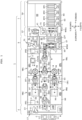
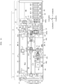
- FIG. 1 is a plan view of a substrate treatment system 1 according to a first embodiment.
- FIG. 2 is a left side view of the substrate treatment system 1 according to the first embodiment.
- the substrate treatment system 1 includes a stocker device 2, a single-wafer treatment device 3, an interface device 5, a batch treatment device 7, and a carrier transport mechanism 9.
- the stocker device 2, the single-wafer treatment device 3, the interface device 5, and the batch treatment device 7 are disposed in a line and linearly in this order.
- FIG. 1 will be referred to.
- a substrate treatment system 1 performs treatment on a substrate W.
- the substrate treatment system 1 performs, for example, chemical liquid treatment, washing treatment, drying treatment, and the like on the substrate W.
- the substrate treatment system 1 adopts a treatment method (so-called hybrid method) having both a batch type and a single-wafer type.
- the batch type is a method of collectively performing treatment on a plurality of substrates W in a vertical posture.
- the single-wafer type is a method of performing treatment on the substrates W one by one in a horizontal posture.
- a direction in which the stocker device 2, the single-wafer treatment device 3, the interface device 5, and the batch treatment device 7 are arranged will be referred to as a "front-rear direction X".
- the front-rear direction X is horizontal.
- a direction from the batch treatment device 7 toward the stocker device 2 will be referred to as a "front side”.
- a direction opposite to the front will be referred to as a "rear side”.
- a horizontal direction orthogonal to the front-rear direction X will be referred to as a "width direction Y".
- One direction in the "width direction Y" will be referred to as a "right side” as appropriate.
- a direction opposite to the right side will be referred to as a "left side”.
- a direction perpendicular to the horizontal direction will be referred to as a "vertical direction Z”.
- front, rear, right, left, up, and down are illustrated for reference as appropriate.
- the stocker device 2 accommodates at least one carrier C.
- the carrier C stores a plurality of (for example, twenty-five) substrates W in a horizontal posture aligned in the vertical direction Z at predetermined intervals (for example, 10 mm).
- a front opening unify pod (FOUP) is used, but the carrier C is not limited thereto.
- the stocker device 2 includes a plurality of (for example, two) load ports 11 and a stocker body 13.
- the two load ports 11 are provided adjacent to the front side of the stocker body 13.
- Each of the two load ports 11 is used to load and unload the carrier C.
- the stocker body 13 includes a plurality of shelves 15A and 15B and a first transport robot 17.
- the shelf 15A is a shelf for storing the substrate W in the carrier C.
- the shelf 15B is a storage shelf.
- the shelf 15A is provided adjacent to the front side of the single-wafer treatment device 3.
- the shelf 15A corresponds to a first carrier placement shelf of the present invention.
- the first transport robot 17 transports the carrier C between the two load ports 11, the shelf 15A, the shelf 15B, and the placement table 23 moved to a predetermined position on the stocker device 2 side.
- the first transport robot 17 includes a grip portion (gripper) 19 and a movement portion 21.
- the grip portion 19 grips the protrusion of the carrier C, for example.
- the movement portion 21 moves the grip portion 19 in the vertical direction Z and the horizontal direction (the front-rear direction X and the width direction Y).
- Each of the grip portion 19 and the movement portion 21 is driven by one or more electric motors.
- FIGS. 1 and 2 will be referred to.
- the carrier transport mechanism 9 is provided above the single-wafer treatment device 3 to overlap a part or the whole of the single-wafer treatment device 3 in a plan view.
- the carrier transport mechanism 9 transports the carrier C between a stocker device side position PT1 on the stocker device 2 side and an interface device side position PT2 on the interface device 5 side.
- the stocker device side position PT1 is a position where the carrier C is delivered between the first transport robot 17 and the carrier transport mechanism 9.
- the interface device side position PT2 is a position where the carrier C is delivered between the carrier transport mechanism 9 and the second transport robot 31 (described later).
- the carrier transport mechanism 9 includes a placement table 23 and a table movement portion 25.
- the carrier C is placed on the placement table 23.
- the table movement portion 25 moves the placement table 23 on which the carrier C is placed in parallel to the rear side (front-rear direction X).
- the table movement portion 25 is provided on, for example, a side wall 27 provided on the single-wafer treatment device 3 and extending in the front-rear direction X (see FIG. 5 ).
- the table movement portion 25 includes, for example, an electric motor, a guide rail, and a slider.
- the table movement portion 25 includes a screw shaft or a rack and a pinion.
- Interface device carrier movement region
- the interface device 5 is provided adjacent to the rear side of the single-wafer treatment device 3.
- the interface device 5 includes a carrier movement region R1 and a posture turning region R2.
- the carrier movement region R1 and the posture turning region R2 are disposed in the width direction Y.
- the carrier movement region R1 is disposed on the right side of the posture turning region R2.
- the carrier movement region R1 includes a shelf 29 and a second transport robot 31.
- the shelf 29 is provided adjacent to the front side of the batch treatment device 7 and the transfer block 37.
- the carrier C is placed on the shelf 29.
- the second transport robot 31 transports the carrier C between the placement table 23 moved to a predetermined position on the interface device 5 side and the shelf 29.
- the second transport robot 31 includes a grip portion (gripper) 33 and a movement portion 35.
- the grip portion 33 grips, for example, a protrusion on the upper surface of the carrier C.
- the movement portion 35 moves the grip portion 33 in the vertical direction Z and the horizontal direction (at least the front-rear direction X).
- the movement portion 35 is driven by an electric motor.
- the grip portion 33 is driven by an electric motor.
- the batch treatment device 7 collectively performs treatment on a plurality of (for example, twenty-five or fifty) substrates W. More specifically, the batch treatment device 7 takes out a plurality of (for example, twenty-five) substrates W from the carrier C transported to the shelf 29. Then, the batch treatment device 7 turns the plurality of (for example, twenty-five or fifty) taken-out substrates W from a horizontal posture to a vertical posture by using the first posture turning mechanism 41. The batch treatment device 7 performs predetermined batch treatment on a plurality of (for example, twenty-five or fifty) substrates W turned into the vertical posture. The batch treatment device 7 transports the plurality of substrates W subjected to the batch treatment to the interface device 5.
- the batch treatment device 7 includes a transfer block 37 and a treatment block 39.
- the transfer block 37 is provided adjacent to the rear side of the interface device 5.
- the transfer block 37 is provided adjacent to the rear side of the shelf 29.
- the treatment block 39 is adjacent to the transfer block 37 on the rear side. In other words, the treatment block 39 is provided adjacent to the rear side of the transfer block 37.
- the transfer block 37 includes a substrate handling mechanism (robot) HTR and a first posture turning mechanism 41.
- the substrate handling mechanism HTR is provided on the rear side of the shelf 29.
- the substrate handling mechanism HTR collectively takes out a plurality of (for example, twenty-five) substrates W from the carrier C placed on the shelf 29, and transports the taken-out substrates W to the first posture turning mechanism 41 in a horizontal posture.
- FIGS. 3A to 3C is a side view for describing the substrate handling mechanism HTR and the first posture turning mechanism 41.
- the substrate handling mechanism HTR includes a plurality of (for example, twenty-five) hands 43. Each hand 43 holds one substrate W.
- the substrate handling mechanism HTR includes three hands 43.
- a pair of horizontal holding portions 51B and a pair of vertical holding portions 51C that will be described later hold three substrates W.
- a pusher 53A that will be described later supports six substrates W.
- the substrate handling mechanism HTR includes a hand support portion 45, an advance/retract portion 47, and an elevation rotation portion 49.
- the hand support portion 45 supports the plurality of hands 43.
- the advance/retract portion 47 advances and retracts the plurality of hands 43 via the hand support portion 45.
- the elevation rotation portion 49 lifts and lowers the plurality of hands 43 and the advance/retract portion 47.
- the elevation rotation portion 49 rotates the advance/retract portion 47 about a vertical axis AX1 to change an orientation of the hand 43.
- the elevation rotation portion 49 is fixed to the floor surface and does not move in the horizontal direction (the front-rear direction X and the width direction Y).
- the advance/retract portion 47 and the elevation rotation portion 49 each include an electric motor.
- the substrate handling mechanism HTR may include a hand (not illustrated) for transporting only one substrate W, separately from the hand 43.
- the first posture turning mechanism 41 turns a plurality of (for example, twenty-five) substrates W transported by the substrate handling mechanism HTR from a horizontal posture to a vertical posture.
- the first posture turning mechanism 41 includes a posture turning unit 51 and a pusher mechanism 53.
- the substrate handling mechanism HTR, the posture turning unit 51, and the pusher mechanism 53 are disposed on the left side in this order.
- the first posture turning mechanism 41 (including a pusher 53A that will be described later) is provided between the substrate handling mechanism HTR and a batch substrate transport region R4 (described later).
- the posture turning unit 51 includes a support base 51A, a pair of horizontal holding portions 51B, a pair of vertical holding portions 51C, and a rotation driving portion 51D.
- the pair of horizontal holding portions 51B and the pair of vertical holding portions 51C are provided on the support base 51A.
- the pair of horizontal holding portions 51B supports the substrates W from below while being in contact with the lower surfaces of the respective substrates W.
- the pair of vertical holding portions 51C holds the substrate W.
- the rotation driving portion 51D rotates the support base 51A about a horizontal axis AX2.
- the pusher mechanism 53 includes a pusher 53A, an elevation rotation portion 53B, a horizontal movement portion 53C, and a rail 53D.
- the pusher 53A holds a lower portion of each of a plurality of (for example, twenty-five or fifty) substrates W in a vertical posture.
- the pusher 53A holds the plurality of substrates W received from the substrate handling mechanism HTR in the vertical posture via the posture turning unit 51.
- the elevation rotation portion 53B lifts and lowers the pusher 53A in the vertical direction Z.
- the elevation rotation portion 53B rotates the pusher 53A about a vertical axis AX3.
- an orientation of the device surface of the substrate W indicated by an arrow AR1 may be set to any orientation.
- the horizontal movement portion 53C horizontally moves the pusher 53A and the elevation rotation portion 53B along the rail 53D.
- the rail 53D extends in the width direction Y.
- each of the rotation driving portion 51D, the elevation rotation portion 53B, and the horizontal movement portion 53C includes an electric motor.
- the posture turning unit 51 corresponds to a first posture turning unit of the present invention.
- the pusher 53A corresponds to a vertical holder of the present invention.
- each of four batch treatment tanks BT1 to BT4 that will be described later of the treatment block 39 collectively performs treatment on fifty substrates W corresponding to two carriers C. Therefore, the pusher 53A holds the fifty substrates W (W1, W2) while a posture of the fifty substrates W is turned twenty-five substrates at a time.
- the twenty-five substrates W1 will be referred to as a first substrate group as appropriate.
- the twenty-five substrates W2 will be referred to as a second substrate group as appropriate. In a case where the substrates W1 and W2 are not particularly distinguished, the substrate W1 and the substrate W2 are described as a substrate W.
- FIG. 3A will be referred to.
- the posture turning unit 51 receives twenty-five substrates W1 from the substrate handling mechanism HTR.
- the twenty-five substrates W1 are in a horizontal posture and aligned at a full pitch (for example, at intervals of 10 mm).
- the full pitch will also be referred to as a normal pitch.
- the device surface of each substrate W1 faces upward.
- the device surface of the substrate W is a surface on which an electronic circuit is formed, and will be referred to as a "front surface".
- a back surface of the substrate W is a surface on which no electronic circuit is formed.
- a surface on an opposite side to the device surface is the back surface.
- FIG. 3B will be referred to.
- the rotation driving portion 51D of the posture turning unit 51 rotates the pair of horizontal holding portions 51B and the like by 90 degrees about the horizontal axis AX2 to turn the twenty-five substrates W1 from the horizontal posture to the vertical posture.
- the pusher mechanism 53 lifts the pusher 53A to receive the twenty-five substrates W1 from the posture turning unit 51.
- the pusher mechanism 53 rotates the pusher 53A by 180 degrees about the vertical axis AX3.
- the orientation of the twenty-five substrates W1 is changed from the left side to the right side.
- the posture turning unit 51 receives twenty-five substrates W2 from the substrate handling mechanism HTR, and turns the twenty-five substrates W2 from the horizontal posture to the vertical posture. Thereafter, the pusher mechanism 53 lifts the pusher 53A holding the twenty-five substrates W1. As a result, the pusher 53A further receives the twenty-five substrates W2.
- FIG. 3C will be referred to.
- the pusher 53A holds the fifty substrates W (W1, W2).
- the fifty substrates W are aligned at a half pitch (for example, at intervals of 5 mm). Note that the half pitch is an interval half of the full pitch.
- the pusher mechanism 53 moves the pusher 53A holding the fifty substrates W to a substrate delivery position PP below a pair of chucks 61 and 62 of a batch transport mechanism WTR1 (described later) along the rail 53D.
- the treatment block 39 includes a batch treatment region R3.
- the batch treatment region R3 is adjacent to the rear side of the transfer block 37.
- the batch treatment region R3 includes, for example, four batch treatment tanks BT1 to BT4.
- the four batch treatment tanks BT1 to BT4 are disposed in a line in the direction (front-rear direction X) in which the batch treatment region R3 extends.
- Each of the four batch treatment tanks BT1 to BT4 collectively performs immersion treatment (batch treatment) on a plurality of (for example, twenty-five or fifty) substrates W.
- Each of the four batch treatment tanks BT1 to BT4 stores a treatment liquid (for example, a chemical liquid or pure water) for immersing the plurality of substrates W.
- the four batch treatment tanks BT1 to BT4 include, for example, two chemical liquid treatment tanks BT1 and BT3 and two water washing treatment tanks BT2 and BT4.
- the chemical liquid treatment tank BT1 and the water washing treatment tank BT2 configure one set
- the chemical liquid treatment tank BT3 and the water washing treatment tank BT4 configure the other set.
- a combination of a chemical liquid treatment tank and a water washing treatment tank is not limited to this example.
- the number of batch treatment tanks is not limited to four, and may be one or two or more.
- Each of the two chemical liquid treatment tanks BT1 and BT3 performs etching treatment by using a chemical liquid.
- a chemical liquid for example, a phosphoric acid is used.
- Each of the chemical liquid treatment tanks BT1 and BT3 stores a chemical liquid supplied from a chemical liquid ejection pipe (not illustrated).
- Each of the two water washing treatment tanks BT2 and BT4 performs pure water washing treatment of washing away the chemical liquid attached to the plurality of substrates W with pure water.
- pure water For example, deionized water (DIW) is used as pure water.
- DIW deionized water
- Each of the water washing treatment tanks BT2 and BT4 stores pure water supplied from a pure water ejection pipe (not illustrated).
- lifters LF1 to LF4 are provided in the four batch treatment tanks BT1 to BT4, respectively.
- the lifter LF1 holds the substrates W in a vertical posture aligned at a half pitch (for example, an interval of 5 mm) which is a predetermined interval.
- the lifter LF1 lifts and lowers the plurality of substrates W between a treatment position inside the batch treatment tank BT1 and a delivery position above the batch treatment tank BT1.
- the other three lifters LF2 to LF4 are configured similarly to the lifter LF1.
- the batch treatment device 7 further includes a batch substrate transport region R4.
- the batch substrate transport region R4 is adjacent to the left side of the batch treatment region R3.
- One end of the batch substrate transport region R4 extends to the inside of the interface device 5.
- the other end of the batch substrate transport region R4 extends to the rear side.
- the batch substrate transport region R4 includes a batch transport mechanism (robot) WTR1.
- the batch transport mechanism WTR1 transports a plurality of substrates W between the four batch treatment tanks BT1 to BT4, the substrate delivery position PP of the first posture turning mechanism 41, and a standby tank 69 (described later) of the second posture turning mechanism 67.
- the four batch treatment tanks BT1 to BT4, the substrate delivery position PP, the standby tank 69 (described later), and an underwater posture turning unit 71 (described later) are aligned in a line in the front-rear direction X. Therefore, the batch transport mechanism WTR1 transports the plurality of substrates W in a vertical posture in parallel to the rear side or the front-rear direction X.
- the batch transport mechanism WTR1 includes a pair of chucks 61 and 62 and a guide rail 63.
- Each of the chucks 61 and 62 includes, for example, fifty holding grooves for holding fifty substrates W.
- Each of the two chucks 61 and 62 extends parallel to the width direction Y ( FIG. 1 ) in a plan view.
- the batch transport mechanism WTR1 opens and closes the two chucks 61 and 62.
- the batch transport mechanism WTR1 moves the pair of chucks 61 and 62 along the guide rail 63.
- the batch transport mechanism WTR1 is driven by an electric motor.
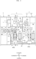
- FIG. 4 is a plan view for describing the interface device 5.
- FIG. 5 is a longitudinal cross-sectional view of the interface device 5 illustrated in FIG. 4 as viewed in a direction of an arrow A-A.
- FIGS. 6A to 6C , 7A to 7C , 8A, and 8B are diagrams for describing the second posture turning mechanism 67.
- the posture turning region R2 includes a housing 65 that blocks atmosphere from the carrier movement region R1 and the outside of the substrate treatment system 1.
- the interface device 5 includes two regions (the carrier movement region R1 and the posture turning region R2) having different atmospheres.
- the posture turning region R2 can ensure cleanliness more than the carrier movement region R1.
- the housing 65 includes two openings 65A and 65B that communicate with the transfer block 37 and a single-wafer transport region R5 (described later), respectively.
- the posture turning region R2 includes a second posture turning mechanism 67 and a direction turning belt conveyor 68.
- the housing 65 accommodates the second posture turning mechanism 67 and the direction turning belt conveyor 68.
- the second posture turning mechanism 67 turns a plurality of (for example, twenty-five or fifty) substrates W subjected to batch treatment in any of the four batch treatment tanks BT1 to BT4 from a vertical posture to a horizontal posture.
- the direction turning belt conveyor 68 receives one substrate W and transports the substrate W to the single-wafer treatment device 3.
- the direction turning belt conveyor 68 includes two pulleys 68A, two belts 68B, and an elevation rotation portion 68C.
- the two belts 68B are stretched around the two pulleys 68A.
- At least one of the two pulleys 68A is rotationally driven by an electric motor.
- the elevation rotation portion 68C lifts and lowers the two pulleys 68A and the two belts 68B, and rotates the two pulleys 68A and the two belts 68B about a vertical axis AX4.
- the elevation rotation portion 68C In order to change a transport direction of one substrate W on the two belts 68B, the elevation rotation portion 68C, for example, lifts and lowers the two pulleys 68A and the like to a height position that does not interfere with an underwater posture turning unit 71 (described later) and a belt conveyor 101 (described later), and then rotates the two pulleys 68A and the like about the vertical axis AX4.
- the second posture turning mechanism 67 includes a standby tank 69, a selective transport mechanism (robot) WTR2, and an underwater posture turning unit 71.
- the standby tank 69 is provided on the front side of the substrate delivery position PP.
- the standby tank 69 is provided with a lifter LF7.
- the lifter LF7 is configured similarly to the lifter LF1.
- the standby tank 69 stores pure water (for example, DIW) supplied from a pure water ejection pipe (not illustrated).
- the selective transport mechanism WTR2 includes a pair of chucks 73 and 74 and a guide rail 75.
- the pair of chucks 73 and 74 is opened and closed.
- Each of the chucks 73 and 74 includes, for example, twenty-five holding grooves and twenty-five passage grooves alternately disposed. Therefore, the selective transport mechanism WTR2 can extract one substrate group of the twenty-five substrates W1 and the twenty-five substrates W2 from the fifty substrates W in which the twenty-five substrates W1 and the twenty-five substrates W2 are alternately disposed.
- the selective transport mechanism WTR2 transports a plurality of (for example, twenty-five) selectively extracted substrates W between the standby tank 69 and the underwater posture turning unit 71.
- the pair of chucks 73 and 74 is moved along the guide rail 75 linearly extending in the front-rear direction X.
- the selective transport mechanism WTR2 can move the pair of chucks 73 and 74 in the width direction Y, for example.
- the underwater posture turning unit 71 is provided on the front side of the standby tank 69.
- the underwater posture turning unit 71 includes an in-tank carrier 77, a lifter LF8, a posture turning tank 79, a rotation mechanism 81, a pusher mechanism 83, and a horizontal pushing mechanism 85 (see FIG. 8B ).
- the in-tank carrier 77 can store a plurality of (for example, twenty-five) substrates W.
- the in-tank carrier 77 includes a gateway 77A and a back opening 77B.
- the gateway 77A is an opening through which the substrate W passes.
- the back opening 77B faces the gateway 77A.
- the back opening 77B is formed to have a width smaller than a diameter of the stored substrate W in the radial direction of the substrate W. Thus, the plurality of substrates W cannot pass through the back opening 77B.
- the lifter LF8 includes two carrier support portions 87 that support the in-tank carrier 77.
- the lifter LF8 lifts and lowers the two carrier support portions 87.
- the posture turning tank 79 accommodates the in-tank carrier 77, the two carrier support portions 87 of the lifter LF8, and a pusher 83A (described later).
- the posture turning tank 79 stores pure water (for example, DIW) supplied from a pure water ejection pipe (not illustrated). As a result, the in-tank carrier 77 can be immersed in the pure water in the posture turning tank 79.
- the second posture turning mechanism 67 corresponds to a posture turning mechanism of the present invention.
- the underwater posture turning unit 71 corresponds to a second posture turning unit of the present invention.
- the second posture turning unit may be an articulated robot that turns the substrate W from a vertical posture to a horizontal posture instead of the underwater posture turning unit 71.
- the articulated robot includes a movable hand (not illustrated) that holds one substrate W.
- the rotation mechanism 81 includes two shafts 81A facing each other. Each of the two shafts 81A penetrates through the posture turning tank 79. The rotation mechanism 81 holds the in-tank carrier 77 by sandwiching the in-tank carrier 77 between the two shafts 81A. Further, the rotation mechanism 81 can rotate the in-tank carrier 77 held by the two shafts 81A about a horizontal axis AX5 of the shaft 81A.
- the pusher mechanism 83 includes a pusher 83A that holds lower portions of a plurality of (for example, twenty-five) substrates W in a vertical posture.
- the pusher mechanism 83 can lift and lower the pusher 83A and rotate the pusher around a vertical axis AX6 (see FIG. 6B ).
- the horizontal pushing mechanism 85 includes a pushing member 85A that pushes one substrate W in a horizontal posture (see FIG. 8B ).
- the pushing member 85A is moved to the right side while passing through the back opening 77B and the gateway 77A when the gateway 77A of the in-tank carrier 77 faces the right side.
- the lifter LF8, the rotation mechanism 81, the pusher mechanism 83, and the horizontal pushing mechanism 85 are each driven by at least one of an electric motor and an air cylinder.
- FIG. 6A Fifty substrates W held in a vertical posture by the lifter LF7 are immersed in pure water in the standby tank 69. As illustrated in FIG. 3C , in the fifty substrates W, twenty-five substrates W1 and twenty-five substrates W2 are alternately disposed.
- the selective transport mechanism WTR2 is moved to above the standby tank 69.
- the lifter LF7 pulls up the fifty substrates W from the pure water in the standby tank 69. Thereafter, the selective transport mechanism WTR2 receives the twenty-five substrates W1 out of the fifty substrates W from the lifter LF7 by using the pair of chucks 73 and 74. Therefore, the twenty-five substrates W2 remain in the lifter LF7.
- the lifter LF7 immerses the twenty-five substrates W2 in the pure water in the standby tank 69.
- the selective transport mechanism WTR2 transports the twenty-five substrates W1 to above the posture turning tank 79 and the pusher 83A.
- FIG. 6B will be referred to.
- the pusher mechanism 83 lifts the pusher 83A while allowing the pusher 83A to pass between the two carrier support portions 87 and through the back opening 77B and the gateway 77A of the in-tank carrier 77 with the gateway 77A facing upward.
- the pusher 83A holds the lower portions of the twenty-five substrates W1 held by the pair of chucks 73 and 74.
- the selective transport mechanism WTR2 opens the pair of chucks 73 and 74.
- the pusher 83A receives the twenty-five substrates W1 from the selective transport mechanism WTR2.
- the selective transport mechanism WTR2 is moved from above the pusher 83A.
- the pusher mechanism 83 adjusts the orientation of the twenty-five substrates W1 by rotating the twenty-five substrates W1 about a vertical axis AX6 such that the device surfaces face upward when the twenty-five substrates W1 are turned into a horizontal posture.
- FIG. 6C will be referred to.
- the lifter LF8 lifts the two carrier support portions 87 supporting the in-tank carrier 77 with the gateway 77A facing upward from a position P1 to a position P2.
- the position P2 is a position pulled up from the pure water in the in-tank carrier 77.
- FIG. 7A will be referred to.
- the pusher mechanism 83 lowers the pusher 83A to the bottom surface in the posture turning tank 79.
- the lifter LF8 lowers the two carrier support portions 87 from the position P2 to the position P1.
- the twenty-five substrates W1 stored in the in-tank carrier 77 are immersed in pure water in the posture turning tank 79.
- FIG. 7B will be referred to.
- the rotation mechanism 81 holds the in-tank carrier 77 with the two shafts 81A.
- FIG. 7C will be referred to.
- the lifter LF8 lowers the two carrier support portions 87 from the position P1 to a position P3.
- the position P3 is a position near the bottom surface in the posture turning tank 79.
- the rotation mechanism 81 rotates the in-tank carrier 77 by 90 degrees about the horizontal axis AX5.
- the twenty-five substrates W1 in the in-tank carrier 77 are turned from the vertical posture to the horizontal posture. In this case, the device surface of each substrate W1 faces upward.
- FIG. 8A will be referred to.
- the lifter LF8 lifts the two carrier support portions 87 from the position P3 to a position P4.
- the two carrier support portions 87 come into contact with the lower surface of the in-tank carrier 77.
- the rotation mechanism 81 separates the two shafts 81A from the in-tank carrier 77.
- the in-tank carrier 77 is held by only the two carrier support portions 87.
- FIG. 8B will be referred to.
- the lifter LF8 lifts the two carrier support portions 87 such that the substrate W1 comes out of the pure water in the posture turning tank 79.
- the horizontal pushing mechanism 85 pushes one substrate W1 taken out from pure water by the pushing member 85A to the right side.
- the pushed substrate W1 is transported onto the two belts 68B of the direction turning belt conveyor 68.
- the direction turning belt conveyor 68 turns the transport direction of one substrate W1 from the right side to the front side.
- the direction turning belt conveyor 68 transports the one substrate W1 to a belt conveyor 101 (described later) of the single-wafer treatment device 3.
- the remaining twenty-five substrates W2 immersed in the pure water in the standby tank 69 are turned into a horizontal posture.
- the posture turning of the twenty-five substrates W2 is performed in the same manner as the posture turning of the twenty-five substrates W1 (see FIGS. 6A to 8B ).
- the single-wafer treatment device 3 performs predetermined single-wafer treatment on a plurality of (for example, twenty-five or fifty) substrates W received from the interface device 5 one by one.
- the single-wafer treatment device 3 transports the plurality of substrates W subjected to the single-wafer treatment to the carrier C transported to the shelf 15A.
- the single-wafer treatment device 3 is adjacent to the rear side of the stocker device 2 and is adjacent to the front side of the interface device 5.
- the single-wafer treatment device 3 includes a single-wafer transport region R5, a first single-wafer treatment region R6, and a second single-wafer treatment region R7.
- Each of the three regions R5, R6, and R7 is provided to extend the rear side or in the front-rear direction X.
- the second single-wafer treatment region R7, the single-wafer transport region R5, and the first single-wafer treatment region R6 are disposed side by side in this order on the left side which is the horizontal direction orthogonal to the rear side. That is, the first single-wafer treatment region R6 is adjacent to the left side of the single-wafer transport region R5.
- the second single-wafer treatment region R7 is adjacent to the right side of the single-wafer transport region R5.
- the rear side corresponds to a first direction of the present invention.
- the left side corresponds to a second direction of the present invention.
- the first single-wafer treatment region R6 includes a rear tower TW1, a front tower TW2, and a substrate transport robot CR1.
- the front tower TW2, the substrate transport robot CR1, and the rear tower TW1 are disposed in this order along the single-wafer transport region R5.
- the rear tower TW1 is disposed on the rear side of the substrate transport robot CR1.
- the front tower TW2 is disposed on the front side of the substrate transport robot CR1.
- the rear tower TW1 includes one first single-wafer treatment chamber SW1 and two second single-wafer treatment chambers SW2 stacked in the vertical direction Z.
- the front tower TW2 includes three second single-wafer treatment chambers SW2 stacked in the vertical direction Z. That is, the first single-wafer treatment region R6 includes a total of six single-wafer treatment chambers (the first single-wafer treatment chamber SW1 and the second single-wafer treatment chambers SW2) .
- the substrate transport robot CR1 includes a hand 91, an advance/retract portion 92, and an elevation rotation portion 93.
- the hand 91 holds one substrate W.
- the advance/retract portion 92 advances and retracts the hand 91.
- the elevation rotation portion 93 lifts and lowers the hand 91 and the advance/retract portion 92.
- the elevation rotation portion 93 rotates the hand 91 and the advance/retract portion 92 about a vertical axis AX7 to change an orientation of the hand 91.
- the elevation rotation portion 93 is fixed to a floor surface, and the elevation rotation portion 93 does not move in the horizontal direction.
- the second single-wafer treatment region R7 includes a rear tower TW1, a front tower TW2, and a substrate transport robot CR2. That is, the second single-wafer treatment region R7 includes six single-wafer treatment chambers (a first single-wafer treatment chamber SW1 and second single-wafer treatment chambers SW2).
- the substrate transport robot CR2 is configured similarly to the substrate transport robot CR1. The type and number of single-wafer treatment chambers included in the rear tower TW1 and the front tower TW2 are set as appropriate.
- the first single-wafer treatment chamber SW1 includes, for example, a holding rotation unit 94 and a nozzle 95.
- the holding rotation unit 94 includes a spin chuck that holds one substrate W in a horizontal posture and an electric motor that rotates the spin chuck about a vertical axis passing through the center of the substrate W.
- the nozzle 95 supplies a treatment solution onto the substrate W held by the holding rotation unit 94.
- the treatment solution for example, pure water (for example, DIW) and isopropyl alcohol (IPA) are used.
- the first single-wafer treatment chamber SW1 performs, for example, washing treatment on the substrate W with pure water, and then forms a liquid film of IPA on the upper surface of the substrate W.
- Each of the second single-wafer treatment chambers SW2 performs, for example, drying treatment with a supercritical fluid.
- a supercritical fluid for example, carbon dioxide is used as the fluid.
- the fluid is carbon dioxide
- a supercritical state is obtained when the critical temperature is 31°C and the critical pressure is 7.38 MPa.
- the second single-wafer treatment chamber SW2 includes a chamber body (container) 96, a support tray 97, and a lid portion.
- the chamber body 96 includes a treatment space provided inside, an opening for inserting the substrate W into the treatment space, a supply port, and an exhaust port.
- the substrate W is accommodated in the treatment space while being supported by the support tray 97.
- the lid portion closes the opening of the chamber body 96.
- each of the second single-wafer treatment chambers SW2 brings the fluid into the supercritical state, and supplies the supercritical fluid from the supply port to the treatment space in the chamber body 96.
- the drying treatment is performed on one substrate W by using the supercritical fluid supplied to the treatment space.
- the belt conveyor 101 includes two pulleys 103, two belts 105, and a pin lifting/lowering unit 107 (see FIG. 4 ).
- the two belts 105 are stretched around the two pulleys 103.
- the pin lifting/lowering unit 107 is provided at the front portion of the belt conveyor 101.
- the pin lifting/lowering unit 107 has three lift pins PN, and lifts one substrate W on the two belts 105 by using the three lift pins PN.
- At least one of the two pulleys 103 and the pin lifting/lowering unit 107 are each driven by an electric motor.
- Each of the four substrate transport robots CR3 to CR6 is configured similarly to the substrate transport robot CR1.
- the substrate transport robot CR4 preferably includes two hands 91.
- the first hand 91 is used to transport the wet substrate W
- the second hand 91 is used to transport the substrate W dried in the second single-wafer treatment chamber SW2.
- Each of the three substrate placement portions PS1 to PS3 is configured to place one or two or more substrates W thereon.
- the belt conveyor 101, the substrate transport robot CR3, the substrate transport robot CR4, the substrate transport robot CR5, and the substrate transport robot CR6 are disposed to face the front side in this order.
- the substrate placement portion PS1 is disposed between the two substrate transport robots CR3 and CR4.
- the substrate placement portion PS2 is disposed between the two substrate transport robots CR4 and CR5.
- the substrate placement portion PS3 is disposed between the two substrate transport robots CR5 and CR6.
- the belt conveyor 101 extends to the rear side up to the direction turning belt conveyor 68 of the interface device 5.
- the belt conveyor 101 receives the substrate W from the second posture turning mechanism 67 via the direction turning belt conveyor 68.
- the belt conveyor 101 moves the substrate W to above the pin lifting/lowering unit 107 through belt transport.
- the substrate transport robot CR3 transports the substrate W between the pin lifting/lowering unit 107 of the belt conveyor 101 and the substrate placement portion PS1.
- the substrate transport robot CR4 transports the substrates W between the two substrate placement portions PS1 and PS2 and the six single-wafer treatment chambers (the first single-wafer treatment chamber SW1 and the second single-wafer treatment chambers SW2) of the two rear towers TW1.
- the substrate transport robot CR5 transports the substrate W between the two substrate placement portions PS2 and PS3 and the six second single-wafer treatment chambers SW2 of the two front towers TW2.
- the substrate transport robot CR6 transports the substrate W between the substrate placement portion PS3 and the carrier C placed on the shelf 15A.
- the substrate treatment system 1 includes a control unit 110 (see FIG. 1 ) and a storage unit (not illustrated).
- the control unit 110 controls each constituent of the substrate treatment system 1.
- the control unit 110 includes one or more processors such as a central processing unit (CPU).
- the storage unit includes, for example, at least one of a read-only memory (ROM), a random-access memory (RAM), and a hard disk.
- the storage unit stores a computer program necessary for controlling each constituent of the substrate treatment system 1.
- FIG. 1 will be referred to.
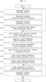
- An external transport robot (not illustrated) transports two carriers C to the load port 11.
- the first transport robot 17 of the stocker device 2 does not transport the first carrier C to the shelf 15A that can be accessed by the substrate transport robot CR6 of the single-wafer treatment device 3. This is because there is a possibility that the throughput of the substrate treatment system 1 decreases due to the substrate W passing through the single-wafer treatment device 3. Instead, the carrier C is transported from the stocker device 2 to the interface device 5 adjacent to the batch treatment device 7 in a state in which the substrate W before treatment (untreated) is stored.
- the first transport robot 17 of the stocker device 2 transports the first carrier C placed on the load port 11 to the stocker device side position PT1.
- the carrier transport mechanism 9 uses the placement table 23 to receive the first carrier C transported to the stocker device side position PT1 from the first transport robot 17.
- the carrier transport mechanism 9 transports the first carrier C from the stocker device side position PT1 to the interface device side position PT2 by moving the placement table 23 to the rear side.
- the second transport robot 31 of the interface device 5 transports the first carrier C from the interface device side position PT2 to the shelf 29. That is, the second transport robot 31 grips the first carrier C on the placement table 23 and transports the gripped first carrier C to the shelf 29.
- the substrate handling mechanism HTR of the transfer block 37 of the batch treatment device 7 takes out the twenty-five substrates W1 (first substrate group) from the first carrier C transported to the shelf 29, and transports the twenty-five substrates W1 to the posture turning unit 51.
- the second transport robot 31 of the interface device 5 transports the first carrier C (empty carrier) from which the twenty-five substrates W1 have been taken out from the shelf 29 to the interface device side position PT2.
- the carrier transport mechanism 9 receives the first carrier C by using the placement table 23.
- the carrier transport mechanism 9 transports the first carrier C (empty carrier) from the interface device side position PT2 to the stocker device side position PT1 by moving the placement table 23 to the front side.
- the first transport robot 17 of the stocker device 2 transports the first carrier C (empty carrier) from the stocker device side position PT1 to the shelf 15A. That is, the first transport robot 17 grips the first carrier C on the placement table 23 and transports the gripped first carrier C to the shelf 15A.
- steps S01 to S04 are performed on the second carrier C. That is, the first transport robot 17 transports the second carrier C placed on the load port 11 to the stocker device side position PT1.
- the carrier transport mechanism 9 receives the second carrier C by using the placement table 23.
- the carrier transport mechanism 9 transports the second carrier C from the stocker device side position PT1 to the interface device side position PT2 by moving the placement table 23 to the rear side.
- the second transport robot 31 grips the second carrier C on the placement table 23 and transports the gripped second carrier C from the interface device side position PT2 to the shelf 29.
- the substrate handling mechanism HTR of the batch treatment device 7 takes out the twenty-five substrates W2 (second substrate group) from the second carrier C transported to the shelf 29, and transports the twenty-five substrates W2 to the posture turning unit 51.
- the second transport robot 31 transports the second carrier C (empty carrier) from which the twenty-five substrates W2 have been taken out to the interface device side position PT2 from the shelf 29.
- the carrier transport mechanism 9 uses the placement table 23 to receive the second carrier C (empty carrier) from the second transport robot 31.
- the carrier transport mechanism 9 transports the second carrier C (empty carrier) from the interface device side position PT2 to the stocker device side position PT1 by moving the placement table 23 to the front side.
- the first transport robot 17 grips the second carrier C on the placement table 23 and transports the gripped second carrier C from the stocker device side position PT1 to the storage shelf 15B.
- the second carrier C (empty carrier) is stored on the shelf 15B until the second carrier C can be transported to the shelf 15A.
- the posture turning unit 51 individually turns the twenty-five substrates W1 and the twenty-five substrates W2 from a horizontal posture to a vertical posture.
- the pusher 53A of the pusher mechanism 53 holds the fifty substrates W (substrates W1 and W2) in which the twenty-five substrates W1 and the twenty-five substrates W2 are alternately disposed in a vertical posture. Thereafter, the pusher mechanism 53 transports the fifty substrates W to the substrate delivery position PP.
- the batch transport mechanism WTR1 receives the fifty substrates W in a vertical posture from the pusher mechanism 53 at the substrate delivery position PP, and transports the fifty substrates W to one of the two lifters LF1 and LF3 of the two chemical liquid treatment tanks BT1 and BT3.
- the batch transport mechanism WTR1 transports the fifty substrates W to the lifter LF1 of the chemical liquid treatment tank BT1.
- the lifter LF1 receives the fifty substrates W at a position above the chemical liquid treatment tank BT1.
- the lifter LF1 immerses the fifty substrates W in a chemical liquid (for example, phosphoric acid) in the chemical liquid treatment tank BT1.
- etching treatment (batch treatment) is performed.
- the lifter LF1 pulls up the fifty substrates W from the phosphoric acid in the chemical liquid treatment tank BT1.
- the same treatment as in the chemical liquid treatment tank BT1 is performed.
- the batch transport mechanism WTR1 receives, for example, the fifty substrates W in a vertical posture from the lifter LF1, and transports the fifty substrates W to the lifter LF2 of the water washing treatment tank BT2.
- the lifter LF2 receives the fifty substrates W at a position above the water washing treatment tank BT2.
- the lifter LF2 immerses the fifty substrates W in pure water in the water washing treatment tank BT2. Accordingly, washing treatment (batch treatment) is performed.
- the batch transport mechanism WTR1 In a case where the batch transport mechanism WTR1 receives the fifty substrates W in the vertical posture from the lifter LF3, the batch transport mechanism WTR1 transports the fifty substrates W to the lifter LF4 of the water washing treatment tank BT4.
- the lifter LF4 immerses the fifty substrates W in pure water in the water washing treatment tank BT4.
- the batch transport mechanism WTR1 receives the fifty substrates W subjected to the pure water washing treatment from one of the two lifters LF2 and LF4.
- the lifter LF2 pulls up the fifty substrates W from the pure water in the water washing treatment tank BT2.
- the batch transport mechanism WTR1 transports the received fifty substrates W to the lifter LF7 of the standby tank 69 of the interface device 5 across the substrate delivery position PP of the first posture turning mechanism 41.
- the lifter LF7 receives the fifty substrates W at a position above the standby tank 69.
- the underwater posture turning unit 71 individually turns the twenty-five substrates W1 and the twenty-five substrates W2 from a vertical posture to a horizontal posture.
- the underwater posture turning unit 71 transports the twenty-five substrates W1 (the twenty-five substrates W2) turned into the horizontal posture one by one to the direction turning belt conveyor 68.
- the direction turning belt conveyor 68 turns a transport direction of one substrate W from the right side to the front side, and transports the transported one substrate W to the belt conveyor 101 of the single-wafer treatment device 3.
- the belt conveyor 101 transports one substrate W to the pin lifting/lowering unit 107.
- the pin lifting/lowering unit 107 lifts the one substrate W from the two belts 105.
- the substrate transport robot CR3 receives one substrate W from the pin lifting/lowering unit 107, and transports the one substrate W to the substrate placement portion PS1 in a horizontal posture. Thereafter, the substrate transport robot CR4 uses the first hand 91 out of the two hands 91 to receive one wet substrate W from the substrate placement portion PS1. Then, the substrate transport robot CR4 transports the substrate W received by the first hand 91 to one of the two first single-wafer treatment chambers SW1 of the two rear towers TW1.
- Each of the first single-wafer treatment chambers SW1 holds and rotates the substrate W with the device surface facing upward by the holding rotation unit 94, and supplies pure water from the nozzle 95 to the device surface. Thereafter, each first single-wafer treatment chamber SW1 supplies IPA from the nozzle 95 to the device surface (upper surface) of the substrate W, and replaces the pure water of the substrate W with IPA.
- the substrate transport robot CR1 transports the substrate W subjected to replacement with IPA from the first single-wafer treatment chamber SW1 of the first single-wafer treatment region R6 to any one of the five second single-wafer treatment chambers SW2 of the first single-wafer treatment region R6.
- the substrate W is subjected to treatment in the first single-wafer treatment chamber SW1 of the second single-wafer treatment region R7.
- the second substrate transport robot CR2 transports the substrate W subjected to replacement with IPA from the first single-wafer treatment chamber SW1 of the second single-wafer treatment region R7 to any one of the five second single-wafer treatment chambers SW2 of the second single-wafer treatment region R7.
- Each of the second single-wafer treatment chambers SW2 performs drying treatment on one substrate W with carbon dioxide (supercritical fluid) in a supercritical state.
- the pattern collapse of a pattern surface (device surface) of the substrate W is curbed due to the drying treatment using the supercritical fluid.
- drying treatment is performed in any one of the six second single-wafer treatment chambers SW2 of the two front towers TW2 of the two single-wafer treatment regions R6 and R7.
- the substrate transport robot CR5 transports one substrate W subjected to the drying treatment from the second single-wafer treatment chamber SW2 subjected to the drying treatment to the substrate placement portion PS3.
- the drying treatment is performed in any one of the four second single-wafer treatment chambers SW2 of the two rear towers TW1 of the two single-wafer treatment regions R6 and R7.
- the substrate transport robot CR4 uses the second hand 91 out of the two hands 91 to receive one substrate W from the second single-wafer treatment chamber SW2 subjected to the drying treatment. Then, the substrate transport robot CR4 transports the substrate W received by the second hand 91 to the substrate placement portion PS2. Thereafter, the substrate transport robot CR5 transports the substrate W subjected to the drying treatment from the substrate placement portion PS2 to the substrate placement portion PS3.
- the substrate transport robot CR6 transports the substrate W1 from the substrate placement portion PS3 to the first carrier C placed on the shelf 15A.
- the first transport robot 17 transports the first carrier C from the shelf 15A to one of the two load ports 11. In addition, the first transport robot 17 transports the second carrier C (empty carrier) from the shelf 15B to the shelf 15A after the first carrier C is transported.
- the substrate transport robot CR6 transports the substrate W2 from the substrate placement portion PS3 to the second carrier C placed on the shelf 15A.
- the first transport robot 17 transports the second carrier C from the shelf 15A to one of the two load ports 11.
- An external transport mechanism (not illustrated) sequentially transports the two carriers C from the load port 11 to the next destination.
- the stocker device 2, the single-wafer treatment device 3, the interface device 5, and the batch treatment device 7 are disposed in a line and linearly in this order.
- the carrier transport mechanism 9 transports the carrier C between the stocker device side position PT1 on the stocker device 2 side and the interface device side position PT2 on the interface device 5 side. Therefore, the substrate W can be transported from the stocker device 2 to the interface device 5 in units of carriers. Thus, it is possible to prevent a decrease in throughput due to the substrate W passing through the single-wafer treatment device 3.
- the substrate W is stored in the carrier C, it is possible to prevent particles from adhering to the substrate W when the substrate W is transported from the stocker device 2 to the interface device 5.
- the batch treatment device 7 includes the posture turning unit 51.
- the interface device 5 includes the underwater posture turning unit 71.
- the batch treatment device 7 can perform predetermined batch treatment on a plurality of substrates W turned into a vertical posture.
- the single-wafer treatment device 3 can perform predetermined single-wafer treatment on a plurality of substrates W turned into a horizontal posture in the interface device 5 one by one.
- the batch treatment device 7 includes the transfer block 37 adjacent to the shelf 29 and the treatment block 39 adjacent to the transfer block 37. Such a disposition is similar to that of a general batch-type substrate treatment device.
- posture turning is generally performed in the transfer block 37 including the substrate handling mechanism HTR.
- one end of the batch substrate transport region R4 extends to the inside of the interface device 5, and the other end of the batch substrate transport region R4 extends to the rear side.
- the batch transport mechanism WTR1 of the batch substrate transport region R4 transports the plurality of substrates W from, for example, the two batch treatment tanks BT2 and BT4 (treatment block 39) to the second posture turning mechanism 67 (interface device 5) in a vertical posture while exceeding the first posture turning mechanism 41 (transfer block 37). Therefore, the plurality of substrates W can be efficiently transported.
- the carrier transport mechanism 9 is provided above the single-wafer treatment device 3 to overlap the single-wafer treatment device 3 in a plan view.
- the single-wafer treatment device 3 can increase a region in which the single-wafer treatment is performed. That is, the single-wafer treatment device 3 can include more single-wafer treatment chambers (the first single-wafer treatment chamber SW1 and the second single-wafer treatment chambers SW2). Therefore, the throughput can be improved.
- FIG. 10 is a plan view of a substrate treatment system 1 according to the second embodiment.
- the rear towers TW1, the front towers TW2, and the six substrate transport robots CR1 to CR6 are hidden by a ceiling wall 115.
- the substrate treatment system 1 of the first embodiment includes the single carrier transport mechanism 9.
- the substrate treatment system 1 of the second embodiment may include a plurality of (for example, two) carrier transport mechanisms 9A and 9B.
- the two carrier transport mechanisms 9A and 9B are disposed side by side in the width direction Y. Each of the two carrier transport mechanisms 9A and 9B is provided above the single-wafer treatment device 3 to overlap a part or the whole of the single-wafer treatment device 3 in a plan view. Each of the two carrier transport mechanisms 9A and 9B is configured similarly to the carrier transport mechanism 9 of the first embodiment. That is, the first carrier transport mechanism 9A includes the placement table 23A and the table movement portion 25A. Similarly, the second carrier transport mechanism 9B includes the placement table 23B and the table movement portion 25B.
- the first carrier transport mechanism 9A transports the carrier C between the stocker device side position PT1 on the stocker device 2 side and the interface device side position PT2 on the interface device 5 side.
- the second carrier transport mechanism 9B transports the carrier C between the stocker device side position PT3 on the stocker device 2 side and the interface device side position PT4 on the interface device 5 side.
- the two carrier transport mechanisms 9A and 9B correspond to a carrier transport mechanism and a second carrier transport mechanism of the present invention.
- the first transport robot 17 transports the carrier C to the placement table 23A moved to a predetermined position on the stocker device 2 side. Similarly, the first transport robot 17 transports the carrier C to the placement table 23B moved to a predetermined position on the stocker device 2 side.
- the second transport robot 31 transports the carrier C to the placement table 23A moved to a predetermined position on the interface device 5 side. Similarly, the second transport robot 31 transports the carrier C to the placement table 23B moved to a predetermined position on the interface device 5 side.
- the first carrier transport mechanism 9A transports the first carrier C storing the substrate W before treatment from the stocker device side position PT1 to the interface device side position PT2. In addition, the first carrier transport mechanism 9A transports the empty first carrier C from the interface device side position PT2 to the stocker device side position PT1. Note that "before treatment” indicates that any treatment is not performed in the substrate treatment system 1.
- the second carrier transport mechanism 9B transports the second carrier C storing the substrate W before treatment from the stocker device side position PT3 to the interface device side position PT4. In addition, the second carrier transport mechanism 9B transports the empty second carrier C from the interface device side position PT4 to the stocker device side position PT3.
- the first carrier transport mechanism 9A may transport only the carrier C storing the substrate W before treatment.
- the second carrier transport mechanism 9B may transport only the empty carrier C.
- the substrate treatment system 1 of the present embodiment includes a plurality of (for example, two) carrier transport mechanisms 9A and 9B. Since the number of carrier transport mechanisms 9 is increased, the carrier C can be efficiently transported between the stocker device 2 and the interface device 5.
- FIG. 11 is a plan view of a substrate treatment system 1 according to the third embodiment.
- FIG. 12 is a longitudinal cross-sectional view of a single-wafer treatment device 3 illustrated in FIG. 11 as viewed in a direction of an arrow B-B.
- the single-wafer treatment device 3 includes the second single-wafer treatment region R7, the single-wafer transport region R5, and the first single-wafer treatment region R6.
- the single-wafer treatment device 3 of the third embodiment includes a carrier transport region R11, a single-wafer transport region R5, and a first single-wafer treatment region R6.
- Each of the carrier transport region R11, the single-wafer transport region R5, and the first single-wafer treatment region R6 is provided to extend to the rear side or in the front-rear direction X.
- the carrier transport region R11, the single-wafer transport region R5, and the first single-wafer treatment region R6 are disposed side by side in this order on the left side which is a horizontal direction orthogonal to the rear side.
- the carrier transport region R11 is provided adjacent to the right side of the single-wafer transport region R5.
- the first single-wafer treatment region R6 is provided adjacent to the left side of the single-wafer transport region R5.
- a wall 121 is a wall that blocks an atmosphere between the carrier transport region R11 and the single-wafer transport region R5.
- the carrier transport region R11 includes a carrier transport mechanism 9.
- the carrier transport region R11 may include a plurality of carrier transport mechanisms 9.
- the two carrier transport mechanisms 9 are disposed in the vertical direction Z.
- the second carrier transport mechanism 9 is disposed, for example, at a position indicated by a dashed line HA.
- the single-wafer transport region R5 includes a substrate transport robot CR7 and a belt conveyor 101.
- the substrate transport robot CR7 and the belt conveyor 101 transport at least one substrate W between the interface device 5, the six single-wafer treatment chambers (the first single-wafer treatment chamber SW1 and the second single-wafer treatment chambers SW2), and the carrier C transported to the shelf 15A.
- the substrate transport robot CR7 includes a hand 91, an advance/retract portion 92, and an elevation rotation portion 93.
- the substrate transport robot CR7 further includes a guide rail 123 extending in the front-rear direction X.
- the substrate transport robot CR7 (elevation rotation portion 93) is movable along the guide rail 123.
- the single-wafer treatment region R6 includes a rear tower TW1, a front tower TW2, and a substrate transport robot CR1.
- the rear tower TW1 includes one first single-wafer treatment chamber SW1 and two second single-wafer treatment chambers SW2 disposed in the vertical direction Z.
- the front tower TW2 includes three second single-wafer treatment chambers SW2 disposed in the vertical direction Z.
- the substrate transport robot CR7 includes, for example, two hands 91.
- the substrate transport robot CR7 uses the first hand 91 to transport one wet substrate W from the pin lifting/lowering unit 107 of the belt conveyor 101 to one first single-wafer treatment chamber SW1 of the rear tower TW1.
- the substrate transport robot CR1 of the single-wafer treatment region R6 transports one substrate W subjected to replacement with IPA from one first single-wafer treatment chamber SW1 to any one of five second single-wafer treatment chambers SW2.
- the substrate transport robot CR7 uses the second hand 91 to transport the one substrate W subjected to drying treatment from the second single-wafer treatment chamber SW2 in which the drying treatment has been performed to the carrier C placed on the shelf 15A.
- the carrier transport mechanism 9 is disposed above the single-wafer treatment device 3 (in the case of the first and second embodiments), it is necessary to transport the carrier transport mechanism 9 to above the single-wafer treatment device 3.
- the carrier transport region R11 including the carrier transport mechanism 9 is disposed on the side of the single-wafer transport region R5 and the single-wafer treatment region R6. Therefore, the load of carrying the carrier transport mechanism 9 can be reduced, and thus the assembly of the substrate treatment system 1 can be relatively facilitated.
- Each of the first transport robot 17 and the second transport robot 31 does not need to transport the carrier C to a position higher than the ceiling wall 115 of the single-wafer treatment device 3. Therefore, the carrier C can be efficiently transported between the stocker device 2 and the interface device 5.
- the carrier transport region R11, the single-wafer transport region R5, and the single-wafer treatment region R6 are disposed side by side in the horizontal direction (width direction Y), it is possible to curb an increase in a length of the substrate treatment system 1 in the width direction. That is, since the second single-wafer treatment region R7 illustrated in FIG. 1 is merely replaced with the carrier transport region R11, the length of the substrate treatment system 1 in the width direction Y is not substantially changed.
- FIG. 13 is a plan view of a substrate treatment system 1 according to the fourth embodiment. Note that, in FIG. 13 , a longitudinal cross-sectional view of the single-wafer treatment device 3 as viewed in the direction of the arrow B-B is substantially the same as FIG. 12 .
- the single-wafer treatment region R6 includes six single-wafer treatment chambers (the first single-wafer treatment chamber SW1 and the second single-wafer treatment chambers SW2).
- One first single-wafer treatment chamber SW1 performs treatment on one substrate W with pure water and IPA
- five second single-wafer treatment chambers SW2 each perform drying treatment on one substrate W with a supercritical fluid.
- the single-wafer treatment region R6 may include six first single-wafer treatment chambers SW1, and each of the six first single-wafer treatment chambers SW1 may perform treatment on one substrate W with pure water and IPA, and then perform spin drying.
- the single-wafer treatment device 3 includes a carrier transport region R11, a single-wafer transport region R5, and a single-wafer treatment region R6.
- Each of the carrier transport region R11, the single-wafer transport region R5, and the single-wafer treatment region R6 is provided to extend to the rear side or in the front-rear direction X.
- the carrier transport region R11, the single-wafer transport region R5, and the single-wafer treatment region R6 are disposed side by side in this order on the left side which is a horizontal direction orthogonal to the rear side.
- the single-wafer treatment region R6 includes a rear tower TW1 and a front tower TW2.
- Each of the rear tower TW1 and the front tower TW2 includes three first single-wafer treatment chambers SW1 disposed in the vertical direction Z.
- Each of the six first single-wafer treatment chambers SW1 of the rear tower TW1 and the front tower TW2 supplies, for example, pure water and IPA to the substrate W in this order, and then performs drying treatment (spin drying) on the substrate W.
- the single-wafer transport region R5 includes, for example, a belt conveyor 101, two substrate transport robots CR8 and CR9, and a substrate placement portion PS4.
- the substrate transport robot CR8 is provided on the front side of the belt conveyor 101.
- the substrate transport robot CR8 is provided between the belt conveyor 101 and the substrate placement portion PS4.
- the substrate placement portion PS4 is disposed between the two substrate transport robots CR8 and CR9.
- the substrate placement portion PS4 is configured similarly to the substrate placement portion PS1.
- the substrate transport robot CR9 is disposed closer to the stocker device 2 than the substrate placement portion PS4.
- the substrate transport robot CR8 includes a hand 91, an advance/retract portion 92, and an elevation rotation portion 93, similarly to the substrate transport robot CR1 of the first embodiment and the like.
- the substrate transport robot CR8 preferably includes two hands 91.
- the substrate transport robot CR8 receives one substrate W from the pin lifting/lowering unit 107 of the belt conveyor 101 by using the first hand 91, and transports the one substrate W received by the first hand 91 to any one of the six first single-wafer treatment chambers SW1.
- the substrate transport robot CR8 uses the second hand 91 to receive one substrate W from the single-wafer treatment chamber SW1 in which the drying treatment has been performed, and transports the one substrate W received by the second hand 91 to the substrate placement portion PS4.
- the substrate transport robot CR9 includes a hand 131, an articulated arm 133, and a lifting/lowering stage 135.
- the hand 131 holds one substrate W.
- the articulated arm 133 is, for example, a selective compliance assembly robot arm (SCARA) type robot arm.
- SCARA selective compliance assembly robot arm
- a basal end portion of the articulated arm 133 is attached to the lifting/lowering stage 135 to be rotatable about the vertical axis.
- the hand 131 is attached to a distal end portion of the articulated arm 133.
- the articulated arm 133 and the lifting/lowering stage 135 are each driven by an electric motor.
- the substrate transport robot CR9 transports the substrate W from the substrate placement portion PS4 to the carrier C placed on the shelf 15A.
- the present embodiment similarly to the substrate treatment system 1 of the first embodiment, it is possible to prevent a decrease in throughput due to the substrate W passing through the single-wafer treatment device 3. In addition, similarly to the substrate treatment system 1 of the third embodiment, it is possible to reduce the burden of carrying the carrier transport mechanism 9 when assembling the substrate treatment system 1.
- the present invention is not limited to the above embodiment, and can be modified as follows.
- the placement table 23 may be rotatable about a vertical axis AX8.
- the notch portion 143 of the placement table 23 faces the front side (see FIG. 14A ).
- the support portion 141 of the second transport robot 31 receives the carrier C from the placement table 23, the notch portion 143 faces the rear side (see FIG. 14B ).
- the carrier transport mechanism 9 may include a grip portion, and at least one of the first transport robot 17 and the second transport robot 31 may include the support portion 141.
- the fifty substrates W in which the twenty-five substrates W1 and the twenty-five substrates W2 are alternately disposed one by one are collectively immersed.
- the fifty substrates W (W1, W2) are aligned at a half pitch (for example, 5 mm).
- the twenty-five substrates W aligned at a full pitch for example, 10 mm may be collectively immersed.
- the batch transport mechanism WTR1 may be configured to be able to transport a plurality of (for example, twenty-five) substrates W between the four batch treatment tanks BT1 to BT4, the substrate delivery position PP of the first posture turning mechanism 41, the standby tank 69, and the underwater posture turning unit 71.
- the standby tank 69 does not need to be provided.
- the fifty substrates W as a treatment substrate group are collectively immersed.
- the fifty substrates W (W1, W2) when each of the device surfaces of the twenty-five substrates W1 of the first substrate group faces rightward, each of the device surfaces of the twenty-five substrates W2 of the second substrate group may face leftward.
- each of the device surfaces of the twenty-five substrates W1 of the first substrate group faces rightward
- each of the device surfaces of the twenty-five substrates W2 of the second substrate group may face rightward.
- the stocker device 2 includes the shelf 15B for storing the carrier C.
- the stocker device 2 does not need to include the shelf 15B.
- each constituent of the substrate treatment system 1 illustrated in FIG. 1 may be reversed in the width direction Y.
- the carrier movement region R1 may be disposed on the left side of the posture turning region R2.
- the interface device 5 includes the direction turning belt conveyor 68.
- the interface device 5 may include the substrate transport robot CR1.
- the single-wafer transport region R5 illustrated in FIG. 11 or 13 may include the four substrate transport robots CR3 to CR6 and the three substrate placement portions PS1 to PS3 illustrated in FIG. 1 .
- the single-wafer transport region R5 illustrated in FIG. 1 or 13 may include the substrate transport robot CR7 illustrated in FIG. 11 .
- the single-wafer transport region R5 illustrated in FIG. 1 or 11 may include the substrate transport robots CR8 and CR9 and the substrate placement portion PS4 illustrated in FIG. 13 .
- the belt conveyor 101 does not need to be provided. In this case, for example, in FIG.
- the substrate transport robot CR8 may be configured to be movable in the front-rear direction X similarly to the substrate transport robot CR7 illustrated in FIG. 11 .
- the single-wafer transport region R5 illustrated in FIG. 1 , FIG. 11 , or FIG. 13 may include at least one substrate transport robot CR7 (CR3).
- the transfer block 37 includes the substrate handling mechanism HTR and the posture turning unit 51.
- the posture turning unit 51 may be omitted.
- the substrate handling mechanism HTR (articulated robot) may include, for example, five hands 43, and may turn the five substrates W taken out from the carrier C from a horizontal posture to a vertical posture. Then, the substrate handling mechanism HTR (articulated robot) may arrange the five substrates W in the vertical posture on the pusher 53A of the pusher mechanism 53.
- the pusher 53A vertical holder holds the five substrates W directly transported from the substrate handling mechanism HTR in a vertical posture.
- each of the posture turning unit 51 and the underwater posture turning unit 71 may include a substrate accommodation portion that accommodates a plurality of substrates W, and the substrate accommodation portion may be rotatable about a horizontal axis.
- the horizontal axis is parallel to the rear side or the front-rear direction X and is parallel to each device surface of the plurality of substrates W.
Landscapes
- Container, Conveyance, Adherence, Positioning, Of Wafer (AREA)
- Engineering & Computer Science (AREA)
- Robotics (AREA)
- Cleaning Or Drying Semiconductors (AREA)
Abstract
In a substrate treatment system, a stocker device, a single-wafer treatment device, an interface device, and a batch treatment device are disposed in a line and linearly in this order. A first transport robot of the stocker device transports a carrier placed on a load port to a stocker device side position. A carrier transport mechanism transports the carrier from the stocker device side position to an interface device side position. A second transport robot of the interface device transports the carrier from the interface device side position to a shelf. The batch treatment device takes out a plurality of substrates from the carrier transported to the shelf, and performs predetermined batch treatment on the plurality of taken-out substrates. The single-wafer treatment device performs treatment on a plurality of substrates one by one.
Description
- The present invention relates to a substrate treatment system that performs treatment on a substrate. Examples of substrates include a semiconductor substrate, a substrate for a flat panel display (FPD), a glass substrate for a photomask, a substrate for an optical disc, a substrate for a magnetic disk, a ceramic substrate, and a substrate for a solar cell. Examples of FPDs include a liquid crystal display and an organic electroluminescence (EL) display device.
- In a conventional substrate treatment system, a loading/unloading device, a single-wafer treatment device, an interface device, and a batch treatment device are disposed in this order (see, for example,
JP 2021-064652 A - The loading/unloading device includes a placement table on which a cassette is placed, a first transport device, and a first transition device that temporarily stores a substrate. The single-wafer treatment device includes a second transport device and a second transition device that temporarily stores a substrate. The interface device includes a transport robot and a lot forming unit.
- The first transport device takes out five substrates in a cassette, and transports the five substrates to the first transition device. Note that the five substrates are horizontally held inside the cassette. Thereafter, the second transport device receives the five substrates from the first transition device, and transports the five substrates to the second transition device. Thereafter, the transport robot receives the five substrates from the second transition device, and transports the five substrates to the lot forming unit. In the lot forming unit, the five substrates are held vertically.
- Further, in a substrate treatment system in
JP 2022-057884 A - Further, in a substrate treatment device in
JP 2020-109786 A - However, the following problems may occur. For example, in the substrate treatment system in
JP 2021-064652 A - The present invention has been made in view of such circumstances, and an object thereof is to provide a substrate treatment system that prevents a decrease in throughput.
- In order to achieve such an object, the present invention has the following configuration. That is, according to the present invention, there is provided a substrate treatment system that performs treatment on a substrate including a stocker device including a load port for loading and unloading a carrier storing a plurality of substrates, a first carrier placement shelf on which the carrier is placed, and a first transport robot that transports the carrier; a batch treatment device that collectively performs treatment on the plurality of substrates; a single-wafer treatment device that performs treatment on the plurality of substrates one by one; an interface device including a second carrier placement shelf on which the carrier is placed and a second transport robot that transports the carrier; and a carrier transport mechanism that transports the carrier between a stocker device side position on the stocker device side and an interface device side position on the interface device side, in which the stocker device, the single-wafer treatment device, the interface device, and the batch treatment device are disposed in a line and linearly in this order, the first transport robot transports the carrier, in which a substrate before treatment is stored, placed on the load port to the stocker device side position, the carrier transport mechanism transports the carrier in which the substrate before treatment is stored from the stocker device side position to the interface device side position, the second transport robot transports the carrier in which the substrate before treatment is stored from the interface device side position to the second carrier placement shelf, the batch treatment device takes out the plurality of the substrates from the carrier, in which the substrate before treatment is stored, transported to the second carrier placement shelf, and performs predetermined batch treatment on the plurality of taken-out substrates, the batch treatment device transports the plurality of substrates subjected to the batch treatment to the interface device, the second transport robot transports the carrier that has been emptied by taking out the plurality of substrates from the second carrier placement shelf to the interface device side position, the carrier transport mechanism transports the empty carrier from the interface device side position to the stocker device side position, the first transport robot transports the empty carrier from the stocker device side position to the first carrier placement shelf, the single-wafer treatment device performs predetermined single-wafer treatment on the plurality of substrates received from the interface device one by one, and transports the plurality of substrates subjected to the single-wafer treatment to the empty carrier transported to the first carrier placement shelf, and the first transport robot transports the carrier in which the plurality of substrates subjected to the single-wafer treatment are stored from the first carrier placement shelf to the load port.
- In the substrate treatment system according to the present invention, the stocker device, the single-wafer treatment device, the interface device, and the batch treatment device are disposed in a line and linearly in this order. In such a configuration, the carrier transport mechanism transports the carrier between the stocker device side position on the stocker device side and the interface device side position on the interface device side. Therefore, the substrate can be transported from the stocker device to the interface device in units of carriers. Therefore, it is possible to prevent a decrease in throughput due to the substrate passing through the single-wafer treatment device. In addition, since the substrate is stored in the carrier, it is possible to prevent particles from adhering to the substrate when the substrate is transported from the stocker device to the interface device.
- In addition, in the substrate treatment system, preferably, the batch treatment device includes a first posture turning unit that turns the plurality of substrates from a horizontal posture to a vertical posture, the interface device includes a second posture turning unit that turns the plurality of substrates subjected to the batch treatment from a vertical posture to a horizontal posture, and the batch treatment device takes out the plurality of substrates from the carrier transported to the second carrier placement shelf, turns the plurality of taken-out substrates from a horizontal posture to a vertical posture by using the first posture turning unit, and performs predetermined batch treatment on the plurality of substrates turned into the vertical posture.
- As a result, the batch treatment device can perform predetermined batch treatment on the plurality of substrates turned into the vertical posture. In addition, the single-wafer treatment device can perform predetermined single-wafer treatment on a plurality of substrates turned into the horizontal posture by the interface device one by one.
- Further, in the substrate treatment system, preferably, the batch treatment device includes a transfer block that is adjacent to the second carrier placement shelf, a treatment block that is adjacent to the transfer block in a first direction from the stocker device toward the interface device, and a batch substrate transport region of which one end extends to the inside of the interface device and the other end extends in the first direction, the transfer block includes a substrate handling mechanism that takes out the plurality of substrates from the carrier placed on the second carrier placement shelf and transports the plurality of taken-out substrates, and a vertical holder that is provided between the substrate handling mechanism and the batch substrate transport region, and holds the plurality of substrates received from the substrate handling mechanism in a vertical posture, the treatment block includes a batch treatment tank that stores a treatment liquid for immersing the plurality of substrates, the interface device includes a posture turning mechanism that turns the plurality of substrates subjected to the batch treatment in the batch treatment tank from a vertical posture to a horizontal posture, and the batch treatment transport region includes a batch transport mechanism that transports the plurality of substrates in the vertical posture in parallel to the first direction between the batch treatment tank, the vertical holder, and the posture turning mechanism.
- The batch treatment device includes a transfer block adjacent to the second carrier placement shelf and a treatment block adjacent to the transfer block. Such a disposition is similar to that of a general batch-type substrate treatment device. In addition, in a general batch-type substrate treatment device, posture turning is generally performed in a transfer block including a substrate handling mechanism. According to the present invention, one end of the batch substrate transport region extends into the interface device, and the other end of the batch substrate transport region extends in the first direction. Further, the batch transport mechanism of the batch substrate transport region transports the plurality of substrates in the vertical posture from the batch treatment tank (treatment block) to the posture turning mechanism (interface device) while exceeding the vertical holder (transfer block). Therefore, a plurality of substrates can be efficiently transported.
- Further, in the substrate treatment system, preferably, the interface device includes a carrier movement region and a posture turning region disposed in a second direction that is a horizontal direction orthogonal to the first direction, the second transport robot is provided in the carrier movement region, the posture turning mechanism is provided in the posture turning region, and the posture turning region includes a housing that blocks an atmosphere from the carrier movement region and accommodates the posture turning mechanism. As a result, the interface device includes two regions having different atmospheres. The posture turning region can ensure cleanliness more than the carrier movement region.
- Further, in the substrate treatment system, preferably, the single-wafer treatment device includes a carrier transport region including the carrier transport mechanism, a single-wafer transport region including a horizontal substrate transport mechanism that transports at least one substrate in a horizontal posture, and a single-wafer treatment region including a single-wafer treatment chamber that performs predetermined treatment on one substrate, the carrier transport region, the single-wafer transport region, and the single-wafer treatment region are each provided to extend in a first direction from the stocker device toward the interface device, and the carrier transport region, the single-wafer transport region, and the single-wafer treatment region are disposed side by side in this order in a second direction that is a horizontal direction orthogonal to the first direction, and the horizontal substrate transport mechanism transports the at least one substrate between the interface device, the single-wafer treatment chamber, and the carrier transported to the first carrier placement shelf.
- In the assembly of the substrate treatment system, when the carrier transport mechanism is disposed above the single-wafer treatment device, it is necessary to transport the carrier transport mechanism to above the single-wafer treatment device. According to the present invention, the carrier transport region including the carrier transport mechanism is disposed on the side of the single-wafer transport region and the single-wafer treatment region. Therefore, it is possible to reduce the burden of carrying the carrier transport mechanism, and thus, it is possible to relatively easily assemble the substrate treatment system.
- In addition, neither of the first transport robot and the second transport robot needs to transport the carrier to a position higher than a ceiling wall of the single-wafer treatment device. Therefore, the carrier can be efficiently transported between the stocker device and the interface device. In addition, since the carrier transport region, the single-wafer transport region, and the single-wafer treatment region are disposed side by side in the horizontal direction, it is possible to curb an increase in a length of the substrate treatment system in the width direction.
- In the substrate treatment system, the carrier transport mechanism is preferably provided above the single-wafer treatment device to overlap the single-wafer treatment device in a plan view.
- As a result, the single-wafer treatment device can increase a region in which single-wafer treatment is performed. That is, the single-wafer treatment device can include more single-wafer treatment chambers. Therefore, the throughput can be improved.
- Preferably, the substrate treatment system further includes a second carrier transport mechanism that transports the carrier between a second stocker device side position on the stocker device side and a second interface device side position on the interface device side.
- Since the number of carrier transport mechanisms increases, it is possible to efficiently transport the carrier between the stocker device and the interface device.
- In the substrate treatment system described above, preferably, the first transport robot includes a movable first grip portion that grips the carrier or a movable first support portion that supports a lower surface of the carrier, the second transport robot includes a movable second grip portion that grips the carrier or a movable second support portion that supports a lower surface of the carrier, and the carrier transport mechanism includes a movable third grip portion that grips the carrier or a movable placement table on which the carrier is placed.
- According to the substrate treatment system of the present invention, it is possible to prevent a decrease in throughput.
- For the purpose of illustrating the invention, there are shown in the drawings several forms which are presently preferred, it being understood, however, that the invention is not limited to the precise arrangement and instrumentalities shown.
-
FIG. 1 is a plan view of a substrate treatment system according to a first embodiment; -
FIG. 2 is a left side view of the substrate treatment system according to the first embodiment; -
FIGS. 3A to 3C are side views for describing a substrate handling mechanism and a first posture turning mechanism; -
FIG. 4 is a plan view for describing an interface device; -
FIG. 5 is a longitudinal cross-sectional view of the interface device illustrated inFIG. 4 as viewed in a direction of an arrow A-A; -
FIGS. 6A to 6C are diagrams for describing a second posture turning mechanism; -
FIGS. 7A to 7C are diagrams for describing the second posture turning mechanism; -
FIGS. 8A and 8B are diagrams for describing the second posture turning mechanism; -
FIG. 9 is a flowchart for describing an operation of the substrate treatment system; -
FIG. 10 is a plan view of a substrate treatment system according to a second embodiment; -
FIG. 11 is a plan view of a substrate treatment system according to a third embodiment; -
FIG. 12 is a longitudinal cross-sectional view of a single-wafer treatment device illustrated inFIG. 11 as viewed in a direction of an arrow B-B; -
FIG. 13 is a plan view of a substrate treatment system according to a fourth embodiment; and -
FIG. 14A is a plan view illustrating a support portion of a first transport robot and a placement table of a carrier transport mechanism according to a modification example, andFIG. 14B is a plan view illustrating a support portion of a second transport robot and a placement table of the carrier transport mechanism according to the modification example. - Hereinafter, a first embodiment of the present invention will be described with reference to the drawings.
FIG. 1 is a plan view of asubstrate treatment system 1 according to a first embodiment.FIG. 2 is a left side view of thesubstrate treatment system 1 according to the first embodiment. - The
substrate treatment system 1 includes astocker device 2, a single-wafer treatment device 3, aninterface device 5, abatch treatment device 7, and acarrier transport mechanism 9. Thestocker device 2, the single-wafer treatment device 3, theinterface device 5, and thebatch treatment device 7 are disposed in a line and linearly in this order. -
FIG. 1 will be referred to. Asubstrate treatment system 1 performs treatment on a substrate W. Thesubstrate treatment system 1 performs, for example, chemical liquid treatment, washing treatment, drying treatment, and the like on the substrate W. Thesubstrate treatment system 1 adopts a treatment method (so-called hybrid method) having both a batch type and a single-wafer type. The batch type is a method of collectively performing treatment on a plurality of substrates W in a vertical posture. The single-wafer type is a method of performing treatment on the substrates W one by one in a horizontal posture. - In the present specification, for convenience, a direction in which the
stocker device 2, the single-wafer treatment device 3, theinterface device 5, and thebatch treatment device 7 are arranged will be referred to as a "front-rear direction X". The front-rear direction X is horizontal. In the front-rear direction X, for example, a direction from thebatch treatment device 7 toward thestocker device 2 will be referred to as a "front side". A direction opposite to the front will be referred to as a "rear side". A horizontal direction orthogonal to the front-rear direction X will be referred to as a "width direction Y". One direction in the "width direction Y" will be referred to as a "right side" as appropriate. A direction opposite to the right side will be referred to as a "left side". A direction perpendicular to the horizontal direction will be referred to as a "vertical direction Z". In each drawing, front, rear, right, left, up, and down are illustrated for reference as appropriate. - The
stocker device 2 accommodates at least one carrier C. The carrier C stores a plurality of (for example, twenty-five) substrates W in a horizontal posture aligned in the vertical direction Z at predetermined intervals (for example, 10 mm). As the carrier C, for example, a front opening unify pod (FOUP) is used, but the carrier C is not limited thereto. - The
stocker device 2 includes a plurality of (for example, two)load ports 11 and astocker body 13. The twoload ports 11 are provided adjacent to the front side of thestocker body 13. Each of the twoload ports 11 is used to load and unload the carrier C. Thestocker body 13 includes a plurality ofshelves first transport robot 17. Theshelf 15A is a shelf for storing the substrate W in the carrier C. Theshelf 15B is a storage shelf. Theshelf 15A is provided adjacent to the front side of the single-wafer treatment device 3. Theshelf 15A corresponds to a first carrier placement shelf of the present invention. - The
first transport robot 17 transports the carrier C between the twoload ports 11, theshelf 15A, theshelf 15B, and the placement table 23 moved to a predetermined position on thestocker device 2 side. Thefirst transport robot 17 includes a grip portion (gripper) 19 and amovement portion 21. There is a protrusion on the upper surface of the carrier C. Thegrip portion 19 grips the protrusion of the carrier C, for example. Themovement portion 21 moves thegrip portion 19 in the vertical direction Z and the horizontal direction (the front-rear direction X and the width direction Y). Each of thegrip portion 19 and themovement portion 21 is driven by one or more electric motors. -
FIGS. 1 and2 will be referred to. Thecarrier transport mechanism 9 is provided above the single-wafer treatment device 3 to overlap a part or the whole of the single-wafer treatment device 3 in a plan view. Thecarrier transport mechanism 9 transports the carrier C between a stocker device side position PT1 on thestocker device 2 side and an interface device side position PT2 on theinterface device 5 side. The stocker device side position PT1 is a position where the carrier C is delivered between thefirst transport robot 17 and thecarrier transport mechanism 9. The interface device side position PT2 is a position where the carrier C is delivered between thecarrier transport mechanism 9 and the second transport robot 31 (described later). - The
carrier transport mechanism 9 includes a placement table 23 and atable movement portion 25. The carrier C is placed on the placement table 23. Thetable movement portion 25 moves the placement table 23 on which the carrier C is placed in parallel to the rear side (front-rear direction X). Thetable movement portion 25 is provided on, for example, aside wall 27 provided on the single-wafer treatment device 3 and extending in the front-rear direction X (seeFIG. 5 ). Thetable movement portion 25 includes, for example, an electric motor, a guide rail, and a slider. Thetable movement portion 25 includes a screw shaft or a rack and a pinion. - The
interface device 5 is provided adjacent to the rear side of the single-wafer treatment device 3. Theinterface device 5 includes a carrier movement region R1 and a posture turning region R2. The carrier movement region R1 and the posture turning region R2 are disposed in the width direction Y. The carrier movement region R1 is disposed on the right side of the posture turning region R2. - The carrier movement region R1 includes a
shelf 29 and asecond transport robot 31. Theshelf 29 is provided adjacent to the front side of thebatch treatment device 7 and thetransfer block 37. The carrier C is placed on theshelf 29. - The
second transport robot 31 transports the carrier C between the placement table 23 moved to a predetermined position on theinterface device 5 side and theshelf 29. Thesecond transport robot 31 includes a grip portion (gripper) 33 and amovement portion 35. Thegrip portion 33 grips, for example, a protrusion on the upper surface of the carrier C. Themovement portion 35 moves thegrip portion 33 in the vertical direction Z and the horizontal direction (at least the front-rear direction X). Themovement portion 35 is driven by an electric motor. Moreover, thegrip portion 33 is driven by an electric motor. - The
batch treatment device 7 collectively performs treatment on a plurality of (for example, twenty-five or fifty) substrates W. More specifically, thebatch treatment device 7 takes out a plurality of (for example, twenty-five) substrates W from the carrier C transported to theshelf 29. Then, thebatch treatment device 7 turns the plurality of (for example, twenty-five or fifty) taken-out substrates W from a horizontal posture to a vertical posture by using the firstposture turning mechanism 41. Thebatch treatment device 7 performs predetermined batch treatment on a plurality of (for example, twenty-five or fifty) substrates W turned into the vertical posture. Thebatch treatment device 7 transports the plurality of substrates W subjected to the batch treatment to theinterface device 5. - As illustrated in
FIG. 1 , thebatch treatment device 7 includes atransfer block 37 and atreatment block 39. Thetransfer block 37 is provided adjacent to the rear side of theinterface device 5. Thetransfer block 37 is provided adjacent to the rear side of theshelf 29. Thetreatment block 39 is adjacent to thetransfer block 37 on the rear side. In other words, thetreatment block 39 is provided adjacent to the rear side of thetransfer block 37. - The
transfer block 37 includes a substrate handling mechanism (robot) HTR and a firstposture turning mechanism 41. The substrate handling mechanism HTR is provided on the rear side of theshelf 29. The substrate handling mechanism HTR collectively takes out a plurality of (for example, twenty-five) substrates W from the carrier C placed on theshelf 29, and transports the taken-out substrates W to the firstposture turning mechanism 41 in a horizontal posture. - Each of
FIGS. 3A to 3C is a side view for describing the substrate handling mechanism HTR and the firstposture turning mechanism 41. The substrate handling mechanism HTR includes a plurality of (for example, twenty-five) hands 43. Eachhand 43 holds one substrate W. - In
FIGS. 3A to 3C , for convenience of illustration, it is assumed that the substrate handling mechanism HTR includes threehands 43. In addition, it is assumed that a pair of horizontal holdingportions 51B and a pair ofvertical holding portions 51C that will be described later hold three substrates W. Further, it is assumed that apusher 53A that will be described later supports six substrates W. - The substrate handling mechanism HTR includes a
hand support portion 45, an advance/retractportion 47, and anelevation rotation portion 49. Thehand support portion 45 supports the plurality ofhands 43. The advance/retractportion 47 advances and retracts the plurality ofhands 43 via thehand support portion 45. Theelevation rotation portion 49 lifts and lowers the plurality ofhands 43 and the advance/retractportion 47. Theelevation rotation portion 49 rotates the advance/retractportion 47 about a vertical axis AX1 to change an orientation of thehand 43. Theelevation rotation portion 49 is fixed to the floor surface and does not move in the horizontal direction (the front-rear direction X and the width direction Y). The advance/retractportion 47 and theelevation rotation portion 49 each include an electric motor. In addition, the substrate handling mechanism HTR may include a hand (not illustrated) for transporting only one substrate W, separately from thehand 43. - The first
posture turning mechanism 41 turns a plurality of (for example, twenty-five) substrates W transported by the substrate handling mechanism HTR from a horizontal posture to a vertical posture. The firstposture turning mechanism 41 includes aposture turning unit 51 and apusher mechanism 53. The substrate handling mechanism HTR, theposture turning unit 51, and thepusher mechanism 53 are disposed on the left side in this order. In addition, as illustrated inFIG. 1 , the first posture turning mechanism 41 (including apusher 53A that will be described later) is provided between the substrate handling mechanism HTR and a batch substrate transport region R4 (described later). - As illustrated in
FIG. 3A , theposture turning unit 51 includes asupport base 51A, a pair of horizontal holdingportions 51B, a pair ofvertical holding portions 51C, and arotation driving portion 51D. The pair of horizontal holdingportions 51B and the pair ofvertical holding portions 51C are provided on thesupport base 51A. When the substrates W are in the horizontal posture, the pair of horizontal holdingportions 51B supports the substrates W from below while being in contact with the lower surfaces of the respective substrates W. In addition, when the substrate W is in the vertical posture, the pair ofvertical holding portions 51C holds the substrate W. Therotation driving portion 51D rotates thesupport base 51A about a horizontal axis AX2. - As illustrated in
FIG. 3C , thepusher mechanism 53 includes apusher 53A, anelevation rotation portion 53B, ahorizontal movement portion 53C, and arail 53D. Thepusher 53A holds a lower portion of each of a plurality of (for example, twenty-five or fifty) substrates W in a vertical posture. In addition, thepusher 53A holds the plurality of substrates W received from the substrate handling mechanism HTR in the vertical posture via theposture turning unit 51. Theelevation rotation portion 53B lifts and lowers thepusher 53A in the vertical direction Z. Theelevation rotation portion 53B rotates thepusher 53A about a vertical axis AX3. As a result, an orientation of the device surface of the substrate W indicated by an arrow AR1 may be set to any orientation. - The
horizontal movement portion 53C horizontally moves thepusher 53A and theelevation rotation portion 53B along therail 53D. Therail 53D extends in the width direction Y. Note that each of therotation driving portion 51D, theelevation rotation portion 53B, and thehorizontal movement portion 53C includes an electric motor. Note that theposture turning unit 51 corresponds to a first posture turning unit of the present invention. Thepusher 53A corresponds to a vertical holder of the present invention. - Here, an operation of the first
posture turning mechanism 41 will be described. For example, each of four batch treatment tanks BT1 to BT4 that will be described later of thetreatment block 39 collectively performs treatment on fifty substrates W corresponding to two carriers C. Therefore, thepusher 53A holds the fifty substrates W (W1, W2) while a posture of the fifty substrates W is turned twenty-five substrates at a time. The twenty-five substrates W1 will be referred to as a first substrate group as appropriate. The twenty-five substrates W2 will be referred to as a second substrate group as appropriate. In a case where the substrates W1 and W2 are not particularly distinguished, the substrate W1 and the substrate W2 are described as a substrate W. -
FIG. 3A will be referred to. Theposture turning unit 51 receives twenty-five substrates W1 from the substrate handling mechanism HTR. In this case, the twenty-five substrates W1 are in a horizontal posture and aligned at a full pitch (for example, at intervals of 10 mm). The full pitch will also be referred to as a normal pitch. The device surface of each substrate W1 faces upward. The device surface of the substrate W is a surface on which an electronic circuit is formed, and will be referred to as a "front surface". A back surface of the substrate W is a surface on which no electronic circuit is formed. A surface on an opposite side to the device surface is the back surface. -
FIG. 3B will be referred to. Therotation driving portion 51D of theposture turning unit 51 rotates the pair of horizontal holdingportions 51B and the like by 90 degrees about the horizontal axis AX2 to turn the twenty-five substrates W1 from the horizontal posture to the vertical posture. Thereafter, thepusher mechanism 53 lifts thepusher 53A to receive the twenty-five substrates W1 from theposture turning unit 51. Thereafter, thepusher mechanism 53 rotates thepusher 53A by 180 degrees about the vertical axis AX3. Thus, the orientation of the twenty-five substrates W1 is changed from the left side to the right side. - Thereafter, the
posture turning unit 51 receives twenty-five substrates W2 from the substrate handling mechanism HTR, and turns the twenty-five substrates W2 from the horizontal posture to the vertical posture. Thereafter, thepusher mechanism 53 lifts thepusher 53A holding the twenty-five substrates W1. As a result, thepusher 53A further receives the twenty-five substrates W2. -
FIG. 3C will be referred to. Thepusher 53A holds the fifty substrates W (W1, W2). The fifty substrates W are aligned at a half pitch (for example, at intervals of 5 mm). Note that the half pitch is an interval half of the full pitch. Thereafter, thepusher mechanism 53 moves thepusher 53A holding the fifty substrates W to a substrate delivery position PP below a pair ofchucks rail 53D. - The
treatment block 39 includes a batch treatment region R3. The batch treatment region R3 is adjacent to the rear side of thetransfer block 37. The batch treatment region R3 includes, for example, four batch treatment tanks BT1 to BT4. The four batch treatment tanks BT1 to BT4 are disposed in a line in the direction (front-rear direction X) in which the batch treatment region R3 extends. Each of the four batch treatment tanks BT1 to BT4 collectively performs immersion treatment (batch treatment) on a plurality of (for example, twenty-five or fifty) substrates W. Each of the four batch treatment tanks BT1 to BT4 stores a treatment liquid (for example, a chemical liquid or pure water) for immersing the plurality of substrates W. - The four batch treatment tanks BT1 to BT4 include, for example, two chemical liquid treatment tanks BT1 and BT3 and two water washing treatment tanks BT2 and BT4. The chemical liquid treatment tank BT1 and the water washing treatment tank BT2 configure one set, and the chemical liquid treatment tank BT3 and the water washing treatment tank BT4 configure the other set. A combination of a chemical liquid treatment tank and a water washing treatment tank is not limited to this example. The number of batch treatment tanks is not limited to four, and may be one or two or more.
- Each of the two chemical liquid treatment tanks BT1 and BT3 performs etching treatment by using a chemical liquid. As the chemical liquid, for example, a phosphoric acid is used. Each of the chemical liquid treatment tanks BT1 and BT3 stores a chemical liquid supplied from a chemical liquid ejection pipe (not illustrated). Each of the two water washing treatment tanks BT2 and BT4 performs pure water washing treatment of washing away the chemical liquid attached to the plurality of substrates W with pure water. For example, deionized water (DIW) is used as pure water. Each of the water washing treatment tanks BT2 and BT4 stores pure water supplied from a pure water ejection pipe (not illustrated).
- Four lifters LF1 to LF4 are provided in the four batch treatment tanks BT1 to BT4, respectively. For example, the lifter LF1 holds the substrates W in a vertical posture aligned at a half pitch (for example, an interval of 5 mm) which is a predetermined interval. The lifter LF1 lifts and lowers the plurality of substrates W between a treatment position inside the batch treatment tank BT1 and a delivery position above the batch treatment tank BT1. The other three lifters LF2 to LF4 are configured similarly to the lifter LF1.
- The
batch treatment device 7 further includes a batch substrate transport region R4. The batch substrate transport region R4 is adjacent to the left side of the batch treatment region R3. One end of the batch substrate transport region R4 extends to the inside of theinterface device 5. The other end of the batch substrate transport region R4 extends to the rear side. The batch substrate transport region R4 includes a batch transport mechanism (robot) WTR1. - The batch transport mechanism WTR1 transports a plurality of substrates W between the four batch treatment tanks BT1 to BT4, the substrate delivery position PP of the first
posture turning mechanism 41, and a standby tank 69 (described later) of the secondposture turning mechanism 67. The four batch treatment tanks BT1 to BT4, the substrate delivery position PP, the standby tank 69 (described later), and an underwater posture turning unit 71 (described later) are aligned in a line in the front-rear direction X. Therefore, the batch transport mechanism WTR1 transports the plurality of substrates W in a vertical posture in parallel to the rear side or the front-rear direction X. - The batch transport mechanism WTR1 includes a pair of
chucks guide rail 63. Each of thechucks chucks FIG. 1 ) in a plan view. The batch transport mechanism WTR1 opens and closes the twochucks chucks guide rail 63. The batch transport mechanism WTR1 is driven by an electric motor. -
FIG. 4 is a plan view for describing theinterface device 5.FIG. 5 is a longitudinal cross-sectional view of theinterface device 5 illustrated inFIG. 4 as viewed in a direction of an arrow A-A.FIGS. 6A to 6C ,7A to 7C ,8A, and 8B are diagrams for describing the secondposture turning mechanism 67. The posture turning region R2 includes ahousing 65 that blocks atmosphere from the carrier movement region R1 and the outside of thesubstrate treatment system 1. As a result, theinterface device 5 includes two regions (the carrier movement region R1 and the posture turning region R2) having different atmospheres. The posture turning region R2 can ensure cleanliness more than the carrier movement region R1. - The
housing 65 includes twoopenings transfer block 37 and a single-wafer transport region R5 (described later), respectively. The posture turning region R2 includes a secondposture turning mechanism 67 and a direction turningbelt conveyor 68. Thehousing 65 accommodates the secondposture turning mechanism 67 and the direction turningbelt conveyor 68. The secondposture turning mechanism 67 turns a plurality of (for example, twenty-five or fifty) substrates W subjected to batch treatment in any of the four batch treatment tanks BT1 to BT4 from a vertical posture to a horizontal posture. - The direction turning
belt conveyor 68 receives one substrate W and transports the substrate W to the single-wafer treatment device 3. The direction turningbelt conveyor 68 includes twopulleys 68A, twobelts 68B, and anelevation rotation portion 68C. The twobelts 68B are stretched around the twopulleys 68A. At least one of the twopulleys 68A is rotationally driven by an electric motor. Theelevation rotation portion 68C lifts and lowers the twopulleys 68A and the twobelts 68B, and rotates the twopulleys 68A and the twobelts 68B about a vertical axis AX4. - In order to change a transport direction of one substrate W on the two
belts 68B, theelevation rotation portion 68C, for example, lifts and lowers the twopulleys 68A and the like to a height position that does not interfere with an underwater posture turning unit 71 (described later) and a belt conveyor 101 (described later), and then rotates the twopulleys 68A and the like about the vertical axis AX4. - The second
posture turning mechanism 67 includes astandby tank 69, a selective transport mechanism (robot) WTR2, and an underwaterposture turning unit 71. Thestandby tank 69 is provided on the front side of the substrate delivery position PP. Thestandby tank 69 is provided with a lifter LF7. The lifter LF7 is configured similarly to the lifter LF1. Thestandby tank 69 stores pure water (for example, DIW) supplied from a pure water ejection pipe (not illustrated). - The selective transport mechanism WTR2 includes a pair of
chucks guide rail 75. The pair ofchucks chucks - The selective transport mechanism WTR2 transports a plurality of (for example, twenty-five) selectively extracted substrates W between the
standby tank 69 and the underwaterposture turning unit 71. The pair ofchucks guide rail 75 linearly extending in the front-rear direction X. In order to selectively extract one substrate group of the twenty-five substrates W1 and the twenty-five substrates W2, the selective transport mechanism WTR2 can move the pair ofchucks -
FIG. 6A will be referred to. The underwaterposture turning unit 71 is provided on the front side of thestandby tank 69. The underwaterposture turning unit 71 includes an in-tank carrier 77, a lifter LF8, aposture turning tank 79, arotation mechanism 81, apusher mechanism 83, and a horizontal pushing mechanism 85 (seeFIG. 8B ). - The in-
tank carrier 77 can store a plurality of (for example, twenty-five) substrates W. The in-tank carrier 77 includes agateway 77A and aback opening 77B. Thegateway 77A is an opening through which the substrate W passes. Theback opening 77B faces thegateway 77A. Theback opening 77B is formed to have a width smaller than a diameter of the stored substrate W in the radial direction of the substrate W. Thus, the plurality of substrates W cannot pass through theback opening 77B. - The lifter LF8 includes two
carrier support portions 87 that support the in-tank carrier 77. The lifter LF8 lifts and lowers the twocarrier support portions 87. Theposture turning tank 79 accommodates the in-tank carrier 77, the twocarrier support portions 87 of the lifter LF8, and apusher 83A (described later). Theposture turning tank 79 stores pure water (for example, DIW) supplied from a pure water ejection pipe (not illustrated). As a result, the in-tank carrier 77 can be immersed in the pure water in theposture turning tank 79. - The second
posture turning mechanism 67 corresponds to a posture turning mechanism of the present invention. The underwaterposture turning unit 71 corresponds to a second posture turning unit of the present invention. In addition, the second posture turning unit may be an articulated robot that turns the substrate W from a vertical posture to a horizontal posture instead of the underwaterposture turning unit 71. The articulated robot includes a movable hand (not illustrated) that holds one substrate W. - The
rotation mechanism 81 includes twoshafts 81A facing each other. Each of the twoshafts 81A penetrates through theposture turning tank 79. Therotation mechanism 81 holds the in-tank carrier 77 by sandwiching the in-tank carrier 77 between the twoshafts 81A. Further, therotation mechanism 81 can rotate the in-tank carrier 77 held by the twoshafts 81A about a horizontal axis AX5 of theshaft 81A. - The
pusher mechanism 83 includes apusher 83A that holds lower portions of a plurality of (for example, twenty-five) substrates W in a vertical posture. Thepusher mechanism 83 can lift and lower thepusher 83A and rotate the pusher around a vertical axis AX6 (seeFIG. 6B ). The horizontal pushingmechanism 85 includes a pushingmember 85A that pushes one substrate W in a horizontal posture (seeFIG. 8B ). The pushingmember 85A is moved to the right side while passing through theback opening 77B and thegateway 77A when thegateway 77A of the in-tank carrier 77 faces the right side. The lifter LF8, therotation mechanism 81, thepusher mechanism 83, and the horizontal pushingmechanism 85 are each driven by at least one of an electric motor and an air cylinder. - Here, an operation of the second
posture turning mechanism 67 will be described.FIG. 6A will be referred to. Fifty substrates W held in a vertical posture by the lifter LF7 are immersed in pure water in thestandby tank 69. As illustrated inFIG. 3C , in the fifty substrates W, twenty-five substrates W1 and twenty-five substrates W2 are alternately disposed. - The selective transport mechanism WTR2 is moved to above the
standby tank 69. In addition, the lifter LF7 pulls up the fifty substrates W from the pure water in thestandby tank 69. Thereafter, the selective transport mechanism WTR2 receives the twenty-five substrates W1 out of the fifty substrates W from the lifter LF7 by using the pair ofchucks standby tank 69. The selective transport mechanism WTR2 transports the twenty-five substrates W1 to above theposture turning tank 79 and thepusher 83A. -
FIG. 6B will be referred to. Thepusher mechanism 83 lifts thepusher 83A while allowing thepusher 83A to pass between the twocarrier support portions 87 and through theback opening 77B and thegateway 77A of the in-tank carrier 77 with thegateway 77A facing upward. As a result, thepusher 83A holds the lower portions of the twenty-five substrates W1 held by the pair ofchucks chucks pusher 83A receives the twenty-five substrates W1 from the selective transport mechanism WTR2. Thereafter, the selective transport mechanism WTR2 is moved from above thepusher 83A. Thereafter, thepusher mechanism 83 adjusts the orientation of the twenty-five substrates W1 by rotating the twenty-five substrates W1 about a vertical axis AX6 such that the device surfaces face upward when the twenty-five substrates W1 are turned into a horizontal posture. -
FIG. 6C will be referred to. The lifter LF8 lifts the twocarrier support portions 87 supporting the in-tank carrier 77 with thegateway 77A facing upward from a position P1 to a position P2. As a result, the twenty-five substrates W1 held by thepusher 83A are stored in the in-tank carrier 77. The position P2 is a position pulled up from the pure water in the in-tank carrier 77. -
FIG. 7A will be referred to. Thereafter, thepusher mechanism 83 lowers thepusher 83A to the bottom surface in theposture turning tank 79. The lifter LF8 lowers the twocarrier support portions 87 from the position P2 to the position P1. As a result, the twenty-five substrates W1 stored in the in-tank carrier 77 are immersed in pure water in theposture turning tank 79. -
FIG. 7B will be referred to. Thereafter, therotation mechanism 81 holds the in-tank carrier 77 with the twoshafts 81A.FIG. 7C will be referred to. Thereafter, the lifter LF8 lowers the twocarrier support portions 87 from the position P1 to a position P3. As a result, the in-tank carrier 77 is held by only the twoshafts 81A. The position P3 is a position near the bottom surface in theposture turning tank 79. Thereafter, therotation mechanism 81 rotates the in-tank carrier 77 by 90 degrees about the horizontal axis AX5. As a result, the twenty-five substrates W1 in the in-tank carrier 77 are turned from the vertical posture to the horizontal posture. In this case, the device surface of each substrate W1 faces upward. -
FIG. 8A will be referred to. Thereafter, the lifter LF8 lifts the twocarrier support portions 87 from the position P3 to a position P4. As a result, the twocarrier support portions 87 come into contact with the lower surface of the in-tank carrier 77. Thereafter, therotation mechanism 81 separates the twoshafts 81A from the in-tank carrier 77. As a result, the in-tank carrier 77 is held by only the twocarrier support portions 87. -
FIG. 8B will be referred to. Thereafter, the lifter LF8 lifts the twocarrier support portions 87 such that the substrate W1 comes out of the pure water in theposture turning tank 79. Thereafter, the horizontal pushingmechanism 85 pushes one substrate W1 taken out from pure water by the pushingmember 85A to the right side. The pushed substrate W1 is transported onto the twobelts 68B of the direction turningbelt conveyor 68. The direction turningbelt conveyor 68 turns the transport direction of one substrate W1 from the right side to the front side. Thereafter, the direction turningbelt conveyor 68 transports the one substrate W1 to a belt conveyor 101 (described later) of the single-wafer treatment device 3. - Thereafter, after the twenty-five substrates W1 are transported from the in-
tank carrier 77, the remaining twenty-five substrates W2 immersed in the pure water in thestandby tank 69 are turned into a horizontal posture. The posture turning of the twenty-five substrates W2 is performed in the same manner as the posture turning of the twenty-five substrates W1 (seeFIGS. 6A to 8B ). -
FIG. 1 will be referred to again. The single-wafer treatment device 3 performs predetermined single-wafer treatment on a plurality of (for example, twenty-five or fifty) substrates W received from theinterface device 5 one by one. The single-wafer treatment device 3 transports the plurality of substrates W subjected to the single-wafer treatment to the carrier C transported to theshelf 15A. The single-wafer treatment device 3 is adjacent to the rear side of thestocker device 2 and is adjacent to the front side of theinterface device 5. The single-wafer treatment device 3 includes a single-wafer transport region R5, a first single-wafer treatment region R6, and a second single-wafer treatment region R7. - Each of the three regions R5, R6, and R7 is provided to extend the rear side or in the front-rear direction X. The second single-wafer treatment region R7, the single-wafer transport region R5, and the first single-wafer treatment region R6 are disposed side by side in this order on the left side which is the horizontal direction orthogonal to the rear side. That is, the first single-wafer treatment region R6 is adjacent to the left side of the single-wafer transport region R5. The second single-wafer treatment region R7 is adjacent to the right side of the single-wafer transport region R5. The rear side corresponds to a first direction of the present invention. The left side corresponds to a second direction of the present invention.
- First, the two single-wafer treatment regions R6 and R7 will be described. The first single-wafer treatment region R6 includes a rear tower TW1, a front tower TW2, and a substrate transport robot CR1. The front tower TW2, the substrate transport robot CR1, and the rear tower TW1 are disposed in this order along the single-wafer transport region R5.
- The rear tower TW1 is disposed on the rear side of the substrate transport robot CR1. The front tower TW2 is disposed on the front side of the substrate transport robot CR1. As illustrated in
FIG. 2 , the rear tower TW1 includes one first single-wafer treatment chamber SW1 and two second single-wafer treatment chambers SW2 stacked in the vertical direction Z. The front tower TW2 includes three second single-wafer treatment chambers SW2 stacked in the vertical direction Z. That is, the first single-wafer treatment region R6 includes a total of six single-wafer treatment chambers (the first single-wafer treatment chamber SW1 and the second single-wafer treatment chambers SW2) . - The substrate transport robot CR1 includes a
hand 91, an advance/retractportion 92, and anelevation rotation portion 93. Thehand 91 holds one substrate W. The advance/retractportion 92 advances and retracts thehand 91. Theelevation rotation portion 93 lifts and lowers thehand 91 and the advance/retractportion 92. Theelevation rotation portion 93 rotates thehand 91 and the advance/retractportion 92 about a vertical axis AX7 to change an orientation of thehand 91. Theelevation rotation portion 93 is fixed to a floor surface, and theelevation rotation portion 93 does not move in the horizontal direction. The substrate transport robot CR1 transports the substrate W between the three single-wafer treatment chambers (the first single-wafer treatment chamber SW1 and the second single-wafer treatment chambers SW2) of the rear tower TW1 and the three second single-wafer treatment chambers SW2 of the front tower TW2. - Similarly to the first single-wafer treatment region R6, the second single-wafer treatment region R7 includes a rear tower TW1, a front tower TW2, and a substrate transport robot CR2. That is, the second single-wafer treatment region R7 includes six single-wafer treatment chambers (a first single-wafer treatment chamber SW1 and second single-wafer treatment chambers SW2). The substrate transport robot CR2 is configured similarly to the substrate transport robot CR1. The type and number of single-wafer treatment chambers included in the rear tower TW1 and the front tower TW2 are set as appropriate.
- The first single-wafer treatment chamber SW1 includes, for example, a holding
rotation unit 94 and anozzle 95. The holdingrotation unit 94 includes a spin chuck that holds one substrate W in a horizontal posture and an electric motor that rotates the spin chuck about a vertical axis passing through the center of the substrate W. Thenozzle 95 supplies a treatment solution onto the substrate W held by the holdingrotation unit 94. As the treatment solution, for example, pure water (for example, DIW) and isopropyl alcohol (IPA) are used. The first single-wafer treatment chamber SW1 performs, for example, washing treatment on the substrate W with pure water, and then forms a liquid film of IPA on the upper surface of the substrate W. - Each of the second single-wafer treatment chambers SW2 performs, for example, drying treatment with a supercritical fluid. For example, carbon dioxide is used as the fluid. In a case where the fluid is carbon dioxide, a supercritical state is obtained when the critical temperature is 31°C and the critical pressure is 7.38 MPa. By performing the drying treatment with the supercritical fluid, it is possible to make the pattern collapse in the substrate W less likely to occur.
- The second single-wafer treatment chamber SW2 includes a chamber body (container) 96, a
support tray 97, and a lid portion. Thechamber body 96 includes a treatment space provided inside, an opening for inserting the substrate W into the treatment space, a supply port, and an exhaust port. The substrate W is accommodated in the treatment space while being supported by thesupport tray 97. The lid portion closes the opening of thechamber body 96. For example, each of the second single-wafer treatment chambers SW2 brings the fluid into the supercritical state, and supplies the supercritical fluid from the supply port to the treatment space in thechamber body 96. The drying treatment is performed on one substrate W by using the supercritical fluid supplied to the treatment space. - Next, the single-wafer transport region R5 will be described. As illustrated in
FIG. 1 , the single-wafer transport region R5 includes abelt conveyor 101, four substrate transport robots CR3, CR4, CR5, and CR6, and three substrate placement portions PS1, PS2, and PS3. Thebelt conveyor 101 and the four substrate transport robots CR3, CR4, CR5, and CR6 each correspond to a horizontal substrate transport mechanism of the present invention. - The
belt conveyor 101 includes twopulleys 103, twobelts 105, and a pin lifting/lowering unit 107 (seeFIG. 4 ). The twobelts 105 are stretched around the twopulleys 103. The pin lifting/loweringunit 107 is provided at the front portion of thebelt conveyor 101. The pin lifting/loweringunit 107 has three lift pins PN, and lifts one substrate W on the twobelts 105 by using the three lift pins PN. At least one of the twopulleys 103 and the pin lifting/loweringunit 107 are each driven by an electric motor. - Each of the four substrate transport robots CR3 to CR6 is configured similarly to the substrate transport robot CR1. The substrate transport robot CR4 preferably includes two
hands 91. In this case, thefirst hand 91 is used to transport the wet substrate W, and thesecond hand 91 is used to transport the substrate W dried in the second single-wafer treatment chamber SW2. Each of the three substrate placement portions PS1 to PS3 is configured to place one or two or more substrates W thereon. - The
belt conveyor 101, the substrate transport robot CR3, the substrate transport robot CR4, the substrate transport robot CR5, and the substrate transport robot CR6 are disposed to face the front side in this order. The substrate placement portion PS1 is disposed between the two substrate transport robots CR3 and CR4. The substrate placement portion PS2 is disposed between the two substrate transport robots CR4 and CR5. The substrate placement portion PS3 is disposed between the two substrate transport robots CR5 and CR6. - The
belt conveyor 101 extends to the rear side up to the direction turningbelt conveyor 68 of theinterface device 5. Thebelt conveyor 101 receives the substrate W from the secondposture turning mechanism 67 via the direction turningbelt conveyor 68. Thebelt conveyor 101 moves the substrate W to above the pin lifting/loweringunit 107 through belt transport. The substrate transport robot CR3 transports the substrate W between the pin lifting/loweringunit 107 of thebelt conveyor 101 and the substrate placement portion PS1. - The substrate transport robot CR4 transports the substrates W between the two substrate placement portions PS1 and PS2 and the six single-wafer treatment chambers (the first single-wafer treatment chamber SW1 and the second single-wafer treatment chambers SW2) of the two rear towers TW1. In addition, the substrate transport robot CR5 transports the substrate W between the two substrate placement portions PS2 and PS3 and the six second single-wafer treatment chambers SW2 of the two front towers TW2. The substrate transport robot CR6 transports the substrate W between the substrate placement portion PS3 and the carrier C placed on the
shelf 15A. - The
substrate treatment system 1 includes a control unit 110 (seeFIG. 1 ) and a storage unit (not illustrated). Thecontrol unit 110 controls each constituent of thesubstrate treatment system 1. Thecontrol unit 110 includes one or more processors such as a central processing unit (CPU). The storage unit includes, for example, at least one of a read-only memory (ROM), a random-access memory (RAM), and a hard disk. The storage unit stores a computer program necessary for controlling each constituent of thesubstrate treatment system 1. - Next, an operation of the
substrate treatment system 1 will be described with reference to a flowchart ofFIG. 9 .FIG. 1 will be referred to. An external transport robot (not illustrated) transports two carriers C to theload port 11. - The
first transport robot 17 of thestocker device 2 does not transport the first carrier C to theshelf 15A that can be accessed by the substrate transport robot CR6 of the single-wafer treatment device 3. This is because there is a possibility that the throughput of thesubstrate treatment system 1 decreases due to the substrate W passing through the single-wafer treatment device 3. Instead, the carrier C is transported from thestocker device 2 to theinterface device 5 adjacent to thebatch treatment device 7 in a state in which the substrate W before treatment (untreated) is stored. - A specific description will be made. The
first transport robot 17 of thestocker device 2 transports the first carrier C placed on theload port 11 to the stocker device side position PT1. Thecarrier transport mechanism 9 uses the placement table 23 to receive the first carrier C transported to the stocker device side position PT1 from thefirst transport robot 17. - The
carrier transport mechanism 9 transports the first carrier C from the stocker device side position PT1 to the interface device side position PT2 by moving the placement table 23 to the rear side. - The
second transport robot 31 of theinterface device 5 transports the first carrier C from the interface device side position PT2 to theshelf 29. That is, thesecond transport robot 31 grips the first carrier C on the placement table 23 and transports the gripped first carrier C to theshelf 29. - The substrate handling mechanism HTR of the
transfer block 37 of thebatch treatment device 7 takes out the twenty-five substrates W1 (first substrate group) from the first carrier C transported to theshelf 29, and transports the twenty-five substrates W1 to theposture turning unit 51. - Thereafter, the
second transport robot 31 of theinterface device 5 transports the first carrier C (empty carrier) from which the twenty-five substrates W1 have been taken out from theshelf 29 to the interface device side position PT2. Thecarrier transport mechanism 9 receives the first carrier C by using the placement table 23. Thereafter, thecarrier transport mechanism 9 transports the first carrier C (empty carrier) from the interface device side position PT2 to the stocker device side position PT1 by moving the placement table 23 to the front side. Thereafter, thefirst transport robot 17 of thestocker device 2 transports the first carrier C (empty carrier) from the stocker device side position PT1 to theshelf 15A. That is, thefirst transport robot 17 grips the first carrier C on the placement table 23 and transports the gripped first carrier C to theshelf 15A. - Thereafter, the operations in steps S01 to S04 are performed on the second carrier C. That is, the
first transport robot 17 transports the second carrier C placed on theload port 11 to the stocker device side position PT1. Thecarrier transport mechanism 9 receives the second carrier C by using the placement table 23. Thecarrier transport mechanism 9 transports the second carrier C from the stocker device side position PT1 to the interface device side position PT2 by moving the placement table 23 to the rear side. - Thereafter, the
second transport robot 31 grips the second carrier C on the placement table 23 and transports the gripped second carrier C from the interface device side position PT2 to theshelf 29. The substrate handling mechanism HTR of thebatch treatment device 7 takes out the twenty-five substrates W2 (second substrate group) from the second carrier C transported to theshelf 29, and transports the twenty-five substrates W2 to theposture turning unit 51. - Thereafter, the
second transport robot 31 transports the second carrier C (empty carrier) from which the twenty-five substrates W2 have been taken out to the interface device side position PT2 from theshelf 29. Thecarrier transport mechanism 9 uses the placement table 23 to receive the second carrier C (empty carrier) from thesecond transport robot 31. Thecarrier transport mechanism 9 transports the second carrier C (empty carrier) from the interface device side position PT2 to the stocker device side position PT1 by moving the placement table 23 to the front side. Thefirst transport robot 17 grips the second carrier C on the placement table 23 and transports the gripped second carrier C from the stocker device side position PT1 to thestorage shelf 15B. The second carrier C (empty carrier) is stored on theshelf 15B until the second carrier C can be transported to theshelf 15A. - As illustrated in
FIGS. 3A to 3C , theposture turning unit 51 individually turns the twenty-five substrates W1 and the twenty-five substrates W2 from a horizontal posture to a vertical posture. In addition, thepusher 53A of thepusher mechanism 53 holds the fifty substrates W (substrates W1 and W2) in which the twenty-five substrates W1 and the twenty-five substrates W2 are alternately disposed in a vertical posture. Thereafter, thepusher mechanism 53 transports the fifty substrates W to the substrate delivery position PP. - The batch transport mechanism WTR1 receives the fifty substrates W in a vertical posture from the
pusher mechanism 53 at the substrate delivery position PP, and transports the fifty substrates W to one of the two lifters LF1 and LF3 of the two chemical liquid treatment tanks BT1 and BT3. - For example, the batch transport mechanism WTR1 transports the fifty substrates W to the lifter LF1 of the chemical liquid treatment tank BT1. The lifter LF1 receives the fifty substrates W at a position above the chemical liquid treatment tank BT1. The lifter LF1 immerses the fifty substrates W in a chemical liquid (for example, phosphoric acid) in the chemical liquid treatment tank BT1. As a result, etching treatment (batch treatment) is performed. After the etching treatment, the lifter LF1 pulls up the fifty substrates W from the phosphoric acid in the chemical liquid treatment tank BT1. In a case where the fifty substrates W are transported to the lifter LF3 of another chemical liquid treatment tank BT3, the same treatment as in the chemical liquid treatment tank BT1 is performed.
- The batch transport mechanism WTR1 receives, for example, the fifty substrates W in a vertical posture from the lifter LF1, and transports the fifty substrates W to the lifter LF2 of the water washing treatment tank BT2. The lifter LF2 receives the fifty substrates W at a position above the water washing treatment tank BT2. The lifter LF2 immerses the fifty substrates W in pure water in the water washing treatment tank BT2. Accordingly, washing treatment (batch treatment) is performed.
- In a case where the batch transport mechanism WTR1 receives the fifty substrates W in the vertical posture from the lifter LF3, the batch transport mechanism WTR1 transports the fifty substrates W to the lifter LF4 of the water washing treatment tank BT4. The lifter LF4 immerses the fifty substrates W in pure water in the water washing treatment tank BT4.
- The batch transport mechanism WTR1 receives the fifty substrates W subjected to the pure water washing treatment from one of the two lifters LF2 and LF4. When the fifty substrates W are transported, for example, the lifter LF2 pulls up the fifty substrates W from the pure water in the water washing treatment tank BT2. The batch transport mechanism WTR1 transports the received fifty substrates W to the lifter LF7 of the
standby tank 69 of theinterface device 5 across the substrate delivery position PP of the firstposture turning mechanism 41. The lifter LF7 receives the fifty substrates W at a position above thestandby tank 69. - As illustrated in
FIGS. 6A to 8B , the underwaterposture turning unit 71 individually turns the twenty-five substrates W1 and the twenty-five substrates W2 from a vertical posture to a horizontal posture. The underwaterposture turning unit 71 transports the twenty-five substrates W1 (the twenty-five substrates W2) turned into the horizontal posture one by one to the direction turningbelt conveyor 68. The direction turningbelt conveyor 68 turns a transport direction of one substrate W from the right side to the front side, and transports the transported one substrate W to thebelt conveyor 101 of the single-wafer treatment device 3. - The
belt conveyor 101 transports one substrate W to the pin lifting/loweringunit 107. The pin lifting/loweringunit 107 lifts the one substrate W from the twobelts 105. The substrate transport robot CR3 receives one substrate W from the pin lifting/loweringunit 107, and transports the one substrate W to the substrate placement portion PS1 in a horizontal posture. Thereafter, the substrate transport robot CR4 uses thefirst hand 91 out of the twohands 91 to receive one wet substrate W from the substrate placement portion PS1. Then, the substrate transport robot CR4 transports the substrate W received by thefirst hand 91 to one of the two first single-wafer treatment chambers SW1 of the two rear towers TW1. - Each of the first single-wafer treatment chambers SW1 holds and rotates the substrate W with the device surface facing upward by the holding
rotation unit 94, and supplies pure water from thenozzle 95 to the device surface. Thereafter, each first single-wafer treatment chamber SW1 supplies IPA from thenozzle 95 to the device surface (upper surface) of the substrate W, and replaces the pure water of the substrate W with IPA. - It is assumed that the substrate W is subjected to treatment in the first single-wafer treatment chamber SW1 of the first single-wafer treatment region R6. In this case, the substrate transport robot CR1 transports the substrate W subjected to replacement with IPA from the first single-wafer treatment chamber SW1 of the first single-wafer treatment region R6 to any one of the five second single-wafer treatment chambers SW2 of the first single-wafer treatment region R6. Similarly, it is assumed that the substrate W is subjected to treatment in the first single-wafer treatment chamber SW1 of the second single-wafer treatment region R7. In this case, the second substrate transport robot CR2 transports the substrate W subjected to replacement with IPA from the first single-wafer treatment chamber SW1 of the second single-wafer treatment region R7 to any one of the five second single-wafer treatment chambers SW2 of the second single-wafer treatment region R7.
- Each of the second single-wafer treatment chambers SW2 performs drying treatment on one substrate W with carbon dioxide (supercritical fluid) in a supercritical state. The pattern collapse of a pattern surface (device surface) of the substrate W is curbed due to the drying treatment using the supercritical fluid.
- It is assumed that drying treatment is performed in any one of the six second single-wafer treatment chambers SW2 of the two front towers TW2 of the two single-wafer treatment regions R6 and R7. In this case, the substrate transport robot CR5 transports one substrate W subjected to the drying treatment from the second single-wafer treatment chamber SW2 subjected to the drying treatment to the substrate placement portion PS3.
- In addition, it is assumed that the drying treatment is performed in any one of the four second single-wafer treatment chambers SW2 of the two rear towers TW1 of the two single-wafer treatment regions R6 and R7. In this case, the substrate transport robot CR4 uses the
second hand 91 out of the twohands 91 to receive one substrate W from the second single-wafer treatment chamber SW2 subjected to the drying treatment. Then, the substrate transport robot CR4 transports the substrate W received by thesecond hand 91 to the substrate placement portion PS2. Thereafter, the substrate transport robot CR5 transports the substrate W subjected to the drying treatment from the substrate placement portion PS2 to the substrate placement portion PS3. - The substrate transport robot CR6 transports the substrate W1 from the substrate placement portion PS3 to the first carrier C placed on the
shelf 15A. - When the twenty-five substrates W1 are stored in the first carrier C, the
first transport robot 17 transports the first carrier C from theshelf 15A to one of the twoload ports 11. In addition, thefirst transport robot 17 transports the second carrier C (empty carrier) from theshelf 15B to theshelf 15A after the first carrier C is transported. - Thereafter, the operations in steps S11 and S12 are performed on the second carrier C. The substrate transport robot CR6 transports the substrate W2 from the substrate placement portion PS3 to the second carrier C placed on the
shelf 15A. When the twenty-five substrates W2 are stored in the second carrier C, thefirst transport robot 17 transports the second carrier C from theshelf 15A to one of the twoload ports 11. An external transport mechanism (not illustrated) sequentially transports the two carriers C from theload port 11 to the next destination. - According to the present embodiment, the
stocker device 2, the single-wafer treatment device 3, theinterface device 5, and thebatch treatment device 7 are disposed in a line and linearly in this order. In such a configuration, thecarrier transport mechanism 9 transports the carrier C between the stocker device side position PT1 on thestocker device 2 side and the interface device side position PT2 on theinterface device 5 side. Therefore, the substrate W can be transported from thestocker device 2 to theinterface device 5 in units of carriers. Thus, it is possible to prevent a decrease in throughput due to the substrate W passing through the single-wafer treatment device 3. In addition, since the substrate W is stored in the carrier C, it is possible to prevent particles from adhering to the substrate W when the substrate W is transported from thestocker device 2 to theinterface device 5. - In addition, the
batch treatment device 7 includes theposture turning unit 51. Theinterface device 5 includes the underwaterposture turning unit 71. Thus, thebatch treatment device 7 can perform predetermined batch treatment on a plurality of substrates W turned into a vertical posture. In addition, the single-wafer treatment device 3 can perform predetermined single-wafer treatment on a plurality of substrates W turned into a horizontal posture in theinterface device 5 one by one. - in addition, the
batch treatment device 7 includes thetransfer block 37 adjacent to theshelf 29 and thetreatment block 39 adjacent to thetransfer block 37. Such a disposition is similar to that of a general batch-type substrate treatment device. In addition, in a general batch-type substrate treatment device, posture turning is generally performed in thetransfer block 37 including the substrate handling mechanism HTR. According to the present invention, one end of the batch substrate transport region R4 extends to the inside of theinterface device 5, and the other end of the batch substrate transport region R4 extends to the rear side. Further, the batch transport mechanism WTR1 of the batch substrate transport region R4 transports the plurality of substrates W from, for example, the two batch treatment tanks BT2 and BT4 (treatment block 39) to the second posture turning mechanism 67 (interface device 5) in a vertical posture while exceeding the first posture turning mechanism 41 (transfer block 37). Therefore, the plurality of substrates W can be efficiently transported. - In addition, the
carrier transport mechanism 9 is provided above the single-wafer treatment device 3 to overlap the single-wafer treatment device 3 in a plan view. As a result, the single-wafer treatment device 3 can increase a region in which the single-wafer treatment is performed. That is, the single-wafer treatment device 3 can include more single-wafer treatment chambers (the first single-wafer treatment chamber SW1 and the second single-wafer treatment chambers SW2). Therefore, the throughput can be improved. - Next, a second embodiment of the present invention will be described with reference to the drawings. Note that the description overlapping with the first embodiment will be omitted.
FIG. 10 is a plan view of asubstrate treatment system 1 according to the second embodiment. InFIG. 10 , it is assumed that, for example, the rear towers TW1, the front towers TW2, and the six substrate transport robots CR1 to CR6 are hidden by aceiling wall 115. - The
substrate treatment system 1 of the first embodiment includes the singlecarrier transport mechanism 9. In contrast, thesubstrate treatment system 1 of the second embodiment may include a plurality of (for example, two)carrier transport mechanisms - The two
carrier transport mechanisms carrier transport mechanisms wafer treatment device 3 to overlap a part or the whole of the single-wafer treatment device 3 in a plan view. Each of the twocarrier transport mechanisms carrier transport mechanism 9 of the first embodiment. That is, the firstcarrier transport mechanism 9A includes the placement table 23A and thetable movement portion 25A. Similarly, the secondcarrier transport mechanism 9B includes the placement table 23B and thetable movement portion 25B. - The first
carrier transport mechanism 9A transports the carrier C between the stocker device side position PT1 on thestocker device 2 side and the interface device side position PT2 on theinterface device 5 side. In addition, the secondcarrier transport mechanism 9B transports the carrier C between the stocker device side position PT3 on thestocker device 2 side and the interface device side position PT4 on theinterface device 5 side. Note that the twocarrier transport mechanisms - The
first transport robot 17 transports the carrier C to the placement table 23A moved to a predetermined position on thestocker device 2 side. Similarly, thefirst transport robot 17 transports the carrier C to the placement table 23B moved to a predetermined position on thestocker device 2 side. Thesecond transport robot 31 transports the carrier C to the placement table 23A moved to a predetermined position on theinterface device 5 side. Similarly, thesecond transport robot 31 transports the carrier C to the placement table 23B moved to a predetermined position on theinterface device 5 side. - For example, the first
carrier transport mechanism 9A transports the first carrier C storing the substrate W before treatment from the stocker device side position PT1 to the interface device side position PT2. In addition, the firstcarrier transport mechanism 9A transports the empty first carrier C from the interface device side position PT2 to the stocker device side position PT1. Note that "before treatment" indicates that any treatment is not performed in thesubstrate treatment system 1. - The second
carrier transport mechanism 9B transports the second carrier C storing the substrate W before treatment from the stocker device side position PT3 to the interface device side position PT4. In addition, the secondcarrier transport mechanism 9B transports the empty second carrier C from the interface device side position PT4 to the stocker device side position PT3. - As another transport example, the first
carrier transport mechanism 9A may transport only the carrier C storing the substrate W before treatment. In addition, the secondcarrier transport mechanism 9B may transport only the empty carrier C. - The
substrate treatment system 1 of the present embodiment includes a plurality of (for example, two)carrier transport mechanisms carrier transport mechanisms 9 is increased, the carrier C can be efficiently transported between thestocker device 2 and theinterface device 5. - Next, a third embodiment of the present invention will be described with reference to the drawings. Note that description overlapping with the first and second embodiments will be omitted.
FIG. 11 is a plan view of asubstrate treatment system 1 according to the third embodiment.FIG. 12 is a longitudinal cross-sectional view of a single-wafer treatment device 3 illustrated inFIG. 11 as viewed in a direction of an arrow B-B. - The single-
wafer treatment device 3 according to the first embodiment includes the second single-wafer treatment region R7, the single-wafer transport region R5, and the first single-wafer treatment region R6. In contrast, the single-wafer treatment device 3 of the third embodiment includes a carrier transport region R11, a single-wafer transport region R5, and a first single-wafer treatment region R6. - Each of the carrier transport region R11, the single-wafer transport region R5, and the first single-wafer treatment region R6 is provided to extend to the rear side or in the front-rear direction X. The carrier transport region R11, the single-wafer transport region R5, and the first single-wafer treatment region R6 are disposed side by side in this order on the left side which is a horizontal direction orthogonal to the rear side. In other words, the carrier transport region R11 is provided adjacent to the right side of the single-wafer transport region R5. The first single-wafer treatment region R6 is provided adjacent to the left side of the single-wafer transport region R5. A
wall 121 is a wall that blocks an atmosphere between the carrier transport region R11 and the single-wafer transport region R5. - The carrier transport region R11 includes a
carrier transport mechanism 9. Note that the carrier transport region R11 may include a plurality ofcarrier transport mechanisms 9. In this case, inFIG. 12 , for example, the twocarrier transport mechanisms 9 are disposed in the vertical direction Z. InFIG. 12 , the secondcarrier transport mechanism 9 is disposed, for example, at a position indicated by a dashed line HA. The single-wafer transport region R5 includes a substrate transport robot CR7 and abelt conveyor 101. The substrate transport robot CR7 and thebelt conveyor 101 transport at least one substrate W between theinterface device 5, the six single-wafer treatment chambers (the first single-wafer treatment chamber SW1 and the second single-wafer treatment chambers SW2), and the carrier C transported to theshelf 15A. - Similarly to the substrate transport robot CR1, the substrate transport robot CR7 includes a
hand 91, an advance/retractportion 92, and anelevation rotation portion 93. The substrate transport robot CR7 further includes aguide rail 123 extending in the front-rear direction X. The substrate transport robot CR7 (elevation rotation portion 93) is movable along theguide rail 123. - The single-wafer treatment region R6 includes a rear tower TW1, a front tower TW2, and a substrate transport robot CR1. The rear tower TW1 includes one first single-wafer treatment chamber SW1 and two second single-wafer treatment chambers SW2 disposed in the vertical direction Z. The front tower TW2 includes three second single-wafer treatment chambers SW2 disposed in the vertical direction Z.
- The substrate transport robot CR7 includes, for example, two
hands 91. The substrate transport robot CR7 uses thefirst hand 91 to transport one wet substrate W from the pin lifting/loweringunit 107 of thebelt conveyor 101 to one first single-wafer treatment chamber SW1 of the rear tower TW1. The substrate transport robot CR1 of the single-wafer treatment region R6 transports one substrate W subjected to replacement with IPA from one first single-wafer treatment chamber SW1 to any one of five second single-wafer treatment chambers SW2. The substrate transport robot CR7 uses thesecond hand 91 to transport the one substrate W subjected to drying treatment from the second single-wafer treatment chamber SW2 in which the drying treatment has been performed to the carrier C placed on theshelf 15A. - According to the present embodiment, similarly to the
substrate treatment system 1 of the first embodiment, it is possible to prevent a decrease in throughput due to the substrate W passing through the single-wafer treatment device 3. In the assembly of thesubstrate treatment system 1, when thecarrier transport mechanism 9 is disposed above the single-wafer treatment device 3 (in the case of the first and second embodiments), it is necessary to transport thecarrier transport mechanism 9 to above the single-wafer treatment device 3. According to the present embodiment, the carrier transport region R11 including thecarrier transport mechanism 9 is disposed on the side of the single-wafer transport region R5 and the single-wafer treatment region R6. Therefore, the load of carrying thecarrier transport mechanism 9 can be reduced, and thus the assembly of thesubstrate treatment system 1 can be relatively facilitated. - Each of the
first transport robot 17 and thesecond transport robot 31 does not need to transport the carrier C to a position higher than theceiling wall 115 of the single-wafer treatment device 3. Therefore, the carrier C can be efficiently transported between thestocker device 2 and theinterface device 5. In addition, since the carrier transport region R11, the single-wafer transport region R5, and the single-wafer treatment region R6 are disposed side by side in the horizontal direction (width direction Y), it is possible to curb an increase in a length of thesubstrate treatment system 1 in the width direction. That is, since the second single-wafer treatment region R7 illustrated inFIG. 1 is merely replaced with the carrier transport region R11, the length of thesubstrate treatment system 1 in the width direction Y is not substantially changed. - Next, a fourth embodiment of the present invention will be described with reference to the drawings. Note that description overlapping with the first to third embodiments will be omitted.
FIG. 13 is a plan view of asubstrate treatment system 1 according to the fourth embodiment. Note that, inFIG. 13 , a longitudinal cross-sectional view of the single-wafer treatment device 3 as viewed in the direction of the arrow B-B is substantially the same asFIG. 12 . - In the third embodiment, the single-wafer treatment region R6 includes six single-wafer treatment chambers (the first single-wafer treatment chamber SW1 and the second single-wafer treatment chambers SW2). One first single-wafer treatment chamber SW1 performs treatment on one substrate W with pure water and IPA, and five second single-wafer treatment chambers SW2 each perform drying treatment on one substrate W with a supercritical fluid. In the fourth embodiment, the single-wafer treatment region R6 may include six first single-wafer treatment chambers SW1, and each of the six first single-wafer treatment chambers SW1 may perform treatment on one substrate W with pure water and IPA, and then perform spin drying.
-
FIG. 13 will be referred to. The single-wafer treatment device 3 includes a carrier transport region R11, a single-wafer transport region R5, and a single-wafer treatment region R6. - Each of the carrier transport region R11, the single-wafer transport region R5, and the single-wafer treatment region R6 is provided to extend to the rear side or in the front-rear direction X. The carrier transport region R11, the single-wafer transport region R5, and the single-wafer treatment region R6 are disposed side by side in this order on the left side which is a horizontal direction orthogonal to the rear side.
- The single-wafer treatment region R6 includes a rear tower TW1 and a front tower TW2. Each of the rear tower TW1 and the front tower TW2 includes three first single-wafer treatment chambers SW1 disposed in the vertical direction Z. Each of the six first single-wafer treatment chambers SW1 of the rear tower TW1 and the front tower TW2 supplies, for example, pure water and IPA to the substrate W in this order, and then performs drying treatment (spin drying) on the substrate W.
- The single-wafer transport region R5 includes, for example, a
belt conveyor 101, two substrate transport robots CR8 and CR9, and a substrate placement portion PS4. The substrate transport robot CR8 is provided on the front side of thebelt conveyor 101. The substrate transport robot CR8 is provided between thebelt conveyor 101 and the substrate placement portion PS4. The substrate placement portion PS4 is disposed between the two substrate transport robots CR8 and CR9. The substrate placement portion PS4 is configured similarly to the substrate placement portion PS1. The substrate transport robot CR9 is disposed closer to thestocker device 2 than the substrate placement portion PS4. - The substrate transport robot CR8 includes a
hand 91, an advance/retractportion 92, and anelevation rotation portion 93, similarly to the substrate transport robot CR1 of the first embodiment and the like. The substrate transport robot CR8 preferably includes twohands 91. - The substrate transport robot CR8 receives one substrate W from the pin lifting/lowering
unit 107 of thebelt conveyor 101 by using thefirst hand 91, and transports the one substrate W received by thefirst hand 91 to any one of the six first single-wafer treatment chambers SW1. In addition, the substrate transport robot CR8 uses thesecond hand 91 to receive one substrate W from the single-wafer treatment chamber SW1 in which the drying treatment has been performed, and transports the one substrate W received by thesecond hand 91 to the substrate placement portion PS4. - The substrate transport robot CR9 includes a
hand 131, an articulatedarm 133, and a lifting/loweringstage 135. Thehand 131 holds one substrate W. The articulatedarm 133 is, for example, a selective compliance assembly robot arm (SCARA) type robot arm. A basal end portion of the articulatedarm 133 is attached to the lifting/loweringstage 135 to be rotatable about the vertical axis. Thehand 131 is attached to a distal end portion of the articulatedarm 133. The articulatedarm 133 and the lifting/loweringstage 135 are each driven by an electric motor. The substrate transport robot CR9 transports the substrate W from the substrate placement portion PS4 to the carrier C placed on theshelf 15A. - According to the present embodiment, similarly to the
substrate treatment system 1 of the first embodiment, it is possible to prevent a decrease in throughput due to the substrate W passing through the single-wafer treatment device 3. In addition, similarly to thesubstrate treatment system 1 of the third embodiment, it is possible to reduce the burden of carrying thecarrier transport mechanism 9 when assembling thesubstrate treatment system 1. - The present invention is not limited to the above embodiment, and can be modified as follows.
- (1) In each of the embodiments described above, the carrier transport mechanism 9 (9A, 9B) includes the placement table 23 (23A, 23B) on which the carrier C is placed. In this regard, the
carrier transport mechanism 9 may include, for example, a grip portion (gripper) that grips the protrusion on the upper surface of the carrier C. In this case, thetable movement portion 25 moves the grip portion. For example, thecarrier transport mechanism 9 may transport the carrier C to and from thegrip portion 19 of thefirst transport robot 17 via a shelf. - (2) In each of the above-described embodiments and modification example (1), the
first transport robot 17 and thesecond transport robot 31 respectively include thegrip portions first transport robot 17 and thesecond transport robot 31 may include asupport portion 141 that supports the lower surface of the carrier C (seeFIGS. 14A and 14B ). When the carrier C is delivered between thesupport portion 141 and the placement table 23, the placement table 23 may include anotch portion 143 through which a part or the whole of thesupport portion 141 can pass in the vertical direction Z. - In order to change an orientation of the
notch portion 143, the placement table 23 may be rotatable about a vertical axis AX8. For example, when thesupport portion 141 of thefirst transport robot 17 transports the carrier C to the placement table 23, thenotch portion 143 of the placement table 23 faces the front side (seeFIG. 14A ). When thesupport portion 141 of thesecond transport robot 31 receives the carrier C from the placement table 23, thenotch portion 143 faces the rear side (seeFIG. 14B ). - The
carrier transport mechanism 9 may include a grip portion, and at least one of thefirst transport robot 17 and thesecond transport robot 31 may include thesupport portion 141. - (3) In each of the embodiments and the modification examples described above, for example, in the batch treatment tank BT1, the fifty substrates W in which the twenty-five substrates W1 and the twenty-five substrates W2 are alternately disposed one by one are collectively immersed. The fifty substrates W (W1, W2) are aligned at a half pitch (for example, 5 mm). In this regard, in the batch treatment tank BT1, the twenty-five substrates W aligned at a full pitch (for example, 10 mm) may be collectively immersed.
- In this case, the selective transport mechanism WTR2 illustrated in
FIG. 4 does not need to be provided. The batch transport mechanism WTR1 may be configured to be able to transport a plurality of (for example, twenty-five) substrates W between the four batch treatment tanks BT1 to BT4, the substrate delivery position PP of the firstposture turning mechanism 41, thestandby tank 69, and the underwaterposture turning unit 71. In a case where the selective transport mechanism WTR2 is not provided, thestandby tank 69 does not need to be provided. - (4) In each of the embodiments and the modification examples described above, for example, in the batch treatment tank BT1, the fifty substrates W as a treatment substrate group are collectively immersed. In the fifty substrates W (W1, W2), when each of the device surfaces of the twenty-five substrates W1 of the first substrate group faces rightward, each of the device surfaces of the twenty-five substrates W2 of the second substrate group may face leftward. In addition, when each of the device surfaces of the twenty-five substrates W1 of the first substrate group faces rightward, each of the device surfaces of the twenty-five substrates W2 of the second substrate group may face rightward.
- (5) In each of the embodiments and the modification examples described above, the
stocker device 2 includes theshelf 15B for storing the carrier C. In this regard, in a case where theshelf 15B is unnecessary, thestocker device 2 does not need to include theshelf 15B. - (6) In each of the embodiments and the modification examples described above, disposition of each constituent of the
substrate treatment system 1 illustrated inFIG. 1 may be reversed in the width direction Y. For example, in theinterface device 5, the carrier movement region R1 may be disposed on the left side of the posture turning region R2. - (7) In each of the embodiments and the modification examples described above, the
interface device 5 includes the direction turningbelt conveyor 68. Alternatively, theinterface device 5 may include the substrate transport robot CR1. - (8) In each of the embodiments and the modification examples described above, the single-wafer transport region R5 illustrated in
FIG. 11 or13 may include the four substrate transport robots CR3 to CR6 and the three substrate placement portions PS1 to PS3 illustrated inFIG. 1 . The single-wafer transport region R5 illustrated inFIG. 1 or13 may include the substrate transport robot CR7 illustrated inFIG. 11 . The single-wafer transport region R5 illustrated inFIG. 1 or11 may include the substrate transport robots CR8 and CR9 and the substrate placement portion PS4 illustrated inFIG. 13 . Thebelt conveyor 101 does not need to be provided. In this case, for example, inFIG. 13 , the substrate transport robot CR8 may be configured to be movable in the front-rear direction X similarly to the substrate transport robot CR7 illustrated inFIG. 11 . The single-wafer transport region R5 illustrated inFIG. 1 ,FIG. 11 , orFIG. 13 may include at least one substrate transport robot CR7 (CR3). - (9) In each of the embodiments and the modification examples described above, the
transfer block 37 includes the substrate handling mechanism HTR and theposture turning unit 51. In this regard, in a case where the substrate handling mechanism HTR is configured by an articulated robot, theposture turning unit 51 may be omitted. In this case, the substrate handling mechanism HTR (articulated robot) may include, for example, fivehands 43, and may turn the five substrates W taken out from the carrier C from a horizontal posture to a vertical posture. Then, the substrate handling mechanism HTR (articulated robot) may arrange the five substrates W in the vertical posture on thepusher 53A of thepusher mechanism 53. Thepusher 53A (vertical holder) holds the five substrates W directly transported from the substrate handling mechanism HTR in a vertical posture. - (10) In each of the embodiments and the modification examples described above, each of the
posture turning unit 51 and the underwaterposture turning unit 71 may include a substrate accommodation portion that accommodates a plurality of substrates W, and the substrate accommodation portion may be rotatable about a horizontal axis. The horizontal axis is parallel to the rear side or the front-rear direction X and is parallel to each device surface of the plurality of substrates W.
Claims (8)
- A substrate treatment system that performs treatment on a substrate comprising:a stocker device including a load port for loading and unloading a carrier storing a plurality of substrates, a first carrier placement shelf on which the carrier is placed, and a first transport robot that transports the carrier;a batch treatment device that collectively performs treatment on the plurality of substrates;a single-wafer treatment device that performs treatment on the plurality of substrates one by one;an interface device including a second carrier placement shelf on which the carrier is placed and a second transport robot that transports the carrier; anda carrier transport mechanism that transports the carrier between a stocker device side position on the stocker device side and an interface device side position on the interface device side, whereinthe stocker device, the single-wafer treatment device, the interface device, and the batch treatment device are disposed in a line and linearly in this order,the first transport robot transports the carrier, in which a substrate before treatment is stored, placed on the load port to the stocker device side position,the carrier transport mechanism transports the carrier in which the substrate before treatment is stored from the stocker device side position to the interface device side position,the second transport robot transports the carrier in which the substrate before treatment is stored from the interface device side position to the second carrier placement shelf,the batch treatment device takes out the plurality of the substrates from the carrier, in which the substrate before treatment is stored, transported to the second carrier placement shelf, and performs predetermined batch treatment on the plurality of taken-out substrates,the batch treatment device transports the plurality of substrates subjected to the batch treatment to the interface device,the second transport robot transports the carrier that has been emptied by taking out the plurality of substrates from the second carrier placement shelf to the interface device side position,the carrier transport mechanism transports the empty carrier from the interface device side position to the stocker device side position,the first transport robot transports the empty carrier from the stocker device side position to the first carrier placement shelf,the single-wafer treatment device performs predetermined single-wafer treatment on the plurality of substrates received from the interface device one by one, and transports the plurality of substrates subjected to the single-wafer treatment to the empty carrier transported to the first carrier placement shelf, andthe first transport robot transports the carrier in which the plurality of substrates subjected to the single-wafer treatment are stored from the first carrier placement shelf to the load port.
- The substrate treatment system according to claim 1, whereinthe batch treatment device includes a first posture turning unit that turns the plurality of substrates from a horizontal posture to a vertical posture,the interface device includes a second posture turning unit that turns the plurality of substrates subjected to the batch treatment from a vertical posture to a horizontal posture, andthe batch treatment device takes out the plurality of substrates from the carrier transported to the second carrier placement shelf, turns the plurality of taken-out substrates from a horizontal posture to a vertical posture by using the first posture turning unit, and performs predetermined batch treatment on the plurality of substrates turned into the vertical posture.
- The substrate treatment system according to claim 1, whereinthe batch treatment device includesa transfer block that is adjacent to the second carrier placement shelf,a treatment block that is adjacent to the transfer block in a first direction from the stocker device toward the interface device, anda batch substrate transport region of which one end extends to the inside of the interface device and the other end extends in the first direction,the transfer block includesa substrate handling mechanism that takes out the plurality of substrates from the carrier placed on the second carrier placement shelf and transports the plurality of taken-out substrates, anda vertical holder that is provided between the substrate handling mechanism and the batch substrate transport region, and holds the plurality of substrates received from the substrate handling mechanism in a vertical posture,the treatment block includes a batch treatment tank that stores a treatment liquid for immersing the plurality of substrates,the interface device includes a posture turning mechanism that turns the plurality of substrates subjected to the batch treatment in the batch treatment tank from a vertical posture to a horizontal posture, andthe batch treatment transport region includes a batch transport mechanism that transports the plurality of substrates in the vertical posture in parallel to the first direction between the batch treatment tank, the vertical holder, and the posture turning mechanism.
- The substrate treatment system according to claim 3, whereinthe interface device includes a carrier movement region and a posture turning region disposed in a second direction that is a horizontal direction orthogonal to the first direction,the second transport robot is provided in the carrier movement region,the posture turning mechanism is provided in the posture turning region, andthe posture turning region includes a housing that blocks an atmosphere from the carrier movement region and accommodates the posture turning mechanism.
- The substrate treatment system according to claim 1, whereinthe single-wafer treatment device includesa carrier transport region including the carrier transport mechanism,a single-wafer transport region including a horizontal substrate transport mechanism that transports at least one substrate in a horizontal posture, anda single-wafer treatment region including a single-wafer treatment chamber that performs predetermined treatment on one substrate,the carrier transport region, the single-wafer transport region, and the single-wafer treatment region are each provided to extend in a first direction from the stocker device toward the interface device, andthe carrier transport region, the single-wafer transport region, and the single-wafer treatment region are disposed side by side in this order in a second direction that is a horizontal direction orthogonal to the first direction, andthe horizontal substrate transport mechanism transports the at least one substrate between the interface device, the single-wafer treatment chamber, and the carrier transported to the first carrier placement shelf.
- The substrate treatment system according to claim 1, wherein
the carrier transport mechanism is provided above the single-wafer treatment device to overlap the single-wafer treatment device in a plan view. - The substrate treatment system according to any one of claims 1 to 6, further comprising:
a second carrier transport mechanism that transports the carrier between a second stocker device side position on the stocker device side and a second interface device side position on the interface device side. - The substrate treatment system according to any one of claims 1 to 6, whereinthe first transport robot includes a movable first grip portion that grips the carrier or a movable first support portion that supports a lower surface of the carrier,the second transport robot includes a movable second grip portion that grips the carrier or a movable second support portion that supports a lower surface of the carrier, andthe carrier transport mechanism includes a movable third grip portion that grips the carrier or a movable placement table on which the carrier is placed.
Applications Claiming Priority (1)
| Application Number | Priority Date | Filing Date | Title |
|---|---|---|---|
| JP2023104913A JP2025004974A (en) | 2023-06-27 | 2023-06-27 | Substrate Processing System |
Publications (1)
| Publication Number | Publication Date |
|---|---|
| EP4485513A1 true EP4485513A1 (en) | 2025-01-01 |
Family
ID=91664873
Family Applications (1)
| Application Number | Title | Priority Date | Filing Date |
|---|---|---|---|
| EP24184029.7A Pending EP4485513A1 (en) | 2023-06-27 | 2024-06-24 | Substrate treatment system |
Country Status (6)
| Country | Link |
|---|---|
| US (1) | US20250029861A1 (en) |
| EP (1) | EP4485513A1 (en) |
| JP (1) | JP2025004974A (en) |
| KR (1) | KR102839209B1 (en) |
| CN (1) | CN119208218A (en) |
| TW (1) | TWI896191B (en) |
Citations (4)
| Publication number | Priority date | Publication date | Assignee | Title |
|---|---|---|---|---|
| JP2020109786A (en) | 2018-12-28 | 2020-07-16 | 株式会社Screenホールディングス | Substrate processing apparatus and substrate transportation method |
| JP2021064652A (en) | 2019-10-10 | 2021-04-22 | 東京エレクトロン株式会社 | Substrate processing system, and substrate processing method |
| JP2022057798A (en) * | 2020-09-30 | 2022-04-11 | 東京エレクトロン株式会社 | Substrate processing system and substrate conveyance method |
| JP2022057884A (en) | 2020-09-30 | 2022-04-11 | 東京エレクトロン株式会社 | Substrate processing system |
Family Cites Families (3)
| Publication number | Priority date | Publication date | Assignee | Title |
|---|---|---|---|---|
| JP5330031B2 (en) | 2009-03-05 | 2013-10-30 | 大日本スクリーン製造株式会社 | Substrate processing equipment |
| KR102550896B1 (en) * | 2020-11-30 | 2023-07-05 | 세메스 주식회사 | Apparatus for treating substrate |
| KR102661734B1 (en) * | 2021-10-08 | 2024-05-02 | 세메스 주식회사 | Apparatus and method for treating substrate |
-
2023
- 2023-06-27 JP JP2023104913A patent/JP2025004974A/en active Pending
-
2024
- 2024-06-18 CN CN202410788271.1A patent/CN119208218A/en active Pending
- 2024-06-24 EP EP24184029.7A patent/EP4485513A1/en active Pending
- 2024-06-24 KR KR1020240081802A patent/KR102839209B1/en active Active
- 2024-06-26 TW TW113123685A patent/TWI896191B/en active
- 2024-06-26 US US18/755,641 patent/US20250029861A1/en active Pending
Patent Citations (4)
| Publication number | Priority date | Publication date | Assignee | Title |
|---|---|---|---|---|
| JP2020109786A (en) | 2018-12-28 | 2020-07-16 | 株式会社Screenホールディングス | Substrate processing apparatus and substrate transportation method |
| JP2021064652A (en) | 2019-10-10 | 2021-04-22 | 東京エレクトロン株式会社 | Substrate processing system, and substrate processing method |
| JP2022057798A (en) * | 2020-09-30 | 2022-04-11 | 東京エレクトロン株式会社 | Substrate processing system and substrate conveyance method |
| JP2022057884A (en) | 2020-09-30 | 2022-04-11 | 東京エレクトロン株式会社 | Substrate processing system |
Also Published As
| Publication number | Publication date |
|---|---|
| TWI896191B (en) | 2025-09-01 |
| US20250029861A1 (en) | 2025-01-23 |
| KR102839209B1 (en) | 2025-07-29 |
| CN119208218A (en) | 2024-12-27 |
| KR20250001439A (en) | 2025-01-06 |
| TW202501605A (en) | 2025-01-01 |
| JP2025004974A (en) | 2025-01-16 |
Similar Documents
| Publication | Publication Date | Title |
|---|---|---|
| JP2024111009A (en) | SUBSTRATE PROCESSING SYSTEM AND SUBSTRATE PROCESSING METHOD | |
| KR102803966B1 (en) | Substrate processing method and substrate processing apparatus | |
| EP4350749B1 (en) | Substrate treating apparatus | |
| EP4498414A1 (en) | Substrate processing system | |
| EP4345867A1 (en) | Substrate treating apparatus | |
| KR102837858B1 (en) | Substrate treating apparatus | |
| TWI858752B (en) | Substrate processing equipment | |
| EP4489063A1 (en) | Substrate treatment system | |
| TWI896191B (en) | Substrate treatment system | |
| EP4564412A2 (en) | Substrate processing system and substrate processing method |
Legal Events
| Date | Code | Title | Description |
|---|---|---|---|
| PUAI | Public reference made under article 153(3) epc to a published international application that has entered the european phase |
Free format text: ORIGINAL CODE: 0009012 |
|
| STAA | Information on the status of an ep patent application or granted ep patent |
Free format text: STATUS: THE APPLICATION HAS BEEN PUBLISHED |
|
| AK | Designated contracting states |
Kind code of ref document: A1 Designated state(s): AL AT BE BG CH CY CZ DE DK EE ES FI FR GB GR HR HU IE IS IT LI LT LU LV MC ME MK MT NL NO PL PT RO RS SE SI SK SM TR |
|
| STAA | Information on the status of an ep patent application or granted ep patent |
Free format text: STATUS: REQUEST FOR EXAMINATION WAS MADE |
|
| 17P | Request for examination filed |
Effective date: 20250701 |