EP4485490A1 - Switching device with improved arc extinction - Google Patents
Switching device with improved arc extinction Download PDFInfo
- Publication number
- EP4485490A1 EP4485490A1 EP23181766.9A EP23181766A EP4485490A1 EP 4485490 A1 EP4485490 A1 EP 4485490A1 EP 23181766 A EP23181766 A EP 23181766A EP 4485490 A1 EP4485490 A1 EP 4485490A1
- Authority
- EP
- European Patent Office
- Prior art keywords
- arc splitting
- splitting blades
- arc
- contacts
- contact
- Prior art date
- Legal status (The legal status is an assumption and is not a legal conclusion. Google has not performed a legal analysis and makes no representation as to the accuracy of the status listed.)
- Pending
Links
Images




Classifications
-
- H—ELECTRICITY
- H01—ELECTRIC ELEMENTS
- H01H—ELECTRIC SWITCHES; RELAYS; SELECTORS; EMERGENCY PROTECTIVE DEVICES
- H01H50/00—Details of electromagnetic relays
- H01H50/54—Contact arrangements
- H01H50/546—Contact arrangements for contactors having bridging contacts
-
- H—ELECTRICITY
- H01—ELECTRIC ELEMENTS
- H01H—ELECTRIC SWITCHES; RELAYS; SELECTORS; EMERGENCY PROTECTIVE DEVICES
- H01H9/00—Details of switching devices, not covered by groups H01H1/00 - H01H7/00
- H01H9/30—Means for extinguishing or preventing arc between current-carrying parts
- H01H9/34—Stationary parts for restricting or subdividing the arc, e.g. barrier plate
- H01H9/36—Metal parts
-
- H—ELECTRICITY
- H01—ELECTRIC ELEMENTS
- H01H—ELECTRIC SWITCHES; RELAYS; SELECTORS; EMERGENCY PROTECTIVE DEVICES
- H01H9/00—Details of switching devices, not covered by groups H01H1/00 - H01H7/00
- H01H9/30—Means for extinguishing or preventing arc between current-carrying parts
- H01H9/44—Means for extinguishing or preventing arc between current-carrying parts using blow-out magnet
- H01H9/443—Means for extinguishing or preventing arc between current-carrying parts using blow-out magnet using permanent magnets
Definitions
- the invention relates to a switching device, e.g. for high voltage applications.
- Switching devices are used for opening or closing a conducting path in an electrical circuit.
- contacts are moved from a closed position to an open position or vice versa.
- arcs may be generated between the contacts, as the current flow between the contacts is abruptly interrupted. These arcs may damage the switching device over time, if the arcs are not extinguished quickly and reliably.
- a switching device comprising a housing having a contact chamber, at least one pair of contacts, wherein the contacts of the at least one pair are arranged in the contact chamber and are adapted to be moved from a closed position, in which the contacts contact each other, to an open position, in which the contacts are spaced apart from one another by a contact gap, at least one blowout magnet configured to create a magnetic field for distracting arcs generated in the open position, at least one stack of electrically decoupled arc splitting blades for receiving the arcs, the arc splitting blades at least partially located in the contact chamber, wherein a distance between the at least one stack of arc splitting blades and the contact gap is smaller than 3 lengths of the contact gap.
- the magnetic field of the blowout magnet directs the arc generated in the contact gap in the direction one of the arc splitting blades. Once the arc has reached one of the arc splitting blades it is split into several smaller arc within the stack and thus quickly extinguished without creating much smoke and/or ablation.
- the claimed distance between the contact gap and the stack of arc splitting blades makes sure that almost any arc reaches the stack. As a side effect, the size of the switching device becomes more compact.
- the contacts may be both movable, while in another embodiment one contact may be movable and the other contact of the pair of contacts may be stationary.
- the at least one stack of arc splitting blades may overlap the contact with respect to the switching direction.
- the switching direction may correspond to the direction, along which the contacts are moved from an open position to a closed position or from a closed position to an open position.
- the term "overlapping" may mean that the stacks are positioned next to the contact gap.
- At least two stacks of arc splitting blades may be arranged opposite to each other with respect to the contact gap.
- the stacks may be opposite to a connection line of two pairs of contacts and/or a connection line of the magnets.
- the connection line between two pairs of contacts may correspond a connection line between two contact gaps.
- the at least two stacks may have a symmetrical design with respect to a plane of symmetry which intersects the pair of contacts.
- Each pair of contacts may be assigned two, preferably exactly two stacks of arc splitting blades.
- more or less than two stacks of arc splitting blades may be assigned to each pair of contacts.
- each stack of arc splitting blades may comprise exact six arc splitting blades. More or less than six arc splitting blades may be provided in each stack of arc splitting blades.
- the arc splitting blades of the at least one stack of arc splitting blades may be electrically decoupled from each other and/or or from the contacts.
- the arc splitting blades may be formed as simple plates.
- the housing in particular the housing wall, may surround at least partially at least one pair of contacts and/or the contact gap.
- the housing and/or the housing wall may also surround the at least one stack of arc splitting blades.
- blowout magnets that, in particular, may be located opposite to each other and/or may be arranged with the at least one pair of contacts interposed therebetween
- the magnetic field created by the at least one blowout magnet may at least partially penetrate the contact chamber and may direct the arcs towards the arc splitting blades.
- the direction may be caused by a magnetic force, in particular the Lorentz-force.
- the direction of distraction of the arc may be perpendicular to the magnetic field and perpendicular to the direction of motion of the arc.
- the direction of distraction may be described by the right-hand rule. If more than one blowout magnet is provided, the magnetic fields created by the blowout magnets may extend in different directions.
- the at least one blowout magnet may be a permanent magnet or an electromagnet. If more than one blowout magnet is provided, both a permanent magnet and an electromagnet may be used as blowout magnets.
- the switching device may further comprise a partitioning wall for receiving and extinguishing arcs that are deflected to the center of the switching device.
- the partitioning wall may be located in the contact chamber.
- the partitioning wall extends between two pairs of contacts, in particular along a direction, which is parallel to the direction of the contact gap.
- the partitioning wall may extend between the contact gaps, such that the partitioning wall is located between the two contact gaps of two pairs of contacts.
- the partitioning wall may be made of an insulating material and may be monolithically formed with or connected to the housing.
- the partitioning wall may be removable from the housing, e.g. via an access opening in the housing wall.
- the partitioning wall further may comprise at least one stack of arc splitting blades.
- the arc splitting blades of a stack of arc splitting blades may be arranged parallel to each other.
- a parallel arrangement of the arc splitting blades has advantages with regard to the assembly, since the alignment of the arc splitting blades relative to each other or relative to the housing is simplified.
- a normal axis of the arc splitting blades may extend along a stacking direction.
- the stacking direction may extend parallel to the switching direction, i.e. parallel to the contact gap. However, in another embodiment, the stacking direction may be perpendicular to the switching direction.
- the normal axis of the arc splitting blades may possibly extend along a normal axis of the at least one blowout magnet and/or along a connection line between the blowout magnets.
- At least two arc splitting blades in the same stack of arc splitting blades may have an inclination relative to one other.
- Arc splitting blades inclined relative to each other can be directed to a common area, in particular even to a common point.
- the arc splitting blades of a stack can be directed, for example, to the area or point in the contact chamber where the arcs are most likely to occur.
- Such an arrangement of arc splitting blades improves the arc extinguishing capability of the switching device.
- the longitudinal axes of at least two arc splitting blades, preferably of all arc splitting blades of one stack, may intersect in a common point.
- the common point may be the center point of the contact gap and/or the point where the arcs emerge most likely.
- At least two, preferably all arc splitting blades of one stack may point towards the contact gap, in particular the center of the contact gap.
- all pairs of two adjacent arc splitting blades may have the same inclination with respect to each other.
- the distance between two adjacent arc splitting blades may decrease or increase along the longitudinal axes of the arc splitting blades.
- the plane of at least some, preferably all, arc splitting blades of a stack are oriented tangential to the direction of the magnetic field of a blowout magnet at the location of the respective arc splitting blade.
- this blowout magnet may be the blowout magnet that generates a Lorentz force directed towards the stack.
- At least one arc splitting blade of a stack of arc splitting blades may protrude further into the contact chamber towards the contacts then at least one other arc splitting blade of the same stack of arc splitting blades.
- all arc splitter blades of a stack are located at the same distance from the contact blade. A difference of ⁇ 20 % of the distance may be considered as the same distance. Such an arrangement increases the probability that an arc is caught by one of the arc splitting blades.
- An arc splitting blade may protrude further into the contact chamber towards the contacts or the contact gap, respectively, the further it is spaced from the contact or the contact gap, respectively, in relation to the switching direction.
- an arc splitting blade located at the end of the stack may protrude further into the contact chamber and/or the contact gap than an arc splitting blade inside the stack.
- the ends of the arc splitting blades that protrude further into the contact chamber may be closer to the contact gap, in particular closer to the center of the contact gap, than the ends of the arc splitting blades that protrude less.
- the arc splitting blades may further be oriented symmetrically around a center plane of the stack and/or a center arc splitting blade.
- the center plane may extend in the middle of a stack with respect to the stacking direction and/or may extend along the center arc splitting blade.
- At least one arc splitting blade of the at least one stack of arc splitting blades may comprise a recess or, synonymously, a notch, at an end facing towards the contacts.
- a recess increases the frontal surface of the arc splitting blades at their end facing towards the contacts.
- An enlarged frontal surface facilitates the absorption of the arcs, which are directed towards the arc splitting blades.
- the recess in particular their footpring or base area, may have a rounded contour with respect to a longitudinal plane of the arc splitting blade, for example the shape of a circle segment or a parabolic shape.
- the contour may - at least partially - be convex or concave.
- the contour may extend along the lateral surface of a cylinder, the longitudinal axis of which may extend along the switching direction. Analogously, the contour may extend along the lateral surface of a sphere, whose center is in the center of the contact gap.
- a length of the recesses may extend along a direction facing towards the contact gap, and/or may extend along the loot longitudinal axis of the arc splitting blades.
- the lengths of the recesses of the arc splitting blades may change, in particular gradually, along the switching direction.
- the bottom arc splitting blade and/or the top arc splitting blade may have the recess with the greatest length, and/or the center arc splitting blade may have the recess with the least length.
- the shape of the recesses may be different or identical at each arc splitting blade.
- the change of the shapes of the recesses may be gradually.
- all pairs of two adjacent arc splitting blades may have the same difference in the length of the recesses.
- the recess may at least partially extend around the contact gap.
- the recess may be U-shaped and/or may comprise legs that may form the recess between them.
- the distance between adjacent arc splitting blades may be less than 75% of the length of the contact gap. This proportionality allows the number of arc splitting blades next to the contact gap to be increased, which improves the extinction of the arcs.
- the length of the contact gap may correspond to the distance between two contacts of one pair of contacts, when the contacts are maximally opened or maximally spaced apart from one another, respectively. A deviation of 5 percentage points from the proportionality factor of 75% is tolerated.
- the distance between adjacent arc splitting blades may at least be as large as the thickness of the arc splitting blades.
- the arc splitting blades In order for the arcs to be extinguished reliably and quickly, the arc splitting blades must be electrically decoupled from each other. The suggested distance between adjacent arc splitting blades ensures that the arc splitting blades do not touch each other even under difficult environmental conditions, e.g. under the influence of vibrations.
- the thickness may correspond to the average thickness of a single arc splitting blade or to the average thickness of all arc splitting blades, in particular of the same stack of arc splitting blades.
- At least one of the arc splitting blades may have at least one tapered section at the end facing towards the contacts.
- the electromagnetic field strength is increased, which improves the absorption of an arc deflected towards the arc splitting blades.
- the end of the arc splitting blade may also face towards the contact gap.
- the tapered section may for example be pointed, tipped, rounded, or sharpened.
- the tapered section may further comprise a bevel, a chamfer or an edge.
- the thickness of the tapered section may be smaller than the thickness of the arc splitting blade.
- the arc splitting blade may be tapered along its longitudinal axis and along the direction of the contacts, ending in particular in a cutting edge.
- At least two stacks of arc splitting blades may be arranged opposite to each other with respect to the contact gap. If alternating current flows through the contacts, the direction of the current through the contacts reverses periodically. Depending on this, the directions of movement of the arcs also reverse. Since - according to the right-hand rule - the direction of deflection of the arcs is perpendicular to the magnetic field of the at least one blowout magnet and perpendicular to the direction of movement of the arcs, the arcs are deflected in opposite directions depending on the direction of current. By providing at least two opposing stacks of arc splitting blades, all arcs can be absorbed and thus extinguished, regardless of where they have been deflected.
- the at least one blowout magnet may be arranged in such a way that the magnetic field it produces causes the arcs to be deflected from the contact gap in the direction of the arc splitting blades of one of the stacks.
- the field lines of the at least one blowout magnet may extend perpendicularly to the length direction of the contact gap.
- the blowout magnets may be arranged in such a way that the magnetic fields, in particular the magnetic field lines, of the blowout magnets are aligned. As a result, the magnetic forces exerted on the arcs may extend in the same direction, causing a faster deflection of the arcs.
- the stacks may be opposite to the connection line of two pairs of contacts and/or the connection line between two blowout magnets.
- the connection line between two pairs of contacts may be the connection line between two contacts gaps, in particular the centers of the contact gaps.
- Each contact pair may be assigned exactly two stacks of arc splitting blades.
- the housing may at least partially be made of ceramic.
- an inner surface of the housing wall that encloses the contact chamber, and/or or the partitioning wall may at least partially be made of ceramic. Ceramic materials are resistant to high temperatures, which increases the thermal load capacity and thus the service life of such a switching device.
- the at least one arc splitting blade may be overmolded by the housing.
- the arc splitting blades may be inserted into the injection mold of the housing during the injection moulding process.
- the switching device may comprise an insert configured to be inserted into the housing, the insert further comprising at least one stack of arc splitting blades.
- an insert can simplify the assembly of the switching device, since the arc splitting blades can be inserted into the housing not individually, but in stacks and as part of the insert. Furthermore, the arc splitting blades can be assembled with the insert under more favourable conditions.
- Each of the arc splitting blades may be seated in a slot, chute or channel of the insert.
- the insert may be a premolded assembly. In particular for establishing a press-fit between the insert and the housing, the insert may be insertable into the housing.
- the at least one stack of arc splitting blades may extend further along a switching direction than the contact gap.
- the stacks of arc splitting blades can better absorb arcs that are at least partially deflected in the direction above or below the contact gap.
- a switching device according to this embodiment absorbs the arcs particularly reliably.
- the switching direction may correspond to the direction extending along the longitudinal axis of the contact gap and/or along the length of the contact gap.
- the switching direction may further extend along the direction, along which the contacts are moved from the open position to the closed position or from the closed position to the open position.
- areas of the stack that extend beyond the contact gap may each have an equal number of arc splitting blades. In this way, arcs can be reliably absorbed, regardless of whether they are deflected in the direction above or below the contact gap.
- exactly 3 arc splitting blades may be present above and below the contact gap with respect to the switching direction and/or all areas of the stack that extend beyond the contact gap may comprise 3 arc splitting blades.
- a number of arc splitting blades above the contact gap with respect to the switching direction may correspond to a number of arc splitting blades below the contact gap with respect to the switching direction.
- At least one of the arc splitting blades may be made of copper. Copper has a high electrical conductivity, which increases the ability of the arc splitting blades to absorb arcs.
- all arc splitting blades are made of copper.
- the at least one arc splitting blade may further be made of aluminum and/or steel.
- the arc splitting blades may be monolithically formed or plated.
- the at least one arc splitting blade may comprise at least one inlay made of copper, aluminum, or steel.
- switching devices according to several possible embodiments is described with reference to Fig.1 to Fig. 13 .
- - according to some embodiments two pairs 4 of contacts 6, two blowout magnets 8 and at least two stacks 10 of arc splitting blades 11 are shown.
- the invention is not limited to these embodiments, as they are purely exemplary and serve for illustration purposes only.
- the switching device 1 may also have only a single pair 4 of contacts 6, only one blowout magnet 8, and a single stack 10 of arc splitting blades 11.
- the contact device 1 comprises a housing 2, two pairs 4 of contacts 6, blowout magnets 8, and stacks 10 of arc splitting blades 11.
- the housing 2 has a substantially cuboid shape and comprises a housing wall 12 that encloses a contact chamber 14. Inside the contact chamber 14, the pairs 4 of contacts 6 are arranged.
- Each pair 4 of contacts 6 comprises two contacts 6 that are adapted to be opened and closed along a switching direction 16.
- each pair for of contacts 6 comprises a stationary contact 18 and a movable contact 20.
- the stationary contacts 18 are substantially cylindrical contact studs 22 that are partially received in the housing wall 12.
- the movable contacts 20 of both pairs 4 of contacts 6 are located on a contact bridge 24, which is connected to a plunger 26 by a contact bridge holder 30 and a spring 32.
- the contact bridge 24 is, together with the movable contacts 20, movable along the switching direction 16.
- a contact gap 36 is formed between the contacts 6.
- the contact gap 36 has a length 38 with respect to the switching direction 16.
- the length 38 of the contact gap 36 is the distance between the contacts 6, in particular between contact pills 40 of the same pair 4 of contacts 6.
- the contact pills 40 may be located at an axial end 42 of each of the contacts 6 facing towards the contact gap 36.
- the contact pills 40 are configured to contact each other when the contacts 6 of a pair 4 of contacts 6 are in a closed position 44 (see Fig. 8 ).
- a contact 6 may further comprise a contact head 46.
- the contact head 46 is located at the axial ends 47 of the contact studs 22.
- the contact head 46 has a convex curvature with respect to a longitudinal axis 48 of each contact stud 20.
- the contact head 46 may further comprise a shoulder 50, a rear surface 52 of the shoulder 50 facing away from the contact gap 36.
- a normal axis 54 of the rear surface 52 of the shoulder 50 may extend along the longitudinal axis 48 of the contact studs 22 and away from the contact gap 36.
- the contact device 1 may comprise two cuboid blowout magnets 8 that are positioned on an outer surface 56 of the housing wall 12.
- the blowout magnets 8 are oriented parallel to each other and normal axes 58 of the blowout magnets 8 extend along a connection line 60 between the stationary contacts 18.
- the blowout magnets 8 create a magnetic field for exerting a magnetic force 134 on an arc 64 occurring in the contact chamber 14 when the contacts 6 are in the open position 34.
- the magnetic field of the blowout magnets 8 at least partially penetrates the contact chamber 14.
- the pair 4 of contacts 6 and the stacks 10 of arc splitting blades 11 are positioned between the blowout magnets 8 and thus, in the operating state 62, are affected by the magnetic field created by the blowout magnets 8.
- each pair 4 of contacts 6 has two stacks 10 of arc splitting blades 11, the stacks 10 being opposite to one another with respect to the contact gap 36.
- Each stack 10 of arc splitting blades 11 comprises multiple arc splitting blades 11 that are spaced apart from each other along a stacking direction 66.
- the stacking direction 66 extends along the switching direction 16 and perpendicular to the normal axes 58 of the blowout magnets 8.
- the arc splitting blades 11 of each stack 10 are electrically decoupled from one another and are provided for receiving and splitting arcs 64 occurring inside the contact chamber 14 and being deflected by the blowout magnets 8 towards the arc splitting blades 11.
- At least one stack 10 of arc splitting blades 11 may at least partially overlap - with respect to the switching direction 16 - sections 142 adjacent to the contact gap 36 with respect to the switching direction 16.
- an upper section 144 may extend from the contact pill 40 of the stationary contact 18 along the switching direction 16 and away from the contact gap 36
- a lower section 146 may extend from the contact pill 40 of the movable contact 20 along the switching direction 16 and away from the contact gap 36.
- equal numbers of arc splitting blades 11 overlap both the upper section 144 and the lower section 146 with respect to the switching direction 16.
- 3 arc splitting blades 11 overlap both the upper section 144 and the lower section 146 with respect to the switching direction 16, while two arc splitting blades 11 overlap the contact gap 36 with respect to the switching direction 16.
- the distance 68 between the at least one stack 10 of arc splitting blades 11 and the contact gap 36 is smaller than 3 lengths 38 of the contact gap 36.
- the distance 68 between the at least one stack 10 of arc splitting blades 11 and the contact gap 36 may represent the shortest distance between a contact gap axis 70, which extends through the contact pills 40 of both contacts 6 of the same pair 4 of contacts 6, and an end plane 148 of the stack 10 facing towards the contacts 6.
- the end plane 148 of the stack extends through the arc splitting blade ends 82 facing towards the contacts 6.
- all arc splitting blades 11 of both stacks 10 protrude from the housing wall 12 into the contact chamber 14 to the same extent, so that the end planes 148 of the stacks 10 of arc splitting blades 11 are parallel to the contact gap axis 70.
- the contact gap axis 70 of the switching device 1 shown in Fig. 3 is identical to the longitudinal axis 48 of the contact stud 22.
- each of the arc splitting blades 11 is separately received inside the housing wall 12 of the housing 2.
- the arc splitting blades 11 may be overmolded by the housing 2.
- the switching device 1 may further comprise an insert 74.
- the insert 74 comprises a stack 10 of arc splitting blades 11, of which each is attached to the insert 74.
- the insert 74 is press-fitted into the housing wall 12 of the housing 2.
- the arc splitting blades 11 may be arranged parallel to each other and adjacent arc splitting blades 11 may be spaced apart from each other by a distance 76.
- the distance 76 between adjacent arc splitting blades 11 of a stack 10 of arc splitting blades 11 may be maximally about 75% of the length 38 of the contact gap 36.
- the distance 76 of adjacent arc splitting blades 11 may be at least as large as a thickness 78 of the arc splitting blades 11.
- the thickness 78 of the arc splitting blades 11 may be measured along the stacking direction 66. In case the arc splitting blades 11 have different thicknesses 78, the distance 76 of adjacent arc splitting blades 11 may be at least as large as the thickest of the arc splitting blades 11.
- At least two arc splitting blades 11 of a stack 10 of arc splitting blades 11 may have an inclination 80 relative to each other.
- all pairs 10 of adjacent arc splitting blades 11 have the same inclination 80 relative to each other and all arc splitting blades 11 point towards the contact gap 36.
- a distance between the ends 82 of two adjacent arc splitting blades 11 facing towards the contacts 6 is smaller than a distance between the ends 84 facing away from the contacts 6 of two adjacent arc splitting blades 11 with respect to the switching direction 16.
- Each of the arc splitting blades 11 protrudes from an inner side 86 of the housing wall 12 towards the contacts 6, so that ends 82 of the arc splitting blades 11 facing towards the contacts 6 are located in the contact chamber 14.
- all arc splitting blades 11 protrude perpendicularly from the housing wall 12.
- all arc splitting blades 11 shown in Fig. 3 have the same length 87 and protrude equally far from the inner side 86 of the housing wall 12 into the contact chamber 14.
- a protruding distance 88 with respect to longitudinal axes 90 of the arc splitting blades 11 between ends 82 of the arc splitting blades 11 facing towards the contacts 6 and the inner side 86 of the housing wall 12 may be identical for all arc splitting blades 11.
- the arc splitting blades 11 may protrude from the inner side 86 of the housing wall 12 into the contact chamber 14 to different extents. As shown in Fig. 5 , the arc splitting blades 11 closest to a center plane 92 of the stack 10 of arc splitting blades 11 may for example have the smallest protruding distance 88 and the arc splitting blades 11 that are spaced apart furthest from the center plane 92 of the stack 10 of arc splitting blades 11 with respect to the stacking direction 66 may have the largest protruding distance 88.
- the center plane 92 extends perpendicular to the stacking direction 66 and is arranged in the middle of a top splitter blade 94 and a bottom splitter blade 96 with respect to the stacking direction 66.
- the top splitter blade 94 and the bottom splitter blade 96 may be furthest away from the center plane 92 with respect to the stacking direction 66.
- the arc splitting blades 11 further may comprise a tapered section 98 that is located at the ends 82 of the arc splitting blades 11 facing towards the contacts 6.
- the tapered section 98 shown in Fig. 6 comprises bevels 100 that taper along the longitudinal axis 90 of the arc splitting blades 11 and towards the contacts 6.
- the thickness 78 of the arc splitting blades 11 decreases along the longitudinal axis 90 of the arc splitting blade 11 and towards the contacts 6.
- the arc splitting blades 11 comprises an edge 104 that extends along a whole width 106 of the arc splitting blades 11.
- the width 106 of the arc splitting blades 11 may extend along the connection line 60 between two stationary contacts 18. According to another embodiment, the edge 104 may only extend sectionally along the width 106 of the arc splitting blades 11.
- the tapered section 98 may also be designed differently.
- the tapered section 98 of the embodiment shown in Fig. 11 has only a single bevel 100 extending from a top surface 108 to a bottom surface 110 of the arc splitting blade 11 and thus tapers along the longitudinal axis 90 of the arc splitting blades 11 and towards the contacts 6.
- the thickness 78 of the arc splitting blade 11 decreases along the longitudinal axis 90 of the arc splitting blade 11 and towards the contacts 6.
- the bevel 100 ends in an edge 104 that is located on the bottom surface 110.
- the edge 104 may be located on the top surface 108 of the arc splitting blade 11.
- At least one arc splitting blade 11 may comprise a recess 112 at an end 82 of the arc splitting blade 11 facing towards the contacts 6.
- the recess 112 shown in Fig. 7 is formed by a substantially U-shaped end section 114 of the arc splitting blade 11.
- the U-shaped arc splitting blade 11 comprises two legs 116 that are opposite to each other with respect to the longitudinal axis 90 of the arc splitting blade 11.
- the recess 112 is built symmetrically to the longitudinal axis 90 of the arc splitting blade 11.
- an electrical current flows through the switching device 1, as the contacts 6 are in the closed position 44.
- the contacts 6 of each pair 4 of contacts 6 are in contact with each other, so that the contact pills 40 of the contacts 6 of each pair 4 of contacts 6 abut each other.
- a path of the electrical current 118 may extend from a first stationary contact 120 to a first movable contact 122, from the first movable contact 122 to a second movable contact 124 via the contact bridge 24, and from the second movable contact 124 to a second stationary contact 126. All contacts 6 thus may form an electrical circuit 128.
- only two contacts 6 of the same pair 4 of contacts 6 may form an electrical circuit 128, so that the path of the electrical current 118 may extend between two contacts 6 of the same pair 4 of contacts 6 (indicated through dotted line).
- the contact bridge 24 comprising the movable contacts 20 is moved away from the stationary contacts 18, the contacts 6 of each pair 4 of contacts 6 are moved from the closed position 44 into the open position 34.
- the contact gap 36 is formed between both the first stationary contact 120 and the first movable contact 122 as well as between the second stationary contact 126 and the second movable contact 124.
- arcs 64 may occur in the contact gap 36.
- an arc 64 is formed in each contact gap 36.
- each arc 64 has an initial direction of movement 130 which, in the embodiment shown, extends along the connecting line 132 of the contact pills 40 of each pair 4 of contacts 6 (see detail view in Fig. 13 )
- the blowout magnets 8 create a magnetic field, which penetrates the contact chamber 14.
- the magnetic field created by the blowout magnets 8 distracts the arcs 64 by exerting a magnetic force 134 on the arcs 64.
- the magnetic force 134 thereby points in a direction perpendicular to a direction of movement 136 of the arcs 64 and perpendicular to the field lines 138 of the magnetic field. Consequently, each arc 64 is distracted towards an arc splitting blade 11 that absorbs the arc 64.
- each stack 10 of arc splitting blades 11 are electrically decoupled from one another, the adsorbed arc 64 jumps over to an adjacent arc splitting blade 11. In this way, each arc 64 is split into multiple smaller arcs 64, until the arcs 64 are completely extinguished.
- the current flow through the switching device 1 may be bidirectional.
- the switching device 1 is used e.g. for switching an alternating current
- the polarization of the current changes periodically.
- the direction of the current flow between the contacts 6 of a pair of contacts 4 also changes periodically.
- the directions of the current flow may be opposite to each other. Arcs occurring during opening of the contacts 6 thus may have different initial directions of movement 130, which may be exactly opposite to each other in dependence on the alternating directions of the current flow.
- the magnetic force 134 exerted on the arcs 64 extends perpendicular to the direction of movement 136 of the arcs 64 and perpendicular to the field lines 138 of the magnetic field created by the at least one blowout magnet 8, the arcs 64 are deflected in opposite directions depending on the direction of the current.
- two opposing stacks 10 of arc splitting blades 11 may be provided.
Landscapes
- Physics & Mathematics (AREA)
- Electromagnetism (AREA)
- Arc-Extinguishing Devices That Are Switches (AREA)
Abstract
The invention relates to a switching device (1), comprising a housing (2) having a contact chamber (14), at least one pair (4) of contacts (6), wherein the contacts of the at least one pair are arranged in the contact chamber and are adapted to be moved from a closed position (44), in which the contacts contact each other, to an open position (34), in which the contacts are spaced apart from one another by a contact gap (36), at least one blowout magnet (8) configured to create a magnetic field for distracting arcs (64) generated in the open position, at least one stack (10) of electrically decoupled arc splitting blades (11) for receiving the arcs, the arc splitting blades at least partially located in the contact chamber, wherein a distance (68) between the at least one stack of arc splitting blades and the contact gap is smaller than 3 lengths of the contact gap. A switching device according to the invention is capable of extinguishing arcs quickly and reliably.
Description
- The invention relates to a switching device, e.g. for high voltage applications.
- Switching devices are used for opening or closing a conducting path in an electrical circuit. To open or close the electrical circuit, contacts are moved from a closed position to an open position or vice versa. When the contacts are opened, arcs may be generated between the contacts, as the current flow between the contacts is abruptly interrupted. These arcs may damage the switching device over time, if the arcs are not extinguished quickly and reliably.
- It is therefore an object of the invention to provide a switching device capable of extinguishing arcs quickly and reliably.
- This object is solved by a switching device, comprising a housing having a contact chamber, at least one pair of contacts, wherein the contacts of the at least one pair are arranged in the contact chamber and are adapted to be moved from a closed position, in which the contacts contact each other, to an open position, in which the contacts are spaced apart from one another by a contact gap, at least one blowout magnet configured to create a magnetic field for distracting arcs generated in the open position, at least one stack of electrically decoupled arc splitting blades for receiving the arcs, the arc splitting blades at least partially located in the contact chamber, wherein a distance between the at least one stack of arc splitting blades and the contact gap is smaller than 3 lengths of the contact gap.
- The magnetic field of the blowout magnet directs the arc generated in the contact gap in the direction one of the arc splitting blades. Once the arc has reached one of the arc splitting blades it is split into several smaller arc within the stack and thus quickly extinguished without creating much smoke and/or ablation. The claimed distance between the contact gap and the stack of arc splitting blades makes sure that almost any arc reaches the stack. As a side effect, the size of the switching device becomes more compact.
- The above invention may be further improved by adding one or more of the features described in the following, whereby each of these features is advantageous in itself, and may be combined independently and/or in any desired manner with any of the other feature described herein.
- In one embodiment, the contacts may be both movable, while in another embodiment one contact may be movable and the other contact of the pair of contacts may be stationary.
- The at least one stack of arc splitting blades may overlap the contact with respect to the switching direction. The switching direction may correspond to the direction, along which the contacts are moved from an open position to a closed position or from a closed position to an open position. The term "overlapping" may mean that the stacks are positioned next to the contact gap.
- Preferably, at least two stacks of arc splitting blades may be arranged opposite to each other with respect to the contact gap. In particular, the stacks may be opposite to a connection line of two pairs of contacts and/or a connection line of the magnets. The connection line between two pairs of contacts may correspond a connection line between two contact gaps. The at least two stacks may have a symmetrical design with respect to a plane of symmetry which intersects the pair of contacts.
- Each pair of contacts may be assigned two, preferably exactly two stacks of arc splitting blades. Optionally, more or less than two stacks of arc splitting blades may be assigned to each pair of contacts. Preferably, each stack of arc splitting blades may comprise exact six arc splitting blades. More or less than six arc splitting blades may be provided in each stack of arc splitting blades. The arc splitting blades of the at least one stack of arc splitting blades may be electrically decoupled from each other and/or or from the contacts.
- According to one embodiment, the arc splitting blades may be formed as simple plates.
- The housing, in particular the housing wall, may surround at least partially at least one pair of contacts and/or the contact gap. The housing and/or the housing wall may also surround the at least one stack of arc splitting blades.
- There may be provided two blowout magnets that, in particular, may be located opposite to each other and/or may be arranged with the at least one pair of contacts interposed therebetween The magnetic field created by the at least one blowout magnet may at least partially penetrate the contact chamber and may direct the arcs towards the arc splitting blades. The direction may be caused by a magnetic force, in particular the Lorentz-force. The direction of distraction of the arc may be perpendicular to the magnetic field and perpendicular to the direction of motion of the arc. The direction of distraction may be described by the right-hand rule. If more than one blowout magnet is provided, the magnetic fields created by the blowout magnets may extend in different directions. Thus, the direction of distraction of the arc may result from superimposed magnetic forces exerted by the magnets. The at least one blowout magnet may be a permanent magnet or an electromagnet. If more than one blowout magnet is provided, both a permanent magnet and an electromagnet may be used as blowout magnets.
- The switching device may further comprise a partitioning wall for receiving and extinguishing arcs that are deflected to the center of the switching device. The partitioning wall may be located in the contact chamber. Preferably, the partitioning wall extends between two pairs of contacts, in particular along a direction, which is parallel to the direction of the contact gap. In another embodiment, the partitioning wall may extend between the contact gaps, such that the partitioning wall is located between the two contact gaps of two pairs of contacts.
- The partitioning wall may completely, but at least partially, separate the pairs of contacts and/or the contact gaps. Alternatively or cumulatively, the partitioning wall may extend parallel to the at least one blowout magnet.
- The partitioning wall may be made of an insulating material and may be monolithically formed with or connected to the housing. In particular, the partitioning wall may be removable from the housing, e.g. via an access opening in the housing wall. To facilitate arc extinguishing, the partitioning wall further may comprise at least one stack of arc splitting blades.
- According to another embodiment, the arc splitting blades of a stack of arc splitting blades may be arranged parallel to each other. A parallel arrangement of the arc splitting blades has advantages with regard to the assembly, since the alignment of the arc splitting blades relative to each other or relative to the housing is simplified.
- A normal axis of the arc splitting blades may extend along a stacking direction. The stacking direction may extend parallel to the switching direction, i.e. parallel to the contact gap. However, in another embodiment, the stacking direction may be perpendicular to the switching direction. The normal axis of the arc splitting blades may possibly extend along a normal axis of the at least one blowout magnet and/or along a connection line between the blowout magnets.
- According to another aspect, at least two arc splitting blades in the same stack of arc splitting blades may have an inclination relative to one other. Arc splitting blades inclined relative to each other can be directed to a common area, in particular even to a common point. In this way, the arc splitting blades of a stack can be directed, for example, to the area or point in the contact chamber where the arcs are most likely to occur. Such an arrangement of arc splitting blades improves the arc extinguishing capability of the switching device.
- The longitudinal axes of at least two arc splitting blades, preferably of all arc splitting blades of one stack, may intersect in a common point. The common point may be the center point of the contact gap and/or the point where the arcs emerge most likely. At least two, preferably all arc splitting blades of one stack may point towards the contact gap, in particular the center of the contact gap.
- In particular, all pairs of two adjacent arc splitting blades may have the same inclination with respect to each other. The distance between two adjacent arc splitting blades may decrease or increase along the longitudinal axes of the arc splitting blades.
- In one embodiment, the plane of at least some, preferably all, arc splitting blades of a stack are oriented tangential to the direction of the magnetic field of a blowout magnet at the location of the respective arc splitting blade. In particular, this blowout magnet may be the blowout magnet that generates a Lorentz force directed towards the stack.
- According to another embodiment of the invention, at least one arc splitting blade of a stack of arc splitting blades may protrude further into the contact chamber towards the contacts then at least one other arc splitting blade of the same stack of arc splitting blades. Such an arrangement makes it possible for each splitter blade to protrude along the stacking direction in the direction of the contacts, irrespective of its respective position in the stack, to the extent that a distance between the point at which the arcs are formed and the tip of the splitter blade facing towards this point can be kept constant. In this way, the arcs to be extinguished are distributed more evenly over the arc splitting blades.
- In one example, all arc splitter blades of a stack are located at the same distance from the contact blade. A difference of ±20 % of the distance may be considered as the same distance. Such an arrangement increases the probability that an arc is caught by one of the arc splitting blades.
- An arc splitting blade may protrude further into the contact chamber towards the contacts or the contact gap, respectively, the further it is spaced from the contact or the contact gap, respectively, in relation to the switching direction. In particular, an arc splitting blade located at the end of the stack may protrude further into the contact chamber and/or the contact gap than an arc splitting blade inside the stack. The ends of the arc splitting blades that protrude further into the contact chamber may be closer to the contact gap, in particular closer to the center of the contact gap, than the ends of the arc splitting blades that protrude less.
- The arc splitting blades may further be oriented symmetrically around a center plane of the stack and/or a center arc splitting blade. The center plane may extend in the middle of a stack with respect to the stacking direction and/or may extend along the center arc splitting blade.
- According to a further embodiment, at least one arc splitting blade of the at least one stack of arc splitting blades may comprise a recess or, synonymously, a notch, at an end facing towards the contacts. Such a recess increases the frontal surface of the arc splitting blades at their end facing towards the contacts. An enlarged frontal surface facilitates the absorption of the arcs, which are directed towards the arc splitting blades.
- The recess, in particular their footpring or base area, may have a rounded contour with respect to a longitudinal plane of the arc splitting blade, for example the shape of a circle segment or a parabolic shape. The contour may - at least partially - be convex or concave. The contour may extend along the lateral surface of a cylinder, the longitudinal axis of which may extend along the switching direction. Analogously, the contour may extend along the lateral surface of a sphere, whose center is in the center of the contact gap.
- A length of the recesses may extend along a direction facing towards the contact gap, and/or may extend along the loot longitudinal axis of the arc splitting blades. The lengths of the recesses of the arc splitting blades may change, in particular gradually, along the switching direction. The bottom arc splitting blade and/or the top arc splitting blade may have the recess with the greatest length, and/or the center arc splitting blade may have the recess with the least length.
- The shape of the recesses may be different or identical at each arc splitting blade. The change of the shapes of the recesses may be gradually. In particular, all pairs of two adjacent arc splitting blades may have the same difference in the length of the recesses.
- The recess may at least partially extend around the contact gap. The recess may be U-shaped and/or may comprise legs that may form the recess between them.
- According to another embodiment, the distance between adjacent arc splitting blades may be less than 75% of the length of the contact gap. This proportionality allows the number of arc splitting blades next to the contact gap to be increased, which improves the extinction of the arcs.
- The length of the contact gap may correspond to the distance between two contacts of one pair of contacts, when the contacts are maximally opened or maximally spaced apart from one another, respectively. A deviation of 5 percentage points from the proportionality factor of 75% is tolerated.
- In another aspect, the distance between adjacent arc splitting blades may at least be as large as the thickness of the arc splitting blades. In order for the arcs to be extinguished reliably and quickly, the arc splitting blades must be electrically decoupled from each other. The suggested distance between adjacent arc splitting blades ensures that the arc splitting blades do not touch each other even under difficult environmental conditions, e.g. under the influence of vibrations.
- The thickness may correspond to the average thickness of a single arc splitting blade or to the average thickness of all arc splitting blades, in particular of the same stack of arc splitting blades.
- According to another aspect of the invention, at least one of the arc splitting blades may have at least one tapered section at the end facing towards the contacts. At tapered sections of an electrical conductor - i. e. the tapered section of the arc splitting blades -, the electromagnetic field strength is increased, which improves the absorption of an arc deflected towards the arc splitting blades.
- The end of the arc splitting blade may also face towards the contact gap. The tapered section may for example be pointed, tipped, rounded, or sharpened. The tapered section may further comprise a bevel, a chamfer or an edge.
- The thickness of the tapered section may be smaller than the thickness of the arc splitting blade. The arc splitting blade may be tapered along its longitudinal axis and along the direction of the contacts, ending in particular in a cutting edge.
- According to a further aspect, at least two stacks of arc splitting blades may be arranged opposite to each other with respect to the contact gap. If alternating current flows through the contacts, the direction of the current through the contacts reverses periodically. Depending on this, the directions of movement of the arcs also reverse. Since - according to the right-hand rule - the direction of deflection of the arcs is perpendicular to the magnetic field of the at least one blowout magnet and perpendicular to the direction of movement of the arcs, the arcs are deflected in opposite directions depending on the direction of current. By providing at least two opposing stacks of arc splitting blades, all arcs can be absorbed and thus extinguished, regardless of where they have been deflected.
- The at least one blowout magnet may be arranged in such a way that the magnetic field it produces causes the arcs to be deflected from the contact gap in the direction of the arc splitting blades of one of the stacks. In particular, the field lines of the at least one blowout magnet may extend perpendicularly to the length direction of the contact gap.
- If more than one blowout magnet is provided, the blowout magnets may be arranged in such a way that the magnetic fields, in particular the magnetic field lines, of the blowout magnets are aligned. As a result, the magnetic forces exerted on the arcs may extend in the same direction, causing a faster deflection of the arcs.
- The stacks may be opposite to the connection line of two pairs of contacts and/or the connection line between two blowout magnets. The connection line between two pairs of contacts may be the connection line between two contacts gaps, in particular the centers of the contact gaps.
- Each contact pair may be assigned exactly two stacks of arc splitting blades.
- According to another embodiment, the housing may at least partially be made of ceramic. In particular, an inner surface of the housing wall that encloses the contact chamber, and/or or the partitioning wall may at least partially be made of ceramic. Ceramic materials are resistant to high temperatures, which increases the thermal load capacity and thus the service life of such a switching device.
- In another aspect, the at least one arc splitting blade may be overmolded by the housing. Thereby, the arc splitting blades may be inserted into the injection mold of the housing during the injection moulding process. Such a switching device is easy and cost-efficient to manufacture, especially in the context of an automated production process such as injection molding.
- According to another embodiment of the invention, the switching device may comprise an insert configured to be inserted into the housing, the insert further comprising at least one stack of arc splitting blades. The provision of an insert can simplify the assembly of the switching device, since the arc splitting blades can be inserted into the housing not individually, but in stacks and as part of the insert. Furthermore, the arc splitting blades can be assembled with the insert under more favourable conditions.
- Each of the arc splitting blades may be seated in a slot, chute or channel of the insert. The insert may be a premolded assembly. In particular for establishing a press-fit between the insert and the housing, the insert may be insertable into the housing.
- With respect to a further embodiment, the at least one stack of arc splitting blades may extend further along a switching direction than the contact gap. By overlapping the contact gap in the direction of the switching direction, the stacks of arc splitting blades can better absorb arcs that are at least partially deflected in the direction above or below the contact gap. A switching device according to this embodiment absorbs the arcs particularly reliably.
- The switching direction may correspond to the direction extending along the longitudinal axis of the contact gap and/or along the length of the contact gap. The switching direction may further extend along the direction, along which the contacts are moved from the open position to the closed position or from the closed position to the open position.
- According to another embodiment, areas of the stack that extend beyond the contact gap may each have an equal number of arc splitting blades. In this way, arcs can be reliably absorbed, regardless of whether they are deflected in the direction above or below the contact gap.
- In particular, exactly 3 arc splitting blades may be present above and below the contact gap with respect to the switching direction and/or all areas of the stack that extend beyond the contact gap may comprise 3 arc splitting blades.
- A number of arc splitting blades above the contact gap with respect to the switching direction may correspond to a number of arc splitting blades below the contact gap with respect to the switching direction.
- According to another aspect, at least one of the arc splitting blades may be made of copper. Copper has a high electrical conductivity, which increases the ability of the arc splitting blades to absorb arcs.
- Preferably, all arc splitting blades are made of copper. The at least one arc splitting blade may further be made of aluminum and/or steel. The arc splitting blades may be monolithically formed or plated. Further, the at least one arc splitting blade may comprise at least one inlay made of copper, aluminum, or steel.
- In the following, the invention is explained exemplarily in more detail with reference to the drawings and in accordance with several embodiments, the different features of which can be combined with one another as desired in accordance with the above general description. Moreover, a feature may be omitted from the below embodiments if its technical effect is not required in a particular application. Likewise, a feature described above that is not present in an embodiment as described below may be added if its technical effect is not essential for a particular application.
- In the following, the same reference numerals are used for elements that correspond to each other with respect to at least one of structure and function.
- Fig. 1
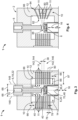
- shows a schematic perspective sectional view of a switching device according to a possible embodiment;
- Fig. 2
- shows a schematic sectional view of the switching device shown in
Fig. 1 ; - Fig. 3
- shows a schematic sectional view of the switching device shown in
Fig. 1 and Fig. 2 ; - Fig. 4
- shows a schematic sectional view of a switching device according to another possible embodiment;
- Fig. 5
- shows a schematic sectional view of a switching device according to even another possible embodiment;
- Fig. 6
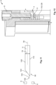
- shows a schematic sectional view of an arc splitting blade according to a possible embodiment;
- Fig. 7
- shows a schematic top view of an arc splitting blade according to a possible embodiment;
- Fig. 8
- shows a schematic sectional view of a switching device according to a possible embodiment, the switching device being in an operating state and the contacts being in a closed position;
- Fig. 9
- shows a schematic sectional view of a switching device according to a possible embodiment, the switching device being in an operating state and the contacts being in an open position;
- Fig. 10
- shows a schematic sectional view of a switching device according to another possible embodiment of the invention;
- Fig. 11
- shows a schematic sectional view of an arc splitting blade according to a further possible embodiment;
- Fig. 12
- shows a schematic perspective sectional view of a switching device according to another possible embodiment;
- Fig. 13
- shows a schematic sectional view of the contact chamber of the switching device according to
Fig. 9 . - In the following, the structure of switching devices according to several possible embodiments is described with reference to
Fig.1 to Fig. 13 . It should be noted that - according to some embodiments - twopairs 4 ofcontacts 6, twoblowout magnets 8 and at least twostacks 10 ofarc splitting blades 11 are shown. The invention is not limited to these embodiments, as they are purely exemplary and serve for illustration purposes only. As can be seen inFig. 12 , theswitching device 1 may also have only asingle pair 4 ofcontacts 6, only oneblowout magnet 8, and asingle stack 10 ofarc splitting blades 11. - The following descriptions refer to
Fig. 1 to Fig. 13 . - The
contact device 1 comprises ahousing 2, twopairs 4 ofcontacts 6,blowout magnets 8, and stacks 10 ofarc splitting blades 11. Thehousing 2 has a substantially cuboid shape and comprises ahousing wall 12 that encloses acontact chamber 14. Inside thecontact chamber 14, thepairs 4 ofcontacts 6 are arranged. Eachpair 4 ofcontacts 6 comprises twocontacts 6 that are adapted to be opened and closed along a switchingdirection 16. In the embodiment ofFig. 1 , each pair for ofcontacts 6 comprises a stationary contact 18 and a movable contact 20. The stationary contacts 18 are substantially cylindrical contact studs 22 that are partially received in thehousing wall 12. The movable contacts 20 of bothpairs 4 ofcontacts 6 are located on acontact bridge 24, which is connected to aplunger 26 by a contact bridge holder 30 and aspring 32. Thecontact bridge 24 is, together with the movable contacts 20, movable along the switchingdirection 16. - When the
pair 4 ofcontacts 6 are in an open position 34, i. e. when thecontacts 6 of thesame pair 4 ofcontacts 6 are spaced apart from one another along the switchingdirection 16, acontact gap 36 is formed between thecontacts 6. Thecontact gap 36 has alength 38 with respect to the switchingdirection 16. In the shown embodiment, thelength 38 of thecontact gap 36 is the distance between thecontacts 6, in particular betweencontact pills 40 of thesame pair 4 ofcontacts 6. Thecontact pills 40 may be located at an axial end 42 of each of thecontacts 6 facing towards thecontact gap 36. Thecontact pills 40 are configured to contact each other when thecontacts 6 of apair 4 ofcontacts 6 are in a closed position 44 (seeFig. 8 ). - As best seen in
Fig. 2 , acontact 6 may further comprise a contact head 46. In the shown embodiment, the contact head 46 is located at the axial ends 47 of the contact studs 22. The contact head 46 has a convex curvature with respect to alongitudinal axis 48 of each contact stud 20. The contact head 46 may further comprise ashoulder 50, arear surface 52 of theshoulder 50 facing away from thecontact gap 36. In particular, anormal axis 54 of therear surface 52 of theshoulder 50 may extend along thelongitudinal axis 48 of the contact studs 22 and away from thecontact gap 36. - As further seen in
Fig. 2 , thecontact device 1 may comprise twocuboid blowout magnets 8 that are positioned on an outer surface 56 of thehousing wall 12. Theblowout magnets 8 are oriented parallel to each other andnormal axes 58 of theblowout magnets 8 extend along aconnection line 60 between the stationary contacts 18. In an operatingstate 62, theblowout magnets 8 create a magnetic field for exerting amagnetic force 134 on anarc 64 occurring in thecontact chamber 14 when thecontacts 6 are in the open position 34. In the operatingstate 62, the magnetic field of theblowout magnets 8 at least partially penetrates thecontact chamber 14. In the embodiment shown inFig. 2 , thepair 4 ofcontacts 6 and thestacks 10 ofarc splitting blades 11 are positioned between theblowout magnets 8 and thus, in the operatingstate 62, are affected by the magnetic field created by theblowout magnets 8. - In the embodiments of
Fig. 1 and Fig. 2 , eachpair 4 ofcontacts 6 has twostacks 10 ofarc splitting blades 11, thestacks 10 being opposite to one another with respect to thecontact gap 36. Eachstack 10 ofarc splitting blades 11 comprises multiplearc splitting blades 11 that are spaced apart from each other along a stackingdirection 66. In the shown embodiments, the stackingdirection 66 extends along the switchingdirection 16 and perpendicular to thenormal axes 58 of theblowout magnets 8. Thearc splitting blades 11 of eachstack 10 are electrically decoupled from one another and are provided for receiving and splitting arcs 64 occurring inside thecontact chamber 14 and being deflected by theblowout magnets 8 towards thearc splitting blades 11. - As best seen in
Fig. 3 , at least onestack 10 ofarc splitting blades 11 may at least partially overlap - with respect to the switching direction 16 - sections 142 adjacent to thecontact gap 36 with respect to the switchingdirection 16. In particular, an upper section 144 may extend from thecontact pill 40 of the stationary contact 18 along the switchingdirection 16 and away from thecontact gap 36, and a lower section 146 may extend from thecontact pill 40 of the movable contact 20 along the switchingdirection 16 and away from thecontact gap 36. In the embodiment shown inFig. 3 , equal numbers ofarc splitting blades 11 overlap both the upper section 144 and the lower section 146 with respect to the switchingdirection 16. In particular, 3arc splitting blades 11 overlap both the upper section 144 and the lower section 146 with respect to the switchingdirection 16, while twoarc splitting blades 11 overlap thecontact gap 36 with respect to the switchingdirection 16. - The
distance 68 between the at least onestack 10 ofarc splitting blades 11 and thecontact gap 36 is smaller than 3lengths 38 of thecontact gap 36. Thedistance 68 between the at least onestack 10 ofarc splitting blades 11 and thecontact gap 36 may represent the shortest distance between acontact gap axis 70, which extends through thecontact pills 40 of bothcontacts 6 of thesame pair 4 ofcontacts 6, and anend plane 148 of thestack 10 facing towards thecontacts 6. Theend plane 148 of the stack extends through the arc splitting blade ends 82 facing towards thecontacts 6. In the embodiment shownFig. 3 , allarc splitting blades 11 of bothstacks 10 protrude from thehousing wall 12 into thecontact chamber 14 to the same extent, so that the end planes 148 of thestacks 10 ofarc splitting blades 11 are parallel to thecontact gap axis 70. Thecontact gap axis 70 of theswitching device 1 shown inFig. 3 is identical to thelongitudinal axis 48 of the contact stud 22. - In the embodiment shown in
Fig. 1 , each of thearc splitting blades 11 is separately received inside thehousing wall 12 of thehousing 2. Thearc splitting blades 11 may be overmolded by thehousing 2. - As shown in
Fig. 10 , theswitching device 1 may further comprise aninsert 74. Theinsert 74 comprises astack 10 ofarc splitting blades 11, of which each is attached to theinsert 74. In the embodiment shown, theinsert 74 is press-fitted into thehousing wall 12 of thehousing 2. - As best seen in
Fig. 3 , thearc splitting blades 11 may be arranged parallel to each other and adjacentarc splitting blades 11 may be spaced apart from each other by adistance 76. According to a possible embodiment, thedistance 76 between adjacentarc splitting blades 11 of astack 10 ofarc splitting blades 11 may be maximally about 75% of thelength 38 of thecontact gap 36. According to a further embodiment, thedistance 76 of adjacentarc splitting blades 11 may be at least as large as athickness 78 of thearc splitting blades 11. Thethickness 78 of thearc splitting blades 11 may be measured along the stackingdirection 66. In case thearc splitting blades 11 havedifferent thicknesses 78, thedistance 76 of adjacentarc splitting blades 11 may be at least as large as the thickest of thearc splitting blades 11. - According to a possible embodiment shown in
Fig. 4 , at least twoarc splitting blades 11 of astack 10 ofarc splitting blades 11 may have aninclination 80 relative to each other. InFig. 4 , all pairs 10 of adjacentarc splitting blades 11 have thesame inclination 80 relative to each other and allarc splitting blades 11 point towards thecontact gap 36. In particular, a distance between theends 82 of two adjacentarc splitting blades 11 facing towards thecontacts 6 is smaller than a distance between theends 84 facing away from thecontacts 6 of two adjacentarc splitting blades 11 with respect to the switchingdirection 16. - Each of the
arc splitting blades 11 protrudes from aninner side 86 of thehousing wall 12 towards thecontacts 6, so that ends 82 of thearc splitting blades 11 facing towards thecontacts 6 are located in thecontact chamber 14. In the embodiment ofFig. 3 , allarc splitting blades 11 protrude perpendicularly from thehousing wall 12. Further, allarc splitting blades 11 shown inFig. 3 have thesame length 87 and protrude equally far from theinner side 86 of thehousing wall 12 into thecontact chamber 14. In particular, a protrudingdistance 88 with respect tolongitudinal axes 90 of thearc splitting blades 11 between ends 82 of thearc splitting blades 11 facing towards thecontacts 6 and theinner side 86 of thehousing wall 12 may be identical for allarc splitting blades 11. - According to a further embodiment, the
arc splitting blades 11 may protrude from theinner side 86 of thehousing wall 12 into thecontact chamber 14 to different extents. As shown inFig. 5 , thearc splitting blades 11 closest to acenter plane 92 of thestack 10 ofarc splitting blades 11 may for example have the smallest protrudingdistance 88 and thearc splitting blades 11 that are spaced apart furthest from thecenter plane 92 of thestack 10 ofarc splitting blades 11 with respect to the stackingdirection 66 may have the largest protrudingdistance 88. Thecenter plane 92 extends perpendicular to the stackingdirection 66 and is arranged in the middle of a top splitter blade 94 and a bottom splitter blade 96 with respect to the stackingdirection 66. Of allarc splitting blades 11 in astack 10 ofarc splitting blades 11, the top splitter blade 94 and the bottom splitter blade 96 may be furthest away from thecenter plane 92 with respect to the stackingdirection 66. - As seen in
Fig. 6 , thearc splitting blades 11 further may comprise a taperedsection 98 that is located at theends 82 of thearc splitting blades 11 facing towards thecontacts 6. The taperedsection 98 shown inFig. 6 comprisesbevels 100 that taper along thelongitudinal axis 90 of thearc splitting blades 11 and towards thecontacts 6. Thethickness 78 of thearc splitting blades 11 decreases along thelongitudinal axis 90 of thearc splitting blade 11 and towards thecontacts 6. At anend 102 of the taperedsection 98 facing towards thecontacts 6, thearc splitting blades 11 comprises anedge 104 that extends along awhole width 106 of thearc splitting blades 11. As shown inFig. 1 , thewidth 106 of thearc splitting blades 11 may extend along theconnection line 60 between two stationary contacts 18. According to another embodiment, theedge 104 may only extend sectionally along thewidth 106 of thearc splitting blades 11. - The tapered
section 98 may also be designed differently. The taperedsection 98 of the embodiment shown inFig. 11 has only asingle bevel 100 extending from atop surface 108 to abottom surface 110 of thearc splitting blade 11 and thus tapers along thelongitudinal axis 90 of thearc splitting blades 11 and towards thecontacts 6. Thethickness 78 of thearc splitting blade 11 decreases along thelongitudinal axis 90 of thearc splitting blade 11 and towards thecontacts 6. At theend 102 of the taperedsection 98 facing towards thecontacts 6, thebevel 100 ends in anedge 104 that is located on thebottom surface 110. According to another embodiment, theedge 104 may be located on thetop surface 108 of thearc splitting blade 11. - According to a further embodiment, at least one
arc splitting blade 11 may comprise arecess 112 at anend 82 of thearc splitting blade 11 facing towards thecontacts 6. Therecess 112 shown inFig. 7 is formed by a substantiallyU-shaped end section 114 of thearc splitting blade 11. In particular, the U-shapedarc splitting blade 11 comprises twolegs 116 that are opposite to each other with respect to thelongitudinal axis 90 of thearc splitting blade 11. Thus, therecess 112 is built symmetrically to thelongitudinal axis 90 of thearc splitting blade 11. - In the following, the function of a
switching device 1 according to a possible embodiment is described with respect toFig. 8 ,Fig. 9 andFig. 13 . - In the operating
state 62, an electrical current flows through theswitching device 1, as thecontacts 6 are in theclosed position 44. Thecontacts 6 of eachpair 4 ofcontacts 6 are in contact with each other, so that thecontact pills 40 of thecontacts 6 of eachpair 4 ofcontacts 6 abut each other. As indicated by the dotted line inFig. 8 , a path of the electrical current 118 may extend from a first stationary contact 120 to a first movable contact 122, from the first movable contact 122 to a second movable contact 124 via thecontact bridge 24, and from the second movable contact 124 to a second stationary contact 126. Allcontacts 6 thus may form an electrical circuit 128. According to the embodiment of theswitching device 1 shown inFig. 12 , only twocontacts 6 of thesame pair 4 ofcontacts 6 may form an electrical circuit 128, so that the path of the electrical current 118 may extend between twocontacts 6 of thesame pair 4 of contacts 6 (indicated through dotted line). - As the
contact bridge 24 comprising the movable contacts 20 is moved away from the stationary contacts 18, thecontacts 6 of eachpair 4 ofcontacts 6 are moved from theclosed position 44 into the open position 34. As a result, thecontact gap 36 is formed between both the first stationary contact 120 and the first movable contact 122 as well as between the second stationary contact 126 and the second movable contact 124. As the current flow is abruptly interrupted during opening of thecontacts 6, arcs 64 may occur in thecontact gap 36. In the embodiment ofFig. 9 , anarc 64 is formed in eachcontact gap 36. As long as thearc 64 is not deflected by the at least oneblowout magnet 8, eacharc 64 has an initial direction of movement 130 which, in the embodiment shown, extends along the connectingline 132 of thecontact pills 40 of eachpair 4 of contacts 6 (see detail view inFig. 13 ) - In the operating
state 62, theblowout magnets 8 create a magnetic field, which penetrates thecontact chamber 14. As thearcs 64 occur and move along the initial direction of movement 130, the magnetic field created by theblowout magnets 8 distracts thearcs 64 by exerting amagnetic force 134 on thearcs 64. Themagnetic force 134 thereby points in a direction perpendicular to a direction of movement 136 of thearcs 64 and perpendicular to thefield lines 138 of the magnetic field. Consequently, eacharc 64 is distracted towards anarc splitting blade 11 that absorbs thearc 64. As thearc splitting blades 11 of eachstack 10 ofarc splitting blades 11 are electrically decoupled from one another, the adsorbedarc 64 jumps over to an adjacentarc splitting blade 11. In this way, eacharc 64 is split into multiplesmaller arcs 64, until thearcs 64 are completely extinguished. - The current flow through the
switching device 1 may be bidirectional. In case theswitching device 1 is used e.g. for switching an alternating current, the polarization of the current changes periodically. As a result, the direction of the current flow between thecontacts 6 of a pair ofcontacts 4 also changes periodically. The directions of the current flow may be opposite to each other. Arcs occurring during opening of thecontacts 6 thus may have different initial directions of movement 130, which may be exactly opposite to each other in dependence on the alternating directions of the current flow. Since - according to the right-hand rule - themagnetic force 134 exerted on thearcs 64 extends perpendicular to the direction of movement 136 of thearcs 64 and perpendicular to thefield lines 138 of the magnetic field created by the at least oneblowout magnet 8, thearcs 64 are deflected in opposite directions depending on the direction of the current. In order to allarcs 64 be absorbed regardless of their direction of deflection, two opposingstacks 10 ofarc splitting blades 11 may be provided. -
- 1
- switching device
- 2
- housing
- 4
- pair of contacts
- 6
- contact
- 8
- blowout magnet
- 10
- stack of arc splitting blades
- 11
- arc splitting blade
- 12
- housing wall
- 14
- contact chamber
- 16
- switching direction
- 18
- stationary contact
- 20
- movable contact
- 22
- contact studs
- 24
- contact bridge
- 26
- plunger
- 30
- contact bridge holder
- 32
- spring
- 34
- open position
- 36
- contact gap
- 38
- length of the contact gap
- 40
- contact pill
- 42
- axial end of the contacts facing towards the contact gap
- 44
- closed position
- 46
- contact head
- 47
- axial end of the contact stud facing towards the contact gap
- 48
- longitudinal axis of the contact stud
- 50
- shoulder
- 52
- rear surface of the shoulder
- 54
- normal axis of the rear surface
- 56
- outer surface of the housing wall
- 58
- normal axis of the blowout magnet
- 60
- connection line between stationary contacts
- 62
- operating state
- 64
- arc
- 66
- stacking direction
- 68
- distance between stack and contact gap
- 70
- contact gap axis
- 74
- insert
- 76
- distance between adjacent arc splitting blades
- 78
- thickness of the arc splitting blades
- 80
- inclination
- 82
- end of arc splitting blade facing towards the contacts
- 84
- end of arc splitting blade facing away from the contacts
- 86
- inner side of the housing wall
- 87
- length of arc splitting blade
- 88
- protruding distance
- 90
- longitudinal axis of the arc splitting blade
- 92
- center plane of the stack
- 94
- top splitter blade
- 96
- bottom splitter blade
- 98
- tapered section
- 100
- bevel
- 102
- end of the tapered section facing towards the contacts
- 104
- edge
- 106
- width of the arc splitting blades
- 108
- top surface
- 110
- bottom surface
- 112
- recess
- 114
- end section of the arc splitting blade
- 116
- leg
- 118
- path of the electrical current
- 120
- first stationary contact
- 122
- first movable contact
- 124
- second movable contact
- 126
- second stationary contact
- 128
- electrical circuit
- 130
- initial direction of movement
- 132
- connecting line of the contact pills of a pair of contacts
- 134
- magnetic force
- 136
- direction of movement
- 138
- field line of the magnetic field
- 142
- section
- 144
- upper section
- 146
- lower section
- 148
- end plane
Claims (15)
- A switching device (1), comprisinga housing (2) having a contact chamber (14),at least one pair (4) of contacts (6), wherein the contacts (6) of the at least one pair (4) are arranged in the contact chamber (14) and are adapted to be moved from a closed position (44), in which the contacts (6) contact each other, to an open position (34), in which the contacts (6) are spaced apart from one another by a contact gap (36),at least one blowout magnet (8) configured to create a magnetic field for distracting arcs (64) generated in the open position (34),at least one stack (10) of electrically decoupled arc splitting blades (11) for receiving the arcs (64), the arc splitting blades (11) at least partially located in the contact chamber (14),wherein a distance (68) between the at least one stack (10) of arc splitting blades (11) and the contact gap (36) is smaller than 3 lengths of the contact gap (36).
- A switching device (1) according to claim 1,
wherein the arc splitting blades (11) of the at least one stack (10) of arc splitting blades (11) are arranged parallel to each other. - A switching device (1) according to claim 1,
wherein at least two arc splitting blades (11) being arranged in the same stack (10) of arc splitting blades (11) have an inclination (80) relative to each other. - A switching device (1) according to any one of claims 1 to 3,
wherein at least one arc splitting blade (11) of a stack (10) of arc splitting blades (11) protrudes further into the contact chamber (14) towards the contacts (6) than at least one other arc splitting blade (11) of the same stack (10) of arc splitting blades (11). - A switching device (1) according to any one of claims 1 to 4,
wherein at least one arc splitting blade (11) of the at least one stack (10) of arc splitting blades (11) comprises a recess (112) at an end (82) facing towards the contacts (6). - A switching device (1) according to any one of claims 1 to 5,
wherein the distance (76) between adjacent arc splitting blades (11) is less than 75% of the length (38) of the contact gap (36). - A switching device (1) according to any one of claims 1 to 6,
wherein the distance (76) of adjacent arc splitting blades (11) is at least as large as a thickness (78) of the arc splitting blades (11). - A switching device (1) according to any one of claims 1 to 7,
wherein at least one of the arc splitting blades (11) has at least one tapered section (98) at the end (82) facing towards the contacts (6). - A switching device (1) according to any one of claims 1 to 8,
wherein at least two stacks (10) of arc splitting blades (11) are arranged opposite to each other with respect to the contact gap (36). - A switching device (1) according to any one of claims 1 to 9,
wherein the housing (2) is at least partially made of ceramic. - A switching device (1) according to any one of claims 1 to 10,
wherein the at least one arc splitting blade (11) is overmolded by the housing (2). - A switching device (1) according to any one of claims 1 to 11,
wherein the switching device (1) comprises an insert (74) configured to be inserted into the housing (2), the insert (74) further comprising the at least one stack (10) of arc splitting blades (11). - A switching device (1) according to any one of claims 1 to 12,
wherein the at least one stack (10) of arc splitting blades (11) extends further along a switching direction (16) than the contact gap (36). - A switching device (1) according to claim 13,
wherein areas of the stack (10) that extend beyond the contact gap (36) each have an equal number of arc splitting blades (11). - A switching device (1) according to any one of claims 1 to 14,
wherein at least one of the arc splitting blades (11) is made of copper.
Priority Applications (1)
| Application Number | Priority Date | Filing Date | Title |
|---|---|---|---|
| EP23181766.9A EP4485490A1 (en) | 2023-06-27 | 2023-06-27 | Switching device with improved arc extinction |
Applications Claiming Priority (1)
| Application Number | Priority Date | Filing Date | Title |
|---|---|---|---|
| EP23181766.9A EP4485490A1 (en) | 2023-06-27 | 2023-06-27 | Switching device with improved arc extinction |
Publications (1)
| Publication Number | Publication Date |
|---|---|
| EP4485490A1 true EP4485490A1 (en) | 2025-01-01 |
Family
ID=87002984
Family Applications (1)
| Application Number | Title | Priority Date | Filing Date |
|---|---|---|---|
| EP23181766.9A Pending EP4485490A1 (en) | 2023-06-27 | 2023-06-27 | Switching device with improved arc extinction |
Country Status (1)
| Country | Link |
|---|---|
| EP (1) | EP4485490A1 (en) |
Citations (6)
| Publication number | Priority date | Publication date | Assignee | Title |
|---|---|---|---|---|
| JPS62198013A (en) * | 1986-02-25 | 1987-09-01 | 三菱電機株式会社 | Switchgear |
| DE102015013413A1 (en) * | 2015-10-19 | 2017-04-20 | Abb Ag | Electrical installation device with arc quenching device |
| DE102016213073A1 (en) * | 2016-07-18 | 2018-01-18 | Ellenberger & Poensgen Gmbh | switching system |
| US11056305B2 (en) * | 2016-05-31 | 2021-07-06 | Byd Company Limited | Relay |
| WO2022057606A1 (en) * | 2020-09-17 | 2022-03-24 | 华为数字能源技术有限公司 | Direct current contactor, distribution box, power battery assembly, and vehicle |
| US20230085584A1 (en) * | 2021-09-13 | 2023-03-16 | Song Chuan Precision Co., Ltd. | Electromagnetic relay |
-
2023
- 2023-06-27 EP EP23181766.9A patent/EP4485490A1/en active Pending
Patent Citations (6)
| Publication number | Priority date | Publication date | Assignee | Title |
|---|---|---|---|---|
| JPS62198013A (en) * | 1986-02-25 | 1987-09-01 | 三菱電機株式会社 | Switchgear |
| DE102015013413A1 (en) * | 2015-10-19 | 2017-04-20 | Abb Ag | Electrical installation device with arc quenching device |
| US11056305B2 (en) * | 2016-05-31 | 2021-07-06 | Byd Company Limited | Relay |
| DE102016213073A1 (en) * | 2016-07-18 | 2018-01-18 | Ellenberger & Poensgen Gmbh | switching system |
| WO2022057606A1 (en) * | 2020-09-17 | 2022-03-24 | 华为数字能源技术有限公司 | Direct current contactor, distribution box, power battery assembly, and vehicle |
| US20230085584A1 (en) * | 2021-09-13 | 2023-03-16 | Song Chuan Precision Co., Ltd. | Electromagnetic relay |
Similar Documents
| Publication | Publication Date | Title |
|---|---|---|
| EP2901468B1 (en) | Short-circuit shutdown switch | |
| CN114220718B (en) | DC circuit breaker | |
| KR100386845B1 (en) | Electrode structure for vacuum interrupter using aial magnetic field | |
| JP7179206B2 (en) | switch | |
| EP2393094A1 (en) | Switch unit with arc-extinguishing units | |
| KR102397524B1 (en) | Connection devices for electrical switches and electrical switches | |
| KR101401201B1 (en) | Vacuum valve | |
| US20240363296A1 (en) | Bi-directional double-break contactor | |
| WO2013140619A1 (en) | Current switch | |
| EP3193348B1 (en) | Arc chamber assembly and method | |
| KR20030023514A (en) | Contact arrangement for vacuum interrupter and vacuum interrupter using the contact arrangement | |
| EP0055008B1 (en) | Vacuum interrupter | |
| EP3051565B1 (en) | Contact module for breaker | |
| KR102820127B1 (en) | Electric switch limiter pole and dc electric switch comprising such a limiter pole | |
| US11804348B2 (en) | Arc path formation unit and direct current relay including same | |
| US10224162B2 (en) | Switching device with arc extinguishing device | |
| CN107004520A (en) | Switching device | |
| JP2022017498A (en) | Switch device including contact piece cover | |
| JPWO2019180931A1 (en) | Electromagnetic contactor | |
| EP2851921B1 (en) | Electrode assembly and vacuum interrupter including the same | |
| JP6838484B2 (en) | switch | |
| JP7110031B2 (en) | vacuum circuit breaker | |
| KR101601619B1 (en) | Vacuum valve | |
| JP7490152B2 (en) | Switchgear | |
| JP2003092050A (en) | Contact for vacuum interrupter and vacuum interrupter |
Legal Events
| Date | Code | Title | Description |
|---|---|---|---|
| PUAI | Public reference made under article 153(3) epc to a published international application that has entered the european phase |
Free format text: ORIGINAL CODE: 0009012 |
|
| STAA | Information on the status of an ep patent application or granted ep patent |
Free format text: STATUS: THE APPLICATION HAS BEEN PUBLISHED |
|
| AK | Designated contracting states |
Kind code of ref document: A1 Designated state(s): AL AT BE BG CH CY CZ DE DK EE ES FI FR GB GR HR HU IE IS IT LI LT LU LV MC ME MK MT NL NO PL PT RO RS SE SI SK SM TR |
|
| STAA | Information on the status of an ep patent application or granted ep patent |
Free format text: STATUS: REQUEST FOR EXAMINATION WAS MADE |
|
| 17P | Request for examination filed |
Effective date: 20250701 |