EP4485298A1 - Condition optimization device, condition optimization method, and program - Google Patents
Condition optimization device, condition optimization method, and program Download PDFInfo
- Publication number
- EP4485298A1 EP4485298A1 EP23759960.0A EP23759960A EP4485298A1 EP 4485298 A1 EP4485298 A1 EP 4485298A1 EP 23759960 A EP23759960 A EP 23759960A EP 4485298 A1 EP4485298 A1 EP 4485298A1
- Authority
- EP
- European Patent Office
- Prior art keywords
- value
- condition
- condition value
- physical property
- actual reaction
- Prior art date
- Legal status (The legal status is an assumption and is not a legal conclusion. Google has not performed a legal analysis and makes no representation as to the accuracy of the status listed.)
- Pending
Links
Images


Classifications
-
- G—PHYSICS
- G06—COMPUTING OR CALCULATING; COUNTING
- G06N—COMPUTING ARRANGEMENTS BASED ON SPECIFIC COMPUTATIONAL MODELS
- G06N7/00—Computing arrangements based on specific mathematical models
- G06N7/01—Probabilistic graphical models, e.g. probabilistic networks
-
- G—PHYSICS
- G05—CONTROLLING; REGULATING
- G05B—CONTROL OR REGULATING SYSTEMS IN GENERAL; FUNCTIONAL ELEMENTS OF SUCH SYSTEMS; MONITORING OR TESTING ARRANGEMENTS FOR SUCH SYSTEMS OR ELEMENTS
- G05B13/00—Adaptive control systems, i.e. systems automatically adjusting themselves to have a performance which is optimum according to some preassigned criterion
- G05B13/02—Adaptive control systems, i.e. systems automatically adjusting themselves to have a performance which is optimum according to some preassigned criterion electric
- G05B13/0265—Adaptive control systems, i.e. systems automatically adjusting themselves to have a performance which is optimum according to some preassigned criterion electric the criterion being a learning criterion
- G05B13/028—Adaptive control systems, i.e. systems automatically adjusting themselves to have a performance which is optimum according to some preassigned criterion electric the criterion being a learning criterion using expert systems only
-
- G—PHYSICS
- G06—COMPUTING OR CALCULATING; COUNTING
- G06N—COMPUTING ARRANGEMENTS BASED ON SPECIFIC COMPUTATIONAL MODELS
- G06N20/00—Machine learning
- G06N20/10—Machine learning using kernel methods, e.g. support vector machines [SVM]
-
- G—PHYSICS
- G06—COMPUTING OR CALCULATING; COUNTING
- G06N—COMPUTING ARRANGEMENTS BASED ON SPECIFIC COMPUTATIONAL MODELS
- G06N99/00—Subject matter not provided for in other groups of this subclass
-
- G—PHYSICS
- G16—INFORMATION AND COMMUNICATION TECHNOLOGY [ICT] SPECIALLY ADAPTED FOR SPECIFIC APPLICATION FIELDS
- G16B—BIOINFORMATICS, i.e. INFORMATION AND COMMUNICATION TECHNOLOGY [ICT] SPECIALLY ADAPTED FOR GENETIC OR PROTEIN-RELATED DATA PROCESSING IN COMPUTATIONAL MOLECULAR BIOLOGY
- G16B40/00—ICT specially adapted for biostatistics; ICT specially adapted for bioinformatics-related machine learning or data mining, e.g. knowledge discovery or pattern finding
-
- G—PHYSICS
- G16—INFORMATION AND COMMUNICATION TECHNOLOGY [ICT] SPECIALLY ADAPTED FOR SPECIFIC APPLICATION FIELDS
- G16C—COMPUTATIONAL CHEMISTRY; CHEMOINFORMATICS; COMPUTATIONAL MATERIALS SCIENCE
- G16C20/00—Chemoinformatics, i.e. ICT specially adapted for the handling of physicochemical or structural data of chemical particles, elements, compounds or mixtures
- G16C20/70—Machine learning, data mining or chemometrics
Definitions
- the present invention relates to condition optimization devices, condition optimization methods, and programs.
- Bayesian optimization is used for optimizing condition values. According to Bayesian optimization, condition values to be experimented next can be obtained based on a plurality of actual reaction values obtained in accordance with different condition values.
- the response surface method by a support vector machine is used. According to the response surface method, the best actual reaction values at certain condition values can be predicted.
- Patent Document 1 discloses a technique of evaluating a combination of a plurality of parameters by Bayesian optimization, thereby efficiently designing a device.
- Patent Document 1 Japanese Unexamined Patent Application Publication No. 2019-215750
- a condition optimization device includes: an actual reaction value obtainment unit configured to obtain an actual reaction value by observing a predetermined physical property value at a predetermined condition value; a condition value calculation unit configured to calculate a new condition value by Bayesian optimization; an optimum condition value prediction unit configured to predict, by a response surface method, a best physical property value and an optimum condition value at which the best physical property value is obtainable; a first determination unit configured to determine whether or not convergence has occurred based on the condition value corresponding to the actual reaction value and based on the new condition value; and a second determination unit configured to determine, upon the first determination unit determining that the convergence has occurred, whether or not convergence has occurred based on a difference between the physical property value observed at the optimum condition value and the best physical property value.
- the first embodiment of the present invention is a condition optimization system configured to optimize a condition value based on accumulated actual reaction values.
- the condition optimization system according to the present embodiment calculates a condition value to be experimented next by Bayesian optimization, and determines whether or not the condition value has converged utilizing the response surface method by a support vector machine (hereinafter referred to simply as "response surface method").
- response surface method a support vector machine
- FIG. 1 is a block diagram illustrating an example of the overall configuration of the condition optimization system according to the present embodiment.
- a condition optimization system 1 includes a condition optimization device 10 and a user terminal 20.
- the condition optimization system 1 according to the present embodiment may include a nucleic acid synthesizing device 31, an autosampler 32, and a spectrophotometer 33.
- the condition optimization device 10, the user terminal 20, the nucleic acid synthesizing device 31, the autosampler 32, and the spectrophotometer 33 are connected to enable data communication via a communication network N1, such as a Local Area Network (LAN), the Internet, or the like.
- LAN Local Area Network
- the condition optimization device 10 is an information processing device, such as a Personal Computer (PC), a workstation, a server, or the like, configured to optimize the condition value based on the accumulated actual reaction values.
- the condition optimization device 10 accumulates the actual reaction values input from the user terminal 20, and outputs a condition value to be experimented next to the user terminal 20 based on the accumulated actual reaction values.
- the condition optimization device 10 determines whether or not the condition value has converged every time the condition value is calculated, and outputs an optimized condition value to the user terminal 20 upon determining that the condition value has converged.
- the user terminal 20 is an information processing device used by a user, such as a Personal Computer (PC), a workstation, a server, or the like.
- the user terminal 20 shows the user the condition value output by the condition optimization device 10, and inputs an actual reaction value observed in accordance with the condition value to the condition optimization device 10.
- PC Personal Computer
- the user terminal 20 shows the user the condition value output by the condition optimization device 10, and inputs an actual reaction value observed in accordance with the condition value to the condition optimization device 10.
- the nucleic acid synthesizing device 31, the autosampler 32, and the spectrophotometer 33 are a configuration that automatically obtains the actual reaction value when optimizing the condition values of nucleic acid synthesis.
- the nucleic acid synthesizing device 31 is, for example, a device configured to synthesize DNA oligonucleotides.
- the autosampler 32 is a device configured to obtain a synthesized sample from the nucleic acid synthesizing device 31.
- the spectrophotometer 33 is a device configured to measure absorbance from the sample obtained by the autosampler 32. Data indicating absorbance measured by the spectrophotometer 33 is input to the condition optimization device 10 as an actual reaction value.
- condition optimization system 1 illustrated in FIG. 1 is merely illustrative, and various system configuration examples are possible in accordance with applications and purposes.
- the condition optimization device 10 may be realized by a plurality of computers or may be realized as a cloud computing service.
- condition optimization system 1 may be realized by a stand-alone information processing device having the functions of both the condition optimization device 10 and the user terminal 20.
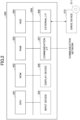
- FIG. 2 is a block diagram illustrating an example of the hardware configuration of a computer 500 according to the present embodiment.
- the computer 500 includes a Central Processing Unit (CPU) 501, a Read Only Memory (ROM) 502, a Random Access Memory (RAM) 503, a Hard Disk Drive (HDD) 504, an input device 505, a display device 506, a communication interface (I/F) 507, and an external I/F 508.
- the CPU 501, the ROM 502, and the RAM 503 form what is generally referred to as a computer.
- the respective hardware pieces of the computer 500 are mutually connected through a bus line 509.
- the input device 505 and the display device 506 may be used while being connected to the external I/F 508.
- the CPU 501 is an operating device configured to realize controls and functions of the entirety of the computer 500 by reading out programs and data onto the RAM 503 from a memory device, such as the ROM 502, the HDD 504, or the like, and executing processes.
- the ROM 502 is an example of a nonvolatile semiconductor memory (memory device) that can retain programs and data even when power supply is cut.
- the ROM 502 functions as a main memory device configured to store, for example, various programs and data necessary for the CPU 501 to execute various programs installed on the HDD 504.
- the ROM 502 stores boot programs, such as Basic Input/Output System (BIOS), Extensible Firmware Interface (EFI), and the like, that are executed when the computer 500 is started, and data, such as Operating System (OS) settings, network settings, and the like.
- BIOS Basic Input/Output System
- EFI Extensible Firmware Interface
- the RAM 503 is an example of a volatile semiconductor memory (memory device) from which programs and data are erased when power supply is cut.
- the RAM 503 is, for example, a Dynamic Random Access Memory (DRAM), a Static Random Access Memory (SRAM), or the like.
- the RAM 503 provides a work area in which various programs installed on the HDD 504 are deployed when executed by the CPU 501.
- the HDD 504 is an example of a nonvolatile memory device storing programs and data.
- the programs and data stored in the HDD 504 include OS, which is basic software for controlling the entirety of the computer 500, and applications that provide various functions on the OS.
- the computer 500 may employ a memory device using a flash memory as a memory medium (e.g., a Solid State Drive (SSD) or the like), instead of the HDD 504.
- SSD Solid State Drive
- the input device 505 is, for example, a touch panel, operation keys or buttons, or a keyboard or a mouse by which a user enters various signals, or a microphone by which a user enters sound data, such as sound and voice.
- the display device 506 is formed by a liquid crystal or organic Electro-Luminescence (EL) display configured to display a screen, and a loudspeaker configured to output sound data, such as sound and voice.
- EL Electro-Luminescence
- the communication I/F 507 is an interface configured to connect to a communication network in order that the computer 500 can perform data communication.
- the external I/F 508 is an interface to an external device.
- An example of the external device is a drive device 510 or the like.
- the drive device 510 is a device configured for a recording medium 511 to be set therein.
- the recording medium 511 meant here encompasses media configured to record information optically, electrically, or magnetically, such as a CD-ROM, a flexible disk, and a magneto-optical disk.
- the recording medium 511 may also encompass, for example, semiconductor memories configured to record information electrically, such as a ROM, a flash memory, and the like.
- the computer 500 can perform either or both of reading from and writing into the recording medium 511 via the external I/F 508.
- Various programs to be installed on the HDD 504 are installed, for example, by a distributed recording medium 511 being set in the drive device 510 connected to the external I/F 508, and various programs recorded in the recording medium 511 being read out by the drive device 510.
- various programs to be installed on the HDD 504 may be installed by being downloaded from any other network different from the communication network via the communication I/F 507.
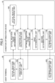
- FIG. 3 is a block diagram illustrating an example of the functional configuration of the condition optimization system according to the present embodiment.
- the condition optimization device 10 includes an actual reaction value storage unit 100, an actual reaction value obtainment unit 101, a condition value calculation unit 102, an optimum condition value prediction unit 103, a first determination unit 104, a second determination unit 105, and an optimum condition value output unit 106.
- the actual reaction value storage unit 100 is realized using, for example, the HDD 504 illustrated in FIG. 2 .
- the actual reaction value obtainment unit 101, the condition value calculation unit 102, the optimum condition value prediction unit 103, the first determination unit 104, the second determination unit 105, and the optimum condition value output unit 106 are realized through processes executed by the CPU 501 in accordance with the programs deployed on the RAM 503 from the HDD 504 illustrated in FIG. 2 .
- the actual reaction value storage unit 100 is configured to accumulate the actual reaction value received from the user terminal 20.
- the condition value used upon obtaining the actual reaction value is associated with this actual reaction value. That is, the actual reaction value storage unit 100 stores a plurality of condition values and actual reaction values that were used and obtained in the past. In the following, the newest condition value stored in the actual reaction value storage unit 100 is also referred to as "previous condition value".
- the actual reaction value obtainment unit 101 is configured to receive the actual reaction value from the user terminal 20. Also, the actual reaction value obtainment unit 101 is configured to associate the received actual reaction value with the condition value and store the associated actual reaction value in the actual reaction value storage unit 100.
- the condition value calculation unit 102 is configured to calculate a condition value to be experimented next based on the actual reaction value accumulated in the actual reaction value storage unit 100. Bayesian optimization is used for calculation of the condition value. In the following, the condition value calculated the most recently by the condition value calculation unit 102 is also referred to as "current condition value”.
- the optimum condition value prediction unit 103 is configured to predict, based on the actual reaction value accumulated in the actual reaction value storage unit 100, the best observable actual reaction value (hereinafter also referred to as “best physical property value”) and a condition value at which the best physical property value is obtainable (hereinafter also referred to as "optimum condition value").
- the response surface method is used for prediction of the best physical property value and the optimum condition value.
- the first determination unit 104 is configured to determine whether or not the condition value has converged based on the condition value calculated by the condition value calculation unit 102 and the condition value stored in the actual reaction value storage unit 100.
- the first determination unit 104 is configured to determine whether or not the condition value has converged based on the Euclidean distance between the current condition value and the previous condition value. That is, the first determination unit 104 calculates the Euclidean distance between each of the variables included in the condition value calculated by the optimum condition value prediction unit 103 and each of the variables included in the newest condition value stored in the actual reaction value storage unit 100. The first determination unit 104 compares the calculated Euclidean distance with a predetermined threshold, thereby determining whether or not the condition value has converged.
- the second determination unit 105 is configured to determine whether or not the condition value has converged based on the best physical property value and the actual reaction value observed in accordance with the optimum condition value predicted by the optimum condition value prediction unit 103 (hereinafter this actual reaction value is also referred to as "target physical property value").
- the second determination unit 105 is configured to determine whether or not the condition value has converged based on the difference between the target physical property value and the best physical property value. That is, the second determination unit 105 calculates the difference between the best physical property value predicted by the optimum condition value prediction unit 103 and the target physical property value obtained by the actual reaction value obtainment unit 101. The second determination unit 105 compares the calculated difference with a predetermined threshold, thereby determining whether or not the condition value has converged.
- the optimum condition value output unit 106 is configured to transmit, to the user terminal 20, the optimum condition value predicted the most recently by the optimum condition value prediction unit 103.
- the optimum condition value predicted the most recently by the optimum condition value prediction unit 103 is also referred to as "current optimum condition value”.
- the user terminal 20 includes an actual reaction value input unit 201, a condition value display unit 202, and an optimum condition value display unit 203.
- the actual reaction value input unit 201 is realized through a process executed by the CPU 501 and the input device 505 in accordance with the programs deployed on the RAM 503 from the HDD 504 illustrated in FIG. 2 .
- the condition value display unit 202 and the optimum condition value display unit 203 are realized through processes executed by the CPU 501 and the display device 506 in accordance with the programs deployed on the RAM 503 from the HDD 504 illustrated in FIG. 2 .
- the actual reaction value input unit 201 is configured to receive an input of an actual reaction value in response to a user's operation. Also, the actual reaction value input unit 201 is configured to transmit the received actual reaction value to the condition optimization device 10.
- the condition value display unit 202 is configured to receive the condition value from the condition optimization device 10. Also, the condition value display unit 202 is configured to display the received condition value on the display device 506.
- the optimum condition value display unit 203 is configured to receive the optimum condition value from the condition optimization device 10. Also, the optimum condition value display unit 203 is configured to display the received optimum condition value on the display device 506.
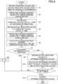
- FIG. 4 is a flowchart illustrating an example of the process of the condition optimization method according to the present embodiment.
- step S1 the actual reaction value input unit 201 receives an input of actual reaction values for N times by design of experiments in response to a user's operation. Next, the actual reaction value input unit 201 transmits the received actual reaction values for N times to the condition optimization device 10.
- the actual reaction value obtainment unit 101 receives the actual reaction values for N times from the user terminal 20. Next, the actual reaction value obtainment unit 101 stores the received actual reaction values for N times in the actual reaction value storage unit 100.
- the initial data is combinations of the condition values obtained in a wide range. Therefore, in the present embodiment, actual reaction values serving as the initial data are obtained by design of experiments.
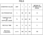
- FIG. 5 illustrates an example of the L9 orthogonal array.
- the 4 factors that are DCI percentage, temperature of supplied liquid, recycle time, and recycle flow rate are each changed to 3 levels illustrated as 1 to 3, i.e., the condition values for 9 times are used, thereby obtaining reaction rates observed at the condition values as actual reaction values.
- the condition values and the actual reaction values in the present embodiment are not limited thereto. Any experiment may be used as long as predetermined physical property values can be obtained at predetermined condition values.
- deprotection waste liquid after synthesis in the nucleic acid synthesizing device 31 is recovered by the autosampler 32 (available from Gilson Inc.).
- the recovered deprotection waste liquid is automatically diluted with a solution of 0.1M paratoluenesulfonic acid monohydrate (pTSA) in acetonitrile.
- pTSA paratoluenesulfonic acid monohydrate
- spectrophotometer 33 available from BAS Co., Ltd.
- the optimum condition value prediction unit 103 predicts, by the response surface method, the best physical property value and the optimum condition value based on the actual reaction values for N times stored in the actual reaction value storage unit 100.
- the best physical property value is the best observable actual reaction value (here, the maximum reaction rate).
- the optimum condition value prediction unit 103 transmits the predicted best physical property value to the second determination unit 105.
- step S3 the condition value calculation unit 102 calculates, by Bayesian optimization, condition values at the N+1 th time based on the actual reaction values for the N times accumulated in the actual reaction value storage unit 100.
- the condition value calculation unit 102 transmits the calculated condition values at the N+1 th time to the first determination unit 104.
- step S4 the condition value calculation unit 102 transmits the condition values at the N+1 th time calculated in step S3 to the user terminal 20.
- the condition value display unit 202 receives the condition values at the N+1 th time from the condition optimization device 10.
- the condition value display unit 202 displays the received condition values at the N+1 th time on the display device 506.
- the user performs the N+1 th experiment in accordance with the condition values at the N+1 th time displayed on the display device 506 of the user terminal 20.
- the user inputs the actual reaction values at the N+1 th time to the user terminal 20.
- the actual reaction value input unit 201 receives an input of the actual reaction values at the N+1 th time, and transmits the received actual reaction values to the condition optimization device 10. For example, like in step S1, if the deprotection waste liquid after nucleic acid synthesis is recovered and diluted by the autosampler 32 and the data of the actual reaction values can be automatically obtained by the spectrophotometer 33, the experiment can be performed continuously and efficiently.
- the actual reaction value obtainment unit 101 receives the actual reaction values at the N+1 th time from the user terminal 20. Next, the actual reaction value obtainment unit 101 associates the received actual reaction values at the N+1 th time with the condition values at the N+1 th time, and stores the associated actual reaction values in the actual reaction value storage unit 100.
- step S5 the optimum condition value prediction unit 103 predicts, by the response surface method, the best physical property value and the optimum condition value based on the actual reaction values for the N+1 times accumulated in the actual reaction value storage unit 100.
- the best physical property value is the best observable actual reaction value (here, the maximum reaction rate).
- the optimum condition value prediction unit 103 transmits the predicted best physical property value to the second determination unit 105.
- step S6 the first determination unit 104 receives the condition values at the N th time and the N+1 th time from the condition value calculation unit 102. Next, the first determination unit 104 calculates the Euclidean distance between the condition value at the N+1 th time and the condition value at the N th time.
- the first determination unit 104 calculates the Euclidean distance d(x,y), where x is the condition value at the N+1 th time, and y is the condition value at the N th time in accordance with the following formula.
- d x y x 1 ⁇ y 1 A 1 2 + ⁇ + x n ⁇ y n A n 2
- x 1 , ..., x n are each of the variables included in the condition values at the N+1 th time
- y 1 , ..., y n are each of the variables included in the condition values at the N th time
- step S7 the first determination unit 104 compares the Euclidean distance calculated in step S6 with a predetermined threshold, thereby determining whether or not the condition value has converged. Specifically, when the calculated Euclidean distance is 0.4 or shorter, it is determined that convergence has occurred.
- the first determination unit 104 determines that convergence has occurred (YES)
- the first determination unit 104 causes the process to proceed to step S9. Meanwhile, when the first determination unit 104 determines that convergence has not occurred (NO), the first determination unit 104 causes the process to proceed to step S8.
- step S8 the condition optimization device 10 increments N, i.e., calculates N ⁇ N+1. Subsequently, the process of from step S3 through step S7 is performed again.
- step S9 the optimum condition value prediction unit 103 transmits the optimum condition value calculated in step S2 to the user terminal 20.
- the condition value display unit 202 receives the optimum condition value from the condition optimization device 10.
- the condition value display unit 202 displays the received optimum condition value on the display device 506.
- the user performs an experiment in accordance with the optimum condition value displayed on the display device 506 of the user terminal 20.
- actual reaction values i.e., the target physical property value
- the user inputs the target physical property value to the user terminal 20.
- the actual reaction value input unit 201 receives an input of the target physical property value, and transmits the received target physical property value to the condition optimization device 10.
- the actual reaction value obtainment unit 101 receives the target physical property value from the user terminal 20. Next, the actual reaction value obtainment unit 101 transmits the received target physical property value to the second determination unit 105.
- step S10 the second determination unit 105 receives the best physical property value from the optimum condition value prediction unit 103.
- the second determination unit 105 receives the target physical property value from the actual reaction value obtainment unit 101.
- the second determination unit 105 calculates the difference between the best physical property value and the target physical property value.
- step S11 the second determination unit 105 compares the difference calculated in step S10 with a predetermined threshold, thereby determining whether or not the condition value has converged. Specifically, it is determined that convergence has occurred when the calculated difference is 1% or lower with respect to the best physical property value.
- the second determination unit 105 determines that convergence has occurred (YES)
- the second determination unit 105 causes the process to proceed to step S12. Meanwhile, when the second determination unit 105 determines that convergence has not occurred (NO), the second determination unit 105 causes the process to proceed to step S8.
- step S12 the optimum condition value output unit 106 transmits, to the user terminal 20, the optimum condition value predicted in the most-recently executed step S2 (i.e., the current optimum condition value).
- the optimum condition value display unit 203 receives the optimum condition value from the condition optimization device 10.
- the optimum condition value display unit 203 displays the received optimum condition value on the display device 506.
- the condition optimization system determines whether or not the condition value calculated by Bayesian optimization has converged by utilizing the response surface method.
- the response surface method can predict the best actual reaction value with a small number of experiments.
- the condition optimization system according to the present embodiment determines that the condition value has converged when the prediction accuracy by the response surface method is sufficiently high. Therefore, according to the condition optimization system of the present embodiment, it is possible to detect that the condition value has converged with a small number of experiments by utilizing the response surface method.
- an appropriate threshold for determining convergence is set by analyzing various actual reaction values. It is found that convergence can be determined with high accuracy when the Euclidean distance between the condition values is 0.4 or shorter and the difference between the predicted best physical property value and the actually measured physical property value is 1% or lower.
- condition optimization system it is possible to determine whether or not the condition value calculated by Bayesian optimization has converged with a small number of experiments. That is, according to the condition optimization system of the present embodiment, it is possible to efficiently optimize the conditions.
- the first determination unit 104 is configured to determine whether or not the condition value has converged based on the Euclidean distance between the current condition value and the previous condition value. In the second embodiment, the first determination unit 104 is configured to determine whether or not the condition value has converged based on the standard deviation of the current condition value and the most-recent condition values.
- condition optimization system 1 according to the present embodiment will be described by focusing on the differences from the condition optimization system 1 according to the first embodiment.
- FIG. 6 is a flowchart illustrating an example of the process of the condition optimization method according to the present embodiment.
- condition optimization method according to the present embodiment will be described by focusing on the differences from the first embodiment.
- step S6 the first determination unit 104 determines whether or not the condition value has converged based on the standard deviation of the condition values for the most-recent three times. That is, the first determination unit 104 calculates the standard deviation of: each of the variables included in the condition values calculated by the condition value calculation unit 102; and each of the variables included in the condition values for the most-recent two times stored in the actual reaction value storage unit 100.
- the first determination unit 104 calculates the standard deviation as follows: (1) obtaining a value by dividing the value of a variable included in the condition value at the N th time by the median of an optimization range of the variable, where the optimization range is a range between the upper limit and the lower limit of the values that can be taken by that variable as an experimental condition; (2) obtaining a value by dividing the value of the variable included in the condition value at the N-1 th time by the median of the optimization range of the variable; (3) obtaining a value by dividing the value of the variable included in the condition value at the N-2 th time by the median of the optimization range of the variable; (4) performing the above (1) to (3) for all variables; and (4) calculating the standard deviation of the values calculated in the above (1) to (3) for all variables included in the condition value.
- the example of calculating the standard deviation of the most-recent three times is described.
- the number of condition values for calculating the standard deviation is not limited.
- the standard deviation of the most-recent four or more times may be calculated.
- step S7 the first determination unit 104 compares each of the standard deviations of each variable calculated in step S6 with a predetermined threshold, thereby determining whether or not the condition value has converged. Specifically, when all of the calculated standard deviations are 0.2 or lower, it is determined that convergence has occurred.
- the condition optimization system determines whether or not the condition value calculated by Bayesian optimization has converged based on the standard deviation of each of the variables included in the condition value. At this time, an appropriate threshold for determining convergence is set by analyzing various actual reaction values. It is found that convergence can be determined with high accuracy when all of the standard deviations of each variable included in the condition value are 0.2 or lower.
- condition optimization system it is possible to determine whether or not the condition value calculated by Bayesian optimization has converged with a small number of experiments. That is, according to the condition optimization system according to the present embodiment, it is possible to efficiently optimize the conditions.
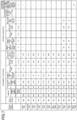
- FIG. 7 is a table illustrating actual reaction values according to the present embodiment.
- Porous resin beads were charged into a synthesis column (volume: 12.6 ml) so as to be of a synthesis scale of 480 pmol.
- the synthesis column was set in an oligonucleotide automatic synthesizing device.
- Nucleoside phosphoroamidite and 4,5-dicyanoimidazole (DCI) serving as an activating agent, were added thereto in the corresponding amounts described in FIG. 7 , followed by performing a coupling reaction under the conditions described in FIG. 7 .
- the activating agent was dissolved in acetonitrile and prepared to have a concentration of 0.7M.
- Other synthesis reagents used were: 3% DCA in toluene as a deprotecting agent; a 0.05M oxidizing solution for the above synthesis device, serving as an oxidant; a mixed solution of lutidine, N-methylimidazole, and acetic anhydride in acetonitrile, serving as a capping agent; and TBA in acetonitrile (at a ratio of 8:2), serving as an amine wash reaction solution. Under a DMT-off condition, 24 mer DNA oligonucleotides (5'-TCGACGTATTGACGTATTGACGTA-3', all oxidized: SEQ ID NO: 1) were synthesized.
- the reaction rate was measured as follows. DNA is synthesized 1 mer by 1 mer through the steps of deprotection, coupling, oxidation, and capping. Then, the reaction rate was evaluated by recovering all of the deprotection waste liquid of each mer and quantifying the deprotection group (DMTr) included therein. The deprotection rate was calculated through HPLC measurement after appropriate dilution with an acetonitrile solution of 0.1M para-toluenesulfonic acid monohydrate (pTSA).
- pTSA para-toluenesulfonic acid monohydrate
- the condition value to be experimented next was calculated by Bayesian optimization. Synthesis was performed at the calculated condition value, and the reaction rate was obtained in the same manner. The obtained result was added to the initial data, the condition value to be experimented next was calculated again by Bayesian optimization, synthesis was performed at the calculated condition value ...; this process was performed repeatedly. Prediction by the response surface method was performed at the same time as Bayesian optimization, and the maximum reaction rate predicted for each of the syntheses was obtained.
- the Euclidean distance between the condition value at the N th time and the condition value at the N-1 th time is 0.4 or lower.
- the difference between the reaction rate (actual reaction value) and the reaction rate (predicted value) is 1% or lower. Therefore, in the present embodiment, it is determined that the condition value has converged at the tenth time. Moreover, according to the actual reaction value, it can be found that the optimum condition value is obtained at the tenth time.
- condition optimization system can optimize the condition value with a small number of experiments.
- processing circuit encompasses devices such as a processor programmed by software to execute each function, such as a processor implemented on an electronic circuit, and an Application Specific Integrated Circuit (ASIC), a Digital Signal Processor (DSP), a Field Programmable Gate Array (FPGA), and existing circuit modules that are designed to execute each function described above.
- ASIC Application Specific Integrated Circuit
- DSP Digital Signal Processor
- FPGA Field Programmable Gate Array
Landscapes
- Engineering & Computer Science (AREA)
- Physics & Mathematics (AREA)
- Theoretical Computer Science (AREA)
- Software Systems (AREA)
- Artificial Intelligence (AREA)
- General Physics & Mathematics (AREA)
- Evolutionary Computation (AREA)
- Data Mining & Analysis (AREA)
- Medical Informatics (AREA)
- Computing Systems (AREA)
- General Engineering & Computer Science (AREA)
- Computer Vision & Pattern Recognition (AREA)
- Mathematical Physics (AREA)
- Health & Medical Sciences (AREA)
- Life Sciences & Earth Sciences (AREA)
- Pure & Applied Mathematics (AREA)
- Mathematical Optimization (AREA)
- Mathematical Analysis (AREA)
- Computational Mathematics (AREA)
- Algebra (AREA)
- Probability & Statistics with Applications (AREA)
- Bioinformatics & Computational Biology (AREA)
- General Health & Medical Sciences (AREA)
- Bioinformatics & Cheminformatics (AREA)
- Databases & Information Systems (AREA)
- Automation & Control Theory (AREA)
- Evolutionary Biology (AREA)
- Biophysics (AREA)
- Bioethics (AREA)
- Spectroscopy & Molecular Physics (AREA)
- Epidemiology (AREA)
- Biotechnology (AREA)
- Crystallography & Structural Chemistry (AREA)
- Chemical & Material Sciences (AREA)
- Public Health (AREA)
- Management, Administration, Business Operations System, And Electronic Commerce (AREA)
- Complex Calculations (AREA)
Abstract
Description
- The present invention relates to condition optimization devices, condition optimization methods, and programs.
- Bayesian optimization is used for optimizing condition values. According to Bayesian optimization, condition values to be experimented next can be obtained based on a plurality of actual reaction values obtained in accordance with different condition values.
- Meanwhile, in order to find optimum condition values with a small number of experiments, the response surface method by a support vector machine is used. According to the response surface method, the best actual reaction values at certain condition values can be predicted.
- For example,
Patent Document 1 discloses a technique of evaluating a combination of a plurality of parameters by Bayesian optimization, thereby efficiently designing a device. - Patent Document 1:
Japanese Unexamined Patent Application Publication No. 2019-215750 - However, in Bayesian optimization, it is necessary to perform many tests in order to determine whether or not the condition values have been optimized. Also, in the response surface method, the experimenter needs to set in advance the condition values to be experimented next.
- In view of the above technical issues, it is an object of one aspect of the present invention to efficiently optimize condition values.
- In order to address the above issues, a condition optimization device according to one aspect of the present invention includes: an actual reaction value obtainment unit configured to obtain an actual reaction value by observing a predetermined physical property value at a predetermined condition value; a condition value calculation unit configured to calculate a new condition value by Bayesian optimization; an optimum condition value prediction unit configured to predict, by a response surface method, a best physical property value and an optimum condition value at which the best physical property value is obtainable; a first determination unit configured to determine whether or not convergence has occurred based on the condition value corresponding to the actual reaction value and based on the new condition value; and a second determination unit configured to determine, upon the first determination unit determining that the convergence has occurred, whether or not convergence has occurred based on a difference between the physical property value observed at the optimum condition value and the best physical property value.
- According to one aspect of the present invention, it is possible to efficiently optimize condition values.
-
- [
FIG. 1] FIG. 1 is a diagram illustrating an example of an overall configuration of a condition optimization system according to an embodiment. - [
FIG. 2] FIG. 2 is a diagram illustrating an example of a hardware configuration of a computer according to an embodiment. - [
FIG. 3] FIG. 3 is a diagram illustrating an example of a functional configuration of the condition optimization system according to the embodiment. - [
FIG. 4] FIG. 4 is a diagram illustrating an example of a process of a condition optimization method according to a first embodiment. - [
FIG. 5] FIG. 5 is a diagram illustrating an example of condition values in accordance with design of experiments. - [
FIG. 6] FIG. 6 is a diagram illustrating an example of a process of a condition optimization method according to a second embodiment. - [
FIG. 7] FIG. 7 is a table illustrating an example of actual reaction values according to an embodiment. - Hereinafter, embodiments of the present invention will be described with reference to the attached drawings. In the present specification and drawings, components having substantially the same functional configuration are denoted by the same reference numerals, and thus duplicate description thereof will be omitted.
- The first embodiment of the present invention is a condition optimization system configured to optimize a condition value based on accumulated actual reaction values. The condition optimization system according to the present embodiment calculates a condition value to be experimented next by Bayesian optimization, and determines whether or not the condition value has converged utilizing the response surface method by a support vector machine (hereinafter referred to simply as "response surface method"). Thus, according to the condition optimization system according to the present embodiment, the condition value can be efficiently optimized with a small number of experiments.
- First, the overall configuration of the condition optimization system according to the present embodiment will be described with reference to
FIG. 1. FIG. 1 is a block diagram illustrating an example of the overall configuration of the condition optimization system according to the present embodiment. - As illustrated in
FIG. 1 , acondition optimization system 1 according to the present embodiment includes acondition optimization device 10 and auser terminal 20. Thecondition optimization system 1 according to the present embodiment may include a nucleicacid synthesizing device 31, anautosampler 32, and aspectrophotometer 33. Thecondition optimization device 10, theuser terminal 20, the nucleicacid synthesizing device 31, theautosampler 32, and thespectrophotometer 33 are connected to enable data communication via a communication network N1, such as a Local Area Network (LAN), the Internet, or the like. - The
condition optimization device 10 is an information processing device, such as a Personal Computer (PC), a workstation, a server, or the like, configured to optimize the condition value based on the accumulated actual reaction values. Thecondition optimization device 10 accumulates the actual reaction values input from theuser terminal 20, and outputs a condition value to be experimented next to theuser terminal 20 based on the accumulated actual reaction values. Thecondition optimization device 10 determines whether or not the condition value has converged every time the condition value is calculated, and outputs an optimized condition value to theuser terminal 20 upon determining that the condition value has converged. - The
user terminal 20 is an information processing device used by a user, such as a Personal Computer (PC), a workstation, a server, or the like. Theuser terminal 20 shows the user the condition value output by thecondition optimization device 10, and inputs an actual reaction value observed in accordance with the condition value to thecondition optimization device 10. - The nucleic
acid synthesizing device 31, theautosampler 32, and thespectrophotometer 33 are a configuration that automatically obtains the actual reaction value when optimizing the condition values of nucleic acid synthesis. The nucleicacid synthesizing device 31 is, for example, a device configured to synthesize DNA oligonucleotides. Theautosampler 32 is a device configured to obtain a synthesized sample from the nucleicacid synthesizing device 31. Thespectrophotometer 33 is a device configured to measure absorbance from the sample obtained by theautosampler 32. Data indicating absorbance measured by thespectrophotometer 33 is input to thecondition optimization device 10 as an actual reaction value. - The overall configuration of the
condition optimization system 1 illustrated inFIG. 1 is merely illustrative, and various system configuration examples are possible in accordance with applications and purposes. For example, thecondition optimization device 10 may be realized by a plurality of computers or may be realized as a cloud computing service. Further, for example, thecondition optimization system 1 may be realized by a stand-alone information processing device having the functions of both thecondition optimization device 10 and theuser terminal 20. - Next, the hardware configuration of the condition optimization system according to the present embodiment will be described with reference to
FIG. 2 . - The
condition optimization device 10 and theuser terminal 20 according to the present embodiment are realized, for example, by a computer.FIG. 2 is a block diagram illustrating an example of the hardware configuration of acomputer 500 according to the present embodiment. - As illustrated in
FIG. 2 , thecomputer 500 includes a Central Processing Unit (CPU) 501, a Read Only Memory (ROM) 502, a Random Access Memory (RAM) 503, a Hard Disk Drive (HDD) 504, aninput device 505, adisplay device 506, a communication interface (I/F) 507, and an external I/F 508. TheCPU 501, theROM 502, and theRAM 503 form what is generally referred to as a computer. The respective hardware pieces of thecomputer 500 are mutually connected through abus line 509. Theinput device 505 and thedisplay device 506 may be used while being connected to the external I/F 508. - The
CPU 501 is an operating device configured to realize controls and functions of the entirety of thecomputer 500 by reading out programs and data onto theRAM 503 from a memory device, such as theROM 502, theHDD 504, or the like, and executing processes. - The
ROM 502 is an example of a nonvolatile semiconductor memory (memory device) that can retain programs and data even when power supply is cut. TheROM 502 functions as a main memory device configured to store, for example, various programs and data necessary for theCPU 501 to execute various programs installed on theHDD 504. Specifically, theROM 502 stores boot programs, such as Basic Input/Output System (BIOS), Extensible Firmware Interface (EFI), and the like, that are executed when thecomputer 500 is started, and data, such as Operating System (OS) settings, network settings, and the like. - The
RAM 503 is an example of a volatile semiconductor memory (memory device) from which programs and data are erased when power supply is cut. TheRAM 503 is, for example, a Dynamic Random Access Memory (DRAM), a Static Random Access Memory (SRAM), or the like. TheRAM 503 provides a work area in which various programs installed on theHDD 504 are deployed when executed by theCPU 501. - The
HDD 504 is an example of a nonvolatile memory device storing programs and data. The programs and data stored in theHDD 504 include OS, which is basic software for controlling the entirety of thecomputer 500, and applications that provide various functions on the OS. Thecomputer 500 may employ a memory device using a flash memory as a memory medium (e.g., a Solid State Drive (SSD) or the like), instead of theHDD 504. - The
input device 505 is, for example, a touch panel, operation keys or buttons, or a keyboard or a mouse by which a user enters various signals, or a microphone by which a user enters sound data, such as sound and voice. - The
display device 506 is formed by a liquid crystal or organic Electro-Luminescence (EL) display configured to display a screen, and a loudspeaker configured to output sound data, such as sound and voice. - The communication I/
F 507 is an interface configured to connect to a communication network in order that thecomputer 500 can perform data communication. - The external I/
F 508 is an interface to an external device. An example of the external device is adrive device 510 or the like. - The
drive device 510 is a device configured for arecording medium 511 to be set therein. Therecording medium 511 meant here encompasses media configured to record information optically, electrically, or magnetically, such as a CD-ROM, a flexible disk, and a magneto-optical disk. Therecording medium 511 may also encompass, for example, semiconductor memories configured to record information electrically, such as a ROM, a flash memory, and the like. Hence, thecomputer 500 can perform either or both of reading from and writing into therecording medium 511 via the external I/F 508. - Various programs to be installed on the
HDD 504 are installed, for example, by a distributedrecording medium 511 being set in thedrive device 510 connected to the external I/F 508, and various programs recorded in therecording medium 511 being read out by thedrive device 510. Alternatively, various programs to be installed on theHDD 504 may be installed by being downloaded from any other network different from the communication network via the communication I/F 507. - Next, the functional configuration of the condition optimization system according to the present embodiment will be described with reference to
FIG. 3. FIG. 3 is a block diagram illustrating an example of the functional configuration of the condition optimization system according to the present embodiment. - As illustrated in
FIG. 3 , thecondition optimization device 10 according to the present embodiment includes an actual reactionvalue storage unit 100, an actual reactionvalue obtainment unit 101, a conditionvalue calculation unit 102, an optimum conditionvalue prediction unit 103, afirst determination unit 104, asecond determination unit 105, and an optimum conditionvalue output unit 106. - The actual reaction
value storage unit 100 is realized using, for example, theHDD 504 illustrated inFIG. 2 . The actual reactionvalue obtainment unit 101, the conditionvalue calculation unit 102, the optimum conditionvalue prediction unit 103, thefirst determination unit 104, thesecond determination unit 105, and the optimum conditionvalue output unit 106 are realized through processes executed by theCPU 501 in accordance with the programs deployed on theRAM 503 from theHDD 504 illustrated inFIG. 2 . - The actual reaction
value storage unit 100 is configured to accumulate the actual reaction value received from theuser terminal 20. The condition value used upon obtaining the actual reaction value is associated with this actual reaction value. That is, the actual reactionvalue storage unit 100 stores a plurality of condition values and actual reaction values that were used and obtained in the past. In the following, the newest condition value stored in the actual reactionvalue storage unit 100 is also referred to as "previous condition value". - The actual reaction
value obtainment unit 101 is configured to receive the actual reaction value from theuser terminal 20. Also, the actual reactionvalue obtainment unit 101 is configured to associate the received actual reaction value with the condition value and store the associated actual reaction value in the actual reactionvalue storage unit 100. - The condition
value calculation unit 102 is configured to calculate a condition value to be experimented next based on the actual reaction value accumulated in the actual reactionvalue storage unit 100. Bayesian optimization is used for calculation of the condition value. In the following, the condition value calculated the most recently by the conditionvalue calculation unit 102 is also referred to as "current condition value". - The optimum condition
value prediction unit 103 is configured to predict, based on the actual reaction value accumulated in the actual reactionvalue storage unit 100, the best observable actual reaction value (hereinafter also referred to as "best physical property value") and a condition value at which the best physical property value is obtainable (hereinafter also referred to as "optimum condition value"). The response surface method is used for prediction of the best physical property value and the optimum condition value. - The
first determination unit 104 is configured to determine whether or not the condition value has converged based on the condition value calculated by the conditionvalue calculation unit 102 and the condition value stored in the actual reactionvalue storage unit 100. - The
first determination unit 104 according to the present embodiment is configured to determine whether or not the condition value has converged based on the Euclidean distance between the current condition value and the previous condition value. That is, thefirst determination unit 104 calculates the Euclidean distance between each of the variables included in the condition value calculated by the optimum conditionvalue prediction unit 103 and each of the variables included in the newest condition value stored in the actual reactionvalue storage unit 100. Thefirst determination unit 104 compares the calculated Euclidean distance with a predetermined threshold, thereby determining whether or not the condition value has converged. - When the
first determination unit 104 determines that the condition value has converged, thesecond determination unit 105 is configured to determine whether or not the condition value has converged based on the best physical property value and the actual reaction value observed in accordance with the optimum condition value predicted by the optimum condition value prediction unit 103 (hereinafter this actual reaction value is also referred to as "target physical property value"). - The
second determination unit 105 according to the present embodiment is configured to determine whether or not the condition value has converged based on the difference between the target physical property value and the best physical property value. That is, thesecond determination unit 105 calculates the difference between the best physical property value predicted by the optimum conditionvalue prediction unit 103 and the target physical property value obtained by the actual reactionvalue obtainment unit 101. Thesecond determination unit 105 compares the calculated difference with a predetermined threshold, thereby determining whether or not the condition value has converged. - When the
second determination unit 105 determines that the condition value has converged, the optimum conditionvalue output unit 106 is configured to transmit, to theuser terminal 20, the optimum condition value predicted the most recently by the optimum conditionvalue prediction unit 103. In the following, the optimum condition value predicted the most recently by the optimum conditionvalue prediction unit 103 is also referred to as "current optimum condition value". - As illustrated in
FIG. 3 , theuser terminal 20 according to the present embodiment includes an actual reactionvalue input unit 201, a conditionvalue display unit 202, and an optimum conditionvalue display unit 203. - The actual reaction
value input unit 201 is realized through a process executed by theCPU 501 and theinput device 505 in accordance with the programs deployed on theRAM 503 from theHDD 504 illustrated inFIG. 2 . The conditionvalue display unit 202 and the optimum conditionvalue display unit 203 are realized through processes executed by theCPU 501 and thedisplay device 506 in accordance with the programs deployed on theRAM 503 from theHDD 504 illustrated inFIG. 2 . - The actual reaction
value input unit 201 is configured to receive an input of an actual reaction value in response to a user's operation. Also, the actual reactionvalue input unit 201 is configured to transmit the received actual reaction value to thecondition optimization device 10. - The condition
value display unit 202 is configured to receive the condition value from thecondition optimization device 10. Also, the conditionvalue display unit 202 is configured to display the received condition value on thedisplay device 506. - The optimum condition
value display unit 203 is configured to receive the optimum condition value from thecondition optimization device 10. Also, the optimum conditionvalue display unit 203 is configured to display the received optimum condition value on thedisplay device 506. - Next, the process of the condition optimization method executed by the condition optimization system according to the present embodiment will be described with reference to
FIG. 4. FIG. 4 is a flowchart illustrating an example of the process of the condition optimization method according to the present embodiment. - In step S1, the actual reaction
value input unit 201 receives an input of actual reaction values for N times by design of experiments in response to a user's operation. Next, the actual reactionvalue input unit 201 transmits the received actual reaction values for N times to thecondition optimization device 10. - In the
condition optimization device 10, the actual reactionvalue obtainment unit 101 receives the actual reaction values for N times from theuser terminal 20. Next, the actual reactionvalue obtainment unit 101 stores the received actual reaction values for N times in the actual reactionvalue storage unit 100. - According to Bayesian optimization, there should be initial data of the actual reaction values, and desirably, the initial data is combinations of the condition values obtained in a wide range. Therefore, in the present embodiment, actual reaction values serving as the initial data are obtained by design of experiments.
- In the present embodiment, assuming measurement of a reaction rate in the synthesis of DNA oligonucleotides, an L9 orthogonal array of 3 levels and 4 factors is used for input of actual reaction values for 9 times (i.e., N = 9).
FIG. 5 illustrates an example of the L9 orthogonal array. As illustrated inFIG. 5 , in the present embodiment, the 4 factors that are DCI percentage, temperature of supplied liquid, recycle time, and recycle flow rate are each changed to 3 levels illustrated as 1 to 3, i.e., the condition values for 9 times are used, thereby obtaining reaction rates observed at the condition values as actual reaction values. However, the condition values and the actual reaction values in the present embodiment are not limited thereto. Any experiment may be used as long as predetermined physical property values can be obtained at predetermined condition values. - For example, in the case of nucleic acid synthesis, first, deprotection waste liquid after synthesis in the nucleic
acid synthesizing device 31 is recovered by the autosampler 32 (available from Gilson Inc.). In theautosampler 32, the recovered deprotection waste liquid is automatically diluted with a solution of 0.1M paratoluenesulfonic acid monohydrate (pTSA) in acetonitrile. By using the spectrophotometer 33 (available from BAS Co., Ltd.), it is possible to automatically obtain data of actual reaction values (absorbance) from the deprotection group (DMTr) included in the deprotection waste liquid. With this configuration, experiments can be performed continuously and efficiently without the intervention of an experimenter. - As illustrated in
FIG. 4 , in step S2, the optimum conditionvalue prediction unit 103 predicts, by the response surface method, the best physical property value and the optimum condition value based on the actual reaction values for N times stored in the actual reactionvalue storage unit 100. The best physical property value is the best observable actual reaction value (here, the maximum reaction rate). The optimum condition value is the condition value at which obtainment of the maximum reaction rate at the Nth time (N = 9) is predicted. Next, the optimum conditionvalue prediction unit 103 transmits the predicted best physical property value to thesecond determination unit 105. - In step S3, the condition
value calculation unit 102 calculates, by Bayesian optimization, condition values at the N+1th time based on the actual reaction values for the N times accumulated in the actual reactionvalue storage unit 100. Next, the conditionvalue calculation unit 102 transmits the calculated condition values at the N+1th time to thefirst determination unit 104. - In step S4, the condition
value calculation unit 102 transmits the condition values at the N+1th time calculated in step S3 to theuser terminal 20. In theuser terminal 20, the conditionvalue display unit 202 receives the condition values at the N+1th time from thecondition optimization device 10. Next, the conditionvalue display unit 202 displays the received condition values at the N+1th time on thedisplay device 506. - The user performs the N+1th experiment in accordance with the condition values at the N+1th time displayed on the
display device 506 of theuser terminal 20. When the N+1th experiment is completed and actual reaction values are obtained, the user inputs the actual reaction values at the N+1th time to theuser terminal 20. The actual reactionvalue input unit 201 receives an input of the actual reaction values at the N+1th time, and transmits the received actual reaction values to thecondition optimization device 10. For example, like in step S1, if the deprotection waste liquid after nucleic acid synthesis is recovered and diluted by theautosampler 32 and the data of the actual reaction values can be automatically obtained by thespectrophotometer 33, the experiment can be performed continuously and efficiently. - In the
condition optimization device 10, the actual reactionvalue obtainment unit 101 receives the actual reaction values at the N+1th time from theuser terminal 20. Next, the actual reactionvalue obtainment unit 101 associates the received actual reaction values at the N+1th time with the condition values at the N+1th time, and stores the associated actual reaction values in the actual reactionvalue storage unit 100. - In step S5, the optimum condition
value prediction unit 103 predicts, by the response surface method, the best physical property value and the optimum condition value based on the actual reaction values for the N+1 times accumulated in the actual reactionvalue storage unit 100. The best physical property value is the best observable actual reaction value (here, the maximum reaction rate). The optimum condition value is the condition value at which obtainment of the maximum reaction rate at the N+1th time (N = 10) is predicted. Next, the optimum conditionvalue prediction unit 103 transmits the predicted best physical property value to thesecond determination unit 105. - In step S6, the
first determination unit 104 receives the condition values at the Nth time and the N+1th time from the conditionvalue calculation unit 102. Next, thefirst determination unit 104 calculates the Euclidean distance between the condition value at the N+1th time and the condition value at the Nth time. - Specifically, the
first determination unit 104 calculates the Euclidean distance d(x,y), where x is the condition value at the N+1th time, and y is the condition value at the Nth time in accordance with the following formula.
- In this formula, x1, ..., xn are each of the variables included in the condition values at the N+1th time, y1, ..., yn are each of the variables included in the condition values at the Nth time, and A1, ..., An are a
value 1/2 the difference between the upper and lower limits of each of the variables (An = (Maxn - Minn)/2) . - In step S7, the
first determination unit 104 compares the Euclidean distance calculated in step S6 with a predetermined threshold, thereby determining whether or not the condition value has converged. Specifically, when the calculated Euclidean distance is 0.4 or shorter, it is determined that convergence has occurred. - When the
first determination unit 104 determines that convergence has occurred (YES), thefirst determination unit 104 causes the process to proceed to step S9. Meanwhile, when thefirst determination unit 104 determines that convergence has not occurred (NO), thefirst determination unit 104 causes the process to proceed to step S8. - In step S8, the
condition optimization device 10 increments N, i.e., calculates N←N+1. Subsequently, the process of from step S3 through step S7 is performed again. - In step S9, the optimum condition
value prediction unit 103 transmits the optimum condition value calculated in step S2 to theuser terminal 20. In theuser terminal 20, the conditionvalue display unit 202 receives the optimum condition value from thecondition optimization device 10. Next, the conditionvalue display unit 202 displays the received optimum condition value on thedisplay device 506. - The user performs an experiment in accordance with the optimum condition value displayed on the
display device 506 of theuser terminal 20. When the experiment is completed and actual reaction values (i.e., the target physical property value) are obtained, the user inputs the target physical property value to theuser terminal 20. The actual reactionvalue input unit 201 receives an input of the target physical property value, and transmits the received target physical property value to thecondition optimization device 10. - In the
condition optimization device 10, the actual reactionvalue obtainment unit 101 receives the target physical property value from theuser terminal 20. Next, the actual reactionvalue obtainment unit 101 transmits the received target physical property value to thesecond determination unit 105. - In step S10, the
second determination unit 105 receives the best physical property value from the optimum conditionvalue prediction unit 103. Next, thesecond determination unit 105 receives the target physical property value from the actual reactionvalue obtainment unit 101. Next, thesecond determination unit 105 calculates the difference between the best physical property value and the target physical property value. - In step S11, the
second determination unit 105 compares the difference calculated in step S10 with a predetermined threshold, thereby determining whether or not the condition value has converged. Specifically, it is determined that convergence has occurred when the calculated difference is 1% or lower with respect to the best physical property value. - When the
second determination unit 105 determines that convergence has occurred (YES), thesecond determination unit 105 causes the process to proceed to step S12. Meanwhile, when thesecond determination unit 105 determines that convergence has not occurred (NO), thesecond determination unit 105 causes the process to proceed to step S8. - In step S12, the optimum condition
value output unit 106 transmits, to theuser terminal 20, the optimum condition value predicted in the most-recently executed step S2 (i.e., the current optimum condition value). In theuser terminal 20, the optimum conditionvalue display unit 203 receives the optimum condition value from thecondition optimization device 10. Next, the optimum conditionvalue display unit 203 displays the received optimum condition value on thedisplay device 506. - The condition optimization system according to the present embodiment determines whether or not the condition value calculated by Bayesian optimization has converged by utilizing the response surface method. The response surface method can predict the best actual reaction value with a small number of experiments. The condition optimization system according to the present embodiment determines that the condition value has converged when the prediction accuracy by the response surface method is sufficiently high. Therefore, according to the condition optimization system of the present embodiment, it is possible to detect that the condition value has converged with a small number of experiments by utilizing the response surface method.
- Moreover, according to the condition optimization system according to the present embodiment, an appropriate threshold for determining convergence is set by analyzing various actual reaction values. It is found that convergence can be determined with high accuracy when the Euclidean distance between the condition values is 0.4 or shorter and the difference between the predicted best physical property value and the actually measured physical property value is 1% or lower.
- Therefore, according to the condition optimization system according to the present embodiment, it is possible to determine whether or not the condition value calculated by Bayesian optimization has converged with a small number of experiments. That is, according to the condition optimization system of the present embodiment, it is possible to efficiently optimize the conditions.
- In the first embodiment, the
first determination unit 104 is configured to determine whether or not the condition value has converged based on the Euclidean distance between the current condition value and the previous condition value. In the second embodiment, thefirst determination unit 104 is configured to determine whether or not the condition value has converged based on the standard deviation of the current condition value and the most-recent condition values. - In the following, the
condition optimization system 1 according to the present embodiment will be described by focusing on the differences from thecondition optimization system 1 according to the first embodiment. - The process of the condition optimization method executed by the condition optimization system according to the present embodiment will be described with reference to
FIG. 6. FIG. 6 is a flowchart illustrating an example of the process of the condition optimization method according to the present embodiment. - In the following, the condition optimization method according to the present embodiment will be described by focusing on the differences from the first embodiment.
- In step S6, the
first determination unit 104 according to the present embodiment determines whether or not the condition value has converged based on the standard deviation of the condition values for the most-recent three times. That is, thefirst determination unit 104 calculates the standard deviation of: each of the variables included in the condition values calculated by the conditionvalue calculation unit 102; and each of the variables included in the condition values for the most-recent two times stored in the actual reactionvalue storage unit 100. - Specifically, the
first determination unit 104 calculates the standard deviation as follows: (1) obtaining a value by dividing the value of a variable included in the condition value at the Nth time by the median of an optimization range of the variable, where the optimization range is a range between the upper limit and the lower limit of the values that can be taken by that variable as an experimental condition; (2) obtaining a value by dividing the value of the variable included in the condition value at the N-1th time by the median of the optimization range of the variable; (3) obtaining a value by dividing the value of the variable included in the condition value at the N-2th time by the median of the optimization range of the variable; (4) performing the above (1) to (3) for all variables; and (4) calculating the standard deviation of the values calculated in the above (1) to (3) for all variables included in the condition value. - Here, the example of calculating the standard deviation of the most-recent three times is described. However, the number of condition values for calculating the standard deviation is not limited. The standard deviation of the most-recent four or more times may be calculated.
- In step S7, the
first determination unit 104 according to the present embodiment compares each of the standard deviations of each variable calculated in step S6 with a predetermined threshold, thereby determining whether or not the condition value has converged. Specifically, when all of the calculated standard deviations are 0.2 or lower, it is determined that convergence has occurred. - The condition optimization system according to the present embodiment determines whether or not the condition value calculated by Bayesian optimization has converged based on the standard deviation of each of the variables included in the condition value. At this time, an appropriate threshold for determining convergence is set by analyzing various actual reaction values. It is found that convergence can be determined with high accuracy when all of the standard deviations of each variable included in the condition value are 0.2 or lower.
- Therefore, according to the condition optimization system according to the present embodiment, it is possible to determine whether or not the condition value calculated by Bayesian optimization has converged with a small number of experiments. That is, according to the condition optimization system according to the present embodiment, it is possible to efficiently optimize the conditions.
- An example in which the condition optimization system according to the first embodiment is applied to the synthesis of DNA oligonucleotides will be described with reference to
FIG. 7. FIG. 7 is a table illustrating actual reaction values according to the present embodiment. - Porous resin beads were charged into a synthesis column (volume: 12.6 ml) so as to be of a synthesis scale of 480 pmol. The synthesis column was set in an oligonucleotide automatic synthesizing device. Nucleoside phosphoroamidite and 4,5-dicyanoimidazole (DCI), serving as an activating agent, were added thereto in the corresponding amounts described in
FIG. 7 , followed by performing a coupling reaction under the conditions described inFIG. 7 . - The activating agent was dissolved in acetonitrile and prepared to have a concentration of 0.7M. Other synthesis reagents used were: 3% DCA in toluene as a deprotecting agent; a 0.05M oxidizing solution for the above synthesis device, serving as an oxidant; a mixed solution of lutidine, N-methylimidazole, and acetic anhydride in acetonitrile, serving as a capping agent; and TBA in acetonitrile (at a ratio of 8:2), serving as an amine wash reaction solution. Under a DMT-off condition, 24 mer DNA oligonucleotides (5'-TCGACGTATTGACGTATTGACGTA-3', all oxidized: SEQ ID NO: 1) were synthesized.
- After completion of the synthesis, by immersing the dried DNA oligonucleotide-bound porous resin beads in aqueous ammonia, the DNA oligonucleotides were cut out from the porous resin beads. Then, deprotection of the amino groups of the bases was performed, and a filtrate including the DNA oligonucleotides dissolved therein was obtained.
- The reaction rate was measured as follows. DNA is synthesized 1 mer by 1 mer through the steps of deprotection, coupling, oxidation, and capping. Then, the reaction rate was evaluated by recovering all of the deprotection waste liquid of each mer and quantifying the deprotection group (DMTr) included therein. The deprotection rate was calculated through HPLC measurement after appropriate dilution with an acetonitrile solution of 0.1M para-toluenesulfonic acid monohydrate (pTSA).
- The reaction rate was calculated by dividing the absolute amount of the DMTr, obtained from the above measurement, by the total reaction point (= reaction point of the beads (pmol/g) × weight of the beads).
- It is appropriate to obtain a wide range of combinations of condition values as the initial data for condition optimization. Therefore, synthesis was performed under the L9 condition in accordance with the orthogonal array of 3 levels and 4 factors illustrated in
FIG. 5 , and nine initial data was obtained (first to ninth times inFIG. 7 ). - Based on the initial data, the condition value to be experimented next was calculated by Bayesian optimization. Synthesis was performed at the calculated condition value, and the reaction rate was obtained in the same manner. The obtained result was added to the initial data, the condition value to be experimented next was calculated again by Bayesian optimization, synthesis was performed at the calculated condition value ...; this process was performed repeatedly. Prediction by the response surface method was performed at the same time as Bayesian optimization, and the maximum reaction rate predicted for each of the syntheses was obtained.
- As illustrated in
FIG. 7 , in the tenth experiment, the Euclidean distance between the condition value at the Nth time and the condition value at the N-1th time is 0.4 or lower. In the eleventh experiment, the difference between the reaction rate (actual reaction value) and the reaction rate (predicted value) is 1% or lower. Therefore, in the present embodiment, it is determined that the condition value has converged at the tenth time. Moreover, according to the actual reaction value, it can be found that the optimum condition value is obtained at the tenth time. - As described above, in the present embodiment, it is indicated that the condition optimization system according to the first embodiment can optimize the condition value with a small number of experiments.
- Each function of the embodiments described above can be realized by one or a plurality of processing circuits. In the present specification, a "processing circuit" encompasses devices such as a processor programmed by software to execute each function, such as a processor implemented on an electronic circuit, and an Application Specific Integrated Circuit (ASIC), a Digital Signal Processor (DSP), a Field Programmable Gate Array (FPGA), and existing circuit modules that are designed to execute each function described above.
- The embodiments of the present invention have been described above in detail. However, the present invention is not limited to these embodiments, and various modifications or changes can be applied to the present invention within the scope of the spirit of the present invention described in the claims.
- The present application claims priority to
Japanese Patent Application No. 2022-25318 filed with the Japan Patent Office on February 22, 2022 -
- 1
- Condition optimization system
- 10
- Condition optimization device
- 101
- Actual reaction value obtainment unit
- 102
- Condition value calculation unit
- 103
- Optimum condition value prediction unit
- 104
- First determination unit
- 105
- Second determination unit
- 106
- Optimum condition value output unit
- 20
- User terminal
- 201
- Actual reaction value input unit
- 202
- Condition value display unit
- 203
- Optimum condition value display unit
Claims (9)
- A condition optimization device, comprising:an actual reaction value obtainment unit configured to obtain an actual reaction value by observing a predetermined physical property value at a predetermined condition value;a condition value calculation unit configured to calculate a new condition value by Bayesian optimization;an optimum condition value prediction unit configured to predict, by a response surface method, a best physical property value and an optimum condition value at which the best physical property value is obtainable;a first determination unit configured to determine whether or not convergence has occurred based on the condition value corresponding to the actual reaction value and based on the new condition value; anda second determination unit configured to determine, upon the first determination unit determining that the convergence has occurred, whether or not convergence has occurred based on a difference between the physical property value observed at the optimum condition value and the best physical property value.
- The condition optimization device as claimed in claim 1, wherein
the first determination unit is configured to determine whether or not the convergence has occurred, by comparing a Euclidean distance with a predetermined threshold, the Euclidean distance being between: the condition value corresponding to the actual reaction value; and the new condition value. - The condition optimization device as claimed in claim 2, wherein
the first determination unit is configured to determine that the convergence has occurred upon the Euclidean distance being 0.4 or shorter. - The condition optimization device as claimed in claim 1, wherein
the first determination unit is configured to determine whether or not the convergence has occurred, by comparing a standard deviation with a predetermined threshold, the standard deviation being of: a plurality of condition values each being the condition value corresponding to the actual reaction value; and the new condition value. - The condition optimization device as claimed in claim 4, wherein
the first determination unit is configured to determine that the convergence has occurred upon the standard deviation being 0.2 or lower. - The condition optimization device as claimed in any one of claims 1 to 5, wherein
the second determination unit is configured to determine that the convergence has occurred upon a difference being 1% or lower, the difference being between the physical property value observed at the optimum condition value and the best physical property value. - The condition optimization device as claimed in any one of claims 1 to 6, wherein
the actual reaction value is a value that is obtained by automatically obtaining a sample after actual reaction and automatically analyzing the sample with a spectrophotometer. - A condition optimization method, comprising:an actual reaction value obtainment procedure of obtaining an actual reaction value by observing a predetermined physical property value at a predetermined condition value;a condition value calculation procedure of calculating a new condition value by Bayesian optimization;an optimum condition value prediction procedure of predicting, by a response surface method, a best physical property value and an optimum condition value at which the best physical property value is obtainable;a first determination procedure of determining whether or not convergence has occurred based on the condition value corresponding to the actual reaction value and based on the new condition value; anda second determination procedure of determining whether or not convergence has occurred based on a difference between the physical property value observed at the optimum condition value and the best physical property value upon occurrence of the convergence being determined in the first determination procedure,the actual reaction value obtainment procedure, the condition value calculation procedure, the optimum condition value prediction procedure, the first determination procedure, and the second determination procedure being executed by a computer.
- A program causing a computer to execute:an actual reaction value obtainment procedure of obtaining an actual reaction value by observing a predetermined physical property value at a predetermined condition value;a condition value calculation procedure of calculating a new condition value by Bayesian optimization;an optimum condition value prediction procedure of predicting, by a response surface method, a best physical property value and an optimum condition value at which the best physical property value is obtainable;a first determination procedure of determining whether or not convergence has occurred based on the condition value corresponding to the actual reaction value and based on the new condition value; anda second determination procedure of determining whether or not convergence has occurred based on a difference between the physical property value observed at the optimum condition value and the best physical property value upon occurrence of the convergence being determined in the first determination procedure.
Applications Claiming Priority (2)
| Application Number | Priority Date | Filing Date | Title |
|---|---|---|---|
| JP2022025318 | 2022-02-22 | ||
| PCT/JP2023/006148 WO2023162959A1 (en) | 2022-02-22 | 2023-02-21 | Condition optimization device, condition optimization method, and program |
Publications (2)
| Publication Number | Publication Date |
|---|---|
| EP4485298A1 true EP4485298A1 (en) | 2025-01-01 |
| EP4485298A4 EP4485298A4 (en) | 2025-06-04 |
Family
ID=87765881
Family Applications (1)
| Application Number | Title | Priority Date | Filing Date |
|---|---|---|---|
| EP23759960.0A Pending EP4485298A4 (en) | 2022-02-22 | 2023-02-21 | Condition optimization device, condition optimization method, and program |
Country Status (6)
| Country | Link |
|---|---|
| US (1) | US20250155852A1 (en) |
| EP (1) | EP4485298A4 (en) |
| JP (1) | JP7745742B2 (en) |
| KR (1) | KR20240135803A (en) |
| CN (1) | CN118715531A (en) |
| WO (1) | WO2023162959A1 (en) |
Family Cites Families (5)
| Publication number | Priority date | Publication date | Assignee | Title |
|---|---|---|---|---|
| JP2010078084A (en) * | 2008-09-26 | 2010-04-08 | Toyota Motor Corp | Data generating device and data generating method of vehicle |
| JP2019185591A (en) * | 2018-04-16 | 2019-10-24 | 株式会社日立製作所 | Experiment assisting device and experiment assisting method |
| JP2019215750A (en) | 2018-06-13 | 2019-12-19 | 国立研究開発法人宇宙航空研究開発機構 | Analysis device, analysis method, and program |
| JP6842731B1 (en) * | 2019-09-05 | 2021-03-17 | 国立大学法人東京工業大学 | Fabrication evaluation system, fabrication evaluation method and program |
| JP2022025318A (en) | 2020-07-29 | 2022-02-10 | トヨタ自動車株式会社 | Engine control device |
-
2023
- 2023-02-21 EP EP23759960.0A patent/EP4485298A4/en active Pending
- 2023-02-21 WO PCT/JP2023/006148 patent/WO2023162959A1/en not_active Ceased
- 2023-02-21 US US18/838,420 patent/US20250155852A1/en active Pending
- 2023-02-21 KR KR1020247026883A patent/KR20240135803A/en active Pending
- 2023-02-21 JP JP2024503159A patent/JP7745742B2/en active Active
- 2023-02-21 CN CN202380022368.5A patent/CN118715531A/en active Pending
Also Published As
| Publication number | Publication date |
|---|---|
| JP7745742B2 (en) | 2025-09-29 |
| EP4485298A4 (en) | 2025-06-04 |
| US20250155852A1 (en) | 2025-05-15 |
| JPWO2023162959A1 (en) | 2023-08-31 |
| WO2023162959A1 (en) | 2023-08-31 |
| CN118715531A (en) | 2024-09-27 |
| KR20240135803A (en) | 2024-09-12 |
Similar Documents
| Publication | Publication Date | Title |
|---|---|---|
| Su et al. | iLoc-lncRNA: predict the subcellular location of lncRNAs by incorporating octamer composition into general PseKNC | |
| Mancuso et al. | Probabilistic fine-mapping of transcriptome-wide association studies | |
| Rodríguez et al. | Design of primers and probes for quantitative real-time PCR methods | |
| Abbas et al. | TS-m6A-DL: Tissue-specific identification of N6-methyladenosine sites using a universal deep learning model | |
| Buness et al. | arrayMagic: two-colour cDNA microarray quality control and preprocessing | |
| Voichita et al. | ROntoTools: The R Onto-Tools suite | |
| EP4398257A1 (en) | Property prediction device, property prediction method, and program | |
| Selega et al. | Robust statistical modeling improves sensitivity of high-throughput RNA structure probing experiments | |
| CN116830204A (en) | Estimation device, learning device, optimization device, estimation method, learning method and optimization method | |
| Xue et al. | Differential effect of selection against LINE retrotransposons among vertebrates inferred from whole-genome data and demographic modeling | |
| Hassan et al. | Nm-Nano: a machine learning framework for transcriptome-wide single-molecule mapping of 2-O-methylation (Nm) sites in nanopore direct RNA sequencing datasets | |
| Gunning et al. | “Guilt by association” is not competitive with genetic association for identifying autism risk genes | |
| Elimelech-Zohar et al. | An overview on nucleic-acid G-quadruplex prediction: from rule-based methods to deep neural networks | |
| US20250155852A1 (en) | Condition optimization device, condition optimization method, and program | |
| Kwon et al. | Perspectives of integrative cancer genomics in next generation sequencing era | |
| Xu et al. | iDHSs-PseTNC: identifying DNase I hypersensitive sites with pseuo trinucleotide component by deep sparse auto-encoder | |
| Xu et al. | WHISTLE: A Functionally Annotated High-Accuracy Map of Human m6A Epitranscriptome | |
| Naghinejad et al. | The known structural variations in hearing loss and their diagnostic approaches: a comprehensive review | |
| Sousa-Luís et al. | Tools and tactics for studying alternative splicing | |
| EP4456076A1 (en) | Design support device, design support method, and program | |
| Hannah et al. | Global mRNA changes in microarray experiments | |
| Gilliot et al. | Design and analysis of massively parallel reporter assays using FORECAST | |
| Lee et al. | ASpediaFI: functional interaction analysis of alternative splicing events | |
| Degn et al. | In-Silico stability predictors: investigation of performance towards balanced experimental data | |
| Shujaat et al. | Iprom-yeast: prediction tool for yeast promoters based on ML stacking |
Legal Events
| Date | Code | Title | Description |
|---|---|---|---|
| STAA | Information on the status of an ep patent application or granted ep patent |
Free format text: STATUS: THE INTERNATIONAL PUBLICATION HAS BEEN MADE |
|
| PUAI | Public reference made under article 153(3) epc to a published international application that has entered the european phase |
Free format text: ORIGINAL CODE: 0009012 |
|
| STAA | Information on the status of an ep patent application or granted ep patent |
Free format text: STATUS: REQUEST FOR EXAMINATION WAS MADE |
|
| 17P | Request for examination filed |
Effective date: 20240814 |
|
| AK | Designated contracting states |
Kind code of ref document: A1 Designated state(s): AL AT BE BG CH CY CZ DE DK EE ES FI FR GB GR HR HU IE IS IT LI LT LU LV MC ME MK MT NL NO PL PT RO RS SE SI SK SM TR |
|
| P01 | Opt-out of the competence of the unified patent court (upc) registered |
Free format text: CASE NUMBER: APP_6848/2025 Effective date: 20250210 |
|
| REG | Reference to a national code |
Ref country code: DE Ref legal event code: R079 Free format text: PREVIOUS MAIN CLASS: G06N0099000000 Ipc: G16B0040000000 |
|
| DAV | Request for validation of the european patent (deleted) | ||
| DAX | Request for extension of the european patent (deleted) | ||
| A4 | Supplementary search report drawn up and despatched |
Effective date: 20250507 |
|
| RIC1 | Information provided on ipc code assigned before grant |
Ipc: G06N 99/00 20190101ALI20250429BHEP Ipc: G06N 7/01 20230101ALI20250429BHEP Ipc: G16C 20/70 20190101ALI20250429BHEP Ipc: G06N 20/10 20190101ALI20250429BHEP Ipc: G16B 40/00 20190101AFI20250429BHEP |