EP4485253A2 - Sicherheit für mikrosteuerungen einer stromversorgungseinheit - Google Patents
Sicherheit für mikrosteuerungen einer stromversorgungseinheit Download PDFInfo
- Publication number
- EP4485253A2 EP4485253A2 EP24180042.4A EP24180042A EP4485253A2 EP 4485253 A2 EP4485253 A2 EP 4485253A2 EP 24180042 A EP24180042 A EP 24180042A EP 4485253 A2 EP4485253 A2 EP 4485253A2
- Authority
- EP
- European Patent Office
- Prior art keywords
- microcontroller
- secure element
- microcontrollers
- validate
- mac
- Prior art date
- Legal status (The legal status is an assumption and is not a legal conclusion. Google has not performed a legal analysis and makes no representation as to the accuracy of the status listed.)
- Pending
Links
Images



Classifications
-
- G—PHYSICS
- G06—COMPUTING OR CALCULATING; COUNTING
- G06F—ELECTRIC DIGITAL DATA PROCESSING
- G06F21/00—Security arrangements for protecting computers, components thereof, programs or data against unauthorised activity
- G06F21/50—Monitoring users, programs or devices to maintain the integrity of platforms, e.g. of processors, firmware or operating systems
- G06F21/57—Certifying or maintaining trusted computer platforms, e.g. secure boots or power-downs, version controls, system software checks, secure updates or assessing vulnerabilities
- G06F21/572—Secure firmware programming, e.g. of basic input output system [BIOS]
-
- G—PHYSICS
- G06—COMPUTING OR CALCULATING; COUNTING
- G06F—ELECTRIC DIGITAL DATA PROCESSING
- G06F21/00—Security arrangements for protecting computers, components thereof, programs or data against unauthorised activity
- G06F21/50—Monitoring users, programs or devices to maintain the integrity of platforms, e.g. of processors, firmware or operating systems
- G06F21/51—Monitoring users, programs or devices to maintain the integrity of platforms, e.g. of processors, firmware or operating systems at application loading time, e.g. accepting, rejecting, starting or inhibiting executable software based on integrity or source reliability
-
- G—PHYSICS
- G06—COMPUTING OR CALCULATING; COUNTING
- G06F—ELECTRIC DIGITAL DATA PROCESSING
- G06F21/00—Security arrangements for protecting computers, components thereof, programs or data against unauthorised activity
- G06F21/50—Monitoring users, programs or devices to maintain the integrity of platforms, e.g. of processors, firmware or operating systems
- G06F21/57—Certifying or maintaining trusted computer platforms, e.g. secure boots or power-downs, version controls, system software checks, secure updates or assessing vulnerabilities
- G06F21/575—Secure boot
-
- G—PHYSICS
- G06—COMPUTING OR CALCULATING; COUNTING
- G06F—ELECTRIC DIGITAL DATA PROCESSING
- G06F21/00—Security arrangements for protecting computers, components thereof, programs or data against unauthorised activity
- G06F21/60—Protecting data
- G06F21/602—Providing cryptographic facilities or services
-
- G—PHYSICS
- G06—COMPUTING OR CALCULATING; COUNTING
- G06F—ELECTRIC DIGITAL DATA PROCESSING
- G06F21/00—Security arrangements for protecting computers, components thereof, programs or data against unauthorised activity
- G06F21/60—Protecting data
- G06F21/64—Protecting data integrity, e.g. using checksums, certificates or signatures
-
- G—PHYSICS
- G06—COMPUTING OR CALCULATING; COUNTING
- G06F—ELECTRIC DIGITAL DATA PROCESSING
- G06F21/00—Security arrangements for protecting computers, components thereof, programs or data against unauthorised activity
- G06F21/70—Protecting specific internal or peripheral components, in which the protection of a component leads to protection of the entire computer
- G06F21/81—Protecting specific internal or peripheral components, in which the protection of a component leads to protection of the entire computer by operating on the power supply, e.g. enabling or disabling power-on, sleep or resume operations
Definitions
- PSUs power supply units
- a PSU is generally configured to convert input power of one form into another form more suitable for the system of which it is a part-for example, increasing or decreasing the voltage and/or changing input alternating current (AC) into output direct current (DC).
- the PSU is generally provided as a module of the larger system which can be removably coupled to the other components of the system, such as to a main system board (e.g., motherboard).
- PSUs are often divided into a primary side which comprises circuitry that receives the input power and executes a first stage of conversion and a secondary side which comprises circuitry which executes a second stage of conversion and outputs the converted power.
- the primary and secondary sides are usually galvanically isolated from one another (i.e., no current flows between the primary and secondary sides, although energy and information are exchanged via capacitive couplings, inductive couplings, optical couplings, and/or other couplings).
- the PSU generally comprises a number of microcontrollers that control the operations of the PSU.
- the microcontrollers of the PSU generally include at least a primary microcontroller that is part of, and controls the functions of, the primary side and a secondary microcontroller that is part of, and controls the functions of, the secondary side.
- IT systems generally comprise a variety of security measures to combat malicious cyber-attacks, counterfeiting, and/or unauthorized changes to system configuration.
- security measures have been focused on the major software and hardware components of the system, such as software applications, the operating system, the processors, the system controller (e.g., baseboard management controller (BMC)), or the like.
- BMC baseboard management controller
- other components have generally received less attention when it comes to security measures, and in particular the PSU generally comprises little or no security measures.
- the lack of security in PSUs may also allow for a counterfeit PSU to be passed off as one produced by the manufacturer of the IT system.
- the lack of security in the PSU may allow a non-malicious actor (e.g., an authorized user of the system) to, intentionally or unintentionally, change the configuration of the PSU in a way that may be harmful or which is otherwise undesirable.
- a non-malicious actor e.g., an authorized user of the system
- PSU microcontrollers tend to be relatively inexpensive and have limited capabilities. For example, PSU microcontrollers may not have sufficient available storage space to store all the cryptographic information (e.g., keys, certificates, etc.) that might be needed for a security scheme. In addition, some PSU microcontrollers may not be capable of performing certain cryptographic tasks, such as signature verification, and even if a PSU microcontroller could in theory be programmed to perform certain cryptographic functions, they may be unacceptably slow at these tasks due to their limited processing power and not being specialized in such tasks.
- cryptographic information e.g., keys, certificates, etc.
- examples disclosed herein provide a technical solution to the above-mentioned problems, which comprises providing a secure element in the PSU to handle certain cryptographic functions and using the secure element in conjunction with the PSU microcontrollers to secure the microcontrollers against a number of possible attacks.
- the PSU microcontrollers and secure element may be paired with one another in a secure setting (e.g., at the factory during manufacture), and then subsequently, whenever they are powered on, the PSU microcontrollers may validate the identities of each other and the secure element, based on cryptographic information (e.g., keys) generated by the secure element, and the completion of the power on sequence may be made conditional on the success of the validation (i.e., if any of the microcontrollers or the secure element are not validated, then completion of the power on sequence is prevented and an error may be signaled).
- a secure setting e.g., at the factory during manufacture
- the unauthorized replacement of the secure element or any one of the microcontrollers with another device can be detected by the other devices in the system and protective actions can be taken (e.g., an error may be signaled, and completion of the power on sequence may be prevented).
- the PSU microcontrollers may validate the firmware images of all the microcontrollers, again based at least in part on cryptographic information generated by the secure element, and the completion of the power on sequence may be made conditional on the validation. In this manner, an unauthorized change in the firmware of a microcontroller can be detected and protective actions taken. Such an unauthorized change in the firmware may occur, for example, by someone physically accessing the pins of the microcontroller to reprogram it.
- the microcontrollers may be configured to use the secure element to validate the signature of any firmware updates which are received through the appropriate channels (e.g., from the BMC of the system), with the acceptance of the firmware update being made conditional on the validation.
- the microcontrollers may accept only genuine and authorized firmware updates, thus guarding against the possibility of being tricked into accepting unauthorized firmware merely because the firmware has been distributed through the appropriate channels (e.g., is received from the system BMC).
- Unauthorized firmware updates could possibly be received from the system BMC if, for example, the system BMC has been replaced with a counterfeit part or has otherwise been compromised.
- the secure element may be a relatively inexpensive component.
- the increase in the overall cost of the PSU due to the addition of the secure element may be much smaller than the increase in the overall cost of the PSU that would result from using a hypothetical new PSU microcontroller that is be capable of performing all of the security functions.
- the secure element is specialized in performing cryptographic functions, such as signature validation and other functions, and thus would be much faster at performing these functions than the hypothetical new PSU microcontroller.
- examples disclosed herein not only increase the security of the PSU, but do so in a cost effective manner with minimal impact on performance.
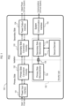
- FIG. 1 is a block diagram conceptually illustrating an example power supply unit (PSU), in the form of PSU 100.
- the PSU 100 may be for use in IT equipment such as a computing device (e.g., server), network device (e.g., network switch), etc.
- the PSU 100 illustrated in FIG. 1 and described below is an example only, and implementations of the PSU 100 may have different numbers and arrangements of the illustrated components and may also include other parts that are not illustrated.
- FIG. 1 is not intended to illustrate specific shapes, dimensions, or other structural details accurately or to scale.
- the PSU 100 comprises a primary side and a secondary side which are galvanically isolated from one another, with the primary side comprising a power input interface 131, primary side conversion circuitry 132, and a primary side microcontroller 140, and with the secondary side comprising secondary side conversion circuitry 133, a power output interface 134, a secondary side microcontroller 150, a system communication interface 155, and a secure element 160.
- the PSU 100 also comprises security logic 165, which executes various operations for enhancing the security of the PSU 100.
- the security logic 165 comprises the secure element 160 together with portions of the internal logic (e.g., programming) of the primary side microcontroller 140 and portions of the internal logic (e.g., programming) of the secondary side microcontroller 150. These components of the PSU 100 will all be described in greater detail in turn below.
- the power input interface 131 is configured to be connected to an external power source, such as a power cord or power bus, to receive input power.
- the power input interface 131 may comprise an electrical socket configured to receive a connector (e.g., plug) of a power cord.
- a connector e.g., plug
- Other types of power input interfaces are well known to those of ordinary skill in the art and any such input interface may be used as the power input interface 131.
- the power output interface 134 is configured to be connected to one or more components of an electronic system, such as to the main system board (e.g., motherboard) of a computing device or networking device, to supply output power to the electronic system.
- the power output interface 134 may comprise a PCB edge-connector (also sometimes called a PCB gold-finger connector) configured to be removably inserted into a complementary socket of the main system board.
- the power output interface 134 may comprise one or more power cables and/or sockets to receive a power cable, with such cables being connected to complementary sockets on the main system board.
- the power output interface 134 may comprise pins configured to mate with complementary sleeves attached to the main system board.
- Other types of power output interfaces are well known to those of ordinary skill in the art and any such output interface may be used as the power output interface 134.
- FIG. 1 The general path of electrical power flowing between the input power and the output power is indicated in FIG. 1 using dash-lined arrows, while analog or digital communication channels are illustrated in FIG. 1 using solid-lined arrows.
- the electrical power pathways illustrated in FIG. 1 are general and not intended to be exhaustive. In practice, there may be multiple different electrical power circuits (also called “rails") (not illustrated) that carry multiple different power signals (e.g., a 12V main system power signal, a 3.3V "standby" power signal, etc.) along various paths.
- electrical power is also provided from the conversion circuitry 132 and/or 133 to the other components of the PSU 100 (such as the microcontrollers 140 and 150 and secure element 160) via one or more such rails.
- the system communication interface 155 comprises a communication channel that is or can be communicably connected to one or more other components of the remainder of the electronic system, such as to a system controller (e.g., baseboard management controller (BMC) or other similar device), to allow for communications to be passed between the PSU 100 and the remainder of the system.
- a system controller e.g., baseboard management controller (BMC) or other similar device
- the system communication interface 155 may comprise a PCB edge connector configured to be received in a complementary socket of the system (e.g., a socket on the main system board).
- the system communication interface 155 may comprise one or more communication cables and/or connectors for receiving communications cables configured to be connected to complementary sockets of the system.
- the system communication interface 155 and the other components of the PSU 100 may utilize the Inter-Integrated Circuit (I2C) (also referred to as IIC or I 2 C) communication protocol (or any of related protocols derivative therefrom, such as SMBus, PMBus, IPMB, TWI, TWSI, I3C, etc.).
- I2C Inter-Integrated Circuit
- other communication protocols are well known to those of ordinary skill in the art (for example, without limitation, SPI, CAN, USB, etc.), and any such communication protocol may be used by the system communication interface 155 and other components for communication.
- the system communication interface 155 may, but does not necessarily have to, use the same communication protocol for external communications (e.g., with the system BMC) as is used for internal communications between the components of the PSU 100.
- the system communication interface 155 may further comprise circuitry to convert the communications signals between the protocols, as would be familiar to those of ordinary skill in the art.
- the primary side conversion circuitry 132 and secondary side conversion circuitry 133 may convert the input electrical power received by the power input interface 131 into the output power output by the power output interface 134.
- the primary side conversion circuitry 132 may convert the input power (e.g., mains AC or high-voltage DC) into a bulk DC voltage (e.g., 400 V), which is stored on a so-called bulk capacitor of the primary side conversion circuitry 132, and the secondary side conversion circuitry 133 may convert the bulk voltage into one or more lower voltage DC power signals (e.g., 12V, 3.3V, etc.) suitable for use by the remainder of the electronic system.
- a lower voltage DC power signals e.g., 12V, 3.3V, etc.
- the primary side conversion circuitry 132 and the secondary side conversion circuitry 133 may be isolated from one another so that no current directly flows therebetween, but they may be coupled inductively-for example, the secondary side conversion circuitry 133 may comprise a transformer (not shown) that inductively couples the two circuits.
- the primary and secondary side conversion circuitries 132 and 133 may also comprise additional elements, such as passive and/or active overcurrent and/or overvoltage protection elements (e.g., a fuse, a transorb, etc.), power factor correction circuitry, and so on. Conversion circuitry of a PSU is familiar to those of ordinary skill in the art, and thus detailed description of these aspects of the primary and secondary conversion circuitries 132 and 133 is omitted herein.
- the primary side conversion circuitry 132 may be controlled by the primary side microcontroller 140 and the secondary side conversion circuitry 133 may be controlled by the secondary side microcontroller 150 (collectively referred to as microcontrollers 140 and 150).
- the microcontrollers 140 and 150 may each comprise processing circuitry (e.g., a processor) and data storage circuitry (e.g., flash memory), as well as firmware stored in the data storage circuitry that can be executed by the processing circuitry to cause performance of the various operations of the microcontrollers 140 and 150.
- Power microcontrollers in general are well known to those of ordinary skill in the art, and in particular those of ordinary skill in the art would be familiar with the configuration of such power microcontrollers to control operations of power conversion circuitry, and thus further detailed description of these aspects of the microcontrollers 140 and 150 is omitted herein. Although only two microcontrollers 140 and 150 are illustrated, in practice the PSU 100 may have any number of microcontrollers equal to or greater than two.
- the secondary side microcontroller 150 is communicably connected to the system communication interface 155, but the primary side microcontroller 140 is not. Therefore, in these examples, messages between the primary side microcontroller 140 and the external system are routed through the secondary side microcontroller 150. Because the primary side microcontroller 140 and the secondary side microcontroller 150 are electrically isolated from one another, they communicate with one another via an isolator 158 disposed therebetween (an isolator may also be referred to as a coupler). The isolator 158 is a device which maintains galvanic isolation between two terminals thereof while allowing information to be passed therebetween.
- an isolator is an opto-isolator (also called an opto-coupler) which uses light to pass information between the two electrically isolated sides. Any other type of isolator (coupler) may be used as the isolator 158.
- the secondary microcontroller 150 is communicably connected directly to the system communication interface 155 but the others are not. Thus, in such examples, communications between the other microcontrollers and the external system are passed through the secondary side microcontroller 150.
- the microcontrollers 140 and 150 may also have additional programming configured to cause the microcontrollers 140 and 150 to perform operations related to enhancing the security of the PSU 100. This additional programming of the microcontrollers 140 and 150 for security operations, together with the secure element 160, forms the security logic 165 mentioned above.
- logic refers to dedicated hardware, software instructions (including firmware) stored in memory and coupled with a processor capable of executing the instructions, or some combination of these.
- the security logic 165 comprises instructions stored in the microcontrollers 140 and 150 (e.g., as part of the firmware thereof) and/or in the secure element 160 and executable by processors thereof to cause various operations described herein to be performed, dedicated hardware configured to perform (or facilitate the performance of) the operations, or some combination of these.
- the microcontrollers 140 and 150 may be formed from commercially available PSU microcontrollers which have been further programmed with additional instructions corresponding to security logic 165. The operations associated with security logic 165 are described in greater detail below in relation to FIGs. 2-9 .
- the secure element 160 comprises a secure, tamper-resistant device (e.g., chip, microcontroller, etc.) that is configured to securely store sensitive cryptographic information, such as keys and certificates, and to perform cryptographic functions, such as key provisioning and digital signature authentication.
- the secure element 160 may be configured to store the cryptographic information in a way that makes it difficult or infeasible for an attacker to obtain the information, even if the attacker obtains physical control over the secure element 160 (for example, by the secure element 160 physically destroying the memory holding the information in response to an unauthorized physical intrusion).
- Various commercially available secure elements exist, which may be used as the secure element 160.
- secure elements that could be used as the secure element 160 include the STSAFEA110 produced by ST, the TA100 produced by Microchip, or other similar secure elements produced by a multiplicity of other vendors.
- the secure element 160 may be configured to perform various operations as part of the security logic 165, as described in greater detail below in relation to FIGs. 2-9 .
- the secure element 160 is disposed on the secondary side of the PSU 100 and is communicably connected to the secondary side microcontroller 160. Moreover, the secure element 160 is not coupled directly to the system communication interface 155, and thus does not communicate directly with the external system. Instead, communications between the external system and the secure element 160 may be routed through the secondary side microcontroller 150 (or through one of the secondary microcontrollers if more than one are present). Furthermore, the secure element 160 is not coupled directly to the primary side microcontroller 140 (or to other primary or secondary microcontrollers if more than two microcontrollers are present), but is instead connected just to the secondary microcontroller 150. Thus, communications between the primary microcontroller 140 (or any other microcontrollers, if more are present) and the secure element 160 may also be routed through the directly connected secondary side microcontroller 150.
- the secure element 160 is disposed on the secondary side and coupled to the secondary microcontroller 150
- the secure element 160 is disposed on the primary side and is connected to the primary side microcontroller 140.
- security operations described herein e.g., in relation to FIGs. 2-9
- the secondary microcontroller may continue to forward information received from the external system to the primary microcontroller and/or secure element, regardless of which side the secure element is part of).
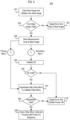
- the methods 200 through 900 may be performed by, or using, various implementations of the PSU 100; specifically, methods 200 through 900 comprises various operations which the microcontrollers 140 and 150 and/or the secure element 160 may be configured to perform in various implementations of the PSU 100.
- the microcontrollers 140 and 150 and/or the secure element 160 may be configured to perform these operations by virtue of corresponding computer program instructions being stored in the microcontrollers 140 and 150 and/or the secure element 160, and/or by virtue of dedicated hardware for performing the operations being provided therein.
- various combinations of these operations, when instantiated in the microcontrollers 140 and 150 and/or the secure element 160 in the form of stored instructions and/or dedicated hardware constitute example configurations of the security logic 165.
- methods 200 to 900 are not mutually exclusive, and the example implementations of the PSU 100 and security logic 165 reflected in the methods 200 to 900 are also not mutually exclusive.
- many of the methods reflect specific example implementations of operations of the other methods.
- two methods may reflect generally similar subject matter but set forth at different levels of generality, with one of the methods being more general and another method being one specific example of some part of the more general method.
- the method 400 of FIG. 4 comprises an example implementation of operations 262 and 263 in method 200 of FIG. 2
- the methods 800 and 900 of FIGs. 8 and 9 comprise example implementations of operations 264 and 265 in the method 200.
- the initialism SE is used to refer to the secure element 160 and the abbreviations "micro,” “Sec.,” and “Pri.” are used to refer to microcontroller, secondary, and primary, respectively.
- Sequence A comprises operations 262 and 263.
- Sequence B comprises operations 264 and 265.
- Some examples of method 200 comprise sequence A, other examples comprise sequence B, and still others comprise both sequences A and B.
- some example implementations of the security logic 165 comprise computer program instructions and/or hardware corresponding to sequence A, other example implementations of the security logic 165 comprise computer program instructions and/or hardware corresponding sequence B, and still other example implementations of the security logic 165 comprise computer program instructions and/or hardware corresponding to both sequence A and sequence B.
- sequences A and B may be performed in any order (including concurrently).
- operation 262 comprises, at power on (i.e., at initiation of a power on sequence), validating the secure element (e.g., secure element 160) and each of the PSU microcontrollers (e.g., primary and secondary microcontrollers 140 and 150) based at least in part on cryptographic information shared by the secure element and each of the microcontrollers.
- this shared cryptographic information may include the pairing information described above in relation to operation 261.
- this shared cryptographic information may be information generated based on the pairing information, such as a message authentication code (MAC) generated based on the pairing information.
- this shared cryptographic information may be a random number generated by the secure element and shared with the microcontrollers.
- MAC message authentication code
- each microcontroller may validate each of the other microcontrollers, and the microcontroller that is directly connected to the secure element (e.g., the secondary microcontroller 150) may validate the secure element.
- the secure element may validate the microcontroller that is directly connected to it (e.g., the secondary microcontroller 150). In this manner, all of the components that make up the security logic are validated by at least one other of the components.
- the validating performed by the microcontrollers and secure element as part of operation 262 includes validating the identities of the microcontrollers and secure element.
- validating the identities of the microcontrollers and secure element means verifying that these components are part of the same group of components which were previously paired together (as described in relation to operation 261).
- This validation may comprise, for example, the microcontrollers and secure element sharing cryptographic information with one another which only the paired components should have access to.
- This cryptographic information may comprise, or may be generated based upon, the pairing information.
- the validating performed by the microcontrollers and secure element as part of operation 262 includes validating that the firmware of the microcontrollers has not been changed.
- the microcontrollers may take actions to validate their own firmware. One example implementation of this is found in method 500 illustrated in FIG. 5 and described below.
- the microcontrollers may validate one another's firmware. One example implementation of this is found in method 700 illustrated in FIG. 7 and described below.
- the validation performed as part of operation 262 may include validating the identity of the other components or validating the firmware of the microcontrollers. In some examples, both of these types of validation are performed together as part of validation of operation 262. In other words, validating the components could include validating their identity, validating their firmware, or both.
- operation 262 is performed at power on. More specifically, this means that operation 262 is performed by the primary and secondary microcontrollers and by the secure element in response to a power on sequence being initiated.
- the power on sequence is a process performed by the PSU, under the direction of the microcontrollers, in response to being turned on.
- main system power is not yet supplied by the PSU to the system.
- the PSU microcontrollers are powered on via auxiliary power carried on an auxiliary rail (also called a standby rail in some systems), which is automatically generated by the PSU and used to power the microcontrollers.
- this auxiliary power is not generated prior to the initiation of the power on sequence, and the power on sequence begins automatically when this auxiliary power starts to be generated.
- the microcontrollers may be configured to automatically start the power on sequence in response to first receiving input power after having been powered off. For example, if the PSU was previously not receiving any input power and then starts receiving input power, the auxiliary power may start being generated automatically from the input power, which turns on the microcontrollers and causes them to begin the power on sequence.
- the power on sequence may begin in response to some other input, such as an on button being pressed, and in some cases auxiliary power is already being generated prior to the beginning of the power on sequence (e.g., in some cases, auxiliary power may continue to be generated even when the system is off).
- the microcontrollers are operational and begin performing various processes to prepare the PSU to supply main system power and to ensure everything is in order, and only upon completion of the power on sequence is main system power supplied by the PSU to the system.
- Sequence A of method 200 further comprises operation 263.
- Operation 263 comprises making completion of the power on sequence (and hence the supply of main system power to the external system) conditional on the successful validation of each of the microcontrollers and the secure element in operation 262. More specifically, operation 263 includes allowing the power on sequence to complete if (i.e., on the condition that) all of the microcontrollers and the secure element are successfully validated in operation 262, and preventing the completion of the power on sequence if (i.e., on the condition that) any one of the microcontrollers and the secure element is not validated in operation 262.
- an error may be signaled by the microcontrollers (e.g., an error flag may be set) if any one of the microcontrollers and the secure element is not validated in operation 262.
- the secure element may refuse to respond to authenticate requests from the system, and thus the system may raise its own error signal as a result.
- operation 264 comprises, in response to a microcontroller receiving (e.g., from the external system) a new firmware image for updating the microcontroller's firmware, using the secure element to validate the new firmware image.
- the secure element may have been provisioned with certificates and/or other system cryptographic information, and the secure element may use this system cryptographic information to validate the firmware image.
- the firmware image may be accompanied by a signature, and in operation 264 the microcontroller that receives the new firmware update may forward information about the firmware update (including the signature) to the secure element and ask the secure element to verify its authenticity.
- the secure element may validate the signature and respond to the microcontroller with the results.
- Example implementations of operation 264 are found in methods 800 and 900 illustrated in FIGs. 8 and 9 and described below.
- Sequence B of method 200 further comprises operation 265.
- Operation 265 comprises making acceptance of the received firmware update conditional on the successful validation of the new firmware image by the secure element in operation 264. More specifically, this means that if the secure element indicates the signature is valid, then the microcontroller accepts the firmware update, but if the secure element indicates the signature is invalid, then the microcontroller discards the firmware image.
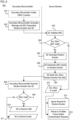
- Method 300 is one example of how the microcontrollers and secure element of a PSU may be provisioned and paired together in operation 261 of method 200.
- Method 300 may be performed in a secure environment by trusted entities, such as at the factory during manufacture/assembly of the PSU.
- Method 300 begins at operation 301, which comprises programming the microcontrollers and provisioning the secure element.
- Programing the microcontrollers may be done, for example, via debug or programming pins thereof, and may include loading firmware images to the microcontroller and/or setting parameters or other configuration settings.
- the microcontrollers are capable of preventing access to their memory via external means, for example by disabling their debug/programming pins, and in some examples the microcontrollers may be commanded to carry out the disabling of the debug/programming pins after the initial programing is completed.
- operation 302 comprises pairing the microcontrollers and secure element with one another.
- the pairing process may vary. However, one example of the paring process of operation 302 is illustrated in operations 304 to 309.
- Operation 304 comprises the secure element generating keys, which form the pairing information described above, using a cryptographic key generation algorithm included in the secure element.
- these keys are shared by the secure element with the secondary microcontroller connected directly to the secure element, and the secure element and secondary microcontroller each stores a copy of the key. Note that while the microcontrollers generally do not have sufficient storage space to store all the keys that may be needed for security, the generally do have sufficient storage space to store one or a few keys, and it is generally not a problem for the microcontrollers to store the pairing key.
- Operation 306 comprises the secure element and secondary microcontroller validating the pairing. This may comprise, for example, the microcontroller and the secure element each generating a MAC based on the pairing key and sending the MAC to the other component, and if each received MAC is valid then this indicates the pairing was successful. If the pairing was unsuccessful, then an error may be indicated and a new pairing may be attempted. If the pairing was successful, then the process continues to operations 307 and 308, which may be performed concurrently or in any order.
- the security level of the secure element is increased, which results in the secure element no longer accepting communications or commands that do not have a valid MAC (a MAC generated based on the pairing key).
- a valid MAC a MAC generated based on the pairing key
- the secondary microcontroller sends a copy of the key to the primary microcontroller (or to each of the other microcontrollers if more are present).
- the primary microcontroller (or other microcontrollers) store the copy of the key.
- the primary microcontroller and secondary microcontroller validate the pairing in a similar manner as in operation 306.
- operation 303 comprises providing the secure element with system cryptographic information that the secure element may need in order to perform its various functions.
- This cryptographic information may comprise keys, certificates, or other information used by the external system (e.g., BMC) for authentication.
- firmware updates provided by the system may be accompanied by a signature, and the secure element may require keys and/or certificates in order to authenticate this signature, and such keys/certificates may be part of the system cryptographic information that is provided to the secure element in operation 303.
- the system may perform its own authentication of the PSU (and other components of the system) upon startup to ensure that counterfeit components are not present, to detect unauthorized changes to configurations or settings, and/or to detect other threats, and the secure element may be given the responsibility of responding to authentication requests from the system.
- the system cryptographic information may also include information (e.g., keys, certifications, etc.) that may be needed in order to facilitate this system authentication of the PSU.
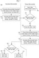
- method 400 comprises a specific example of operations 262 and 263 of method 200. That is, method 400 comprises one example of the microcontrollers and secure element being validated.
- the validation comprises validation of the identity of the components.
- the secondary microcontroller that is directly connected to the secure element validates the identity of the secure element.
- This validation may comprise, for example, the secondary microcontroller sending the secure element a message with a MAC generated based on the microcontroller's stored version of the shared pairing key, and the secure element returning a message with a MAC generated based on the secure element's stored version of the shared pairing key.
- the communications from the secondary microcontroller to the secure element as part of the validation thereof may also be simultaneously used by the secure element to concurrently validate the secondary microcontroller.
- the secure element is configured to require valid MACs for each received communication/command, and thus whenever the secondary microcontroller communicates with the secure element the secure element may validate the microcontroller using these MACs. This will be described in greater detail below in relation to operation 407.
- the microcontroller may then determine if the secure element is valid by determining whether a returned MAC sent by the secure element matches a MAC derived by the microcontroller from the same return message and the stored key.
- the microcontroller determines that the secure element is valid and the process goes down the "Yes” branch to operation 404. If, on the other hand, the returned MAC does not match the expected match, then the microcontroller determines that the secure element is invalid and the process goes down the "No" branch to operation 403.
- the microcontroller signals that an error has occurred and disables the completion of the power on sequence. This operation may be reached, for example, when one of the microcontrollers or the secure element is not part of the original group of paired device-i.e., when one of the originally paired devices has been replaced with an imposter or counterfeit device.
- the other microcontrollers all validate one another's identities. For example, assuming for ease of description that there are just two microcontrollers (i.e., primary and secondary microcontrollers), the secondary microcontroller may send a message with a MAC to the primary microcontroller and the primary microcontroller may responds with a reply message and a reply MAC. In operation 405, each of these microcontrollers may determine whether the other microcontroller is valid by comparing the received MAC to an expected MAC, which the receiving microcontroller derives from the message and the previously stored pairing key.
- the receiving microcontroller determines that the sending microcontroller is not valid and the process continues down the "no" branch to operation 403. If the received MAC does match the expected MAC, the receiving microcontroller determines that the sending microcontroller is valid and the process continues down the "yes" branch to operation 406.
- the microcontrollers all allow the power on sequence to proceed in the normal fashion. This operation is reached only if all of the microcontrollers and the secure element have had their identities successfully validated.
- the secure element validates the identity of the secondary microcontroller. This operation may occur concurrently with operation 401, and may be triggered by the secure element receiving communications from the secondary microcontroller as part of the secondary microcontroller attempting to validate the secure element in operation 401. For example, as noted above the secondary microcontroller may send the secure element a message with a MAC, and in operation 407 the secure element may validate the identity of the secondary microcontroller by avoiding the received MAC based on the shared pairing key.
- the process continues to operation 409 and the secure element prevents the authentication by the system of the PSU.
- This may comprise, for example, the secure element refusing to respond to requests by the system to authenticate the PSU. This will signal to the system controller that there is a problem, and the system controller may signal an error and/or take other protective or corrective actions, such as preventing powering on of other components or commanding a shutdown if power on has already occurred.
- the process continues to operation 410 and the secure element allows and facilities the authentication of the PSU by the system, e.g., by responding to authentication requests from the system.
- the method 500 comprises a specific example of operations 262 and 263 of method 200. That is, method 500 comprises one example of the microcontrollers and secure element being validated.
- the validation comprises the microcontrollers validating their own firmware image, in addition to performing additional validation of the other components.
- Operations 501 through 504 are performed by each of the microcontrollers. After operation 504, the process diverges into sequences C and D depending on which microcontroller is performing the method-the secondary microcontroller which is directly coupled to the secure element follows sequence C, whereas the primary microcontroller (or any other microcontrollers if present) follow sequence D. Sequences C and D reunite at operation 507, and operations 507 through 510 are thus performed by all of the microcontrollers.
- the microcontroller enters its boot image and validates its own main image. This operation is performed in response to the microcontroller being initialized or powered on.
- Each of the microcontrollers may have two distinct firmware images saved in its memory, with one of the images being a boot image comprising a bootloader which the microcontroller automatically executes upon initially booting up (i.e., after being powered on) and the other being the main firmware image that comprises the firmware that is run during normal operation of the microcontroller, with the bootloader causing the main image to be executed after performing some initial operations.
- the boot image is saved in a section of memory that is immutable and which is measurable via hardware to ensure that no alternation to this section of memory has occurred.
- the main firmware image is saved in a different section of memory that can be changed, in order to allow for firmware updates when needed.
- the immutability of the section of memory in which the boot image is stored, in combination with the disabling of the debug/programming pins, ensures that the boot image cannot be changed and allows the bootloader to be a trusted entity which can be relied upon to validate the main firmware image.
- the bootloader is configured to, upon being executed, measure the main firmware image using a cryptographic hashing algorithm, and compare the resulting hash value to an expected hash value (which was previously measured from the main firmware image) to ensure the main firmware has not changed since the last measurement.
- the bootloader determines if the main image is valid based on whether the aforementioned hash values match. If the hash values do not match, then the main image is not valid and the boot loader proceeds down the "No" path to operation 503. If the hash values do match, then the main image is valid and the boot loader proceeds down the "Yes" path to operation 504.
- the bootloader signals an error and stays within the boot image, refraining from launching the main firmware image.
- the bootloader stores the measurement (the hash value) for subsequent comparisons and then jumps to (i.e., executes) the main firmware image.
- the method 500 may diverge down sequences C and D, depending on which microcontroller is performing the method, as noted above.
- operation 505 comprises validating the secure element. This validation may comprise validating the identity of the secure element, similar to operation 401 described above.
- operation 506 if the secure element is determined to be valid, then the process continues down the "Yes" path to operation 507. If the secure element is determined to be invalid, then the process continues down the "No" path to operation 510.
- the microcontroller may signal an error and disable the completion of the power on sequence. Operation 510 is reached when one of the microcontrollers determines the secure element or another one of the microcontrollers to be invalid, and is performed by the microcontroller that made this determination. For example, if the secondary microcontroller determines the secure element to be invalid in operation 506, then operation 510 is performed by the secondary microcontroller. As another example, if the primary microcontroller determines the secondary microcontroller to be invalid in operation 508 (described below), then the primary microcontroller may perform operation 510. Either microcontroller can, on its own, prevent the power on sequence from completing and disable the supply of power to the system.
- each of the microcontroller executes a handshake with the other microcontrollers to validate the other microcontrollers.
- the handshake may include exchanging information, such as MACs, and each of the microcontrollers may determine in operation 508 if the handshake was valid based on the exchanged information. If the handshake was valid (e.g., the received MAC matches an expected MAC), then the method continues down the "Yes" path to operation 509. If the handshake was invalid (e.g., the received MAC does not match the expected MAC), then the method continues down the "No" path to operation 510.
- the microcontroller deems the other microcontroller to be valid, because the handshake was valid. Accordingly, because the other microcontroller was deemed valid, the microcontroller proceeds with allowing the power on sequence to occur.
- a single microcontroller can prevent the power on sequence, and thus the power on sequence will only proceed if both of the microcontrollers decide in operation 509 to proceed with the power on sequence.
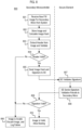
- the method 600 comprises a specific example of operations 401 and 402 of method 400 and of operations 505 and 506 of method 500. That is, method 600 comprises a more specific example of how the secure element may be validated. Some of the operations of the method 600 are performed by the secondary microcontroller that is coupled to the secure element, and others are performed by the secure element, and these operations are separated by the dashed line in FIG. 6 .
- Operation 601 is an optional operation, and thus is indicated in dashing.
- Operation 601 comprises the secondary microcontroller verifying MAC counters.
- Such MAC counters may be counters of the number of MAC-containing messages sent between the secondary microcontroller and the secure element.
- the secondary microcontroller may keep track of this in its own MAC counter, and the secure element may also keep track of this in its own MAC counter, and validating the MAC counters may comprise comparing the two values to see if they match. If the MAC counters match, there is no problem and the process may proceed to operation 602. However, if the MAC counters do now match, some protective or corrective action may be needed.
- the MAC counters not matching could be indicative of malicious activity, and thus, in some examples, the microcontroller may proceed from operation 601 to operation 609 if the MAC counter of the secure element does not match the microcontrollers stored MAC counter.
- the secondary microcontroller In operation 602, the secondary microcontroller generates and sends a message and a corresponding MAC ("first MAC") to the secure element, with the message comprising a request to the secure element for the secure element to generate a random number (the secure element may comprise a random number generator as part of its cryptographic functions).
- the first MAC is generated by the secondary microcontroller based on the message and on the copy of the shared pairing key stored by the secondary microcontroller.
- the secure element validates the first MAC received from the secondary microcontroller. For example, the secure element may generate its own MAC based on the received message and based on the secure element's copy of the pairing key ("second MAC"), and then compare the generated second MAC with the received first MAC.
- second MAC the secure element's copy of the pairing key
- the secure element generates the random number.
- the secure element determines another MAC (“third MAC") based on the random number and using the stored pairing key.
- the secure element sends the secondary microcontroller a message comprising the random number generated in operation 605 together with the corresponding third MAC generated in operation 606.
- the secondary microcontroller receives the message with the random number and third MAC from the secure element.
- the secondary microcontroller determines whether the received third MAC is valid. This may comprise the secondary microcontroller generating another MAC based on the received random number and based on its stored version of the pairing key ("fourth MAC"), and determining whether the received third MAC matches the generated fourth MAC.
- the received third MAC is considered as being valid if it matches the generated fourth MAC, because the only feasible way for the secure element to have generated the same MAC as the microcontroller would be if they both generated the MACs using the same random number and the same key, and if the secure element has the same key as the microcontroller then this indicates it is the same secure element with which the microcontroller was previously paired.
- the process continues to operation 610 in which the microcontroller deems the secure element as being valid.
- the process continues to operation 609 in which the microcontroller deems the secure element as being invalid.
- the secure element In operation 612, which is performed if the first MAC is determined to be invalid in operation 604, the secure element deems the secondary microcontroller to be invalid. Accordingly, the secure element may then perform operations 613 and 614 in any order (including concurrently).
- the secure element ignores the request from the secondary microcontroller to provide the random number.
- the secure element refuses to facilitate the authentication of the PSU by the system controller. For example, the secure element refuses to respond to future requests by the system controller for authentication.
- the method 700 comprises a specific example of operations 404 and 405 of method 400 and of operations 507 and 508 of method 500. That is, method 700 comprises a more specific example of how the microcontroller may validate one another, or in other words a more specific example of a handshake that can be used to validate the microcontrollers.
- the validation of the microcontrollers comprises both a validation of their identity and a validation of their respective main firmware images.
- method 700 may be performed after method 600 has been performed.
- the secondary microcontroller In operation 701, the secondary microcontroller generates a MAC based on a hash of its main firmware image, the random number received from the secure element, and the shared pairing key. In some examples, this random number may be the same random number that was received by the secondary microcontroller in operation 606 of method 600. In some examples, the hash of the main firmware image may have been generated previously, for example in operation 501 of method 500.
- the secondary microcontroller sends a message comprising the hash of its main firmware image and the random number, together with the corresponding MAC, to the primary microcontroller.
- the primary microcontroller determines whether the whether the received hash and MAC are valid.
- the received hash is determined to be valid if it matches an expected hash stored by the primary microcontroller.
- the expected hash corresponds to a hash of the secondary microcontroller's main image which was taken at a previous date and stored by the primary microcontroller (e.g., as part of a previous validation operation).
- the current hash of the main firmware image of the secondary microcontroller may be deemed valid by the primary microcontroller if and only if the main firmware image of the secondary microcontroller has not changed since the last time the primary microcontroller checked it (e.g., since the last power on).
- the MAC is validated in the same way as described above in relation to operation 607, i.e., the primary microcontroller generates another MAC based on the received hash, the random number, and the shared pairing key and determines if the received MAC matches the generated MAC.
- the process continues along the "Yes" path to operation 705, wherein the primary microcontroller deems the secondary microcontroller to be valid (i.e., both the firmware and the identity of the secondary microcontroller are invalid). If, on the other hand, either one of the received Hash or MAC are invalid, then the process continues along the "No" path to operation 704, wherein the primary microcontroller deems the secondary microcontroller to be invalid (i.e., either the firmware, the identity, or both the firmware and the identity of the secondary microcontroller are invalid).
- the primary microcontroller In operation 706, the primary microcontroller generates a MAC based on a hash of its main firmware image, the received random number, and the shared pairing key.
- the hash of the main firmware image may have been generated previously, for example in operation 501 of method 500.
- the primary microcontroller sends a message to the secondary microcontroller comprising the hash, the random number, and the MAC.
- the secondary microcontroller determines whether the main image hash and the MAC it received from the other microcontroller are valid, in the same manner as already described above in relation to operation 703.
- the process continues along the "Yes" path to operation 709, wherein the secondary microcontroller deems the primary microcontroller to be valid. If, on the other hand, either one of the received Hash or MAC are invalid, then the process continues along the "No" path to operation 710, wherein the secondary microcontroller deems the primary microcontroller to be invalid.
- the method 700 corresponds to a "handshake" between the microcontrollers, and this handshake may be valid if both microcontrollers deem the other microcontroller to be valid in operations 709 and 705, whereas the handshake may be invalid if either one of the microcontrollers determines the other microcontroller to be valid.
- the methods 800 and 900 comprise specific examples of operations 264 and 265 of method 200. That is, methods 800 and 900 comprises more specific examples of how the secure element may be used to validate firmware updates received from the system for the microcontrollers.
- Method 800 is an example in which the secondary microcontroller which is connected directly to the secure element is the target of the firmware update
- method 900 is an example in which the primary microcontroller is the target of the firmware update.
- the methods 800 and 900 comprise some similar operations, but because the primary microcontroller is not coupled directly to the secure element additional operations are needed when the primary microcontroller is the target of the update (with most of these additional operations pertaining to the secondary microcontroller forwarding messages between the other components).
- methods 800 and 900 are performed after the microcontrollers and secure element have all been successfully validated, and therefore it can be assumed in these examples that the microcontrollers and secure elements are all trusted entities.
- the secondary microcontroller receives a new firmware image intended for updating the main firmware of the secondary microcontroller, together with an accompanying signature.
- This new firmware image may be received from the external system (e.g., from the BMC) via the system communication interface 155.
- the firmware update is genuine merely because it is received from the external system, as it may be possible in some cases that the external system is itself compromised.
- an important function of the secure element in some examples may be to validate any new firmware updates based on system cryptographic information that was provided to the secure element at pairing (e.g., in operation 303 of method 300).
- the secondary microcontroller in response to determining that the new firmware image is intended for the secondary microcontroller, stores the firmware image and calculates a hash of the image.
- the secondary microcontroller extracts the header from the image and validates the header.
- the process continues down the "yes" branch to operation 805, which results in further validation of the entire image being performed using the secure element in operations 805 through 810. If the header is invalid, the process continues down the "no" branch to operation 806, wherein the microcontroller determines that the firmware image is invalid, discards the image (i.e., does not implement the update and deletes the image), and logs a failure.
- the microcontroller sends the hash of the image and a signature of the image (which accompanied the image sent from the system) to the secure element and requests that the secure element validate the signature.
- the microcontroller also may generate and send a MAC along with the message, with the MAC being generated based on the message and the stored pairing key. This is because, in some examples the secure element is configured to require a valid MACs for each received communication/command.
- the secure element validates the received signature.
- the secure element may, for example, use system cryptographic information (e.g., keys, certificates, etc.) that was previously stored in the secure element to validate the signature.
- system cryptographic information e.g., keys, certificates, etc.
- the performance of operation 807 may be conditional upon the successful validation of a MAC accompanying the request.
- the secure element sends the results of the signature validation to the secondary microcontroller.
- the results of the signature validation may be, for example, an indication of whether the signature is valid or invalid.
- the secondary microcontroller considers the signature validation results and determines whether the signature is valid or invalid based on the signature validation results received from the secure element. If the signature is valid, then the process continues down the "yes" branch to operation 810, wherein the microcontroller determines that the entire image is valid (because the signature is valid) and therefore allows that new image to be booted into and the update process to proceed. If the signature is invalid, then the process continues down the "no" branch to operation 806, which was described above.
- the process is similar to the method 800 except that the firmware update is intended for the primary microcontroller and the secondary microcontroller acts as an intermediary between the secondary microcontroller, the system, and the secure element.
- the secondary microcontroller receives, from the external system (e.g., BMC), a new firmware image which is intended for updating the firmware of the primary microcontroller, together with an accompanying signature.
- the external system e.g., BMC
- the secondary microcontroller in response to determining that the firmware update is for the primary microcontroller, forwards the new firmware image (and accompanying signature) to the primary microcontroller.
- the primary microcontroller stores the image, calculates a hash thereof, extracts a header from the image, and validates the header. These operations are similar to the operations 802 to 804 in method 800.
- operation 905 If it is determined in operation 905 that the header is invalid, the process continues to operation 906. If the header is valid, the process continues to operation 907.
- operation 907 the primary microcontroller sends the image hash and the signature to the secondary microcontroller. Operation 907 is similar to operation 805, except that in operation 907 the hash and signature are not sent directly to the secure element because the primary microcontroller is not connected directly thereto, and thus the message is instead sent to the secondary microcontroller.
- the secondary microcontroller forwards the received hash and signature on to the secure element and requests that the secure element validate the signature.
- the secondary microcontroller may recognize that it needs to forward the message to the secure element based on the type of message or based on an instruction included with the message.
- the microcontroller also may generate and send a MAC along with the message, with the MAC being generated based on the message and the stored pairing key. This is because, in some examples the secure element is configured to require a valid MACs for each received communication/command.
- operations 909 and 910 the secure element validates the signature and sends the results to the secondary microcontroller. These operations are similar to operations 807 and 808 of method 800. Although not illustrated, in some examples, the performance of operation 909 and 910 may be conditional upon the successful validation of a MAC accompanying the request.
- the secondary microcontroller forwards the results of the signature validation to the primary controller.
- the primary microcontroller determines whether the signature is valid based on the received signature validation results, and either discards the image if the signature is invalid (operation 906) or allows the image to be booted and the update to proceed if the signature is valid (operation 913). These operations are similar to operations 809, 806, and 810 of method 800.
- the method 900 may also be performed by other microcontrollers besides the primary microcontroller.
- the method 900 may be used to validate a firmware update for any microcontroller other than the secondary microcontroller that is directly connected to the secure element.
- additional secondary microcontrollers if any are present
- the references in FIG. 9 to "primary microcontroller” should be understood as referring, mutatis mutandis, to this additional secondary microcontroller and the references to the "secondary microcontroller” should be understood as referring to the one secondary microcontroller that is directly connected to the secure element.
- an item means to have possession of and/or control over the item. This may include, for example, forming (or assembling) the item from its constituent materials and/or obtaining possession of and/or control over an already-formed item.
Landscapes
- Engineering & Computer Science (AREA)
- Theoretical Computer Science (AREA)
- Computer Security & Cryptography (AREA)
- Computer Hardware Design (AREA)
- Software Systems (AREA)
- General Engineering & Computer Science (AREA)
- Physics & Mathematics (AREA)
- General Physics & Mathematics (AREA)
- Health & Medical Sciences (AREA)
- Bioethics (AREA)
- General Health & Medical Sciences (AREA)
- Power Sources (AREA)
Applications Claiming Priority (1)
| Application Number | Priority Date | Filing Date | Title |
|---|---|---|---|
| US18/329,118 US12400043B2 (en) | 2023-06-05 | 2023-06-05 | Security for power supply unit microcontrollers |
Publications (2)
| Publication Number | Publication Date |
|---|---|
| EP4485253A2 true EP4485253A2 (de) | 2025-01-01 |
| EP4485253A3 EP4485253A3 (de) | 2025-03-12 |
Family
ID=91376804
Family Applications (1)
| Application Number | Title | Priority Date | Filing Date |
|---|---|---|---|
| EP24180042.4A Pending EP4485253A3 (de) | 2023-06-05 | 2024-06-04 | Sicherheit für mikrosteuerungen einer stromversorgungseinheit |
Country Status (4)
| Country | Link |
|---|---|
| US (1) | US12400043B2 (de) |
| EP (1) | EP4485253A3 (de) |
| CN (1) | CN119089445B (de) |
| TW (1) | TW202450219A (de) |
Families Citing this family (1)
| Publication number | Priority date | Publication date | Assignee | Title |
|---|---|---|---|---|
| JP2024104875A (ja) * | 2023-01-25 | 2024-08-06 | キオクシア株式会社 | メモリシステムおよび制御方法 |
Citations (1)
| Publication number | Priority date | Publication date | Assignee | Title |
|---|---|---|---|---|
| US20150273610A1 (en) * | 2014-03-28 | 2015-10-01 | Illinois Tool Works Inc. | Systems and methods for pairing of wireless control devices with a welding power supply |
Family Cites Families (8)
| Publication number | Priority date | Publication date | Assignee | Title |
|---|---|---|---|---|
| US9953166B2 (en) | 2013-07-04 | 2018-04-24 | Microsemi SoC Corporation | Method for securely booting target processor in target system using a secure root of trust to verify a returned message authentication code recreated by the target processor |
| US10613567B2 (en) * | 2013-08-06 | 2020-04-07 | Bedrock Automation Platforms Inc. | Secure power supply for an industrial control system |
| FR3043228B1 (fr) * | 2015-11-03 | 2018-03-30 | Proton World International N.V. | Demarrage controle d'un circuit electronique |
| CN109150390A (zh) * | 2018-06-05 | 2019-01-04 | 捷德(中国)信息科技有限公司 | 一种基于spi通讯接口的嵌入式安全元件 |
| US10983785B1 (en) * | 2018-06-28 | 2021-04-20 | Amazon Technologies, Inc. | Firmware updating of power units |
| CN108810418B (zh) | 2018-07-16 | 2020-09-11 | Oppo广东移动通信有限公司 | 图像处理方法、装置、移动终端及计算机可读存储介质 |
| PT3680797T (pt) * | 2019-01-14 | 2022-02-02 | MUSE Electronics GmbH | Dispositivo de processamento de dados protegido contra manipulação |
| EP3722979B1 (de) * | 2019-04-12 | 2022-06-01 | Nxp B.V. | Authentifizierung einer stromversorgung an einen mikrocontroller |
-
2023
- 2023-06-05 US US18/329,118 patent/US12400043B2/en active Active
-
2024
- 2024-06-04 TW TW113120683A patent/TW202450219A/zh unknown
- 2024-06-04 EP EP24180042.4A patent/EP4485253A3/de active Pending
- 2024-06-05 CN CN202410724351.0A patent/CN119089445B/zh active Active
Patent Citations (1)
| Publication number | Priority date | Publication date | Assignee | Title |
|---|---|---|---|---|
| US20150273610A1 (en) * | 2014-03-28 | 2015-10-01 | Illinois Tool Works Inc. | Systems and methods for pairing of wireless control devices with a welding power supply |
Also Published As
| Publication number | Publication date |
|---|---|
| US20240403496A1 (en) | 2024-12-05 |
| TW202450219A (zh) | 2024-12-16 |
| CN119089445B (zh) | 2026-03-17 |
| US12400043B2 (en) | 2025-08-26 |
| CN119089445A (zh) | 2024-12-06 |
| EP4485253A3 (de) | 2025-03-12 |
Similar Documents
| Publication | Publication Date | Title |
|---|---|---|
| CN111008379B (zh) | 电子设备的固件安全检测方法及相关设备 | |
| CN113168474B (zh) | 固件的安全验证 | |
| EP3291087A1 (de) | Vorrichtung und zugehöriges verfahren zur authentifizierung von firmware | |
| US12231582B2 (en) | Method for attestation of an electronic component on a circuit board | |
| EP4485253A2 (de) | Sicherheit für mikrosteuerungen einer stromversorgungseinheit | |
| US20210064734A1 (en) | Cross authentication method for computer system security | |
| CN111813010B (zh) | 微控制器以及电源 | |
| US20170046513A1 (en) | Firmware authentication | |
| CN112149066A (zh) | 软件的激活验证方法和装置 | |
| US10863602B2 (en) | Methods and apparatus for detecting connection or disconnection of an auxiliary load to a driver | |
| US9177123B1 (en) | Detecting illegitimate code generators | |
| CN110750794B (zh) | 一种bios安全启动方法及系统 | |
| CN120744931A (zh) | 一种基于安全可信模组加密认证的设备启动方法及装置 | |
| CN206649517U (zh) | 服务器可信平台度量控制系统及包括该系统的服务器 | |
| CN108629185B (zh) | 服务器可信平台度量控制系统及其运行方法 | |
| CN114844727A (zh) | 交换机及其防护电路、防护系统 | |
| US20260087180A1 (en) | Security module validation | |
| AU2022476511A1 (en) | Confirmation method, confirmation device, power storage device, confirmation system, program and computer readable medium | |
| US11579995B2 (en) | Electronic element, system comprising such an electronic element and method for monitoring and cutting off a processor on occurrence of a failure event | |
| US20240411887A1 (en) | Installation control device, installation control method, sharing system, sharing method, and storage medium | |
| US11650558B2 (en) | Method and device for checking the integrity of modules of a wind turbine | |
| CN114762215A (zh) | 用于光学无线功率系统的双向安全接口 | |
| JP7810338B2 (ja) | 電池パックおよびそのファームウェアのアップデート方法 | |
| KR102540451B1 (ko) | 사물인터넷 디바이스 보안부팅 시스템 및 이를 이용한 사물인터넷 디바이스 보안부팅 방법 | |
| KR102916570B1 (ko) | 배터리 팩 및 이의 펌웨어 업데이트 방법 |
Legal Events
| Date | Code | Title | Description |
|---|---|---|---|
| PUAI | Public reference made under article 153(3) epc to a published international application that has entered the european phase |
Free format text: ORIGINAL CODE: 0009012 |
|
| STAA | Information on the status of an ep patent application or granted ep patent |
Free format text: STATUS: THE APPLICATION HAS BEEN PUBLISHED |
|
| AK | Designated contracting states |
Kind code of ref document: A2 Designated state(s): AL AT BE BG CH CY CZ DE DK EE ES FI FR GB GR HR HU IE IS IT LI LT LU LV MC ME MK MT NL NO PL PT RO RS SE SI SK SM TR |
|
| PUAL | Search report despatched |
Free format text: ORIGINAL CODE: 0009013 |
|
| AK | Designated contracting states |
Kind code of ref document: A3 Designated state(s): AL AT BE BG CH CY CZ DE DK EE ES FI FR GB GR HR HU IE IS IT LI LT LU LV MC ME MK MT NL NO PL PT RO RS SE SI SK SM TR |
|
| RIC1 | Information provided on ipc code assigned before grant |
Ipc: G06F 21/57 20130101AFI20250205BHEP |
|
| STAA | Information on the status of an ep patent application or granted ep patent |
Free format text: STATUS: REQUEST FOR EXAMINATION WAS MADE |
|
| STAA | Information on the status of an ep patent application or granted ep patent |
Free format text: STATUS: EXAMINATION IS IN PROGRESS |
|
| 17P | Request for examination filed |
Effective date: 20250912 |
|
| 17Q | First examination report despatched |
Effective date: 20251010 |