EP4485012A2 - Marine sensoren mit geringer querspeisung - Google Patents
Marine sensoren mit geringer querspeisung Download PDFInfo
- Publication number
- EP4485012A2 EP4485012A2 EP24213081.3A EP24213081A EP4485012A2 EP 4485012 A2 EP4485012 A2 EP 4485012A2 EP 24213081 A EP24213081 A EP 24213081A EP 4485012 A2 EP4485012 A2 EP 4485012A2
- Authority
- EP
- European Patent Office
- Prior art keywords
- sensor
- enclosure
- sensing elements
- output node
- positive
- Prior art date
- Legal status (The legal status is an assumption and is not a legal conclusion. Google has not performed a legal analysis and makes no representation as to the accuracy of the status listed.)
- Pending
Links
Images







Classifications
-
- G—PHYSICS
- G01—MEASURING; TESTING
- G01V—GEOPHYSICS; GRAVITATIONAL MEASUREMENTS; DETECTING MASSES OR OBJECTS; TAGS
- G01V1/00—Seismology; Seismic or acoustic prospecting or detecting
- G01V1/02—Generating seismic energy
- G01V1/159—Generating seismic energy using piezoelectric or magnetostrictive driving means
-
- G—PHYSICS
- G01—MEASURING; TESTING
- G01H—MEASUREMENT OF MECHANICAL VIBRATIONS OR ULTRASONIC, SONIC OR INFRASONIC WAVES
- G01H11/00—Measuring mechanical vibrations or ultrasonic, sonic or infrasonic waves by detecting changes in electric or magnetic properties
- G01H11/06—Measuring mechanical vibrations or ultrasonic, sonic or infrasonic waves by detecting changes in electric or magnetic properties by electric means
- G01H11/08—Measuring mechanical vibrations or ultrasonic, sonic or infrasonic waves by detecting changes in electric or magnetic properties by electric means using piezoelectric devices
-
- G—PHYSICS
- G01—MEASURING; TESTING
- G01V—GEOPHYSICS; GRAVITATIONAL MEASUREMENTS; DETECTING MASSES OR OBJECTS; TAGS
- G01V1/00—Seismology; Seismic or acoustic prospecting or detecting
- G01V1/16—Receiving elements for seismic signals; Arrangements or adaptations of receiving elements
- G01V1/18—Receiving elements, e.g. seismometer, geophone or torque detectors, for localised single point measurements
- G01V1/186—Hydrophones
-
- G—PHYSICS
- G01—MEASURING; TESTING
- G01V—GEOPHYSICS; GRAVITATIONAL MEASUREMENTS; DETECTING MASSES OR OBJECTS; TAGS
- G01V1/00—Seismology; Seismic or acoustic prospecting or detecting
- G01V1/16—Receiving elements for seismic signals; Arrangements or adaptations of receiving elements
- G01V1/20—Arrangements of receiving elements, e.g. geophone pattern
- G01V1/201—Constructional details of seismic cables, e.g. streamers
-
- G—PHYSICS
- G01—MEASURING; TESTING
- G01V—GEOPHYSICS; GRAVITATIONAL MEASUREMENTS; DETECTING MASSES OR OBJECTS; TAGS
- G01V2210/00—Details of seismic processing or analysis
- G01V2210/10—Aspects of acoustic signal generation or detection
- G01V2210/14—Signal detection
- G01V2210/142—Receiver location
- G01V2210/1427—Sea bed
Definitions
- Cross feed is a term used to describe the effect of an electrical signal in one channel undesirably coupling into another channel via a parasitic impedance that exists between them.
- Cross feed can occur within marine seismic sensor systems such as those in seismic streamers, ocean bottom cables, or ocean bottom nodes.
- voltage and/or current fluctuations in power supply lines, telemetry lines, control lines, or any auxiliary lines can electrically couple into seismic sensor channels and thus mask the small seismic signal voltages that are generated by the seismic sensors.
- differential amplifiers To combat cross feed in marine seismic sensor systems, differential amplifiers have been employed in conjunction with unscreened, twisted-pair conductors that couple the small signals from the seismic sensors to the inputs of the differential amplifier.
- the output of a perfect differential amplifier is equal to the difference between the signals presented at its two inputs, and each conductor in a tightly twisted pair of almost identical conductors will have almost identical parasitic impedance to any point in space.
- the intention in such designs has been that any undesirable cross feed signals will be induced identically in each of the twisted pair's conductors so that identical "common mode" cross feed signals are presented at each input of the differential amplifier.
- the output of the differential amplifier is proportional to the difference between the signals at its inputs, the identically induced common mode cross feed signals should effectively cancel and should therefore not appear at the differential amplifier's output.
- phrases "based on” or “based at least in part on” refer to one or more inputs that can be used directly or indirectly in making some determination or in performing some computation. Use of those phrases herein is not intended to foreclose using additional or other inputs in making the described determination or in performing the described computation. Rather, determinations or computations so described may be based either solely on the referenced inputs or on those inputs as well as others.
- the phrase “configured to” as used herein means that the referenced item, when operated, can perform the described function. In this sense, an item can be “configured to” perform a function even when the item is not operating and therefore is not currently performing the function.
- Coupled refers to a connection between items. Such a connection can be direct, or can be indirect, such as through connections with other intermediate items.
- Terms used herein such as “including,” “comprising,” and their variants, mean “including but not limited to.”
- Articles of speech such as “a,” “an,” and “the” as used herein are intended to serve as singular as well as plural references except where the context clearly indicates otherwise.
- conductor refers to any type of electrical conductor for conducting electric current in an electronic system.
- a conductor may comprise a metal wire or trace, or may comprise an all-carbon conductor, or may comprise another type of conducting member.
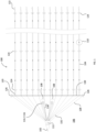
- FIGS. 1 and 2 present top and side views, respectively, of an example towed-streamer marine seismic survey system 100.
- Survey system 100 is representative of a variety of similar geophysical survey systems in which a vessel 102 tows an array of elongate streamers 104 in a body of water 106 such as an ocean, a sea, a bay, or a large lake.
- Vessel 102 is shown towing twelve streamers 104 in the illustrated example.
- any number of streamers may be towed, from as few as one streamer to as many as twenty or more.
- Embodiments to be described below have useful application in relation to towed-streamer surveys such as that depicted in FIGS. 1 and 2 . They may also have useful application in other environments in which other types of sensors or sensor cables are used-for example, in environments that use ocean-bottom sensor cables or ocean-bottom nodes.
- the terms "streamer” and "cable” may be used interchangeably below.
- one or more seismic sources 108 are activated to produce acoustic energy 200 that propagates in body of water 106.
- Energy 200 penetrates various layers of sediment and rock 202, 204 underlying body of water 106. As it does so, it encounters interfaces 206, 208, 210 between materials having different physical characteristics, including different acoustic impedances. At each such interface, a portion of energy 200 is reflected upward while another portion of the energy is refracted downward and continues toward the next lower interface, as shown. Reflected energy 212, 214, 216 is detected by sensors 110 disposed at intervals along the lengths of streamers 104. In FIGS. 1 and 2 , sensors 110 are indicated as black squares inside each of streamers 104.
- Sensors 110 produce signals corresponding to the reflected energy. These signals are collected and recorded by control equipment 112 located onboard vessel 102. The recorded signals may be processed and analyzed onboard vessel 102 and/or at one or more onshore data centers to produce images of structures within subsurface 218. These images can be useful, for example, in identifying possible locations of hydrocarbon reservoirs within subsurface 218.
- vessel 102 is shown towing a total of two sources 108. In other systems, different numbers of sources may be used, and the sources may be towed by other vessels, which vessels may or may not tow streamer arrays.
- a source 108 includes one or more source subarrays 114, and each subarray 114 includes one or more acoustic emitters such as air guns or marine vibrators.
- Each subarray 114 may be suspended at a desired depth from a subarray float 116. Compressed air as well as electrical power and control signals may be communicated to each subarray via source umbilical cables 118.
- Data may be collected, also via source umbilical cables 118, from various sensors located on subarrays 114 and floats 116, such as acoustic transceivers and global positioning system ("GPS") units. Acoustic transceivers and GPS units so disposed help to accurately determine the positions of each subarray 114 during a survey.
- subarrays 114 may be equipped with steering devices to better control their positions during the survey.
- Streamers 104 are often very long, on the order of 5 to 10 kilometers, so usually are constructed by coupling numerous shorter streamer sections together.
- Each streamer 104 may be attached to a dilt float 120 at its proximal end (the end nearest vessel 102) and to a tail buoy 122 at its distal end (the end farthest from vessel 102).
- Dilt floats 120 and tail buoys 122 may be equipped with GPS units as well, to help determine the positions of each streamer 104 relative to an absolute frame of reference such as the earth.
- Each streamer 104 may in turn be equipped with acoustic transceivers and/or compass units to help determine their positions relative to one another.
- streamers 104 include steering devices 124 attached at intervals, such as every 300 meters. Steering devices 124 typically provide one or more control surfaces to enable moving the streamer to a desired depth, or to a desired lateral position, or both.
- Paravanes 126 are shown coupled to vessel 102 via tow ropes 128. As the vessel tows the equipment, paravanes 126 provide opposing lateral forces that straighten a spreader rope 130, to which each of streamers 104 is attached at its proximal end. Spreader rope 130 helps to establish a desired crossline spacing between the proximal ends of the streamers. Power, control, and data communication pathways are housed within lead-in cables 132, which couple the sensors and control devices in each of streamers 104 to the control equipment 112 onboard vessel 102.
- the array of streamers 104 forms a sensor surface at which acoustic energy is received for recording by control equipment 112.
- an inclined and/or fan shaped receiving surface may be desired and may be implemented using control devices on the streamers such as those just described.
- Other array geometries may be implemented as well.
- Prevailing conditions in body of water 106 may cause the depths and lateral positions of streamers 104 to vary at times, of course.
- streamers 104 need not all have the same length and need not all be towed at the same depth or with the same depth profile.
- FIG. 3 illustrates an example ocean bottom cable survey system 300, in which a vessel 102 tows one or more sources 108 over an installation of one or more ocean bottom cables 302, each of which is disposed on a water bottom 304.
- Each cable 302 may include one or more sensors or sensor groups 110 disposed along its length, generally as shown.
- each of the cables may be coupled to a manifold 306 in which signals from the sensors may be aggregated and either stored or transmitted to a collection point, or both.
- FIG. 4 illustrates an example ocean bottom node survey system 400, in which a vessel 102 tows one or more sources 108 over an installation of one or more ocean bottom nodes 402, each of which is disposed on a water bottom 404.
- Each node 402 may include one or more sensors or sensor groups 110 as shown. Signals generated by the sensors or sensor groups may be collected in the nodes for later retrieval, or may be transmitted to a collection point, or both.
- passive acoustic energy may be used to perform the survey either in lieu of or in addition to acoustic energy generated by active seismic sources such as sources 108.
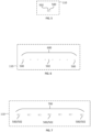
- FIGS. 5, 6, and 7 illustrate several example arrangements consistent with embodiments for disposing sensors 110 in a streamer or cable 104 or in an ocean bottom node 402 or an ocean bottom cable 302.
- pressure sensors are indicated with white squares
- motion sensors are indicated with shaded squares.
- each sensor location 110 comprises a single pressure sensor 500 collocated with a single motion sensor 502.
- each sensor location 110 comprises a set of pressure sensors 500 forming a single pressure sensor group 600.
- a motion sensor 502 is disposed substantially at the center of pressure sensor group 600.
- the signals generated by sensors forming a sensor group are combined or aggregated in some way, such as by summation and/or averaging. Such combination or aggregation may be accomplished in any suitable manner, such as in an analog domain using appropriate electrical coupling, or in a digital domain using digital data processing.
- a sensor group may include any number of sensors and may comprise either pressure sensors or motion sensors. Normally, however, only measurements of the same type in a group (e.g., pressure, velocity, or acceleration) would be subject to combination or aggregation.
- the measurements of pressure sensors 500 may be combined or aggregated into a single signal, while the measurements of motion sensor 502 would be preserved as a separate signal.
- each sensor location 110 comprises a group 700 of collocated pressure sensors 500 and motion sensors 502. In the latter arrangement, one aggregated signal can be generated from the pressure sensors in the group, while another aggregated signal can be generated from the motion sensors in the group.
- FIGS. 5, 6, and 7 are also possible. For example, any of these arrangements may comprise pressure sensors only or motion sensors only.
- the mechanism for this coupling is the parasitic capacitances that are formed, through the streamer fill material and the enclosing streamer jacket, between the electrodes of the hydrophone and the conformal layer of seawater that is disposed on the exterior surface of the streamer or cable.
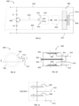
- FIG. 8 illustrates this schematically.
- a portion of a seismic streamer section or ocean bottom cable section 800 is shown in see-though profile view.
- a hydrophone 802 is disposed inside an interior volume of the streamer or cable.
- the interior volume is defined by an enclosure, which in the illustrated case is a streamer jacket 804.
- Connectors, such as the illustrated connector 806, are disposed at one or both ends of the streamer or cable. When present, each connector is typically coupled to a corresponding connector on the end of another section of the streamer or cable.
- the adjoining section is not shown in FIG. 8 so as not to unduly complicate the drawing.
- Some of the pins in the connector, such as the illustrated pin 808, may be used to carry data signals.
- Other pins in the connector, such as the illustrated pin 810 may be used to carry power or control signals.
- Hydrophone 802 provides an output signal via positive and negative electrodes (indicated in the drawing with “+” and “-” symbols).
- the hydrophone electrodes are shown coupled to respective inputs 812, 814 of a differential amplifier 816 via twisted-pair conductors 818.
- An output of the differential amplifier is coupled to an input of a digital to analog converter 820.
- the output of the digital to analog converter is shown coupled to data pin 808 in the connector.
- one or more conductive paths can be established along the length of the streamer via the conformal layer of seawater that is disposed on the outside of the streamer jacket, as generally indicated by dashed lines 822.
- parasitic capacitances are present between the electrodes of each hydrophone and adjacent portions of the streamer jacket, as indicated schematically in the drawing by capacitors C1 and C2. These parasitic capacitances can couple unwanted signals from conductive paths 822 to the electrodes of the sensor, and thus onto the twisted pair conductors that are connected to the hydrophone electrodes. (It should be noted that, in any of the embodiments described herein, more than one twisted pair of conductors may be used, if desired.
- a twisted quad set of conductors comprising two twisted pairs may be used in any of the places where a single twisted pair is shown in the illustrations.
- the unwanted signals are added to the desired signals that are generated by the hydrophones.
- the unwanted signals are therefore coupled to the differential amplifier inputs, along with the desired hydrophone signals, via the one or more twisted pairs of conductors.
- the inventor hereof has discovered that, when the parasitic capacitive coupling between the respective electrodes of a hydrophone and the adjacent portions of a streamer jacket is unbalanced (i.e., when C1 and C2 are not equal), then cross feed signals from conductive paths 822 will appear on the output of the differential amplifier in such systems. This occurs because unequal capacitive coupling of the unwanted signals to the two hydrophone electrodes causes the unwanted signals to be coupled to the electrodes with different amplitudes.
- the unwanted signals are coupled to the electrodes with differing amplitudes, the unwanted signals are not coupled to the differential amplifier inputs in "common mode." When this occurs, the unwanted signals are not rejected by the differential amplifier as desired, but instead are amplified along with the desired hydrophone signals and are presented along with the desired signals at the output of the amplifier.
- FIGS. 9-11 illustrate this problem schematically.
- FIG. 9 is a top view of a conventional marine seismic hydrophone 900 known as a model T2BX, which model is manufactured by Teledyne Technologies Incorporated.
- FIG. 10 is a sectional side view of the T2BX hydrophone taken along the section indicated in FIG. 9 .
- Hydrophone 900 is a generally pill shaped device constructed using two opposed metal shells 902, 904 joined to one another at respective flanges 903, 905.
- the shells are electrically conductive and may be constructed, for example, from a Be/Cu alloy.
- Two piezoelectric elements 906, 908 are adhered to opposite inside-facing surfaces of the shells such that each of them forms a flexural diaphragm.
- a positive output node 910 of the hydrophone is formed by electrically coupling the inward-facing surfaces of the piezoelectric elements together. This is accomplished by passing conductors through respective openings in each of the shells and electrically coupling the conductors together outside of the shell, as shown. In some embodiments, glass beads may be used to insulate the conductors where they pass through openings 914 and to fix the conductors in place.
- a negative output node 912 is formed by soldering a wire to the exterior surface of one of the shells, also as shown.
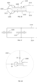
- FIG. 11 presents a schematic diagram of the wiring arrangement shown in FIG. 10 .
- the wiring arrangement of the conventional hydrophone causes the shells 902, 904 to become part of the negative output node along with the negatively polarized faces of the piezoelectric elements.
- the positive output node of the conventional hydrophone comprises only the positively polarized faces of the piezoelectric elements.
- the result of this arrangement is that the surface areas of the two output nodes are unequal. More specifically, because the negative output node includes the shells 902, 904 and the positive output node does not, the conductive surface area of the negative output node is substantially larger than is the conductive surface area of the positive output node.
- an enclosure 1200 is configured to be immersed in a body of water 1201.
- Such an enclosure may comprise, for example, the jacket of a seismic streamer or cable, or the housing of a seismic node.
- a sensor 1202 is disposed within an interior volume 1204 defined by the enclosure.
- the sensor may comprise, for example, a hydrophone (pressure) sensor, or a motion sensor such as a geophone or an accelerometer.
- the sensor comprises a positive output node 1206 and a negative output node 1208.
- the physical characteristics of the output nodes, and the placement of the sensor within the enclosure are designed such that parasitic capacitances between the output nodes and the enclosure are substantially equal to one another.
- a parasitic capacitance between the enclosure and the positive output node of the sensor is substantially equal to a parasitic capacitance between the enclosure and the negative output node of the sensor.
- Both such parasitic capacitances are labeled C3 in the drawing.
- equality of the two parasitic capacitances may be achieved by designing the sensor such that the conductive surface areas of both of its output nodes are substantially equal, or by disposing the sensor within the enclosure so that the distances between the respective sensor output nodes and the adjacent enclosure surfaces result in equal parasitic capacitances, or by a combination of both techniques.
- FIG. 13 illustrates an example system that utilizes the sensor and enclosure arrangement of FIG. 12 .
- the enclosure comprises the outer jacket 1304 of a streamer section 1300.
- a sensor 1202 is disposed within the interior volume of the streamer in a manner consistent with the arrangement of FIG. 12 such that parasitic capacitances C3 between the output nodes of the sensor and the adjacent portions of the streamer jacket are substantially equal, as shown.
- the positive and negative output nodes of the sensor are coupled to first and second signal inputs 1312, 1314 of a differential amplifier.
- the coupling of the output nodes to the differential amplifier inputs may be accomplished using any suitable technique. For example, one or more twisted pairs of conductors 1318 may be used.
- the output of the differential amplifier may be coupled to an analog to digital converter 1320.
- Either the output of the differential amplifier or the output of the digital to analog converter may be sent to a data recording system 112 using a suitable communication system.
- either output may be coupled to the recording system via one or more data telemetry pins 1308 in a connector 1306 disposed at an end of the streamer section.
- unwanted cross feed signals from another connector pin such as from a power or control pin 1310 of the connector, will be coupled with substantially equal amplitudes to each of the positive and negative output nodes of the sensor via the substantially equal parasitic capacitances C3.
- the cross feed signals will appear as common mode signals at the inputs of the differential amplifier, and will be rejected (canceled) by the differential amplifier as desired.
- the amplified signal appearing at the output of the amplifier will represent the sensor output with dramatically reduced or eliminated cross feed noise.
- sensor 1202 may take a variety of forms, provided that the physical characteristics of the sensor output nodes and the position of the sensor within the streamer or other enclosure are such that the parasitic capacitances between the sensor output nodes and the enclosure are substantially balanced.
- Three example sensor types will now be described that may have particular usefulness in such applications.
- FIG. 14 illustrates a pill type sensor 1400 having a body 1401 constructed with opposing electrically conductive shells 1402, 1404.
- the shells may be constructed using any suitable electrically conductive material, including for example the Be/Cu alloy used to construct the T2BX sensor described above.
- the shells may be joined by forming an electrically conductive bond between them, such as by soldering flanges 1403, 1405 together.
- Two generally planar sensing elements 1406, 1408 are disposed on interior surfaces of the respective shells, as shown. Each sensing element is polarized such that it comprises a positive and a negative side.
- the sensing elements may comprise any suitable polarized flexural material. For example, they may be constructed using piezoelectric elements.
- the polarities of the sensing elements face in a same direction, such that the positive side of sensing element 1408 is in contact with the interior surface of shell 1404, whereas the negative side of sensing element 1406 is in contact with the interior surface of shell 1402.
- a positive output node 1410 of the sensor is formed by coupling a wire from the positive side of sensing element 1406 to the exterior of the sensor body.
- a negative output node 1412 of the sensor is formed by coupling a wire from the negative side of sensing element 1408 to the exterior of the sensor body.
- the two output nodes may be made accessible outside the sensor body by any suitable means, including by passing the conductors through respective openings 1414 in the shells. Each opening may be sealed, if desired, with an insulative material such as a glass bead.
- FIG. 15 presents a schematic diagram of the wiring arrangement shown in FIG. 14 .
- the sensing elements of sensor 1400 are wired in series with one another, such that the electrically conductive body 1401 of the sensor is electrically at an equipotential position between the two sensing elements. Because the shells and the sensing elements are symmetrical, this arrangement causes the electrically conductive surface area of positive output node 1410 (which surface area comprises the positive side of sensing element 1406 and the connected positive output node wire) to be substantially equal to the electrically conductive surface area of negative output node 1412 (which surface area comprises the negative side of sensing element 1408 and the connected negative output node wire).
- FIG. 16 illustrates a sensor 1600 that comprises an electrically conductive hollow cylinder 1602.
- the cylinder may be wider in its diameter dimension than it is tall in its height dimension, such that the cylinder exhibits a disk shape.
- the illustrated cylinder includes first and second ends 1604, 1606, each of which defines a surface whose normal faces outwardly from the cylinder in a direction parallel to a longitudinal axis of the cylinder.
- First and second generally planar sensing elements 1608, 1610 are disposed at the ends of the cylinder in contact with respective ones of the outward-facing surfaces.
- the cylinder may comprise an electrically conductive hollow structure with closed ends, or may comprise an electrically conductive ring with open ends.
- the outward-facing surfaces of the cylinder may comprise electrically conductive circular substrates to which the respective generally planar sensing elements may be attached.
- the cylinder and sending elements may be constructed using any suitable materials.
- the cylinder may be constructed using metal, and the sensing elements may be constructed using flexural piezoelectric elements, such as piezoelectric ceramic/metal unimorph bender disks, as shown.
- a unimorph device comprises a piezoelectric element on one side of a flexural disk
- a bimorph device comprises two piezoelectric elements disposed one on each side of a flexural disk.
- the two sensing elements are polarized such that each comprises a positive side and a negative side. In the illustrated embodiment, the same polarity side of each sensing element faces inwardly, in contact with the cylinder.
- the outward-facing surfaces of each sensing element are electrically coupled to one another, such as with a wire 1612.
- One of the sensor output nodes, node 1614, is electrically coupled to the cylinder, while the other sensor output node, node 1616, is electrically coupled to an outward facing surface of one of the sensing elements.
- FIG. 17 presents a schematic diagram of the wiring arrangement of sensor 1600.
- the two sensing elements 1608, 1610 are wired in parallel with one another.
- the electrically conductive surface area of the positive output node comprises the two outwardly facing sides of the sensing elements and the conductors that connect them to the positive sensor terminal, while the electrically conductive surface area of the negative output node comprises the cylinder side surface and the exposed portions of the outward-facing cylinder ends.
- the electrically conductive surface areas of the positive and negative output nodes may be substantially equal, but in some cases may not be.
- the sensor 1600 may be positioned within an interior volume of an enclosure 1800 such that the parasitic capacitances formed between the two sensor output nodes and the enclosure are substantially equal, as indicated in the drawing by the two equal-value capacitances C4.
- the specifics of such placement within the enclosure may vary depending on the shape of the enclosure and the relative sizes of the sensor components.
- the sensor may not be disposed at a center of symmetry of the enclosure in order to achieve balance in the parasitic capacitances. In other embodiments, the opposite may be the case.
- surface areas of piezoelectric sensing elements 1608, 1610, and surface areas of cylinder 1602 may be scaled relative to one another to ensure that the just-described parasitic capacitances will be substantially equal to one another when the sensor 1600 is disposed within the enclosure 1800. This may be accomplished, for example, by choosing a location for mounting the sensor within the enclosure and using a finite element analysis tool to compute the integral (e.g., the sum) of multiple elemental parasitic capacitances computed in all directions around the surfaces of the respective components of the sensor, each to a corresponding point on the surface of the enclosure. Depending on the type of enclosure in which the sensor is to be deployed, the properties of the materials inside the enclosure may also be considered during this computation. For example, for an enclosure comprising a seismic streamer, the presence and location of metal strength members inside the enclosure and of plastic spacers inside the enclosure may be considered when computing the parasitic capacitances.
- FIGS. 19-21 illustrate another type of sensor 2100 that may be constructed using a rigid, electrically insulative rigid ring 2000.
- two polarized generally planar sensing elements 1900 may be adhered to the ring at each of its ends, as shown in the sectional view of FIG. 21 .
- the sensing elements may take a variety of forms.
- the sensing elements may comprise unimorph or bimorph bender disks of the same or a similar type as those discussed above.
- each may comprise a ceramic/metal unimorph bender disk, as shown.
- Each such disk may comprise a single silver-surfaced polarized piezoceramic disk 1902 that is itself adhered to a larger diameter substrate disk 1904.
- the two sensing elements are polarized and are wired in parallel with one another such that the equivalent electrical circuit is the same as that shown in FIG. 17 (the positive sides of each sensing element are electrically coupled to the positive output node of the sensor, and the negative sides of each sensing element are electrically coupled to the negative output node of the sensor).
- the polarities of the sensing elements in sensor 2100 are reversed, however, relative to those shown in FIG. 16 . That is, while each sensing element in sensor 2100 physically faces in an opposite direction from the other sensing element (both face outward relative to the sensor), one sensing element has its negative side facing inward relative to the sensor, and the other sensing element has its positive side facing inward relative to the sensor.
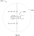
- FIG. 22 illustrates that, when sensor 2100 is disposed within the interior volume of a seismic streamer or cable 2202 having a circular cross section, four parasitic capacitances C5, C6, C7, C8 are formed between the sensor electrodes and the adjacent portions of the enclosure. In general, due to the physical characteristics of the sensing elements and their substrates, C5 # C6 and C7 # C8. Because of the design of sensor 2100, however, the sensor exhibits a center of symmetry 2102. The center of symmetry represents a point about which the sensor is symmetrical in each of three orthogonal axes x, y, z, (the x axis extends into the page).
- C5 C7
- C6 C8
- C5 + C8 C6 + C7
- the sum C5 + C8 represents the effective parasitic capacitance between the streamer jacket or enclosure and the positive electrode of the sensor.
- the sum C6 + C7 represents the effective parasitic capacitance between the streamer jacket or enclosure and the negative electrode of the sensor.
- the same sensor may be mounted with similar effect in enclosures other than streamers or cables.
- the enclosure of a seismic node exhibits symmetry in three orthogonal axes such that the node itself defines a center of symmetry
- the sensor may be placed within the node such that the sensor's center of symmetry is collocated with the node's center of symmetry. With such a placement of the sensor within the node, the parasitic capacitances formed between the node enclosure and the sensor electrodes will be equal.
- the longitudinal axis of the streamer or cable may represent a longitudinal center of symmetry for the streamer or cable, and the sensor may be located at any point along the longitudinal axis.
- the senor may be positioned within the enclosure such that its positive and negative output nodes are substantially equidistant from the enclosure.
- FIG. 24 illustrates a method 2400 of manufacturing any of the sensor devices and systems described herein.
- a sensor element is provided such that the sensor element comprises a positive output node and a negative output node.
- the sensor element can be, for example, a sensor in accordance with any of the sensor embodiments described above.
- an enclosure suitable for submersion in a body of water is provided. Such an enclosure may comprise, for example, a seismic streamer or cable, or a seismic node.
- the sensor element is disposed within the enclosure in a manner such that a parasitic capacitance between the positive output node of the sensor element and the enclosure is substantially equal to a parasitic capacitance between the negative output node of the sensor element and the enclosure.
- Step 2406 may be accomplished in accordance with any of the examples described above, in addition to others.
- the output nodes of the sensor element are electrically coupled to respective inputs of a differential amplifier, which may be contained within the enclosure or which may be located elsewhere.
- the electrical coupling of the output nodes to the differential amplifier may be accomplished using any suitable technique, including with the use of one or more twisted pairs of conductors.
- the method may further comprise scaling surface areas of the sensing elements and of the cylinder such that the above-described parasitic capacitances are substantially equal when the sensor element is disposed within the enclosure.
- a finite element analysis tool may be used for this purpose, if desired.
- FIG. 25 illustrates a method 2500 of manufacturing a geophysical data product using sensors or sensor systems of the types described herein.
- an enclosure is immersed in a body of water.
- a sensor in disposed within the enclosure such that a parasitic capacitance between a positive output node of the sensor and the enclosure is substantially equal to a parasitic capacitance between a negative output node of the sensor and the enclosure.
- the sensor and the enclosure may take a variety of forms, including any of those described above.
- the enclosure may comprise a seismic streamer, cable, or node, and the sensor may comprise any of the example embodiments described above.
- an individual sensor may be used in embodiments, or a group of such sensors may be used, as appropriate to the application.
- the output nodes of the sensor or sensors may be coupled to the inputs of one or more differential amplifiers, and the outputs of the differential amplifiers may be transmitted to a data recording system--either in analog or in digital form.
- one or more seismic sources are activated in the body of water to produce seismic energy that propagates into a subsurface and that is reflected from one or more subsurface geological features.
- signals generated by the sensor or sensors responsive to the reflected seismic energy are recorded in a tangible, computer readable medium, thereby completing the manufacture of a geophysical data product that comprises the computer readable medium with the data contained therein.
- the signals recorded therein may comprise direct outputs of the one or more sensors, or may comprise outputs of one or more differential amplifiers coupled to the sensors, or may comprise outputs of one or more digital to analog converters coupled to respective differential amplifiers, as appropriate to the application.
- FIG. 26 is a block diagram illustrating an example computer system 2600 that may be used to perform any of the methods described above.
- a computer system such as computer system 2600 may also be used to produce a computer-readable survey plan that, if followed by navigation and control equipment onboard a survey vessel, causes the vessel to perform any of the methods described above.
- Computer system 2600 includes one or more central processor unit (“CPU") cores 2602 coupled to a system memory 2604 by a high-speed memory controller 2606 and an associated high-speed memory bus 2607.
- System memory 2604 typically comprises a large array of random-access memory locations, often housed in multiple dynamic random-access memory (“DRAM”) devices, which in turn are housed in one or more dual inline memory module (“DIMM”) packages.
- Each CPU core 2602 is associated with one or more levels of high-speed cache memory 2608, as shown.
- Each core 2602 can execute computer-readable instructions 2610 stored in system memory 2604, and can thereby perform operations on data 2612, also stored in system memory 2604.
- Memory controller 2606 is coupled, via input/output bus 2613, to one or more input/output controllers such as input/output controller 2614.
- Input /output controller 2614 is in turn coupled to one or more tangible, non-volatile, computer readable media such as computer-readable medium 2616 and computer-readable medium 2618.
- Non-limiting examples of such computer-readable media include so-called solid-state disks ("SSDs"), spinning-media magnetic disks, optical disks, flash drives, magnetic tape, and the like.
- SSDs solid-state disks
- Media 2616, 2618 may be permanently attached to computer system 2600 or may be removable and portable. In the example shown, medium 2616 has instructions 2617 (software) stored therein, while medium 2618 has data 2619 stored therein.
- Operating system software executing on computer system 2600 may be employed to enable a variety of functions, including transfer of instructions 2610, 2617 and data 2612, 2619 back and forth between media 2616, 2618 and system memory 2604.
- Computer system 2600 may represent a single, stand-alone computer workstation that is coupled to input/output devices such as a keyboard, pointing device and display. It may also represent one node in a larger, multi-node or multi-computer system such as a cluster, in which case access to its computing capabilities may be provided by software that interacts with and/or controls the cluster. Nodes in such a cluster may be collocated in a single data center or may be distributed across multiple locations or data centers in distinct geographic regions. Further still, computer system 2600 may represent an access point from which such a cluster or multi-computer system may be accessed and/or controlled. Any of these or their components or variants may be referred to herein as "computing apparatus" or a "computing device.”
- data 2619 may correspond to sensor measurements or other data recorded during a marine geophysical survey or may correspond to a survey plan for implementing any of the methods described herein.
- Instructions 2617 may correspond to algorithms for performing any of the methods described herein, or for producing a computer-readable survey plan for implementing one or more of such methods.
- instructions 2617 when executed by one or more computing devices such as one or more of CPU cores 2602, cause the computing device to perform operations described herein on the data, producing results that may be stored in one or more tangible, non-volatile, computer-readable media such as medium 2618.
- medium 2618 constitutes a geophysical data product that is manufactured by using the computing device to perform methods described herein and by storing the results in the medium.
- Geophysical data product 2618 may be stored locally or may be transported to other locations where further processing and analysis of its contents may be performed. If desired, a computer system such as computer system 2600 may be employed to transmit the geophysical data product electronically to other locations via a network interface 2620 and a network 2622 (e.g. the Internet). Upon receipt of the transmission, another geophysical data product may be manufactured at the receiving location by storing contents of the transmission, or processed versions thereof, in another tangible, non-volatile, computer readable medium.
- geophysical data product 2618 may be manufactured by using a local computer system 2600 to access one or more remotely-located computing devices in order to execute instructions 2617 remotely, and then to store results from the computations on a medium 2618 that is attached either to the local computer or to one of the remote computers.
- the word "medium” as used herein should be construed to include one or more of such media.
Landscapes
- Physics & Mathematics (AREA)
- Life Sciences & Earth Sciences (AREA)
- Engineering & Computer Science (AREA)
- Remote Sensing (AREA)
- General Physics & Mathematics (AREA)
- Acoustics & Sound (AREA)
- Environmental & Geological Engineering (AREA)
- Geology (AREA)
- General Life Sciences & Earth Sciences (AREA)
- Geophysics (AREA)
- Geophysics And Detection Of Objects (AREA)
Applications Claiming Priority (3)
| Application Number | Priority Date | Filing Date | Title |
|---|---|---|---|
| US202263356095P | 2022-06-28 | 2022-06-28 | |
| US18/196,789 US20230417938A1 (en) | 2022-06-28 | 2023-05-12 | Low Cross Feed Marine Sensors |
| EP23177792.1A EP4300054A1 (de) | 2022-06-28 | 2023-06-06 | Marine sensoren mit geringer querspeisung |
Related Parent Applications (1)
| Application Number | Title | Priority Date | Filing Date |
|---|---|---|---|
| EP23177792.1A Division EP4300054A1 (de) | 2022-06-28 | 2023-06-06 | Marine sensoren mit geringer querspeisung |
Publications (2)
| Publication Number | Publication Date |
|---|---|
| EP4485012A2 true EP4485012A2 (de) | 2025-01-01 |
| EP4485012A3 EP4485012A3 (de) | 2025-03-26 |
Family
ID=86732053
Family Applications (2)
| Application Number | Title | Priority Date | Filing Date |
|---|---|---|---|
| EP23177792.1A Pending EP4300054A1 (de) | 2022-06-28 | 2023-06-06 | Marine sensoren mit geringer querspeisung |
| EP24213081.3A Pending EP4485012A3 (de) | 2022-06-28 | 2023-06-06 | Marine sensoren mit geringer querspeisung |
Family Applications Before (1)
| Application Number | Title | Priority Date | Filing Date |
|---|---|---|---|
| EP23177792.1A Pending EP4300054A1 (de) | 2022-06-28 | 2023-06-06 | Marine sensoren mit geringer querspeisung |
Country Status (3)
| Country | Link |
|---|---|
| US (1) | US20230417938A1 (de) |
| EP (2) | EP4300054A1 (de) |
| CA (1) | CA3203032A1 (de) |
Families Citing this family (2)
| Publication number | Priority date | Publication date | Assignee | Title |
|---|---|---|---|---|
| WO2019234222A1 (en) | 2018-06-08 | 2019-12-12 | Pgs Geophysical As | Linear array of piezoelectric transducers for towed marine streamers |
| US20250267399A1 (en) * | 2024-02-16 | 2025-08-21 | Pgs Geophysical As | Low Cross Feed Hydrophone and Method of Manufacture |
Family Cites Families (7)
| Publication number | Priority date | Publication date | Assignee | Title |
|---|---|---|---|---|
| US3970878A (en) * | 1975-03-31 | 1976-07-20 | Teledyne Exploration Company | Piezoelectric transducer unit and hydrophone assembly |
| US4017824A (en) * | 1975-06-06 | 1977-04-12 | The Bendix Corporation | Acceleration-insensitive hydrophone |
| US6029113A (en) * | 1998-12-21 | 2000-02-22 | The United States Of America As Represented By The Secretary Of The Navy | Differential hydrophone assembly |
| US6160763A (en) * | 1998-12-28 | 2000-12-12 | Sealandaire Technologies, Inc. | Towed array hydrophone |
| AU2015289607B2 (en) * | 2014-07-17 | 2020-09-03 | Conocophillips Company | Marine seismic surveying including direct far field measurements |
| CN108007980A (zh) * | 2017-11-28 | 2018-05-08 | 北京航天试验技术研究所 | 一种润滑油品质检测电容传感探头 |
| WO2019234222A1 (en) * | 2018-06-08 | 2019-12-12 | Pgs Geophysical As | Linear array of piezoelectric transducers for towed marine streamers |
-
2023
- 2023-05-12 US US18/196,789 patent/US20230417938A1/en active Pending
- 2023-06-06 EP EP23177792.1A patent/EP4300054A1/de active Pending
- 2023-06-06 EP EP24213081.3A patent/EP4485012A3/de active Pending
- 2023-06-13 CA CA3203032A patent/CA3203032A1/en active Pending
Also Published As
| Publication number | Publication date |
|---|---|
| US20230417938A1 (en) | 2023-12-28 |
| CA3203032A1 (en) | 2023-12-28 |
| EP4485012A3 (de) | 2025-03-26 |
| EP4300054A1 (de) | 2024-01-03 |
Similar Documents
| Publication | Publication Date | Title |
|---|---|---|
| US11385367B2 (en) | Dual axis geophones for pressure/velocity sensing streamers forming a triple component streamer | |
| US4821241A (en) | Noise-cancelling streamer cable | |
| US7239577B2 (en) | Apparatus and methods for multicomponent marine geophysical data gathering | |
| US9057800B2 (en) | Marine seismic acquisition system | |
| EP4485012A2 (de) | Marine sensoren mit geringer querspeisung | |
| US20060193203A1 (en) | Apparatus for attenuating noise in marine seismic streamers | |
| US4984218A (en) | Marine acoustic array configured for tow noise reduction | |
| US6853604B2 (en) | Solid marine seismic cable | |
| US11079506B2 (en) | Multicomponent streamer | |
| US20100039889A1 (en) | Mounting a seismic sensor in a cable | |
| US9097817B2 (en) | Seismic sensor cable | |
| US20260029551A1 (en) | Seismic Data Acquisition with Extended Dynamic Range | |
| US12130396B2 (en) | Neutrally buoyant particle velocity sensor | |
| US4725990A (en) | Marine shear cable | |
| US20100103771A1 (en) | Providing a survey carrier structure having equidistant survey sensors | |
| US11889760B2 (en) | Seismic pressure and acceleration sensor | |
| US12099155B2 (en) | Attenuation of axial vibration noise in pressure sensor measurements | |
| US20250267399A1 (en) | Low Cross Feed Hydrophone and Method of Manufacture | |
| AU2014201151B2 (en) | Streamer design for geophysical prospecting | |
| US20250130342A1 (en) | Marine Seismic Survey Designs for Shallow Subsurface Investigations | |
| BR112023006948B1 (pt) | Sistemas de sensores sismícos | |
| GB2579411A (en) | Seismic acquisition system comprising short streamers |
Legal Events
| Date | Code | Title | Description |
|---|---|---|---|
| PUAI | Public reference made under article 153(3) epc to a published international application that has entered the european phase |
Free format text: ORIGINAL CODE: 0009012 |
|
| STAA | Information on the status of an ep patent application or granted ep patent |
Free format text: STATUS: THE APPLICATION HAS BEEN PUBLISHED |
|
| AC | Divisional application: reference to earlier application |
Ref document number: 4300054 Country of ref document: EP Kind code of ref document: P |
|
| AK | Designated contracting states |
Kind code of ref document: A2 Designated state(s): AL AT BE BG CH CY CZ DE DK EE ES FI FR GB GR HR HU IE IS IT LI LT LU LV MC ME MK MT NL NO PL PT RO RS SE SI SK SM TR |
|
| REG | Reference to a national code |
Ref country code: DE Ref legal event code: R079 Free format text: PREVIOUS MAIN CLASS: G01V0001180000 Ipc: G01H0011080000 |
|
| PUAL | Search report despatched |
Free format text: ORIGINAL CODE: 0009013 |
|
| AK | Designated contracting states |
Kind code of ref document: A3 Designated state(s): AL AT BE BG CH CY CZ DE DK EE ES FI FR GB GR HR HU IE IS IT LI LT LU LV MC ME MK MT NL NO PL PT RO RS SE SI SK SM TR |
|
| RIC1 | Information provided on ipc code assigned before grant |
Ipc: G01V 1/18 20060101ALI20250217BHEP Ipc: G01H 11/08 20060101AFI20250217BHEP |
|
| STAA | Information on the status of an ep patent application or granted ep patent |
Free format text: STATUS: REQUEST FOR EXAMINATION WAS MADE |
|
| 17P | Request for examination filed |
Effective date: 20250924 |
|
| GRAP | Despatch of communication of intention to grant a patent |
Free format text: ORIGINAL CODE: EPIDOSNIGR1 |
|
| STAA | Information on the status of an ep patent application or granted ep patent |
Free format text: STATUS: GRANT OF PATENT IS INTENDED |