EP4484991A1 - A method for operating a liquid helium cooling system of a magnetic resonance imaging system and a magnetic resonance imaging system - Google Patents
A method for operating a liquid helium cooling system of a magnetic resonance imaging system and a magnetic resonance imaging system Download PDFInfo
- Publication number
- EP4484991A1 EP4484991A1 EP23182279.2A EP23182279A EP4484991A1 EP 4484991 A1 EP4484991 A1 EP 4484991A1 EP 23182279 A EP23182279 A EP 23182279A EP 4484991 A1 EP4484991 A1 EP 4484991A1
- Authority
- EP
- European Patent Office
- Prior art keywords
- power
- during
- electrical power
- time
- helium
- Prior art date
- Legal status (The legal status is an assumption and is not a legal conclusion. Google has not performed a legal analysis and makes no representation as to the accuracy of the status listed.)
- Pending
Links
Images

Classifications
-
- G—PHYSICS
- G01—MEASURING; TESTING
- G01R—MEASURING ELECTRIC VARIABLES; MEASURING MAGNETIC VARIABLES
- G01R33/00—Arrangements or instruments for measuring magnetic variables
- G01R33/20—Arrangements or instruments for measuring magnetic variables involving magnetic resonance
- G01R33/28—Details of apparatus provided for in groups G01R33/44 - G01R33/64
- G01R33/38—Systems for generation, homogenisation or stabilisation of the main or gradient magnetic field
- G01R33/3804—Additional hardware for cooling or heating of the magnet assembly, for housing a cooled or heated part of the magnet assembly or for temperature control of the magnet assembly
-
- G—PHYSICS
- G01—MEASURING; TESTING
- G01R—MEASURING ELECTRIC VARIABLES; MEASURING MAGNETIC VARIABLES
- G01R33/00—Arrangements or instruments for measuring magnetic variables
- G01R33/20—Arrangements or instruments for measuring magnetic variables involving magnetic resonance
- G01R33/44—Arrangements or instruments for measuring magnetic variables involving magnetic resonance using nuclear magnetic resonance [NMR]
- G01R33/48—NMR imaging systems
-
- A—HUMAN NECESSITIES
- A61—MEDICAL OR VETERINARY SCIENCE; HYGIENE
- A61B—DIAGNOSIS; SURGERY; IDENTIFICATION
- A61B5/00—Measuring for diagnostic purposes; Identification of persons
- A61B5/05—Detecting, measuring or recording for diagnosis by means of electric currents or magnetic fields; Measuring using microwaves or radio waves
- A61B5/055—Detecting, measuring or recording for diagnosis by means of electric currents or magnetic fields; Measuring using microwaves or radio waves involving electronic [EMR] or nuclear [NMR] magnetic resonance, e.g. magnetic resonance imaging
-
- G—PHYSICS
- G01—MEASURING; TESTING
- G01R—MEASURING ELECTRIC VARIABLES; MEASURING MAGNETIC VARIABLES
- G01R33/00—Arrangements or instruments for measuring magnetic variables
- G01R33/20—Arrangements or instruments for measuring magnetic variables involving magnetic resonance
- G01R33/28—Details of apparatus provided for in groups G01R33/44 - G01R33/64
-
- G—PHYSICS
- G01—MEASURING; TESTING
- G01R—MEASURING ELECTRIC VARIABLES; MEASURING MAGNETIC VARIABLES
- G01R33/00—Arrangements or instruments for measuring magnetic variables
- G01R33/20—Arrangements or instruments for measuring magnetic variables involving magnetic resonance
- G01R33/28—Details of apparatus provided for in groups G01R33/44 - G01R33/64
- G01R33/32—Excitation or detection systems, e.g. using radio frequency signals
- G01R33/34—Constructional details, e.g. resonators, specially adapted to MR
- G01R33/34015—Temperature-controlled RF coils
- G01R33/34023—Superconducting RF coils
-
- G—PHYSICS
- G01—MEASURING; TESTING
- G01R—MEASURING ELECTRIC VARIABLES; MEASURING MAGNETIC VARIABLES
- G01R33/00—Arrangements or instruments for measuring magnetic variables
- G01R33/20—Arrangements or instruments for measuring magnetic variables involving magnetic resonance
- G01R33/28—Details of apparatus provided for in groups G01R33/44 - G01R33/64
- G01R33/32—Excitation or detection systems, e.g. using radio frequency signals
- G01R33/34—Constructional details, e.g. resonators, specially adapted to MR
- G01R33/34015—Temperature-controlled RF coils
- G01R33/3403—Means for cooling of the RF coils, e.g. a refrigerator or a cooling vessel specially adapted for housing an RF coil
-
- G—PHYSICS
- G01—MEASURING; TESTING
- G01R—MEASURING ELECTRIC VARIABLES; MEASURING MAGNETIC VARIABLES
- G01R33/00—Arrangements or instruments for measuring magnetic variables
- G01R33/20—Arrangements or instruments for measuring magnetic variables involving magnetic resonance
- G01R33/28—Details of apparatus provided for in groups G01R33/44 - G01R33/64
- G01R33/32—Excitation or detection systems, e.g. using radio frequency signals
- G01R33/36—Electrical details, e.g. matching or coupling of the coil to the receiver
-
- G—PHYSICS
- G01—MEASURING; TESTING
- G01R—MEASURING ELECTRIC VARIABLES; MEASURING MAGNETIC VARIABLES
- G01R33/00—Arrangements or instruments for measuring magnetic variables
- G01R33/20—Arrangements or instruments for measuring magnetic variables involving magnetic resonance
- G01R33/28—Details of apparatus provided for in groups G01R33/44 - G01R33/64
- G01R33/38—Systems for generation, homogenisation or stabilisation of the main or gradient magnetic field
- G01R33/3806—Open magnet assemblies for improved access to the sample, e.g. C-type or U-type magnets
Definitions
- the invention relates to a method for operating a liquid helium cooling system of a magnetic resonance imaging system and a corresponding computer program and magnetic resonance imaging system.
- Magnetic resonance imaging (MRI) scanners have a high energy consumption.
- an energy consumption of a typical MRI scanner can be in the order of magnitude of about 70 MWh per year.
- One important factor is the energy needed for cooling the MRI scanner, in particular the magnet and coil of the scanner.
- the magnetic fields typically being in a range of up to 3 Tesla and even higher in some cases, superconductivity is need, which in turn requires correspondingly low temperatures.
- liquid helium cooling is applied, the temperature of liquid helium being at about 4 Kelvin. Due to the absorption of heat, the liquid helium will evaporate over time going into the gaseous phase.
- MRI scanners usually comprise a helium liquifying means such as a cold head.
- the liquifying means recondenses the helium that has evaporated back to the liquid state.
- a method for operating a liquid helium cooling system of a magnetic resonance imaging system comprising a helium liquifying means, such as a cold head, is provided.
- the liquifying means has a standard operating mode that is adapted to allow performing a magnetic resonance scan without venting of substantial amounts of helium. The method comprises the following steps:
- both, off-times and an electrical power availability are considered when determining the at least one time slot in which the power-saving mode is activated.
- the method may be used to adapt the power usage not only according to the first timetable of scan times but also according to the availability of electrical power.
- two timetables may be used, the first timetable and the second timetable.
- a timetable may be understood such that times during which the MRI system is to be used and different availabilities of electric power are related to times, e.g. over the course of a day or, preferably, over the course of more than one day.
- the time slots of the second timetable may be very small, optionally infinitely small.
- Very small time slots may be used to represent a basically continuous change of electrical power availability.
- the power-saving mode may be activated during several time slots.
- at least some of the time slots may represent longer periods of time, such as one or several hours.
- Time slots representing larger amounts of time may, for example, be useful when the electrical power availability is constant or nearly constant over these longer periods of time, such as in the case of electric power price being set differently at different parts of the day or the solar cells producing relatively constant amounts of electric power during a particular period of time.
- the availability of electrical power may, for example, differ over the course of a day, of a week, or of a year.
- the electrical power availability may be connected to a price of electrical power, such as the price being different at certain times at night or in the evening than at other times of the day.
- the electrical power availability may also be connected to the production of electrical power, such as solar cells producing more electrical power during periods of sunshine, or wind-mills being dependent on the intensity of wind.
- This method makes it possible to significantly reduce the energy consumption during the time, in which the power-saving mode is active. Accordingly, the method may advantageously be used to adapt to the problem of renewable energies not being available to the same degree at any time.
- the power-saving mode may be active during a time at night when there is no sunshine and the standard operating mode may be activated after or at sunrise and before examinations with the MRI system are performed.
- the system depends on renewable energies, due to this method, it may be feasible to reduce the number of batteries or other energy storage devices needed for operation during the night.
- the operation of the MRI system for examinations may start about two to three hours after sunrise.
- the overall energy consumption may be reduced with the method according to the invention due to the power-saving mode requiring less energy.
- the predefined time is defined such that the system is operable during the next scan time without the risk of venting a substantial amount of helium during or before the next MRI scan.
- the time in which the system operates in the standard operating mode may be seen as a recovery period, in which the magnet of the MRI system is cooled down to operating temperature and/or is prepared to be ready to be operable again.
- the activation of the standard operating mode and the activation of the power-saving mode are timed such that the standard operating mode is running during a time slot associated with a higher level of electrical power availability than the time slot in which the power-saving mode is activated, preferably such that the standard operating mode is running during a time slot associated with the level of highest electrical power availability.
- the level of electrical power availability is taken into account during step (c) of the method, i.e. when determining at least one time slot within the off-times that is not associated with the level of highest electrical power availability.
- the at least one time slot may be determined such that the activating of the standard operating mode takes place during a time slot of a higher electrical power availability, preferably the highest electrical power availability.
- the electrical power availability when the standard operating mode is activated at the predefined time may thus be taken into account. This may allow a more efficient use of energy, since this embodiment may ensure that enough and/or relatively inexpensive power is available for the standard operating mode.
- the predefined time before the beginning of the scan time may be adjusted depending on the next scheduled scan, in particular depending on an expected heat generation of the next scheduled scan. For example, the predefined time may be shortened, if less heat generation is expected.
- a liquifying means is usually adapted to re-condense helium gas or helium vapor back to the liquid state.
- some of the helium may be in the gaseous phase after having cooled the MRI magnet.
- a typical liquifying means is a cold head that is known in the state of the art.
- a cold head may also sometimes be called or classified as cryocooler.
- the helium may be contained inside a cryostat.
- the superconductive wire material of the MRI coils may be immersed in a bath of the liquid helium. Accordingly, the power-saving mode may be a mode in which the liquifying means is operated at reduced power or in which the liquifying means is switched off.
- the power-saving mode may advantageously require a lower average amount of electrical power than the standard operating mode.
- the power-saving mode may be regarded as a controlled temporary disabling of the liquifying means or as a controlled operational reduction of the liquifying means.
- the amount of gaseous helium may increase, in particular due to ambient heat.
- the power-saving mode may be configured not to be sufficient to keep (most of) the helium in the liquid phase over a long time, such as for a period of time of more than 5 hours. Hence, for example, the amount of gaseous helium may slowly increase during the power-saving mode.
- the standard operating mode is in particular adapted to allow performing a magnetic resonance scan without venting of substantial amounts of helium. This may be understood such that the cooling power of the liquifying means during the standard operating mode is so strong, that enough gaseous helium can be brought into the liquid phase during a magnetic resonance scan to prevent the need of venting some of the helium.
- an amount of electrical power per time unit provided to the helium liquifying means during the power-saving mode is on average at least three times lower, preferably at least four times lower, than during the standard operating mode.
- the lower electrical power consumption may, for example, be achieved by switching the liquifying means off temporarily or even constantly during the power-saving mode. Alternatively, the lower electrical power consumption may be achieved by providing a constantly reduced amount of electrical power.
- At least one time slot is determined that is not associated with the level of highest electrical power availability and the power-saving mode is activated during this at least one time slot.
- the at least one time slot is chosen such that enough time is left for the standard operating mode to be activated at the latest at the predefined time before the beginning of the next scan time.
- determining the at least one time slot may preferably be performed by already considering the time needed to activate the standard operating mode in step (e). For this purpose, in some situations, it may be advantageous not to choose the time slot with the lowest electrical power availability for the power-saving mode, since, in some situations, there may not be enough time afterwards to activate the standard mode in due time before the operation of the MRI system is scheduled. On the other hand, when it is possible, applying the power-saving mode, in a time slot with the lowest electrical power availability out of all time slots may be particularly advantageous.
- the power-saving mode is a switch-off mode in which the liquifying means is switched off or an interleave mode in which the liquifying means is alternately switched on and off such that the switch-off times are at least three times longer than the switch-on times.
- the power-saving mode being a switch-off mode may advantageously allow to save a greater amount of energy during the power-saving mode. This may, in particular be beneficial if the power-saving mode can only be applied during a relatively short time slot.
- the interleave mode may in particular be advantageous, if a longer time-slot is available.
- the interleave mode may allow to have the power-saving mode active for a longer period of time before a venting of helium would occur or would be needed. Additionally and/or alternatively, the interleave mode may also be particularly advantageous, if the time after activating the standard operating mode and before starting the first scan of the MRI system is rather short. This may for example be the case, when scanning is supposed to start early in the day and a higher availability of electrical power starts only shortly before that, such as due to solar powered energy being available only after sunrise. In this case, the interleave mode may allow to reduce the amount of helium being in the gaseous phase at the time the standard operating mode is activated.
- the recovery time may be shorter when using the interleave mode by the price of a lower energy saving.
- both the switch-off mode and the interleave mode may help to significantly reduce the energy consumption of the cooling system and, thus, of the magnetic resonance imaging system. It has been found that in the interleave mode, the switch-off times being at least three times longer than the switch-on times, may be a good ratio to efficiently save energy while having some advantages of the interleave mode.
- the interleave mode may preferably be configured such that the switch-on times are in the order of magnitude of one or a few minutes, preferably 1 to 20 minutes, more preferably 2 to 8 minutes, and even more preferably 2 to 6 minutes.
- the switch-off times may be in the order of magnitude of three times the switch on times or more, e.g., particularly preferred in the range of 6 to 18 minutes or more. It has been found that these amounts of time can be particularly advantageous to both ensure an efficient amount of energy saving and preventing a venting of helium for a particularly long time.
- the liquifying means is switched off no longer than a predefined amount of time, wherein the predefined amount of time is defined such that a substantial venting of helium is avoided.
- the predefined amount of time may depend on the MRI system and/or its venting configuration.
- the liquifying means may preferably be switched off for at most 4 hours, preferably at most 3 hours.
- the time till a venting occurs was in the time range of between 4 hours and 3 minutes and 5 hours and 21 minutes. The tests have been carried out, by keeping the MRI magnet in a stable configuration and then switching off the cold head.
- the time until the magnet vented was measured. This time was defined to be when the relief valve opens and the magnet starts losing helium gas into the recovery line. Accordingly, based on the tests, a maximum amount of time of 4 hours may be feasible. A maximum amount of at most 3 hours may be more beneficial for providing a safety margin, therefore allowing, for example, for potential technical problems to occur without necessarily directly leading to a venting of helium. It has been found, for a commercially available MRI system, that about 12kWh may be saved during one power-saving mode of 3 hours. This amounts to 4kW per hour being saved by switching of the cold head and a helium compressor. The amount saved may likely vary for different systems.
- the levels of electrical power availability are based on an expected price of electric power during the corresponding time slot and/or on an expected amount of electric power production during the corresponding time slot, the level of lowest electrical power availability being associated with a high expected price and/or a low expected amount of power production.
- the expected amount of electric power production may, for example, depend on the productivity of a renewable energy device, such as solar power cells or a wind turbine.
- the power-saving mode may be activated towards the end of a night, e.g. 2 to 3 hours before sunrise, and the standard operating mode may be activated after sunrise and a sufficient time, e.g. 2 hours, before a planned start of scanning with the MRI system begins.
- the expected price may for example vary based on a user's electric power contract.
- the user may have a contract, in which the energy during the night is cheaper than during the day.
- the power-saving mode may be started towards the end of high-cost hours and the standard operating mode may be activated during low-cost hours.
- the second timetable is updated dynamically based on received electrical power availability data.
- the electrical power availability data may comprise information, in particular predictions and/or estimates, about the availability of renewable energies and/or about energy prices.
- the received electrical power availability data may comprise a weather forecast or data derived from a weather forecast.
- the electrical power availability data may comprise sunshine hours.
- the weather forecast may comprise information about an occurrence of clouds in the sky above solar panels.
- the weather forecast may comprise a prediction of a wind speed at the location of a wind turbine used for providing energy for the MRI system.
- a dynamic updating of the timetable may allow to adjust the timing of the power-saving mode to the actual current situation and/or the estimated situation in the near future.
- the first timetable is updated dynamically based on a scheduling, in particular user-input scheduling, of magnetic resonance scans.
- the timing of the power-saving mode and the standard operating mode may thus be adapted dynamically, in particular by even taking into account changes on short notice.
- the first timetable may be updated in the evening or at night based on the scheduling for the next day, and the power-saving mode and the standard operating mode for this night may be set according to the updated first timetable.
- the power-saving mode may be shortened compared to other nights.
- the time during which the standard operating mode has to be activated before scanning can start may also be shorter due to the shorter time the power-saving mode was activated and hence the smaller amount of gaseous helium.
- the predefined time before the beginning of the next scan time is between 0.5 and 5 hours, preferably between 1 and 4 hours, more preferably between 1.5 and 3 hours.
- a predefined time being in the range of 0.5 to 5 hours may be enough to make the system operable again.
- the time that is needed typically depends on the specific system, in particular the cooling system and the generation of heat during a scan.
- the predefined time may vary depending on the system.
- a predefined time in the range between 1 and 4 hours may be applicable for many typical systems. It has been found that a predefined time between 1.5 and 3 hours may be particularly advantageous at least for some commercially available systems, in particular 1.5 Tesla systems.
- a partial power-saving mode is active during off-times that are neither operated in the power-saving mode nor in the standard operating mode, wherein, in the partial power-saving mode, the liquifying means is supplied with a lower average amount of electrical power than during the standard operating mode and with a higher average amount of electrical power than during the power-saving mode.
- the power-saving mode may allow to further save energy.
- the partial power-saving mode may be used always when no scan is scheduled and outside the timeslots the power-saving mode or the standard operating mode following the power-saving mode until the cooling system is recovered is activated.
- the partial power-saving mode can be a useful addition to the power-saving mode, for example in cases when there is no suitable time slot for the standard operating mode to recover the cooling system before the next scan.
- the partial power-saving mode is preferably configured such that the helium will not vent as long as the scanner is not operated.
- the partial power-saving mode may comprise switch-off times and switch-on times.
- the power-saving mode may be configured corresponding to the interleave mode described herein with respect to the power-saving mode.
- the liquifying means may alternately be switched on and off such that the switch-off times are less than three times longer than the switch-on times.
- the liquifying means is alternately switched on and off such that the switch-off times are at least as long as and at most 2.5 times longer than the switch-on times. It has been found that a partial power-saving mode with these relative times can, on the one hand, provide an effective way of saving power and, on the other hand, ensure that under normal conditions no substantial amount of helium is vented.
- the switch-off times can be in the range of 5 to 12 minutes, preferably 6 to 10 minutes.
- the partial power-saving mode comprises switch-off times are at least 1.5 times and at most 2.5 as long as the switch-on times.
- the switch-off times may be twice as long as the switch-on times, such as the switch-off times being 8 minutes and the switch-on times being 4 minutes.
- the partial-saving mode may, for example, comprise operating the liquifying means at an essentially constant reduced power consumption.
- a computer program comprises instructions which, when the program is executed by a control unit of a magnetic resonance imaging system or of a liquid helium cooling system of a magnetic resonance imaging system cause the control unit to carry out the steps of the method as described herein. All features and advantages of the method may be adapted to the computer program and vice versa.
- a magnetic resonance imaging system comprising a helium liquifying means such as a cold head
- the liquifying means is configured to have a standard operating mode in which the liquifying means is supplied with an amount of electrical power that allows performing a magnetic resonance scan without venting a substantial amount of helium and a power-saving mode in which the liquifying means is supplied with a lower average amount of electrical power than during the standard operating mode.
- the system is configured to activate the power-saving mode during a time slot, in which there is no scheduled scan and in which an availability of electrical power is reduced, and activate the standard operating mode at the latest at a predefined time before the beginning of the next scheduled scan such that the system is operable during the next scan without the risk of venting a substantial amount of helium during or before the next scan time.
- the system may in particular be configured to carry out the method as described herein. All features and advantages of the method and of the computer program may be adapted to the magnetic resonance imaging system and vice versa.
- the system may comprise a control unit that is configured to control the liquifying means and activate the different modes of the liquifying means.
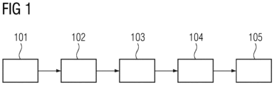
- Figure 1 shows a flow diagram of a method for operating a liquid helium cooling system of a magnetic resonance imaging system 11 according to an embodiment of the invention.
- a first timetable and a second timetable are provided.
- the first timetable comprises scan times of the magnetic resonance imaging system 11.
- the second timetable comprises a plurality of time slots 8 and each time slot 8 is associated with one of at least two different levels of electrical power availability.
- the levels of electrical power availability may be based on an expected price of electric power during the corresponding time slot 8. Additionally or alternatively the levels of electrical power availability may be based on an expected amount of electric power production during the corresponding time slot 8.
- the second timetable may be updated dynamically based on received electrical power availability data.
- a current weather forecast may be used to update the second timetable by considering the weather forecast in order to determine an expected amount of electrical power production, e.g. as produced by wind turbines or solar panels. Updating the second timetable dynamically may provide a second timetable that predicts the actual electrical power availability of power production more accurately.
- step 102 based on the first timetable off-times are determined during which off-times the system is not used for scanning.
- At least one time slot 8, 81 within the off-times is determined that is not associated with the level of highest electrical power availability.
- the at least one time slot 81 is preferably associated with a level of lowest electrical power availability out of all time slots 8 within the off-times.
- the level of lowest electrical power availability may in particular be associated with a high expected price and/or a low expected amount of power production.
- the at least one time slot 8, 81 is further determined such that later, in step 105, the standard operating mode 5 is running during a time slot 8 associated with a higher level of electrical power availability than the time slot 8, 81 in which the power-saving mode 4 is activated in step 104.
- a power-saving mode 4 is activated during the determined at least one time slot 8, 81.
- a liquifying means of the liquid cooling system such as a cold head, is supplied with a lower average amount of electrical power than during a standard operating mode 5.
- the standard operating mode 5 is adapted to allow performing a magnetic resonance scan without venting of substantial amounts of helium.
- an amount of electrical power per time unit provided to the helium liquifying means during the power-saving mode 4 is on average at least three times lower than during the standard operating mode 5.
- the power-saving mode 4 may be a mode in which the liquifying means is operated only in intervals or in which the liquifying means is completely switched off.
- the power-saving mode 4 may be configured not to be sufficient to keep the helium of the cooling system in the liquid phase over a long time. In particular, the amount of gaseous helium may slowly increase during the power-saving mode 4.
- the standard operating mode 5 of the liquifying means is activated. This happens at the latest at a predefined time before the beginning of the next scan time.
- the predefined time is defined such that the system is operable during the next scan time without the risk of venting a substantial amount of helium during or before the next MRI scan.
- the standard operating time is started early enough to enable a recovery of the cooling system and/or of the temperature of the magnet that is to be cooled by the cooling system.
- the predefined time before the beginning of the next scan time is between 1.5 and 3 hours, e.g. 2 hours, before the next scan time.
- the standard operating mode 5 is started such that the standard operating mode 5 is running during a time slot 8 associated with the level of highest electrical power availability.
- the at least one time slot 8, 81 is preferably determined accordingly, to ensure that the power-saving mode 4 ends right when the time slot 8 with the level of highest electrical power availability starts.
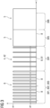
- Figure 2 shows a diagram of the electrical power fed to the liquifying means of a helium cooling system of a magnetic resonance imaging system 11 over time while a method according to an embodiment of the invention is applied.
- the electrical power is either on, e.g. on maximum power setting, or off.
- the liquifying means is operated in a partial power-saving mode 6. This may for example be during the earlier hours of the night.
- the power of the liquifying means is on and off alternatingly.
- the switch-off times are about 1.5 times as long as the switch-on times.
- another ratio may be applied.
- the liquifying may instead be operated in a standard operating mode 5 at least temporarily.
- a first timetable comprising scan times of the magnetic resonance imaging system 11 and a second timetable comprising a plurality of time slots 8 is provided.
- Each time slot 8 is associated with one of at least two different levels of electrical power availability. While the time slots 8 are drawn with about equal spacing in this example, the time slots 8 may also be of different spacing depending on the time development of the electrical power availability.
- a further step 202 comprises determining off-times when the system is not used for scanning based on the first timetable.
- a further step 203 comprises determining at least one time slot 81 within the off-times that is not associated with the level of highest electrical power availability based on the second timetable. This may for example be in the later hours of the night.
- the at least one time slot 81 comprises three time slots 81.
- the power-saving mode 4 is activated by switching off the power of the liquifying means, step 204.
- the power-saving mode 4 is a switch-off mode 41 in which the cooling system is not active.
- the liquifying means is switched off no longer than a predefined amount of time that is defined such that a substantial venting of helium is avoided.
- the liquifying means may be switched off for at most 3 hours. In this example, this corresponds to the three chosen time slots 81.
- the cooling system may consume on average around 4 kW. Accordingly, in this example, 12 kWh can be saved during the power-saving mode 4.
- the standard operating mode 5 is activated, step 205.
- the activation of the standard operating mode 5 and the activation of the power-saving 4 mode are timed such that the standard operating mode 5 is running during a time slot 8 associated with a higher level of electrical power availability than the time slot 81 in which the power-saving mode 4 is activated.
- the helium cooling system recovers until it is ready in step 206 to operate the scanner of the magnetic resonance imaging system 11 without venting helium.
- the standard operating mode 5 is also active.
- Figure 3 shows a diagram of the electrical power fed to the liquifying means of a helium cooling system of a magnetic resonance imaging system 11 over time while a method according to another embodiment of the invention is applied.
- the electrical power is either on, e.g. on maximum power setting, or off.
- the liquifying means is operated in a partial power-saving mode 6.
- the power of the liquifying means is on and off alternatingly.
- the switch-off times are about 2 times as long as the switch-on times.
- another ratio may be applied.
- the first steps 301-303 of the method according to the invention are performed.
- steps 301-303 may, for example, be carried out analogously as described with respect to the embodiment shown in figure 2 .
- one time slot 81 is determined for the power-saving mode 4.
- the power-saving mode 4 is activated, step 304.
- the power-saving mode 4 is an interleave mode 42 in which the liquifying means is alternately switched on and off.
- the switch-off times are about 4.5 times longer than the switch-on times.
- the power-saving mode 4 last no longer than a predefined amount of time that is defined such that a substantial venting of helium is avoided.
- the electrical power availability may be relatively constant in this time slot 81. E.g.
- the time slot 81 may be associated with the lowest electrical power availability, such as during the night when electrical power is obtained from solar panels.
- the standard operating mode 5 is activated, step 305.
- the activation of the standard operating mode 5 and the activation of the power-saving 4 mode are timed such that the standard operating mode 5 is running during a time slot 8 associated with a higher level of electrical power availability than the time slot 81 in which the power-saving mode 4 is activated.
- the helium cooling system recovers until it is ready in step 306 to operate the scanner of the magnetic resonance imaging system 11 without venting helium.
- the standard operating mode 5 is also active.
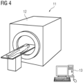
- FIG. 4 shows a magnetic resonance imaging system 11 according to an embodiment of the invention.
- the magnetic resonance imaging system 11 comprises a liquifying means (not shown) that is at least partially inside a gantry 12.
- the liquifying means is configured to have a standard operating mode 5 in which the liquifying means is supplied with an amount of electrical power that allows performing a magnetic resonance scan without venting a substantial amount of helium and a power-saving mode 4 in which the liquifying means is supplied with a lower average amount of electrical power than during the standard operating mode 5.
- the magnetic resonance imaging system 11 comprises a control unit 13 and is configured to, via the control unit 13, activate the power-saving mode 4 during a time slot 8, 81, in which there is no scheduled scan and in which an availability of electrical power is reduced, and activate the standard operating mode 5 at the latest at a predefined time before the beginning of the next scheduled scan such that the system is operable during the next scan without the risk of venting a substantial amount of helium during or before the next scan time.
Landscapes
- Physics & Mathematics (AREA)
- General Physics & Mathematics (AREA)
- Condensed Matter Physics & Semiconductors (AREA)
- Health & Medical Sciences (AREA)
- Life Sciences & Earth Sciences (AREA)
- High Energy & Nuclear Physics (AREA)
- Nuclear Medicine, Radiotherapy & Molecular Imaging (AREA)
- Thermal Sciences (AREA)
- Heart & Thoracic Surgery (AREA)
- General Health & Medical Sciences (AREA)
- Engineering & Computer Science (AREA)
- Medical Informatics (AREA)
- Molecular Biology (AREA)
- Surgery (AREA)
- Animal Behavior & Ethology (AREA)
- Biomedical Technology (AREA)
- Public Health (AREA)
- Veterinary Medicine (AREA)
- Pathology (AREA)
- Biophysics (AREA)
- Radiology & Medical Imaging (AREA)
- Magnetic Resonance Imaging Apparatus (AREA)
Abstract
A method for operating a liquid helium cooling system of a magnetic resonance imaging system (11), comprising the following steps:(a) providing a first timetable comprising scan times and a second timetable comprising a plurality of time slots (8) associated with one of at least two different levels of electrical power availability;(b) determining off-times when the system is not used for scanning based on the first timetable;(c) based on the second timetable, determining at least one time slot (8, 81) within the off-times that is not associated with the level of highest electrical power availability,(d) activating a power-saving mode (4) during the determined at least one time slot (8, 81);(e) activating a standard operating mode (5) of the liquifying means at the latest at a predefined time before the beginning of the next scan time.
Description
- The invention relates to a method for operating a liquid helium cooling system of a magnetic resonance imaging system and a corresponding computer program and magnetic resonance imaging system.
- Independent of the grammatical term usage, individuals with male, female or other gender identities are included within the term.
- Magnetic resonance imaging (MRI) scanners have a high energy consumption. For example, an energy consumption of a typical MRI scanner can be in the order of magnitude of about 70 MWh per year. One important factor is the energy needed for cooling the MRI scanner, in particular the magnet and coil of the scanner. In order to generate the magnetic fields needed for MRI scanning, the magnetic fields typically being in a range of up to 3 Tesla and even higher in some cases, superconductivity is need, which in turn requires correspondingly low temperatures. For this purpose, liquid helium cooling is applied, the temperature of liquid helium being at about 4 Kelvin. Due to the absorption of heat, the liquid helium will evaporate over time going into the gaseous phase. This effect of helium evaporation usually occurs to a significantly larger degree when the MRI scanner is actively used, i.e. during a scan, due to the heat that is created when operating the scanner. However, even when the scanner is not used, the helium will usually evaporate slowly over time. In order to counter this effect of helium evaporation, MRI scanners usually comprise a helium liquifying means such as a cold head. The liquifying means recondenses the helium that has evaporated back to the liquid state. Since Helium requires a considerably larger amount of space when being in the gaseous phase then when being in the liquid phase (for about a factor of 750 under standard conditions), the system will typically have to vent some of the helium, if the amount of gaseous helium becomes too large. This is undesirable, since a resupply of additional helium is rather expensive and may requires additional maintenance breaks of the scanner. Furthermore, if too little Helium is in the liquid phase, the cooling power may no longer be sufficient, potentially leading to damage on the MRI system, for example, due to a quenching of the magnet coil. Hence, it is typically vital to ensure that the helium remains in the liquid phase.
- On the other hand, the energy consumption mentioned above of such a cooling system can be a problem, in particular when regarding the application of renewable energies, such as photovoltaics and wind energy, which are not always available to the same degree.
- It is therefore an object of the invention to provide a means to ensure a reliable operation of a magnetic resonance imaging system via its cooling system while at the same time reducing the energy consumption at least temporarily and/or adapting to the problem of renewable energy not being available to the same degree at any time.
- This object is met or exceeded by a method according to claim 1, a computer program according to claim 14, and a magnetic resonance imaging system according to claim 15. Further features and advantages are described by the dependent claims, the description and the attached figures.
- According to a first aspect of the invention, a method for operating a liquid helium cooling system of a magnetic resonance imaging system, the liquid helium cooling system comprising a helium liquifying means, such as a cold head, is provided. The liquifying means has a standard operating mode that is adapted to allow performing a magnetic resonance scan without venting of substantial amounts of helium. The method comprises the following steps:
- (a) providing a first timetable comprising scan times of the system and a second timetable comprising a plurality of time slots, each time slot being associated with one of at least two different levels of electrical power availability including one level of highest electrical power availability;
- (b) determining off-times when the system is not used for scanning based on the first timetable;
- (c) based on the second timetable, determining at least one time slot within the off-times that is not associated with the level of highest electrical power availability, wherein the at least one time slot is preferably associated with a level of lowest electrical power availability out of all time slots within the off-times;
- (d) activating a power-saving mode during the determined at least one time slot, in which the liquifying means is supplied with a lower average amount of electrical power than during the standard operating mode;
- (e) activating the standard operating mode of the liquifying means at the latest at a predefined time before the beginning of the next scan time such that the system is operable during the next scan time without the risk of venting a substantial amount of helium during or before the next scan time.
- Advantageously, both, off-times and an electrical power availability, are considered when determining the at least one time slot in which the power-saving mode is activated. Accordingly, the method may be used to adapt the power usage not only according to the first timetable of scan times but also according to the availability of electrical power. For this purpose, two timetables may be used, the first timetable and the second timetable. In this context, a timetable may be understood such that times during which the MRI system is to be used and different availabilities of electric power are related to times, e.g. over the course of a day or, preferably, over the course of more than one day. The time slots of the second timetable may be very small, optionally infinitely small. Very small time slots may be used to represent a basically continuous change of electrical power availability. In this case, the power-saving mode may be activated during several time slots. On the other hand, at least some of the time slots may represent longer periods of time, such as one or several hours. Time slots representing larger amounts of time may, for example, be useful when the electrical power availability is constant or nearly constant over these longer periods of time, such as in the case of electric power price being set differently at different parts of the day or the solar cells producing relatively constant amounts of electric power during a particular period of time. The availability of electrical power may, for example, differ over the course of a day, of a week, or of a year. For example, the electrical power availability may be connected to a price of electrical power, such as the price being different at certain times at night or in the evening than at other times of the day. The electrical power availability may also be connected to the production of electrical power, such as solar cells producing more electrical power during periods of sunshine, or wind-mills being dependent on the intensity of wind. This method makes it possible to significantly reduce the energy consumption during the time, in which the power-saving mode is active. Accordingly, the method may advantageously be used to adapt to the problem of renewable energies not being available to the same degree at any time. For example, the power-saving mode may be active during a time at night when there is no sunshine and the standard operating mode may be activated after or at sunrise and before examinations with the MRI system are performed. Accordingly, if the system depends on renewable energies, due to this method, it may be feasible to reduce the number of batteries or other energy storage devices needed for operation during the night. For example, the operation of the MRI system for examinations may start about two to three hours after sunrise. Furthermore, the overall energy consumption may be reduced with the method according to the invention due to the power-saving mode requiring less energy.
- By reactivating the standard operating mode at a predefined time before the beginning of the next scan time it can be ensured that a venting of helium does not occur before using the MRI system or when using the MRI system. Hence, the predefined time is defined such that the system is operable during the next scan time without the risk of venting a substantial amount of helium during or before the next MRI scan. The time in which the system operates in the standard operating mode may be seen as a recovery period, in which the magnet of the MRI system is cooled down to operating temperature and/or is prepared to be ready to be operable again.
- According to an embodiment, the activation of the standard operating mode and the activation of the power-saving mode are timed such that the standard operating mode is running during a time slot associated with a higher level of electrical power availability than the time slot in which the power-saving mode is activated, preferably such that the standard operating mode is running during a time slot associated with the level of highest electrical power availability. Preferably, the level of electrical power availability is taken into account during step (c) of the method, i.e. when determining at least one time slot within the off-times that is not associated with the level of highest electrical power availability. The at least one time slot may be determined such that the activating of the standard operating mode takes place during a time slot of a higher electrical power availability, preferably the highest electrical power availability. Advantageously, the electrical power availability when the standard operating mode is activated at the predefined time may thus be taken into account. This may allow a more efficient use of energy, since this embodiment may ensure that enough and/or relatively inexpensive power is available for the standard operating mode.
- Optionally, the predefined time before the beginning of the scan time may be adjusted depending on the next scheduled scan, in particular depending on an expected heat generation of the next scheduled scan. For example, the predefined time may be shortened, if less heat generation is expected.
- A liquifying means is usually adapted to re-condense helium gas or helium vapor back to the liquid state. In particular, some of the helium may be in the gaseous phase after having cooled the MRI magnet. A typical liquifying means is a cold head that is known in the state of the art. A cold head may also sometimes be called or classified as cryocooler. The helium may be contained inside a cryostat. Typically, the superconductive wire material of the MRI coils may be immersed in a bath of the liquid helium. Accordingly, the power-saving mode may be a mode in which the liquifying means is operated at reduced power or in which the liquifying means is switched off. Hence, the power-saving mode may advantageously require a lower average amount of electrical power than the standard operating mode. The power-saving mode may be regarded as a controlled temporary disabling of the liquifying means or as a controlled operational reduction of the liquifying means. During the power-saving mode, the amount of gaseous helium may increase, in particular due to ambient heat. Hence, the power-saving mode may be configured not to be sufficient to keep (most of) the helium in the liquid phase over a long time, such as for a period of time of more than 5 hours. Hence, for example, the amount of gaseous helium may slowly increase during the power-saving mode. If the system would be operated at this time, the amount of gaseous helium might potentially become so large, that parts of the helium had to be vented. The amount of gaseous helium may than be reduced again in the standard operating mode such that at the time the MRI system is operated, the system is ready to be operated without helium having to be vented. The standard operating mode is in particular adapted to allow performing a magnetic resonance scan without venting of substantial amounts of helium. This may be understood such that the cooling power of the liquifying means during the standard operating mode is so strong, that enough gaseous helium can be brought into the liquid phase during a magnetic resonance scan to prevent the need of venting some of the helium. Hence, the standard operating mode is in particular configured such that over time the helium will be (mostly) kept in the liquid phase. In this context, "without venting substantial amounts of helium" may be understood such that very small amounts of helium may still be lost over time. The loss of small amounts of helium may be unavoidable, in particular due to the properties of helium such as helium atoms having a very small diameter. According to an embodiment, an amount of electrical power per time unit provided to the helium liquifying means during the power-saving mode is on average at least three times lower, preferably at least four times lower, than during the standard operating mode. The lower electrical power consumption may, for example, be achieved by switching the liquifying means off temporarily or even constantly during the power-saving mode. Alternatively, the lower electrical power consumption may be achieved by providing a constantly reduced amount of electrical power.
- Advantageously, at least one time slot is determined that is not associated with the level of highest electrical power availability and the power-saving mode is activated during this at least one time slot. Preferably, the at least one time slot is chosen such that enough time is left for the standard operating mode to be activated at the latest at the predefined time before the beginning of the next scan time. Hence, preferably determining the at least one time slot may preferably be performed by already considering the time needed to activate the standard operating mode in step (e). For this purpose, in some situations, it may be advantageous not to choose the time slot with the lowest electrical power availability for the power-saving mode, since, in some situations, there may not be enough time afterwards to activate the standard mode in due time before the operation of the MRI system is scheduled. On the other hand, when it is possible, applying the power-saving mode, in a time slot with the lowest electrical power availability out of all time slots may be particularly advantageous.
- According to an embodiment, the power-saving mode is a switch-off mode in which the liquifying means is switched off or an interleave mode in which the liquifying means is alternately switched on and off such that the switch-off times are at least three times longer than the switch-on times. The power-saving mode being a switch-off mode may advantageously allow to save a greater amount of energy during the power-saving mode. This may, in particular be beneficial if the power-saving mode can only be applied during a relatively short time slot. On the other hand, the interleave mode may in particular be advantageous, if a longer time-slot is available. Hence, the interleave mode may allow to have the power-saving mode active for a longer period of time before a venting of helium would occur or would be needed. Additionally and/or alternatively, the interleave mode may also be particularly advantageous, if the time after activating the standard operating mode and before starting the first scan of the MRI system is rather short. This may for example be the case, when scanning is supposed to start early in the day and a higher availability of electrical power starts only shortly before that, such as due to solar powered energy being available only after sunrise. In this case, the interleave mode may allow to reduce the amount of helium being in the gaseous phase at the time the standard operating mode is activated. Accordingly, in this particular case, compared to a complete switch-off, the recovery time may be shorter when using the interleave mode by the price of a lower energy saving. Advantageously, both the switch-off mode and the interleave mode may help to significantly reduce the energy consumption of the cooling system and, thus, of the magnetic resonance imaging system. It has been found that in the interleave mode, the switch-off times being at least three times longer than the switch-on times, may be a good ratio to efficiently save energy while having some advantages of the interleave mode.
- Accordingly, having a ratio of significantly more than three may lead to the interleave mode being closer to the switch-off mode in nature. The interleave mode may preferably be configured such that the switch-on times are in the order of magnitude of one or a few minutes, preferably 1 to 20 minutes, more preferably 2 to 8 minutes, and even more preferably 2 to 6 minutes. Correspondingly, the switch-off times may be in the order of magnitude of three times the switch on times or more, e.g., particularly preferred in the range of 6 to 18 minutes or more. It has been found that these amounts of time can be particularly advantageous to both ensure an efficient amount of energy saving and preventing a venting of helium for a particularly long time.
- According to an embodiment, the liquifying means is switched off no longer than a predefined amount of time, wherein the predefined amount of time is defined such that a substantial venting of helium is avoided. The predefined amount of time may depend on the MRI system and/or its venting configuration. For example, the liquifying means may preferably be switched off for at most 4 hours, preferably at most 3 hours. During tests with a real MRI system, it has been found that, depending on the specific venting conditions of the particular system, the time till a venting occurs was in the time range of between 4 hours and 3 minutes and 5 hours and 21 minutes. The tests have been carried out, by keeping the MRI magnet in a stable configuration and then switching off the cold head. Then, the time until the magnet vented was measured. This time was defined to be when the relief valve opens and the magnet starts losing helium gas into the recovery line. Accordingly, based on the tests, a maximum amount of time of 4 hours may be feasible. A maximum amount of at most 3 hours may be more beneficial for providing a safety margin, therefore allowing, for example, for potential technical problems to occur without necessarily directly leading to a venting of helium. It has been found, for a commercially available MRI system, that about 12kWh may be saved during one power-saving mode of 3 hours. This amounts to 4kW per hour being saved by switching of the cold head and a helium compressor. The amount saved may likely vary for different systems.
- According to an embodiment, the levels of electrical power availability are based on an expected price of electric power during the corresponding time slot and/or on an expected amount of electric power production during the corresponding time slot, the level of lowest electrical power availability being associated with a high expected price and/or a low expected amount of power production. The expected amount of electric power production may, for example, depend on the productivity of a renewable energy device, such as solar power cells or a wind turbine. For example, the power-saving mode may be activated towards the end of a night, e.g. 2 to 3 hours before sunrise, and the standard operating mode may be activated after sunrise and a sufficient time, e.g. 2 hours, before a planned start of scanning with the MRI system begins. The expected price may for example vary based on a user's electric power contract. For example, the user may have a contract, in which the energy during the night is cheaper than during the day. For example, the power-saving mode may be started towards the end of high-cost hours and the standard operating mode may be activated during low-cost hours.
- According to an embodiment, the second timetable is updated dynamically based on received electrical power availability data. The electrical power availability data may comprise information, in particular predictions and/or estimates, about the availability of renewable energies and/or about energy prices. For example, the received electrical power availability data may comprise a weather forecast or data derived from a weather forecast. Additionally, and/or alternatively the electrical power availability data may comprise sunshine hours. The weather forecast may comprise information about an occurrence of clouds in the sky above solar panels. The weather forecast may comprise a prediction of a wind speed at the location of a wind turbine used for providing energy for the MRI system. Advantageously, a dynamic updating of the timetable may allow to adjust the timing of the power-saving mode to the actual current situation and/or the estimated situation in the near future.
- According to an embodiment, the first timetable is updated dynamically based on a scheduling, in particular user-input scheduling, of magnetic resonance scans. Advantageously, the timing of the power-saving mode and the standard operating mode may thus be adapted dynamically, in particular by even taking into account changes on short notice. For example, the first timetable may be updated in the evening or at night based on the scheduling for the next day, and the power-saving mode and the standard operating mode for this night may be set according to the updated first timetable. For example, in case of a particularly early start of using the MRI system the next day, the power-saving mode may be shortened compared to other nights. In this case, the time during which the standard operating mode has to be activated before scanning can start may also be shorter due to the shorter time the power-saving mode was activated and hence the smaller amount of gaseous helium.
- According to an embodiment, the predefined time before the beginning of the next scan time is between 0.5 and 5 hours, preferably between 1 and 4 hours, more preferably between 1.5 and 3 hours. A predefined time being in the range of 0.5 to 5 hours may be enough to make the system operable again. The time that is needed typically depends on the specific system, in particular the cooling system and the generation of heat during a scan. Hence, the predefined time may vary depending on the system. A predefined time in the range between 1 and 4 hours may be applicable for many typical systems. It has been found that a predefined time between 1.5 and 3 hours may be particularly advantageous at least for some commercially available systems, in particular 1.5 Tesla systems.
- According to an embodiment, a partial power-saving mode is active during off-times that are neither operated in the power-saving mode nor in the standard operating mode, wherein, in the partial power-saving mode, the liquifying means is supplied with a lower average amount of electrical power than during the standard operating mode and with a higher average amount of electrical power than during the power-saving mode. Advantageously, the power-saving mode may allow to further save energy. In particular, the partial power-saving mode may be used always when no scan is scheduled and outside the timeslots the power-saving mode or the standard operating mode following the power-saving mode until the cooling system is recovered is activated. The partial power-saving mode can be a useful addition to the power-saving mode, for example in cases when there is no suitable time slot for the standard operating mode to recover the cooling system before the next scan. The partial power-saving mode is preferably configured such that the helium will not vent as long as the scanner is not operated. The partial power-saving mode may comprise switch-off times and switch-on times. For example, the power-saving mode may be configured corresponding to the interleave mode described herein with respect to the power-saving mode. For example, in the partial power-saving mode, the liquifying means may alternately be switched on and off such that the switch-off times are less than three times longer than the switch-on times. According to an embodiment, during the partial power-saving mode, the liquifying means is alternately switched on and off such that the switch-off times are at least as long as and at most 2.5 times longer than the switch-on times. It has been found that a partial power-saving mode with these relative times can, on the one hand, provide an effective way of saving power and, on the other hand, ensure that under normal conditions no substantial amount of helium is vented. For example, the switch-off times can be in the range of 5 to 12 minutes, preferably 6 to 10 minutes. Preferably, the partial power-saving mode comprises switch-off times are at least 1.5 times and at most 2.5 as long as the switch-on times. For example, the switch-off times may be twice as long as the switch-on times, such as the switch-off times being 8 minutes and the switch-on times being 4 minutes. Alternatively, the partial-saving mode may, for example, comprise operating the liquifying means at an essentially constant reduced power consumption.
- According to a further aspect of the invention, a computer program is provided that comprises instructions which, when the program is executed by a control unit of a magnetic resonance imaging system or of a liquid helium cooling system of a magnetic resonance imaging system cause the control unit to carry out the steps of the method as described herein. All features and advantages of the method may be adapted to the computer program and vice versa.
- According to a further aspect of the invention, a magnetic resonance imaging system comprising a helium liquifying means such as a cold head, is provided. The liquifying means is configured to have a standard operating mode in which the liquifying means is supplied with an amount of electrical power that allows performing a magnetic resonance scan without venting a substantial amount of helium and a power-saving mode in which the liquifying means is supplied with a lower average amount of electrical power than during the standard operating mode. The system is configured to activate the power-saving mode during a time slot, in which there is no scheduled scan and in which an availability of electrical power is reduced, and activate the standard operating mode at the latest at a predefined time before the beginning of the next scheduled scan such that the system is operable during the next scan without the risk of venting a substantial amount of helium during or before the next scan time. The system may in particular be configured to carry out the method as described herein. All features and advantages of the method and of the computer program may be adapted to the magnetic resonance imaging system and vice versa. The system may comprise a control unit that is configured to control the liquifying means and activate the different modes of the liquifying means.
- The embodiments described herein may be combined with each other unless indicated otherwise.
- The accompanying drawings illustrate various exemplary embodiments and methods of various aspects of the invention.
-
Fig. 1 shows a flow diagram of a method for operating a liquid helium cooling system of a magnetic resonance imaging system according to an embodiment of the invention; -
Fig. 2 shows a diagram of electrical power fed to a liquifying means of a helium cooling system of a magnetic resonance imaging system over time while a method according to an embodiment of the invention is applied; -
Fig. 3 shows shows a diagram of the electrical power fed to the liquifying means of a helium cooling system of a magnetic resonance imaging system over time while a method according to another embodiment of the invention is applied; and -
Fig. 4 shows a magnetic resonance imaging system according to an embodiment of the invention. -
Figure 1 shows a flow diagram of a method for operating a liquid helium cooling system of a magneticresonance imaging system 11 according to an embodiment of the invention. In afirst step 101, a first timetable and a second timetable are provided. The first timetable comprises scan times of the magneticresonance imaging system 11. The second timetable comprises a plurality oftime slots 8 and eachtime slot 8 is associated with one of at least two different levels of electrical power availability. The levels of electrical power availability may be based on an expected price of electric power during thecorresponding time slot 8. Additionally or alternatively the levels of electrical power availability may be based on an expected amount of electric power production during thecorresponding time slot 8. The second timetable may be updated dynamically based on received electrical power availability data. Hence, for example, a current weather forecast may be used to update the second timetable by considering the weather forecast in order to determine an expected amount of electrical power production, e.g. as produced by wind turbines or solar panels. Updating the second timetable dynamically may provide a second timetable that predicts the actual electrical power availability of power production more accurately. - In a
further step 102, based on the first timetable off-times are determined during which off-times the system is not used for scanning. - In a
further step 103, based on the second timetable, at least onetime slot 8, 81 within the off-times is determined that is not associated with the level of highest electrical power availability. If possible, the at least one time slot 81 is preferably associated with a level of lowest electrical power availability out of alltime slots 8 within the off-times. The level of lowest electrical power availability may in particular be associated with a high expected price and/or a low expected amount of power production. Preferably the at least onetime slot 8, 81 is further determined such that later, instep 105, thestandard operating mode 5 is running during atime slot 8 associated with a higher level of electrical power availability than thetime slot 8, 81 in which the power-saving mode 4 is activated instep 104. - In
step 104, a power-saving mode 4 is activated during the determined at least onetime slot 8, 81. In the power-saving mode 4, a liquifying means of the liquid cooling system, such as a cold head, is supplied with a lower average amount of electrical power than during astandard operating mode 5. Thestandard operating mode 5 is adapted to allow performing a magnetic resonance scan without venting of substantial amounts of helium. Preferably, an amount of electrical power per time unit provided to the helium liquifying means during the power-saving mode 4 is on average at least three times lower than during thestandard operating mode 5. The power-saving mode 4 may be a mode in which the liquifying means is operated only in intervals or in which the liquifying means is completely switched off. The power-saving mode 4 may be configured not to be sufficient to keep the helium of the cooling system in the liquid phase over a long time. In particular, the amount of gaseous helium may slowly increase during the power-saving mode 4. - In a
further step 105, before a scanning with the magneticresonance imaging system 11 is started, thestandard operating mode 5 of the liquifying means is activated. This happens at the latest at a predefined time before the beginning of the next scan time. The predefined time is defined such that the system is operable during the next scan time without the risk of venting a substantial amount of helium during or before the next MRI scan. Hence, the standard operating time is started early enough to enable a recovery of the cooling system and/or of the temperature of the magnet that is to be cooled by the cooling system. For example, the predefined time before the beginning of the next scan time is between 1.5 and 3 hours, e.g. 2 hours, before the next scan time. Preferably, thestandard operating mode 5 is started such that thestandard operating mode 5 is running during atime slot 8 associated with the level of highest electrical power availability. In order to achieve this, in theprevious step 103 the at least onetime slot 8, 81 is preferably determined accordingly, to ensure that the power-saving mode 4 ends right when thetime slot 8 with the level of highest electrical power availability starts. -
Figure 2 shows a diagram of the electrical power fed to the liquifying means of a helium cooling system of a magneticresonance imaging system 11 over time while a method according to an embodiment of the invention is applied. In this embodiment the electrical power is either on, e.g. on maximum power setting, or off. At first the liquifying means is operated in a partial power-savingmode 6. This may for example be during the earlier hours of the night. In the partial power-savingmode 6, the power of the liquifying means is on and off alternatingly. In this example, the switch-off times are about 1.5 times as long as the switch-on times. However, optionally, another ratio may be applied. Optionally, the liquifying may instead be operated in astandard operating mode 5 at least temporarily. During this time or before this time, the first steps 201-203 of the method according to the invention are performed. Namely, in a first step 201, a first timetable comprising scan times of the magneticresonance imaging system 11 and a second timetable comprising a plurality oftime slots 8 is provided. Eachtime slot 8 is associated with one of at least two different levels of electrical power availability. While thetime slots 8 are drawn with about equal spacing in this example, thetime slots 8 may also be of different spacing depending on the time development of the electrical power availability. A further step 202 comprises determining off-times when the system is not used for scanning based on the first timetable. A further step 203 comprises determining at least one time slot 81 within the off-times that is not associated with the level of highest electrical power availability based on the second timetable. This may for example be in the later hours of the night. In this example the at least one time slot 81 comprises three time slots 81. When the first of the determined time slots 81 starts, the power-saving mode 4 is activated by switching off the power of the liquifying means,step 204. Thus, the power-saving mode 4 is a switch-off mode 41 in which the cooling system is not active. The liquifying means is switched off no longer than a predefined amount of time that is defined such that a substantial venting of helium is avoided. For example, the liquifying means may be switched off for at most 3 hours. In this example, this corresponds to the three chosen time slots 81. For example, in the partial power-savingmode 6, the cooling system may consume on average around 4 kW. Accordingly, in this example, 12 kWh can be saved during the power-saving mode 4. After the power-saving mode 4 ends at the end of the last corresponding time slot 81, thestandard operating mode 5 is activated,step 205. The activation of thestandard operating mode 5 and the activation of the power-saving 4 mode are timed such that thestandard operating mode 5 is running during atime slot 8 associated with a higher level of electrical power availability than the time slot 81 in which the power-saving mode 4 is activated. During this step ofrecovery 205, the helium cooling system recovers until it is ready instep 206 to operate the scanner of the magneticresonance imaging system 11 without venting helium. During the scan, thestandard operating mode 5 is also active. -
Figure 3 shows a diagram of the electrical power fed to the liquifying means of a helium cooling system of a magneticresonance imaging system 11 over time while a method according to another embodiment of the invention is applied. In this embodiment the electrical power is either on, e.g. on maximum power setting, or off. At first the liquifying means is operated in a partial power-savingmode 6. In the partial power-savingmode 6, the power of the liquifying means is on and off alternatingly. In this example, the switch-off times are about 2 times as long as the switch-on times. However, optionally, another ratio may be applied. During this time or before this time, the first steps 301-303 of the method according to the invention are performed. These steps 301-303 may, for example, be carried out analogously as described with respect to the embodiment shown infigure 2 . In this example one time slot 81 is determined for the power-saving mode 4. When the determined time slots 81 starts, the power-saving mode 4 is activated,step 304. The power-saving mode 4 is an interleave mode 42 in which the liquifying means is alternately switched on and off. In this example, the switch-off times are about 4.5 times longer than the switch-on times. The power-saving mode 4 last no longer than a predefined amount of time that is defined such that a substantial venting of helium is avoided. The electrical power availability may be relatively constant in this time slot 81. E.g. the time slot 81 may be associated with the lowest electrical power availability, such as during the night when electrical power is obtained from solar panels. After the power-saving mode 4 ends, here at the end of the corresponding time slot 81, thestandard operating mode 5 is activated,step 305. The activation of thestandard operating mode 5 and the activation of the power-saving 4 mode are timed such that thestandard operating mode 5 is running during atime slot 8 associated with a higher level of electrical power availability than the time slot 81 in which the power-saving mode 4 is activated. During this step ofrecovery 305, the helium cooling system recovers until it is ready instep 306 to operate the scanner of the magneticresonance imaging system 11 without venting helium. During the scan, thestandard operating mode 5 is also active. -
Figure 4 shows a magneticresonance imaging system 11 according to an embodiment of the invention. The magneticresonance imaging system 11 comprises a liquifying means (not shown) that is at least partially inside agantry 12. The liquifying means is configured to have astandard operating mode 5 in which the liquifying means is supplied with an amount of electrical power that allows performing a magnetic resonance scan without venting a substantial amount of helium and a power-saving mode 4 in which the liquifying means is supplied with a lower average amount of electrical power than during thestandard operating mode 5. The magneticresonance imaging system 11 comprises acontrol unit 13 and is configured to, via thecontrol unit 13, activate the power-saving mode 4 during atime slot 8, 81, in which there is no scheduled scan and in which an availability of electrical power is reduced, and activate thestandard operating mode 5 at the latest at a predefined time before the beginning of the next scheduled scan such that the system is operable during the next scan without the risk of venting a substantial amount of helium during or before the next scan time.
Claims (15)
- A method for operating a liquid helium cooling system of a magnetic resonance imaging system (11), the liquid helium cooling system comprising a helium liquifying means, such as a cold head, the liquifying means having a standard operating mode (5) that is adapted to allow performing a magnetic resonance scan without venting of substantial amounts of helium, the method comprising the following steps:(a) providing a first timetable comprising scan times of the magnetic resonance imaging system (11) and a second timetable comprising a plurality of time slots (8), each time slot (8) being associated with one of at least two different levels of electrical power availability including one level of highest electrical power availability;(b) determining off-times when the system is not used for scanning based on the first timetable;(c) based on the second timetable, determining at least one time slot (8, 81) within the off-times that is not associated with the level of highest electrical power availability, wherein the at least one time slot (8, 81) is preferably associated with a level of lowest electrical power availability out of all time slots (8) within the off-times;(d) activating a power-saving mode (4) during the determined at least one time slot (8, 81), in which the liquifying means is supplied with a lower average amount of electrical power than during the standard operating mode (5);(e) activating the standard operating mode (5) of the liquifying means at the latest at a predefined time before the beginning of the next scan time such that the system is operable during the next scan time without the risk of venting a substantial amount of helium during or before the next scan time.
- The method according to claim 1,
wherein an amount of electrical power per time unit provided to the helium liquifying means during the power-saving mode (4) is on average at least three times lower, preferably at least four times lower, than during the standard operating mode (5). - The method according to any one of the preceding claims, wherein the activation of the standard operating mode (5) and the activation of the power-saving mode (4) are timed such that the standard operating mode (5) is running during a time slot (8) associated with a higher level of electrical power availability than the time slot (8, 81) in which the power-saving mode (4) is activated, preferably such that the standard operating mode (5) is running during a time slot (8) associated with the level of highest electrical power availability.
- The method according to any one of the preceding claims, wherein the power-saving mode (4) is- a switch-off mode (41) in which the liquifying means is switched off, or- an interleave mode (42) in which the liquifying means is alternately switched on and off such, that the switch-off times are at least three times longer than the switch-on times.
- The method according to claim 4,
wherein the liquifying means is switched off no longer than a predefined amount of time, wherein the predefined amount of time is defined such that a substantial venting of helium is avoided. - The method according to claim 4 or 5,
wherein the liquifying means is switched off for at most 4 hours, preferably at most 3 hours. - The method according to any one of the preceding claims, wherein the levels of electrical power availability are based on an expected price of electric power during the corresponding time slot (8) and/or on an expected amount of electric power production during the corresponding time slot (8), the level of lowest electrical power availability being associated with a high expected price and/or a low expected amount of power production.
- The method according to any one of the preceding claims, wherein the second timetable is updated dynamically based on received electrical power availability data.
- The method according to claim 8,
wherein the received electrical power availability data comprises a weather forecast or data derived from a weather forecast. - The method according to any one of the preceding claims, wherein the first timetable is updated dynamically based on a scheduling, in particular user-input scheduling, of magnetic resonance scans.
- The method according to any one of the preceding claims, wherein the predefined time before the beginning of the next scan time is between 0.5 and 5 hours, preferably between 1 and 4 hours, more preferably between 1.5 and 3 hours.
- The method according to any one of the preceding claims, wherein a partial power-saving mode (6) is active during off-times that are neither operated in the power-saving mode (4) nor in the standard operating mode (5), wherein, in the partial power-saving mode (6), the liquifying means is supplied with a lower average amount of electrical power than during the standard operating mode (5) and with a higher average amount of electrical power than during the power-saving mode (4).
- The method according to claim 12,
wherein, during the partial power-saving mode (6), the liquifying means is alternately switched on and off such that the switch-off times are at least as long as and at most 2.5 times longer than the switch-on times. - A computer program comprising instructions which, when the program is executed by a control unit of a magnetic resonance imaging system (11) or of a liquid helium cooling system of a magnetic resonance imaging system (11) cause the control unit to carry out the steps of the method according to any one of claims 1 to 13.
- A magnetic resonance imaging system (11) comprising a helium liquifying means such as a cold head,wherein the liquifying means is configured to have a standard operating mode (5) in which the liquifying means is supplied with an amount of electrical power that allows performing a magnetic resonance scan without venting a substantial amount of helium and a power-saving mode (4) in which the liquifying means is supplied with a lower average amount of electrical power than during the standard operating mode (5),wherein the system is configured toactivate the power-saving mode (4) during a time slot (8, 81), in which there is no scheduled scan and in which an availability of electrical power is reduced, andactivate the standard operating mode (5) at the latest at a predefined time before the beginning of the next scheduled scan such that the system is operable during the next scan without the risk of venting a substantial amount of helium during or before the next scan time, wherein the system is in particular configured to carry out the method according to any one of claims 1 to 13.
Priority Applications (4)
| Application Number | Priority Date | Filing Date | Title |
|---|---|---|---|
| EP23182279.2A EP4484991A1 (en) | 2023-06-29 | 2023-06-29 | A method for operating a liquid helium cooling system of a magnetic resonance imaging system and a magnetic resonance imaging system |
| JP2024090171A JP7806129B2 (en) | 2023-06-29 | 2024-06-03 | Method for operating a liquid helium cooling system for a magnetic resonance imaging system and magnetic resonance imaging system |
| US18/755,992 US20250004080A1 (en) | 2023-06-29 | 2024-06-27 | Method for operating a liquid helium cooling system of a magnetic resonance imaging system and a magnetic resonance imaging system |
| CN202410858185.3A CN119224666A (en) | 2023-06-29 | 2024-06-28 | Method for operating a liquid helium cooling system for a magnetic resonance imaging system and a magnetic resonance imaging system |
Applications Claiming Priority (1)
| Application Number | Priority Date | Filing Date | Title |
|---|---|---|---|
| EP23182279.2A EP4484991A1 (en) | 2023-06-29 | 2023-06-29 | A method for operating a liquid helium cooling system of a magnetic resonance imaging system and a magnetic resonance imaging system |
Publications (1)
| Publication Number | Publication Date |
|---|---|
| EP4484991A1 true EP4484991A1 (en) | 2025-01-01 |
Family
ID=87060476
Family Applications (1)
| Application Number | Title | Priority Date | Filing Date |
|---|---|---|---|
| EP23182279.2A Pending EP4484991A1 (en) | 2023-06-29 | 2023-06-29 | A method for operating a liquid helium cooling system of a magnetic resonance imaging system and a magnetic resonance imaging system |
Country Status (4)
| Country | Link |
|---|---|
| US (1) | US20250004080A1 (en) |
| EP (1) | EP4484991A1 (en) |
| JP (1) | JP7806129B2 (en) |
| CN (1) | CN119224666A (en) |
Citations (2)
| Publication number | Priority date | Publication date | Assignee | Title |
|---|---|---|---|---|
| US20130127467A1 (en) * | 2011-11-22 | 2013-05-23 | Toshiba Medical Systems Corporation | Magnetic resonance imaging apparatus and magnetic resonance imaging method |
| US20130181708A1 (en) * | 2011-07-18 | 2013-07-18 | Stephan Biber | Automatic control of the power consumption of a magnetic resonance facility |
Family Cites Families (7)
| Publication number | Priority date | Publication date | Assignee | Title |
|---|---|---|---|---|
| JPH1199135A (en) * | 1997-09-29 | 1999-04-13 | Ge Yokogawa Medical Systems Ltd | Cryogenic cooler operating method, magnetism generating device, and magnetic resonance imaging device |
| GB2453721B (en) * | 2007-10-15 | 2010-11-17 | Siemens Magnet Technology Ltd | Helium compressor with control for reduced power consumption |
| JP2011061630A (en) | 2009-09-11 | 2011-03-24 | Ricoh Co Ltd | Image processing system, image forming apparatus, image processing method, program, and recording medium |
| US8973378B2 (en) * | 2010-05-06 | 2015-03-10 | General Electric Company | System and method for removing heat generated by a heat sink of magnetic resonance imaging system |
| JP2013244616A (en) | 2012-05-23 | 2013-12-09 | Ricoh Co Ltd | Instrument control apparatus, image forming apparatus, and program |
| JP6849393B2 (en) | 2016-10-31 | 2021-03-24 | キヤノンメディカルシステムズ株式会社 | Magnetic resonance imaging device |
| US10775455B2 (en) * | 2018-03-29 | 2020-09-15 | Siemens Healthcare Gmbh | Power management for cryogen compressors |
-
2023
- 2023-06-29 EP EP23182279.2A patent/EP4484991A1/en active Pending
-
2024
- 2024-06-03 JP JP2024090171A patent/JP7806129B2/en active Active
- 2024-06-27 US US18/755,992 patent/US20250004080A1/en active Pending
- 2024-06-28 CN CN202410858185.3A patent/CN119224666A/en active Pending
Patent Citations (2)
| Publication number | Priority date | Publication date | Assignee | Title |
|---|---|---|---|---|
| US20130181708A1 (en) * | 2011-07-18 | 2013-07-18 | Stephan Biber | Automatic control of the power consumption of a magnetic resonance facility |
| US20130127467A1 (en) * | 2011-11-22 | 2013-05-23 | Toshiba Medical Systems Corporation | Magnetic resonance imaging apparatus and magnetic resonance imaging method |
Non-Patent Citations (2)
| Title |
|---|
| JAVADI ABBAS ET AL: "Energy Management System for Energy-intensive Radiology Appliances", 2023 IEEE INTERNATIONAL CONFERENCE ON ENVIRONMENT AND ELECTRICAL ENGINEERING AND 2023 IEEE INDUSTRIAL AND COMMERCIAL POWER SYSTEMS EUROPE (EEEIC / I&CPS EUROPE), IEEE, 6 June 2023 (2023-06-06), pages 1 - 6, XP034390568, DOI: 10.1109/EEEIC/ICPSEUROPE57605.2023.10194628 * |
| TRENBATH KIM ET AL: "Medical Imaging Equipment Energy Efficiency", 15 March 2023 (2023-03-15), pages 1 - 36, XP093104505, Retrieved from the Internet <URL:https://betterbuildingssolutioncenter.energy.gov/sites/default/files/Medical%20Imaging%20Equipment%20Energy%20Efficiency.pdf> [retrieved on 20231122] * |
Also Published As
| Publication number | Publication date |
|---|---|
| JP2025013746A (en) | 2025-01-28 |
| JP7806129B2 (en) | 2026-01-26 |
| CN119224666A (en) | 2024-12-31 |
| US20250004080A1 (en) | 2025-01-02 |
Similar Documents
| Publication | Publication Date | Title |
|---|---|---|
| US8989911B2 (en) | Power consumption management system, and power consumption manager, power consumption management method, power supply manager, and power supply management method, which are used for the power consumption management system | |
| JP5128348B2 (en) | Electric power demand control system | |
| EP2083610A2 (en) | Dual climate zones | |
| US20140042811A1 (en) | Control device, power control system, and power control method | |
| Kattakayam et al. | Lead acid batteries in solar refrigeration systems | |
| US20100313931A1 (en) | Power operation system, power operation method, photovoltaic power generator and controller | |
| JP2012217331A (en) | System and method for operating capacitor banks | |
| US10511188B2 (en) | Method for controlling an electric power distribution grid | |
| CN105340124B (en) | For running the control device of high-temperature battery and method | |
| JP2009232668A (en) | Electric power supply system and power supply method | |
| KR102503382B1 (en) | Method for power management of Energy Storage System connected renewable energy | |
| CN102904288A (en) | A steady-state operation strategy for isolated microgrid with wind, diesel and storage | |
| JP2014152984A (en) | Energy supply plant operation control device, operation control method, and operation control program | |
| WO2020211487A1 (en) | Temperature control method and device for energy storage device | |
| JP2013051326A (en) | Power generation amount prediction system and power management system using the same | |
| JP7806129B2 (en) | Method for operating a liquid helium cooling system for a magnetic resonance imaging system and magnetic resonance imaging system | |
| US20140358314A1 (en) | Power control unit and program | |
| CN121112533A (en) | A wind-solar hybrid air source heat pump integrated system | |
| JP7349840B2 (en) | power supply system | |
| JP2009169800A (en) | Control device of photovoltaic power system | |
| Sachs et al. | Two layer model predictive control for a cost efficient operation of island energy systems | |
| JP6408531B2 (en) | Storage battery control method and apparatus, and power storage device using the same | |
| JP2009123393A (en) | Photovoltaic power generation device using dye-sensitized solar cell | |
| JP2003322405A (en) | Heat accumulator employing night power | |
| WO2010134855A1 (en) | Dual climate zones |
Legal Events
| Date | Code | Title | Description |
|---|---|---|---|
| PUAI | Public reference made under article 153(3) epc to a published international application that has entered the european phase |
Free format text: ORIGINAL CODE: 0009012 |
|
| STAA | Information on the status of an ep patent application or granted ep patent |
Free format text: STATUS: THE APPLICATION HAS BEEN PUBLISHED |
|
| AK | Designated contracting states |
Kind code of ref document: A1 Designated state(s): AL AT BE BG CH CY CZ DE DK EE ES FI FR GB GR HR HU IE IS IT LI LT LU LV MC ME MK MT NL NO PL PT RO RS SE SI SK SM TR |
|
| STAA | Information on the status of an ep patent application or granted ep patent |
Free format text: STATUS: REQUEST FOR EXAMINATION WAS MADE |
|
| 17P | Request for examination filed |
Effective date: 20250505 |