EP4484844A1 - Air-source heat pump air conditioner - Google Patents
Air-source heat pump air conditioner Download PDFInfo
- Publication number
- EP4484844A1 EP4484844A1 EP23893308.9A EP23893308A EP4484844A1 EP 4484844 A1 EP4484844 A1 EP 4484844A1 EP 23893308 A EP23893308 A EP 23893308A EP 4484844 A1 EP4484844 A1 EP 4484844A1
- Authority
- EP
- European Patent Office
- Prior art keywords
- air
- water
- heat pump
- air conditioner
- source heat
- Prior art date
- Legal status (The legal status is an assumption and is not a legal conclusion. Google has not performed a legal analysis and makes no representation as to the accuracy of the status listed.)
- Pending
Links
Images





Classifications
-
- F—MECHANICAL ENGINEERING; LIGHTING; HEATING; WEAPONS; BLASTING
- F24—HEATING; RANGES; VENTILATING
- F24F—AIR-CONDITIONING; AIR-HUMIDIFICATION; VENTILATION; USE OF AIR CURRENTS FOR SCREENING
- F24F1/00—Room units for air-conditioning, e.g. separate or self-contained units or units receiving primary air from a central station
- F24F1/06—Separate outdoor units, e.g. outdoor unit to be linked to a separate room comprising a compressor and a heat exchanger
- F24F1/46—Component arrangements in separate outdoor units
-
- F—MECHANICAL ENGINEERING; LIGHTING; HEATING; WEAPONS; BLASTING
- F24—HEATING; RANGES; VENTILATING
- F24F—AIR-CONDITIONING; AIR-HUMIDIFICATION; VENTILATION; USE OF AIR CURRENTS FOR SCREENING
- F24F1/00—Room units for air-conditioning, e.g. separate or self-contained units or units receiving primary air from a central station
- F24F1/06—Separate outdoor units, e.g. outdoor unit to be linked to a separate room comprising a compressor and a heat exchanger
- F24F1/20—Electric components for separate outdoor units
-
- F—MECHANICAL ENGINEERING; LIGHTING; HEATING; WEAPONS; BLASTING
- F24—HEATING; RANGES; VENTILATING
- F24F—AIR-CONDITIONING; AIR-HUMIDIFICATION; VENTILATION; USE OF AIR CURRENTS FOR SCREENING
- F24F1/00—Room units for air-conditioning, e.g. separate or self-contained units or units receiving primary air from a central station
- F24F1/06—Separate outdoor units, e.g. outdoor unit to be linked to a separate room comprising a compressor and a heat exchanger
- F24F1/20—Electric components for separate outdoor units
- F24F1/22—Arrangement or mounting thereof
-
- F—MECHANICAL ENGINEERING; LIGHTING; HEATING; WEAPONS; BLASTING
- F24—HEATING; RANGES; VENTILATING
- F24F—AIR-CONDITIONING; AIR-HUMIDIFICATION; VENTILATION; USE OF AIR CURRENTS FOR SCREENING
- F24F1/00—Room units for air-conditioning, e.g. separate or self-contained units or units receiving primary air from a central station
- F24F1/06—Separate outdoor units, e.g. outdoor unit to be linked to a separate room comprising a compressor and a heat exchanger
- F24F1/20—Electric components for separate outdoor units
- F24F1/24—Cooling of electric components
-
- F—MECHANICAL ENGINEERING; LIGHTING; HEATING; WEAPONS; BLASTING
- F24—HEATING; RANGES; VENTILATING
- F24F—AIR-CONDITIONING; AIR-HUMIDIFICATION; VENTILATION; USE OF AIR CURRENTS FOR SCREENING
- F24F5/00—Air-conditioning systems or apparatus not covered by F24F1/00 or F24F3/00, e.g. using solar heat or combined with household units such as an oven or water heater
- F24F5/0096—Air-conditioning systems or apparatus not covered by F24F1/00 or F24F3/00, e.g. using solar heat or combined with household units such as an oven or water heater combined with domestic apparatus
-
- F—MECHANICAL ENGINEERING; LIGHTING; HEATING; WEAPONS; BLASTING
- F24—HEATING; RANGES; VENTILATING
- F24F—AIR-CONDITIONING; AIR-HUMIDIFICATION; VENTILATION; USE OF AIR CURRENTS FOR SCREENING
- F24F2221/00—Details or features not otherwise provided for
- F24F2221/18—Details or features not otherwise provided for combined with domestic apparatus
- F24F2221/183—Details or features not otherwise provided for combined with domestic apparatus combined with a hot-water boiler
Definitions
- the present disclosure relates to the technical field of air conditioning apparatuses, and in particular to an air-source heat pump air conditioner.
- An air-source heat pump air conditioner which is also known as low-temperature heating unit, has good energy-saving performance and is increasingly favored by consumers.
- air-source heat pump air conditioners in which a host and a hydraulic module are integrated, arrangement of members thereof is relatively messy, and the difficulty of maintenance and disassembly is high.
- An object of the present disclosure is to at least solve the problem of messy arrangement of members and difficult maintenance and disassembly of air-source heat pump air conditioners, and this object is achieved through the following technical solutions.
- a first aspect of the present disclosure proposes an air-source heat pump air conditioner, which comprises:
- the housing is divided by the first partition into the upper chamber and the lower chamber which are arranged side by side in the up-and-down direction, and the lower chamber is further divided by the second partition into the first chamber and the second chamber which are arranged side by side in the horizontal direction, so that members such as the electric control box, the air side heat exchange mechanism, the hydraulic mechanism and the compressor can be arranged in separate chambers.
- members such as the electric control box, the air side heat exchange mechanism, the hydraulic mechanism and the compressor can be arranged in separate chambers.
- the messy degree of members is improved, and installation and disassembly are convenient, which is advantageous for improving maintenance efficiency.
- the electric control box By arranging the electric control box in the upper chamber, arranging the air side heat exchange mechanism in the first chamber, and arranging the hydraulic mechanism and the compressor in the second chamber, the disassembly and maintenance of the electric control box is facilitated, and the centers of gravity of the air side heat exchange mechanism, the hydraulic mechanism and the compressor are made lower, with better stability. At the same time, the whole machine has a compact structure and occupies less space.
- the air-source heat pump air conditioner according to the present disclosure may also have the following additional technical features.
- the housing comprises a bottom wall, a top wall, and side walls, the side walls being arranged between the bottom wall and the top wall;
- the bottom wall, the top wall and the first partition are arranged in parallel; and/or the side walls are arranged perpendicular to the bottom wall and the top wall, and the second partition is arranged perpendicular to the top wall and the bottom wall.
- the air side heat exchange mechanism comprises an air side heat exchanger and a fan blade assembly, the air side heat exchanger and the fan blade assembly are both arranged inside the second chamber, and the air side heat exchanger is arranged outside the fan blade assembly.
- the hydraulic mechanism comprises a water side heat exchanger, which is arranged on the bottom wall of the second chamber, and the compressor is arranged above the water side heat exchanger.
- the hydraulic mechanism further comprises a water pump and a water delivery pipeline, the water delivery pipeline is communicated with a water flow pipeline of the water side heat exchanger, and the water pump is arranged on the water delivery pipeline;
- the water pump is arranged on an outer side of the housing; or the water pump is arranged above the water side heat exchanger and located on one side of the compressor in the horizontal direction.
- the air-source heat pump air conditioner further comprises a first support member connected to one side of the second partition that faces the second chamber, and the compressor and/or the water pump are arranged on the first support member.
- a support part is provided on one side of the second partition that faces the second chamber, and the first support member is arranged on the support part.
- the second partition comprises a first support surface and a second support surface arranged at an angle, and the first support surface is connected to the second support surface; and the support part comprises a first support sub part and a second support sub part, the first support sub part is arranged on the first support surface, the second support sub part is arranged on the second support surface, and the first support member is arranged on the first support sub part and the second support sub part.
- At least three fixed positions are provided on the support part, and successive connecting lines of the at least three fixed positions are arranged in a polygonal shape; and the first support member is arranged at the fixed positions.
- the first support member is provided with a first support position and a second support position, the first support position is arranged on one side of the second support position that is near the second partition, the compressor is arranged at the first support position, and the water pump is arranged at the second support position.
- the air-source heat pump air conditioner further comprises a second support member, and the water pump is arranged on the first support member through the second support member.
- a first fixing member is provided on the second support member, and a second fixing member is provided on the first support member; the second support member can slide along a plate surface of the first support member to the second support position, and after the second support member slides to the second support position, the first fixing member and the second fixing member cooperate to fix the second support member on the first support member.
- the air-source heat pump air conditioner further comprises a third support member, which is supported at one end of the first support member that is away from the first partition.
- the third support member is detachably connected to the first support member.
- a third fixing member is provided on the bottom wall of the second chamber, and a fourth fixing member is provided on the water side heat exchanger; the water side heat exchanger can slide along the bottom wall of the second chamber, and after the water side heat exchanger slides in place along the bottom wall of the second chamber, the third fixing member and the fourth fixing member are cooperatively connected to fix the water side heat exchanger on the bottom wall of the second chamber.
- the third fixing member comprises a first limiting part and a first installation part, a pressing groove is provided on the first limiting part, and a groove opening of the pressing groove is horizontally arranged;
- the fourth fixing member comprises a second limiting part and a second installation part; the second limiting part can be inserted into the pressing groove under the sliding action of the water side heat exchanger along the bottom wall of the second chamber, and when the second limiting part is inserted into the pressing groove, the second installation part is cooperatively fixed and connected to the first installation part.
- the water side heat exchanger is a double-pipe heat exchanger.
- the electric control box comprises:
- the box body is provided with a first air inlet and a first air outlet that are communicated with the box body, and the first air outlet is arranged near an air inflow end of the fan blade assembly relative to the first air inlet.
- the first air outlet is provided with a first water blocking assembly; and/or the housing is provided with a heat dissipation air inlet corresponding to the upper chamber and a whole machine air outlet corresponding to the first chamber, and the first air inlet and/or the heat dissipation air inlet is provided with a second water blocking assembly.
- the electric control box further comprises a heat dissipation assembly, which is connected to the box body and arranged corresponding to the electric control assembly.
- the box body comprises a bottom plate, a top plate, and side plates connected between the bottom plate and the top plate; the electric control assembly is arranged on an inner side surface of the side plate, and the heat dissipation assembly is arranged on an outer side surface of the side plate.
- the electric control assembly comprises a module board, a filtering board and a main control board; the module board, the filtering board and the main control board are all arranged on the inner side surface of the side plate, and the heat dissipation assembly is arranged on an outer side surface of the box body at a position corresponding to the module board.
- the side plates comprise a first sub plate and a second sub plate arranged in sequence in a circumferential direction of the top plate and connected to each other, and the first sub plate and the second sub plate are arranged at a right angle; and the module board, the filtering board and the main control board are all arranged on the first sub plate, or two of the module board, the filtering board and the main control board are arranged on the first sub plate, and the other is arranged on the second sub plate.
- the electric control box further comprises a fixed bracket connected to the first sub plate, the main control board is arranged on the fixed bracket, and an installation gap is provided between the fixed bracket and the first sub plate; the filtering board is arranged within the installation gap and connected to the first sub plate, and the filtering board can slide relative to the first sub plate in a direction from the bottom plate to the top plate.
- the module board is arranged on the second sub plate, and the filtering board and the main control board are arranged on the first sub plate; and an end of the bottom plate that is near the second sub plate is recessed away from the top plate to form a recess part, which has a side surface part parallel to the side plate, and the module board is inserted into the recess part.
- a sliding limit part is provided on the second sub plate, and the module board is connected to the sliding limit part; the sliding limit part restricts the module board from moving in a direction perpendicular to the direction from the bottom plate to the top plate, and enables the module board to slide in the direction from the bottom plate to the top plate.
- the heat dissipation assembly is provided with a ventilation channel, which has a second air inlet and a second air outlet; the second air outlet is arranged near the air inflow end of the fan blade assembly relative to the second air inlet.
- the heat dissipation assembly comprises an air guide cover and a heat dissipation member; the air guide cover is fixedly attached to the outer side surface of the box body, the ventilation channel is formed inside the air guide cover, and the heat dissipation member is arranged inside the ventilation channel.
- the heat dissipation assembly comprises a refrigerant radiator and a refrigerant connecting pipe; the refrigerant radiator is internally provided with a refrigerant flow channel, which is communicated with a refrigerant circuit of the air-source heat pump air conditioner through the refrigerant connecting pipe, so that the refrigerant in the refrigerant circuit flows through the refrigerant flow channel.
- an installation plate is provided inside the box body, the electric control assembly is arranged on one side of a plate surface of the installation plate, the refrigerant radiator is arranged on the other side of the plate surface of the installation plate, and the electric control assembly is arranged corresponding to the refrigerant radiator.
- the electric control box further comprises a flow disturbing assembly, which is arranged inside the box body for disturbing the air inside the box body.
- the box body comprises a first part and a second part, which enclose the box body and which are detachably connected.
- the water delivery pipeline comprises a water inflow pipe and a water outflow pipe
- the water inflow pipe is connected to a water inlet of the water flow pipeline
- the water outflow pipe is connected to the water inlet of the water flow pipeline
- the position of a water inlet of the water inflow pipe is higher than the highest position of the water flow pipeline and the highest position of the water inflow pipe, and is located at the highest point of the water inflow pipe
- the position of a drainage outlet of the water outflow pipe is lower than the lowest position of the water flow pipeline and the lowest position of the water inflow pipe, and is located at the lowest point of the water outflow pipe.
- the housing is provided with a pipe inlet and a pipe outlet, the water inflow pipe penetrates into the pipe inlet and is in clearance fit with the pipe outlet, and the water outflow pipe penetrates into the pipe outlet and is in clearance fit with the pipe outlet.
- the pipe inlet and the pipe outlet are both arranged on a left side wall or a right side wall of the housing.
- a heating tube is arranged inside the first chamber.
- two ends of the heating tube are tilted upward relative to the middle of the heating tube, and the two ends of the heating tube are wiring terminals.
- the heating tube is fixed to the bottom wall of the housing through a buckle.
- first”, “second”, “third” and the like may be used herein to describe multiple elements, components, regions, layers and/or sections, these elements, components, regions, layers and/or sections should not be limited by these terms. These terms may only be used to distinguish one element, component, region, layer or section from another region, layer or section. Unless clearly indicated in the context, terms such as “first”, “second” and other numerical terms do not imply an order or sequence when they are used herein. Therefore, the first element, component, region, layer or section discussed below may be referred to as a second element, component, region, layer or section without departing from the teachings of the exemplary embodiments.
- spatial relative terms may be used herein to describe the relationship of one element or feature relative to another element or feature as shown in the drawings. These relative terms are, for example, “inner”, “outer”, “inside”, “outside”, “below”, “under”, “above”, “over”, etc. These spatial relative terms are intended to include different orientations of the device in use or in operation in addition to the orientation depicted in the drawings. For example, if the device in the figure is turned over, then elements described as “below other elements or features” or “under other elements or features” will be oriented “above the other elements or features" or “over the other elements or features". Thus, the exemplary term “below” may include orientations of both above and below. The device can be otherwise oriented (rotated by 90 degrees or in other directions), and the spatial relationship descriptors used herein will be explained accordingly.
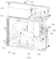
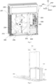
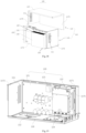
- an embodiment of a first aspect of the present application provides an air-source heat pump air conditioner, which includes a housing 200, an electric control box 100, an air side heat exchange mechanism, a hydraulic mechanism, and a compressor 400.
- the housing 200 is internally provided with a first partition 201 and a second partition 202.
- the first partition 201 divides the housing 200 into an upper chamber 203 and a lower chamber
- the second partition 202 divides the lower chamber into a first chamber 204 and a second chamber 205.
- the electric control box 100 is arranged inside the upper chamber 203
- the air side heat exchange mechanism is arranged inside the first chamber 204
- the hydraulic mechanism and the compressor are arranged inside the second chamber 205.
- the housing 200 is an installation carrier for the members of the air-source heat pump air conditioner, and it can be of any shape.
- the housing 200 has a rectangular shape, and includes a top wall, a bottom wall 206, and side walls. Upper ends of the side walls are connected to the top wall, and lower ends of the side walls are connected to the bottom wall 206.
- the side walls cooperate with the top wall and the bottom wall 206 to enclose a chamber for accommodating functional members.
- the side walls include a rear side wall, a left side wall, a front side wall, and a right side wall, which are connected end-to-end in sequence.
- the side walls can usually be designed in a detachable manner.
- the definitions involved in this embodiment are based on the orientation of the air-source heat pump air conditioner after it is installed in the usage environment.
- the side of the air-source heat pump air conditioner that is near buildings such as a wall is the rear side
- the side opposite to the rear side is the front side
- the other horizontal direction perpendicular to the front-and-rear direction is the left-and-right direction
- the vertical direction is the up-and-down direction.
- the top wall is located above the bottom wall 206
- the orientational words in the rear side wall, left side wall, front side wall and right side wall have certain orientational definitions.
- the rear side wall is the side wall of the housing 200 that faces the rear
- the left side wall is the side wall of the housing 200 that faces the left
- the front side wall is the side wall of the housing 200 that faces the front
- the right side wall is the side wall of the housing 200 that faces the right.
- the air side heat exchange mechanism includes an air side heat exchanger 310, which is arranged inside the first chamber 204.
- the hydraulic mechanism includes a water side heat exchanger 600, which is arranged inside the second chamber 205.
- the air-source heat pump air conditioner can also be provided with a fan blade assembly 300 corresponding to the air side heat exchanger 310, and the fan blade assembly 300 is arranged inside the first chamber 204.
- the air side heat exchanger 310 can be arranged outside of the fan blade assembly 300, as shown in FIGS. 1 and 2 .
- the air side heat exchanger 310 is arranged in an L-shape inside the first chamber 204, and is located near the left side wall and the rear side wall that form the first chamber 204.
- the air side heat exchanger 310 can be a finned heat exchanger.
- the fan blade assembly 300 is used to promote air flow.
- the fan blade assembly 300 can be an assembly such as an axial flow fan, which includes fan blades and a driving member.
- the driving member can be in the form of a motor in cooperation with a transmission member.
- the driving member is connected to the fan blades to drive them to rotate, so that air flows around the air side heat exchanger 310, allowing the air side heat exchanger to come into contact with the flowing air to improve heat exchange efficiency.
- the water side heat exchanger 600 includes a refrigerant pipeline and a water flow pipeline.
- an expansion valve can also be arranged between the refrigerant pipeline of the water side heat exchanger 600 and the air side heat exchanger 310 to convert high-pressure gas into low-pressure gas.
- the air-source heat pump air conditioner can achieve both cooling and heating.
- the compressor 400 delivers high-temperature and high-pressure gaseous refrigerant to the refrigerant pipeline of the water side heat exchanger 600.
- the refrigerant in the refrigerant pipeline exchanges heat with the water flow in the water flow pipeline.
- the refrigerant pipeline outputs low-temperature and high-pressure (the low temperature is defined relative to the high temperature, and the low temperature can also be considered as conventional medium temperature) liquid refrigerant.
- the low-temperature and high-pressure liquid refrigerant is converted into low-pressure liquid refrigerant through the expansion valve.
- the liquid refrigerant vaporizes and absorbs heat in the air side heat exchanger 310 before entering the compressor 400, completing a heating and heat exchange process.
- the compressor 400 delivers high-temperature and high-pressure gaseous refrigerant to the refrigerant pipeline of the air side heat exchanger 310.
- the refrigerant in the air side heat exchanger 310 exchanges heat with air, and then low-temperature and high-pressure liquid refrigerant is output.
- the low-temperature and high-pressure liquid refrigerant is converted into low-pressure liquid refrigerant through the expansion valve.
- the liquid refrigerant flows into the refrigerant pipeline of the water side heat exchanger 600.
- the liquid refrigerant exchanges heat with the water flow in the water flow pipeline, vaporizes, absorbs heat, and then enters the compressor 400, completing a cooling and heat exchange process.
- the air side heat exchanger is equivalent to an evaporator, and in the cooling process, the air side heat exchanger is equivalent to a condenser.
- the switching between cooling and heating processes can be achieved by connecting a four-way valve to a refrigerant outlet of the compressor.
- the water flow pipeline of the water side heat exchanger 600 can also be connected with a water pump 500 and a water delivery pipeline.
- the water delivery pipeline is communicated with the water flow pipeline of the water side heat exchanger 600, and the water pump is arranged on the water delivery pipeline.
- the water pump 500 can drive water to circulate in the water flow pipeline, and can also be arranged in the second chamber 205.
- the housing 200 is divided into the upper chamber 203 and the lower chamber by the first partition 201, and the lower chamber is further divided into the first chamber 204 and the second chamber 205 by the second partition 202, so that members such as the electric control box 100, the air side heat exchange mechanism, the hydraulic mechanism, and the compressor 400 can be arranged in separate chambers, making the installation convenient and improving space utilization.
- the electric control box 100 By arranging the electric control box 100 in the upper chamber 203, arranging the air side heat exchange mechanism in the first chamber 204, and arranging the hydraulic mechanism and the compressor in the second chamber 205, the disassembly and maintenance of the electric control box 100 is facilitated, and the centers of gravity of the air side heat exchange mechanism, the hydraulic mechanism and the compressor 400 are made lower, with better stability.
- the whole machine has a compact structure and occupies less space.
- the second chamber 205 and the first chamber 204 can be arranged in sequence in the vertical direction or horizontal direction.
- the second chamber 205 and the first chamber 204 are arranged side by side in the horizontal direction.
- the second chamber 205 and the first chamber 204 can be arranged in sequence in the left-and-right direction of the housing 200; the first chamber 204 can be located on the left side of the second chamber 205, and the first chamber 204 can also be located on the right side of the second chamber 205.
- the second chamber 205 and the first chamber 204 can also be arranged in sequence in the front-and-rear direction of the housing 200; the first chamber 204 can be located on the rear side of the second chamber 205, and the first chamber 204 can also be located on the front side of the second chamber 205.
- the second chamber 205 is located on the right side of the first chamber 204, that is, the first chamber 204 is formed on the left side of the second partition 202, and the second chamber 205 is formed on the right side of the second partition 202.
- the first partition 201 is fixed to inner side surfaces of the side walls, the upper chamber 203 is formed between the top wall and the first partition 201, and the lower chamber is formed between the bottom wall 206 and the first partition 201; the second partition 202 is connected between the first partition 201 and the bottom wall 206; the first chamber 204 is formed between the second partition 202 and a side wall (the left side wall and a part of the rear side wall located on the left side of the second partition 202) located on one side of the second partition 202, and the second chamber 205 is formed between the second partition 202 and a side wall (the right side wall and a part of the rear side wall located on the right side of the second partition 202) located on the other side of the second partition 202.
- the top wall, the bottom wall 206 and the first partition 201 are arranged in parallel, the side walls are arranged perpendicular to the bottom wall 206 and the top wall, and the second partition 202 is arranged perpendicular to the top wall and the bottom wall 206, thereby forming a relatively square first chamber 204 and second chamber 205, which facilitates the arrangement and installation of corresponding members.
- the bottom wall 206, the top wall and the first partition 201 may not be arranged in parallel.
- the first partition 201 may be inclined, while the bottom wall 206 and the top wall are horizontally arranged;
- the side walls are also not limited to being perpendicular to both the bottom wall 206 and the top wall, for example, the side walls may be inclined;
- the second partition 202 may also be inclined.
- the water side heat exchanger 600 can be placed on the bottom wall 206 corresponding to the second chamber 205, and the compressor 400 can be placed above the water side heat exchanger 600.
- a first support member 210 is also provided inside the housing 200.
- the first support member 210 can be in the form of a plate, a rod, or a frame structure.
- the second partition 202 is connected to the first support member 210, and an installation space for installing the water side heat exchanger 600 is formed between the bottom wall 206 and a lower side of the first support member 210.
- An upper side of the first support member 210 is provided with a first support position 2101 for installing the compressor 400.
- the water side heat exchanger 600 can slide laterally along the bottom wall 206 into the installation space, and the compressor 400 can be fixed to the first support position 2101 by screws.
- the second partition 202 is installed on the bottom wall 206 and located inside the housing 200, that is, the second partition 202 is located on a side surface of the bottom wall 206 that faces upward. By installing the second partition 202 on the bottom wall 206, the bottom wall 206 can provide support for the second partition 202.
- the second partition 202 There are various structural forms of the second partition 202, including a rectangular plate with a rectangular cross section, a T-shaped plate with a T-shaped cross section, a U-shaped plate with a U-shaped cross section, a H-shaped plate with a H-shaped cross section, and a L-shaped plate with a L-shaped cross section, etc.
- the second partition 202 can be a structure that is integrally formed with the bottom wall 206, or it can be installed on the bottom wall 206 through welding, screw fixation, snap-fit, etc.
- the structural form of the first support member 210 can also be configured in various ways as needed, such as a rectangular plate, an elliptical plate, an irregular plate, and so on.
- the second partition 202 and the first support member 210 can be fixed to each other.
- the second partition 202 and the first support member 210 may be connected in a non-detachable way, which can be achieved by welding the second partition 202 and the first support member 210, or by integrally forming the second partition 202 and the first support member 210.
- the second partition 202 and the first support member 210 may also be connected in a detachable way, which can be achieved by screwing or snap-fitting the second partition 202 with the first support member 210, or by abutting and supporting the first support member 210 on the second partition 202, etc.
- the first support member 210 can be connected to the second partition 202 in the middle of the first support member 210, and two ends of the first support member 210 are respectively positioned away from the second partition 202; at this time, the first support member 210 and the second partition 202 form a cross shaped cross arrangement.
- the first support member 210 can be connected to the second partition 202 at one end of the first support member 210, and the other end of the first support member 210 is positioned away from the second partition 202; at this time, the first support member 210 is located on one side of the second partition 202.
- Arranging the first support member 210 on one side of the second partition 202 is more advantageous for the arrangement of members of the air-source heat pump air conditioner, so this embodiment is mainly explained with the first support member 210 being connected to the second partition 202 at one end of the first support member 210.
- the first support member 210 is supported by the second partition 202, and under the support of the second partition 202, one end of the first support member 210 that is away from the second partition 202 can be suspended and can support the compressor 400. That is, the first support member 210 can support the compressor 400 by solely relying on the action of the second partition 202. In other words, the first support member 210 can independently support the compressor 400 under the support of the second partition 202. Therefore, the end of the first support member 210 that is away from the second partition 202 may not be provided with a corresponding support structure. Accordingly, a side of the installation space that is away from the second partition 202 will not be restricted by the support structure.
- the water side heat exchanger 600 can enter and exit the installation space from the side away from the second partition 202, which facilitates the disassembly and installation of the water side heat exchanger 600 in the second chamber 205, and improves the convenience and efficiency of maintenance and replacement operations of the water side heat exchanger 600 and the compressor 400.
- the second partition 202 of this embodiment is arranged perpendicular to the bottom wall 206, and the first support member 210 is arranged in parallel to the bottom wall 206.
- the bottom wall 206 is arranged in the horizontal direction, and the second partition 202 extends in the vertical direction (i.e., in the up-and-down direction). One end of the second partition 202 is fixedly connected to the bottom wall 206.
- the first support member 210 is arranged in the horizontal direction and located above the bottom wall 206. One end of the first support member 210 is connected to the second partition 202.
- the space formed for installing the water side heat exchanger 600 is relatively square by arranging the second partition 202 vertically and arranging the first support member 210 and the bottom wall 206 in parallel, which is advantageous for the installation of the water side heat exchanger 600.
- the first support member 210 and the bottom wall 206 are arranged in parallel, that is, horizontally, which also facilitates the stable support of the compressor 400.
- the arrangement of the second partition 202 and the first support member 210 in this embodiment is not limited to the way in which the second partition 202 is perpendicular to the bottom wall 206, and the first support member 210 is parallel to the bottom wall 206. According to actual spatial arrangement requirements, the second partition 202 can also be inclined on the bottom wall 206, and the first support member 210 can also be inclined.
- multiple fixed positions are provided on the second partition 202, and the number of fixed positions is not less than three. Successive connecting lines of the multiple fixed positions are arranged in a polygonal shape, that is, at least one of the multiple fixed positions is non-collinear with the other two of the multiple fixed positions in the horizontal direction.
- one of the fixed positions is non-collinear with the other two of the fixed positions in the horizontal direction, so that at least a triangular support can be formed, and when the first support member 210 is arranged on the second partition 202, even if the end of the first support member 210 that is away from the second partition 202 is suspended, the first support member 210 still has good support stability.
- there can be three fixed positions provided on the second partition 202 which are scattered on the same horizontal plane and connected in sequence to form a triangle, i.e., the three fixed positions are not collinear.
- the multiple fixed positions are not limited to being scattered on the same horizontal plane, and they can also have a certain height difference in the vertical direction, as long as they can stably support the first support member 210.
- the fixed positions may have various structures. Specifically, the fixed positions can be protrusions protruding from the second partition 202. At this time, the first support member 210 can be supported on the protrusions, and the first support member 210 can be fixedly connected to the protrusions by screws or other means. The first support member 210 can also simply abut on the protrusions through the support of the protrusions.
- the fixed positions can also be grooves 213 provided on the second partition 202. At this time, the first support member 210 is provided with bulges corresponding to the grooves 213, and the first support member 210 is connected to the second partition 202 by snap-fitting the bulges in the grooves 213.
- the fixed positions can also be fixed holes provided on the second partition 202, and the first support member 210 is directly connected to the second partition 202 by passing screws and the like through the corresponding structures on the first support member 210 and the fixed holes.
- the second partition 202 includes a second support surface 2022 and a first support surface 2021.
- the second support surface 2022 and the first support surface 2021 are connected to each other and arranged at an angle.
- the first support surface 2021 is provided with a first support sub part 2023
- the second support surface 2022 is provided with a second support sub part 2024.
- the second support sub part 2024 and the first support sub part 2023 are located in a space formed by the second support surface 2022 and the first support surface 2021, respectively.
- the first support sub part 2023 is connected to the first support surface 2021
- the second support sub part 2024 is connected to the second support surface 2022.
- the second support sub part 2024 and the first support sub part 2023 form a support part for supporting the first support member 210.
- the second support surface 2022 and the first support surface 2021 can both extend in the vertical direction, and one side edge of the first support surface 2021 and one side edge of the second support surface 2022 are aligned and connected.
- the first support surface 2021 and the second support surface 2022 are arranged perpendicular to each other.
- the first support sub part 2023 can be installed on the first support surface 2021 by snap-fit, welding, and screwing, etc.
- the second support sub part 2024 can also be installed on the second support surface 2022 by snap-fit, welding, and screwing, etc.
- the first support member 210 can be installed on the first support sub part 2023 and the second support sub part 2024 by screwing, welding and snap-fit, etc.
- a support surface is provided above the first support sub part 2023, and a support surface is also provided above the second support sub part 2024.
- the support surfaces extend horizontally and are in horizontal abutment with the first support member 210, which is equivalent to that the support surfaces form multiple fixed positions.
- the extending length of the first support sub part 2023 in the direction perpendicular to the second support surface 2022 is relatively long, and the second support sub part 2024 is arranged at one end of the second support surface 2022 that is away from the first support surface 2021.
- two screw holes 2025 are provided on the first support sub part 2023, and one screw hole 2025 is provided on the second support sub part 2024.
- the first support member 210 is fixed to the second support sub part 2024 and the first support sub part 2023 by passing screws through the three screw holes 2025.
- the fixed positions can be set on the second support sub part 2024 and the first support sub part 2023, or the second support sub part 2024 and the first support sub part 2023 themselves form multiple fixed positions.
- the fixed position formed on the first support sub part 2023 is a first fixed position
- the fixed position formed on the second support sub part 2024 is a second fixed position.
- the water pump 500 is arranged above the water side heat exchanger. Specifically, the water pump 500 can be located on one side of the compressor 400 in the horizontal direction, that is, the water pump 500 and the compressor 400 are arranged in sequence in the horizontal direction.
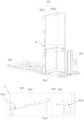
- the first support member 210 of this embodiment is also provided with a second support position 2102, which is arranged side by side with the first support position 2101 in the horizontal direction, and which is used for installing the water pump.
- the first support member 210 is roughly arranged in an L-shape.
- a wider end of the first support member 210 is the first support position 2101, and is used for installing the compressor 400; a narrower end of the first support member 210 is the second support position 2102, and is used for installing the water pump 500.
- first support position 2101 and the second support position 2102 are formed by the first support member 210, so that the compressor and the water pump (i.e., the water pump 500 and the compressor 400) can be installed on the first support member 210 simultaneously, which is advantageous for the compact arrangement of the members, thereby reducing the volume and occupied space of the housing 200.
- the compressor and the water pump i.e., the water pump 500 and the compressor 400
- the second support position 2102 can be set on a side of the first support position 2101 that is away from the second partition 202, that is, the second support position 2102 can be set near the side wall of the housing 200, so that the water pump 500 can be disassembled and repaired after removing the side wall of the housing 200.
- the air-source heat pump air conditioner of this embodiment is also provided with a second support member 220 and a first fixing member 221.
- the first fixing member 221 is arranged on the second support member 220, that is, the water pump 500 is installed on the second support member 220.
- the water pump 500 can be specifically fixed to the second support member 220 by screws.
- the first support member 210 is provided with a second fixing member 211, and the second support member 220 can slide along a plate surface of the first support member 210 and can slide to the second support position 2102. After the second support member 220 slides to the second support position 2102, the second support member 220 is matched and fixed to the first support member 210 through the first fixing member 221 and the second fixing member 211.
- the second support member 220 can be in the form of a plate, a rod, or a frame structure, etc.
- the second support member 220 can slide along the plate surface of the first support member 210 relative to the first support member 210, that is, the second support member 220 can slide horizontally and move to the second support position 2102. In this way, the installation of the water pump 500 is not affected by the compressor 400 or the upper and lower space.
- Other members can be arranged above or below the water pump 500, which is advantageous for the miniaturization design of the air-source heat pump air conditioner.
- the water pump 500 is first fixed on the second support member 220, then the second support member 220 is pushed to slide along the plate surface of the first support member 210 so that the second support member 220 slides to the second support position 2102, and then the second fixing member 211 and the first fixing member 221 are matched and fixed.
- the second fixing member 211 is detachably connected to the first fixing member 221. In this way, when it is necessary to disassemble the water pump 500, the first fixing member 221 and the second fixing member 211 are detached, and then the second support member 220 slides out of the second support position 2102 along the plate surface of the first support member 210 so that the water pump 500 can be removed.
- the second fixing member 211 and the first fixing member 221 can be detachably connected in many ways, such as snap-fit connection, threaded connection, etc.
- the first fixing member 221 can be a part of the structure of the second support member 220 itself, or an additional member arranged on the second support member 220.
- the second fixing member 211 can also be a part of the structure of the first support member 210 itself, or an additional member arranged on the first support member 210.
- the first fixing member 221 and the second fixing member 211 can be connected to each other in the horizontal direction for easy installation from the side.
- the air-source heat pump air conditioner further includes a first fastener for detachably connecting the first fixing member 221 with the second fixing member 211. Specifically, after the second support member 220 slides to the second support position 2102, the second fixing member 211 and the first fixing member 221 abut with each other in the horizontal direction. The first fastener is used to pass through the second fixing member 211 and the first fixing member 221 in the horizontal direction, so that the second fixing member 211 and the first fixing member 221 can be fixedly connected in a detachable manner.
- one end of the second support member 220 is provided with a first edgefold, which protrudes downward and forms the first fixing member 221.
- One end of a circumferential side wall of the first support member 210 itself forms the second fixing member 211.
- the first fastener is a screw
- threaded holes 214 are correspondingly provided on the first fixing member 221 and the second fixing member 211, and the screw is inserted into the threaded holes 214.
- the first fixing member 221 abuts with the second fixing member 211, that is, the first edgefold abuts with the circumferential side wall of the first support member 210.
- the second support member 220 can be fixed to the first support member 210 by passing the screw through the first edgefold and the circumferential side wall of the first support member 210 that abuts with the first edgefold.
- the first support member 210 is further provided with a first mating member 212
- the second support member 220 is provided with a second mating member 222.
- the second mating member 222 can cooperate with the first mating member 212 to enable the second support member 220 to slide along a certain direction (defined as a first direction) of the plate surface of the first support member 210, and to restrict the second support member 220 from moving in other directions, that is, directions perpendicular to the first direction.
- the other directions perpendicular to the first direction include a second direction in the horizontal direction, and the vertical direction.
- the second mating member 222 and the first mating member 212 can provide good guidance for the sliding of the second support member 220 on the first support member 210, allowing the second support member 220 to quickly move to the second support position 2102 in the first direction, which can not only position the installation position of the second support member 220, but also allows the threaded holes 214 on the first fixing member 221 and the second fixing member 211 to be positioned and aligned correspondingly when the second support member 220 slides to the second support position 2102, facilitating the connection of the first fixing member 221 and the second fixing member 211 using the screw.
- first mating member 212 with the second mating member 222
- second mating member 222 which can specifically be a guide rail mating with a sliding block.
- a guide rail can be arranged on the first support member 210
- a sliding block can be arranged on the second support member 220.
- the sliding block can be snap-fitted onto the guide rail and can move along the guide rail in the first direction.
- the first mating member 212 is provided with a groove 213, and a groove opening of the groove 213 is oriented toward the second direction of the plate surface of the first support member 210, which is perpendicular to the first direction.
- the second mating member can be slidably inserted into the groove 213.
- first direction and the second direction are two directions perpendicular to each other in the horizontal plane.
- the groove opening of the groove 213 is arranged toward the second direction, so that upper and lower parts of the groove 213 can limit the movement of the second mating member in the up-and-down direction.
- the groove 213 can also position the second mating member in the second direction, so that the second mating member can mostly slide only in the first direction.
- the first mating member 212 includes a connection part 2121 and a restriction part 2122.
- the connection part 2121 is fixedly connected to the first support member 210, and one end of the connection part 2121 is folded upward to form a folded part 2123.
- the restriction part is connected to the folded part 2123, and is arranged in parallel to the connection part 2121.
- the folded part 2123, the restriction part 2122, and the connection part 2121 form the groove 213, and the groove opening of the groove 213 is arranged opposite to the folded part 2123.
- the restriction part and the connection part 2121 are not connected at the left end in the first direction, that is, the left end is a through opening.
- the second mating member 222 can be inserted into the groove 213 from the left end of the groove 213.
- the second mating member 222 can be a structure such as a downward transverse bending edge of the second support member 220.
- the number of the first mating member 212 is two, and the two first mating members 212 are spaced apart in the second direction.
- Two second mating members are correspondingly provided on the second support member 220.
- the groove openings of the two first mating members 212 can face each other.
- the two second mating members 222 can be arranged in the grooves 213 of the two first mating members 212 and face each other. Referring to FIG. 10 , the groove openings of the two first mating members 212 can also face away from each other.
- the two second mating members 222 can be arranged in the grooves 213 of the two first mating members 212 and face away from each other.
- This embodiment will mainly be described using an example in which the groove openings of the two first mating members 212 face away from each other.
- the second mating member 222 can enter the first mating member 212 only from the through opening position at the left end of the groove 213 of the first mating member 212.
- the second support member 220 cannot move in the second direction or in the vertical direction, and can only slide in the first direction.
- a lower edge of the end of the second support member 220 that is not provided with the first fixing member 221 should be higher than a lower edge of the first fixing member 221, so that the first fixing member 221 can abut with the second fixing member 211 from the side.
- the specific process of installing the water pump 500 is as follows: the water pump 500 is installed on the second support member 220, with the end of the second support member 220 that is not provided with the first fixing member 221 facing forward and the end provided with the first fixing member 221 facing backward; then the second support member 220 is pushed to slide in the first direction; when the second support member 220 slides to the second support position 2102, the first fixing member 221 and the second fixing member 211 abut with each other, and then the first fixing member 221 and the second fixing member 211 are fixedly connected by passing a screw transversely into the threaded holes 214 of the first fixing member 221 and the second fixing member 211. When the second support member 220 slides to the second support position 2102, the end of the second support member 220 that is not provided with the first fixing member 221 is located on the upper side of the first support member 210.
- the second support member 220 When installing and disassembling the water pump 500, it is only required to remove the second support member 220. Due to the mating action between the first mating member 212 and the second mating member 222, only one screw is needed to fix the first fixing member 221 and the second fixing member 211 in actual operation, which can complete the fastening of the second support member 220. The operation is convenient and quick, and the screw can be assembled transversely to fasten the first fixing member 221 and the second fixing member 211. Compared with the installation method of inserting the screw from top to bottom or from bottom to top, the operation is more convenient.
- the second support member 220 is installed and disassembled through transverse sliding, and the second mating member and the first mating member can be mated and pressed up and down tightly.
- the second support member 220 only needs to slide horizontally, which improves the efficiency of disassembling and installing the water pump 500.
- the second chamber 205 is divided into upper and lower parts by the first support member 210.
- the lower part is used to arrange the water side heat exchanger 600
- the upper part is used to arrange the compressor 400 and the water pump 500, further improving the space utilization of the housing and facilitating the miniaturization design of the air-source heat pump air conditioner.
- the air-source heat pump air conditioner of this embodiment may further include a third support member 230, one end of which is connected to the bottom wall 206, and the other end of which is connected to the first support member 210.
- the third support member 230 can be in the form of a rod, a plate, or a frame structure.
- the third support member 230 can be detachably connected to both the first support member 210 and the bottom wall 206.
- the third support member 230 can be connected to the bottom wall 206 through snap-fit or screws, and the third support member 230 can also be connected to the first support member 210 through snap-fit, screws, etc.
- the third support member 230 can assist in supporting the first support member 210, so that the first support member 210 has higher support stability.
- the third support member 230 can be separately and transversely installed and disassembled. After the third support member 230 is disassembled, the fixed position or support part on the second partition 202 can still support the first support member 210 and all the components above it. In other words, after the third support member 230 is disassembled, the first support member 210 can still stably support the compressor 400 and the water pump 500.
- the third support member 230 when it is necessary to disassemble the water side heat exchanger 600, the third support member 230 can be disassembled, and then the water side heat exchanger 600 can be disassembled separately. This operation will not affect other components, and can improve the efficiency of the installation, disassembly and maintenance of the water side heat exchanger 600.
- a gasket for supporting the water pump 500 can also be provided on the second support member 220 in this embodiment.
- the first chamber 204 and the second chamber 205 there are certain gaps between the first chamber 204 and the second chamber 205. These gaps can be small gaps originally formed at the connection between the second partition 202 and the first partition 201 or the bottom wall 206, and they are not required to be made artificially.
- the gaps allow air to flow between the first chamber 204 and the second chamber 205.
- the water pump 500 can also be provided with a cooling fan to quickly dissipate heat from the water pump 500.
- a corresponding grille-like vent can be provided on the side wall of the housing 200 that corresponds to the second chamber 205 to facilitate air flow.
- the water side heat exchanger 600 of the air-source heat pump air conditioner in this embodiment can be a double-pipe heat exchanger, which is spirally wound on the bottom wall 206 in the vertical direction, i.e., the up-and-down direction.
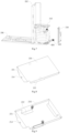
- a third fixing member 240 is provided on the bottom wall of the second chamber 205, i.e., at a position of the bottom wall 206 that corresponds to the second chamber 205, and the third fixing member 240 is used to fix the water side heat exchanger 600.
- a fourth fixing member 250 is fixed on the water side heat exchanger 600, and the water side heat exchanger 600 can slide along the bottom wall 206 of the second chamber 205.
- the third fixing member 240 and the fourth fixing member 250 are mated and connected to fix the water side heat exchanger 600 on the bottom wall 206 of the second chamber 205.
- the third fixing member 240 includes a first limiting part 241 and a first installation part 242, both of which are fixed to the bottom wall 206.
- the first limiting part 241 is provided with a pressing groove, and a groove opening of the pressing groove is horizontally arranged.
- the fourth fixing member 250 includes a second limiting part 251 and a second installation part 252, both of which are fixedly connected to the water side heat exchanger 600. Under the sliding action of the water side heat exchanger 600 along the bottom wall 206 of the second chamber 205, the second limiting part 251 can be inserted into the pressing groove, and the second installation part 252 can be mated and fixedly connected to the first installation part 242.
- the second limiting part 251 When the second limiting part 251 is inserted into the pressing groove, the second limiting part 251 can be pressed tightly under the action of the first limiting part 241, so that the water side heat exchanger 600 cannot move vertically.
- the first installation part 242 and the second installation part 252 are fixedly connected, so that the water side heat exchanger 600 can be completely fixed on the bottom wall 206.
- the numbers of the second limiting parts 251 and the first limiting parts 241 can each be multiple, with multiple first limiting parts 241 and multiple second limiting parts 251 being set in a one-to-one correspondence.
- the first installation part 242 and the second installation part 252 can be detachably connected by snap-fit, screwing and the like to facilitate the disassembly of the water side heat exchanger 600.
- the first installation part 242 and the second installation part 252 are fixedly connected by a second fastener, which may be a screw.
- the numbers of the first installation part 242 and the second installation part 252 can each be one, or be multiple in a one-to-one correspondence. In a case where there are multiple (two or more) first limiting parts 241 mated with the second limiting parts 251 for pressing, only one first installation part 242 and one second installation part 252 may be provided, so that the water side heat exchanger 600 can be fixed by using one screw, making the operation convenient and quick.
- the second limiting part 251 and the second installation part 252 of the fourth fixing member 250 can be separate structures or an integrated structure. Referring to FIG. 14 , when the second limiting part 251 and the second installation part 252 of the fourth fixing member 250 are of an integrated structure, the second limiting part 251 and the second installation part 252 are configured into an L-shaped plate.
- the second installation part 252 is vertically arranged and fixedly connected to an inner side of the water side heat exchanger 600.
- the second limiting part 251 is arranged on a lower side of the second installation part 252 and is roughly horizontally arranged.
- the second installation part 252 can be fixedly connected to the first installation part 242 through a horizontally penetrating screw.
- the number of the fourth fixing member 250 is multiple, and the second limiting part 251 of each fourth fixing member 250 can be mated with one first limiting part 241 for pressing and fixing.
- the multiple fourth fixing members 250 it is possible for only one second installation part 252 to be mated with the first installation part 242 and fastened through the second fastener.
- first installation part 242 and the second installation part 252 can abut in the horizontal direction, so that the screw can penetrate into the first installation part 242 and the second installation part 252 in the horizontal direction, improving the convenience of assembly.
- the third support member 230 can be transversely disassembled and there is no influence on other components after disassembly, the water side heat exchanger 600 in the whole machine is easy to disassemble without affecting other components.
- first limiting part 241 and the first installation part 242 of the third fixing member 240 can be directly arranged on the bottom wall 206, or on a fixed plate 243, which is fixedly connected to the bottom wall 206.
- the rear side wall, the left side wall, the front side wall, and the right side wall of the housing 200 in this embodiment can all be detachably arranged, so as to facilitate the disassembly of internal members adjacent to the side walls by disassembling the corresponding side walls.
- the right side wall is detachably arranged, so that when it is necessary to disassemble the water pump 500, the compressor 400, or the water side heat exchanger 600, the right side wall can be removed from the housing 200, and then the water pump 500, the compressor 400, or the water side heat exchanger 600 can be disassembled, making the operation convenient and quick.
- the water delivery pipeline connected to the water flow pipeline connected to the water side heat exchanger 600 includes a water inflow pipe 510 and a water outflow pipe 520.
- the water inflow pipe 510 is connected to a water inlet of the water flow pipeline, and the water outflow pipe 520 is connected to the water inlet of the water flow pipeline.
- the water pump 500 is arranged on the water outflow pipe 520.
- the water inflow pipe 510, the water side heat exchanger 600, the water pump 500, and the water outflow pipe 520 are arranged in this order in the whole machine (the water outflow pipe 520 can be divided into a water pump water inflow pipe, a water pump water outflow pipe, and a whole machine water outflow pipe; correspondingly, from water inflow to water outflow, the water inflow pipe 510, the water side heat exchanger 600, the water pump water inflow pipe, the water pump 500, the water pump water outflow pipe, and the water outflow pipe 520 are arranged in this order in the whole machine).
- Water inflow and outflow connecting pipes of the water pump 500 can be soft connecting pipes for easy installation and disassembly.
- the right side wall or left side wall corresponding to the second chamber 205 is provided with a pipe inlet and a pipe outlet.
- the pipe inlet can be used to arrange the water inflow pipe 510 connected to the water side heat exchanger 600
- the pipe outlet can be used to arrange the water outflow pipe 520 connected to the water side heat exchanger 600.
- the second chamber 205 is formed on the right side of the housing 200.
- the right side wall corresponds to the second chamber 205, and the right side wall is provided with the pipe inlet and the pipe outlet.
- the water inflow pipe 510 is arranged in the pipe inlet, and the water outflow pipe 520 is arranged in the pipe outlet.
- the air-source heat pump air conditioner can be installed closer to the wall, and the operation space for connecting the water inflow pipe 510 and the water outflow pipe 520 to the circulating water pipe in the home is larger, making the operation more convenient.
- the third support member 230 can be a part of the right side wall of the housing 200, which can save the consumables of the housing 200 and also facilitate the miniaturization arrangement of the housing 200.
- the pipe outlet is arranged on the third support member 230.
- the water inflow pipe 510 can be in clearance fit with the pipe inlet, so that the side wall where the pipe inlet is located can be separately disassembled without disassembling the water inflow pipe 510.
- the water outflow pipe 520 can be in clearance fit with the pipe outlet, so that the side wall where the pipe outlet is located can be separately disassembled without disassembling the water outflow pipe 520.
- the position of a water inlet of the water inflow pipe 510 is higher than the highest position of the water flow pipeline of the water side heat exchanger 600 and the highest position of the water inflow pipe 510, and is located at the highest point of the water inflow pipe 510; the position of a drainage outlet of the water outflow pipe 520 is lower than the lowest position of the water flow pipeline and the lowest position of the water inflow pipe 510, and is located at the lowest point of the water outflow pipe 520.
- the electric control box 100 of this embodiment includes a box body 110 and an electric control assembly 120.
- the box body 110 can be a plastic box to reduce the weight of the box body.
- the box body 110 can have any shape, which can specifically be rectangular, cylindrical, and so on.
- the electric control assembly 120 is arranged inside the box body 110, including weak electricity elements for intelligent control of the air-source heat pump air conditioner and strong electricity elements for converting the strong electricity of the air-source heat pump air conditioner.
- the electric control assembly 120 includes a filtering board 122, a main control board 123, and a module board 121.
- the main control board 123 is a circuit board used to control the air-source heat pump air conditioner; it is a weak electricity element and has functions such as signal acquisition, signal processing, and whole machine control, etc.
- the filtering board 122 can process the input and output strong electricity signals to prevent external power grid from interfering with the operation of the air-source heat pump air conditioner, and to prevent electrical signals output from the interior of the air-source heat pump air conditioner from interfering with the power grid.
- the module board 121 has functions of variable frequency drive control of the compressor 400 and AC/DC conversion control, etc.; it can achieve variable frequency operation of the air-source heat pump air conditioner, as well as AC/DC conversion.
- the electric control assembly 120 inside the electric control box 100 generates a significant amount of heat during operation, so it is usually necessary to dissipate heat from the electric control box 100.
- the housing 200 is provided with a whole machine air outlet, a whole machine air inlet, and a heat dissipation air inlet.
- the box body 110 is provided with a first air outlet 112 and a first air inlet 111.
- the first air outlet 112 is located near the air inflow end of the fan blade assembly 300 relative to the first air inlet 111, that is, the first air inlet 111 corresponds to the heat dissipation air inlet and is communicated with it.
- the first air outlet 112 faces the air inflow side of the fan blade assembly 300 and is communicated with it.
- the air outflow side of the fan blade assembly 300 is arranged corresponding to the whole machine air outlet and is communicated with it.
- the whole machine air outlet and the whole machine air inlet are usually arranged opposite to each other.
- the whole machine air inlet is arranged corresponding to the air inflow end of the fan blade assembly 300, and is usually arranged on the rear side of the housing 200.
- the whole machine air outlet is arranged corresponding to the air outflow end of the fan blade assembly 300, and is usually arranged on the front side of the housing 200.
- an airflow A formed by the air flows in from the heat dissipation air inlet, sequentially passes through the first air inlet 111, the box body 110, the first air outlet 112 and the fan blade assembly 300, and then flows out from the whole machine air outlet.
- the air can be promoted to quickly flow into the box body 110 from the first air inlet 111 and flow out from the first air outlet 112.
- the airflow A formed by the air quickly flows through the box body 110, so that the heat inside the box body 110 can be quickly taken away, improving the heat dissipation effect on the electric control box 100.
- the air-source heat pump air conditioner also includes a first water blocking assembly 260, which is arranged corresponding to the first air outlet 112 to block the water thrown out during the rotation of the fan blade assembly 300 from flowing into the first air outlet 112.
- the first water blocking assembly 260 is correspondingly arranged at the first air outlet 112, and it can prevent water thrown out by the fan blade assembly 300 from entering the first air outlet 112 in rainy weather situations and the like, ensuring the waterproof performance of the electric control box 100.
- a through opening (defined as a first through opening 2012 for ease of description) is formed on the first partition 201.
- the electric control box 100 is arranged in the upper chamber 203, and the first air outlet 112 is arranged corresponding to the first through opening 2012.
- the first air outlet 112 is communicated with the first chamber 204 through the first through opening 2012.
- the fan blade assembly 300 is arranged in the first chamber 204, and the air inflow end is communicated with the first through opening 2012 and is arranged corresponding to the first through opening 2012.
- the first water blocking assembly 260 in this embodiment is arranged corresponding to the first through opening 2012 or the first air outlet 112, that is, the first water blocking assembly 260 can be connected to the box body 110 of the electric control box 100 or to the first partition 201.
- a first water blocking plate 261 cooperates with the first through opening 2012 or the first air outlet 112 to allow the airflow A to pass through and prevent the fan blade assembly 300 from throwing rainwater into the electric control box 100.
- the first water blocking assembly 260 is arranged on a bottom plate 116.
- the first water blocking assembly 260 includes a first water blocking plate 261, which is arranged on an airflow path of the first air outlet 112 and intersects with the flow direction of the airflow flowing out through the first air outlet 112.
- a projection of the first air outlet 112 toward the first water blocking plate 261 falls onto an inner side of a circumferential edge of the first water blocking plate 261.
- the first through opening 2012 is arranged corresponding to the first air outlet 112, and the bottom plate 116 is abutted and fixed with the first partition 201.
- the circumferential edge of the first water blocking plate 261 includes a first edge part and a second edge part.
- the first water blocking plate 261 is connected to the bottom plate 116 through the first edge part, and an airflow channel is formed between the second edge part and the first partition 201.
- the airflow flowing out through the first air outlet 112 flows toward the fan blade assembly 300 through the airflow channel.
- the first water blocking plate 261 intersects with the flow direction of the airflow flowing out through the first air outlet 112; specifically, the first water blocking plate 261 can be arranged opposite to the first air outlet 112.
- the projection of the first air outlet 112 toward the first water blocking plate 261 falls onto the inner side of the circumferential edge of the first water blocking plate 261, that is, the first water blocking plate 261 covers an area which the first air outlet 112 directly faces downward. Therefore, when the fan blade assembly 300 rotates, the water thrown out cannot enter the first air outlet 112.
- the first water blocking plate 261 can be arranged above the first partition 201. At this time, the first water blocking plate 261 directly corresponds to the first air outlet 112 to form a stopper, preventing water from being thrown toward the first air inlet 111 when the fan blade assembly 300 rotates; the first water blocking plate 261 can also be arranged below the first through opening 2012, and correspondingly, the first water blocking plate 261 can achieve water blocking for the first through opening 2012 to prevent water from being thrown toward the first through opening 2012 when the fan blade assembly 300 rotates. This embodiment will mainly be described using an example in which the first water blocking plate 261 is arranged below the first partition 201.
- the first edge part and the second edge part are both a part of the circumferential edge of the first water blocking plate 261, and can be continuously or interruptedly arranged.
- the first water blocking plate 261 is roughly rectangular in shape.
- the opposite left and right ends of the first water blocking plate 261 are the first edge parts, and the side edges extending in the left-and-right direction between the left and right ends are the second edge parts.
- a first flange 262 is provided on a side of the first edge part that faces the bottom plate 116, and the first flange 262 is fixedly connected to the bottom plate 116.
- the first edge part is provided with the first flange 262, while the second edge part is not provided with a flange.
- the first flange 262 protrudes from a plate surface of the first water blocking plate 261.
- the first edge part is provided with the first flange 262, and a side of the second edge part that faces the bottom plate 116 is provided with a second flange 263.
- the distance between the end of the first flange 262 that is away from the first water blocking plate 261 and the first water blocking plate 261 is a first distance
- the distance between the end of the second flange 263 that is away from the first water blocking plate 261 and the first water blocking plate 261 is a second distance, which is smaller than the first distance.
- the end of the first edge part that is away from the first water blocking plate 261 is higher, and the end of the second edge part that is away from the first water blocking plate 261 is lower.
- a gap can be formed between the second edge part and the first partition 201 due to the height difference, which is also the airflow channel.
- the airflow from the first air outlet 112 flows through the first through opening 2012 toward the first water blocking plate 261, and then flows out along the gap (i.e., the airflow channel) between the second flange 263 and the first partition 201 to the air inflow side of the fan blade assembly 300.
- the fan blade assembly 300 below can be prevented from throwing water into the electric control box 100 during rotation.
- the bottom plate 116 is provided with a first edgefold 2011 on the edge of the first through opening 2012.
- the first edgefold 2011 extends in the flow direction of the airflow flowing out through the first air outlet 112.
- the first edgefold 2011 is arranged on an inner side of the second flange 263, with a gap between the first edgefold 2011 and the first water blocking plate 261, a gap between the first edgefold 2011 and the second flange 263, and a gap between the second flange 263 and the first partition 201.
- the gap between the first edgefold 2011 and the first water blocking plate 261, the gap between the first edgefold 2011 and the second flange 263, and the gap between the second flange 263 and the first partition 201 form an airflow channel 2013.
- the airflow A flows along the first edgefold 2011 toward the first water blocking plate 261, and then sequentially flows out through the gap between the first edgefold 2011 and the first water blocking plate 261, the gap between the first edgefold 2011 and the second flange 263, and the gap between the second flange 263 and the first partition 201, i.e., the airflow channel 2013.
- connection flange 264 which protrudes outward away from the center of the first water blocking plate 261, and the connection flange 264 is fixedly connected to the bottom plate 116.
- connection flanges 264 which protrude outward and away from each other.
- the first flanges 262 on both ends are respectively fixedly connected to the bottom plate 116 at the corresponding ends.
- connection flanges 264 can be connected to the bottom plate 116 through screws, snap-fit, welding, and the like.
- welding holes 265 can be provided for welding connection between the connection flanges 264 and the bottom plate 116, so that the connection flanges 264 are welded to the bottom plate 116 through the welding holes 265.
- the first flange 262 on the left end and the first flange 262 on the right end are respectively lapped above a circumferential edge of the through opening, and the first water blocking plate 261 is arranged below the through opening.
- the first flange 262 and the second flange 263 can be fixed to the bottom plate 116 (i.e., to the first partition 201). The operation is convenient and the connection stability is high.
- first water blocking plate 261 in this embodiment is not limited to the above installation method, and it can also be connected to the first partition 201.
- the first air inlet 111 and/or the heat dissipation air inlet of the air-source heat pump air conditioner in this embodiment are correspondingly provided with a second water blocking assembly.
- the second water blocking assembly includes a second water blocking plate.
- the housing 200 can be provided with a second water blocking plate above the heat dissipation air inlet, and the second water blocking plate forms a shield above the heat dissipation air inlet to prevent rainwater from entering the heat dissipation air inlet, thereby protecting the electric control box 100.
- the box body 110 can also be provided with a second water blocking plate above the first air inlet 111, and the second water blocking plate forms a shield above the first air inlet 111 to prevent rainwater from entering the first air inlet 111, thereby protecting the electric control assembly 120 inside the electric control box 100.
- the first air inlet 111 can be arranged in a grille shape.
- the heat dissipation air inlet can also be arranged in a grille shape.
- the electric control box 100 of this embodiment further includes a heat dissipation assembly 130, which includes an air guide cover 132 and a heat dissipation member 131.
- the air guide cover 132 is connected to the box body 110, and a ventilation channel is provided inside the air guide cover 132.
- the heat dissipation member 131 is arranged in the ventilation channel.
- the ventilation channel has a second air inlet 133 and a second air outlet 134.
- the second air outlet 134 is located near the air inflow end of the fan blade assembly 300 relative to the second air inlet 133, that is, the second air inlet 133 corresponds to the heat dissipation air inlet and is communicated with it, and the second air outlet 134 is communicated with the air inflow end of the fan blade assembly 300.
- the first partition 201 is also provided with a through opening (defined as a second through opening 2014 for ease of description) corresponding to the second air outlet 134, and the second air outlet 134 can be communicated with the first chamber 204 through the second through opening 2014.
- a water blocking assembly can also be arranged on the second through opening 2014.
- the water blocking assembly can adopt the same structure as the first water blocking assembly 260, or other structures such as a grille structure.
- the heat dissipation assembly 130 is used for targeted heat dissipation of an electrical assembly. It can be placed inside the box body 110, for example, on one side of the electrical assembly, or on the outside of the box body 110 and corresponding to the electrical assembly. When the heat dissipation assembly 130 is arranged on the outside of the box body 110, the heat emitted by the electrical assembly is transferred to the box body 110, and the box body 110 further transfers the heat to the heat dissipation assembly 130. The heat dissipation assembly 130 cools down the box body 110 and ultimately achieves cooling of the electrical assembly.
- the fan blade assembly 300 forms a negative pressure on the air inflow side, and the airflow A from the second air outlet 134 and the first air outlet 112 flows toward the through openings (including the first through opening 2012 and the second through opening 2014).
- the first air inlet 111, the space inside the box body 110, and the first air outlet 112 form a heat dissipation path, which can quickly dissipate the heat inside the box body 110 and facilitate the heat dissipation of the electrical assembly inside the box body 110.
- the heat dissipation assembly 130 is arranged specifically for the electrical assembly, with the second air inlet 133, the heat dissipation channel and the second air outlet 134 forming another heat dissipation path, which can enhance the heat dissipation of the electrical assembly in a targeted manner.
- the air-source heat pump air conditioner of this embodiment utilizes its own fan blade assembly 300 to generate a driving power of the airflow for dissipating heat from the electric control box 100, without the need for other driving sources.
- the structure is simple, and the double heat dissipation paths are used to effectively dissipate heat from the electrical assembly, improving the heat dissipation effect on the electric control box 100.
- the heat dissipation assembly 130 includes the air guide cover 132 and the heat dissipation member 131.
- the air guide cover 132 is correspondingly connected at the position where the electrical assembly is arranged in the box body 110, and a ventilation channel is formed inside the air guide cover 132.
- the heat dissipation member 131 is arranged inside the ventilation channel.
- the second air inlet 133 and the second air outlet 134 of the ventilation channel of the air guide cover 132 can be arranged according to requirements.
- the second air inlet 133 and the second air outlet 134 can be formed at two opposite ends of the air guide cover 132 respectively. That is, the second air inlet 133 and the second air outlet 134 are located at two opposite ends of the heat dissipation member 131 respectively, so that the airflow entering the second air outlet 134 from the second air inlet 133 can flow through the entire part of the heat dissipation member 131, enabling the heat dissipation member 131 to have a good heat dissipation effect.
- the materials of the air guide cover 132 and the heat dissipation member 131 are thermally conductive materials, such as steel, so as to facilitate heat conduction and dissipation.
- the shape of the air guide cover 132 can be set as needed, and specifically can be cylindrical, rectangular, etc.
- the heat dissipation member 131 specifically can be a heat-conducting fin structure, a plate-shaped structure, etc.
- the heat dissipation member 131 can be fixed on a side of the air guide cover 132 that faces the box body 110.
- the box body 110 includes the bottom plate 116, a top plate 115, and side plates connected between the bottom plate 116 and the top plate 115.
- the bottom plate 116, the top plate 115, and the side plate together enclose an accommodation space, and the electrical assembly is arranged inside the accommodation space.
- the box body 110 is roughly rectangular in shape.
- the bottom plate 116 and the top plate 115 are arranged in parallel and opposite to each other, and the side plates are connected between the bottom plate 116 and the top plate 115.
- the bottom plate 116, the top plate 115, and the side plates together enclose a rectangular accommodation space, and the electrical assembly is arranged inside the accommodation space.
- the electrical assembly can be directly fixed on an inner side surface of the side plate, an inner side surface of the bottom plate 116, and/or an inner side surface of the top plate 115, or suspended and fixed inside the electric control box 100 through a support structure.
- the first air inlet 111 and the second air inlet 133 can be reasonably arranged on the bottom plate 116, the top plate 115, or the side plates according to the position of the fan blade assembly 300.
- the first air inlet 111 and the first air outlet 112 are arranged on plates having the same direction.
- the bottom plate 116 corresponds to the air inflow side of the fan blade assembly 300, so the first air outlet 112 is arranged on the bottom plate 116.
- the first air inlet 111 can be arranged on the top plate 115 or the side plate, or both the top plate 115 and the side plate are provided with the first air inlet 111.
- the electrical assembly is arranged inside the accommodation space, leaving only the first air inlet 111 and the first air outlet 112 on the box body 110.
- the electric control box 100 has strong waterproof, dustproof, and fireproof capabilities.
- the electrical assembly is partially or entirely attached and fixed to the inner side surface of the box body 110, and the heat dissipation assembly 130 is arranged on the outer side surface of the box body 110 at a position corresponding to the electrical assembly.
- the module board 121 and the heat dissipation assembly 130 are arranged on the same plate surface of the box body 110, and are respectively located on the inner and outer sides of the plate surface.
- heat of the electrical assembly can be well dissipated, and on the other hand, the heat dissipation assembly 130 does not occupy the internal space of the electrical assembly, which can reduce the volume of the box body 110 and facilitate the arrangement of the electrical assembly inside the box body 110.
- the heat dissipation assembly 130 can be arranged for all the electrical assemblies, that is, the outer sides of the plate surfaces corresponding to the electrical assemblies are all covered with the heat dissipation assembly 130; or the heat dissipation assembly 130 is arranged only for some electrical assemblies.
- the heat dissipation assembly 130 only corresponds to the arrangement positions of the filtering board 122 and the module board 121, or the heat dissipation assembly 130 only corresponds to the arrangement position of the module board 121, etc. Due to the low heat generation amount of the main control board 123 and the filtering board 122 themselves, good cooling effect can be achieved by the airflow passing through the first air inlet 111 and the first air outlet 112.
- the module board 121 has a large heat generation amount and therefore requires strong heat dissipation. Therefore, in this embodiment, the heat dissipation assembly 130 is arranged corresponding to the arrangement position of the module board 121.
- the electrical assemblies and the heat dissipation assembly 130 are respectively arranged on the inner and outer side surfaces of the side plates.
- the module board 121, the main control board 123, and the filtering board 122 are all arranged on the inner side surfaces of the side plates, and the heat dissipation assembly 130 can be arranged on the outer side surface of the box body 110 at a position corresponding to the module board 121.
- the air guide cover 132 is attached and fixed to the position where the module board 121 is arranged on a first sub plate 1171.
- An upper end of the air guide cover 132 forms the second air inlet 133, and a lower end of the air guide cover 132 forms the second air outlet 134.
- the air guide cover 132 forms a ventilation channel that penetrates in the up-and-down direction between the second air inlet 133 and the second air outlet 134, and the heat dissipation member 131 is arranged in the ventilation channel.
- the side plates include a second sub plate 1172 and a first sub plate 1171 that are sequentially arranged in a circumferential direction of the top plate 115 and connected to each other.
- the second sub plate 1172 and the first sub plate 1171 are arranged at a right angle.
- the module board 121, the main control board 123, and the filtering board 122 are all arranged on the first sub plate 1171, or two of the module board 121, the main control board 123, and the filtering board 122 are arranged on the first sub plate 1171, and the other of the three is arranged on the second sub plate 1172.
- the second sub plate 1172 and the first sub plate 1171 are adjacent side plates, and are two plates arranged at a right angle, that is, the box body 110 should have two adjacent side plates arranged at a right angle.
- the box body 110 is roughly rectangular in shape, and correspondingly, the second sub plate 1172 and the first sub plate 1171 can be any two adjacent side plates among the four.
- module board 121 the main control board 123, and the filtering board 122 will be given below.
- the module board 121, the main control board 123, and the filtering board 122 are all arranged on the first sub plate 1171.
- the module board 121 and the filtering board 122 are sequentially arranged in a third direction of the side plate, and the main control board 123 is stacked on top of the filtering board 122.
- the electric control box 100 further includes a fixed bracket 1175, which is connected to the first sub plate 1171.
- the main control board 123 is arranged on the fixed bracket 1175, and an installation gap is provided between the fixed bracket 1175 and the first sub plate 1171.
- the filtering board 122 is arranged in the installation gap and connected to the first sub plate 1171.
- the filtering board 122 can be designed as a pull-out structure, so that the filtering board 122 can slide relative to the first sub plate 1171 in the direction from the bottom plate 116 to the top plate 115.
- two sliding grooves can be arranged in the first sub plate 1171 in the direction from the bottom plate 116 to the top plate 115, and the filtering board 122 is slidably arranged in the two sliding grooves.
- the sliding grooves and the filtering board 122 cooperate with each other, so that the filtering board 122 only has degree of freedom in the connection direction between the bottom plate 116 and the top plate 115.
- the length of the first sub plate 1171 is usually larger than that of the second sub plate 1172.
- the module board 121 is independently arranged on the first sub plate 1171, which is advantageous for quickly heat dissipation of the module board 121 having a larger heat generation amount.
- the stacking arrangement of the main control board 123 and the filtering board 122 can reduce the volume of the box body 110, which is advantageous for the miniaturization design of the electric control box 100.
- the filtering board 122, the module board 121, and the main control board 123 are all arranged on the first sub plate 1171 and can be arranged in parallel.
- the filtering board 122, the module board 121, and the main control board 123 can also be arranged together on the first sub plate 1171 in other ways.
- the filtering board 122, the module board 121, and the main control board 123 are sequentially arranged in parallel in the length direction of the first sub plate 1171.
- the filtering board 122 and the module board 121 are arranged in the length direction of the first sub plate 1171, while the filtering board 122 and the main control board 123 are arranged in the width direction of the first sub plate 1171.
- the first air inlets 111 are arranged on the second sub plate 1172 and a third sub plate 1173 opposite to the second sub plate 1172.
- the first air inlet 111 on the second sub plate 1172 and the first air inlet 111 on the third sub plate 1173 are both located near the first sub plate 1171, and the first air outlet 112 is arranged near the module board 121 having a larger heat generation amount.
- the first sub plate 1171 of the box body 110 can be placed on the rear side, and correspondingly, the second sub plate 1172 and the third sub plate 1173 are placed on the left and right sides.
- the air inlet of the housing 200 of the air-source heat pump air conditioner that corresponds to the position of the first air inlet 111 can be arranged on the rear side of the housing 200, which is more beautiful and advantageous for the arrangement of other members.
- the filtering board 122 and the module board 121 can be arranged on the first sub plate 1171, and the main control board 123 can be arranged on the second sub plate 1172, with the main control board 123 in a position that does not affect the first air inlet 111.
- the other arrangements are the same as the first arrangement.
- This arrangement allows the main control board 123 to be directly connected to the second sub plate 1172 without the need for an additional fixed bracket 1175, making the structure relatively simple.
- the main control board 123 and the filtering board 122 are sequentially arranged on the first sub plate 1171 in the length direction of the first sub plate 1171, and the module board 121 is arranged on the second sub plate 1172.
- the first air inlets 111 are arranged on the first sub plate 1171 and a fourth sub plate 1174 opposite to the first sub plate 1171.
- the first air inlet 111 on the first sub plate 1171 is in a position that does not affect the arrangement of the main control board 123 and the filtering board 122.
- one end of the bottom plate 116 that corresponds to the module board 121 i.e., the end connected to the second sub plate 1172, is recessed toward a side that is away from the top plate 115 to form a recess part 1161, and the lower end of the module board 121 is inserted into the recess part 1161.
- the recess part 1161 is formed with a side surface part 1162 parallel to the side plate, and the first air outlet 112 is correspondingly provided on the side surface part 1162.
- the bottom plate 116 can also be formed with a recess part 1161 for a certain component to facilitate the installation of the component into the box body 110 having a smaller length.
- first air outlet 112 on the side surface part 1162 of the recess part 1161 can prevent condensate water or rainwater on the fan blade assembly 300 from being thrown into the box body 110 through the first air outlet 112 when the fan blade assembly 300 rotates. This can provide a certain waterproof effect and avoid damage to the electrical assembly inside the box body 110.
- the recess part 1161 of this embodiment is preferably arranged corresponding to a rear end in the rotational direction of the fan blade assembly 300.
- the recess part 1161 is arranged on the left side in this time. In this way, if water is thrown during the rotation of the fan blade assembly 300, the water flow will flow clockwise to the right and is not easy to enter the first air inlet 111 of the recess part 1161.
- the fan blade assembly 300 when the fan blade assembly 300 is not working, it may also rotate in the opposite direction due to external wind blowing.
- the first water blocking assembly 260 can still be arranged on the recess part 1161 corresponding to the first air inlet 111 to prevent the fan blade assembly 300 from throwing water toward the first air inlet 111 through the action of the first water blocking assembly 260.
- the pull-out method can improve the installation efficiency of the module board 121.
- a sliding limit part is provided on the second sub plate 1172, and the module board 121 is connected to the sliding limit part. The sliding limit part restricts the module board 121 from moving in a direction perpendicular to the direction from the bottom plate 116 to the top plate 115, and enables the module board 121 to slide in the direction from the top plate 115 to the bottom plate 116.
- the sliding limit part includes two sliding grooves, each of which extends in the vertical direction.
- the two sides of the module board 121 are respectively snap-fitted in the two sliding grooves, and the module board 121 can slide vertically in the sliding grooves.
- the movements of the module board 121 in the left-and-right direction as well as in the front-and-rear direction are limited by the sliding grooves, so the module board 121 only has the degree of freedom to slide in the vertical direction.
- the bottom wall of the recess part 1161 supports the module board 121 and restricts it from further moving downward, so that the module board 121 can be only pulled upward and taken out, making the operation easy.
- the first partition 201 is provided with an installation hole corresponding to the recess part 1161, and the recess part 1161 passes through the installation hole and is located inside the first chamber 204. Due to the correspondence between the recess part 1161 and the installation hole, when installing the box body 110 onto the first partition 201, the recess part 1161 and the installation hole can cooperate to serve as guiding and positioning members for the installation process of the electric control box 100.
- the box body 110 includes a first part 113 and a second part 114.
- the first part 113 and the second part 114 enclose to form the box body 110, and the first part 113 and the second part 114 are detachably connected.
- the first part 113 includes the top plate 115 and some of the side plates, while the second part 114 includes the bottom plate 116 and some of the side plates.
- the side plates forming the second sub plate 1172 and the first sub plate 1171 are located on the same part.
- the second sub plate 1172 and the first sub plate 1171 are located on the second part 114, so that the operator can operate on the second part 114 to complete the installation of the filtering board 122, the module board 121, and the main control board 123.
- first part 113 and the second part 114 Due to the detachable connection between the first part 113 and the second part 114, only the first part 113 or the second part 114 needs to be disassembled or installed during installation or disassembly, which improves the efficiency of disassembling and installing the electric control box 100.
- the electric control box 100 of this embodiment further includes a terminal block 124, which can also be arranged on the inner side surface of the bottom wall 206.
- the terminal block 124 is used to connect wire harnesses connected to the filtering board 122, the main control board 123 and the module board 121, etc.
- a heating tube 800 is arranged inside the first chamber 204.
- the heating tube 800 can specifically be an electric heating tube.
- the drainage outlet and the electric heating tube are arranged inside the first chamber 204.
- the drainage outlet is arranged on the bottom wall 206 of the first chamber 204, and the electric heating tube can be arranged close to the drainage outlet.
- the drainage outlet is used to discharge rainwater in the first chamber 204 or condensate water dripping from the air side heat exchanger 310. When it is relatively cold in winter, the drainage outlet in the first chamber 204 is often blocked due to ice formation.
- the electric heating tube is arranged in the first chamber 204 to heat the first chamber 204 and melt the ice at the drainage outlet, ensuring the drainage performance of the drainage outlet in winter.
- the electric heating tube can be installed on the bottom wall 206 of the first chamber 204 or on the side wall at a position near the bottom wall 206 through a buckle 820.
- Two ends of the electric heating tube are wiring terminals 810, which are used to connect wires.
- the two ends of the heating tube 800 are tilted upward relative to the middle of the heating tube 800, that is, the wiring terminals 810 of the electric heating tube are tilted upward to prevent the wiring terminals 810 of the electric heating tube from contacting the accumulated water in the first chamber 204, thereby improving the safety performance of the electric heating tube.
- the airflow A formed by air enters the upper chamber 203 through the heat dissipation air inlet arranged in the upper chamber 203, enters the electric control box 100 through the first air inlet 111 of the electric control box 100, passes through the electrical assembly to take away heat, flows into the negative-pressure first chamber 204 through the first air outlet 112 and the first through opening 2012 of the first partition 201, and finally discharges the heat; at the same time, the heat dissipation assembly 130 located at the rear of the module board 121 dissipates heat from the electric control box 100, so that the electric control box 100 can have good heat dissipation performance. Meanwhile, the waterproof, fireproof, and dustproof performances of the electric control box 100 are significantly improved.
- the embodiment of a second aspect of the present application provides an air-source heat pump air conditioner, which differs from the embodiment of the first aspect of the present application only in the electric control box 100. Specifically, the heat dissipation assembly of the electric control box 100 is different from that of the embodiment of the first aspect of the present application.
- the heat dissipation assembly of the electric control box 100 in this embodiment includes a refrigerant radiator and a refrigerant connecting pipe 150.
- the refrigerant radiator 140 is connected to the box body 110, and can exchange heat with the box body 110 and the air inside the box body 110 to lower the temperature inside the box body 110.
- the refrigerant radiator 140 can create a low-temperature environment, thereby forming a temperature difference from the environment inside the box body 110.
- the heat inside the box body 110 can be transferred to the refrigerant radiator 140, thereby cooling the electric control assembly 120 inside the box body 110.
- the refrigerant radiator 140 is usually provided with a refrigerant flow channel.
- a low-temperature environment of the refrigerant radiator 140 is formed by introducing flowing refrigerant into the refrigerant flow channel.
- the heat inside the box body 110 is taken away by the flow of refrigerant, thereby quickly cooling the environment inside the box body 110.
- the refrigerant radiator 140 can utilize the refrigerant in the refrigerant circuit of the air-source heat pump air conditioner itself so that the refrigerant radiator 140 can constantly have a low-temperature environment; the refrigerant radiator 140 can also utilize an additional refrigerant cooling circuit to achieve the low-temperature environment of the refrigerant radiator 140.
- a flow disturbing assembly can also be arranged inside the box body 110, and the flow disturbing assembly 160 is used to disturb the air inside the box body 110 to promote the flow of air inside the box body 110.
- the box body 110 can provide protection for the electric control assembly 120, and the waterproof, dustproof, and fireproof capabilities of the electric control assembly 120 are significantly enhanced.
- the box body 110 of the electric control box 100 in this embodiment may also include a first part and a second part.
- the first part and the second part enclose to form the box body 110, and the first part and the second part are detachably and sealedly connected.
- the box body 110 is roughly rectangular in shape, including a top plate 115, a bottom plate 116, and side plates 117 connected between the top plate 115 and the bottom plate 116.
- the bottom plate 116 and the side plates 117 can be an integrally formed non-detachable structure; correspondingly, the bottom plate 116 and the side plates 117 form the second part, and the top plate 115 forms the first part.
- the top plate 115 and the side plates 117 are detachably and sealedly connected.
- a sealing ring (which can be a rubber sealing ring) or sponge can be specifically provided between the top plate 115 and the side plates 117 to achieve a sealed connection between the top plate 115 and the side plates 117 through the sealing ring or sponge.
- the detachable connection between the top plate 115 and the side plates 117 can be bolt connection, snap-fit connection, etc.
- the electric control assembly 120 can be installed on the first part or on the second part.
- the electric control assembly 120 is installed on the second part.
- the division of the first part and the second part is not limited to the above way.
- the top plate 115 and some of the side plates 117 form the first part
- the bottom plate 116 and the others of the side plates 117 form the second part.
- the refrigerant circuit of the air-source heat pump air conditioner is communicated with the refrigerant flow channel of the refrigerant radiator 140 through the refrigerant connecting pipe 150, so that the refrigerant in the refrigerant circuit can flow through the refrigerant flow channel.
- the refrigerant flow channel of the refrigerant radiator 140 is connected in series with the refrigerant circuit of the air-source heat pump air conditioner.
- the refrigerant channel is connected in series between the air side heat exchanger 310 and the water side heat exchanger 600 through the refrigerant connecting pipe 150, and the refrigerant flowing to the refrigerant radiator 140 should be low-temperature refrigerant.
- the refrigerant channel of the refrigerant radiator 140 has an inlet and an outlet.
- the inlet of the refrigerant channel is communicated with an outlet of the refrigerant pipeline of the water side heat exchanger 600 through the refrigerant connecting pipe 150, and the outlet of the refrigerant channel is communicated with an inlet of the air side heat exchanger 310 through the refrigerant connecting pipe 150.
- the refrigerant flow channel of the refrigerant radiator 140 can be connected between the expansion valve and the air side heat exchanger 310, or the refrigerant flow channel of the refrigerant radiator 140 can be connected between the refrigerant pipeline of the water side heat exchanger 600 and the expansion valve.
- the inlet and the outlet of the refrigerant radiator 140 can be interchanged so that the refrigerant flowing to the refrigerant radiator 140 is always low-temperature refrigerant.
- the characteristics of the refrigerant in the air-source heat pump air conditioner can be reasonably utilized without the need for an additional refrigerant cooling circuit.
- the structure is simple and the cost is not increased.
- the refrigerant in the refrigerant circuit can partially pass through the refrigerant radiator 140.
- the refrigerant flow channel of the refrigerant radiator 140 is communicated between the air side heat exchanger 310 and the water side heat exchanger 600 through the refrigerant connecting pipe 150.
- the refrigerant pipeline is still provided between the air side heat exchanger 310 and the water side heat exchanger 600.
- the refrigerant in the refrigerant circuit can also completely pass through the refrigerant radiator 140.
- the refrigerant between the air side heat exchanger 310 and the water side heat exchanger 600 is only communicated through the refrigerant flow channel of the refrigerant radiator 140.
- the refrigerant radiator 140 of this embodiment may also include a throttling component, which is arranged on the refrigerant connecting pipe 150; specifically, it can be arranged on the refrigerant connecting pipe 150 connected to the inlet of the refrigerant flow channel.
- a throttling component which is arranged on the refrigerant connecting pipe 150; specifically, it can be arranged on the refrigerant connecting pipe 150 connected to the inlet of the refrigerant flow channel.
- the refrigerant radiator 140 of the electric control box 100 in this embodiment can have various structural forms.
- the refrigerant radiator 140 includes a heat exchange plate with refrigerant flow channel, and the heat exchange plate is used for attaching and connecting with the box body 110.
- the refrigerant radiator 140 includes a fin structure connected to the box body 110, and a refrigerant flow channel is provided inside the fin structure.
- the refrigerant radiator 140 can be arranged inside or outside the box body 110.
- both the refrigerant radiator 140 and the electric control assembly 120 are installed inside the box body 110.
- the box body 110 is internally provided with an installation plate 118, and the electric control assembly 120 and the refrigerant radiator 140 are located on both sides of a plate surface of the installation plate 118 respectively. That is, the refrigerant radiator 140 is arranged on one side of the plate surface of the installation plate 118, and the electric control assembly 120 is arranged on the other side of the plate surface of the installation plate 118.
- the refrigerant radiator 140 is arranged on the outer side surface of the box body 110 and corresponds to the position where the electric control assembly 120 is located.
- the refrigerant radiator 140 and the electric control assembly 120 are arranged on the same installation plate 118, which is advantageous for the refrigerant radiator 140 to directly dissipate heat from the electric control assembly 120. Further, the refrigerant radiator 140 can be arranged corresponding to the position of the electric control assembly 120, so that some of the heat generated by the electric control assembly 120 can be directly transferred to the refrigerant radiator 140 through the installation plate 118, thereby improving the heat dissipation effect of the refrigerant radiator 140 on the electric control assembly 120.
- the electric control assembly 120 is not limited to being arranged on the installation plate 118.
- the electric control assembly 120 can also be directly arranged on other side walls of the box body 110.
- the filtering board 122, the module board 121, and the main control board 123 are also not limited to being arranged on the same plate surface.
- the refrigerant radiator 140 can be arranged for all the electric control assemblies 120, that is, the outer sides of the plate surfaces corresponding to the electric control assemblies 120 are all covered with the refrigerant radiator 140, or the refrigerant radiator 140 can be arranged only for some electric control assemblies 120.
- the refrigerant radiator 140 only corresponds to the arrangement positions of the filtering board 122 and the module board 121, or the refrigerant radiator 140 only corresponds to the arrangement position of the module board 121, etc. Since the heat generation amount of the main control board 123 and the filtering board 122 themselves is low, while the heat generation amount of the module board 121 is relatively large and it requires strong heat dissipation, in this embodiment, the refrigerant radiator 140 is arranged at least corresponding to the arrangement position of the module board 121.
- the electric control assembly 120 of this embodiment can be arranged corresponding to the bottom plate 116.
- the installation plate 118 is arranged between the bottom plate 116 and the top plate 115, and is located close to the bottom plate 116.
- the surrounding edges of the installation plate 118 are fixedly connected to the inner side surfaces of the side plates 117.
- An accommodation space is formed between the installation plate 118 and the top plate 115, and the electric control assemblies 120 are arranged in this accommodation space and installed on a side surface of the installation plate 118 that faces the top plate 115 (i.e., the side surface facing the accommodation space).
- An accommodation gap is formed between the installation plate 118 and the top plate 115; the refrigerant radiator 140 is arranged in this accommodation gap, and is abutted with a side surface of the installation plate 118 that faces the bottom plate 116.
- a flow disturbing assembly 160 is arranged on the inner side surface of the side plate 117. At this time, the flow disturbing assembly 160 should be located between the installation plate 118 and the top plate 115 to facilitate the flow disturbing assembly 160 to disturb the air in the environment where the electric control assemblies 120 are located. In another implementation, the flow disturbing assembly 160 is arranged on the inner side surface of the top plate 115.
- the flow disturbing assembly 160 can also be arranged on the inner side surface of the installation plate 118.
- the electric control assembly 120 of this embodiment can be a fan.
- the fan is arranged on the inner side surface of the side plate 117 of the box body 110.
- One side of the fan can suck air from the box body 110, while the other side can blow air into the box body 110, thereby disturbing the air inside the box body 110.
- the box body 110 of the electric control box 100 in this embodiment is further provided with wiring holes, which are used for passing wire harnesses such as electric wires and signal wires connected to the electric control assembly 120.
- An elastic sealing member is arranged on the wiring hole, which is sealed on the wiring hole.
- a wire passing hole is arranged on the elastic sealing member, and the elastic sealing member can adaptively tighten the wire harness passing through the wire passing hole through its own elasticity.
- the elastic sealing member can be a rubber ring made of rubber material, which is provided with the wire passing hole.
- a circumferential edge of the rubber ring is provided with a fixing groove, and the fixing groove of the rubber ring is snap-fitted on a hole wall of the wire passing hole for interference fit.
- the wire passing hole of the rubber ring can adapt to the wire harness due to the elasticity of the rubber ring, and bind and fix the wire harness, so that the wire passing hole has a certain degree of sealing to prevent dust, water and the like from entering the box body 110, improving the waterproof and dustproof capabilities of the electric control assembly 120.
- the box body 110 of the electric control box 100 in this embodiment can be sealed. At this time, there is no need to arrange the first air inlet 111 and the first air outlet 112 on the electric control box 100.
- the heat dissipation air inlet can be arranged directly corresponding to the first chamber 204, without necessarily arranging it corresponding to the upper chamber 203.
- the box body 110 of this embodiment can also be combined with the heat dissipation method of arranging the first air inlet 111 and the first air outlet 112 on the box body 110 of the embodiment of the first aspect.
- the flow disturbing assembly 160 in this embodiment can also be applied to the electric control box 100 of the embodiment of the first aspect.
- the refrigerant radiator of this embodiment can be combined with the heat dissipation assembly of the embodiment of the first aspect to further improve the heat dissipation effect on the electric control box 100.
- the descriptions of the embodiment of the first aspect and the embodiment of the second aspect tend to emphasize the differences between the embodiments, and their identical or similar aspects can be referenced with each other. For the sake of simplicity, a repeated description is omitted herein.
- the heat dissipation assembly of the electric control box proposed in the embodiment of the first aspect and the heat dissipation assembly of the electric control box proposed in the embodiment of the second aspect can also be combined with each other.
- the electric control box can have both the heat dissipation assembly of the embodiment of the first aspect and the heat dissipation assembly of the embodiment of the second aspect.
Landscapes
- Engineering & Computer Science (AREA)
- Chemical & Material Sciences (AREA)
- Combustion & Propulsion (AREA)
- Mechanical Engineering (AREA)
- General Engineering & Computer Science (AREA)
- Life Sciences & Earth Sciences (AREA)
- Sustainable Development (AREA)
- Other Air-Conditioning Systems (AREA)
Abstract
Description
- The present application claims priority from
Chinese patent application No. 202211483133.X, entitled "Air-Source Heat Pump Air Conditioner" and filed on November 24, 2022 Chinese patent application No. 202211482403.5, entitled "Electric Control Box and Air-Source Heat Pump Air Conditioner" and filed on November 24, 2022 - The present disclosure relates to the technical field of air conditioning apparatuses, and in particular to an air-source heat pump air conditioner.
- This section only provides background information related to the present disclosure, which is not necessarily the prior art.
- An air-source heat pump air conditioner, which is also known as low-temperature heating unit, has good energy-saving performance and is increasingly favored by consumers. At present, for air-source heat pump air conditioners in which a host and a hydraulic module are integrated, arrangement of members thereof is relatively messy, and the difficulty of maintenance and disassembly is high.
- An object of the present disclosure is to at least solve the problem of messy arrangement of members and difficult maintenance and disassembly of air-source heat pump air conditioners, and this object is achieved through the following technical solutions.
- A first aspect of the present disclosure proposes an air-source heat pump air conditioner, which comprises:
- a housing, inside which a first partition and a second partition are provided; the first partition dividing the housing into an upper chamber and a lower chamber which are arranged side by side in a vertical direction, and the second partition dividing the lower chamber into a first chamber and a second chamber which are arranged side by side in a horizontal direction;
- an electric control box, which is provided inside the upper chamber;
- an air side heat exchange mechanism, which is provided inside the first chamber; and
- a hydraulic mechanism and a compressor, which are provided inside the second chamber.
- According to the air-source heat pump air conditioner of the present disclosure, the housing is divided by the first partition into the upper chamber and the lower chamber which are arranged side by side in the up-and-down direction, and the lower chamber is further divided by the second partition into the first chamber and the second chamber which are arranged side by side in the horizontal direction, so that members such as the electric control box, the air side heat exchange mechanism, the hydraulic mechanism and the compressor can be arranged in separate chambers. The messy degree of members is improved, and installation and disassembly are convenient, which is advantageous for improving maintenance efficiency. By arranging the electric control box in the upper chamber, arranging the air side heat exchange mechanism in the first chamber, and arranging the hydraulic mechanism and the compressor in the second chamber, the disassembly and maintenance of the electric control box is facilitated, and the centers of gravity of the air side heat exchange mechanism, the hydraulic mechanism and the compressor are made lower, with better stability. At the same time, the whole machine has a compact structure and occupies less space.
- In addition, the air-source heat pump air conditioner according to the present disclosure may also have the following additional technical features.
- In some embodiments of the present disclosure, the housing comprises a bottom wall, a top wall, and side walls, the side walls being arranged between the bottom wall and the top wall;
- the first partition is connected to the side walls, the upper chamber is formed between the first partition and the top wall, and the lower chamber is formed between the first partition and the bottom wall; and
- the second partition is respectively connected to the first partition and the bottom wall, the first chamber is formed between the second partition and the side wall located on one side of the second partition, and the second chamber is formed between the second partition and the side wall located on the other side of the second partition.
- In some embodiments of the present disclosure, the bottom wall, the top wall and the first partition are arranged in parallel; and/or
the side walls are arranged perpendicular to the bottom wall and the top wall, and the second partition is arranged perpendicular to the top wall and the bottom wall. - In some embodiments of the present disclosure, the air side heat exchange mechanism comprises an air side heat exchanger and a fan blade assembly, the air side heat exchanger and the fan blade assembly are both arranged inside the second chamber, and the air side heat exchanger is arranged outside the fan blade assembly.
- In some embodiments of the present disclosure, the hydraulic mechanism comprises a water side heat exchanger, which is arranged on the bottom wall of the second chamber, and the compressor is arranged above the water side heat exchanger.
- In some embodiments of the present disclosure, the hydraulic mechanism further comprises a water pump and a water delivery pipeline, the water delivery pipeline is communicated with a water flow pipeline of the water side heat exchanger, and the water pump is arranged on the water delivery pipeline; and
- the water pump is arranged on an outer side of the housing; or the water pump is arranged above the water side heat exchanger and located on one side of the compressor in the horizontal direction.
- In some embodiments of the present disclosure, the air-source heat pump air conditioner further comprises a first support member connected to one side of the second partition that faces the second chamber, and the compressor and/or the water pump are arranged on the first support member.
- In some embodiments of the present disclosure, a support part is provided on one side of the second partition that faces the second chamber, and the first support member is arranged on the support part.
- In some embodiments of the present disclosure, the second partition comprises a first support surface and a second support surface arranged at an angle, and the first support surface is connected to the second support surface; and
the support part comprises a first support sub part and a second support sub part, the first support sub part is arranged on the first support surface, the second support sub part is arranged on the second support surface, and the first support member is arranged on the first support sub part and the second support sub part. - In some embodiments of the present disclosure, at least three fixed positions are provided on the support part, and successive connecting lines of the at least three fixed positions are arranged in a polygonal shape; and
the first support member is arranged at the fixed positions. - In some embodiments of the present disclosure, the first support member is provided with a first support position and a second support position, the first support position is arranged on one side of the second support position that is near the second partition, the compressor is arranged at the first support position, and the water pump is arranged at the second support position.
- In some embodiments of the present disclosure, the air-source heat pump air conditioner further comprises a second support member, and the water pump is arranged on the first support member through the second support member.
- In some embodiments of the present disclosure, a first fixing member is provided on the second support member, and a second fixing member is provided on the first support member; the second support member can slide along a plate surface of the first support member to the second support position, and after the second support member slides to the second support position, the first fixing member and the second fixing member cooperate to fix the second support member on the first support member.
- In some embodiments of the present disclosure, the air-source heat pump air conditioner further comprises a third support member, which is supported at one end of the first support member that is away from the first partition.
- In some embodiments of the present disclosure, the third support member is detachably connected to the first support member.
- In some embodiments of the present disclosure, a third fixing member is provided on the bottom wall of the second chamber, and a fourth fixing member is provided on the water side heat exchanger; the water side heat exchanger can slide along the bottom wall of the second chamber, and after the water side heat exchanger slides in place along the bottom wall of the second chamber, the third fixing member and the fourth fixing member are cooperatively connected to fix the water side heat exchanger on the bottom wall of the second chamber.
- In some embodiments of the present disclosure, the third fixing member comprises a first limiting part and a first installation part, a pressing groove is provided on the first limiting part, and a groove opening of the pressing groove is horizontally arranged; the fourth fixing member comprises a second limiting part and a second installation part; the second limiting part can be inserted into the pressing groove under the sliding action of the water side heat exchanger along the bottom wall of the second chamber, and when the second limiting part is inserted into the pressing groove, the second installation part is cooperatively fixed and connected to the first installation part.
- In some embodiments of the present disclosure, the water side heat exchanger is a double-pipe heat exchanger.
- In some embodiments of the present disclosure, the electric control box comprises:
- a box body; and
- an electric control assembly, which is arranged inside the box body.
- In some embodiments of the present disclosure, the box body is provided with a first air inlet and a first air outlet that are communicated with the box body, and the first air outlet is arranged near an air inflow end of the fan blade assembly relative to the first air inlet.
- In some embodiments of the present disclosure, the first air outlet is provided with a first water blocking assembly; and/or
the housing is provided with a heat dissipation air inlet corresponding to the upper chamber and a whole machine air outlet corresponding to the first chamber, and the first air inlet and/or the heat dissipation air inlet is provided with a second water blocking assembly. - In some embodiments of the present disclosure, the electric control box further comprises a heat dissipation assembly, which is connected to the box body and arranged corresponding to the electric control assembly.
- In some embodiments of the present disclosure, the box body comprises a bottom plate, a top plate, and side plates connected between the bottom plate and the top plate; the electric control assembly is arranged on an inner side surface of the side plate, and the heat dissipation assembly is arranged on an outer side surface of the side plate.
- In some embodiments of the present disclosure, the electric control assembly comprises a module board, a filtering board and a main control board; the module board, the filtering board and the main control board are all arranged on the inner side surface of the side plate, and the heat dissipation assembly is arranged on an outer side surface of the box body at a position corresponding to the module board.
- In some embodiments of the present disclosure, the side plates comprise a first sub plate and a second sub plate arranged in sequence in a circumferential direction of the top plate and connected to each other, and the first sub plate and the second sub plate are arranged at a right angle; and
the module board, the filtering board and the main control board are all arranged on the first sub plate, or two of the module board, the filtering board and the main control board are arranged on the first sub plate, and the other is arranged on the second sub plate. - In some embodiments of the present disclosure, the electric control box further comprises a fixed bracket connected to the first sub plate, the main control board is arranged on the fixed bracket, and an installation gap is provided between the fixed bracket and the first sub plate; the filtering board is arranged within the installation gap and connected to the first sub plate, and the filtering board can slide relative to the first sub plate in a direction from the bottom plate to the top plate.
- In some embodiments of the present disclosure, the module board is arranged on the second sub plate, and the filtering board and the main control board are arranged on the first sub plate; and
an end of the bottom plate that is near the second sub plate is recessed away from the top plate to form a recess part, which has a side surface part parallel to the side plate, and the module board is inserted into the recess part. - In some embodiments of the present disclosure, a sliding limit part is provided on the second sub plate, and the module board is connected to the sliding limit part; the sliding limit part restricts the module board from moving in a direction perpendicular to the direction from the bottom plate to the top plate, and enables the module board to slide in the direction from the bottom plate to the top plate.
- In some embodiments of the present disclosure, the heat dissipation assembly is provided with a ventilation channel, which has a second air inlet and a second air outlet; the second air outlet is arranged near the air inflow end of the fan blade assembly relative to the second air inlet.
- In some embodiments of the present disclosure, the heat dissipation assembly comprises an air guide cover and a heat dissipation member; the air guide cover is fixedly attached to the outer side surface of the box body, the ventilation channel is formed inside the air guide cover, and the heat dissipation member is arranged inside the ventilation channel.
- In some embodiments of the present disclosure, the heat dissipation assembly comprises a refrigerant radiator and a refrigerant connecting pipe; the refrigerant radiator is internally provided with a refrigerant flow channel, which is communicated with a refrigerant circuit of the air-source heat pump air conditioner through the refrigerant connecting pipe, so that the refrigerant in the refrigerant circuit flows through the refrigerant flow channel.
- In some embodiments of the present disclosure, an installation plate is provided inside the box body, the electric control assembly is arranged on one side of a plate surface of the installation plate, the refrigerant radiator is arranged on the other side of the plate surface of the installation plate, and the electric control assembly is arranged corresponding to the refrigerant radiator.
- In some embodiments of the present disclosure, the electric control box further comprises a flow disturbing assembly, which is arranged inside the box body for disturbing the air inside the box body.
- In some embodiments of the present disclosure, the box body comprises a first part and a second part, which enclose the box body and which are detachably connected.
- In some embodiments of the present disclosure, the water delivery pipeline comprises a water inflow pipe and a water outflow pipe, the water inflow pipe is connected to a water inlet of the water flow pipeline, and the water outflow pipe is connected to the water inlet of the water flow pipeline; and
in the vertical direction, the position of a water inlet of the water inflow pipe is higher than the highest position of the water flow pipeline and the highest position of the water inflow pipe, and is located at the highest point of the water inflow pipe; the position of a drainage outlet of the water outflow pipe is lower than the lowest position of the water flow pipeline and the lowest position of the water inflow pipe, and is located at the lowest point of the water outflow pipe. - In some embodiments of the present disclosure, the housing is provided with a pipe inlet and a pipe outlet, the water inflow pipe penetrates into the pipe inlet and is in clearance fit with the pipe outlet, and the water outflow pipe penetrates into the pipe outlet and is in clearance fit with the pipe outlet.
- In some embodiments of the present disclosure, the pipe inlet and the pipe outlet are both arranged on a left side wall or a right side wall of the housing.
- In some embodiments of the present disclosure, a heating tube is arranged inside the first chamber.
- In some embodiments of the present disclosure, two ends of the heating tube are tilted upward relative to the middle of the heating tube, and the two ends of the heating tube are wiring terminals.
- In some embodiments of the present disclosure, the heating tube is fixed to the bottom wall of the housing through a buckle.
- Upon reading the detailed description of the preferred embodiments below, various other advantages and benefits will become clear to those skilled in the art. The accompanying drawings are only used for the purpose of illustrating preferred embodiments, and should not be considered as a limitation to the present disclosure. Moreover, throughout the drawings, the same reference signs are used to denote the same components. In the drawings:
-
FIG. 1 is a schematic internal view of the air-source heat pump air conditioner provided in some embodiments of the present disclosure; -
FIG. 2 is a schematic view of airflow of the air-source heat pump air conditioner shown inFIG. 1 ; -
FIG. 3 is a schematic view ofFIG. 1 from a rear perspective;FIG. 4 shows a schematic assembly view of a bottom wall of a housing, a second partition, a first support member, and a third support member provided in some embodiments of the present disclosure; -
FIG. 5 is a schematic view ofFIG. 4 with the first support member omitted; -
FIG. 6 is an enlarged view of part D inFIG. 5 ; -
FIG. 7 is a schematic view of assembling a water side heat exchanger inFIG. 4 ; -
FIG. 8 is a schematic view of a second support member provided in some embodiments of the present disclosure; -
FIG. 9 is a schematic perspective view ofFIG. 8 ; -
FIG. 10 is a schematic view of the first support member provided in some embodiments of the present disclosure; -
FIG. 11 is an enlarged view of part F inFIG. 10 ; -
FIG. 12 is a schematic view of a water pump installed on the first support member provided in some embodiments of the present disclosure; -
FIG. 13 is a schematic view ofFIG. 12 from another angle; -
FIG. 14 is a schematic view of a water side heat exchanger installed on the bottom wall provided by some embodiments of the present disclosure; -
FIG. 15 is a schematic view of the bottom wall provided by some embodiments of the present disclosure; -
FIG. 16 is a schematic enlarged view of part G inFIG. 15 ; -
FIG. 17 is a schematic view of a fourth fixing member provided in some embodiments of the present disclosure; -
FIG. 18 is a schematic exploded view of an electric control box of the air-source heat pump air conditioner shown inFIG. 1 ; -
FIG. 19 is a schematic view of a second part ofFIG. 18 ; -
FIG. 20 is a schematic view of a first partition of the air-source heat pump air conditioner shown inFIG. 1 ; -
FIG. 21 is a schematic view of the first partition of the air-source heat pump air conditioner shown inFIG. 1 , which is provided with a first water blocking assembly; -
FIG. 22 is a schematic view of the first water blocking assembly of the air-source heat pump air conditioner shown inFIG. 1 ; -
FIG. 23 is a schematic view of an airflow channel of the air-source heat pump air conditioner shown inFIG. 1 ; -
FIG. 24 shows a schematic internal view of another air-source heat pump air conditioner provided by some embodiments of the present disclosure; -
FIG. 25 is a schematic view of a first part of the electric control box of the air-source heat pump air conditioner shown inFIG. 24 ; -
FIG. 26 is a schematic view of a second part of the electric control box of the air-source heat pump air conditioner shown inFIG. 24 ; -
FIG. 27 shows a schematic exploded view of the electric control box of the air-source heat pump air conditioner provided in some embodiments of the present disclosure; -
FIG. 28 is a schematic internal perspective view of the electric control box shown inFIG. 27 ; -
FIG. 29 is a schematic internal view of the air-source heat pump air conditioner provided in some embodiments of the present disclosure; -
FIG. 30 is a schematic view of a heating tube shown inFIG. 29 installed on the bottom wall; and -
FIG. 31 is a schematic view of the heating tube shown inFIG. 29 mated with a buckle. - List of reference signs:
- 100: electric control box; 110: box body; 111: first air inlet; 112: first air outlet; 113: first part; 114: second part; 115: top plate; 116: bottom plate; 1161: recess part; 1162: side surface part; 117: side plate; 1171: first sub plate; 1172: second sub plate; 1173: third sub plate; 1174: fourth sub plate; 1175: fixed bracket; 118: installation plate; 120: electric control assembly; 121: module board; 122: filtering board; 123: main control board; 124: terminal block; 130: heat dissipation assembly; 131: heat dissipation member; 132: air guide cover; 133: second air inlet; 134: second air outlet; 140: refrigerant radiator; 150: refrigerant connecting pipe; 160: flow disturbing assembly;
- 200: housing; 201: first partition; 2011: first edgefold; 2012: first through opening; 2013: airflow channel; 2014: second through opening; 202: second partition; 2021: first support surface; 2022: second support surface; 2023: first support sub part; 2024: second support sub part; 2025: screw hole; 203: upper chamber; 204: first chamber; 205: second chamber; 206: bottom wall; 210: first support member; 211: second fixing member; 212: first mating member; 2121: connection part; 2122: restriction part; 2123: folded part; 213: groove; 214 threaded hole; 2101: first support position; 2102: second support position; 220: second support member; 221: first fixing member; 222: second mating member; 230: third support member; 240: third fixing member; 241: first limiting part; 242: first installation part; 243: fixed plate; 250: fourth fixing member; 251: second limiting part; 252: second installation part; 260: first water blocking assembly; 261: first water blocking plate; 262: first flange; 263: second flange; 264: connection flange; 265: welding hole;
- 300: fan blade assembly; 310: air side heat exchanger;
- 400: compressor;
- 500: water pump; 510: water inflow pipe; 520: water outflow pipe;
- 600: water side heat exchanger;
- 800: heating tube; 810: wiring terminal; 820: buckle;
- A: Airflow.
- Hereinafter, exemplary embodiments of the present disclosure will be described in greater detail with reference to the accompanying drawings. Although the exemplary embodiments of the present disclosure are shown in the drawings, it should be understood that the present disclosure may be implemented in various forms and should not be limited by the embodiments set forth herein. On the contrary, these embodiments are provided to enable a more thorough understanding of the present disclosure and to fully convey the scope of the present disclosure to those skilled in the art.
- It should be understood that the terms used herein are only for the purpose of describing specific exemplary embodiments, and are not intended to be limitative. Unless clearly indicated otherwise in the context, singular forms "a", "an", and "said" as used herein may also mean that plural forms are included. Terms "include", "comprise", "contain" and "have" are inclusive, and therefore indicate the existence of the stated features, steps, operations, elements and/or components, but do not exclude the existence or addition of one or more other features, steps, operations, elements, components, and/or combinations thereof. The method steps, processes, and operations described herein should not be interpreted as requiring them to be executed in the specific order described or illustrated, unless the order of execution is clearly indicated. It should also be understood that additional or alternative steps may be used.
- Although terms "first", "second", "third" and the like may be used herein to describe multiple elements, components, regions, layers and/or sections, these elements, components, regions, layers and/or sections should not be limited by these terms. These terms may only be used to distinguish one element, component, region, layer or section from another region, layer or section. Unless clearly indicated in the context, terms such as "first", "second" and other numerical terms do not imply an order or sequence when they are used herein. Therefore, the first element, component, region, layer or section discussed below may be referred to as a second element, component, region, layer or section without departing from the teachings of the exemplary embodiments.
- For ease of description, spatial relative terms may be used herein to describe the relationship of one element or feature relative to another element or feature as shown in the drawings. These relative terms are, for example, "inner", "outer", "inside", "outside", "below", "under", "above", "over", etc. These spatial relative terms are intended to include different orientations of the device in use or in operation in addition to the orientation depicted in the drawings. For example, if the device in the figure is turned over, then elements described as "below other elements or features" or "under other elements or features" will be oriented "above the other elements or features" or "over the other elements or features". Thus, the exemplary term "below" may include orientations of both above and below. The device can be otherwise oriented (rotated by 90 degrees or in other directions), and the spatial relationship descriptors used herein will be explained accordingly.
- As shown in
FIGS. 1-31 , an embodiment of a first aspect of the present application provides an air-source heat pump air conditioner, which includes ahousing 200, anelectric control box 100, an air side heat exchange mechanism, a hydraulic mechanism, and acompressor 400. Thehousing 200 is internally provided with afirst partition 201 and asecond partition 202. Thefirst partition 201 divides thehousing 200 into anupper chamber 203 and a lower chamber, and thesecond partition 202 divides the lower chamber into afirst chamber 204 and asecond chamber 205. Theelectric control box 100 is arranged inside theupper chamber 203, the air side heat exchange mechanism is arranged inside thefirst chamber 204, and the hydraulic mechanism and the compressor are arranged inside thesecond chamber 205. - The
housing 200 is an installation carrier for the members of the air-source heat pump air conditioner, and it can be of any shape. In this embodiment, thehousing 200 has a rectangular shape, and includes a top wall, abottom wall 206, and side walls. Upper ends of the side walls are connected to the top wall, and lower ends of the side walls are connected to thebottom wall 206. The side walls cooperate with the top wall and thebottom wall 206 to enclose a chamber for accommodating functional members. The side walls include a rear side wall, a left side wall, a front side wall, and a right side wall, which are connected end-to-end in sequence. In order to facilitate the disassembly of the members inside the housing, the side walls can usually be designed in a detachable manner. - It should be noted that the definitions involved in this embodiment, such as upper, lower, front, rear, left and right, are based on the orientation of the air-source heat pump air conditioner after it is installed in the usage environment. Specifically, the side of the air-source heat pump air conditioner that is near buildings such as a wall is the rear side, the side opposite to the rear side is the front side, the other horizontal direction perpendicular to the front-and-rear direction is the left-and-right direction, and the vertical direction is the up-and-down direction. In this embodiment, the top wall is located above the
bottom wall 206, and the orientational words in the rear side wall, left side wall, front side wall and right side wall have certain orientational definitions. That is, the rear side wall is the side wall of thehousing 200 that faces the rear, the left side wall is the side wall of thehousing 200 that faces the left, the front side wall is the side wall of thehousing 200 that faces the front, and the right side wall is the side wall of thehousing 200 that faces the right. - Referring to
FIGS. 1 and2 , the air side heat exchange mechanism includes an airside heat exchanger 310, which is arranged inside thefirst chamber 204. The hydraulic mechanism includes a waterside heat exchanger 600, which is arranged inside thesecond chamber 205. - In order to ensure the heat exchange efficiency between the refrigerant and air in the air
side heat exchanger 310, generally, the air-source heat pump air conditioner can also be provided with afan blade assembly 300 corresponding to the airside heat exchanger 310, and thefan blade assembly 300 is arranged inside thefirst chamber 204. Specifically, the airside heat exchanger 310 can be arranged outside of thefan blade assembly 300, as shown inFIGS. 1 and2 . In this embodiment, the airside heat exchanger 310 is arranged in an L-shape inside thefirst chamber 204, and is located near the left side wall and the rear side wall that form thefirst chamber 204. The airside heat exchanger 310 can be a finned heat exchanger. - The
fan blade assembly 300 is used to promote air flow. Thefan blade assembly 300 can be an assembly such as an axial flow fan, which includes fan blades and a driving member. The driving member can be in the form of a motor in cooperation with a transmission member. The driving member is connected to the fan blades to drive them to rotate, so that air flows around the airside heat exchanger 310, allowing the air side heat exchanger to come into contact with the flowing air to improve heat exchange efficiency. - The water
side heat exchanger 600 includes a refrigerant pipeline and a water flow pipeline. Typically, an expansion valve can also be arranged between the refrigerant pipeline of the waterside heat exchanger 600 and the airside heat exchanger 310 to convert high-pressure gas into low-pressure gas. The air-source heat pump air conditioner can achieve both cooling and heating. - During the heating process of the air-source heat pump air conditioner, the
compressor 400, the refrigerant pipeline of the waterside heat exchanger 600, the expansion valve, and the airside heat exchanger 310 are sequentially connected in series through refrigerant pipes, forming a closed circuit. The working principle of heating is roughly as follows: thecompressor 400 delivers high-temperature and high-pressure gaseous refrigerant to the refrigerant pipeline of the waterside heat exchanger 600. The refrigerant in the refrigerant pipeline exchanges heat with the water flow in the water flow pipeline. The refrigerant pipeline outputs low-temperature and high-pressure (the low temperature is defined relative to the high temperature, and the low temperature can also be considered as conventional medium temperature) liquid refrigerant. The low-temperature and high-pressure liquid refrigerant is converted into low-pressure liquid refrigerant through the expansion valve. The liquid refrigerant vaporizes and absorbs heat in the airside heat exchanger 310 before entering thecompressor 400, completing a heating and heat exchange process. - During the cooling process of the air-source heat pump air conditioner, the
compressor 400, the airside heat exchanger 310, the expansion valve, and the refrigerant pipeline of the waterside heat exchanger 600 are sequentially connected in series through the refrigerant pipes, forming a closed circuit. The working principle of cooling is roughly as follows: thecompressor 400 delivers high-temperature and high-pressure gaseous refrigerant to the refrigerant pipeline of the airside heat exchanger 310. The refrigerant in the airside heat exchanger 310 exchanges heat with air, and then low-temperature and high-pressure liquid refrigerant is output. The low-temperature and high-pressure liquid refrigerant is converted into low-pressure liquid refrigerant through the expansion valve. The liquid refrigerant flows into the refrigerant pipeline of the waterside heat exchanger 600. In the water side heat exchanger, the liquid refrigerant exchanges heat with the water flow in the water flow pipeline, vaporizes, absorbs heat, and then enters thecompressor 400, completing a cooling and heat exchange process. - In the heating process, the air side heat exchanger is equivalent to an evaporator, and in the cooling process, the air side heat exchanger is equivalent to a condenser. The switching between cooling and heating processes can be achieved by connecting a four-way valve to a refrigerant outlet of the compressor.
- The water flow pipeline of the water
side heat exchanger 600 can also be connected with awater pump 500 and a water delivery pipeline. The water delivery pipeline is communicated with the water flow pipeline of the waterside heat exchanger 600, and the water pump is arranged on the water delivery pipeline. Thewater pump 500 can drive water to circulate in the water flow pipeline, and can also be arranged in thesecond chamber 205. - In the air-source heat pump air conditioner of this embodiment, the
housing 200 is divided into theupper chamber 203 and the lower chamber by thefirst partition 201, and the lower chamber is further divided into thefirst chamber 204 and thesecond chamber 205 by thesecond partition 202, so that members such as theelectric control box 100, the air side heat exchange mechanism, the hydraulic mechanism, and thecompressor 400 can be arranged in separate chambers, making the installation convenient and improving space utilization. By arranging theelectric control box 100 in theupper chamber 203, arranging the air side heat exchange mechanism in thefirst chamber 204, and arranging the hydraulic mechanism and the compressor in thesecond chamber 205, the disassembly and maintenance of theelectric control box 100 is facilitated, and the centers of gravity of the air side heat exchange mechanism, the hydraulic mechanism and thecompressor 400 are made lower, with better stability. The whole machine has a compact structure and occupies less space. - The
second chamber 205 and thefirst chamber 204 can be arranged in sequence in the vertical direction or horizontal direction. In this embodiment, in order to avoid the height of thehousing 200 being too high and to make reasonable use of the lateral space, referring toFIGS. 1 ,2 and24 , thesecond chamber 205 and thefirst chamber 204 are arranged side by side in the horizontal direction. - Specifically, the
second chamber 205 and thefirst chamber 204 can be arranged in sequence in the left-and-right direction of thehousing 200; thefirst chamber 204 can be located on the left side of thesecond chamber 205, and thefirst chamber 204 can also be located on the right side of thesecond chamber 205. Thesecond chamber 205 and thefirst chamber 204 can also be arranged in sequence in the front-and-rear direction of thehousing 200; thefirst chamber 204 can be located on the rear side of thesecond chamber 205, and thefirst chamber 204 can also be located on the front side of thesecond chamber 205. - Referring to
FIGS. 1 ,2 , and22 , in this embodiment, thesecond chamber 205 is located on the right side of thefirst chamber 204, that is, thefirst chamber 204 is formed on the left side of thesecond partition 202, and thesecond chamber 205 is formed on the right side of thesecond partition 202. - In an implementation, the
first partition 201 is fixed to inner side surfaces of the side walls, theupper chamber 203 is formed between the top wall and thefirst partition 201, and the lower chamber is formed between thebottom wall 206 and thefirst partition 201; thesecond partition 202 is connected between thefirst partition 201 and thebottom wall 206; thefirst chamber 204 is formed between thesecond partition 202 and a side wall (the left side wall and a part of the rear side wall located on the left side of the second partition 202) located on one side of thesecond partition 202, and thesecond chamber 205 is formed between thesecond partition 202 and a side wall (the right side wall and a part of the rear side wall located on the right side of the second partition 202) located on the other side of thesecond partition 202. - Optionally, the top wall, the
bottom wall 206 and thefirst partition 201 are arranged in parallel, the side walls are arranged perpendicular to thebottom wall 206 and the top wall, and thesecond partition 202 is arranged perpendicular to the top wall and thebottom wall 206, thereby forming a relatively squarefirst chamber 204 andsecond chamber 205, which facilitates the arrangement and installation of corresponding members. - It should be noted that according to design requirements, the
bottom wall 206, the top wall and thefirst partition 201 may not be arranged in parallel. For example, thefirst partition 201 may be inclined, while thebottom wall 206 and the top wall are horizontally arranged; the side walls are also not limited to being perpendicular to both thebottom wall 206 and the top wall, for example, the side walls may be inclined; thesecond partition 202 may also be inclined. - When the
first chamber 204 and thesecond chamber 205 are horizontally arranged in sequence, optionally, the waterside heat exchanger 600 can be placed on thebottom wall 206 corresponding to thesecond chamber 205, and thecompressor 400 can be placed above the waterside heat exchanger 600. - Specifically, as shown in
FIGS. 1 ,2 and24 , afirst support member 210 is also provided inside thehousing 200. Thefirst support member 210 can be in the form of a plate, a rod, or a frame structure. Thesecond partition 202 is connected to thefirst support member 210, and an installation space for installing the waterside heat exchanger 600 is formed between thebottom wall 206 and a lower side of thefirst support member 210. An upper side of thefirst support member 210 is provided with a first support position 2101 for installing thecompressor 400. - The water
side heat exchanger 600 can slide laterally along thebottom wall 206 into the installation space, and thecompressor 400 can be fixed to the first support position 2101 by screws. - The
second partition 202 is installed on thebottom wall 206 and located inside thehousing 200, that is, thesecond partition 202 is located on a side surface of thebottom wall 206 that faces upward. By installing thesecond partition 202 on thebottom wall 206, thebottom wall 206 can provide support for thesecond partition 202. There are various structural forms of thesecond partition 202, including a rectangular plate with a rectangular cross section, a T-shaped plate with a T-shaped cross section, a U-shaped plate with a U-shaped cross section, a H-shaped plate with a H-shaped cross section, and a L-shaped plate with a L-shaped cross section, etc. Thesecond partition 202 can be a structure that is integrally formed with thebottom wall 206, or it can be installed on thebottom wall 206 through welding, screw fixation, snap-fit, etc. - The structural form of the
first support member 210 can also be configured in various ways as needed, such as a rectangular plate, an elliptical plate, an irregular plate, and so on. Thesecond partition 202 and thefirst support member 210 can be fixed to each other. Specifically, thesecond partition 202 and thefirst support member 210 may be connected in a non-detachable way, which can be achieved by welding thesecond partition 202 and thefirst support member 210, or by integrally forming thesecond partition 202 and thefirst support member 210. Thesecond partition 202 and thefirst support member 210 may also be connected in a detachable way, which can be achieved by screwing or snap-fitting thesecond partition 202 with thefirst support member 210, or by abutting and supporting thefirst support member 210 on thesecond partition 202, etc. - The
first support member 210 can be connected to thesecond partition 202 in the middle of thefirst support member 210, and two ends of thefirst support member 210 are respectively positioned away from thesecond partition 202; at this time, thefirst support member 210 and thesecond partition 202 form a cross shaped cross arrangement. Referring toFIG. 4 , thefirst support member 210 can be connected to thesecond partition 202 at one end of thefirst support member 210, and the other end of thefirst support member 210 is positioned away from thesecond partition 202; at this time, thefirst support member 210 is located on one side of thesecond partition 202. Arranging thefirst support member 210 on one side of thesecond partition 202 is more advantageous for the arrangement of members of the air-source heat pump air conditioner, so this embodiment is mainly explained with thefirst support member 210 being connected to thesecond partition 202 at one end of thefirst support member 210. - The
first support member 210 is supported by thesecond partition 202, and under the support of thesecond partition 202, one end of thefirst support member 210 that is away from thesecond partition 202 can be suspended and can support thecompressor 400. That is, thefirst support member 210 can support thecompressor 400 by solely relying on the action of thesecond partition 202. In other words, thefirst support member 210 can independently support thecompressor 400 under the support of thesecond partition 202. Therefore, the end of thefirst support member 210 that is away from thesecond partition 202 may not be provided with a corresponding support structure. Accordingly, a side of the installation space that is away from thesecond partition 202 will not be restricted by the support structure. The waterside heat exchanger 600 can enter and exit the installation space from the side away from thesecond partition 202, which facilitates the disassembly and installation of the waterside heat exchanger 600 in thesecond chamber 205, and improves the convenience and efficiency of maintenance and replacement operations of the waterside heat exchanger 600 and thecompressor 400. - In a specific implementation of this embodiment, the
second partition 202 of this embodiment is arranged perpendicular to thebottom wall 206, and thefirst support member 210 is arranged in parallel to thebottom wall 206. - Referring to
FIGS. 4 ,5 , and7 , thebottom wall 206 is arranged in the horizontal direction, and thesecond partition 202 extends in the vertical direction (i.e., in the up-and-down direction). One end of thesecond partition 202 is fixedly connected to thebottom wall 206. Thefirst support member 210 is arranged in the horizontal direction and located above thebottom wall 206. One end of thefirst support member 210 is connected to thesecond partition 202. - It can be understood that in this embodiment, the space formed for installing the water
side heat exchanger 600 is relatively square by arranging thesecond partition 202 vertically and arranging thefirst support member 210 and thebottom wall 206 in parallel, which is advantageous for the installation of the waterside heat exchanger 600. In addition, thefirst support member 210 and thebottom wall 206 are arranged in parallel, that is, horizontally, which also facilitates the stable support of thecompressor 400. - It should be noted that the arrangement of the
second partition 202 and thefirst support member 210 in this embodiment is not limited to the way in which thesecond partition 202 is perpendicular to thebottom wall 206, and thefirst support member 210 is parallel to thebottom wall 206. According to actual spatial arrangement requirements, thesecond partition 202 can also be inclined on thebottom wall 206, and thefirst support member 210 can also be inclined. - In an installation manner of the
second partition 202 and thefirst support member 210, multiple fixed positions are provided on thesecond partition 202, and the number of fixed positions is not less than three. Successive connecting lines of the multiple fixed positions are arranged in a polygonal shape, that is, at least one of the multiple fixed positions is non-collinear with the other two of the multiple fixed positions in the horizontal direction. - It can be understood that one of the fixed positions is non-collinear with the other two of the fixed positions in the horizontal direction, so that at least a triangular support can be formed, and when the
first support member 210 is arranged on thesecond partition 202, even if the end of thefirst support member 210 that is away from thesecond partition 202 is suspended, thefirst support member 210 still has good support stability. Specifically, there can be three fixed positions provided on thesecond partition 202, which are scattered on the same horizontal plane and connected in sequence to form a triangle, i.e., the three fixed positions are not collinear. There can also be four fixed positions provided on thesecond partition 202; at this time, they can be scattered on the same horizontal plane and connected in sequence to form a quadrilateral or triangle. - It should be noted that more than four fixed positions can also be provided on the
second partition 202, which will not be listed one by one herein. Meanwhile, the multiple fixed positions are not limited to being scattered on the same horizontal plane, and they can also have a certain height difference in the vertical direction, as long as they can stably support thefirst support member 210. - The fixed positions may have various structures. Specifically, the fixed positions can be protrusions protruding from the
second partition 202. At this time, thefirst support member 210 can be supported on the protrusions, and thefirst support member 210 can be fixedly connected to the protrusions by screws or other means. Thefirst support member 210 can also simply abut on the protrusions through the support of the protrusions. The fixed positions can also begrooves 213 provided on thesecond partition 202. At this time, thefirst support member 210 is provided with bulges corresponding to thegrooves 213, and thefirst support member 210 is connected to thesecond partition 202 by snap-fitting the bulges in thegrooves 213. The fixed positions can also be fixed holes provided on thesecond partition 202, and thefirst support member 210 is directly connected to thesecond partition 202 by passing screws and the like through the corresponding structures on thefirst support member 210 and the fixed holes. - Optionally, referring to
FIGS. 4 ,5 , and7 , in this embodiment, thesecond partition 202 includes asecond support surface 2022 and afirst support surface 2021. Thesecond support surface 2022 and thefirst support surface 2021 are connected to each other and arranged at an angle. Thefirst support surface 2021 is provided with a firstsupport sub part 2023, and thesecond support surface 2022 is provided with a secondsupport sub part 2024. The secondsupport sub part 2024 and the firstsupport sub part 2023 are located in a space formed by thesecond support surface 2022 and thefirst support surface 2021, respectively. The firstsupport sub part 2023 is connected to thefirst support surface 2021, and the secondsupport sub part 2024 is connected to thesecond support surface 2022. The secondsupport sub part 2024 and the firstsupport sub part 2023 form a support part for supporting thefirst support member 210. - As shown in
FIGS. 4 ,5 , and7 , thesecond support surface 2022 and thefirst support surface 2021 can both extend in the vertical direction, and one side edge of thefirst support surface 2021 and one side edge of thesecond support surface 2022 are aligned and connected. Thefirst support surface 2021 and thesecond support surface 2022 are arranged perpendicular to each other. The firstsupport sub part 2023 can be installed on thefirst support surface 2021 by snap-fit, welding, and screwing, etc., and the secondsupport sub part 2024 can also be installed on thesecond support surface 2022 by snap-fit, welding, and screwing, etc. Thefirst support member 210 can be installed on the firstsupport sub part 2023 and the secondsupport sub part 2024 by screwing, welding and snap-fit, etc. - Further, in this embodiment, a support surface is provided above the first
support sub part 2023, and a support surface is also provided above the secondsupport sub part 2024. The support surfaces extend horizontally and are in horizontal abutment with thefirst support member 210, which is equivalent to that the support surfaces form multiple fixed positions. - In order to improve the support stability of the
first support member 210, as shown inFIG. 5 , the extending length of the firstsupport sub part 2023 in the direction perpendicular to thesecond support surface 2022 is relatively long, and the secondsupport sub part 2024 is arranged at one end of thesecond support surface 2022 that is away from thefirst support surface 2021. - In this embodiment, as shown in
FIG. 6 , twoscrew holes 2025 are provided on the firstsupport sub part 2023, and onescrew hole 2025 is provided on the secondsupport sub part 2024. Thefirst support member 210 is fixed to the secondsupport sub part 2024 and the firstsupport sub part 2023 by passing screws through the threescrew holes 2025. - It should be noted that the fixed positions can be set on the second
support sub part 2024 and the firstsupport sub part 2023, or the secondsupport sub part 2024 and the firstsupport sub part 2023 themselves form multiple fixed positions. In this embodiment, the fixed position formed on the firstsupport sub part 2023 is a first fixed position, and the fixed position formed on the secondsupport sub part 2024 is a second fixed position. - In an implementation, the
water pump 500 is arranged above the water side heat exchanger. Specifically, thewater pump 500 can be located on one side of thecompressor 400 in the horizontal direction, that is, thewater pump 500 and thecompressor 400 are arranged in sequence in the horizontal direction. - The
first support member 210 of this embodiment is also provided with a second support position 2102, which is arranged side by side with the first support position 2101 in the horizontal direction, and which is used for installing the water pump. - Referring to
FIGS. 10 ,12, and 13 , thefirst support member 210 is roughly arranged in an L-shape. A wider end of thefirst support member 210 is the first support position 2101, and is used for installing thecompressor 400; a narrower end of thefirst support member 210 is the second support position 2102, and is used for installing thewater pump 500. - It can be understood that the first support position 2101 and the second support position 2102 are formed by the
first support member 210, so that the compressor and the water pump (i.e., thewater pump 500 and the compressor 400) can be installed on thefirst support member 210 simultaneously, which is advantageous for the compact arrangement of the members, thereby reducing the volume and occupied space of thehousing 200. - Due to the relative high probability of disassembling and repairing the
water pump 500, the second support position 2102 can be set on a side of the first support position 2101 that is away from thesecond partition 202, that is, the second support position 2102 can be set near the side wall of thehousing 200, so that thewater pump 500 can be disassembled and repaired after removing the side wall of thehousing 200. - Optionally, in order to facilitate the installation of the
water pump 500, the air-source heat pump air conditioner of this embodiment is also provided with asecond support member 220 and a first fixingmember 221. Thefirst fixing member 221 is arranged on thesecond support member 220, that is, thewater pump 500 is installed on thesecond support member 220. Thewater pump 500 can be specifically fixed to thesecond support member 220 by screws. Thefirst support member 210 is provided with asecond fixing member 211, and thesecond support member 220 can slide along a plate surface of thefirst support member 210 and can slide to the second support position 2102. After thesecond support member 220 slides to the second support position 2102, thesecond support member 220 is matched and fixed to thefirst support member 210 through the first fixingmember 221 and the second fixingmember 211. - It can be understood that the
second support member 220 can be in the form of a plate, a rod, or a frame structure, etc. Thesecond support member 220 can slide along the plate surface of thefirst support member 210 relative to thefirst support member 210, that is, thesecond support member 220 can slide horizontally and move to the second support position 2102. In this way, the installation of thewater pump 500 is not affected by thecompressor 400 or the upper and lower space. Other members can be arranged above or below thewater pump 500, which is advantageous for the miniaturization design of the air-source heat pump air conditioner. - Specifically, when it is required to install the
water pump 500, thewater pump 500 is first fixed on thesecond support member 220, then thesecond support member 220 is pushed to slide along the plate surface of thefirst support member 210 so that thesecond support member 220 slides to the second support position 2102, and then the second fixingmember 211 and the first fixingmember 221 are matched and fixed. - In order to facilitate the maintenance or repair of the
water pump 500, it is necessary for thewater pump 500 to be detachable. Further, in this embodiment, the second fixingmember 211 is detachably connected to the first fixingmember 221. In this way, when it is necessary to disassemble thewater pump 500, the first fixingmember 221 and the second fixingmember 211 are detached, and then thesecond support member 220 slides out of the second support position 2102 along the plate surface of thefirst support member 210 so that thewater pump 500 can be removed. - The
second fixing member 211 and the first fixingmember 221 can be detachably connected in many ways, such as snap-fit connection, threaded connection, etc. Thefirst fixing member 221 can be a part of the structure of thesecond support member 220 itself, or an additional member arranged on thesecond support member 220. Thesecond fixing member 211 can also be a part of the structure of thefirst support member 210 itself, or an additional member arranged on thefirst support member 210. - Preferably, the first fixing
member 221 and the second fixingmember 211 can be connected to each other in the horizontal direction for easy installation from the side. - In an implementation, the air-source heat pump air conditioner further includes a first fastener for detachably connecting the first fixing
member 221 with the second fixingmember 211. Specifically, after thesecond support member 220 slides to the second support position 2102, the second fixingmember 211 and the first fixingmember 221 abut with each other in the horizontal direction. The first fastener is used to pass through the second fixingmember 211 and the first fixingmember 221 in the horizontal direction, so that the second fixingmember 211 and the first fixingmember 221 can be fixedly connected in a detachable manner. - In this embodiment, one end of the
second support member 220 is provided with a first edgefold, which protrudes downward and forms the first fixingmember 221. One end of a circumferential side wall of thefirst support member 210 itself forms the second fixingmember 211. When thesecond support member 220 slides to the second support position 2102, the second fixingmember 211 abuts with the first fixingmember 221. Specifically, the first fastener is a screw, threadedholes 214 are correspondingly provided on the first fixingmember 221 and the second fixingmember 211, and the screw is inserted into the threaded holes 214. - Referring to
FIG. 13 , when thesecond support member 220 moves to the second support position 2102, the first fixingmember 221 abuts with the second fixingmember 211, that is, the first edgefold abuts with the circumferential side wall of thefirst support member 210. At this time, thesecond support member 220 can be fixed to thefirst support member 210 by passing the screw through the first edgefold and the circumferential side wall of thefirst support member 210 that abuts with the first edgefold. - Further, as shown in
FIG. 10 , in this embodiment, thefirst support member 210 is further provided with afirst mating member 212, and thesecond support member 220 is provided with asecond mating member 222. Thesecond mating member 222 can cooperate with thefirst mating member 212 to enable thesecond support member 220 to slide along a certain direction (defined as a first direction) of the plate surface of thefirst support member 210, and to restrict thesecond support member 220 from moving in other directions, that is, directions perpendicular to the first direction. The other directions perpendicular to the first direction include a second direction in the horizontal direction, and the vertical direction. - When disassembling and installing the
water pump 500, thesecond mating member 222 and thefirst mating member 212 can provide good guidance for the sliding of thesecond support member 220 on thefirst support member 210, allowing thesecond support member 220 to quickly move to the second support position 2102 in the first direction, which can not only position the installation position of thesecond support member 220, but also allows the threadedholes 214 on the first fixingmember 221 and the second fixingmember 211 to be positioned and aligned correspondingly when thesecond support member 220 slides to the second support position 2102, facilitating the connection of the first fixingmember 221 and the second fixingmember 211 using the screw. - There are various ways to fit the
first mating member 212 with thesecond mating member 222, which can specifically be a guide rail mating with a sliding block. In this case, a guide rail can be arranged on thefirst support member 210, and a sliding block can be arranged on thesecond support member 220. The sliding block can be snap-fitted onto the guide rail and can move along the guide rail in the first direction. Specifically, in this embodiment, as shown inFIG. 10 , thefirst mating member 212 is provided with agroove 213, and a groove opening of thegroove 213 is oriented toward the second direction of the plate surface of thefirst support member 210, which is perpendicular to the first direction. The second mating member can be slidably inserted into thegroove 213. - It can be understood that the first direction and the second direction are two directions perpendicular to each other in the horizontal plane. The groove opening of the
groove 213 is arranged toward the second direction, so that upper and lower parts of thegroove 213 can limit the movement of the second mating member in the up-and-down direction. At the same time, thegroove 213 can also position the second mating member in the second direction, so that the second mating member can mostly slide only in the first direction. - Specifically, as shown in
FIG. 11 , thefirst mating member 212 includes aconnection part 2121 and arestriction part 2122. Theconnection part 2121 is fixedly connected to thefirst support member 210, and one end of theconnection part 2121 is folded upward to form a foldedpart 2123. The restriction part is connected to the foldedpart 2123, and is arranged in parallel to theconnection part 2121. The foldedpart 2123, therestriction part 2122, and theconnection part 2121 form thegroove 213, and the groove opening of thegroove 213 is arranged opposite to the foldedpart 2123. The restriction part and theconnection part 2121 are not connected at the left end in the first direction, that is, the left end is a through opening. Thesecond mating member 222 can be inserted into thegroove 213 from the left end of thegroove 213. - Specifically, the
second mating member 222 can be a structure such as a downward transverse bending edge of thesecond support member 220. - In order to better position the installation of the
second support member 220, as shown inFIG. 10 , the number of thefirst mating member 212 is two, and the twofirst mating members 212 are spaced apart in the second direction. Two second mating members are correspondingly provided on thesecond support member 220. The groove openings of the twofirst mating members 212 can face each other. At this time, the twosecond mating members 222 can be arranged in thegrooves 213 of the twofirst mating members 212 and face each other. Referring toFIG. 10 , the groove openings of the twofirst mating members 212 can also face away from each other. At this time, the twosecond mating members 222 can be arranged in thegrooves 213 of the twofirst mating members 212 and face away from each other. This embodiment will mainly be described using an example in which the groove openings of the twofirst mating members 212 face away from each other. - It can be understood that by providing two
second mating members 222 and twofirst mating members 212, the two sides of thesecond support member 220 are restricted and guided, and the stability of thesecond support member 220 during sliding is higher. Especially in the solution where the groove openings of the twofirst mating members 212 face away from each other, thesecond mating member 222 can enter thefirst mating member 212 only from the through opening position at the left end of thegroove 213 of thefirst mating member 212. During the sliding process of thesecond support member 220, under the action of thefirst mating members 212 and thesecond mating members 222 on both sides, thesecond support member 220 cannot move in the second direction or in the vertical direction, and can only slide in the first direction. - In the air-source heat pump air conditioner of this embodiment, a lower edge of the end of the
second support member 220 that is not provided with the first fixingmember 221 should be higher than a lower edge of the first fixingmember 221, so that the first fixingmember 221 can abut with the second fixingmember 211 from the side. The specific process of installing thewater pump 500 is as follows: thewater pump 500 is installed on thesecond support member 220, with the end of thesecond support member 220 that is not provided with the first fixingmember 221 facing forward and the end provided with the first fixingmember 221 facing backward; then thesecond support member 220 is pushed to slide in the first direction; when thesecond support member 220 slides to the second support position 2102, the first fixingmember 221 and the second fixingmember 211 abut with each other, and then the first fixingmember 221 and the second fixingmember 211 are fixedly connected by passing a screw transversely into the threadedholes 214 of the first fixingmember 221 and the second fixingmember 211. When thesecond support member 220 slides to the second support position 2102, the end of thesecond support member 220 that is not provided with the first fixingmember 221 is located on the upper side of thefirst support member 210. - When installing and disassembling the
water pump 500, it is only required to remove thesecond support member 220. Due to the mating action between thefirst mating member 212 and thesecond mating member 222, only one screw is needed to fix the first fixingmember 221 and the second fixingmember 211 in actual operation, which can complete the fastening of thesecond support member 220. The operation is convenient and quick, and the screw can be assembled transversely to fasten the first fixingmember 221 and the second fixingmember 211. Compared with the installation method of inserting the screw from top to bottom or from bottom to top, the operation is more convenient. At the same time, thesecond support member 220 is installed and disassembled through transverse sliding, and the second mating member and the first mating member can be mated and pressed up and down tightly. When installing and disassembling the support member of thewater pump 500, thesecond support member 220 only needs to slide horizontally, which improves the efficiency of disassembling and installing thewater pump 500. - In this embodiment, the
second chamber 205 is divided into upper and lower parts by thefirst support member 210. The lower part is used to arrange the waterside heat exchanger 600, and the upper part is used to arrange thecompressor 400 and thewater pump 500, further improving the space utilization of the housing and facilitating the miniaturization design of the air-source heat pump air conditioner. - Optionally, the air-source heat pump air conditioner of this embodiment may further include a
third support member 230, one end of which is connected to thebottom wall 206, and the other end of which is connected to thefirst support member 210. Thethird support member 230 can be in the form of a rod, a plate, or a frame structure. - In order to facilitate the installation and disassembly of the water
side heat exchanger 600, thethird support member 230 can be detachably connected to both thefirst support member 210 and thebottom wall 206. - Specifically, the
third support member 230 can be connected to thebottom wall 206 through snap-fit or screws, and thethird support member 230 can also be connected to thefirst support member 210 through snap-fit, screws, etc. - The
third support member 230 can assist in supporting thefirst support member 210, so that thefirst support member 210 has higher support stability. Referring toFIG. 7 , thethird support member 230 can be separately and transversely installed and disassembled. After thethird support member 230 is disassembled, the fixed position or support part on thesecond partition 202 can still support thefirst support member 210 and all the components above it. In other words, after thethird support member 230 is disassembled, thefirst support member 210 can still stably support thecompressor 400 and thewater pump 500. With continued reference toFIG. 7 , when it is necessary to disassemble the waterside heat exchanger 600, thethird support member 230 can be disassembled, and then the waterside heat exchanger 600 can be disassembled separately. This operation will not affect other components, and can improve the efficiency of the installation, disassembly and maintenance of the waterside heat exchanger 600. - Optionally, a gasket for supporting the
water pump 500 can also be provided on thesecond support member 220 in this embodiment. - It should be noted that in this embodiment, there are certain gaps between the
first chamber 204 and thesecond chamber 205. These gaps can be small gaps originally formed at the connection between thesecond partition 202 and thefirst partition 201 or thebottom wall 206, and they are not required to be made artificially. The gaps allow air to flow between thefirst chamber 204 and thesecond chamber 205. When thefan blade assembly 300 is turned on, the airflow in thesecond chamber 205 can flow toward thefirst chamber 204, which is advantageous for the heat dissipation of thecompressor 400 and thewater pump 500. In addition, thewater pump 500 can also be provided with a cooling fan to quickly dissipate heat from thewater pump 500. When thewater pump 500 is provided with a cooling fan, a corresponding grille-like vent can be provided on the side wall of thehousing 200 that corresponds to thesecond chamber 205 to facilitate air flow. - The water
side heat exchanger 600 of the air-source heat pump air conditioner in this embodiment can be a double-pipe heat exchanger, which is spirally wound on thebottom wall 206 in the vertical direction, i.e., the up-and-down direction. - In some embodiments of this embodiment, as shown in
FIGS. 14, 15 ,16 and 17 , athird fixing member 240 is provided on the bottom wall of thesecond chamber 205, i.e., at a position of thebottom wall 206 that corresponds to thesecond chamber 205, and the third fixingmember 240 is used to fix the waterside heat exchanger 600. Specifically, a fourth fixingmember 250 is fixed on the waterside heat exchanger 600, and the waterside heat exchanger 600 can slide along thebottom wall 206 of thesecond chamber 205. After the waterside heat exchanger 600 slides in place along thebottom wall 206 of thesecond chamber 205, the third fixingmember 240 and the fourth fixingmember 250 are mated and connected to fix the waterside heat exchanger 600 on thebottom wall 206 of thesecond chamber 205. - With continued reference to
FIGS. 14, 15 ,16 and 17 , in this embodiment, the third fixingmember 240 includes a first limitingpart 241 and afirst installation part 242, both of which are fixed to thebottom wall 206. The first limitingpart 241 is provided with a pressing groove, and a groove opening of the pressing groove is horizontally arranged. Thefourth fixing member 250 includes a second limitingpart 251 and asecond installation part 252, both of which are fixedly connected to the waterside heat exchanger 600. Under the sliding action of the waterside heat exchanger 600 along thebottom wall 206 of thesecond chamber 205, the second limitingpart 251 can be inserted into the pressing groove, and thesecond installation part 252 can be mated and fixedly connected to thefirst installation part 242. - When the second limiting
part 251 is inserted into the pressing groove, the second limitingpart 251 can be pressed tightly under the action of the first limitingpart 241, so that the waterside heat exchanger 600 cannot move vertically. Thefirst installation part 242 and thesecond installation part 252 are fixedly connected, so that the waterside heat exchanger 600 can be completely fixed on thebottom wall 206. - The numbers of the second limiting
parts 251 and the first limitingparts 241 can each be multiple, with multiple first limitingparts 241 and multiple second limitingparts 251 being set in a one-to-one correspondence. Thefirst installation part 242 and thesecond installation part 252 can be detachably connected by snap-fit, screwing and the like to facilitate the disassembly of the waterside heat exchanger 600. Specifically, in this embodiment, thefirst installation part 242 and thesecond installation part 252 are fixedly connected by a second fastener, which may be a screw. - The numbers of the
first installation part 242 and thesecond installation part 252 can each be one, or be multiple in a one-to-one correspondence. In a case where there are multiple (two or more) first limitingparts 241 mated with the second limitingparts 251 for pressing, only onefirst installation part 242 and onesecond installation part 252 may be provided, so that the waterside heat exchanger 600 can be fixed by using one screw, making the operation convenient and quick. - The second limiting
part 251 and thesecond installation part 252 of the fourth fixingmember 250 can be separate structures or an integrated structure. Referring toFIG. 14 , when the second limitingpart 251 and thesecond installation part 252 of the fourth fixingmember 250 are of an integrated structure, the second limitingpart 251 and thesecond installation part 252 are configured into an L-shaped plate. Thesecond installation part 252 is vertically arranged and fixedly connected to an inner side of the waterside heat exchanger 600. The second limitingpart 251 is arranged on a lower side of thesecond installation part 252 and is roughly horizontally arranged. Thesecond installation part 252 can be fixedly connected to thefirst installation part 242 through a horizontally penetrating screw. - It should be noted that when the second limiting
part 251 and thesecond installation part 252 of the fourth fixingmember 250 are of an integrated structure, the number of the fourth fixingmember 250 is multiple, and the second limitingpart 251 of each fourth fixingmember 250 can be mated with one first limitingpart 241 for pressing and fixing. Among the multiple fourth fixingmembers 250, it is possible for only onesecond installation part 252 to be mated with thefirst installation part 242 and fastened through the second fastener. - Further, the
first installation part 242 and thesecond installation part 252 can abut in the horizontal direction, so that the screw can penetrate into thefirst installation part 242 and thesecond installation part 252 in the horizontal direction, improving the convenience of assembly. When assembling or disassembling the water side heat exchanger of the air-source heat pump air conditioner in this embodiment, it is only required to disassemble the transverse screw and make the waterside heat exchanger 600 slide horizontally, so that the waterside heat exchanger 600 can be installed or disassembled quickly, avoiding the traditional disassembly method of inserting the screw from the top and improving work efficiency. Meanwhile, since thethird support member 230 can be transversely disassembled and there is no influence on other components after disassembly, the waterside heat exchanger 600 in the whole machine is easy to disassemble without affecting other components. - It should be noted that the first limiting
part 241 and thefirst installation part 242 of the third fixingmember 240 can be directly arranged on thebottom wall 206, or on a fixed plate 243, which is fixedly connected to thebottom wall 206. - The rear side wall, the left side wall, the front side wall, and the right side wall of the
housing 200 in this embodiment can all be detachably arranged, so as to facilitate the disassembly of internal members adjacent to the side walls by disassembling the corresponding side walls. For example, as shown inFIGS. 1 and2 , the right side wall is detachably arranged, so that when it is necessary to disassemble thewater pump 500, thecompressor 400, or the waterside heat exchanger 600, the right side wall can be removed from thehousing 200, and then thewater pump 500, thecompressor 400, or the waterside heat exchanger 600 can be disassembled, making the operation convenient and quick. - It should be noted that according to design requirements, it is also possible that only one, two, or three of the rear side wall, the left side wall, the front side wall, and the right side wall are detachably arranged.
- In this embodiment, the water delivery pipeline connected to the water flow pipeline connected to the water
side heat exchanger 600 includes awater inflow pipe 510 and awater outflow pipe 520. Thewater inflow pipe 510 is connected to a water inlet of the water flow pipeline, and thewater outflow pipe 520 is connected to the water inlet of the water flow pipeline. Thewater pump 500 is arranged on thewater outflow pipe 520. - In the air-source heat pump air conditioner of this embodiment, from water inflow to water outflow, the
water inflow pipe 510, the waterside heat exchanger 600, thewater pump 500, and thewater outflow pipe 520 are arranged in this order in the whole machine (thewater outflow pipe 520 can be divided into a water pump water inflow pipe, a water pump water outflow pipe, and a whole machine water outflow pipe; correspondingly, from water inflow to water outflow, thewater inflow pipe 510, the waterside heat exchanger 600, the water pump water inflow pipe, thewater pump 500, the water pump water outflow pipe, and thewater outflow pipe 520 are arranged in this order in the whole machine). Water inflow and outflow connecting pipes of thewater pump 500 can be soft connecting pipes for easy installation and disassembly. - Further, the right side wall or left side wall corresponding to the
second chamber 205 is provided with a pipe inlet and a pipe outlet. The pipe inlet can be used to arrange thewater inflow pipe 510 connected to the waterside heat exchanger 600, and the pipe outlet can be used to arrange thewater outflow pipe 520 connected to the waterside heat exchanger 600. - Referring to
FIG. 1 andFIG. 2 , thesecond chamber 205 is formed on the right side of thehousing 200. At this time, the right side wall corresponds to thesecond chamber 205, and the right side wall is provided with the pipe inlet and the pipe outlet. Thewater inflow pipe 510 is arranged in the pipe inlet, and thewater outflow pipe 520 is arranged in the pipe outlet. - It can be understood that compared to the way in which the
water inflow pipe 510 and thewater outflow pipe 520 are arranged on the rear side of thehousing 200, by arranging thewater inflow pipe 510 and thewater outflow pipe 520 on the left side wall or right side wall of thehousing 200, the air-source heat pump air conditioner can be installed closer to the wall, and the operation space for connecting thewater inflow pipe 510 and thewater outflow pipe 520 to the circulating water pipe in the home is larger, making the operation more convenient. - It should be noted that as shown in
FIGS. 1 and2 , thethird support member 230 can be a part of the right side wall of thehousing 200, which can save the consumables of thehousing 200 and also facilitate the miniaturization arrangement of thehousing 200. When thethird support member 230 is a part of the right side wall, the pipe outlet is arranged on thethird support member 230. - Further, the
water inflow pipe 510 can be in clearance fit with the pipe inlet, so that the side wall where the pipe inlet is located can be separately disassembled without disassembling thewater inflow pipe 510. Similarly, thewater outflow pipe 520 can be in clearance fit with the pipe outlet, so that the side wall where the pipe outlet is located can be separately disassembled without disassembling thewater outflow pipe 520. - Further, in the vertical direction, the position of a water inlet of the
water inflow pipe 510 is higher than the highest position of the water flow pipeline of the waterside heat exchanger 600 and the highest position of thewater inflow pipe 510, and is located at the highest point of thewater inflow pipe 510; the position of a drainage outlet of thewater outflow pipe 520 is lower than the lowest position of the water flow pipeline and the lowest position of thewater inflow pipe 510, and is located at the lowest point of thewater outflow pipe 520. In this way, when the air-source heat pump air conditioner is not in use, all the water inside the air-source heat pump air conditioner can be discharged through the drainage outlet of thewater outflow pipe 520, without water accumulation or easy air accumulation. - Further, there is no upward or downward recessed bending part on the
water inflow pipe 510 and thewater outflow pipe 520 of this embodiment, so as to avoid water and gas accumulation inside thewater inflow pipe 510 and thewater outflow pipe 520. - The
electric control box 100 of this embodiment includes abox body 110 and anelectric control assembly 120. Thebox body 110 can be a plastic box to reduce the weight of the box body. Thebox body 110 can have any shape, which can specifically be rectangular, cylindrical, and so on. Theelectric control assembly 120 is arranged inside thebox body 110, including weak electricity elements for intelligent control of the air-source heat pump air conditioner and strong electricity elements for converting the strong electricity of the air-source heat pump air conditioner. In this embodiment, theelectric control assembly 120 includes afiltering board 122, amain control board 123, and amodule board 121. Themain control board 123 is a circuit board used to control the air-source heat pump air conditioner; it is a weak electricity element and has functions such as signal acquisition, signal processing, and whole machine control, etc. Thefiltering board 122 can process the input and output strong electricity signals to prevent external power grid from interfering with the operation of the air-source heat pump air conditioner, and to prevent electrical signals output from the interior of the air-source heat pump air conditioner from interfering with the power grid. Themodule board 121 has functions of variable frequency drive control of thecompressor 400 and AC/DC conversion control, etc.; it can achieve variable frequency operation of the air-source heat pump air conditioner, as well as AC/DC conversion. - The
electric control assembly 120 inside theelectric control box 100 generates a significant amount of heat during operation, so it is usually necessary to dissipate heat from theelectric control box 100. In this embodiment, thehousing 200 is provided with a whole machine air outlet, a whole machine air inlet, and a heat dissipation air inlet. Thebox body 110 is provided with afirst air outlet 112 and afirst air inlet 111. Thefirst air outlet 112 is located near the air inflow end of thefan blade assembly 300 relative to thefirst air inlet 111, that is, thefirst air inlet 111 corresponds to the heat dissipation air inlet and is communicated with it. Thefirst air outlet 112 faces the air inflow side of thefan blade assembly 300 and is communicated with it. The air outflow side of thefan blade assembly 300 is arranged corresponding to the whole machine air outlet and is communicated with it. - The whole machine air outlet and the whole machine air inlet are usually arranged opposite to each other. The whole machine air inlet is arranged corresponding to the air inflow end of the
fan blade assembly 300, and is usually arranged on the rear side of thehousing 200. The whole machine air outlet is arranged corresponding to the air outflow end of thefan blade assembly 300, and is usually arranged on the front side of thehousing 200. - In the air-source heat pump air conditioner of this embodiment, when the
fan blade assembly 300 is turned on, an airflow A formed by the air flows in from the heat dissipation air inlet, sequentially passes through thefirst air inlet 111, thebox body 110, thefirst air outlet 112 and thefan blade assembly 300, and then flows out from the whole machine air outlet. Under the action of thefan blade assembly 300, the air can be promoted to quickly flow into thebox body 110 from thefirst air inlet 111 and flow out from thefirst air outlet 112. The airflow A formed by the air quickly flows through thebox body 110, so that the heat inside thebox body 110 can be quickly taken away, improving the heat dissipation effect on theelectric control box 100. - Further, the air-source heat pump air conditioner also includes a first
water blocking assembly 260, which is arranged corresponding to thefirst air outlet 112 to block the water thrown out during the rotation of thefan blade assembly 300 from flowing into thefirst air outlet 112. - The first
water blocking assembly 260 is correspondingly arranged at thefirst air outlet 112, and it can prevent water thrown out by thefan blade assembly 300 from entering thefirst air outlet 112 in rainy weather situations and the like, ensuring the waterproof performance of theelectric control box 100. - In an implementation, referring to
FIGS. 1 ,18 ,19 , and20 , a through opening (defined as a first throughopening 2012 for ease of description) is formed on thefirst partition 201. Theelectric control box 100 is arranged in theupper chamber 203, and thefirst air outlet 112 is arranged corresponding to the first throughopening 2012. Thefirst air outlet 112 is communicated with thefirst chamber 204 through the first throughopening 2012. Thefan blade assembly 300 is arranged in thefirst chamber 204, and the air inflow end is communicated with the first throughopening 2012 and is arranged corresponding to the first throughopening 2012. - The first
water blocking assembly 260 in this embodiment is arranged corresponding to the first throughopening 2012 or thefirst air outlet 112, that is, the firstwater blocking assembly 260 can be connected to thebox body 110 of theelectric control box 100 or to thefirst partition 201. A firstwater blocking plate 261 cooperates with the first throughopening 2012 or thefirst air outlet 112 to allow the airflow A to pass through and prevent thefan blade assembly 300 from throwing rainwater into theelectric control box 100. - In a specific implementation, the first
water blocking assembly 260 is arranged on abottom plate 116. Referring toFIG. 23 , the firstwater blocking assembly 260 includes a firstwater blocking plate 261, which is arranged on an airflow path of thefirst air outlet 112 and intersects with the flow direction of the airflow flowing out through thefirst air outlet 112. A projection of thefirst air outlet 112 toward the firstwater blocking plate 261 falls onto an inner side of a circumferential edge of the firstwater blocking plate 261. The first throughopening 2012 is arranged corresponding to thefirst air outlet 112, and thebottom plate 116 is abutted and fixed with thefirst partition 201. The circumferential edge of the firstwater blocking plate 261 includes a first edge part and a second edge part. The firstwater blocking plate 261 is connected to thebottom plate 116 through the first edge part, and an airflow channel is formed between the second edge part and thefirst partition 201. The airflow flowing out through thefirst air outlet 112 flows toward thefan blade assembly 300 through the airflow channel. - The first
water blocking plate 261 intersects with the flow direction of the airflow flowing out through thefirst air outlet 112; specifically, the firstwater blocking plate 261 can be arranged opposite to thefirst air outlet 112. The projection of thefirst air outlet 112 toward the firstwater blocking plate 261 falls onto the inner side of the circumferential edge of the firstwater blocking plate 261, that is, the firstwater blocking plate 261 covers an area which thefirst air outlet 112 directly faces downward. Therefore, when thefan blade assembly 300 rotates, the water thrown out cannot enter thefirst air outlet 112. - It can be understood that the first
water blocking plate 261 can be arranged above thefirst partition 201. At this time, the firstwater blocking plate 261 directly corresponds to thefirst air outlet 112 to form a stopper, preventing water from being thrown toward thefirst air inlet 111 when thefan blade assembly 300 rotates; the firstwater blocking plate 261 can also be arranged below the first throughopening 2012, and correspondingly, the firstwater blocking plate 261 can achieve water blocking for the first throughopening 2012 to prevent water from being thrown toward the first throughopening 2012 when thefan blade assembly 300 rotates. This embodiment will mainly be described using an example in which the firstwater blocking plate 261 is arranged below thefirst partition 201. - The first edge part and the second edge part are both a part of the circumferential edge of the first
water blocking plate 261, and can be continuously or interruptedly arranged. In this embodiment, as shown inFIG. 22 , the firstwater blocking plate 261 is roughly rectangular in shape. The opposite left and right ends of the firstwater blocking plate 261 are the first edge parts, and the side edges extending in the left-and-right direction between the left and right ends are the second edge parts. - Further, in order to facilitate the cooperation of the first edge parts and the second edge parts with the
bottom plate 116, afirst flange 262 is provided on a side of the first edge part that faces thebottom plate 116, and thefirst flange 262 is fixedly connected to thebottom plate 116. - Optionally, specifically, the first edge part is provided with the
first flange 262, while the second edge part is not provided with a flange. In this way, thefirst flange 262 protrudes from a plate surface of the firstwater blocking plate 261. By connecting the end of thefirst flange 262 that is away from the firstwater blocking plate 261 to thebottom plate 116, a gap is naturally formed between the second edge part and thefirst partition 201 due to the height difference since the second edge part is not provided with a flange. - Optionally, as shown in
FIG. 22 , specifically, it is also possible that the first edge part is provided with thefirst flange 262, and a side of the second edge part that faces thebottom plate 116 is provided with asecond flange 263. In the direction perpendicular to the plate surface of the firstwater blocking plate 261, that is, in the vertical direction, the distance between the end of thefirst flange 262 that is away from the firstwater blocking plate 261 and the firstwater blocking plate 261 is a first distance, and the distance between the end of thesecond flange 263 that is away from the firstwater blocking plate 261 and the firstwater blocking plate 261 is a second distance, which is smaller than the first distance. In this way, the end of the first edge part that is away from the firstwater blocking plate 261 is higher, and the end of the second edge part that is away from the firstwater blocking plate 261 is lower. When the end of the first edge part that is away from the firstwater blocking plate 261 is connected to thebottom plate 116, a gap can be formed between the second edge part and thefirst partition 201 due to the height difference, which is also the airflow channel. In this implementation, the airflow from thefirst air outlet 112 flows through the first throughopening 2012 toward the firstwater blocking plate 261, and then flows out along the gap (i.e., the airflow channel) between thesecond flange 263 and thefirst partition 201 to the air inflow side of thefan blade assembly 300. - Since the opening of the gap between the
second flange 263 and thefirst partition 201 faces horizontally, thefan blade assembly 300 below can be prevented from throwing water into theelectric control box 100 during rotation. - Further, in order to improve the waterproof performance, as shown in
FIG. 7 , thebottom plate 116 is provided with afirst edgefold 2011 on the edge of the first throughopening 2012. Thefirst edgefold 2011 extends in the flow direction of the airflow flowing out through thefirst air outlet 112. Thefirst edgefold 2011 is arranged on an inner side of thesecond flange 263, with a gap between thefirst edgefold 2011 and the firstwater blocking plate 261, a gap between thefirst edgefold 2011 and thesecond flange 263, and a gap between thesecond flange 263 and thefirst partition 201. The gap between thefirst edgefold 2011 and the firstwater blocking plate 261, the gap between thefirst edgefold 2011 and thesecond flange 263, and the gap between thesecond flange 263 and thefirst partition 201 form anairflow channel 2013. After passing through the first through opening 2012 from thefirst air outlet 112, the airflow A flows along thefirst edgefold 2011 toward the firstwater blocking plate 261, and then sequentially flows out through the gap between thefirst edgefold 2011 and the firstwater blocking plate 261, the gap between thefirst edgefold 2011 and thesecond flange 263, and the gap between thesecond flange 263 and thefirst partition 201, i.e., theairflow channel 2013. Due to the "maze" like communication sealing structure formed between thefirst edgefold 2011 and thesecond flange 263, a better water blocking effect can be achieved. - In order to facilitate the connection between the
first flange 262 and thebottom plate 116, in an optional embodiment, one end of thefirst flange 262 that is away from the firstwater blocking plate 261 is provided with aconnection flange 264 which protrudes outward away from the center of the firstwater blocking plate 261, and theconnection flange 264 is fixedly connected to thebottom plate 116. - Referring to
FIG. 22 , thefirst flanges 262 on the left and right ends of the water blocking plate are respectively provided withconnection flanges 264 which protrude outward and away from each other. Thefirst flanges 262 on both ends are respectively fixedly connected to thebottom plate 116 at the corresponding ends. Specifically, theconnection flanges 264 can be connected to thebottom plate 116 through screws, snap-fit, welding, and the like. As a preferred implementation, welding holes 265 can be provided for welding connection between theconnection flanges 264 and thebottom plate 116, so that theconnection flanges 264 are welded to thebottom plate 116 through the welding holes 265. - Referring to
FIGS. 21 and22 , thefirst flange 262 on the left end and thefirst flange 262 on the right end are respectively lapped above a circumferential edge of the through opening, and the firstwater blocking plate 261 is arranged below the through opening. There are two weldingholes 265 on thefirst flange 262 on the left end, and onewelding hole 265 on thefirst flange 262 on the right end. By welding at the threewelding holes 265 with solder, thefirst flange 262 and thesecond flange 263 can be fixed to the bottom plate 116 (i.e., to the first partition 201). The operation is convenient and the connection stability is high. - It should be noted that the first
water blocking plate 261 in this embodiment is not limited to the above installation method, and it can also be connected to thefirst partition 201. - Further, in order to ensure the waterproof performance of the
electric control box 100, thefirst air inlet 111 and/or the heat dissipation air inlet of the air-source heat pump air conditioner in this embodiment are correspondingly provided with a second water blocking assembly. - Specifically, in an implementation, the second water blocking assembly includes a second water blocking plate. The
housing 200 can be provided with a second water blocking plate above the heat dissipation air inlet, and the second water blocking plate forms a shield above the heat dissipation air inlet to prevent rainwater from entering the heat dissipation air inlet, thereby protecting theelectric control box 100. Thebox body 110 can also be provided with a second water blocking plate above thefirst air inlet 111, and the second water blocking plate forms a shield above thefirst air inlet 111 to prevent rainwater from entering thefirst air inlet 111, thereby protecting theelectric control assembly 120 inside theelectric control box 100. - Optionally, as shown in
FIGS. 1 and18 , thefirst air inlet 111 can be arranged in a grille shape. - Optionally, the heat dissipation air inlet can also be arranged in a grille shape.
- By arranging the
first air inlet 111 and/or the heat dissipation air inlet in a grille shape, a certain waterproof effect can be achieved. - The
electric control box 100 of this embodiment further includes aheat dissipation assembly 130, which includes anair guide cover 132 and aheat dissipation member 131. Theair guide cover 132 is connected to thebox body 110, and a ventilation channel is provided inside theair guide cover 132. Theheat dissipation member 131 is arranged in the ventilation channel. The ventilation channel has asecond air inlet 133 and asecond air outlet 134. Thesecond air outlet 134 is located near the air inflow end of thefan blade assembly 300 relative to thesecond air inlet 133, that is, thesecond air inlet 133 corresponds to the heat dissipation air inlet and is communicated with it, and thesecond air outlet 134 is communicated with the air inflow end of thefan blade assembly 300. - Specifically, as shown in
FIGS. 20 and 21 , thefirst partition 201 is also provided with a through opening (defined as a second through opening 2014 for ease of description) corresponding to thesecond air outlet 134, and thesecond air outlet 134 can be communicated with thefirst chamber 204 through the second throughopening 2014. - As shown in
FIG. 21 , a water blocking assembly can also be arranged on the second throughopening 2014. The water blocking assembly can adopt the same structure as the firstwater blocking assembly 260, or other structures such as a grille structure. - The
heat dissipation assembly 130 is used for targeted heat dissipation of an electrical assembly. It can be placed inside thebox body 110, for example, on one side of the electrical assembly, or on the outside of thebox body 110 and corresponding to the electrical assembly. When theheat dissipation assembly 130 is arranged on the outside of thebox body 110, the heat emitted by the electrical assembly is transferred to thebox body 110, and thebox body 110 further transfers the heat to theheat dissipation assembly 130. Theheat dissipation assembly 130 cools down thebox body 110 and ultimately achieves cooling of the electrical assembly. - After the air-source heat pump air conditioner provided in this embodiment is turned on, as shown in
FIG. 2 , thefan blade assembly 300 forms a negative pressure on the air inflow side, and the airflow A from thesecond air outlet 134 and thefirst air outlet 112 flows toward the through openings (including the first throughopening 2012 and the second through opening 2014). Correspondingly, thefirst air inlet 111, the space inside thebox body 110, and thefirst air outlet 112 form a heat dissipation path, which can quickly dissipate the heat inside thebox body 110 and facilitate the heat dissipation of the electrical assembly inside thebox body 110. Theheat dissipation assembly 130 is arranged specifically for the electrical assembly, with thesecond air inlet 133, the heat dissipation channel and thesecond air outlet 134 forming another heat dissipation path, which can enhance the heat dissipation of the electrical assembly in a targeted manner. - The air-source heat pump air conditioner of this embodiment utilizes its own
fan blade assembly 300 to generate a driving power of the airflow for dissipating heat from theelectric control box 100, without the need for other driving sources. The structure is simple, and the double heat dissipation paths are used to effectively dissipate heat from the electrical assembly, improving the heat dissipation effect on theelectric control box 100. - Optionally, the
heat dissipation assembly 130 includes theair guide cover 132 and theheat dissipation member 131. Theair guide cover 132 is correspondingly connected at the position where the electrical assembly is arranged in thebox body 110, and a ventilation channel is formed inside theair guide cover 132. Theheat dissipation member 131 is arranged inside the ventilation channel. - The
second air inlet 133 and thesecond air outlet 134 of the ventilation channel of theair guide cover 132 can be arranged according to requirements. Usually, in order to ensure the heat dissipation effect of theheat dissipation member 131, thesecond air inlet 133 and thesecond air outlet 134 can be formed at two opposite ends of theair guide cover 132 respectively. That is, thesecond air inlet 133 and thesecond air outlet 134 are located at two opposite ends of theheat dissipation member 131 respectively, so that the airflow entering thesecond air outlet 134 from thesecond air inlet 133 can flow through the entire part of theheat dissipation member 131, enabling theheat dissipation member 131 to have a good heat dissipation effect. - The materials of the
air guide cover 132 and theheat dissipation member 131 are thermally conductive materials, such as steel, so as to facilitate heat conduction and dissipation. The shape of theair guide cover 132 can be set as needed, and specifically can be cylindrical, rectangular, etc. Theheat dissipation member 131 specifically can be a heat-conducting fin structure, a plate-shaped structure, etc. Theheat dissipation member 131 can be fixed on a side of theair guide cover 132 that faces thebox body 110. - According to some embodiments of the present disclosure, in an implementation, the
box body 110 includes thebottom plate 116, atop plate 115, and side plates connected between thebottom plate 116 and thetop plate 115. Thebottom plate 116, thetop plate 115, and the side plate together enclose an accommodation space, and the electrical assembly is arranged inside the accommodation space. - Referring to
FIGS. 1 ,18, and 19 , in a specific implementation, thebox body 110 is roughly rectangular in shape. Thebottom plate 116 and thetop plate 115 are arranged in parallel and opposite to each other, and the side plates are connected between thebottom plate 116 and thetop plate 115. Thebottom plate 116, thetop plate 115, and the side plates together enclose a rectangular accommodation space, and the electrical assembly is arranged inside the accommodation space. - Specifically, the electrical assembly can be directly fixed on an inner side surface of the side plate, an inner side surface of the
bottom plate 116, and/or an inner side surface of thetop plate 115, or suspended and fixed inside theelectric control box 100 through a support structure. Thefirst air inlet 111 and thesecond air inlet 133 can be reasonably arranged on thebottom plate 116, thetop plate 115, or the side plates according to the position of thefan blade assembly 300. - It should be noted that in order to ensure good heat dissipation effect on the
electric control box 100, it is not appropriate for thefirst air inlet 111 and thefirst air outlet 112 to be arranged on plates having the same direction. In this implementation, thebottom plate 116 corresponds to the air inflow side of thefan blade assembly 300, so thefirst air outlet 112 is arranged on thebottom plate 116. At this time, thefirst air inlet 111 can be arranged on thetop plate 115 or the side plate, or both thetop plate 115 and the side plate are provided with thefirst air inlet 111. - In the
electric control box 100 of this embodiment, the electrical assembly is arranged inside the accommodation space, leaving only thefirst air inlet 111 and thefirst air outlet 112 on thebox body 110. Theelectric control box 100 has strong waterproof, dustproof, and fireproof capabilities. - According to some embodiments of the present disclosure, optionally, the electrical assembly is partially or entirely attached and fixed to the inner side surface of the
box body 110, and theheat dissipation assembly 130 is arranged on the outer side surface of thebox body 110 at a position corresponding to the electrical assembly. - Referring to
FIG. 19 , themodule board 121 and theheat dissipation assembly 130 are arranged on the same plate surface of thebox body 110, and are respectively located on the inner and outer sides of the plate surface. - By arranging the
heat dissipation assembly 130 on the outer side surface of thebox body 110 at a position corresponding to themodule board 121, on one hand, heat of the electrical assembly can be well dissipated, and on the other hand, theheat dissipation assembly 130 does not occupy the internal space of the electrical assembly, which can reduce the volume of thebox body 110 and facilitate the arrangement of the electrical assembly inside thebox body 110. - It should be noted that the
heat dissipation assembly 130 can be arranged for all the electrical assemblies, that is, the outer sides of the plate surfaces corresponding to the electrical assemblies are all covered with theheat dissipation assembly 130; or theheat dissipation assembly 130 is arranged only for some electrical assemblies. For example, theheat dissipation assembly 130 only corresponds to the arrangement positions of thefiltering board 122 and themodule board 121, or theheat dissipation assembly 130 only corresponds to the arrangement position of themodule board 121, etc. Due to the low heat generation amount of themain control board 123 and thefiltering board 122 themselves, good cooling effect can be achieved by the airflow passing through thefirst air inlet 111 and thefirst air outlet 112. However, themodule board 121 has a large heat generation amount and therefore requires strong heat dissipation. Therefore, in this embodiment, theheat dissipation assembly 130 is arranged corresponding to the arrangement position of themodule board 121. - Further, in a specific arrangement structure of this embodiment, the electrical assemblies and the
heat dissipation assembly 130 are respectively arranged on the inner and outer side surfaces of the side plates. - The
module board 121, themain control board 123, and thefiltering board 122 are all arranged on the inner side surfaces of the side plates, and theheat dissipation assembly 130 can be arranged on the outer side surface of thebox body 110 at a position corresponding to themodule board 121. - Specifically, as shown in
FIG. 18 , theair guide cover 132 is attached and fixed to the position where themodule board 121 is arranged on afirst sub plate 1171. An upper end of theair guide cover 132 forms thesecond air inlet 133, and a lower end of theair guide cover 132 forms thesecond air outlet 134. Theair guide cover 132 forms a ventilation channel that penetrates in the up-and-down direction between thesecond air inlet 133 and thesecond air outlet 134, and theheat dissipation member 131 is arranged in the ventilation channel. - The side plates include a
second sub plate 1172 and afirst sub plate 1171 that are sequentially arranged in a circumferential direction of thetop plate 115 and connected to each other. Thesecond sub plate 1172 and thefirst sub plate 1171 are arranged at a right angle. Themodule board 121, themain control board 123, and thefiltering board 122 are all arranged on thefirst sub plate 1171, or two of themodule board 121, themain control board 123, and thefiltering board 122 are arranged on thefirst sub plate 1171, and the other of the three is arranged on thesecond sub plate 1172. - The
second sub plate 1172 and thefirst sub plate 1171 are adjacent side plates, and are two plates arranged at a right angle, that is, thebox body 110 should have two adjacent side plates arranged at a right angle. In this embodiment, thebox body 110 is roughly rectangular in shape, and correspondingly, thesecond sub plate 1172 and thefirst sub plate 1171 can be any two adjacent side plates among the four. - Several specific arrangements of the
module board 121, themain control board 123, and thefiltering board 122 will be given below. - Referring to
FIG. 19 , in a first arrangement, themodule board 121, themain control board 123, and thefiltering board 122 are all arranged on thefirst sub plate 1171. Themodule board 121 and thefiltering board 122 are sequentially arranged in a third direction of the side plate, and themain control board 123 is stacked on top of thefiltering board 122. Specifically, theelectric control box 100 further includes a fixedbracket 1175, which is connected to thefirst sub plate 1171. Themain control board 123 is arranged on the fixedbracket 1175, and an installation gap is provided between the fixedbracket 1175 and thefirst sub plate 1171. Thefiltering board 122 is arranged in the installation gap and connected to thefirst sub plate 1171. - Further, in order to facilitate the separate disassembly and maintenance of the
filtering board 122 without being affected by themain control board 123, thefiltering board 122 can be designed as a pull-out structure, so that thefiltering board 122 can slide relative to thefirst sub plate 1171 in the direction from thebottom plate 116 to thetop plate 115. Specifically, two sliding grooves can be arranged in thefirst sub plate 1171 in the direction from thebottom plate 116 to thetop plate 115, and thefiltering board 122 is slidably arranged in the two sliding grooves. The sliding grooves and thefiltering board 122 cooperate with each other, so that thefiltering board 122 only has degree of freedom in the connection direction between thebottom plate 116 and thetop plate 115. - It should be noted that when the
module board 121, themain control board 123, and thefiltering board 122 are all arranged on thefirst sub plate 1171, the length of thefirst sub plate 1171 is usually larger than that of thesecond sub plate 1172. - It can be understood that the
module board 121 is independently arranged on thefirst sub plate 1171, which is advantageous for quickly heat dissipation of themodule board 121 having a larger heat generation amount. The stacking arrangement of themain control board 123 and thefiltering board 122 can reduce the volume of thebox body 110, which is advantageous for the miniaturization design of theelectric control box 100. Moreover, thefiltering board 122, themodule board 121, and themain control board 123 are all arranged on thefirst sub plate 1171 and can be arranged in parallel. When assembling theelectric control box 100, the operator can place thebox body 110 in one state to complete the assembly of the three boards without flipping thebox body 110 back and forth to change its orientation. The assembly efficiency of theelectric control box 100 is high and the labor intensity of manual labor is reduced. - It should be noted that the
filtering board 122, themodule board 121, and themain control board 123 can also be arranged together on thefirst sub plate 1171 in other ways. For example, thefiltering board 122, themodule board 121, and themain control board 123 are sequentially arranged in parallel in the length direction of thefirst sub plate 1171. For another example, thefiltering board 122 and themodule board 121 are arranged in the length direction of thefirst sub plate 1171, while thefiltering board 122 and themain control board 123 are arranged in the width direction of thefirst sub plate 1171. - In the first arrangement, in order to achieve a better heat dissipation effect on the
filtering board 122, themodule board 121, and themain control board 123, as shown inFIGS. 18 and 19 , thefirst air inlets 111 are arranged on thesecond sub plate 1172 and athird sub plate 1173 opposite to thesecond sub plate 1172. Thefirst air inlet 111 on thesecond sub plate 1172 and thefirst air inlet 111 on thethird sub plate 1173 are both located near thefirst sub plate 1171, and thefirst air outlet 112 is arranged near themodule board 121 having a larger heat generation amount. - In actual arrangement, the
first sub plate 1171 of thebox body 110 can be placed on the rear side, and correspondingly, thesecond sub plate 1172 and thethird sub plate 1173 are placed on the left and right sides. In this way, the air inlet of thehousing 200 of the air-source heat pump air conditioner that corresponds to the position of thefirst air inlet 111 can be arranged on the rear side of thehousing 200, which is more beautiful and advantageous for the arrangement of other members. - In a second arrangement, the
filtering board 122 and themodule board 121 can be arranged on thefirst sub plate 1171, and themain control board 123 can be arranged on thesecond sub plate 1172, with themain control board 123 in a position that does not affect thefirst air inlet 111. The other arrangements are the same as the first arrangement. This arrangement allows themain control board 123 to be directly connected to thesecond sub plate 1172 without the need for an additional fixedbracket 1175, making the structure relatively simple. - Referring to
FIGS. 24, 25 , and26 , in a third arrangement, themain control board 123 and thefiltering board 122 are sequentially arranged on thefirst sub plate 1171 in the length direction of thefirst sub plate 1171, and themodule board 121 is arranged on thesecond sub plate 1172. Thefirst air inlets 111 are arranged on thefirst sub plate 1171 and afourth sub plate 1174 opposite to thefirst sub plate 1171. Thefirst air inlet 111 on thefirst sub plate 1171 is in a position that does not affect the arrangement of themain control board 123 and thefiltering board 122. - Since the
module board 121 is usually larger, in order not to excessively increase the volume of thebox body 110, one end of thebottom plate 116 that corresponds to themodule board 121, i.e., the end connected to thesecond sub plate 1172, is recessed toward a side that is away from thetop plate 115 to form arecess part 1161, and the lower end of themodule board 121 is inserted into therecess part 1161. In this way, therecess part 1161 is formed with aside surface part 1162 parallel to the side plate, and thefirst air outlet 112 is correspondingly provided on theside surface part 1162. - It should be noted that in other arrangements of the
filtering board 122, themodule board 121 and themain control board 123, thebottom plate 116 can also be formed with arecess part 1161 for a certain component to facilitate the installation of the component into thebox body 110 having a smaller length. - It can be understood that arranging the
first air outlet 112 on theside surface part 1162 of therecess part 1161 can prevent condensate water or rainwater on thefan blade assembly 300 from being thrown into thebox body 110 through thefirst air outlet 112 when thefan blade assembly 300 rotates. This can provide a certain waterproof effect and avoid damage to the electrical assembly inside thebox body 110. - It should be noted that the
recess part 1161 of this embodiment is preferably arranged corresponding to a rear end in the rotational direction of thefan blade assembly 300. For example, as shown inFIG. 24 , when thefan blade assembly 300 rotates clockwise during normal operation, therecess part 1161 is arranged on the left side in this time. In this way, if water is thrown during the rotation of thefan blade assembly 300, the water flow will flow clockwise to the right and is not easy to enter thefirst air inlet 111 of therecess part 1161. Of course, when thefan blade assembly 300 is not working, it may also rotate in the opposite direction due to external wind blowing. In this situation, in order to prevent water from entering thefirst air inlet 111, the firstwater blocking assembly 260 can still be arranged on therecess part 1161 corresponding to thefirst air inlet 111 to prevent thefan blade assembly 300 from throwing water toward thefirst air inlet 111 through the action of the firstwater blocking assembly 260. - Optionally, in order to facilitate the installation and disassembly of the
module board 121, it can be designed as a pull-out installation structure. Especially for the third arrangement in which the lower end of themodule board 121 is inserted into therecess part 1161, the pull-out method can improve the installation efficiency of themodule board 121. Specifically, a sliding limit part is provided on thesecond sub plate 1172, and themodule board 121 is connected to the sliding limit part. The sliding limit part restricts themodule board 121 from moving in a direction perpendicular to the direction from thebottom plate 116 to thetop plate 115, and enables themodule board 121 to slide in the direction from thetop plate 115 to thebottom plate 116. - Specifically, the sliding limit part includes two sliding grooves, each of which extends in the vertical direction. The two sides of the
module board 121 are respectively snap-fitted in the two sliding grooves, and themodule board 121 can slide vertically in the sliding grooves. The movements of themodule board 121 in the left-and-right direction as well as in the front-and-rear direction are limited by the sliding grooves, so themodule board 121 only has the degree of freedom to slide in the vertical direction. When themodule board 121 is installed in place, the bottom wall of therecess part 1161 supports themodule board 121 and restricts it from further moving downward, so that themodule board 121 can be only pulled upward and taken out, making the operation easy. - It should be noted that as shown in
FIG. 24 , in a case where thebox body 110 is provided with therecess part 1161, thefirst partition 201 is provided with an installation hole corresponding to therecess part 1161, and therecess part 1161 passes through the installation hole and is located inside thefirst chamber 204. Due to the correspondence between therecess part 1161 and the installation hole, when installing thebox body 110 onto thefirst partition 201, therecess part 1161 and the installation hole can cooperate to serve as guiding and positioning members for the installation process of theelectric control box 100. - Optionally, the
box body 110 includes afirst part 113 and asecond part 114. Thefirst part 113 and thesecond part 114 enclose to form thebox body 110, and thefirst part 113 and thesecond part 114 are detachably connected. - Specifically, in an implementation, referring to
FIGS. 18 ,25 , and26 , thefirst part 113 includes thetop plate 115 and some of the side plates, while thesecond part 114 includes thebottom plate 116 and some of the side plates. The side plates forming thesecond sub plate 1172 and thefirst sub plate 1171 are located on the same part. In this embodiment, thesecond sub plate 1172 and thefirst sub plate 1171 are located on thesecond part 114, so that the operator can operate on thesecond part 114 to complete the installation of thefiltering board 122, themodule board 121, and themain control board 123. - Due to the detachable connection between the
first part 113 and thesecond part 114, only thefirst part 113 or thesecond part 114 needs to be disassembled or installed during installation or disassembly, which improves the efficiency of disassembling and installing theelectric control box 100. - The
electric control box 100 of this embodiment further includes aterminal block 124, which can also be arranged on the inner side surface of thebottom wall 206. Theterminal block 124 is used to connect wire harnesses connected to thefiltering board 122, themain control board 123 and themodule board 121, etc. - Further, as shown in
FIGS. 29 ,30 and 31 , aheating tube 800 is arranged inside thefirst chamber 204. Theheating tube 800 can specifically be an electric heating tube. - The drainage outlet and the electric heating tube are arranged inside the
first chamber 204. The drainage outlet is arranged on thebottom wall 206 of thefirst chamber 204, and the electric heating tube can be arranged close to the drainage outlet. The drainage outlet is used to discharge rainwater in thefirst chamber 204 or condensate water dripping from the airside heat exchanger 310. When it is relatively cold in winter, the drainage outlet in thefirst chamber 204 is often blocked due to ice formation. The electric heating tube is arranged in thefirst chamber 204 to heat thefirst chamber 204 and melt the ice at the drainage outlet, ensuring the drainage performance of the drainage outlet in winter. - Specifically, the electric heating tube can be installed on the
bottom wall 206 of thefirst chamber 204 or on the side wall at a position near thebottom wall 206 through abuckle 820. Two ends of the electric heating tube are wiringterminals 810, which are used to connect wires. The two ends of theheating tube 800 are tilted upward relative to the middle of theheating tube 800, that is, thewiring terminals 810 of the electric heating tube are tilted upward to prevent thewiring terminals 810 of the electric heating tube from contacting the accumulated water in thefirst chamber 204, thereby improving the safety performance of the electric heating tube. - Referring to
FIG. 1 , in the air-source heat pump air conditioner of this embodiment, when theelectric control box 100 is working, the airflow A formed by air enters theupper chamber 203 through the heat dissipation air inlet arranged in theupper chamber 203, enters theelectric control box 100 through thefirst air inlet 111 of theelectric control box 100, passes through the electrical assembly to take away heat, flows into the negative-pressurefirst chamber 204 through thefirst air outlet 112 and the first throughopening 2012 of thefirst partition 201, and finally discharges the heat; at the same time, theheat dissipation assembly 130 located at the rear of themodule board 121 dissipates heat from theelectric control box 100, so that theelectric control box 100 can have good heat dissipation performance. Meanwhile, the waterproof, fireproof, and dustproof performances of theelectric control box 100 are significantly improved. - The embodiment of a second aspect of the present application provides an air-source heat pump air conditioner, which differs from the embodiment of the first aspect of the present application only in the
electric control box 100. Specifically, the heat dissipation assembly of theelectric control box 100 is different from that of the embodiment of the first aspect of the present application. - Referring to
FIGS. 27 and28 , the heat dissipation assembly of theelectric control box 100 in this embodiment includes a refrigerant radiator and arefrigerant connecting pipe 150. Therefrigerant radiator 140 is connected to thebox body 110, and can exchange heat with thebox body 110 and the air inside thebox body 110 to lower the temperature inside thebox body 110. - The
refrigerant radiator 140 can create a low-temperature environment, thereby forming a temperature difference from the environment inside thebox body 110. The heat inside thebox body 110 can be transferred to therefrigerant radiator 140, thereby cooling theelectric control assembly 120 inside thebox body 110. Specifically, therefrigerant radiator 140 is usually provided with a refrigerant flow channel. A low-temperature environment of therefrigerant radiator 140 is formed by introducing flowing refrigerant into the refrigerant flow channel. At the same time, the heat inside thebox body 110 is taken away by the flow of refrigerant, thereby quickly cooling the environment inside thebox body 110. Therefrigerant radiator 140 can utilize the refrigerant in the refrigerant circuit of the air-source heat pump air conditioner itself so that therefrigerant radiator 140 can constantly have a low-temperature environment; therefrigerant radiator 140 can also utilize an additional refrigerant cooling circuit to achieve the low-temperature environment of therefrigerant radiator 140. - Further, a flow disturbing assembly can also be arranged inside the
box body 110, and theflow disturbing assembly 160 is used to disturb the air inside thebox body 110 to promote the flow of air inside thebox body 110. - Through the cooperation of the
flow disturbing assembly 160 and therefrigerant radiator 140, heat dissipation of theelectric control box 100 can be quickly carried out, so that theelectric control assembly 120 can be arranged inside the relatively sealedbox body 110. Thebox body 110 can provide protection for theelectric control assembly 120, and the waterproof, dustproof, and fireproof capabilities of theelectric control assembly 120 are significantly enhanced. - The
box body 110 of theelectric control box 100 in this embodiment may also include a first part and a second part. The first part and the second part enclose to form thebox body 110, and the first part and the second part are detachably and sealedly connected. - Specifically, as shown in
FIGS. 27 and28 , in an implementation, thebox body 110 is roughly rectangular in shape, including atop plate 115, abottom plate 116, andside plates 117 connected between thetop plate 115 and thebottom plate 116. Thebottom plate 116 and theside plates 117 can be an integrally formed non-detachable structure; correspondingly, thebottom plate 116 and theside plates 117 form the second part, and thetop plate 115 forms the first part. Thetop plate 115 and theside plates 117 are detachably and sealedly connected. - A sealing ring (which can be a rubber sealing ring) or sponge can be specifically provided between the
top plate 115 and theside plates 117 to achieve a sealed connection between thetop plate 115 and theside plates 117 through the sealing ring or sponge. Specifically, the detachable connection between thetop plate 115 and theside plates 117 can be bolt connection, snap-fit connection, etc. - It should be noted that the
electric control assembly 120 can be installed on the first part or on the second part. In the embodiment in which thebottom plate 116 cooperates with theside plates 117 to form the second part, theelectric control assembly 120 is installed on the second part. The division of the first part and the second part is not limited to the above way. For example, it is also possible that thetop plate 115 and some of theside plates 117 form the first part, and thebottom plate 116 and the others of theside plates 117 form the second part. - Optionally, the refrigerant circuit of the air-source heat pump air conditioner is communicated with the refrigerant flow channel of the
refrigerant radiator 140 through therefrigerant connecting pipe 150, so that the refrigerant in the refrigerant circuit can flow through the refrigerant flow channel. - Specifically, in an implementation, the refrigerant flow channel of the
refrigerant radiator 140 is connected in series with the refrigerant circuit of the air-source heat pump air conditioner. The refrigerant channel is connected in series between the airside heat exchanger 310 and the waterside heat exchanger 600 through therefrigerant connecting pipe 150, and the refrigerant flowing to therefrigerant radiator 140 should be low-temperature refrigerant. Taking the heating process as an example, specifically, the refrigerant channel of therefrigerant radiator 140 has an inlet and an outlet. The inlet of the refrigerant channel is communicated with an outlet of the refrigerant pipeline of the waterside heat exchanger 600 through therefrigerant connecting pipe 150, and the outlet of the refrigerant channel is communicated with an inlet of the airside heat exchanger 310 through therefrigerant connecting pipe 150. After the refrigerant that has completed heat exchange with the water flow in the water flow pipeline flows out of the waterside heat exchanger 600, it first flows into the refrigerant circuit of therefrigerant radiator 140, and then exchanges heat with theelectric control box 100 before flowing into the airside heat exchanger 310. - It should be noted that in actual arrangement, the refrigerant flow channel of the
refrigerant radiator 140 can be connected between the expansion valve and the airside heat exchanger 310, or the refrigerant flow channel of therefrigerant radiator 140 can be connected between the refrigerant pipeline of the waterside heat exchanger 600 and the expansion valve. During the cooling process, the inlet and the outlet of therefrigerant radiator 140 can be interchanged so that the refrigerant flowing to therefrigerant radiator 140 is always low-temperature refrigerant. - By connecting the refrigerant flow channel in series with the refrigerant circuit of the air-source heat pump air conditioner, the characteristics of the refrigerant in the air-source heat pump air conditioner can be reasonably utilized without the need for an additional refrigerant cooling circuit. The structure is simple and the cost is not increased.
- It should be emphasized that the refrigerant in the refrigerant circuit can partially pass through the
refrigerant radiator 140. At this time, the refrigerant flow channel of therefrigerant radiator 140 is communicated between the airside heat exchanger 310 and the waterside heat exchanger 600 through therefrigerant connecting pipe 150. At the same time, the refrigerant pipeline is still provided between the airside heat exchanger 310 and the waterside heat exchanger 600. The refrigerant in the refrigerant circuit can also completely pass through therefrigerant radiator 140. At this time, the refrigerant between the airside heat exchanger 310 and the waterside heat exchanger 600 is only communicated through the refrigerant flow channel of therefrigerant radiator 140. - Further, the
refrigerant radiator 140 of this embodiment may also include a throttling component, which is arranged on therefrigerant connecting pipe 150; specifically, it can be arranged on therefrigerant connecting pipe 150 connected to the inlet of the refrigerant flow channel. - The
refrigerant radiator 140 of theelectric control box 100 in this embodiment can have various structural forms. Optionally, in an embodiment, therefrigerant radiator 140 includes a heat exchange plate with refrigerant flow channel, and the heat exchange plate is used for attaching and connecting with thebox body 110. In this embodiment, therefrigerant radiator 140 includes a fin structure connected to thebox body 110, and a refrigerant flow channel is provided inside the fin structure. - The
refrigerant radiator 140 can be arranged inside or outside thebox body 110. In this embodiment, both therefrigerant radiator 140 and theelectric control assembly 120 are installed inside thebox body 110. Specifically, thebox body 110 is internally provided with aninstallation plate 118, and theelectric control assembly 120 and therefrigerant radiator 140 are located on both sides of a plate surface of theinstallation plate 118 respectively. That is, therefrigerant radiator 140 is arranged on one side of the plate surface of theinstallation plate 118, and theelectric control assembly 120 is arranged on the other side of the plate surface of theinstallation plate 118. Therefrigerant radiator 140 is arranged on the outer side surface of thebox body 110 and corresponds to the position where theelectric control assembly 120 is located. - It can be understood that the
refrigerant radiator 140 and theelectric control assembly 120 are arranged on thesame installation plate 118, which is advantageous for therefrigerant radiator 140 to directly dissipate heat from theelectric control assembly 120. Further, therefrigerant radiator 140 can be arranged corresponding to the position of theelectric control assembly 120, so that some of the heat generated by theelectric control assembly 120 can be directly transferred to therefrigerant radiator 140 through theinstallation plate 118, thereby improving the heat dissipation effect of therefrigerant radiator 140 on theelectric control assembly 120. - It should be noted that the
electric control assembly 120 is not limited to being arranged on theinstallation plate 118. Theelectric control assembly 120 can also be directly arranged on other side walls of thebox body 110. At the same time, thefiltering board 122, themodule board 121, and themain control board 123 are also not limited to being arranged on the same plate surface. Therefrigerant radiator 140 can be arranged for all theelectric control assemblies 120, that is, the outer sides of the plate surfaces corresponding to theelectric control assemblies 120 are all covered with therefrigerant radiator 140, or therefrigerant radiator 140 can be arranged only for someelectric control assemblies 120. For example, therefrigerant radiator 140 only corresponds to the arrangement positions of thefiltering board 122 and themodule board 121, or therefrigerant radiator 140 only corresponds to the arrangement position of themodule board 121, etc. Since the heat generation amount of themain control board 123 and thefiltering board 122 themselves is low, while the heat generation amount of themodule board 121 is relatively large and it requires strong heat dissipation, in this embodiment, therefrigerant radiator 140 is arranged at least corresponding to the arrangement position of themodule board 121. - Referring to
FIGS. 27 and28 , corresponding to the form of thebox body 110 including thebottom plate 116, thetop plate 115 and theside plates 117, theelectric control assembly 120 of this embodiment can be arranged corresponding to thebottom plate 116. In an arrangement, theinstallation plate 118 is arranged between thebottom plate 116 and thetop plate 115, and is located close to thebottom plate 116. The surrounding edges of theinstallation plate 118 are fixedly connected to the inner side surfaces of theside plates 117. An accommodation space is formed between theinstallation plate 118 and thetop plate 115, and theelectric control assemblies 120 are arranged in this accommodation space and installed on a side surface of theinstallation plate 118 that faces the top plate 115 (i.e., the side surface facing the accommodation space). An accommodation gap is formed between theinstallation plate 118 and thetop plate 115; therefrigerant radiator 140 is arranged in this accommodation gap, and is abutted with a side surface of theinstallation plate 118 that faces thebottom plate 116. - Referring to
FIG. 28 , in an embodiment, aflow disturbing assembly 160 is arranged on the inner side surface of theside plate 117. At this time, theflow disturbing assembly 160 should be located between theinstallation plate 118 and thetop plate 115 to facilitate theflow disturbing assembly 160 to disturb the air in the environment where theelectric control assemblies 120 are located. In another implementation, theflow disturbing assembly 160 is arranged on the inner side surface of thetop plate 115. - It can be understood that arranging the
flow disturbing assembly 160 on the inner side surface of theside plate 117 or on the inner side surface of thetop plate 115 can avoid mutual interference between the fan and theelectric control assemblies 120. - It should be noted that in a case where there is sufficient space in the
box body 110, theflow disturbing assembly 160 can also be arranged on the inner side surface of theinstallation plate 118. - The
electric control assembly 120 of this embodiment can be a fan. Referring toFIGS. 27 and28 , the fan is arranged on the inner side surface of theside plate 117 of thebox body 110. One side of the fan can suck air from thebox body 110, while the other side can blow air into thebox body 110, thereby disturbing the air inside thebox body 110. - Further, the
box body 110 of theelectric control box 100 in this embodiment is further provided with wiring holes, which are used for passing wire harnesses such as electric wires and signal wires connected to theelectric control assembly 120. An elastic sealing member is arranged on the wiring hole, which is sealed on the wiring hole. A wire passing hole is arranged on the elastic sealing member, and the elastic sealing member can adaptively tighten the wire harness passing through the wire passing hole through its own elasticity. - Specifically, the elastic sealing member can be a rubber ring made of rubber material, which is provided with the wire passing hole. A circumferential edge of the rubber ring is provided with a fixing groove, and the fixing groove of the rubber ring is snap-fitted on a hole wall of the wire passing hole for interference fit. The wire passing hole of the rubber ring can adapt to the wire harness due to the elasticity of the rubber ring, and bind and fix the wire harness, so that the wire passing hole has a certain degree of sealing to prevent dust, water and the like from entering the
box body 110, improving the waterproof and dustproof capabilities of theelectric control assembly 120. - It should be noted that the
box body 110 of theelectric control box 100 in this embodiment can be sealed. At this time, there is no need to arrange thefirst air inlet 111 and thefirst air outlet 112 on theelectric control box 100. Correspondingly, the heat dissipation air inlet can be arranged directly corresponding to thefirst chamber 204, without necessarily arranging it corresponding to theupper chamber 203. Of course, thebox body 110 of this embodiment can also be combined with the heat dissipation method of arranging thefirst air inlet 111 and thefirst air outlet 112 on thebox body 110 of the embodiment of the first aspect. Theflow disturbing assembly 160 in this embodiment can also be applied to theelectric control box 100 of the embodiment of the first aspect. In addition, the refrigerant radiator of this embodiment can be combined with the heat dissipation assembly of the embodiment of the first aspect to further improve the heat dissipation effect on theelectric control box 100. - It should also be noted that the descriptions of the embodiment of the first aspect and the embodiment of the second aspect tend to emphasize the differences between the embodiments, and their identical or similar aspects can be referenced with each other. For the sake of simplicity, a repeated description is omitted herein. In addition, the heat dissipation assembly of the electric control box proposed in the embodiment of the first aspect and the heat dissipation assembly of the electric control box proposed in the embodiment of the second aspect can also be combined with each other. For example, in some embodiments, the electric control box can have both the heat dissipation assembly of the embodiment of the first aspect and the heat dissipation assembly of the embodiment of the second aspect.
- Described above are only some specific embodiments of the present disclosure, but the scope of protection of the present disclosure is not limited to this. Any changes or replacements that can be easily conceived by those skilled in the art within the technical scope disclosed by the present disclosure should be covered within the scope of protection of the present disclosure. Therefore, the scope of protection of the present disclosure should be accorded with the scope of protection of the claims.
Claims (44)
- An air-source heat pump air conditioner, comprising:a housing (200), inside which a first partition (201) and a second partition (202) are provided; the first partition (201) dividing the housing (200) into an upper chamber (203) and a lower chamber, and the second partition (202) dividing the lower chamber into a first chamber (204) and a second chamber (205);an electric control box (100), which is provided inside the upper chamber (203);an air side heat exchange mechanism, which is provided inside the first chamber (204); anda hydraulic mechanism and a compressor (400), which are provided inside the second chamber (205).
- The air-source heat pump air conditioner according to claim 1, wherein the upper chamber (203) and the lower chamber are arranged side by side in a vertical direction, and the first chamber (204) and the second chamber (205) are arranged side by side in a horizontal direction.
- The air-source heat pump air conditioner according to claim 2, wherein the housing (200) comprises a bottom wall (206), a top wall, and side walls, and the side walls are arranged between the bottom wall (206) and the top wall;the first partition (201) is connected to the side walls, the upper chamber (203) is formed between the first partition (201) and the top wall, and the lower chamber is formed between the first partition (201) and the bottom wall (206); andthe second partition (202) is respectively connected to the first partition (201) and the bottom wall (206), the first chamber (204) is formed by a space of the lower chamber that is located on one side of the second partition (202), and the second chamber (205) is formed by a space of the lower chamber that is located on the other side of the second partition (202).
- The air-source heat pump air conditioner according to claim 3, wherein the bottom wall (206), the top wall and the first partition (201) are arranged in parallel; and/or
the side walls are arranged perpendicular to the bottom wall (206) and the top wall, and the second partition (202) is arranged perpendicular to the top wall and the bottom wall (206). - The air-source heat pump air conditioner according to claim 3 or 4, wherein the air side heat exchange mechanism comprises an air side heat exchanger (310) and a fan blade assembly (300), the air side heat exchanger (310) and the fan blade assembly (300) are both arranged inside the second chamber (205), and the air side heat exchanger (310) is arranged outside the fan blade assembly (300).
- The air-source heat pump air conditioner according to any one of claims 3 to 5, wherein the hydraulic mechanism comprises a water side heat exchanger (600), which is arranged on the bottom wall (206) of the second chamber (205), and the compressor (400) is arranged above the water side heat exchanger (600).
- The air-source heat pump air conditioner according to claim 6, wherein the hydraulic mechanism further comprises a water pump (500) and a water delivery pipeline, the water delivery pipeline is communicated with a water flow pipeline of the water side heat exchanger (600), and the water pump (500) is arranged on the water delivery pipeline; and
the water pump (500) is arranged on an outer side of the housing (200); or the water pump (500) is arranged above the water side heat exchanger (600) and located on one side of the compressor (400) in the horizontal direction. - The air-source heat pump air conditioner according to claim 7, wherein the air-source heat pump air conditioner further comprises a first support member (210) connected to one side of the second partition (202) that faces the second chamber (205), and the compressor (400) and/or the water pump (500) are arranged on the first support member (210).
- The air-source heat pump air conditioner according to claim 8, wherein a support part is provided on the side of the second partition (202) that faces the second chamber (205), and the first support member (210) is arranged on the support part.
- The air-source heat pump air conditioner according to claim 9, wherein the second partition (202) comprises a first support surface (2021) and a second support surface (2022) arranged at an angle and connected to each other; and
the support part comprises a first support sub part (2023) and a second support sub part (2024), the first support sub part (2023) is arranged on the first support surface (2021), the second support sub part (2024) is arranged on the second support surface (2022), and the first support member (210) is arranged on the first support sub part (2023) and the second support sub part (2024). - The air-source heat pump air conditioner according to claim 9 or 10, wherein at least three fixed positions are provided on the support part, and successive connecting lines of the at least three fixed positions are arranged in a polygonal shape; and
the first support member (210) is arranged at the fixed positions. - The air-source heat pump air conditioner according to any one of claims 8 to 11, wherein the first support member (210) is provided with a first support position (2101) and a second support position (2102), the first support position (2101) is arranged on one side of the second support position (2102) that is near the second partition (202), the compressor (400) is arranged at the first support position (2101), and the water pump (500) is arranged at the second support position (2102).
- The air-source heat pump air conditioner according to claim 12, wherein the air-source heat pump air conditioner further comprises a second support member (220), and the water pump (500) is arranged on the first support member (210) through the second support member (220).
- The air-source heat pump air conditioner according to claim 13, wherein a first fixing member (221) is provided on the second support member (220), and a second fixing member (211) is provided on the first support member (210); the second support member (220) can slide along a plate surface of the first support member (210) to the second support position (2102), and after the second support member (220) slides to the second support position (2102), the first fixing member (221) and the second fixing member (211) cooperate to fix the second support member (220) on the first support member (210).
- The air-source heat pump air conditioner according to any one of claims 8 to 14, wherein the air-source heat pump air conditioner further comprises a third support member (230), which is supported at one end of the first support member (210) that is away from the first partition (201).
- The air-source heat pump air conditioner according to claim 15, wherein the third support member (230) is detachably connected to the first support member (210).
- The air-source heat pump air conditioner according to any one of claims 6 to 16, wherein a third fixing member (240) is provided on the bottom wall (206) of the second chamber (205), and a fourth fixing member (250) is provided on the water side heat exchanger (600); the water side heat exchanger (600) can slide along the bottom wall (206) of the second chamber (205), and after the water side heat exchanger (600) slides in place along the bottom wall (206) of the second chamber (205), the third fixing member (240) and the fourth fixing member (250) are cooperatively connected to fix the water side heat exchanger (600) on the bottom wall (206) of the second chamber (205).
- The air-source heat pump air conditioner according to claim 17, wherein the third fixing member (240) comprises a first limiting part (241) and a first installation part (242), a pressing groove is provided on the first limiting part (241), and a groove opening of the pressing groove is horizontally arranged; the fourth fixing member (250) comprises a second limiting part (251) and a second installation part (252); the second limiting part (251) can be inserted into the pressing groove under the sliding action of the water side heat exchanger (600) along the bottom wall (206) of the second chamber (205), and when the second limiting part (251) is inserted into the pressing groove, the second installation part (252) is cooperatively fixed and connected to the first installation part (242).
- The air-source heat pump air conditioner according to any one of claims 6 to 18, wherein the water side heat exchanger (600) is a double-pipe heat exchanger.
- The air-source heat pump air conditioner according to claim 5, wherein the electric control box (100) comprises:a box body (110); andan electric control assembly (120), which is arranged inside the box body (110).
- The air-source heat pump air conditioner according to claim 20, wherein the box body (110) is provided with a first air inlet (111) and a first air outlet (112) that are communicated with the box body (110), and the first air outlet (112) is arranged near an air inflow end of the fan blade assembly (300) relative to the first air inlet (111).
- The air-source heat pump air conditioner according to claim 21, wherein the first air outlet (112) is provided with a first water blocking assembly (260); and/or
the housing (200) is provided with a heat dissipation air inlet corresponding to the upper chamber (203) and a whole machine air outlet corresponding to the first chamber (204), and the first air inlet (111) and/or the heat dissipation air inlet is provided with a second water blocking assembly. - The air-source heat pump air conditioner according to any one of claims 20 to 22, wherein the electric control box (100) further comprises a heat dissipation assembly (130), which is connected to the box body (110) and arranged corresponding to the electric control assembly (120).
- The air-source heat pump air conditioner according to claim 23, wherein the electric control assembly (120) is arranged on an inner side surface of the box body (110), and the heat dissipation assembly (130) is arranged on an outer side surface of the box body (110).
- The air-source heat pump air conditioner according to claim 24, wherein the box body (110) comprises a bottom plate (116), a top plate (115), and side plates (117) connected between the bottom plate (116) and the top plate (115); the electric control assembly (120) is arranged on an inner side surface of the side plate (117), and the heat dissipation assembly (130) is arranged on an outer side surface of the side plate (117).
- The air-source heat pump air conditioner according to claim 25, wherein the electric control assembly (120) comprises a module board (121), a filtering board (122) and a main control board (123); the module board (121), the filtering board (122) and the main control board (123) are all arranged on the inner side surface of the side plate (117), and the heat dissipation assembly (130) is arranged on the outer side surface of the box body (110) at a position corresponding to the module board (121).
- The air-source heat pump air conditioner according to claim 26, wherein the side plates (117) comprise a first sub plate (1171) and a second sub plate (1172) arranged in sequence in a circumferential direction of the top plate (115) and connected to each other, and a plane where the first sub plate (1171) is located and a plane where the second sub plate (1172) is located are arranged at a right angle; and
the module board (121), the filtering board (122) and the main control board (123) are all arranged on the first sub plate (1171), or two of the module board (121), the filtering board (122) and the main control board (123) are arranged on the first sub plate (1171), and the other is arranged on the second sub plate (1172). - The air-source heat pump air conditioner according to claim 27, wherein the electric control box (100) further comprises a fixed bracket (1175) connected to the first sub plate (1171), the main control board (123) is arranged on the fixed bracket (1175), and an installation gap is provided between the fixed bracket (1175) and the first sub plate (1171); the filtering board (122) is arranged within the installation gap and connected to the first sub plate (1171).
- The air-source heat pump air conditioner according to claim 28, wherein the filtering board (122) can slide relative to the first sub plate (1171) in a direction from the bottom plate (116) to the top plate (115).
- The air-source heat pump air conditioner according to claim 27, wherein the module board (121) is arranged on the second sub plate (1172), and the filtering board (122) and the main control board (123) are arranged on the first sub plate (1171); and
an end of the bottom plate (116) that is near the second sub plate (1172) is recessed away from the top plate (115) to form a recess part (1161), which has a side surface part (1162), and the module board (121) is inserted into the recess part (1161). - The air-source heat pump air conditioner according to claim 30, wherein a sliding limit part is provided on the second sub plate (1172), and the module board (121) is connected to the sliding limit part; the sliding limit part restricts the module board (121) from moving in a direction perpendicular to the direction from the bottom plate (116) to the top plate (115), and enables the module board (121) to slide in the direction from the bottom plate (116) to the top plate (115).
- The air-source heat pump air conditioner according to any one of claims 23 to 31, wherein the heat dissipation assembly (130) is provided with a ventilation channel, which has a second air inlet (133) and a second air outlet (134); the second air outlet (134) is arranged near the air inflow end of the fan blade assembly (300) relative to the second air inlet (133).
- The air-source heat pump air conditioner according to claim 32, wherein the heat dissipation assembly (130) comprises an air guide cover (132) and a heat dissipation member (131); the air guide cover (132) is fixed to the outer side surface of the box body (110), the ventilation channel is formed inside the air guide cover (132), and the heat dissipation member (131) is arranged inside the ventilation channel.
- The air-source heat pump air conditioner according to claim 33, wherein the second air inlet (133) and the second air outlet (134) are respectively formed on two opposite ends of the air guide cover (132)
- The air-source heat pump air conditioner according to any one of claims 23 to 34, wherein the heat dissipation assembly (130) comprises a refrigerant radiator (140) and a refrigerant connecting pipe (150); the refrigerant radiator (140) is internally provided with a refrigerant flow channel, which is communicated with a refrigerant circuit of the air-source heat pump air conditioner through the refrigerant connecting pipe (150), so that the refrigerant in the refrigerant circuit flows through the refrigerant flow channel.
- The air-source heat pump air conditioner according to claim 35, wherein an installation plate (118) is provided inside the box body (110), the electric control assembly (120) is arranged on one side of a plate surface of the installation plate (118), the refrigerant radiator (140) is arranged on the other side of the plate surface of the installation plate (118), and the electric control assembly (120) is arranged corresponding to the refrigerant radiator (140).
- The air-source heat pump air conditioner according to any one of claims 23 to 36, wherein the electric control box (100) further comprises a flow disturbing assembly (160), which is arranged inside the box body (110) for disturbing the air inside the box body (110).
- The air-source heat pump air conditioner according to any one of claims 20 to 37, wherein the box body (110) comprises a first part (113) and a second part (114), which enclose the box body (110) and which are detachably connected.
- The air-source heat pump air conditioner according to any one of claims 7 to 16, wherein the water delivery pipeline comprises a water inflow pipe (510) and a water outflow pipe (520), the water inflow pipe (510) is connected to a water inlet of the water flow pipeline, and the water outflow pipe (520) is connected to the water inlet of the water flow pipeline; and
in the vertical direction, a position of a water inlet of the water inflow pipe (510) is higher than the highest position of the water flow pipeline and the highest position of the water inflow pipe (510), and is located at the highest point of the water inflow pipe (510); a position of a drainage outlet of the water outflow pipe (520) is lower than the lowest position of the water flow pipeline and the lowest position of the water inflow pipe (510), and is located at the lowest point of the water outflow pipe (520). - The air-source heat pump air conditioner according to claim 39, wherein the housing (200) is provided with a pipe inlet and a pipe outlet, the water inflow pipe (510) penetrates into the pipe inlet and is in clearance fit with the pipe outlet, and the water outflow pipe (520) penetrates into the pipe outlet and is in clearance fit with the pipe outlet.
- The air-source heat pump air conditioner according to claim 40, wherein the pipe inlet and the pipe outlet are both arranged on a left side wall or a right side wall of the housing (200).
- The air-source heat pump air conditioner according to any one of claims 1 to 41, wherein a heating tube (800) is arranged inside the first chamber (204).
- The air-source heat pump air conditioner according to claim 42, wherein two ends of the heating tube (800) are tilted upward relative to a middle of the heating tube (800), and the two ends of the heating tube are wiring terminals (810).
- The air-source heat pump air conditioner according to claim 42 or 43, wherein the heating tube (800) is fixed to the bottom wall (206) of the housing (200) through a buckle (820).
Applications Claiming Priority (3)
| Application Number | Priority Date | Filing Date | Title |
|---|---|---|---|
| CN202211482403.5A CN115789797A (en) | 2022-11-24 | 2022-11-24 | Automatically controlled box and air source heat pump air conditioner |
| CN202211483133.XA CN115789937A (en) | 2022-11-24 | 2022-11-24 | Air source heat pump air conditioner |
| PCT/CN2023/114449 WO2024109214A1 (en) | 2022-11-24 | 2023-08-23 | Air-source heat pump air conditioner |
Publications (2)
| Publication Number | Publication Date |
|---|---|
| EP4484844A1 true EP4484844A1 (en) | 2025-01-01 |
| EP4484844A4 EP4484844A4 (en) | 2025-07-09 |
Family
ID=91195154
Family Applications (1)
| Application Number | Title | Priority Date | Filing Date |
|---|---|---|---|
| EP23893308.9A Pending EP4484844A4 (en) | 2022-11-24 | 2023-08-23 | AIR CONDITIONING WITH AIR SOURCE HEAT PUMP |
Country Status (2)
| Country | Link |
|---|---|
| EP (1) | EP4484844A4 (en) |
| WO (1) | WO2024109214A1 (en) |
Families Citing this family (2)
| Publication number | Priority date | Publication date | Assignee | Title |
|---|---|---|---|---|
| CN222783759U (en) * | 2024-07-22 | 2025-04-22 | 深圳市欧瑞博科技股份有限公司 | Air source heat pump equipment |
| CN120321870B (en) * | 2025-03-31 | 2026-03-13 | 江苏赣诺电子科技有限公司 | A high-efficiency heat dissipation circuit board |
Family Cites Families (16)
| Publication number | Priority date | Publication date | Assignee | Title |
|---|---|---|---|---|
| CN205403144U (en) * | 2016-01-07 | 2016-07-27 | 青岛海尔智能技术研发有限公司 | Air -source water heater |
| CN206739451U (en) * | 2017-01-05 | 2017-12-12 | 江苏百科电器有限公司 | A kind of novel integral air conditioner |
| WO2018137403A1 (en) * | 2017-01-25 | 2018-08-02 | 珠海格力电器股份有限公司 | Air conditioner |
| CN107726447B (en) * | 2017-09-04 | 2023-09-12 | 珠海格力电器股份有限公司 | Air conditioner |
| CN109210641A (en) * | 2018-10-11 | 2019-01-15 | 广东美的制冷设备有限公司 | Electric control box and air conditioner outdoor unit having the same |
| CN117006735A (en) * | 2019-10-22 | 2023-11-07 | 青岛海信日立空调系统有限公司 | An integrated air source heat pump |
| CN213687047U (en) * | 2020-12-04 | 2021-07-13 | 广东美的制冷设备有限公司 | Radiator, electric control box and outdoor unit of air conditioner |
| CN216844921U (en) * | 2022-01-10 | 2022-06-28 | 珠海格力电器股份有限公司 | Air conditioning unit |
| CN115789798A (en) * | 2022-11-24 | 2023-03-14 | 广东美的暖通设备有限公司 | Automatically controlled box and air source heat pump air conditioner |
| CN115789996A (en) * | 2022-11-24 | 2023-03-14 | 广东美的暖通设备有限公司 | Installation structure and air source heat pump air conditioner |
| CN115789946A (en) * | 2022-11-24 | 2023-03-14 | 广东美的暖通设备有限公司 | Air source heat pump air conditioner |
| CN115789800A (en) * | 2022-11-24 | 2023-03-14 | 广东美的暖通设备有限公司 | Automatically controlled box and air source heat pump air conditioner |
| CN115789799A (en) * | 2022-11-24 | 2023-03-14 | 广东美的暖通设备有限公司 | Air source heat pump air conditioner |
| CN115789947A (en) * | 2022-11-24 | 2023-03-14 | 广东美的暖通设备有限公司 | Air source heat pump air conditioner |
| CN115789797A (en) * | 2022-11-24 | 2023-03-14 | 广东美的暖通设备有限公司 | Automatically controlled box and air source heat pump air conditioner |
| CN115789937A (en) * | 2022-11-24 | 2023-03-14 | 广东美的暖通设备有限公司 | Air source heat pump air conditioner |
-
2023
- 2023-08-23 WO PCT/CN2023/114449 patent/WO2024109214A1/en not_active Ceased
- 2023-08-23 EP EP23893308.9A patent/EP4484844A4/en active Pending
Also Published As
| Publication number | Publication date |
|---|---|
| WO2024109214A1 (en) | 2024-05-30 |
| EP4484844A4 (en) | 2025-07-09 |
Similar Documents
| Publication | Publication Date | Title |
|---|---|---|
| JP5152154B2 (en) | Refrigerant cooling structure | |
| CN115789937A (en) | Air source heat pump air conditioner | |
| EP4050976B1 (en) | Integrated air source heat pump | |
| CN101430118B (en) | Outdoor unit of air conditioning unit | |
| CN113280408B (en) | Electric control box and integrated air conditioner | |
| US20250362051A1 (en) | Electric control box and window air conditioner | |
| CN115789798A (en) | Automatically controlled box and air source heat pump air conditioner | |
| CN207340352U (en) | A kind of air-conditioning electric control box | |
| WO2024109214A1 (en) | Air-source heat pump air conditioner | |
| CN218936546U (en) | Air source heat pump air conditioner | |
| CN115789799A (en) | Air source heat pump air conditioner | |
| CN115789800A (en) | Automatically controlled box and air source heat pump air conditioner | |
| CN115789797A (en) | Automatically controlled box and air source heat pump air conditioner | |
| CN219433468U (en) | Heat exchange device and air conditioner | |
| CN115789996A (en) | Installation structure and air source heat pump air conditioner | |
| CN221222862U (en) | Electric control box assembly and air conditioner outdoor unit | |
| CN115654586B (en) | An outdoor unit for an air conditioner and an air conditioning system | |
| CN115789946A (en) | Air source heat pump air conditioner | |
| CN115704582B (en) | Electrical control box, outdoor unit and air conditioner | |
| CN215412223U (en) | Automatically controlled box, air condensing units and air conditioner | |
| CN119196791A (en) | HVAC equipment outdoor unit and HVAC equipment | |
| CN223580080U (en) | Heat dissipation air duct structure, heating ventilation equipment outdoor unit and heating ventilation equipment | |
| CN115997086A (en) | Outdoor unit of air conditioner | |
| CN223691173U (en) | Mobile air conditioner | |
| CN222562799U (en) | Energy storage cabinet air conditioning unit and energy storage cabinet |
Legal Events
| Date | Code | Title | Description |
|---|---|---|---|
| STAA | Information on the status of an ep patent application or granted ep patent |
Free format text: STATUS: THE INTERNATIONAL PUBLICATION HAS BEEN MADE |
|
| PUAI | Public reference made under article 153(3) epc to a published international application that has entered the european phase |
Free format text: ORIGINAL CODE: 0009012 |
|
| STAA | Information on the status of an ep patent application or granted ep patent |
Free format text: STATUS: REQUEST FOR EXAMINATION WAS MADE |
|
| 17P | Request for examination filed |
Effective date: 20240925 |
|
| AK | Designated contracting states |
Kind code of ref document: A1 Designated state(s): AL AT BE BG CH CY CZ DE DK EE ES FI FR GB GR HR HU IE IS IT LI LT LU LV MC ME MK MT NL NO PL PT RO RS SE SI SK SM TR |
|
| A4 | Supplementary search report drawn up and despatched |
Effective date: 20250606 |
|
| RIC1 | Information provided on ipc code assigned before grant |
Ipc: F24F 1/46 20110101ALI20250602BHEP Ipc: F24F 1/22 20110101ALI20250602BHEP Ipc: F24F 5/00 20060101ALI20250602BHEP Ipc: F24F 1/24 20110101ALI20250602BHEP Ipc: F24F 1/20 20110101ALI20250602BHEP Ipc: F24F 13/20 20060101AFI20250602BHEP |
|
| DAV | Request for validation of the european patent (deleted) | ||
| DAX | Request for extension of the european patent (deleted) | ||
| STAA | Information on the status of an ep patent application or granted ep patent |
Free format text: STATUS: THE APPLICATION IS DEEMED TO BE WITHDRAWN |