EP4484814A1 - Verbindungsleitung für ein kryofluid - Google Patents
Verbindungsleitung für ein kryofluid Download PDFInfo
- Publication number
- EP4484814A1 EP4484814A1 EP23181673.7A EP23181673A EP4484814A1 EP 4484814 A1 EP4484814 A1 EP 4484814A1 EP 23181673 A EP23181673 A EP 23181673A EP 4484814 A1 EP4484814 A1 EP 4484814A1
- Authority
- EP
- European Patent Office
- Prior art keywords
- hose
- connecting line
- line according
- pipe
- piece
- Prior art date
- Legal status (The legal status is an assumption and is not a legal conclusion. Google has not performed a legal analysis and makes no representation as to the accuracy of the status listed.)
- Granted
Links
Images

Classifications
-
- F—MECHANICAL ENGINEERING; LIGHTING; HEATING; WEAPONS; BLASTING
- F16—ENGINEERING ELEMENTS AND UNITS; GENERAL MEASURES FOR PRODUCING AND MAINTAINING EFFECTIVE FUNCTIONING OF MACHINES OR INSTALLATIONS; THERMAL INSULATION IN GENERAL
- F16L—PIPES; JOINTS OR FITTINGS FOR PIPES; SUPPORTS FOR PIPES, CABLES OR PROTECTIVE TUBING; MEANS FOR THERMAL INSULATION IN GENERAL
- F16L39/00—Joints or fittings for double-walled or multi-channel pipes or pipe assemblies
- F16L39/005—Joints or fittings for double-walled or multi-channel pipes or pipe assemblies for concentric pipes
-
- F—MECHANICAL ENGINEERING; LIGHTING; HEATING; WEAPONS; BLASTING
- F16—ENGINEERING ELEMENTS AND UNITS; GENERAL MEASURES FOR PRODUCING AND MAINTAINING EFFECTIVE FUNCTIONING OF MACHINES OR INSTALLATIONS; THERMAL INSULATION IN GENERAL
- F16L—PIPES; JOINTS OR FITTINGS FOR PIPES; SUPPORTS FOR PIPES, CABLES OR PROTECTIVE TUBING; MEANS FOR THERMAL INSULATION IN GENERAL
- F16L27/00—Adjustable joints; Joints allowing movement
- F16L27/10—Adjustable joints; Joints allowing movement comprising a flexible connection only
- F16L27/107—Adjustable joints; Joints allowing movement comprising a flexible connection only the ends of the pipe being interconnected by a flexible sleeve
- F16L27/11—Adjustable joints; Joints allowing movement comprising a flexible connection only the ends of the pipe being interconnected by a flexible sleeve the sleeve having the form of a bellows with multiple corrugations
-
- F—MECHANICAL ENGINEERING; LIGHTING; HEATING; WEAPONS; BLASTING
- F16—ENGINEERING ELEMENTS AND UNITS; GENERAL MEASURES FOR PRODUCING AND MAINTAINING EFFECTIVE FUNCTIONING OF MACHINES OR INSTALLATIONS; THERMAL INSULATION IN GENERAL
- F16L—PIPES; JOINTS OR FITTINGS FOR PIPES; SUPPORTS FOR PIPES, CABLES OR PROTECTIVE TUBING; MEANS FOR THERMAL INSULATION IN GENERAL
- F16L27/00—Adjustable joints; Joints allowing movement
- F16L27/12—Adjustable joints; Joints allowing movement allowing substantial longitudinal adjustment or movement
-
- F—MECHANICAL ENGINEERING; LIGHTING; HEATING; WEAPONS; BLASTING
- F16—ENGINEERING ELEMENTS AND UNITS; GENERAL MEASURES FOR PRODUCING AND MAINTAINING EFFECTIVE FUNCTIONING OF MACHINES OR INSTALLATIONS; THERMAL INSULATION IN GENERAL
- F16L—PIPES; JOINTS OR FITTINGS FOR PIPES; SUPPORTS FOR PIPES, CABLES OR PROTECTIVE TUBING; MEANS FOR THERMAL INSULATION IN GENERAL
- F16L51/00—Expansion-compensation arrangements for pipe-lines
- F16L51/02—Expansion-compensation arrangements for pipe-lines making use of a bellows or an expansible folded or corrugated tube
- F16L51/025—Expansion-compensation arrangements for pipe-lines making use of a bellows or an expansible folded or corrugated tube with several corrugations
-
- F—MECHANICAL ENGINEERING; LIGHTING; HEATING; WEAPONS; BLASTING
- F16—ENGINEERING ELEMENTS AND UNITS; GENERAL MEASURES FOR PRODUCING AND MAINTAINING EFFECTIVE FUNCTIONING OF MACHINES OR INSTALLATIONS; THERMAL INSULATION IN GENERAL
- F16L—PIPES; JOINTS OR FITTINGS FOR PIPES; SUPPORTS FOR PIPES, CABLES OR PROTECTIVE TUBING; MEANS FOR THERMAL INSULATION IN GENERAL
- F16L51/00—Expansion-compensation arrangements for pipe-lines
- F16L51/04—Expansion-compensation arrangements for pipe-lines making use of bends, e.g. lyre-shaped
-
- F—MECHANICAL ENGINEERING; LIGHTING; HEATING; WEAPONS; BLASTING
- F16—ENGINEERING ELEMENTS AND UNITS; GENERAL MEASURES FOR PRODUCING AND MAINTAINING EFFECTIVE FUNCTIONING OF MACHINES OR INSTALLATIONS; THERMAL INSULATION IN GENERAL
- F16L—PIPES; JOINTS OR FITTINGS FOR PIPES; SUPPORTS FOR PIPES, CABLES OR PROTECTIVE TUBING; MEANS FOR THERMAL INSULATION IN GENERAL
- F16L59/00—Thermal insulation in general
- F16L59/06—Arrangements using an air layer or vacuum
- F16L59/065—Arrangements using an air layer or vacuum using vacuum
-
- F—MECHANICAL ENGINEERING; LIGHTING; HEATING; WEAPONS; BLASTING
- F16—ENGINEERING ELEMENTS AND UNITS; GENERAL MEASURES FOR PRODUCING AND MAINTAINING EFFECTIVE FUNCTIONING OF MACHINES OR INSTALLATIONS; THERMAL INSULATION IN GENERAL
- F16L—PIPES; JOINTS OR FITTINGS FOR PIPES; SUPPORTS FOR PIPES, CABLES OR PROTECTIVE TUBING; MEANS FOR THERMAL INSULATION IN GENERAL
- F16L59/00—Thermal insulation in general
- F16L59/14—Arrangements for the insulation of pipes or pipe systems
- F16L59/141—Arrangements for the insulation of pipes or pipe systems in which the temperature of the medium is below that of the ambient temperature
-
- F—MECHANICAL ENGINEERING; LIGHTING; HEATING; WEAPONS; BLASTING
- F16—ENGINEERING ELEMENTS AND UNITS; GENERAL MEASURES FOR PRODUCING AND MAINTAINING EFFECTIVE FUNCTIONING OF MACHINES OR INSTALLATIONS; THERMAL INSULATION IN GENERAL
- F16L—PIPES; JOINTS OR FITTINGS FOR PIPES; SUPPORTS FOR PIPES, CABLES OR PROTECTIVE TUBING; MEANS FOR THERMAL INSULATION IN GENERAL
- F16L59/00—Thermal insulation in general
- F16L59/14—Arrangements for the insulation of pipes or pipe systems
- F16L59/16—Arrangements specially adapted to local requirements at flanges, junctions, valves or the like
- F16L59/18—Arrangements specially adapted to local requirements at flanges, junctions, valves or the like adapted for joints
- F16L59/181—Joints in which sealing surfaces are pressed together by means of a member, e.g. a swivel nut, screwed on or into one of the joint parts
Definitions
- the present invention relates to a connecting line for a cryogenic fluid, comprising a flexible hose provided with a connecting piece at each end.
- cryogenic fluids such as liquefied hydrogen or liquefied natural gas (LNG) are often used as fuels with high energy density for operating vehicles, e.g. trucks or buses.
- the cryogenic fluids are stored in cryogenic tanks, which are mounted on the chassis on both sides of the vehicle, for example. To easily fill such double tanks from one side of the vehicle, connecting lines between the tanks or their filling and removal fittings are required.
- the connecting lines of the components must be excellently thermally insulated. Double-wall constructions with vacuum insulation are usually used for this purpose.
- the use of such constructions on a vehicle chassis presents an additional challenge, because the connecting lines must be able to withstand vibrations and twisting of the vehicle chassis, which result in significant changes in the position of the connected components relative to one another.
- the aim of the invention is to create a connecting line for cryofluids which meets these requirements.
- a connecting line for a cryogenic fluid comprising a flexible hose provided with a connecting piece at each end, which is characterized in that the hose lies with circumferential play in a rigid tube, the ends of which are each tightly connected to a connecting piece so that the play between the hose and the tube can be evacuated, wherein at least one of the tight connections between the pipe end and the connecting piece is made via a bellows sleeve, in the extended position of which the hose is less curved and in the contracted position of which the hose is more curved.
- the connecting line of the invention creates a vacuum-insulated double-wall structure that can follow any relative movements of the connected components and thus also strong vibrations and twisting of a vehicle without causing damage. This ensures extensive or even complete vacuum thermal insulation of the cryofluid at all times.
- each of the two tight connections between the respective pipe end and the respective connection piece is made using a bellows sleeve.
- the connecting line can therefore individually absorb the relative movements of the connected components at both ends and can thus also be fixed to the vehicle chassis in the middle, for example.
- the - at least one - bellows cuff is made of metal, preferably stainless steel. This gives the bellows cuff a springy resting position, from which it can be expanded and contracted, while at the same time having high gas tightness and elongation at break.
- the hose is provided with an abrasion-resistant jacket, preferably made of glass fiber. This prevents the hose from wearing out due to abrasion when it comes into contact with the inner wall of the pipe when the hose bends when the bellows cuff contracts or "compresses".
- a jacket made of glass fiber is particularly resistant to extremely low temperatures.
- a binding agent for hydrogen gas and/or residual gas can be arranged in the pipe.
- the binding agent can be contained in a grid cage provided with gas inlets, which runs next to the hose in the pipe. Any residual gas and/or gas diffusing out through the hose, which over time could impair the vacuum in the space between the hose and the pipe and thus the thermal insulation and lead to corrosion of the pipe, is thereby bound.
- each connection piece comprises an inner piece and an outer piece surrounding it at a distance, the inner piece being connected to the hose end and the outer piece being connected to the pipe end or its bellows sleeve, if present, and the inner and outer pieces being tightly connected to one another via a ring structure set back from their free ends.
- the free end of the inner piece can be used for the cryofluid connection of the respective component, and the free end of the outer piece creates a surrounding annular space opposite the inner piece, which can be foam-insulated or reused for vacuum insulation, for example.
- the outer piece can also take on the main load of the mechanical connection to the connected component and thus relieve the inner piece, which is used to connect the cryofluid.
- the ring structure contains a bellows section.
- the bellows section can also compensate for movements or misalignments between the inner and outer nozzles. which may occur when connecting the respective connection piece to the respective component.
- Fig. 1 shows a connecting line 1 for a cryofluid.
- the cryofluid can be, for example, hydrogen, which is at least partially liquefied at temperatures of around -250 °C and a pressure of up to 16 bar - or more, depending on the type of container - or a comparable cryofluid that can be used in internal combustion engines or fuel cells, e.g. liquefied natural gas (LNG) with a temperature of around -161 °C.
- LNG liquefied natural gas
- the cryofluid can also be a coolant, for example liquid nitrogen, which is used to operate the cooling system of refrigerated trucks, e.g. food transporters.
- the connecting line 1 is supported by the components connected via the connection pieces 2, 3. Alternatively or additionally, it has an anchor 4 on its outside, via which it can be attached to a vehicle chassis, for example.
- the connecting line 1 is thus fixed to the vehicle chassis either at two anchor points, namely the connected components that are mounted on the vehicle chassis, or at three anchor points, namely the two connected components and the anchor 4.
- the connecting line 1 is an evacuable double-wall construction made up of an inner cryogenic line in the form of a flexible hose 5 and a rigid pipe 6 surrounding it with circumferential play.
- the ends 7, 8 of the hose 5 are tightly connected to the ends 9, 10 of the pipe 6 via one of the connecting pieces 2, 3.
- the clearance or gap 11 between the hose 5 and the pipe 6 can be evacuated for the purpose of thermal insulation of the hose 5, e.g. via a closable evacuation opening 12 of the pipe 6.
- At least one of the tight connections between the respective pipe end 9, 10 and the respective connecting piece 2, 3, here both tight connections, is made via a bellows sleeve 13, 14.
- the end 15 of the bellows sleeve 13 facing away from the connecting piece 2 is connected to the pipe end 9, and the end 16 of the Bellows sleeve 14 is connected to the pipe end 10. If only one bellows sleeve is used, e.g. between the connection piece 2 and the pipe end 9, the other pipe end 10 can be directly and tightly connected to the other connection piece 3.
- the pipe 6 and the bellows sleeves 13, 14 can be made of plastic, for example. For extremely low temperature resistance, they are made of metal, for example stainless steel or aluminum.
- the bellows sleeves 13, 14 therefore have a springy rest position between their extended and their contracted position.
- the lengths of the hose 5, the pipe 6 and the bellows cuffs 13, 14 are dimensioned such that in a more extended position of one or both bellows cuffs 13, 14 the hose 5 is less curved, for example stretched, and in a contracted position of one or both bellows cuffs 13, 14 the hose 5 is more curved.
- Fig. 1 the rest position of the bellows cuffs 13, 14, in which the hose 5 runs through the pipe 6 in multiple curves.
- the hose 5 can stretch and when one or both bellows cuffs 13, 14 are pulled together, it can bend more strongly.
- one bellows sleeve 13 and the curved hose 5 can compensate for relative movements between the anchor 4 and one component and the other bellows sleeve 14 and the curved hose 5 can compensate for relative movements between the anchor 4 and the other component.
- the connecting piece 2 comprises an inner piece 19 that can be connected to the hose end 7 and an outer piece 20 that can be connected to the pipe end 9 directly or via the bellows section 13, if present.
- the inner and outer pieces 19, 20 are connected to one another via a ring structure 21.
- the ring structure 21 can provide a tight connection between Inner nozzle 19 and outer nozzle 20 are constructed, whereby the intermediate space 11 can be separately thermally insulated, in particular evacuated.
- the ring structure 21 can be gas-permeable, so that the intermediate space 11 is pressure-connected to the annular space 22 between the inner nozzle 19 and the outer nozzle 20 and can be evacuated together with it, if desired.
- the ring structure 21 is set back from the free ends 23, 24 of the inner and outer nozzles 19, 20 in the direction of the pipe 6, so that the ends 23, 24 are freely accessible for the components to be connected, e.g. a vehicle tank or a fitting.
- the free ends 23, 24 of the inner and outer nozzles 19, 20 each have an end flange 25, 26 with a union nut 27, 28. This allows the inner nozzle 19 to be connected, e.g., to a cryogenic fluid connection, and the outer flange 20 to be connected, e.g., to a load-bearing thread that has an evacuation opening for evacuating the annular space 22.
- the ring structure 21 can optionally be connected to the outer nozzle 20 via an axially movable coupling 29.
- the coupling 29 allows an inward and outward movement of the outer nozzle 20 relative to the ring structure 21 and the inner nozzle 19 connected to it, e.g. to push back the outer nozzle 20 to expose the end 23 of the inner nozzle 19 in order to screw the inner nozzle 19 to a cryofluid connection by means of the union nut 27.
- the outer nozzle is then 20 is pushed forward again in order to fix the outer socket 20 to the component to be connected by means of the union nut 28.
- the coupling 29 comprises a stop which limits the outward movement of the outer nozzle 20.
- one of the parts, outer nozzle 20 and ring structure 21 (here: the ring structure 21) has an inner shoulder 30 and the other of the parts, outer nozzle 20 and ring structure 21 (here: the outer nozzle 20) has an outer shoulder 31 which abuts against it during the outward movement of the outer nozzle 20.
- the coupling 29 can be designed to be rotatable or non-rotatable.
- the rotational position of the rotational fixation can be adjustable.
- the outer socket 20 can have an external gear ring 32 and the ring structure 21 an internal gear ring 33 (or vice versa), which gear rings can mesh with one another and thus achieve the rotational fixation of the coupling 22.
- the gear rings 32, 33 can be disengaged and then the outer socket 20 can be rotated relative to the ring structure 21 in order to select a different rotational fixation position in which the outer socket 20 engages again in a rotationally fixed manner when moving outwards.
- the ring structure 21 can have an annular recess 34 into which the outer socket 20 can dip during its inward movement.
- the ring structure 21 can optionally have a bellows section 35 to allow relative movements between the inner nozzle 19 and the outer nozzle 20, in particular tilts or offsets between their longitudinal axes. This can be useful to compensate for tolerances between a cryogenic fluid port to which the inner nozzle 19 is connected and an evacuation and load port to which the outer nozzle 20 is connected, or to compensate for any bending movements of the inner nozzle 19 with the hose 5 when it moves.
- the bellows section 35 integrated into the ring structure 21 can, for example - like the bellows cuffs 13, 14 - have an envelope which is approximately cylindrical and runs coaxially and with radial distances to both the inner nozzle 19 and the outer nozzle 20.
- the annular recess 34 of the ring structure 21 is located between the bellows section 35 and the coupling 29.
- the bellows section 35 could be located at another location on the ring structure 21, e.g. in the manner of a zigzag folded ring disk.
- a binding agent 36 for hydrogen gas can be arranged in the pipe 6, in particular along the hose 5.
- the binding agent 36 can be contained, for example, in a grid cage 37 provided with gas inlets, which runs in the pipe 6 in the shape of a rod or bolt next to the hose 5 over its entire length.
Landscapes
- Engineering & Computer Science (AREA)
- General Engineering & Computer Science (AREA)
- Mechanical Engineering (AREA)
- Filling Or Discharging Of Gas Storage Vessels (AREA)
- Thermal Insulation (AREA)
Abstract
Description
- Die vorliegende Erfindung betrifft eine Verbindungsleitung für ein Kryofluid, mit einem flexiblen Schlauch, der an jedem Ende mit einem Anschlussstutzen versehen ist.
- Kryofluide wie verflüssigter Wasserstoff oder verflüssigtes Erdgas (liquefied natural gas, LNG) werden häufig als Kraftstoffe mit hoher Energiedichte für den Betrieb von Fahrzeugen, z.B. LKWs oder Bussen, verwendet. Die Kryofluide werden dabei in Kryotanks gespeichert, die z.B. an beiden Seiten des Fahrzeugs am Chassis montiert werden. Zum einfachen Befüllen solcher Doppeltanks von einer Fahrzeugseite aus werden Verbindungsleitungen zwischen den Tanks bzw. deren Füll- und Entnahmearmaturen benötigt.
- Zur Aufrechterhaltung der Tiefsttemperatur der Kryofluide, z.B. etwa -252 °C im Falle von flüssigem Wasserstoff oder etwa -161 °C im Falle von LNG, müssen die Verbindungsleitungen der Komponenten ausgezeichnet wärmeisoliert sein. Dazu werden meist Doppelwandkonstruktionen mit Vakuumisolierung verwendet. Der Einsatz solcher Konstruktionen an einem Fahrzeugchassis stellt jedoch eine zusätzliche Herausforderung dar, denn die Verbindungsleitungen müssen Vibrationen und Verwindungen des Fahrzeugchassis, welche signifikante Lageänderungen der verbundenen Komponenten gegeneinander zur Folge haben, widerstehen können.
- Die Erfindung setzt sich zum Ziel, eine Verbindungsleitung für Kryofluide zu schaffen, welche diese Anforderungen erfüllt.
- Dieses Ziel wird mit einer Verbindungsleitung für ein Kryofluid erreicht, mit einem flexiblen Schlauch, der an jedem Ende mit einem Anschlussstutzen versehen ist, die sich dadurch auszeichnet, dass der Schlauch mit Umfangsspiel in einem starren Rohr liegt, dessen Enden mit je einem Anschlussstutzen dicht verbunden sind, sodass der Spielraum zwischen Schlauch und Rohr evakuierbar ist, wobei zumindest eine der dichten Verbindungen zwischen Rohrende und Anschlussstutzen über eine Faltenbalgmanschette erfolgt, in deren auseinandergezogener Stellung der Schlauch weniger gekrümmt und in deren zusammengezogener Stellung der Schlauch mehr gekrümmt ist.
- Die Verbindungsleitung der Erfindung schafft eine vakuumisolierbare Doppelwandstruktur, welche jedweden Relativbewegungen der angeschlossenen Komponenten und damit auch starken Erschütterungen und Verwindungen eines Fahrzeugs schadlos folgen kann. Damit wird jederzeit eine weitgehende oder sogar vollständige Vakuum-Wärmeisolierung des Kryofluids gewährleistet.
- Bevorzugt erfolgt nicht nur eine sondern jede der beiden dichten Verbindungen zwischen jeweiligem Rohrende und jeweiligen Anschlussstutzen über je eine Faltenbalgmanschette. Die Verbindungsleitung kann dadurch an beiden Enden individuell die Relativbewegungen der angeschlossenen Komponenten aufnehmen und so beispielsweise in der Mitte zusätzlich am Fahrzeugchassis fixiert werden.
- Besonders günstig ist es, wenn die - zumindest eine - Faltenbalgmanschette aus Metall gefertigt ist, bevorzugt aus Edelstahl. Dies verleiht der Faltenbalgmanschette eine federnde Ruhelage, aus der sie auseinander- und zusammengezogen werden kann, und gleichzeitig hohe Gasdichtigkeit und Bruchdehnung.
- In einer bevorzugten Ausführungsform der Erfindung ist der Schlauch mit einem scheuerfesten Mantel versehen, bevorzugt aus Glasfaser. Dies vermeidet eine Abnützung des Schlauches durch Abrieb bei allfälligen Berührungen an der Innenwand des Rohrs, wenn sich der Schlauch beim Zusammenziehen bzw. "Einfedern" der Faltenbalgmanschette einkrümmt. Ein Mantel aus Glasfaser ist besonders tiefsttemperaturbeständig.
- Besonders günstig ist es, wenn zwischen Schlauch und Mantel eine Schicht aus thermisch isolierendem Material zwischengelegt ist, insbesondere eine Schicht aus einer mehrlagigen (wärmestrahlungsisolierenden) Aluminiumfolie mit einem wärmeleitungsisolierenden Vlies zwischen den Lagen. Diese Maßnahmen verbessern die Wärmeisolierung der Verbindungsleitung.
- Gemäß einem weiteren bevorzugten Merkmal der Erfindung kann in dem Rohr ein Bindemittel für Wasserstoffgas und/oder Restgas angeordnet sein. Insbesondere kann das Bindemittel in einem mit Gaseintritten versehenen Gitterkäfig enthalten sein, der neben dem Schlauch im Rohr verläuft. Allfälliges Restgas und/oder durch den Schlauch ausdiffundierendes Gas, welches mit der Zeit das Vakuum im Zwischenraum zwischen Schlauch und Rohr und somit die Wärmeisolierung beeinträchtigen und zu einer Korrosion des Rohrs führen könnte, wird dadurch gebunden.
- In vorteilhafter Weise ist das Rohr aus Metall gefertigt, bevorzugt aus Aluminium, was der Verbindungsleitung hohe Festigkeit bei geringem Gewicht verleiht.
- In all diesen Ausführungsformen kann weiters bevorzugt das Rohr an seiner Außenseite mit einer Verankerung zur Montage an einem Fahrzeugchassis ausgestattet sein. Damit können die zwischen den angeschlossenen Komponenten auftretenden Relativbewegungen aufgeteilt werden, u.zw. auf eine erste Relativbewegung zwischen der einen Komponente und dem Rohr und einer zweiten Relativbewegung zwischen dem Rohr und der anderen Komponente.
- In einer weiteren vorteilhaften Ausführungsform der Erfindung umfasst jeder Anschlussstutzen einen Innenstutzen und einen diesen mit Abstand umgebenden Außenstutzen, wobei der Innenstutzen mit dem Schlauchende und der Außenstutzen mit dem Rohrende oder dessen Faltenbalgmanschette, falls vorhanden, verbunden ist, und wobei Innen- und Außenstutzen über eine gegenüber ihren freien Enden zurückversetzte Ringstruktur dicht miteinander verbunden sind. Das freie Ende des Innenstutzens kann für den Kryofluidanschluss der jeweiligen Komponente verwendet werden, und das freie Ende des Außenstutzens errichtet gegenüber dem Innenstutzen einen umgebenden ringförmigen Zwischenraum, der z.B. schaumstoffisoliert oder wieder zur Vakuumisolierung verwendet werden kann. Der Außenstutzen kann überdies die Hauptlast der mechanischen Verbindung zur angeschlossenen Komponente übernehmen und so den Innenstutzen, der zur Verbindung des Kryofluids dient, entlasten.
- Zur Lastentkopplung zwischen Innen- und Außenstutzen ist es ferner besonders günstig, wenn die Ringstruktur einen Faltenbalgabschnitt enthält. Der Faltenbalgabschnitt kann auch Bewegungen oder Fehlstellungen zwischen Innen- und Außenstutzen ausgleichen, die beim Verbinden des jeweiligen Anschlussstutzens mit der jeweiligen Komponente auftreten können.
- Die Erfindung wird nachstehend anhand eines in den beigeschlossenen Zeichnungen dargestellten Ausführungsbeispiels näher erläutert. In den Zeichnungen zeigt
-
Fig. 1 die Verbindungsleitung der Erfindung in einem perspektivischen Längsschnitt; und -
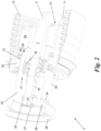
Fig. 2 einen der Anschlussstutzen der Verbindungsleitung vonFig. 1 in einem perspektivischen Längsschnitt vergrößert im Detail. -
Fig. 1 zeigt eine Verbindungsleitung 1 für ein Kryofluid. Das Kryofluid kann beispielsweise Wasserstoff sein, der bei Temperaturen von etwa -250 °C und einem Druck von bis zu 16 bar - oder mehr, je nach Behälterbauart - zumindest teilweise verflüssigt vorliegt, oder ein vergleichbares, in Verbrennungskraftmaschinen oder Brennstoffzellen einsetzbares Kryofluid, z.B. verflüssigtes Erdgas (liquefied natural gas, LNG) mit einer Temperatur von etwa -161 °C. Das Kryofluid kann aber auch ein Kältemittel sein, beispielsweise Flüssigstickstoff, mit dem das Kühlsystem von Kühllastern betrieben wird, z.B. von Lebensmitteltransportern. - Die Verbindungsleitung 1 hat an ihren beiden Enden jeweils einen Anschlussstutzen 2, 3, mit dem sie dort an eine anzuschließende Komponente, z.B. einen Kraftstofftank, einen Kältemittelbehälter oder eine Armatur zum Befüllen oder Entnehmen von Kryofluid daraus, angeschlossen werden kann. Beispielsweise dient die Verbindungsleitung 1 zum Verbinden zweier an den gegenüberliegenden Seiten eines Lastkraftwagens (LKWs) montierten Wasserstofftanks, um diese gemeinsam von einer Fahrzeugseite her befüllen oder entleeren zu können.
- Die Verbindungsleitung 1 wird dabei von den über die Anschlussstutzen 2, 3 angeschlossenen Komponenten mitgetragen. Alternativ oder zusätzlich hat sie an ihrer Außenseite eine Verankerung 4, über welche sie z.B. an einem Fahrzeugchassis befestigt werden kann. Die Verbindungsleitung 1 ist dadurch entweder an zwei Verankerungspunkten, nämlich den angeschlossenen Komponenten, die am Fahrzeugchassis montiert sind, oder an drei Verankerungspunkte, nämlich den beiden angeschlossenen Komponenten und der Verankerung 4, am Fahrzeugchassis fixiert.
- Die Verbindungsleitung 1 ist eine evakuierbare Doppelwandkonstruktion aufgebaut aus einer inneren Kryoleitung in Form eines flexiblen Schlauchs 5 und einem diesen mit Umfangsspiel umgebenden starren Rohr 6. Die Enden 7, 8 des Schlauchs 5 sind mit den Enden 9, 10 des Rohrs 6 über jeweils einen der Anschlussstutzen 2, 3 dicht verbunden. Dadurch ist der Spiel- bzw. Zwischenraum 11 zwischen Schlauch 5 und Rohr 6 zwecks thermischer Isolierung des Schlauchs 5 evakuierbar, z.B. über eine verschließbare Evakuierungsöffnung 12 des Rohrs 6.
- Zumindest eine der dichten Verbindungen zwischen dem jeweiligen Rohrende 9, 10 und dem jeweiligen Anschlussstutzen 2, 3, hier beide dichte Verbindungen, erfolgt über eine Faltenbalgmanschette 13, 14. Das dem Anschlussstutzen 2 abgewandte Ende 15 der Faltenbalgmanschette 13 ist mit dem Rohrende 9 verbunden, und das dem Anschlussstutzen 3 abgewandte Ende 16 der Faltenbalgmanschette 14 ist mit dem Rohrende 10 verbunden. Wenn nur eine Faltenbalgmanschette z.B. zwischen dem Anschlussstutzen 2 und dem Rohrende 9 verwendet wird, kann das andere Rohrende 10 direkt mit dem anderen Anschlussstutzen 3 dicht verbunden sein.
- Das Rohr 6 und die Faltenbalgmanschetten 13, 14 können z.B. aus Kunststoff gefertigt sein. Für Tiefsttemperaturfestigkeit werden sie aus Metall gefertigt, beispielsweise aus Edelstahl oder Aluminium. Die Faltenbalgmanschetten 13, 14 haben dadurch eine federnde Ruhestellung zwischen ihrer auseinandergezogenen und ihrer zusammengezogenen Stellung.
- Die Längen des Schlauchs 5, des Rohres 6 und der Faltenbalgmanschetten 13, 14 sind so dimensioniert, dass in einer stärker auseinandergezogenen Stellung einer oder beider Faltenbalgmanschetten 13, 14 der Schlauch 5 weniger stark gekrümmt ist, beispielsweise gestreckt, und in einer zusammengezogenen Stellung einer oder beider Faltenbalgmanschetten 13, 14 der Schlauch 5 stärker gekrümmt ist. Beispielsweise zeigt
Fig. 1 die Ruhestellung der Faltenbalgmanschetten 13, 14, in welcher der Schlauch 5 mehrfach gekrümmt durch das Rohr 6 verläuft. Beim Auseinanderziehen einer oder beider Faltenbalgmanschetten 13, 14 kann sich der Schlauch 5 strecken und beim Zusammenziehen einer oder beider Faltenbalgmanschetten 13, 14 stärker krümmen. - Dadurch können Relativbewegungen zwischen den durch die Verbindungsleitung 1 verbundenen Komponenten aufgenommen werden. Wenn die Verankerung 4 als dritter Verankerungspunkt verwendet wird, können die eine Faltenbalgmanschette 13 und der gekrümmte Schlauch 5 Relativbewegungen zwischen der Verankerung 4 und der einen Komponente und die andere Faltenbalgmanschette 14 und der gekrümmte Schlauch 5 Relativbewegungen zwischen der Verankerung 4 und der anderen Komponente ausgleichen.
- Der Schlauch 5 ist aus einem flexiblen Material gefertigt, beispielsweise Kunststoff oder biegsamem Metall. Als Scheuerschutz gegenüber der Innenseite des Rohres 6 bei einer zu starken Krümmung des Schlauches 5 ist der Schlauch 5 optional mit einem scheuerfestem Mantel 17 versehen. Der Mantel 17 kann beispielsweise aus einem Gewebe, Gelege, Gewirke oder Vlies von Glasfasern gefertigt sein. Zwischen Schlauch 5 und Mantel 17 ist optional eine Schicht 18 aus einem thermisch isolierenden Material zwischengelegt. Beispielsweise ist die Schicht 18 durch eine wärmestrahlungsisolierende Aluminiumfolie gebildet, die in mehreren Lagen rund um den Schlauch 5 gewickelt wird, wobei ein wärmeleitungsisolierendes Vlies zwischen den Lagen mitgewickelt wird.
- Der Aufbau eines der Anschlussstutzen 2, 3 wird nun anhand von
Fig. 2 für den Anschlussstutzen 2 im Detail erläutert. Der Aufbau des Anschlussstutzens 3 ist analog. - Gemäß
Fig. 2 umfasst der Anschlussstutzen 2 einen mit dem Schlauchende 7 verbindbaren Innenstutzen 19 sowie einen direkt oder über den Faltenbalgabschnitt 13, falls vorhanden, mit dem Rohrende 9 verbindbaren Außenstutzen 20. Innen- und Außenstutzen 19, 20 sind über eine Ringstruktur 21 miteinander verbunden. Die Ringstruktur 21 kann eine dichte Verbindung zwischen Innenstutzen 19 und Außenstutzen 20 errichten, wodurch der Zwischenraum 11 gesondert wärmeisolierbar, insbesondere evakuierbar ist. Alternativ kann die Ringstruktur 21 gasdurchlässig sein, so dass der Zwischenraum 11 mit dem Ringraum 22 zwischen Innenstutzen 19 und Außenstutzen 20 druckverbunden und mit diesem gemeinsam evakuierbar ist, falls gewünscht. - Die Ringstruktur 21 ist gegenüber den freien Enden 23, 24 von Innen- und Außenstutzen 19, 20 in Richtung auf das Rohr 6 hin zurückversetzt, so dass die Enden 23, 24 für die anzuschließenden Komponenten, z.B. einen Fahrzeugtank oder eine Armatur, frei zugänglich sind. Zu diesem Zweck haben die freien Enden 23, 24 von Innen- und Außenstutzen 19, 20 z.B. jeweils einen Endflansch 25, 26 mit einer Überwurfmutter 27, 28. Damit kann der Innenstutzen 19 z.B. mit einem Kryofluidanschluss und der Außenflansch 20 z.B. mit einem lastaufnehmenden Gewinde, das eine Evakuieröffnung zum Evakuieren des Ringraums 22 hat, verbunden werden.
- Um das Herstellen dieser Verbindungen, insbesondere der Verschraubungen mittels der Überwurfmuttern 27, 28, zu erleichtern, kann die Ringstruktur 21 mit dem Außenstutzen 20 optional über eine axialbewegliche Kupplung 29 verbunden sein. Die Kupplung 29 erlaubt eine Ein- und Auswärtsbewegung des Außenstutzens 20 gegenüber der Ringstruktur 21 und dem damit verbundenen Innenstutzen 19, z.B. zum Zurückschieben des Außenstutzens 20 zum Freilegen des Endes 23 des Innenstutzens 19, um den Innenstutzen 19 mit einem Kryofluidanschluss mittels der Überwurfmutter 27 zu verschrauben. Anschließend wird der Außenstutzen 20 wieder vorgeschoben, um den Außenstutzen 20 mittels der Überwurfmutter 28 an der anzuschließenden Komponente zu fixieren.
- Die Kupplung 29 umfasst einen Anschlag, der die Auswärtsbewegung des Außenstutzens 20 begrenzt. Dazu hat einer der Teile Außenstutzen 20 und Ringstruktur 21 (hier: die Ringstruktur 21) einen Innenabsatz 30 und der andere der Teile Außenstutzen 20 und Ringstruktur 21 (hier: der Außenstutzen 20) einen daran bei der Auswärtsbewegung des Außenstutzens 20 anschlagenden Außenabsatz 31.
- Die Kupplung 29 kann drehbar oder drehfest ausgebildet sein. Bei einer drehfesten Kupplung 29 kann die Rotationslage der Drehfixierung einstellbar sein. Zur Einstellung kann beispielsweise der Außenstutzen 20 einen Außenzahnkranz 32 und die Ringstruktur 21 einen Innenzahnkranz 33 haben (oder umgekehrt), welche Zahnkränze ineinander eingreifen können und so die Drehfixierung der Kupplung 22 erreichen. Durch Einwärtsbewegen des Außenstutzens 20 können die Zahnkränze 32, 33 außer Eingriff gebracht und dann der Außenstutzen 20 gegenüber der Ringstruktur 21 verdreht werden, um eine andere Drehfixierungslage auszuwählen, in der der Außenstutzen 20 beim Auswärtsbewegen wieder drehfest einrastet. Die Ringstruktur 21 kann dazu eine ringförmige Vertiefung 34 haben, in welche der Außenstutzen 20 bei seiner Einwärtsbewegung eintauchen kann.
- Wie in
Fig. 2 gezeigt, kann die Ringstruktur 21 optional einen Faltenbalgabschnitt 35 haben, um Relativbewegungen zwischen dem Innenstutzen 19 und dem Außenstutzen 20, insbesondere Verkippungen oder Offsets zwischen ihren Längsachsen, auszugleichen. Dies kann nützlich sein, um Toleranzen zwischen einem Kryofluidanschluss, mit dem der Innenstutzen 19 verbunden ist, und einem Evakuier- und Lastanschluss, mit dem der Außenstutzen 20 verbunden ist, oder um allfällige Biegebewegungen des Innenstutzens 19 mit dem Schlauch 5, wenn er sich bewegt, zu kompensieren. - Der in die Ringstruktur 21 integrierte Faltenbalgabschnitt 35 kann beispielsweise - so wie im Übrigen auch die Faltenbalgmanschetten 13, 14 - eine Einhüllende haben, die etwa zylinderförmig ist und koaxial und mit Radialabständen sowohl zum Innenstutzen 19 als auch zum Außenstutzen 20 verläuft.
- Die ringförmige Vertiefung 34 der Ringstruktur 21 liegt im gezeigten Beispiel zwischen dem Faltenbalgabschnitt 35 und der Kupplung 29. Der Faltenbalgabschnitt 35 könnte jedoch an anderer Stelle der Ringstruktur 21 liegen, z.B. in der Art einer zickzack gefalteten Ringscheibe.
- Im Rohr 6, insbesondere entlang des Schlauches 5, kann ein Bindemittel 36 für Wasserstoffgas angeordnet werden. Das Bindemittel 36 kann beispielsweise in einem mit Gaseintritten versehenen Gitterkäfig 37 enthalten sein, der etwa stab- oder boltzenförmig neben dem Schlauch 5 im Rohr 6 über dessen gesamte Länge verläuft.
- Die Erfindung ist nicht auf die dargestellten Ausführungsformen beschränkt, sondern umfasst alle Varianten, Modifikationen und deren Kombinationen, die in den Rahmen der angeschlossenen Ansprüche fallen.
Claims (12)
- Verbindungsleitung für ein Kryofluid, mit einem flexiblen Schlauch, der an jedem Ende mit einem Anschlussstutzen versehen ist, dadurch gekennzeichnet, dass der Schlauch (5) mit Umfangsspiel in einem starren Rohr (6) liegt, dessen Enden (9, 10) mit je einem Anschlussstutzen (2, 3) dicht verbunden sind, sodass der Spielraum (11) zwischen Schlauch (5) und Rohr (6) evakuierbar ist, wobei zumindest eine der dichten Verbindungen zwischen Rohrende (9, 10) und Anschlussstutzen (2, 3) über eine Faltenbalgmanschette (13, 14) erfolgt, in deren auseinandergezogener Stellung der Schlauch (5) weniger gekrümmt und in deren zusammengezogener Stellung der Schlauch (5) mehr gekrümmt ist.
- Verbindungsleitung nach Anspruch 1, dadurch gekennzeichnet, dass jede der beiden dichten Verbindungen über je eine Faltenbalgmanschette (13, 14) erfolgt.
- Verbindungsleitung nach Anspruch 1 oder 2, dadurch gekennzeichnet, dass die zumindest eine Faltenbalgmanschette (13, 14) aus Metall gefertigt ist, bevorzugt aus Edelstahl.
- Verbindungsleitung nach einem der Ansprüche 1 bis 3, dadurch gekennzeichnet, dass der Schlauch (5) mit einem scheuerfesten Mantel (17) versehen ist, bevorzugt aus Glasfaser.
- Verbindungsleitung nach Anspruch 4, dadurch gekennzeichnet, dass zwischen Schlauch (5) und Mantel (17) eine Schicht (18) aus thermisch isolierendem Material zwischengelegt ist.
- Verbindungsleitung nach Anspruch 5, dadurch gekennzeichnet, dass die Schicht (18) aus einer mehrlagigen Aluminiumfolie mit einem wärmeleitungsisolierenden Vlies zwischen den Lagen gebildet ist.
- Verbindungsleitung nach einem der Ansprüche 1 bis 6, dadurch gekennzeichnet, dass in dem Rohr (6) ein Bindemittel (36) für Wasserstoffgas angeordnet ist.
- Verbindungsleitung nach Anspruch 7, dadurch gekennzeichnet, dass das Bindemittel (36) in einem mit Gaseintritten versehenen Gitterkäfig (37) enthalten ist, der neben dem Schlauch (5) im Rohr (6) verläuft.
- Verbindungsleitung nach einem der Ansprüche 1 bis 8, dadurch gekennzeichnet, dass das Rohr (6) aus Metall gefertigt ist, bevorzugt aus Aluminium.
- Verbindungsleitung nach einem der Ansprüche 1 bis 9, dadurch gekennzeichnet, dass das Rohr (6) an seiner Außenseite mit einer Verankerung (4) zur Montage an einem Fahrzeugchassis ausgestattet ist.
- Verbindungsleitung nach einem der Ansprüche 1 bis 10, dadurch gekennzeichnet, dass jeder Anschlussstutzen (2, 3) einen Innenstutzen (19) und einen diesen mit Abstand umgebenden Außenstutzen (20) umfasst, wobei der Innenstutzen (19) mit dem Schlauchende (7, 8) und der Außenstutzen (20) mit dem Rohrende (9, 10) oder dessen Faltenbalgmanschette (13, 14), falls vorhanden, verbunden ist, und wobei Innen- und Außenstutzen (19, 20) über eine gegenüber ihren freien Enden (23, 24) zurückversetzte Ringstruktur (22) dicht miteinander verbunden sind.
- Verbindungsleitung nach Anspruch 11, dadurch gekennzeichnet, dass die Ringstruktur (22) einen Faltenbalgabschnitt (35) enthält.
Priority Applications (1)
| Application Number | Priority Date | Filing Date | Title |
|---|---|---|---|
| EP23181673.7A EP4484814B1 (de) | 2023-06-27 | 2023-06-27 | Verbindungsleitung für ein kryofluid |
Applications Claiming Priority (1)
| Application Number | Priority Date | Filing Date | Title |
|---|---|---|---|
| EP23181673.7A EP4484814B1 (de) | 2023-06-27 | 2023-06-27 | Verbindungsleitung für ein kryofluid |
Publications (3)
| Publication Number | Publication Date |
|---|---|
| EP4484814A1 true EP4484814A1 (de) | 2025-01-01 |
| EP4484814B1 EP4484814B1 (de) | 2026-03-11 |
| EP4484814C0 EP4484814C0 (de) | 2026-03-11 |
Family
ID=87003287
Family Applications (1)
| Application Number | Title | Priority Date | Filing Date |
|---|---|---|---|
| EP23181673.7A Active EP4484814B1 (de) | 2023-06-27 | 2023-06-27 | Verbindungsleitung für ein kryofluid |
Country Status (1)
| Country | Link |
|---|---|
| EP (1) | EP4484814B1 (de) |
Citations (4)
| Publication number | Priority date | Publication date | Assignee | Title |
|---|---|---|---|---|
| US3068026A (en) * | 1958-06-13 | 1962-12-11 | Gen Motors Corp | Cryogenic fluid transfer line coupling |
| US6094922A (en) * | 1998-09-09 | 2000-08-01 | Ziegler; Alex R. | Vacuum-insulated refrigerant line for allowing a vaccum chamber system with water-vapor cryocoil compressor to be locatable outside cleanroom |
| WO2008135780A1 (en) * | 2007-05-03 | 2008-11-13 | Verderg Ltd | Offloading pipeline |
| US20230139421A1 (en) * | 2021-10-28 | 2023-05-04 | Airbus Sas | Optimized connection assembly between two portions of a supply line for a cryogenic fluid, including an additional thermal insulation chamber and a fluid expansion chamber |
-
2023
- 2023-06-27 EP EP23181673.7A patent/EP4484814B1/de active Active
Patent Citations (4)
| Publication number | Priority date | Publication date | Assignee | Title |
|---|---|---|---|---|
| US3068026A (en) * | 1958-06-13 | 1962-12-11 | Gen Motors Corp | Cryogenic fluid transfer line coupling |
| US6094922A (en) * | 1998-09-09 | 2000-08-01 | Ziegler; Alex R. | Vacuum-insulated refrigerant line for allowing a vaccum chamber system with water-vapor cryocoil compressor to be locatable outside cleanroom |
| WO2008135780A1 (en) * | 2007-05-03 | 2008-11-13 | Verderg Ltd | Offloading pipeline |
| US20230139421A1 (en) * | 2021-10-28 | 2023-05-04 | Airbus Sas | Optimized connection assembly between two portions of a supply line for a cryogenic fluid, including an additional thermal insulation chamber and a fluid expansion chamber |
Also Published As
| Publication number | Publication date |
|---|---|
| EP4484814B1 (de) | 2026-03-11 |
| EP4484814C0 (de) | 2026-03-11 |
Similar Documents
| Publication | Publication Date | Title |
|---|---|---|
| EP3258562B1 (de) | Verfahren zum aufbau einer übertragungsstrecke für elektrische energie | |
| DE102014206370A1 (de) | Druckbehälter mit einem Innen- und einem Außenbehälter | |
| DE102016201477A1 (de) | Druckbehälter sowie Verfahren zur Herstellung eines Druckbehälters | |
| DE60222920T2 (de) | Buchse für pulsationsrohrkühlvorrichtung | |
| EP2541560A1 (de) | Supraleiterkabel | |
| DE102015204623A1 (de) | Kryogener Druckbehälter und Verfahren zum Montieren eines kryogenen Druckbehälters | |
| DE102020128607A1 (de) | Verfahren zur Herstellung einer Brennstoffleiste für ein Druckbehältersystem, Brennstoffleiste, Druckbehältersystem und Kraftfahrzeug | |
| WO2013107547A1 (de) | Speicherbehälter von kryogenem druckgas mit einem einlass | |
| EP4235001B1 (de) | Thermisch isolierte transferleitung mit kuppelelement | |
| EP1571390B1 (de) | Doppelwandiger Behälter mit magnetischer Aufhängung | |
| EP4484814B1 (de) | Verbindungsleitung für ein kryofluid | |
| EP4484815A1 (de) | Anschlussstutzen für eine kryoleitung | |
| EP4013990B1 (de) | Kryobehälter mit rohrdurchführungsmodul | |
| DE4041170C1 (en) | Double-walled insulated container - incorporates metal woven band with shield made of aluminium | |
| DE102006024122B4 (de) | Vorrichtung zur Verbindung zweier Sammelrohre bei Kollektoren für Solaranlagen | |
| DE1116247B (de) | Rohrelement fuer Waermeaustauscher, bei dem ein Mantel ein Kernrohr und mindestens ein an dessen Umfang anliegendes Aussenrohr kleineren Querschnittes umschliesst | |
| EP0281685B1 (de) | Als Kompensator wirkender, rohrförmiger Faltenbalg | |
| EP1457729B1 (de) | Abstandshalter für ein langgestrecktes Substrat | |
| EP1927803B1 (de) | Flexibles Leitungselement für innendruckbeaufschlagte Leitungen | |
| DE102005035647B4 (de) | Kryotank mit Kühlschild | |
| EP1131580B1 (de) | Rohrförmige konstruktion | |
| DE102010027570B3 (de) | Faltenbalg-Kompensator | |
| EP1322888B1 (de) | Rohrartige leitung oder behälter zum transport bzw. zum aufbewahren kryogener medien und verfahren zur herstellung | |
| EP0708907B1 (de) | Wärmespeicher, insbesondere latentwärmespeicher | |
| EP4235002A1 (de) | Thermisch isolierte transferleitung |
Legal Events
| Date | Code | Title | Description |
|---|---|---|---|
| PUAI | Public reference made under article 153(3) epc to a published international application that has entered the european phase |
Free format text: ORIGINAL CODE: 0009012 |
|
| STAA | Information on the status of an ep patent application or granted ep patent |
Free format text: STATUS: THE APPLICATION HAS BEEN PUBLISHED |
|
| AK | Designated contracting states |
Kind code of ref document: A1 Designated state(s): AL AT BE BG CH CY CZ DE DK EE ES FI FR GB GR HR HU IE IS IT LI LT LU LV MC ME MK MT NL NO PL PT RO RS SE SI SK SM TR |
|
| STAA | Information on the status of an ep patent application or granted ep patent |
Free format text: STATUS: REQUEST FOR EXAMINATION WAS MADE |
|
| 17P | Request for examination filed |
Effective date: 20250618 |
|
| GRAP | Despatch of communication of intention to grant a patent |
Free format text: ORIGINAL CODE: EPIDOSNIGR1 |
|
| STAA | Information on the status of an ep patent application or granted ep patent |
Free format text: STATUS: GRANT OF PATENT IS INTENDED |
|
| RIC1 | Information provided on ipc code assigned before grant |
Ipc: F16L 27/11 20060101AFI20251002BHEP Ipc: F16L 27/12 20060101ALI20251002BHEP Ipc: F16L 39/00 20060101ALI20251002BHEP Ipc: F16L 59/065 20060101ALI20251002BHEP Ipc: F16L 59/14 20060101ALI20251002BHEP Ipc: F16L 59/18 20060101ALI20251002BHEP Ipc: F16L 51/02 20060101ALI20251002BHEP Ipc: F16L 51/04 20060101ALI20251002BHEP Ipc: F17C 13/00 20060101ALN20251002BHEP |
|
| RIC1 | Information provided on ipc code assigned before grant |
Ipc: F16L 27/11 20060101AFI20251009BHEP Ipc: F16L 27/12 20060101ALI20251009BHEP Ipc: F16L 39/00 20060101ALI20251009BHEP Ipc: F16L 59/065 20060101ALI20251009BHEP Ipc: F16L 59/14 20060101ALI20251009BHEP Ipc: F16L 59/18 20060101ALI20251009BHEP Ipc: F16L 51/02 20060101ALI20251009BHEP Ipc: F16L 51/04 20060101ALI20251009BHEP Ipc: F17C 13/00 20060101ALN20251009BHEP |
|
| INTG | Intention to grant announced |
Effective date: 20251016 |
|
| RIC1 | Information provided on ipc code assigned before grant |
Ipc: F16L 27/11 20060101AFI20251010BHEP Ipc: F16L 27/12 20060101ALI20251010BHEP Ipc: F16L 39/00 20060101ALI20251010BHEP Ipc: F16L 59/065 20060101ALI20251010BHEP Ipc: F16L 59/14 20060101ALI20251010BHEP Ipc: F16L 59/18 20060101ALI20251010BHEP Ipc: F16L 51/02 20060101ALI20251010BHEP Ipc: F16L 51/04 20060101ALI20251010BHEP Ipc: F17C 13/00 20060101ALN20251010BHEP |
|
| GRAS | Grant fee paid |
Free format text: ORIGINAL CODE: EPIDOSNIGR3 |
|
| GRAA | (expected) grant |
Free format text: ORIGINAL CODE: 0009210 |
|
| STAA | Information on the status of an ep patent application or granted ep patent |
Free format text: STATUS: THE PATENT HAS BEEN GRANTED |
|
| AK | Designated contracting states |
Kind code of ref document: B1 Designated state(s): AL AT BE BG CH CY CZ DE DK EE ES FI FR GB GR HR HU IE IS IT LI LT LU LV MC ME MK MT NL NO PL PT RO RS SE SI SK SM TR |
|
| REG | Reference to a national code |
Ref country code: CH Ref legal event code: F10 Free format text: ST27 STATUS EVENT CODE: U-0-0-F10-F00 (AS PROVIDED BY THE NATIONAL OFFICE) Effective date: 20260311 Ref country code: GB Ref legal event code: FG4D Free format text: NOT ENGLISH |
|
| REG | Reference to a national code |
Ref country code: IE Ref legal event code: FG4D Free format text: LANGUAGE OF EP DOCUMENT: GERMAN |
|
| U01 | Request for unitary effect filed |
Effective date: 20260316 |
|
| U07 | Unitary effect registered |
Designated state(s): AT BE BG DE DK EE FI FR IT LT LU LV MT NL PT RO SE SI Effective date: 20260320 |