EP4484807A1 - Pendulum valve - Google Patents
Pendulum valve Download PDFInfo
- Publication number
- EP4484807A1 EP4484807A1 EP24171548.1A EP24171548A EP4484807A1 EP 4484807 A1 EP4484807 A1 EP 4484807A1 EP 24171548 A EP24171548 A EP 24171548A EP 4484807 A1 EP4484807 A1 EP 4484807A1
- Authority
- EP
- European Patent Office
- Prior art keywords
- gate
- traveler
- housing
- valve
- flap
- Prior art date
- Legal status (The legal status is an assumption and is not a legal conclusion. Google has not performed a legal analysis and makes no representation as to the accuracy of the status listed.)
- Pending
Links
Images



Classifications
-
- F—MECHANICAL ENGINEERING; LIGHTING; HEATING; WEAPONS; BLASTING
- F16—ENGINEERING ELEMENTS AND UNITS; GENERAL MEASURES FOR PRODUCING AND MAINTAINING EFFECTIVE FUNCTIONING OF MACHINES OR INSTALLATIONS; THERMAL INSULATION IN GENERAL
- F16K—VALVES; TAPS; COCKS; ACTUATING-FLOATS; DEVICES FOR VENTING OR AERATING
- F16K3/00—Gate valves or sliding valves, i.e. cut-off apparatus with closing members having a sliding movement along the seat for opening and closing
- F16K3/02—Gate valves or sliding valves, i.e. cut-off apparatus with closing members having a sliding movement along the seat for opening and closing with flat sealing faces; Packings therefor
- F16K3/04—Gate valves or sliding valves, i.e. cut-off apparatus with closing members having a sliding movement along the seat for opening and closing with flat sealing faces; Packings therefor with pivoted closure members
- F16K3/10—Gate valves or sliding valves, i.e. cut-off apparatus with closing members having a sliding movement along the seat for opening and closing with flat sealing faces; Packings therefor with pivoted closure members with special arrangements for separating the sealing faces or for pressing them together
-
- F—MECHANICAL ENGINEERING; LIGHTING; HEATING; WEAPONS; BLASTING
- F16—ENGINEERING ELEMENTS AND UNITS; GENERAL MEASURES FOR PRODUCING AND MAINTAINING EFFECTIVE FUNCTIONING OF MACHINES OR INSTALLATIONS; THERMAL INSULATION IN GENERAL
- F16K—VALVES; TAPS; COCKS; ACTUATING-FLOATS; DEVICES FOR VENTING OR AERATING
- F16K3/00—Gate valves or sliding valves, i.e. cut-off apparatus with closing members having a sliding movement along the seat for opening and closing
- F16K3/02—Gate valves or sliding valves, i.e. cut-off apparatus with closing members having a sliding movement along the seat for opening and closing with flat sealing faces; Packings therefor
- F16K3/04—Gate valves or sliding valves, i.e. cut-off apparatus with closing members having a sliding movement along the seat for opening and closing with flat sealing faces; Packings therefor with pivoted closure members
- F16K3/06—Gate valves or sliding valves, i.e. cut-off apparatus with closing members having a sliding movement along the seat for opening and closing with flat sealing faces; Packings therefor with pivoted closure members in the form of closure plates arranged between supply and discharge passages
-
- F—MECHANICAL ENGINEERING; LIGHTING; HEATING; WEAPONS; BLASTING
- F16—ENGINEERING ELEMENTS AND UNITS; GENERAL MEASURES FOR PRODUCING AND MAINTAINING EFFECTIVE FUNCTIONING OF MACHINES OR INSTALLATIONS; THERMAL INSULATION IN GENERAL
- F16K—VALVES; TAPS; COCKS; ACTUATING-FLOATS; DEVICES FOR VENTING OR AERATING
- F16K3/00—Gate valves or sliding valves, i.e. cut-off apparatus with closing members having a sliding movement along the seat for opening and closing
- F16K3/02—Gate valves or sliding valves, i.e. cut-off apparatus with closing members having a sliding movement along the seat for opening and closing with flat sealing faces; Packings therefor
- F16K3/0227—Packings
-
- F—MECHANICAL ENGINEERING; LIGHTING; HEATING; WEAPONS; BLASTING
- F16—ENGINEERING ELEMENTS AND UNITS; GENERAL MEASURES FOR PRODUCING AND MAINTAINING EFFECTIVE FUNCTIONING OF MACHINES OR INSTALLATIONS; THERMAL INSULATION IN GENERAL
- F16K—VALVES; TAPS; COCKS; ACTUATING-FLOATS; DEVICES FOR VENTING OR AERATING
- F16K3/00—Gate valves or sliding valves, i.e. cut-off apparatus with closing members having a sliding movement along the seat for opening and closing
- F16K3/02—Gate valves or sliding valves, i.e. cut-off apparatus with closing members having a sliding movement along the seat for opening and closing with flat sealing faces; Packings therefor
- F16K3/0254—Gate valves or sliding valves, i.e. cut-off apparatus with closing members having a sliding movement along the seat for opening and closing with flat sealing faces; Packings therefor being operated by particular means
-
- F—MECHANICAL ENGINEERING; LIGHTING; HEATING; WEAPONS; BLASTING
- F16—ENGINEERING ELEMENTS AND UNITS; GENERAL MEASURES FOR PRODUCING AND MAINTAINING EFFECTIVE FUNCTIONING OF MACHINES OR INSTALLATIONS; THERMAL INSULATION IN GENERAL
- F16K—VALVES; TAPS; COCKS; ACTUATING-FLOATS; DEVICES FOR VENTING OR AERATING
- F16K3/00—Gate valves or sliding valves, i.e. cut-off apparatus with closing members having a sliding movement along the seat for opening and closing
- F16K3/30—Details
- F16K3/314—Forms or constructions of slides; Attachment of the slide to the spindle
-
- F—MECHANICAL ENGINEERING; LIGHTING; HEATING; WEAPONS; BLASTING
- F16—ENGINEERING ELEMENTS AND UNITS; GENERAL MEASURES FOR PRODUCING AND MAINTAINING EFFECTIVE FUNCTIONING OF MACHINES OR INSTALLATIONS; THERMAL INSULATION IN GENERAL
- F16K—VALVES; TAPS; COCKS; ACTUATING-FLOATS; DEVICES FOR VENTING OR AERATING
- F16K3/00—Gate valves or sliding valves, i.e. cut-off apparatus with closing members having a sliding movement along the seat for opening and closing
- F16K3/30—Details
- F16K3/316—Guiding of the slide
-
- F—MECHANICAL ENGINEERING; LIGHTING; HEATING; WEAPONS; BLASTING
- F16—ENGINEERING ELEMENTS AND UNITS; GENERAL MEASURES FOR PRODUCING AND MAINTAINING EFFECTIVE FUNCTIONING OF MACHINES OR INSTALLATIONS; THERMAL INSULATION IN GENERAL
- F16K—VALVES; TAPS; COCKS; ACTUATING-FLOATS; DEVICES FOR VENTING OR AERATING
- F16K31/00—Actuating devices; Operating means; Releasing devices
- F16K31/44—Mechanical actuating means
- F16K31/60—Handles
- F16K31/602—Pivoting levers, e.g. single-sided
-
- F—MECHANICAL ENGINEERING; LIGHTING; HEATING; WEAPONS; BLASTING
- F16—ENGINEERING ELEMENTS AND UNITS; GENERAL MEASURES FOR PRODUCING AND MAINTAINING EFFECTIVE FUNCTIONING OF MACHINES OR INSTALLATIONS; THERMAL INSULATION IN GENERAL
- F16K—VALVES; TAPS; COCKS; ACTUATING-FLOATS; DEVICES FOR VENTING OR AERATING
- F16K39/00—Devices for relieving the pressure on the sealing faces
- F16K39/04—Devices for relieving the pressure on the sealing faces for sliding valves
- F16K39/045—Devices for relieving the pressure on the sealing faces for sliding valves of rotating or pivoting type
-
- G—PHYSICS
- G01—MEASURING; TESTING
- G01N—INVESTIGATING OR ANALYSING MATERIALS BY DETERMINING THEIR CHEMICAL OR PHYSICAL PROPERTIES
- G01N30/00—Investigating or analysing materials by separation into components using adsorption, absorption or similar phenomena or using ion-exchange, e.g. chromatography or field flow fractionation
- G01N30/02—Column chromatography
- G01N30/04—Preparation or injection of sample to be analysed
- G01N30/16—Injection
- G01N30/20—Injection using a sampling valve
- G01N2030/202—Injection using a sampling valve rotary valves
Definitions
- This disclosure relates generally to a valve and, more particularly, to a pendulum valve.
- GCMS gas-chromatography-mass-spectrometry systems
- LCMS liquid-chromatography-mass-spectrometry systems
- Analytical instruments may include a valve to temporarily isolate, or allow passage of material to, one volume from another.
- the material can flow through an opening in the valve.
- the valves can include a seal surrounding the opening and a surface that engages and disengages the seal as the valve opens and closes. Contaminants can enter the analytical instrument if the valve seal breaks down.
- valves such as ball valves with polytetrafluoroethylene (PTFE) seats
- PTFE polytetrafluoroethylene
- Such valves can use harder seal materials, such as plastics, to withstand these shear forces.
- harder seal materials can be subject to wear over time which can lead to bits of the seal material breaking off and entering the analytical instrument through the valve.
- These valves are also not well suited for compact applications due to the relationship between the size of the ball component and the size of the valve passage needed for an application.
- valve types such as gate or pendulum valves
- softer seal materials are not ideally suited for shear forces.
- the gate or pendulum valves are therefore designed to avoid shear forces on the seal. These valves can first move the seal over the opening before moving the seal closed.
- Some gate or pendulum valves incorporate a cam, a second motor, mechanical linkage, or pneumatic action to press the seal closed after it has been moved into place.
- these designs can require multiple actuation motions or may require parts that can be more costly or complicated to manufacture. Therefore, an improved valve that is durable with compact form, reduced complexity and part count, and reduced entrainment of particulates is desired.
- a valve can include a housing, a gate, and a traveler.
- the housing can include a first side and a second side opposite the first side.
- the housing can include an opening such that material can pass through the opening from the first side to the second side.
- the gate can be disposed within a cavity defined by the housing.
- the gate can be moveable relative to the housing in a first direction between a first gate position and a second gate position. At least a portion of the gate can be moveable relative to the housing in a second direction between the second gate position and a third gate position.
- the second direction can be different from the first direction.
- the gate can allow material flow through the opening in the first gate position and preventing material flow through the opening in the third gate position.
- the traveler can be disposed within the cavity.
- the traveler can be moveable from a first traveler position to a second traveler position.
- the traveler can be configured to move the gate in the first and second directions as the traveler moves from the first traveler position to the second traveler position.
- the traveler can include an abutment surface to apply a force to an inclined surface of the gate to move the portion of the gate between the second gate position and the third gate position.
- the gate can rotate about a gate axis as the gate moves in the first direction.
- the portion of the gate can be a gate flap coupled with a gate body and angularly displaceable relative to the gate body from a first gate flap position to a second gate flap position as the gate flap moves in the second direction.
- At least one of the housing and the gate can include a seal cavity and the valve can include a seal disposed at least partially within the seal cavity, the seal engaged with the housing and the gate when the gate is in the third gate position such that the seal is disposed around at least a portion of the opening.
- the seal can be disengaged from at least one of the gate and the housing as the gate moves from the first gate position to the second gate position.
- the traveler can rotate about a traveler axis as the traveler moves from the first traveler position to the second traveler position.
- the gate body can include a first end and a second end spaced from the first end in a lateral direction.
- the gate flap can extend from the gate body toward the traveler in a longitudinal direction different from the lateral direction so as to define a first angle between the gate body and the gate flap.
- the abutment surface of the traveler can engage the gate flap such that the gate is fixed relative to the traveler as the gate moves from the first gate position to the second gate position.
- the valve includes a shaft and a seal disposed about the shaft, the seal configured to permit purging the cavity.
- the gate can move linearly as the gate moves from the second gate position to the third gate position.
- the abutment surface can apply a force to the gate flap in a force direction different from the first direction such that the gate flap moves between the second gate position and the third gate position so as to define a second angle between the gate flap and the gate body, the second angle different from the first angle.
- the valve includes a shaft and an actuator rotationally fixed to the shaft.
- the gate can include a gate shaft opening and the shaft is disposed in the gate shaft opening such that the gate is rotatable relative to the shaft.
- the traveler can include a traveler shaft opening defined by a sidewall with the shaft disposed in the traveler shaft opening, at least one of the shaft and the sidewall including a protrusion and the other of the shaft and the sidewall including a recess to receive the protrusion such that the traveler is rotationally fixed to the shaft. Rotation of the actuator can rotate the traveler.
- the valve can include a secondary outlet configured to facilitate material movement into or from the cavity when the gate is in the third gate position.
- One of the gate and the housing can include an inclined surface and the other of the gate and the housing can include a contact surface such that the gate moves relative to the housing in a third direction different from the first direction in response to engagement of the contact surface and the inclined surface.
- An analytical instrument can include a housing, a shaft, a gate, a traveler, an apparatus, and an actuator.
- the housing can define a cavity and an opening in communication with the cavity such that material can pass through the opening into or out of the cavity.
- the shaft can be rotatable relative to the housing.
- the gate can be disposed within the cavity, the gate moveable relative to the housing between a sealed position and an unsealed position, the gate allowing material passage through the opening in the unsealed position and preventing material passage through the opening in the sealed position.
- the traveler can be rotationally fixed to the shaft and disposed within the cavity, the traveler including a trailing end and a leading end spaced from the trailing end in a first direction, wherein the leading end engages an inclined surface of the gate as the traveler moves in the first direction from a first traveler position to a second traveler position so as to move the gate from the unsealed position to the sealed position.
- the apparatus can be configured to couple with the housing, the apparatus containing material such that material moves from the apparatus through the opening.
- the actuator can be rotationally fixed to the shaft such that the traveler moves from the first traveler position to the second traveler position in response to rotation of the actuator.
- the gate can be fixed relative to the traveler in the in the first direction as the gate moves from the unsealed position toward the sealed position.
- One of the gate and the housing can include a protrusion and the other of the gate and the housing can include a recess such that the position of the gate is fixed relative to the housing when the protrusion is within the recess.
- the traveler can move relative to each of the gate and the housing when the protrusion is within the recess.
- the gate can include a gate body and a gate flap rotatably coupled with the gate body such that the gate flap rotates relative to the gate body from a first gate flap position to a second gate flap position as the gate moves from the unsealed position to the sealed position.
- the gate can include an end wall transverse to the gate body and the trailing end of the traveler includes a trailing end abutment surface that engages the end wall so as to move the gate from the sealed position to the unsealed position as the traveler moves in a second direction opposite the first direction.
- the analytical instrument can include a secondary outlet in fluid communication with the cavity, the secondary outlet configured to purge the cavity when the gate is in the sealed position.
- Rotation of the actuator can couple the apparatus to the housing and moves the gate to the unsealed position.
- the gate can move in a first gate direction from the unsealed position to the sealed position.
- One of the housing and the gate include an inclined surface and the other of the housing and the gate include an engagement surface such that the gate moves relative to the housing in a longitudinal direction different from the first gate direction as the gate moves from the unsealed position to the sealed position.
- an aspect of the invention is defined by an analytical instrument comprising a housing defining a cavity and an opening in communication with the cavity such that material can pass through the opening into or out of the cavity; a shaft rotatable relative to the housing; a gate disposed within the cavity, the gate moveable relative to the housing between a sealed position and an unsealed position, the gate allowing material passage through the opening in the unsealed position and preventing material passage through the opening in the sealed position; a traveler rotationally fixed to the shaft and disposed within the cavity, the traveler including a trailing end and a leading end spaced from the trailing end in a first direction, wherein the leading end engages an inclined surface of the gate as the traveler moves in the first direction from a first traveler position to a second traveler position so as to move the gate from the unsealed position to the sealed position; an apparatus configured to couple with the housing, the apparatus containing material such that material moves from the apparatus through the opening; and an actuator rotationally fixed to the shaft such that the traveler
- the gate may be fixed relative to the traveler in the first direction as the gate moves from the unsealed position toward the sealed position.
- one of the gate and the housing may include a protrusion and the other of the gate and the housing may include a recess such that the position of the gate is fixed relative to the housing when the protrusion is within the recess.
- the traveler may move relative to each of the gate and the housing when the protrusion is within the recess.
- the gate may include a gate body and a gate flap rotatably coupled with the gate body such that the gate flap rotates relative to the gate body from a first gate flap position to a second gate flap position as the gate moves from the unsealed position to the sealed position.
- the gate includes an end wall transverse to the gate body and the trailing end of the traveler includes a trailing end abutment surface that engages the end wall so as to move the gate from the sealed position to the unsealed position as the traveler moves in a second direction opposite the first direction.
- the analytical instrument of the present invention may further comprise a secondary outlet in fluid communication with the cavity, the secondary outlet being configured to purge the cavity when the gate is in the sealed position.
- rotation of the actuator couples the apparatus to the housing and moves the gate to the unsealed position.
- the gate moves in a first gate direction from the unsealed position to the sealed position, and wherein one of the housing and the gate include an inclined surface and the other of the housing and the gate include an engagement surface such that the gate moves relative to the housing in a longitudinal direction different from the first gate direction as the gate moves from the unsealed position to the sealed position.
- An analytical instrument can include a valve that prevents material passage between internal and or external regions.
- the analytical instrument can be a mass spectrometer, gas-chromatography-mass-spectrometry system (GCMS), liquid- chromatography-mass-spectrometry system (LCMS), or other instrument that is configured to receive solid, powder, liquid and/or gas samples and to generate a characteristic signal describing one or more chemical, physical, and/or structural properties of the sample.
- the valve can isolate a first side from a second side when the valve is closed.
- the valve can be opened to allow material to transfer through an opening in a housing between the input and the output.
- the valve can include a gate that seals an opening in a sealed position and allows material passage in an unsealed position.
- a seal can be positioned about the opening such that the seal is sealingly engaged with the gate and the housing when the valve gate is in the sealed position. At least one of the gate and the housing disengage from the seal as the gate moves from the sealed position to the unsealed position.
- a valve that applies a shear force to the seal can result in excessive wear to the seal.
- the valve described herein can minimize or avoid any shear forces applied to the seal to prolong the useful life of the seal and reduce or eliminate entrainment of seal material through the cavity into the analytical instrument.
- the gate can be sequentially moveable in a first direction and a second direction different from the first direction so as to avoid excess wear on a seal when moving between the unsealed and sealed positions.
- the valve described herein can minimize or avoid any shear forces applied to the seal while having a compact form perpendicular to the valve opening and a low part count for economic construction.
- the valve described herein can employ a single actuation motion to move a gate over an opening and moving the gate into sealing engagement to close the valve.
- the valve described herein ensures correct placement and compression of the gate and a seal without requiring secondary actuators.
- valves can allow material to remain within the cavity after the valve is closed. That remaining material can pass through the opening when the valve is reopened. This can be undesirable when different materials are being introduced into the cavity during a subsequent use of the valve.
- the valve 100 described herein can be configured to purge material out of the cavity before use.
- the valve 100 can be purged to reduce pressure within the cavity.
- the pressure within the cavity can be equalized with the pressure within a component with which the valve 100 is coupled.
- the valve can include an actuator that moves the gate between the sealed and unsealed positions.
- the actuator also locks an apparatus or tool to a housing.
- the actuator can lock the apparatus to the housing and move the gate in a single motion.
- the actuator can lock the apparatus to the housing, activate the secondary outlet, and move the gate in a single motion.
- Existing valves can require a user to secure a sample container thereto and then open the valve after the securing step.
- the valve described herein can lock the apparatus to the housing and open the valve in a single step.
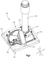
- the valve 100 can include a housing 102 having a first side 104 and a second side 106.
- the first side 104 can be opposite the second side 106 in a longitudinal direction L.
- the housing 102 can include first and second edges opposite each other in a lateral direction A.
- the lateral direction A can be perpendicular to the longitudinal direction L.
- the housing 102 can include first and second ends opposite each other in a transverse direction T.
- the transverse direction T can be perpendicular to each of the lateral and longitudinal directions A, L.
- the housing 102 can have a generally rectangular shape as shown in Fig. 1 . In other examples, the housing 102 can be circular, semi-circular, triangular, oval, or pentagonal.
- the housing 102 includes a first housing member 103 and a second housing member 105.
- the housing 102 is a monolithic construct.
- the first housing member 103 can be disposed on the first side 104 of the housing 102.
- the second housing member 105 can be disposed on the second side 106 of the housing 102.
- the first and second members 103, 105 can define an internal cavity. The cavity can be configured to receive elements of the valve 100.
- the valve 100 can include a sealing element to form a fluid tight seal between the first and second housing members 103, 105.
- the first housing member 103 can include a recess 113 configured to receive the sealing element.
- the second housing member 105 can include the recess 113.
- each of the first and second housing members 103, 105 can include the recess 113.
- the sealing element can be an o-ring, a gasket, a foam, a hardening (for example, epoxy) or non-hardening (for example, silicone) joining or sealing material, a compressed metal-to-metal interface, a weld, a braze, and or other common joining and sealing methods.
- an opening 108 can extend through the housing 102.
- the opening 108 can extend through the first housing member 103.
- the opening 108 can extend through the second housing member 105.
- the opening 108 has a circular shape in Fig. 2 .
- the opening 108 can have a triangular, rectangular, pentagonal, or other polygonal shape.
- the opening 108 can have an irregular shape.
- Material can pass through the opening 108 when the valve 100 is in an unsealed configuration.
- the material can be gas, liquid, or solid (e.g., pure gas, gas mixture, liquid, powder, etc.).
- the material can be a combination of two or more of a gas, liquid, and solid (e.g., a suspension, colloid, etc.).
- the opening 108 can allow material to pass through the valve 100 from a high pressure receptacle to a low pressure receptacle.
- an analytical instrument can include a relative negative pressure region that is reversibly sealed from an ambient environment by the valve 100. In this way, the material can be contained within a vessel or tool at about ambient pressure (e.g., a higher pressure region), and can be introduced into the analytical instrument by pressure-driven flow.
- the valve 100 can include a gate 110 that can prevent material passage through the opening 108.
- the gate 110 can allow material flow through the opening 108 in a first gate position ( Fig. 2 ).
- the gate 110 can move from the first gate position ( Fig. 3 ) to a second gate position ( Fig. 3 ) to a third gate position ( Fig. 4 ).
- the gate can prevent material flow through the opening 108 in the third gate position.
- the valve 100 can be in the unsealed configuration when the gate 110 is in the first gate position.
- the valve 100 can be in the sealed configuration when the gate is in the third gate position.
- the gate 110 can move in a first gate direction as the gate 110 moves from the first gate position to the second gate position.
- the gate 110 can pivot about a gate axis as the gate 110 moves from the first gate position to the second position.
- the gate 110 rotates about a first axis A 1 ( Fig. 2 ) as the gate 110 moves from the first gate position to the second gate position.
- the first axis A 1 can be a gate pivot axis.
- the first axis A 1 can be elongate in the longitudinal direction L.
- the gate 110 can move linearly between the first and second gate positions.
- the first gate direction can be along direction D 1 in Fig. 2 .
- the gate 110 can move linearly between the first and second gate positions.
- At least a portion of the gate 110 can move in a second gate direction between the second gate position ( Fig. 5 ) and a third gate position ( Fig. 6 ).
- the second gate direction can include movement in the longitudinal direction L.
- the second gate direction can be parallel to the longitudinal direction L.
- the first gate direction can be different from the second gate direction.
- the second gate direction can be transverse to the first gate direction.
- the valve 100 can transition from the unsealed configuration to the sealed configuration as the gate moves from the first gate position to the third gate position.
- the gate 110 can interact with the housing 102 to disengage the gate 110 from the traveler 116.
- the gate 110 can interact with the housing 102 as the gate 110 moves to the second gate position.
- one of the gate 110 and the housing 102 can include a ramped surface and the other of the gate 110 and the housing can include an engagement surface such that the gate 110 moves in the second gate direction as at least one of the ramped surface and engagement surface moves relative to the other of the ramped surface and the engagement surface.
- the gate 110 can include a body 128 and a flap 129.
- the flap 129 can be configured to seal the opening 108.
- the flap 129 has a semi-circular shape.
- the flap 129 can have a rectangular, triangular, trapezoidal, or other polygonal shape.
- the flap 129 can have a surface area larger than a surface area of the opening 108.
- the flap 129 can include a first end 121 and a second end 123 spaced from the first end.
- the first end 121 can be coupled with the body 128.
- the second end 123 can be a free end.
- the flap 129 can be movable relative to the body 128.
- the flap 129 can be angularly displaceable relative to the body 128.
- the flap 129 be pivotable relative to the body 128 about a second gate axis A 2 . In some examples, the flap 129 pivots relative to the body 128 about the second gate axis A 2 as the gate 110 moves between the second and third gate positions. In other examples, the flap 129 moves approximately linearly between the second and third gate positions.
- the flap 129 and the body 128 are fixed relative to each other and both the flap 129 and the body 128 move as the gate 110 moves from between the second and third gate positions.
- the flap 129 and the body 128 could both move in the longitudinal direction L as the gate 110 moves between the second and third gate positions.
- the body 128 can include a first end and a second end spaced from the first end in the first gate direction.
- the flap 129 can be coupled with the body 128.
- the flap 129 can be coupled with the first end of the body 128.
- the flap 129 and the body 128 can be a monolithic construct.
- the flap 129 and body 128 are manufactured from a flexible material such that the flap 129 is pivotable relative to the body 128 without plastically deforming the flap 129 or body 128.
- the flap 129 and the body 128 are separate elements coupled by a hinge.
- the flap 129 can include one or more first portions 125 coupled with the body 128.
- the first portion 125 can be a connecting element.
- the first portion 125 can be a bridging structure.
- the first portion 125 can be connected to the body 128.
- the first portion 125 can be connected to an intermediate portion between the flap 129 and the body 128.
- the first portion 125 can be coupled with a hinge that is coupled with the body 128.
- the flap 129 can be coupled with the body 128 by the one or more first portions 125.
- the flap 129 can include a second portion 127.
- the second portion 127 can be spaced from the body 128.
- the second portion 127 can be spaced from the body 128 by a relief.
- the relief can extend along a portion of the first end 121 of the flap 129.
- the relief is a portion that has a reduced thickness compared to the flap 129 and the body 128.
- the relief is a space such that the second portion 127 is not connected to the body 128.
- the second portion 127 is connected to the body 128 along the length of the intersection of the second portion 127 and the body 128.
- one of the first and second portions 125, 127 are movable relative to the other of the first and second portion 125, 127.
- An intermediate portion 154 can be positioned between the first portion 125 and the second portion 127.
- the intermediate portion 154 can be a relief cut that extends through the flap 129.
- the intermediate portion 154 is configured to expand and contract such that one of the first and second portions 125, 127 are movable relative to the other of the first and second portion 125, 127.
- the intermediate portion 154 has a smaller thickness than the first and second portions 125, 127.
- the first and second portions 125, 127 can each be movable relative to the body 128.
- the flap 129 can be movable from a first configuration ( Fig. 5 ) to a second configuration ( Fig. 6 ).
- the flap 129 can be biased toward the first configuration.
- the flap 129 can pivot from the first configuration to the second configuration. Movement of the flap 129 from the first configuration to the second configuration can transition the gate 110 from the second gate position to the third gate position.
- the flap 129 can extend from the first end of the body 128 away from the first housing member 103 in the first configuration.
- the flap 129 can be disposed at a first angle relative to the body 128 in the first configuration.
- the flap 129 can be disposed at a second angle relative to the body 128 in the second configuration.
- the first angle can be less than the second angle.
- the second angle can be closer to 180 degrees than the first angle.
- the flap 129 is disposed at a fixed angle relative to the body 128 and the gate 110 moves in the second gate direction as the gate 110 moves between the second and third gate positions.
- the gate 110 moves sequentially in the first and second gate directions as the gate 110 moves between the first and third gate positions.
- the flap 129 can be fixed in the second gate direction as the gate 110 moves in the first gate direction.
- the body 128 of the gate 110 can be fixed in the first gate direction as the flap 129 moves in the second gate direction.
- the flap 129 is fixed in the second gate direction during an initial movement of the gate 110 in the first gate direction, then the flap 129 moves in the second gate direction. In other examples, the flap 129 moves in the first and second gate directions simultaneously.
- the gate 110 can pivot about the first axis A 1 as the gate 110 moves from the first gate position to the second gate position and the flap 129 pivots about the second axis A 2 from the second gate position to the third gate position.
- the gate 110 can pivot about the first axis A 1 as the gate moves from the first gate position to the second gate position and the flap 129 moves linearly from the second gate position to the third gate position.
- the gate 110 can move linearly as the gate moves from the first gate position to the second gate position and the flap 129 rotates about the second axis A 2 from the second gate position to the third gate position.
- a fluid tight seal can be established between the gate 110 and the housing 102 as the flap 129 moves from the second gate position to the third gate position.
- a seal 112 can be coupled with the housing 102 and the gate 110 when the flap 129 is in the third gate position to establish a vacuum or fluid tight seal.
- One example of a seal 112 is shown in Fig. 2 .
- the seal 112 can be an O-ring.
- the seal 112 can be made from a flexible material.
- the seal 112 can be a solid or foam, synthetic or natural rubber, or plastic, or a combination thereof (for example, Buna-N, EPDM, FEPM, FKM, FFKM, fluroelastomer, fluoropolymer, fluorosilicone, neoprene, polypropylene, polyurethane, PTFE, silicone, TFE/P).
- the seal 112 can be an independent part from, bonded to, held mechanically to, and or a coating on, the housing 102 or flap 129.
- the sealing surfaces on the housing 102 and flap 129 can have specific surface preparations (for example, grinding, mechanical polishing, plating, electro-polishing) to obtain sufficient surface flatness and minimal surface roughness needed to effectively seal.
- the seal 112 can be configured to flex into sealing engagement with each of the housing 102 and the gate 110 as the gate 110 moves from the second gate position to the third gate position.
- the seal 112 is fixed to the housing 102.
- the seal 112 is fixed to the flap 129.
- a seal 112 is fixed to the housing 102 and a seal 112 is fixed to the flap 129.
- the housing 102 can include a seal cavity configured to receive at least a portion of the seal 112. The seal cavity can extend from an interior surface toward an exterior surface of the first housing member 103.
- the flap 129 can move into engagement with the seal 112 as the flap 129 moves in the second gate direction.
- the second gate direction can be substantially perpendicular to an upper surface of the first housing member 103.
- the upper surface can be the surface that confronts the second housing member 105.
- the flap 129 can apply a substantially compressive force to the seal 112 when the second gate direction is substantially perpendicular to the upper surface.
- the second direction being substantially perpendicular to the upper surface can avoid shearing forces being applied to the seal 112 by the gate 110 and the housing 102.
- the useful life of the seal 112 can be prolonged by minimizing or avoiding shear forces on the seal 112.
- the second direction being substantially perpendicular to the first side 104 can reduce friction on the seal 112 from the flap 129.
- the valve 100 can include a traveler 116 configured to move the gate 110 between the first and second gate positions.
- the flap 129 can interact with the traveler 116 to move the flap 129 between the first and second configurations.
- the traveler 116 can interact with the flap 129 to move the gate 110 from the second gate position to the third gate position.
- One of the flap 129 and the traveler 116 can define an inclined surface engageable by the other of the flap 129 and the traveler 116.
- the traveler 116 can apply a force to the inclined surface of the flap 129 to move the flap 129 in the second gate direction.
- the traveler 116 expands to move the flap 129 in the second gate direction.
- the traveler 116 can be configured to move from a first traveler position ( Fig. 2 ) to a second traveler position ( Fig. 4 ).
- the traveler 116 can move in a first traveler direction as the traveler 116 moves from the first traveler position to the second traveler position.
- the first traveler direction can be along the direction D 1 ( Fig. 2 ).
- the traveler 116 can pivot about a traveler axis as the traveler 116 moves from the first traveler position to the second traveler position. In other examples, the traveler 116 can move along a linear axis.
- the traveler axis can be parallel to the gate axis.
- the traveler axis and the gate axis can be colinear.
- the traveler axis and the gate axis can be the same axis.
- the traveler 116 can pivot about the first axis A 1 as the traveler 116 moves between the first and second traveler positions.
- the traveler 116 and the gate 110 can simultaneously move in the first traveler direction and the first gate direction, respectively.
- the first gate direction and the first traveler direction can be the same direction.
- the position of the gate 110 can be fixed relative to the traveler 116 as the gate 110 moves between the first and second gate positions.
- the gate 110 can be positioned between the traveler 116 and the first housing member 103.
- the gate 110 can be positioned between the traveler 116 and the first housing member 103 in the longitudinal direction L.
- the traveler 116 can be positioned between the second housing member 105 and the gate 110.
- At least a portion of the gate 110 can be disposed in the path of the traveler 116 such that the traveler 116 contacts the gate 110 as the traveler 116 moves from the first traveler position to the second traveler position.
- a distance between the second end 123 of the flap 129 and the second housing member 105 can be less than a height of the traveler 116 such that at least a portion of the flap 129 is disposed in the path of the traveler 116.
- the traveler 116 can be configured to couple with a shaft 120.
- the shaft 120 can extend through a portion of the housing 102.
- a seal can be disposed about the shaft 120. The seal can sealingly engage the shaft 120 and the housing 102.
- the traveler 116 can include an opening 118 configured to receive the shaft 120.
- the traveler 116 can be rotationally fixed to the shaft 120 when the shaft 120 is in the opening 118.
- the opening 118 can be defined by a sidewall 122.
- the sidewall 122 can include a keyway 124 to receive a key to rotationally fix the traveler 116 to the shaft 120.
- the shaft 120 can be rotationally fixed to the traveler 116 by the shape of the opening 118 and shaft 120, a fastener, adhesive, weld, or other common joining methods.
- the shaft 120 and traveler 116 are a monolithic construct.
- An outer surface 139 of the sidewall 122 can define a hub 126.
- the height of the hub 126 can be greater than a thickness of the body 128 of the gate 110.
- the outer surface 139 of the hub 126 can have a circular shape. In other examples, the outer surface 139 can have a rectangular, triangular, or other polygonal shape.
- the body 128 of the gate 110 can define a gate opening 130 sized and shaped to receive the hub 126.
- the hub 126 can be rotatable within the gate opening 130.
- the gate 110 can be rotatable relative to the traveler 116 when the hub 126 is within the gate opening 130.
- the hub 126 can be rotatable within the gate opening 130 such that the traveler 116 is movable relative to the gate 110 when the gate 110 is in the second position.
- the gate 110 rotationally couples with the shaft 120 without receiving the hub 126.
- the gate 110 can be moveable relative to the hub 126 in the longitudinal direction L.
- the traveler 116 can include a leading end 117 and a trailing end 119.
- the leading end 117 can be spaced from the trailing end 119 in the first traveler direction.
- the leading end 117 can engage and apply a force to the flap 129 as the traveler 116 moves in the first traveler direction from the first traveler position to the second traveler position.
- the gate 110 can be mechanically coupled with the traveler 116 as the gate 110 moves from the first gate position to the second gate position.
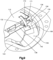
- the gate 110 can include a gate coupler 171 that couples to a traveler coupler 173 on the traveler 116 ( Fig. 8 ).
- One of the gate coupler 171 and the traveler coupler 173 can be a protrusion and the other of the gate coupler 171 and the traveler coupler 173 can be a recess configured to receive the protrusion.
- the traveler coupler 173 can include a lip 175 that engages the gate coupler 171 that mechanically couples the traveler 116 with the gate 110.
- At least one of the gate coupler 171 and the traveler coupler 173 can be a magnet such that the gate coupler 171 and the traveler coupler 173 are magnetically coupled.
- the gate 110 can be fixed relative to the traveler 116 when the gate coupler 171 is coupled with the traveler coupler 173.
- the gate coupler 171 and the traveler coupler 173 can be detachably coupled.
- One of the traveler 116 and the gate 110 can be movable relative to the other of the traveler 116 and the gate 110 when the gate coupler 171 is decoupled from the traveler coupler 173.
- the gate 110 can be configured to stop in the second gate position as the traveler 116 continues to move in the first traveler direction.
- the gate 110 can include a decoupling element 156 configured to at least partially decouple the gate 110 from the traveler 116.
- the decoupling element 156 can interact with the housing 102, 103 to decouple the gate 110 from the traveler 116.
- the decoupling element 156 can be a cantilevered beam that extends from the second end 123 of the body 128.
- the decoupling element 156 can be a protrusion that extends from the second end of the body 128. At least a portion of the decoupling element 156 can be movable relative to the body 128 in the longitudinal direction L.
- the gate coupler 171 can be coupled with the decoupling element 156 such that the gate coupler 171 moves with the decoupling element 156.
- the decoupling element 156 and the gate coupler 171 are a monolithic construct.
- the gate coupler 171 can decouple from the traveler coupler 173 as the decoupling element 156 moves in the longitudinal direction L.
- the second housing member 105 can include an engagement member 158.
- One of the decoupling element 156 and the engagement member 158 can be an inclined surface of the decoupling element 156 and the engagement member 158 can include a contact surface.
- the decoupling element 156 can move in the longitudinal direction L relative to the second housing member 105 in response to engagement of the inclined surface and the contact surface.
- the gate coupler 171 can disengage from the traveler coupler 173 in response to engagement of the inclined surface and the contact surface.
- the friction between the decoupling element 156 and the housing 102 can stop movement of the gate 110 in the first gate direction when the gate coupler 171 disengages from the traveler coupler 173.
- the gate 110 can be in the second gate position when the gate 110 disengages from the traveler 116.
- the gate 110 can be coupled with the housing 102 when the gate is in the third gate position.
- the gate 110 can be decoupled from the traveler 116 when the gate 110 is in the third gate position.
- the gate 110 can engage the housing 102 to prevent movement of the gate 110 in the first gate direction.
- the gate 110 can include a catch 151 that engages a housing catch on the housing 102.
- One of the 151 and the housing catch can be a protrusion and the other of the catch 151 and the housing catch can be a protrusion or recess such that the gate is prevented from moving in the first gate direction when the catch 151 engages the housing catch.
- the decoupling element 156 stops movement of the gate 110 in the first gate direction before the catch 151 engages the housing catch. In other examples, the decoupling element 156 slows movement of the gate 110 and the catch 151 stops movement of the gate 110 when the catch 151 engages the housing catch.
- the second housing member 105 can include a trough 159 and at least a portion of the decoupling element 156 can be within the trough when the gate 110 is in the first gate position such that the gate coupler 171 is engaged with the traveler coupler 173.
- the decoupling element 156 can move out of the trough 159 as the gate 110 moves from the first gate position toward the second gate position.
- the decoupling element 156 can engage the engagement member 158 as the decoupling element 156 moves out of the trough.
- the valve 100 can include features for coupling and decoupling the gate 110 and the traveler 116 other than the gate coupler 171 and the traveler coupler 173.
- a biasing element can decouple the gate 110 from the traveler 116 when the gate 110 is in the second gate position.
- the biasing element can be a spring, torsion spring, piston in cylinder, compressible material such as rubber, or the like.
- the gate 110 and the traveler 116 are coupled to separate shafts and the gate shaft rotation is less than the traveler shaft rotation.
- the gate shaft can be coupled to the traveler shaft or shaft 120 by a sector gear such that the gate shaft rotates less than the traveler shaft.
- one or more spring pins engage the gate 110 to couple or decouple the gate 110 from the traveler 116.
- the spring pin can extend from the traveler 116 and engage the gate 110 such that the gate 110 and traveler 116 rotate in unison.
- the spring pin can retract when the gate 110 is in the second gate position such that the traveler 116 can rotate while the gate 110 remains in the second gate position.
- the spring pin can extend from the housing 102 such that the spring pin stops the gate 110 in the second gate position while allowing the traveler 116 to continue to rotate.
- the traveler 116 can continue to move in the first traveler direction when the decoupling element 156 engages the housing 102.
- the traveler 116 can continue to rotate when the gate coupler 171 decouples from the traveler coupler 173.
- the gate 110 and the traveler 116 can move in unison between the first gate position and the second gate position while the traveler moves from the first traveler position toward the second traveler position.
- the traveler 116 can move relative to each of the housing 102 and the gate 110 as the traveler 116 moves toward the second traveler position when the gate 110 is in the second position.
- the traveler 116 can apply a force to the flap 129 to move the flap 129 when the gate 110 is in the second gate position and the traveler 116 continues to move to the second traveler position.
- One of the flap 129 and the traveler 116 can include an inclined surface that engages the other of the flap 129 and the traveler 116 to move the flap 129 in the longitudinal direction L as the traveler 116 moves relative to the flap 129.
- the flap 129 can move toward the opening 108 in response to movement of the traveler 116 relative to the flap 129.
- the traveler 116 can move the flap 129 from the second gate position ( Fig. 5 ) to the third gate position ( Fig. 6 ).
- the traveler 116 can move the gate 110 in the first gate direction from the first gate position to the second gate position.
- the traveler 116 can move the flap 129 in the second gate direction from the second gate position to the third gate position.
- the flap 129 rotates relative to the body 128 in response to movement of the traveler 116 relative to the flap 129.
- the flap 129 and body 128 move in the longitudinal direction L relative to the housing 102 as the traveler 116 moves relative to the flap 129.
- the gate 110 can include a stopper 132 configured to prevent movement of the gate 110 toward the first gate position.
- the stopper 132 can be a cantilevered beam that extends from the second end of the body 128.
- the stopper 132 can include a first end 131 and a second end 133.
- the first end 131 can be coupled with second end of the body 128.
- the second end 133 of the stopper 132 can be a free end.
- the second end 133 can extend toward the second housing member 105 as the second end 133 extends away from the body 128.
- the stopper 132 can be configured to engage the housing 102.
- the stopper 132 can be configured to engage at least one of the first and second housing members 103, 105. In some examples, the second end 133 engages one of the first and second housing members 103, 105.
- the stopper 132 can be configured to engage an engagement feature 134 on the second housing member 105.
- the second end 133 of the stopper 132 engages the engagement feature 134.
- the stopper 132 can engage the second housing member 105 when the flap 129 is in the third gate position.
- the flap 129 can be engaged with the first housing member 103 when the flap 129 is in the third gate position.
- the gate 110 can simultaneously engage each of the first and second housing members 103, 105 when the flap 129 is in the third gate position.
- At least one of the stopper 132 and the engagement feature 134 can be a protrusion and the other of the stopper 132 and the engagement feature 134 can be a recess configured to receive the protrusion.
- the stopper 132 can be a latch.
- the stopper 132 and the flap 129 can each extend away from the body 128 in the longitudinal direction L.
- the stopper 132 can extend away from the body 128 in the longitudinal direction L by a distance that is greater than the height of the traveler 116.
- the stopper 132 and the flap 129 can each extend away from the body 128 toward the second housing member 105.
- the stopper 132 and the flap 129 can be disposed on opposing sides of the body 128 in the lateral direction A.
- the stopper 132 can be moveable relative to the body 128.
- the stopper 132 can be pivotable relative to the body 128.
- the body 128, the flap 129, and the stopper 132 can be a monolithic construct.
- the stopper 132 and the body 128 can be a monolithic construct.
- the stopper 132 can be coupled with the body 128 by a living hinge.
- the stopper 132 and the body 128 can be separate elements coupled with each other by a hinge.
- the traveler 116 can move in the second traveler direction as the traveler moves from the second traveler position toward the first traveler position.
- the traveler 116 can be configured to engage and move the gate 110 from the third gate position to the first gate position as the traveler 116 moves in the second traveler direction.
- the stopper 132 can prevent movement of the gate 110 toward the first gate position while the stopper 132 is engaged with the engagement feature 134.
- the traveler 116 can include a decoupler 136 configured to disengage the stopper 132 from the engagement feature 134.
- the decoupler 136 can be coupled with the trailing end 119 of the traveler 116.
- One of the decoupler 136 and the stopper 132 can include a tapered edge or ramped surface such that the stopper 132 lifts in response to engagement between the stopper 132 and the decoupler 136.
- the stopper 132 can disengage from the engagement feature 134 as the traveler 116 moves from the second position to the first position.
- the stopper 132 is biased away from the second housing member 105 such that the stopper moves away from the engagement feature 134 once the stopper 132 clears a feature on the first housing member 103.
- the decoupler 136 can move the stopper 132 toward the first housing member 103 as the traveler 116 moves in a second traveler direction opposite the first traveler direction.
- the traveler 116 can include a channel 137 to receive at least a portion of the stopper 132. The stopper 132 can move out of the channel 137 as the traveler 116 moves in the first traveler direction.
- the traveler coupler 173 and gate coupler 171 can be positioned to reengage as the traveler moves from the second traveler position toward the first traveler position.
- the traveler coupler 173 and gate coupler 171 can be positioned to reengage as the traveler moves in the second traveler direction before the stopper 132 disengages from the engagement feature 134.
- the traveler 116 can move the gate 110 from the third gate position to the second gate position.
- the traveler 116 can move the gate 110 from the second gate position to the first gate position.
- the traveler 116 and the gate 110 can each include a trailing engagement feature that engage each other such that the traveler 116 moves the gate 110 in the second traveler direction.
- the traveler 116 can include a traveler trailing engagement feature 138 ( Fig. 8 ) configured to engage a corresponding gate trailing engagement feature 140 ( Fig. 7 ).
- the traveler and gate trailing engagement features 138, 140 maintain engagement of the gate 110 and the traveler 116 to reduce or eliminate friction between the gate 110 and the housing 102.
- the traveler and gate trailing engagement features 138, 140 are abutment surfaces that engage each other as the traveler 116 moves from the second traveler position to the first traveler position.
- one of the traveler trailing engagement feature 138 and the gate trailing engagement feature 140 can be a recess and the other of the traveler trailing engagement feature 138 and the gate trailing engagement feature 140 can be a protrusion configured to be received within the recess.
- the traveler trailing engagement feature 138 can be a protrusion that extends from the trailing end 119 in the second traveler direction.
- the traveler trailing engagement feature 138 and the decoupler 136 can each extend from the trailing end 119 in the second traveler direction.
- the gate trailing engagement feature 140 can be a recess configured to receive the traveler trailing engagement feature 138.
- the recess can be defined by the body 128 and one or more sidewalls 141.
- the sidewalls 141 can extend from the body 128 in the longitudinal direction L.
- the sidewalls 141 can extend from the body 128 toward the second housing member 105.
- a base 142 can be coupled with the sidewalls 141 such that the traveler trailing engagement feature 138 prevents the gate body 128 from moving in the longitudinal direction L as the traveler 116 moves the stopper 132 in the longitudinal direction L.
- the base 142 can be positioned between the traveler trailing engagement feature 138 and the first housing member 103 when the traveler 116 moves in the second traveler direction.
- the traveler trailing engagement feature 138 can be positioned between the gate body 128 and the base 142 in the longitudinal direction L.
- the trailing end 119 can engage the sidewalls 141 so as to apply a force to the gate 110 to move the gate 110 in the second traveler direction.
- the traveler 116 can move the gate 110 from the third gate position to the first gate position as the traveler 116 moves in the second traveler direction.
- the traveler trailing engagement feature 138 can engage with the gate trailing engagement feature 140 as the gate 110 moves from the second gate position to the first gate position.
- the traveler trailing engagement feature 138 can be disengaged from the gate trailing engagement feature 140 as the traveler reaches the second traveler position.
- the traveler trailing engagement feature 138 can reengage the gate trailing engagement feature 140 as the traveler 116 moves from the second traveler position toward the first traveler position.
- the gate trailing engagement feature 140 can be positioned between the gate opening 130 and the stopper 132 in a transverse direction T.
- the transverse direction T can be perpendicular to each of the lateral direction A and the longitudinal direction L.
- the flap 129 is biased toward the first configuration such that the flap 129 moves to the first configuration once the traveler 116 disengages from the flap 129. In other examples, the traveler 116 can move the flap 129 from the second configuration to the first configuration.
- a tab 143 can be coupled with the flap 129 to facilitate movement of the flap 129 from the third gate position to the second gate position.
- the tab 143 can be generally parallel to the body 128 when the flap 129 is in the second gate position.
- the tab 143 can be disposed at an angle relative to the flap 129. An angle between a surface of the flap 129 and a surface of the tab 143 can be equal to the first angle.
- the tab 143 can move toward the first housing member 103 as the flap 129 rotates about the second axis A 2 as the traveler 116 moves in the first traveler direction.
- the tab 143 can move into a tab channel 145 ( Fig. 8 ) in the traveler 116 as the traveler 116 moves in the second traveler direction.
- the tab channel 145 can be positioned between the hub 126 and the decoupler 136 in the transverse direction T.
- the tab 143 can engage a surface of the tab channel 145 as the traveler 116 moves in the second traveler direction.
- the inclined surface can cause the tab 143, and therefore the flap 129, to move in a fourth gate direction opposite the third gate direction.
- the fourth gate direction can be rotational about the second axis A 2 .
- the flap 129 can move in the fourth gate direction as the flap 129 moves from the third gate position to the second gate position.
- the valve 100 can include an actuator 144 configured to move the shaft 120.
- the actuator 144 can rotate the shaft 120 about the first axis A 1 .
- the actuator 144 can be manually engageable.
- the actuator 144 can be a handle.
- a user can engage the actuator 144 and apply a force thereto to rotate the actuator 144 about the first axis A 1 .
- the actuator 144 can be a push button or lever.
- the actuator 144 can be a motor that rotates the shaft 120.
- the actuator 144 can be rotationally fixed relative to the shaft 120.
- the actuator 144 can rotate the shaft 120, thereby rotating the traveler 116.
- contact between the tool 162 and the housing 102 and/or cover 107 can engage actuator 144.
- the housing 102 and/or cover 107 can include a switch (e.g., a pressure plate or electric contact) that engages the tool 162 and causes the actuator 144 to reversibly open the valve 100 or shut the valve 100.
- the actuator can include locking and/or retaining features to hold the tool 162 against a surface of the valve (e.g., an o-ring or other compliant surface) to reduce or eliminate the quantity of material that enters the valve 100 and/or the opening 108 while the actuator 144 is active. In this way, at least a portion of the operations of the valve 100 can be automated (e.g., undertaken without human intervention) or pseudo-automated (e.g., initiated with human intervention), as well as a manual process.
- the valve 100 can be detachably coupled with a tool 162 configured to introduce material into, or receive material from, the valve 100.
- the tool 162 can be at least temporarily locked to the valve 100.
- the tool 162 can be locked to the valve 100 as the valve transitions from the closed configuration to the open configuration and back to the closed configuration.
- One of the tool 162 and the valve 100 can include a lock that locks the tool 162 with the valve 100.
- a cover 107 can be coupled with the housing 102.
- the cover 107 can include an opening that receives the tool 162.
- the cover 107 can include the lock.
- the lock can be a bayonet fitting.
- One of the cover 107 and the tool 162 can include a protrusion and the other of the cover 107 and the tool 162 can include a recess that receives the protrusion.
- the protrusion can be positioned in the recess in response to movement of the tool 162 relative to the cover 107.
- the protrusion within the recess can lock the tool 162 to the valve 100.
- the actuator 144 can lock the apparatus to the housing, activate the secondary outlet 160, and transition the gate 110 from the first gate position to the third gate position in a single actuation step. In other examples, locking the tool 162 to the housing 102 and transitioning the gate 110 can be separate steps. In other examples, multiple actuators can be used.
- Fig. 10 is a schematic illustration of relative movement between the gate 110, the traveler 116, and the housing 102.
- the valve 100 can be open when the actuator 144 is in a first actuator position.
- the traveler 116 can begin to move from the first traveler position toward the second traveler position as the actuator 144 moves from a first actuator position to a second actuator position.
- the traveler 116 can engage the gate 110 and move the gate 110 from the first gate position to the second gate position as the traveler 116 moves from the first traveler position toward the second traveler position.
- the gate 110 can engage the housing 102 as the gate moves toward the second gate position. At least a portion of the gate 110 can be positioned over the seal adjacent the opening 108 when the gate is in the second position.
- the gate 110 can be in the second position when the actuator 144 is in a second actuator position.
- the gate 110 can decouple from the traveler 116 when the gate 110 is in the second gate position such that the gate 110 stops and the traveler 116 continues to move toward the second traveler position.
- the traveler 116 can engage the flap 129 after decoupling from the gate 110.
- the flap 129 can begin to move as the traveler 116 engages the flap 129.
- the gate 110 can engage the seal as the gate 110 moves toward the third gate position.
- the gate 110 can seal the opening 108 when the gate 110 is in the third gate position.
- the housing 102 can be engaged with the gate 110 when the gate is in the third gate position.
- the valve 100 can be closed when the gate 110 is in the third gate position.
- the actuator 144 can be in a third actuator position when the gate is in the third gate position.
- the tool 162 can be locked to the housing 102 as the actuator moves from the first actuator position to the third actuator position.
- the tool 162 can be unlocked as the actuator moves from the third actuator position to a fourth actuator position.
- the tool 162 can be disengageable from the housing 102 when the actuator 144 is in the fourth actuator position.
- Moving the actuator 144 from the fourth actuator position to the third actuator position while the tool 162 is engaged with the housing 102 can begin an opening sequence for the valve 100.
- tool 162 must be engaged with the housing to allow the actuator 144 to move from the fourth actuator position to the third actuator position.
- the tool 162 can be locked to the housing 102 as the actuator moves from the fourth actuator position to the third actuator position.
- the traveler 116 can move from the second traveler position toward the first traveler position as the actuator 144 moves from the fourth actuator position toward the third actuator position.
- the gate 110 can be in the third gate position as the actuator 144 moves from the fourth actuator position toward the third actuator position.
- the traveler 116 can decrease pressure on the gate 110 as the actuator 144 moves from the third actuator position toward the second actuator position.
- the flap 129 can move away from the housing 102 as the actuator moves from the third actuator position toward the second actuator position.
- the opening can be unsealed as the flap 129 moves away from the housing 102.
- the traveler 116 can couple to the gate 110 as the traveler 116 moves toward the first traveler position.
- the gate 110 can disengage from the housing 102 as the gate 110 moves from the third gate position toward the second gate position.
- the gate 110 can be in the second gate position when the actuator 144 is in the second actuator position.
- the gate 110 and the traveler 116 can move toward their first positions as the actor moves to the first actuator position such that the valve 100 is open.
- the housing 102 can define a cavity between the first housing member 103 and the second housing member 105.
- the valve 100 can be configured to purge material out of the cavity. In some examples, the valve 100 purges material from the cavity after the valve is closed. In other examples, the valve 100 purges material from the cavity prior to opening the valve 100.
- the valve 100 can be configured to reduce pressure within the cavity prior to opening the valve 100 so as to minimize or eliminate a surge of material from the cavity into a component with which the valve 100 is coupled.
- the valve 100 can include a secondary outlet 160 ( Fig. 1 ) configured to purge the cavity of any material.
- the secondary outlet 160 can be a vacuum that removes any gas or fluid from the cavity.
- the secondary outlet 160 can introduce an inert gas into the cavity and then remove the inert gas from the cavity.
- the secondary outlet 160 can also reduce any pressure differential between the inlet and outlets of the valve 100.
- the secondary outlet 160 can be activated in response to movement of the actuator 144.
- the inlet of the valve 100 can be sealed prior to purging the cavity.
- the inlet can be sealed by a plug, apparatus, or by a second gate.
- the second gate can be the same as the gate 110.
- the traveler 116 can move the second gate into a sealed position as the traveler 116 moves the gate 110 from the first gate position to the third gate position.
- Opposing sides of the traveler 116 in the longitudinal direction L can be mirror images of each other to facilitate interaction of the traveler 116 with the second gate.
- the traveler 116 can simultaneously move the gate 110 and the second gate into sealed configurations.
Landscapes
- Engineering & Computer Science (AREA)
- General Engineering & Computer Science (AREA)
- Mechanical Engineering (AREA)
- Sliding Valves (AREA)
Abstract
A valve can include a housing, a gate (110), and a traveler (116). The housing can include an opening such that material can flow through the opening from the first side to the second side. The gate can be moveable relative to the housing in a first direction between a first gate position and a second gate position. The gate can be moveable relative to the housing in a second direction between the second gate position and a third gate position. The gate can allow material flow through the opening in the first gate position and preventing material flow through the opening in the third gate position. The traveler can be moveable from a first traveler position to a second traveler position. The traveler can be configured to move the gate in the first and second directions as the traveler moves from the first traveler position to the second traveler position.
Description
- This disclosure relates generally to a valve and, more particularly, to a pendulum valve.
- Many analytical instruments require controlled and accurate liquid or gas flow through the instrument during analytical processing. Some of the types of analytical instruments in which precise liquid or gas flow is desired are mass spectrometers, gas-chromatography-mass-spectrometry systems (GCMS), liquid-chromatography-mass-spectrometry systems (LCMS), or other instruments that are configured to receive solid, powder, liquid and/or gas samples and to generate a characteristic signal describing one or more chemical, physical, and/or structural properties of the sample.
- Analytical instruments may include a valve to temporarily isolate, or allow passage of material to, one volume from another. The material can flow through an opening in the valve. The valves can include a seal surrounding the opening and a surface that engages and disengages the seal as the valve opens and closes. Contaminants can enter the analytical instrument if the valve seal breaks down.
- Some valves, such as ball valves with polytetrafluoroethylene (PTFE) seats, can apply a shear force to the seal as the valve opens and closes due to the continuous pressure applied to maintain sufficient seal engagement with the ball. Such valves can use harder seal materials, such as plastics, to withstand these shear forces. However, harder seal materials can be subject to wear over time which can lead to bits of the seal material breaking off and entering the analytical instrument through the valve. These valves are also not well suited for compact applications due to the relationship between the size of the ball component and the size of the valve passage needed for an application.
- Other valve types, such as gate or pendulum valves, can have a shorter passage for a given valve opening size, and can use softer seal materials. However, softer seal materials are not ideally suited for shear forces. The gate or pendulum valves are therefore designed to avoid shear forces on the seal. These valves can first move the seal over the opening before moving the seal closed. Some gate or pendulum valves incorporate a cam, a second motor, mechanical linkage, or pneumatic action to press the seal closed after it has been moved into place. However, these designs can require multiple actuation motions or may require parts that can be more costly or complicated to manufacture. Therefore, an improved valve that is durable with compact form, reduced complexity and part count, and reduced entrainment of particulates is desired.
- The foregoing background discussion is intended solely to aid the reader. It is not intended to limit the innovations described herein. Thus, the foregoing discussion should not be taken to indicate that any particular element of a prior system is unsuitable for use with the innovations described herein, nor is it intended to indicate that any element is essential in implementing the innovations described herein.
- A valve can include a housing, a gate, and a traveler. The housing can include a first side and a second side opposite the first side. The housing can include an opening such that material can pass through the opening from the first side to the second side. The gate can be disposed within a cavity defined by the housing. The gate can be moveable relative to the housing in a first direction between a first gate position and a second gate position. At least a portion of the gate can be moveable relative to the housing in a second direction between the second gate position and a third gate position. The second direction can be different from the first direction. The gate can allow material flow through the opening in the first gate position and preventing material flow through the opening in the third gate position. The traveler can be disposed within the cavity. The traveler can be moveable from a first traveler position to a second traveler position. The traveler can be configured to move the gate in the first and second directions as the traveler moves from the first traveler position to the second traveler position. The traveler can include an abutment surface to apply a force to an inclined surface of the gate to move the portion of the gate between the second gate position and the third gate position.
- The gate can rotate about a gate axis as the gate moves in the first direction. The portion of the gate can be a gate flap coupled with a gate body and angularly displaceable relative to the gate body from a first gate flap position to a second gate flap position as the gate flap moves in the second direction. At least one of the housing and the gate can include a seal cavity and the valve can include a seal disposed at least partially within the seal cavity, the seal engaged with the housing and the gate when the gate is in the third gate position such that the seal is disposed around at least a portion of the opening. The seal can be disengaged from at least one of the gate and the housing as the gate moves from the first gate position to the second gate position. The traveler can rotate about a traveler axis as the traveler moves from the first traveler position to the second traveler position. The gate body can include a first end and a second end spaced from the first end in a lateral direction. The gate flap can extend from the gate body toward the traveler in a longitudinal direction different from the lateral direction so as to define a first angle between the gate body and the gate flap. The abutment surface of the traveler can engage the gate flap such that the gate is fixed relative to the traveler as the gate moves from the first gate position to the second gate position.
- In a further embodiment, the valve includes a shaft and a seal disposed about the shaft, the seal configured to permit purging the cavity. The gate can move linearly as the gate moves from the second gate position to the third gate position. The abutment surface can apply a force to the gate flap in a force direction different from the first direction such that the gate flap moves between the second gate position and the third gate position so as to define a second angle between the gate flap and the gate body, the second angle different from the first angle.
- In a further embodiment, the valve includes a shaft and an actuator rotationally fixed to the shaft. The gate can include a gate shaft opening and the shaft is disposed in the gate shaft opening such that the gate is rotatable relative to the shaft. The traveler can include a traveler shaft opening defined by a sidewall with the shaft disposed in the traveler shaft opening, at least one of the shaft and the sidewall including a protrusion and the other of the shaft and the sidewall including a recess to receive the protrusion such that the traveler is rotationally fixed to the shaft. Rotation of the actuator can rotate the traveler. The valve can include a secondary outlet configured to facilitate material movement into or from the cavity when the gate is in the third gate position. One of the gate and the housing can include an inclined surface and the other of the gate and the housing can include a contact surface such that the gate moves relative to the housing in a third direction different from the first direction in response to engagement of the contact surface and the inclined surface.
- An analytical instrument can include a housing, a shaft, a gate, a traveler, an apparatus, and an actuator. The housing can define a cavity and an opening in communication with the cavity such that material can pass through the opening into or out of the cavity. The shaft can be rotatable relative to the housing. The gate can be disposed within the cavity, the gate moveable relative to the housing between a sealed position and an unsealed position, the gate allowing material passage through the opening in the unsealed position and preventing material passage through the opening in the sealed position. The traveler can be rotationally fixed to the shaft and disposed within the cavity, the traveler including a trailing end and a leading end spaced from the trailing end in a first direction, wherein the leading end engages an inclined surface of the gate as the traveler moves in the first direction from a first traveler position to a second traveler position so as to move the gate from the unsealed position to the sealed position. The apparatus can be configured to couple with the housing, the apparatus containing material such that material moves from the apparatus through the opening. The actuator can be rotationally fixed to the shaft such that the traveler moves from the first traveler position to the second traveler position in response to rotation of the actuator.
- The gate can be fixed relative to the traveler in the in the first direction as the gate moves from the unsealed position toward the sealed position. One of the gate and the housing can include a protrusion and the other of the gate and the housing can include a recess such that the position of the gate is fixed relative to the housing when the protrusion is within the recess. The traveler can move relative to each of the gate and the housing when the protrusion is within the recess. The gate can include a gate body and a gate flap rotatably coupled with the gate body such that the gate flap rotates relative to the gate body from a first gate flap position to a second gate flap position as the gate moves from the unsealed position to the sealed position. The gate can include an end wall transverse to the gate body and the trailing end of the traveler includes a trailing end abutment surface that engages the end wall so as to move the gate from the sealed position to the unsealed position as the traveler moves in a second direction opposite the first direction. The analytical instrument can include a secondary outlet in fluid communication with the cavity, the secondary outlet configured to purge the cavity when the gate is in the sealed position. Rotation of the actuator can couple the apparatus to the housing and moves the gate to the unsealed position. The gate can move in a first gate direction from the unsealed position to the sealed position. One of the housing and the gate include an inclined surface and the other of the housing and the gate include an engagement surface such that the gate moves relative to the housing in a longitudinal direction different from the first gate direction as the gate moves from the unsealed position to the sealed position.
- Specifically, an aspect of the invention is defined by an analytical instrument comprising a housing defining a cavity and an opening in communication with the cavity such that material can pass through the opening into or out of the cavity; a shaft rotatable relative to the housing; a gate disposed within the cavity, the gate moveable relative to the housing between a sealed position and an unsealed position, the gate allowing material passage through the opening in the unsealed position and preventing material passage through the opening in the sealed position; a traveler rotationally fixed to the shaft and disposed within the cavity, the traveler including a trailing end and a leading end spaced from the trailing end in a first direction, wherein the leading end engages an inclined surface of the gate as the traveler moves in the first direction from a first traveler position to a second traveler position so as to move the gate from the unsealed position to the sealed position; an apparatus configured to couple with the housing, the apparatus containing material such that material moves from the apparatus through the opening; and an actuator rotationally fixed to the shaft such that the traveler moves from the first traveler position to the second traveler position in response to rotation of the actuator.
- In the analytical instrument of the invention, the gate may be fixed relative to the traveler in the first direction as the gate moves from the unsealed position toward the sealed position. In that case, preferably, one of the gate and the housing may include a protrusion and the other of the gate and the housing may include a recess such that the position of the gate is fixed relative to the housing when the protrusion is within the recess.
- Still more preferably in that case, the traveler may move relative to each of the gate and the housing when the protrusion is within the recess.
- In the analytical instrument of the invention, the gate may include a gate body and a gate flap rotatably coupled with the gate body such that the gate flap rotates relative to the gate body from a first gate flap position to a second gate flap position as the gate moves from the unsealed position to the sealed position.
- In that case, preferably, the gate includes an end wall transverse to the gate body and the trailing end of the traveler includes a trailing end abutment surface that engages the end wall so as to move the gate from the sealed position to the unsealed position as the traveler moves in a second direction opposite the first direction.
- The analytical instrument of the present invention may further comprise a secondary outlet in fluid communication with the cavity, the secondary outlet being configured to purge the cavity when the gate is in the sealed position.
- Preferably, rotation of the actuator couples the apparatus to the housing and moves the gate to the unsealed position.
- Preferably, the gate moves in a first gate direction from the unsealed position to the sealed position, and wherein one of the housing and the gate include an inclined surface and the other of the housing and the gate include an engagement surface such that the gate moves relative to the housing in a longitudinal direction different from the first gate direction as the gate moves from the unsealed position to the sealed position.
- This summary is provided to introduce a selection of concepts in a simplified form that are further described below in the Detailed Description section. This Summary is not intended to identify key features or essential features of the claimed subject matter, nor is it intended to be used to limit the scope of the claimed subject matter. Furthermore, the claimed subject matter is not constrained to limitations that solve any or all disadvantages noted in any part of this disclosure.
- The foregoing summary, as well as the following detailed description of illustrative embodiments of the present application, will be better understood when read in conjunction with the appended drawings. For the purposes of illustrating the present application, there are shown in the drawings illustrative embodiments of the disclosure. It should be understood, however, that the application is not limited to the precise arrangements and instrumentalities shown. In the drawings:
-
Fig. 1 is a top perspective view of an analytical instrument including a valve and an apparatus in according to an aspect of this disclosure; -
Fig. 2 is a top plan view of a portion of a first housing member, a traveler, and a gate ofFig. 1 with the traveler and the gate in their respective first positions; -
Fig. 3 is a top plan view of the first housing member, the traveler, and the gate ofFig. 1 with the gate in a second gate position; -
Fig. 4 is a top perspective view of the first housing member, the traveler, and the gate ofFig. 1 with the gate in a third gate position and the traveler in a second traveler position; -
Fig. 5 is a top perspective view of an actuator, first housing member, the traveler, and the gate ofFig. 1 with the gate in the second gate position and the traveler between the first traveler position and the second traveler position; -
Fig. 6 is a top perspective view of the actuator, first housing member, the traveler, and the gate ofFig. 1 with the gate in the third gate position and the traveler in the second traveler position; -
Fig. 7 is a bottom perspective view of the gate ofFig. 1 ; -
Fig. 8 is a bottom perspective view of the traveler ofFig. 1 ; -
Fig. 9 is a bottom perspective view of the second housing member, the traveler, and the gate ofFig. 1 with the gate coupled with the housing just prior to engagement between the traveler and the gate; and -
Fig. 10 is a schematic diagram illustrating movement of the components of the valve ofFig. 1 . - Certain terminology used in this description is for convenience only and is not limiting. The words "axial", "radial", "circumferential", "outward", "inward", "upper," and "lower" designate directions in the drawings to which reference is made. As used herein, the terms "substantially" or "about" and derivatives thereof, and words of similar import, when used to describe a size, shape, orientation, distance, spatial relationship, or other parameter includes the stated size, shape, orientation, distance, spatial relationship, or other parameter, and can also include a range up to 10% more and up to 10% less than the stated parameter, including 5% more and 5% less, including 3% more and 3% less, including 1% more and 1% less. All ranges disclosed herein are inclusive of the recited endpoint and independently combinable. The terminology includes the above-listed words, derivatives thereof and words of similar import.
- An analytical instrument can include a valve that prevents material passage between internal and or external regions. The analytical instrument can be a mass spectrometer, gas-chromatography-mass-spectrometry system (GCMS), liquid- chromatography-mass-spectrometry system (LCMS), or other instrument that is configured to receive solid, powder, liquid and/or gas samples and to generate a characteristic signal describing one or more chemical, physical, and/or structural properties of the sample. The valve can isolate a first side from a second side when the valve is closed. The valve can be opened to allow material to transfer through an opening in a housing between the input and the output. The valve can include a gate that seals an opening in a sealed position and allows material passage in an unsealed position. A seal can be positioned about the opening such that the seal is sealingly engaged with the gate and the housing when the valve gate is in the sealed position. At least one of the gate and the housing disengage from the seal as the gate moves from the sealed position to the unsealed position. A valve that applies a shear force to the seal can result in excessive wear to the seal. The valve described herein can minimize or avoid any shear forces applied to the seal to prolong the useful life of the seal and reduce or eliminate entrainment of seal material through the cavity into the analytical instrument. The gate can be sequentially moveable in a first direction and a second direction different from the first direction so as to avoid excess wear on a seal when moving between the unsealed and sealed positions. The valve described herein can minimize or avoid any shear forces applied to the seal while having a compact form perpendicular to the valve opening and a low part count for economic construction. The valve described herein can employ a single actuation motion to move a gate over an opening and moving the gate into sealing engagement to close the valve. The valve described herein ensures correct placement and compression of the gate and a seal without requiring secondary actuators.
- Existing valves can allow material to remain within the cavity after the valve is closed. That remaining material can pass through the opening when the valve is reopened. This can be undesirable when different materials are being introduced into the cavity during a subsequent use of the valve. The
valve 100 described herein can be configured to purge material out of the cavity before use. Thevalve 100 can be purged to reduce pressure within the cavity. The pressure within the cavity can be equalized with the pressure within a component with which thevalve 100 is coupled. - The valve can include an actuator that moves the gate between the sealed and unsealed positions. In some examples, the actuator also locks an apparatus or tool to a housing. The actuator can lock the apparatus to the housing and move the gate in a single motion. The actuator can lock the apparatus to the housing, activate the secondary outlet, and move the gate in a single motion. Existing valves can require a user to secure a sample container thereto and then open the valve after the securing step. The valve described herein can lock the apparatus to the housing and open the valve in a single step.
- Referring to
Fig. 1 , avalve 100 is shown. Thevalve 100 can include ahousing 102 having afirst side 104 and asecond side 106. Thefirst side 104 can be opposite thesecond side 106 in a longitudinal direction L. Thehousing 102 can include first and second edges opposite each other in a lateral direction A. The lateral direction A can be perpendicular to the longitudinal direction L. Thehousing 102 can include first and second ends opposite each other in a transverse direction T. The transverse direction T can be perpendicular to each of the lateral and longitudinal directions A, L. Thehousing 102 can have a generally rectangular shape as shown inFig. 1 . In other examples, thehousing 102 can be circular, semi-circular, triangular, oval, or pentagonal. In some examples, thehousing 102 includes afirst housing member 103 and asecond housing member 105. In other examples, thehousing 102 is a monolithic construct. Thefirst housing member 103 can be disposed on thefirst side 104 of thehousing 102. Thesecond housing member 105 can be disposed on thesecond side 106 of thehousing 102. The first andsecond members valve 100. - The
valve 100 can include a sealing element to form a fluid tight seal between the first andsecond housing members Fig. 2 , thefirst housing member 103 can include arecess 113 configured to receive the sealing element. In other examples, thesecond housing member 105 can include therecess 113. In still other examples, each of the first andsecond housing members recess 113. The sealing element can be an o-ring, a gasket, a foam, a hardening (for example, epoxy) or non-hardening (for example, silicone) joining or sealing material, a compressed metal-to-metal interface, a weld, a braze, and or other common joining and sealing methods. - Referring to
Fig. 2 , anopening 108 can extend through thehousing 102. Theopening 108 can extend through thefirst housing member 103. Theopening 108 can extend through thesecond housing member 105. Theopening 108 has a circular shape inFig. 2 . In other examples, theopening 108 can have a triangular, rectangular, pentagonal, or other polygonal shape. Theopening 108 can have an irregular shape. Material can pass through theopening 108 when thevalve 100 is in an unsealed configuration. The material can be gas, liquid, or solid (e.g., pure gas, gas mixture, liquid, powder, etc.). The material can be a combination of two or more of a gas, liquid, and solid (e.g., a suspension, colloid, etc.). Theopening 108 can allow material to pass through thevalve 100 from a high pressure receptacle to a low pressure receptacle. In an illustrative example, an analytical instrument can include a relative negative pressure region that is reversibly sealed from an ambient environment by thevalve 100. In this way, the material can be contained within a vessel or tool at about ambient pressure (e.g., a higher pressure region), and can be introduced into the analytical instrument by pressure-driven flow. - The
valve 100 can include agate 110 that can prevent material passage through theopening 108. Thegate 110 can allow material flow through theopening 108 in a first gate position (Fig. 2 ). Thegate 110 can move from the first gate position (Fig. 3 ) to a second gate position (Fig. 3 ) to a third gate position (Fig. 4 ). The gate can prevent material flow through theopening 108 in the third gate position. Thevalve 100 can be in the unsealed configuration when thegate 110 is in the first gate position. Thevalve 100 can be in the sealed configuration when the gate is in the third gate position. - The
gate 110 can move in a first gate direction as thegate 110 moves from the first gate position to the second gate position. Thegate 110 can pivot about a gate axis as thegate 110 moves from the first gate position to the second position. In some examples, thegate 110 rotates about a first axis A1 (Fig. 2 ) as thegate 110 moves from the first gate position to the second gate position. The first axis A1 can be a gate pivot axis. The first axis A1 can be elongate in the longitudinal direction L. In other examples, thegate 110 can move linearly between the first and second gate positions. The first gate direction can be along direction D1 inFig. 2 . In other examples, thegate 110 can move linearly between the first and second gate positions. At least a portion of thegate 110 can move in a second gate direction between the second gate position (Fig. 5 ) and a third gate position (Fig. 6 ). The second gate direction can include movement in the longitudinal direction L. The second gate direction can be parallel to the longitudinal direction L. The first gate direction can be different from the second gate direction. The second gate direction can be transverse to the first gate direction. Thevalve 100 can transition from the unsealed configuration to the sealed configuration as the gate moves from the first gate position to the third gate position. - The
gate 110 can interact with thehousing 102 to disengage thegate 110 from thetraveler 116. Thegate 110 can interact with thehousing 102 as thegate 110 moves to the second gate position. For example, one of thegate 110 and thehousing 102 can include a ramped surface and the other of thegate 110 and the housing can include an engagement surface such that thegate 110 moves in the second gate direction as at least one of the ramped surface and engagement surface moves relative to the other of the ramped surface and the engagement surface. - Referring to
Fig. 7 , thegate 110 can include abody 128 and aflap 129. Theflap 129 can be configured to seal theopening 108. In some examples, theflap 129 has a semi-circular shape. In other examples, theflap 129 can have a rectangular, triangular, trapezoidal, or other polygonal shape. Theflap 129 can have a surface area larger than a surface area of theopening 108. - The
flap 129 can include afirst end 121 and asecond end 123 spaced from the first end. Thefirst end 121 can be coupled with thebody 128. Thesecond end 123 can be a free end. Theflap 129 can be movable relative to thebody 128. Theflap 129 can be angularly displaceable relative to thebody 128. Theflap 129 be pivotable relative to thebody 128 about a second gate axis A2. In some examples, theflap 129 pivots relative to thebody 128 about the second gate axis A2 as thegate 110 moves between the second and third gate positions. In other examples, theflap 129 moves approximately linearly between the second and third gate positions. In other examples, theflap 129 and thebody 128 are fixed relative to each other and both theflap 129 and thebody 128 move as thegate 110 moves from between the second and third gate positions. For example, theflap 129 and thebody 128 could both move in the longitudinal direction L as thegate 110 moves between the second and third gate positions. - The
body 128 can include a first end and a second end spaced from the first end in the first gate direction. Theflap 129 can be coupled with thebody 128. Theflap 129 can be coupled with the first end of thebody 128. Theflap 129 and thebody 128 can be a monolithic construct. In some examples, theflap 129 andbody 128 are manufactured from a flexible material such that theflap 129 is pivotable relative to thebody 128 without plastically deforming theflap 129 orbody 128. In other examples, theflap 129 and thebody 128 are separate elements coupled by a hinge. - The
flap 129 can include one or morefirst portions 125 coupled with thebody 128. Thefirst portion 125 can be a connecting element. Thefirst portion 125 can be a bridging structure. Thefirst portion 125 can be connected to thebody 128. Thefirst portion 125 can be connected to an intermediate portion between theflap 129 and thebody 128. Thefirst portion 125 can be coupled with a hinge that is coupled with thebody 128. Theflap 129 can be coupled with thebody 128 by the one or morefirst portions 125. - The
flap 129 can include asecond portion 127. Thesecond portion 127 can be spaced from thebody 128. Thesecond portion 127 can be spaced from thebody 128 by a relief. The relief can extend along a portion of thefirst end 121 of theflap 129. In some examples, the relief is a portion that has a reduced thickness compared to theflap 129 and thebody 128. In other examples, the relief is a space such that thesecond portion 127 is not connected to thebody 128. In other examples, thesecond portion 127 is connected to thebody 128 along the length of the intersection of thesecond portion 127 and thebody 128. - In some examples, one of the first and
second portions second portion intermediate portion 154 can be positioned between thefirst portion 125 and thesecond portion 127. Theintermediate portion 154 can be a relief cut that extends through theflap 129. In other examples, theintermediate portion 154 is configured to expand and contract such that one of the first andsecond portions second portion intermediate portion 154 has a smaller thickness than the first andsecond portions second portions body 128. - The
flap 129 can be movable from a first configuration (Fig. 5 ) to a second configuration (Fig. 6 ). Theflap 129 can be biased toward the first configuration. Theflap 129 can pivot from the first configuration to the second configuration. Movement of theflap 129 from the first configuration to the second configuration can transition thegate 110 from the second gate position to the third gate position. Theflap 129 can extend from the first end of thebody 128 away from thefirst housing member 103 in the first configuration. Theflap 129 can be disposed at a first angle relative to thebody 128 in the first configuration. Theflap 129 can be disposed at a second angle relative to thebody 128 in the second configuration. The first angle can be less than the second angle. For example, the second angle can be closer to 180 degrees than the first angle. In other examples, theflap 129 is disposed at a fixed angle relative to thebody 128 and thegate 110 moves in the second gate direction as thegate 110 moves between the second and third gate positions. - In some examples, the
gate 110 moves sequentially in the first and second gate directions as thegate 110 moves between the first and third gate positions. Theflap 129 can be fixed in the second gate direction as thegate 110 moves in the first gate direction. Thebody 128 of thegate 110 can be fixed in the first gate direction as theflap 129 moves in the second gate direction. In some examples, theflap 129 is fixed in the second gate direction during an initial movement of thegate 110 in the first gate direction, then theflap 129 moves in the second gate direction. In other examples, theflap 129 moves in the first and second gate directions simultaneously. - The
gate 110 can pivot about the first axis A1 as thegate 110 moves from the first gate position to the second gate position and theflap 129 pivots about the second axis A2 from the second gate position to the third gate position. In other examples, thegate 110 can pivot about the first axis A1 as the gate moves from the first gate position to the second gate position and theflap 129 moves linearly from the second gate position to the third gate position. In still other examples, thegate 110 can move linearly as the gate moves from the first gate position to the second gate position and theflap 129 rotates about the second axis A2 from the second gate position to the third gate position. - A fluid tight seal can be established between the
gate 110 and thehousing 102 as theflap 129 moves from the second gate position to the third gate position. Aseal 112 can be coupled with thehousing 102 and thegate 110 when theflap 129 is in the third gate position to establish a vacuum or fluid tight seal. One example of aseal 112 is shown inFig. 2 . Theseal 112 can be an O-ring. Theseal 112 can be made from a flexible material. Theseal 112 can be a solid or foam, synthetic or natural rubber, or plastic, or a combination thereof (for example, Buna-N, EPDM, FEPM, FKM, FFKM, fluroelastomer, fluoropolymer, fluorosilicone, neoprene, polypropylene, polyurethane, PTFE, silicone, TFE/P). Theseal 112 can be an independent part from, bonded to, held mechanically to, and or a coating on, thehousing 102 orflap 129. The sealing surfaces on thehousing 102 andflap 129 can have specific surface preparations (for example, grinding, mechanical polishing, plating, electro-polishing) to obtain sufficient surface flatness and minimal surface roughness needed to effectively seal. Theseal 112 can be configured to flex into sealing engagement with each of thehousing 102 and thegate 110 as thegate 110 moves from the second gate position to the third gate position. In some examples, theseal 112 is fixed to thehousing 102. In other examples, theseal 112 is fixed to theflap 129. In other examples, aseal 112 is fixed to thehousing 102 and aseal 112 is fixed to theflap 129. Thehousing 102 can include a seal cavity configured to receive at least a portion of theseal 112. The seal cavity can extend from an interior surface toward an exterior surface of thefirst housing member 103. - The
flap 129 can move into engagement with theseal 112 as theflap 129 moves in the second gate direction. The second gate direction can be substantially perpendicular to an upper surface of thefirst housing member 103. The upper surface can be the surface that confronts thesecond housing member 105. Theflap 129 can apply a substantially compressive force to theseal 112 when the second gate direction is substantially perpendicular to the upper surface. The second direction being substantially perpendicular to the upper surface can avoid shearing forces being applied to theseal 112 by thegate 110 and thehousing 102. The useful life of theseal 112 can be prolonged by minimizing or avoiding shear forces on theseal 112. The second direction being substantially perpendicular to thefirst side 104 can reduce friction on theseal 112 from theflap 129. - Referring to
Fig. 2 , thevalve 100 can include atraveler 116 configured to move thegate 110 between the first and second gate positions. Theflap 129 can interact with thetraveler 116 to move theflap 129 between the first and second configurations. Thetraveler 116 can interact with theflap 129 to move thegate 110 from the second gate position to the third gate position. One of theflap 129 and thetraveler 116 can define an inclined surface engageable by the other of theflap 129 and thetraveler 116. In some examples, thetraveler 116 can apply a force to the inclined surface of theflap 129 to move theflap 129 in the second gate direction. In other examples, thetraveler 116 expands to move theflap 129 in the second gate direction. - The
traveler 116 can be configured to move from a first traveler position (Fig. 2 ) to a second traveler position (Fig. 4 ). Thetraveler 116 can move in a first traveler direction as thetraveler 116 moves from the first traveler position to the second traveler position. The first traveler direction can be along the direction D1 (Fig. 2 ). Thetraveler 116 can pivot about a traveler axis as thetraveler 116 moves from the first traveler position to the second traveler position. In other examples, thetraveler 116 can move along a linear axis. The traveler axis can be parallel to the gate axis. The traveler axis and the gate axis can be colinear. The traveler axis and the gate axis can be the same axis. Thetraveler 116 can pivot about the first axis A1 as thetraveler 116 moves between the first and second traveler positions. - The
traveler 116 and thegate 110 can simultaneously move in the first traveler direction and the first gate direction, respectively. The first gate direction and the first traveler direction can be the same direction. The position of thegate 110 can be fixed relative to thetraveler 116 as thegate 110 moves between the first and second gate positions. - The
gate 110 can be positioned between thetraveler 116 and thefirst housing member 103. Thegate 110 can be positioned between thetraveler 116 and thefirst housing member 103 in the longitudinal direction L. Thetraveler 116 can be positioned between thesecond housing member 105 and thegate 110. At least a portion of thegate 110 can be disposed in the path of thetraveler 116 such that thetraveler 116 contacts thegate 110 as thetraveler 116 moves from the first traveler position to the second traveler position. For example, a distance between thesecond end 123 of theflap 129 and thesecond housing member 105 can be less than a height of thetraveler 116 such that at least a portion of theflap 129 is disposed in the path of thetraveler 116. - The
traveler 116 can be configured to couple with ashaft 120. Theshaft 120 can extend through a portion of thehousing 102. A seal can be disposed about theshaft 120. The seal can sealingly engage theshaft 120 and thehousing 102. - Referring to
Fig. 8 , thetraveler 116 can include anopening 118 configured to receive theshaft 120. Thetraveler 116 can be rotationally fixed to theshaft 120 when theshaft 120 is in theopening 118. Theopening 118 can be defined by asidewall 122. Thesidewall 122 can include akeyway 124 to receive a key to rotationally fix thetraveler 116 to theshaft 120. In other examples, theshaft 120 can be rotationally fixed to thetraveler 116 by the shape of theopening 118 andshaft 120, a fastener, adhesive, weld, or other common joining methods. In other examples theshaft 120 andtraveler 116 are a monolithic construct. Anouter surface 139 of thesidewall 122 can define ahub 126. The height of thehub 126 can be greater than a thickness of thebody 128 of thegate 110. Theouter surface 139 of thehub 126 can have a circular shape. In other examples, theouter surface 139 can have a rectangular, triangular, or other polygonal shape. - Referring to
Fig. 7 , thebody 128 of thegate 110 can define agate opening 130 sized and shaped to receive thehub 126. Thehub 126 can be rotatable within thegate opening 130. Thegate 110 can be rotatable relative to thetraveler 116 when thehub 126 is within thegate opening 130. Thehub 126 can be rotatable within the gate opening 130 such that thetraveler 116 is movable relative to thegate 110 when thegate 110 is in the second position. In other examples, thegate 110 rotationally couples with theshaft 120 without receiving thehub 126. Thegate 110 can be moveable relative to thehub 126 in the longitudinal direction L. - The
traveler 116 can include aleading end 117 and a trailingend 119. Theleading end 117 can be spaced from the trailingend 119 in the first traveler direction. Theleading end 117 can engage and apply a force to theflap 129 as thetraveler 116 moves in the first traveler direction from the first traveler position to the second traveler position. - The
gate 110 can be mechanically coupled with thetraveler 116 as thegate 110 moves from the first gate position to the second gate position. Referring toFig. 7 , thegate 110 can include agate coupler 171 that couples to atraveler coupler 173 on the traveler 116 (Fig. 8 ). One of thegate coupler 171 and thetraveler coupler 173 can be a protrusion and the other of thegate coupler 171 and thetraveler coupler 173 can be a recess configured to receive the protrusion. Thetraveler coupler 173 can include alip 175 that engages thegate coupler 171 that mechanically couples thetraveler 116 with thegate 110. In other examples, at least one of thegate coupler 171 and thetraveler coupler 173 can be a magnet such that thegate coupler 171 and thetraveler coupler 173 are magnetically coupled. Thegate 110 can be fixed relative to thetraveler 116 when thegate coupler 171 is coupled with thetraveler coupler 173. Thegate coupler 171 and thetraveler coupler 173 can be detachably coupled. One of thetraveler 116 and thegate 110 can be movable relative to the other of thetraveler 116 and thegate 110 when thegate coupler 171 is decoupled from thetraveler coupler 173. - The
gate 110 can be configured to stop in the second gate position as thetraveler 116 continues to move in the first traveler direction. Referring toFig. 7 , thegate 110 can include adecoupling element 156 configured to at least partially decouple thegate 110 from thetraveler 116. Thedecoupling element 156 can interact with thehousing gate 110 from thetraveler 116. Thedecoupling element 156 can be a cantilevered beam that extends from thesecond end 123 of thebody 128. In other examples, thedecoupling element 156 can be a protrusion that extends from the second end of thebody 128. At least a portion of thedecoupling element 156 can be movable relative to thebody 128 in the longitudinal direction L. Thegate coupler 171 can be coupled with thedecoupling element 156 such that thegate coupler 171 moves with thedecoupling element 156. In some examples, thedecoupling element 156 and thegate coupler 171 are a monolithic construct. Thegate coupler 171 can decouple from thetraveler coupler 173 as thedecoupling element 156 moves in the longitudinal direction L. - Referring to
Fig. 9 , thesecond housing member 105 can include anengagement member 158. One of thedecoupling element 156 and theengagement member 158 can be an inclined surface of thedecoupling element 156 and theengagement member 158 can include a contact surface. Thedecoupling element 156 can move in the longitudinal direction L relative to thesecond housing member 105 in response to engagement of the inclined surface and the contact surface. Thegate coupler 171 can disengage from thetraveler coupler 173 in response to engagement of the inclined surface and the contact surface. The friction between thedecoupling element 156 and thehousing 102 can stop movement of thegate 110 in the first gate direction when thegate coupler 171 disengages from thetraveler coupler 173. Thegate 110 can be in the second gate position when thegate 110 disengages from thetraveler 116. Thegate 110 can be coupled with thehousing 102 when the gate is in the third gate position. Thegate 110 can be decoupled from thetraveler 116 when thegate 110 is in the third gate position. - The
gate 110 can engage thehousing 102 to prevent movement of thegate 110 in the first gate direction. Thegate 110 can include acatch 151 that engages a housing catch on thehousing 102. One of the 151 and the housing catch can be a protrusion and the other of thecatch 151 and the housing catch can be a protrusion or recess such that the gate is prevented from moving in the first gate direction when thecatch 151 engages the housing catch. In some examples, thedecoupling element 156 stops movement of thegate 110 in the first gate direction before thecatch 151 engages the housing catch. In other examples, thedecoupling element 156 slows movement of thegate 110 and thecatch 151 stops movement of thegate 110 when thecatch 151 engages the housing catch. - The
second housing member 105 can include atrough 159 and at least a portion of thedecoupling element 156 can be within the trough when thegate 110 is in the first gate position such that thegate coupler 171 is engaged with thetraveler coupler 173. Thedecoupling element 156 can move out of thetrough 159 as thegate 110 moves from the first gate position toward the second gate position. Thedecoupling element 156 can engage theengagement member 158 as thedecoupling element 156 moves out of the trough. - The
valve 100 can include features for coupling and decoupling thegate 110 and thetraveler 116 other than thegate coupler 171 and thetraveler coupler 173. In some examples, a biasing element can decouple thegate 110 from thetraveler 116 when thegate 110 is in the second gate position. The biasing element can be a spring, torsion spring, piston in cylinder, compressible material such as rubber, or the like. In other examples, thegate 110 and thetraveler 116 are coupled to separate shafts and the gate shaft rotation is less than the traveler shaft rotation. For example, the gate shaft can be coupled to the traveler shaft orshaft 120 by a sector gear such that the gate shaft rotates less than the traveler shaft. In other examples, one or more spring pins engage thegate 110 to couple or decouple thegate 110 from thetraveler 116. For example, the spring pin can extend from thetraveler 116 and engage thegate 110 such that thegate 110 andtraveler 116 rotate in unison. The spring pin can retract when thegate 110 is in the second gate position such that thetraveler 116 can rotate while thegate 110 remains in the second gate position. Alternatively, the spring pin can extend from thehousing 102 such that the spring pin stops thegate 110 in the second gate position while allowing thetraveler 116 to continue to rotate. - The
traveler 116 can continue to move in the first traveler direction when thedecoupling element 156 engages thehousing 102. Thetraveler 116 can continue to rotate when thegate coupler 171 decouples from thetraveler coupler 173. Thegate 110 and thetraveler 116 can move in unison between the first gate position and the second gate position while the traveler moves from the first traveler position toward the second traveler position. Thetraveler 116 can move relative to each of thehousing 102 and thegate 110 as thetraveler 116 moves toward the second traveler position when thegate 110 is in the second position. - The
traveler 116 can apply a force to theflap 129 to move theflap 129 when thegate 110 is in the second gate position and thetraveler 116 continues to move to the second traveler position. One of theflap 129 and thetraveler 116 can include an inclined surface that engages the other of theflap 129 and thetraveler 116 to move theflap 129 in the longitudinal direction L as thetraveler 116 moves relative to theflap 129. - The
flap 129 can move toward theopening 108 in response to movement of thetraveler 116 relative to theflap 129. Thetraveler 116 can move theflap 129 from the second gate position (Fig. 5 ) to the third gate position (Fig. 6 ). Thetraveler 116 can move thegate 110 in the first gate direction from the first gate position to the second gate position. Thetraveler 116 can move theflap 129 in the second gate direction from the second gate position to the third gate position. In some examples, theflap 129 rotates relative to thebody 128 in response to movement of thetraveler 116 relative to theflap 129. In other examples, theflap 129 andbody 128 move in the longitudinal direction L relative to thehousing 102 as thetraveler 116 moves relative to theflap 129. - Referring to
Fig. 7 , thegate 110 can include astopper 132 configured to prevent movement of thegate 110 toward the first gate position. Thestopper 132 can be a cantilevered beam that extends from the second end of thebody 128. Thestopper 132 can include afirst end 131 and asecond end 133. Thefirst end 131 can be coupled with second end of thebody 128. Thesecond end 133 of thestopper 132 can be a free end. Thesecond end 133 can extend toward thesecond housing member 105 as thesecond end 133 extends away from thebody 128. Thestopper 132 can be configured to engage thehousing 102. Thestopper 132 can be configured to engage at least one of the first andsecond housing members second end 133 engages one of the first andsecond housing members - Referring to
Fig. 9 , thestopper 132 can be configured to engage anengagement feature 134 on thesecond housing member 105. In some examples, thesecond end 133 of thestopper 132 engages theengagement feature 134. Thestopper 132 can engage thesecond housing member 105 when theflap 129 is in the third gate position. Theflap 129 can be engaged with thefirst housing member 103 when theflap 129 is in the third gate position. Thegate 110 can simultaneously engage each of the first andsecond housing members flap 129 is in the third gate position. - At least one of the
stopper 132 and theengagement feature 134 can be a protrusion and the other of thestopper 132 and theengagement feature 134 can be a recess configured to receive the protrusion. Thestopper 132 can be a latch. Thestopper 132 and theflap 129 can each extend away from thebody 128 in the longitudinal direction L. Thestopper 132 can extend away from thebody 128 in the longitudinal direction L by a distance that is greater than the height of thetraveler 116. Thestopper 132 and theflap 129 can each extend away from thebody 128 toward thesecond housing member 105. Thestopper 132 and theflap 129 can be disposed on opposing sides of thebody 128 in the lateral direction A. Thestopper 132 can be moveable relative to thebody 128. Thestopper 132 can be pivotable relative to thebody 128. Thebody 128, theflap 129, and thestopper 132 can be a monolithic construct. Thestopper 132 and thebody 128 can be a monolithic construct. Thestopper 132 can be coupled with thebody 128 by a living hinge. Thestopper 132 and thebody 128 can be separate elements coupled with each other by a hinge. - The
traveler 116 can move in the second traveler direction as the traveler moves from the second traveler position toward the first traveler position. Thetraveler 116 can be configured to engage and move thegate 110 from the third gate position to the first gate position as thetraveler 116 moves in the second traveler direction. Thestopper 132 can prevent movement of thegate 110 toward the first gate position while thestopper 132 is engaged with theengagement feature 134. - Referring to
Fig. 9 , thetraveler 116 can include adecoupler 136 configured to disengage thestopper 132 from theengagement feature 134. Thedecoupler 136 can be coupled with the trailingend 119 of thetraveler 116. One of thedecoupler 136 and thestopper 132 can include a tapered edge or ramped surface such that thestopper 132 lifts in response to engagement between thestopper 132 and thedecoupler 136. Thestopper 132 can disengage from theengagement feature 134 as thetraveler 116 moves from the second position to the first position. In other examples, thestopper 132 is biased away from thesecond housing member 105 such that the stopper moves away from theengagement feature 134 once thestopper 132 clears a feature on thefirst housing member 103. Thedecoupler 136 can move thestopper 132 toward thefirst housing member 103 as thetraveler 116 moves in a second traveler direction opposite the first traveler direction. Thetraveler 116 can include achannel 137 to receive at least a portion of thestopper 132. Thestopper 132 can move out of thechannel 137 as thetraveler 116 moves in the first traveler direction. - The
traveler coupler 173 andgate coupler 171 can be positioned to reengage as the traveler moves from the second traveler position toward the first traveler position. Thetraveler coupler 173 andgate coupler 171 can be positioned to reengage as the traveler moves in the second traveler direction before thestopper 132 disengages from theengagement feature 134. - The
traveler 116 can move thegate 110 from the third gate position to the second gate position. Thetraveler 116 can move thegate 110 from the second gate position to the first gate position. Thetraveler 116 and thegate 110 can each include a trailing engagement feature that engage each other such that thetraveler 116 moves thegate 110 in the second traveler direction. Thetraveler 116 can include a traveler trailing engagement feature 138 (Fig. 8 ) configured to engage a corresponding gate trailing engagement feature 140 (Fig. 7 ). In some examples, the traveler and gate trailing engagement features 138, 140 maintain engagement of thegate 110 and thetraveler 116 to reduce or eliminate friction between thegate 110 and thehousing 102. In some examples, the traveler and gate trailing engagement features 138, 140 are abutment surfaces that engage each other as thetraveler 116 moves from the second traveler position to the first traveler position. In other examples, one of the traveler trailingengagement feature 138 and the gate trailingengagement feature 140 can be a recess and the other of the traveler trailingengagement feature 138 and the gate trailingengagement feature 140 can be a protrusion configured to be received within the recess. The traveler trailingengagement feature 138 can be a protrusion that extends from the trailingend 119 in the second traveler direction. The traveler trailingengagement feature 138 and thedecoupler 136 can each extend from the trailingend 119 in the second traveler direction. - The gate trailing
engagement feature 140 can be a recess configured to receive the traveler trailingengagement feature 138. Referring toFig. 7 , the recess can be defined by thebody 128 and one or more sidewalls 141. Thesidewalls 141 can extend from thebody 128 in the longitudinal direction L. Thesidewalls 141 can extend from thebody 128 toward thesecond housing member 105. A base 142 can be coupled with thesidewalls 141 such that the traveler trailingengagement feature 138 prevents thegate body 128 from moving in the longitudinal direction L as thetraveler 116 moves thestopper 132 in the longitudinal direction L. The base 142 can be positioned between the traveler trailingengagement feature 138 and thefirst housing member 103 when thetraveler 116 moves in the second traveler direction. The traveler trailingengagement feature 138 can be positioned between thegate body 128 and the base 142 in the longitudinal direction L.The trailing end 119 can engage thesidewalls 141 so as to apply a force to thegate 110 to move thegate 110 in the second traveler direction. Thetraveler 116 can move thegate 110 from the third gate position to the first gate position as thetraveler 116 moves in the second traveler direction. - The traveler trailing
engagement feature 138 can engage with the gate trailingengagement feature 140 as thegate 110 moves from the second gate position to the first gate position. The traveler trailingengagement feature 138 can be disengaged from the gate trailingengagement feature 140 as the traveler reaches the second traveler position. The traveler trailingengagement feature 138 can reengage the gate trailingengagement feature 140 as thetraveler 116 moves from the second traveler position toward the first traveler position. The gate trailingengagement feature 140 can be positioned between thegate opening 130 and thestopper 132 in a transverse direction T. The transverse direction T can be perpendicular to each of the lateral direction A and the longitudinal direction L. - In some examples, the
flap 129 is biased toward the first configuration such that theflap 129 moves to the first configuration once thetraveler 116 disengages from theflap 129. In other examples, thetraveler 116 can move theflap 129 from the second configuration to the first configuration. Referring toFig. 7 , atab 143 can be coupled with theflap 129 to facilitate movement of theflap 129 from the third gate position to the second gate position. Thetab 143 can be generally parallel to thebody 128 when theflap 129 is in the second gate position. Thetab 143 can be disposed at an angle relative to theflap 129. An angle between a surface of theflap 129 and a surface of thetab 143 can be equal to the first angle. Thetab 143 can move toward thefirst housing member 103 as theflap 129 rotates about the second axis A2 as thetraveler 116 moves in the first traveler direction. Thetab 143 can move into a tab channel 145 (Fig. 8 ) in thetraveler 116 as thetraveler 116 moves in the second traveler direction. Thetab channel 145 can be positioned between thehub 126 and thedecoupler 136 in the transverse direction T. Thetab 143 can engage a surface of thetab channel 145 as thetraveler 116 moves in the second traveler direction. The inclined surface can cause thetab 143, and therefore theflap 129, to move in a fourth gate direction opposite the third gate direction. The fourth gate direction can be rotational about the second axis A2. Theflap 129 can move in the fourth gate direction as theflap 129 moves from the third gate position to the second gate position. - Referring back to
Fig. 1 , thevalve 100 can include anactuator 144 configured to move theshaft 120. Theactuator 144 can rotate theshaft 120 about the first axis A1. Theactuator 144 can be manually engageable. Theactuator 144 can be a handle. A user can engage theactuator 144 and apply a force thereto to rotate theactuator 144 about the first axis A1. In other examples, theactuator 144 can be a push button or lever. In still other examples, theactuator 144 can be a motor that rotates theshaft 120. Theactuator 144 can be rotationally fixed relative to theshaft 120. Theactuator 144 can rotate theshaft 120, thereby rotating thetraveler 116. In some embodiments, contact between thetool 162 and thehousing 102 and/or cover 107 can engageactuator 144. For example, thehousing 102 and/or cover 107 can include a switch (e.g., a pressure plate or electric contact) that engages thetool 162 and causes theactuator 144 to reversibly open thevalve 100 or shut thevalve 100. In some embodiments, the actuator can include locking and/or retaining features to hold thetool 162 against a surface of the valve (e.g., an o-ring or other compliant surface) to reduce or eliminate the quantity of material that enters thevalve 100 and/or theopening 108 while theactuator 144 is active. In this way, at least a portion of the operations of thevalve 100 can be automated (e.g., undertaken without human intervention) or pseudo-automated (e.g., initiated with human intervention), as well as a manual process. - Referring to
Fig. 1 , thevalve 100 can be detachably coupled with atool 162 configured to introduce material into, or receive material from, thevalve 100. Thetool 162 can be at least temporarily locked to thevalve 100. For example, thetool 162 can be locked to thevalve 100 as the valve transitions from the closed configuration to the open configuration and back to the closed configuration. One of thetool 162 and thevalve 100 can include a lock that locks thetool 162 with thevalve 100. Acover 107 can be coupled with thehousing 102. Thecover 107 can include an opening that receives thetool 162. Thecover 107 can include the lock. The lock can be a bayonet fitting. One of thecover 107 and thetool 162 can include a protrusion and the other of thecover 107 and thetool 162 can include a recess that receives the protrusion. The protrusion can be positioned in the recess in response to movement of thetool 162 relative to thecover 107. The protrusion within the recess can lock thetool 162 to thevalve 100. - In some examples, the
actuator 144 can lock the apparatus to the housing, activate thesecondary outlet 160, and transition thegate 110 from the first gate position to the third gate position in a single actuation step. In other examples, locking thetool 162 to thehousing 102 and transitioning thegate 110 can be separate steps. In other examples, multiple actuators can be used. -
Fig. 10 is a schematic illustration of relative movement between thegate 110, thetraveler 116, and thehousing 102. Thevalve 100 can be open when theactuator 144 is in a first actuator position. Thetraveler 116 can begin to move from the first traveler position toward the second traveler position as theactuator 144 moves from a first actuator position to a second actuator position. Thetraveler 116 can engage thegate 110 and move thegate 110 from the first gate position to the second gate position as thetraveler 116 moves from the first traveler position toward the second traveler position. Thegate 110 can engage thehousing 102 as the gate moves toward the second gate position. At least a portion of thegate 110 can be positioned over the seal adjacent theopening 108 when the gate is in the second position. Thegate 110 can be in the second position when theactuator 144 is in a second actuator position. Thegate 110 can decouple from thetraveler 116 when thegate 110 is in the second gate position such that thegate 110 stops and thetraveler 116 continues to move toward the second traveler position. - The
traveler 116 can engage theflap 129 after decoupling from thegate 110. Theflap 129 can begin to move as thetraveler 116 engages theflap 129. Thegate 110 can engage the seal as thegate 110 moves toward the third gate position. Thegate 110 can seal theopening 108 when thegate 110 is in the third gate position. Thehousing 102 can be engaged with thegate 110 when the gate is in the third gate position. Thevalve 100 can be closed when thegate 110 is in the third gate position. Theactuator 144 can be in a third actuator position when the gate is in the third gate position. Thetool 162 can be locked to thehousing 102 as the actuator moves from the first actuator position to the third actuator position. Thetool 162 can be unlocked as the actuator moves from the third actuator position to a fourth actuator position. Thetool 162 can be disengageable from thehousing 102 when theactuator 144 is in the fourth actuator position. - Moving the actuator 144 from the fourth actuator position to the third actuator position while the
tool 162 is engaged with thehousing 102 can begin an opening sequence for thevalve 100. In some examples,tool 162 must be engaged with the housing to allow theactuator 144 to move from the fourth actuator position to the third actuator position. Thetool 162 can be locked to thehousing 102 as the actuator moves from the fourth actuator position to the third actuator position. Thetraveler 116 can move from the second traveler position toward the first traveler position as theactuator 144 moves from the fourth actuator position toward the third actuator position. Thegate 110 can be in the third gate position as theactuator 144 moves from the fourth actuator position toward the third actuator position. - The
traveler 116 can decrease pressure on thegate 110 as theactuator 144 moves from the third actuator position toward the second actuator position. Theflap 129 can move away from thehousing 102 as the actuator moves from the third actuator position toward the second actuator position. The opening can be unsealed as theflap 129 moves away from thehousing 102. Thetraveler 116 can couple to thegate 110 as thetraveler 116 moves toward the first traveler position. Thegate 110 can disengage from thehousing 102 as thegate 110 moves from the third gate position toward the second gate position. Thegate 110 can be in the second gate position when theactuator 144 is in the second actuator position. Thegate 110 and thetraveler 116 can move toward their first positions as the actor moves to the first actuator position such that thevalve 100 is open. - As discussed above, the
housing 102 can define a cavity between thefirst housing member 103 and thesecond housing member 105. Thevalve 100 can be configured to purge material out of the cavity. In some examples, thevalve 100 purges material from the cavity after the valve is closed. In other examples, thevalve 100 purges material from the cavity prior to opening thevalve 100. Thevalve 100 can be configured to reduce pressure within the cavity prior to opening thevalve 100 so as to minimize or eliminate a surge of material from the cavity into a component with which thevalve 100 is coupled. Thevalve 100 can include a secondary outlet 160 (Fig. 1 ) configured to purge the cavity of any material. Thesecondary outlet 160 can be a vacuum that removes any gas or fluid from the cavity. Thesecondary outlet 160 can introduce an inert gas into the cavity and then remove the inert gas from the cavity. Thesecondary outlet 160 can also reduce any pressure differential between the inlet and outlets of thevalve 100. Thesecondary outlet 160 can be activated in response to movement of theactuator 144. The inlet of thevalve 100 can be sealed prior to purging the cavity. The inlet can be sealed by a plug, apparatus, or by a second gate. The second gate can be the same as thegate 110. Thetraveler 116 can move the second gate into a sealed position as thetraveler 116 moves thegate 110 from the first gate position to the third gate position. Opposing sides of thetraveler 116 in the longitudinal direction L can be mirror images of each other to facilitate interaction of thetraveler 116 with the second gate. Thetraveler 116 can simultaneously move thegate 110 and the second gate into sealed configurations. - It will be appreciated that the foregoing description provides examples of the disclosed system and method. However, it is contemplated that other implementations of the disclosure can differ in detail from the foregoing examples. For example, any of the embodiments disclosed herein can incorporate features disclosed with respect to any of the other embodiments disclosed herein. All references to the disclosure or examples thereof are intended to reference the particular example being discussed at that point and are not intended to imply any limitation as to the scope of the disclosure more generally.
- As one of ordinary skill in the art will readily appreciate from that processes, machines, manufacture, composition of matter, means, methods, or steps, presently existing or later to be developed that perform substantially the same function or achieve substantially the same result as the corresponding embodiments described herein can be utilized according to the present disclosure.
Claims (15)
- A valve comprising:a housing including a first side and a second side opposite the first side, the housing including an opening such that material can pass through the opening from the first side to the second side;a gate disposed within a cavity defined by the housing, the gate moveable relative to the housing in a first direction between a first gate position and a second gate position, at least a portion of the gate moveable relative to the housing in a second direction between the second gate position and a third gate position, the second direction different from the first direction, the gate allowing material passage through the opening in the first gate position and preventing material passage through the opening in the third gate position; anda traveler disposed within the cavity, the traveler moveable relative to the housing from a first traveler position to a second traveler position, the traveler configured to move the gate in the first and second directions as the traveler moves from the first traveler position to the second traveler position, the traveler including an abutment surface to apply a force to an inclined surface of the gate to move the portion of the gate between the second gate position and the third gate position.
- The valve of claim 1, wherein the gate rotates about a first gate axis as the gate moves in the first direction, and
wherein the portion of the gate is a gate flap, the gate flap coupled with a gate body and angularly displaceable relative to the gate body from a first gate flap position to a second gate flap position as the gate flap moves in the second direction. - The valve of claim 1, wherein at least one of the housing and the gate include a seal and the valve further comprises:a seal engaged with the housing and the gate when the gate is in the third gate position such that the seal is disposed around at least a portion of the opening,wherein the seal is disengaged from at least one of the gate and the housing as the gate moves from the first gate position to the second gate position.
- The valve of claim 2, wherein the traveler rotates about a traveler axis as the traveler moves from the first traveler position to the second traveler position.
- The valve of claim 2, wherein the gate body includes a first end and a second end spaced from the first end in a lateral direction,wherein the gate flap extends from the gate body toward the traveler in a longitudinal direction different from the lateral direction so as to define a first angle between the gate body and the gate flap, andwherein the abutment surface of the traveler engages the gate flap such that the gate is fixed relative to the traveler as the gate moves from the first gate position to the second gate position.
- The valve of claim 1, further comprising:a shaft; anda seal disposed about the shaft, the seal configured to permit purging the cavity.
- The valve of claim 1, wherein the gate moves linearly as the gate moves from the first gate position to the second gate position.
- The valve of claim 5, wherein the abutment surface applies a force to the gate flap in a force direction different from the first direction such that the gate flap moves between the second gate position and the third gate position so as to define a second angle between the gate flap and the gate body, the second angle different from the first angle.
- The valve of claim 1, further comprising a shaft; andan actuator rotationally fixed to the shaft,wherein the gate includes a gate shaft opening and the shaft is disposed in the gate shaft opening such that the gate is rotatable relative to the shaft,wherein the traveler is rotationally fixed to the shaft,wherein rotation of the actuator rotates the traveler.
- The valve of claim 9, further comprising:
a secondary outlet configured to facilitate material movement into or from the cavity when the gate is in the third gate position. - The valve of claim 1, wherein one of the gate and the housing includes an inclined surface and the other of the gate and the housing includes a contact surface such that the gate moves relative to the housing in a third direction different from the first direction in response to engagement of the contact surface and the inclined surface.
- The valve of claim 1, wherein the gate is fixed relative to the traveler in the first direction as the gate moves between the first and second gate positions.
- The valve of claim 12, wherein one of the gate and the housing includes a protrusion and the other of the gate and the housing includes a recess such that the position of the gate is fixed relative to the housing when the protrusion is within the recess.
- The valve of claim 13, wherein the traveler moves relative to each of the gate and the housing when the protrusion is within the recess.
- The valve of claim 1, further comprising:
a secondary outlet in fluid communication with the cavity, the secondary outlet configured to purge the cavity when the gate is in a sealed position.
Applications Claiming Priority (1)
| Application Number | Priority Date | Filing Date | Title |
|---|---|---|---|
| US18/345,854 US12473981B2 (en) | 2023-06-30 | 2023-06-30 | Pendulum valve |
Publications (1)
| Publication Number | Publication Date |
|---|---|
| EP4484807A1 true EP4484807A1 (en) | 2025-01-01 |
Family
ID=90826601
Family Applications (1)
| Application Number | Title | Priority Date | Filing Date |
|---|---|---|---|
| EP24171548.1A Pending EP4484807A1 (en) | 2023-06-30 | 2024-04-22 | Pendulum valve |
Country Status (2)
| Country | Link |
|---|---|
| US (1) | US12473981B2 (en) |
| EP (1) | EP4484807A1 (en) |
Citations (6)
| Publication number | Priority date | Publication date | Assignee | Title |
|---|---|---|---|---|
| FR82783E (en) * | 1962-03-05 | 1964-04-17 | R Pons Et Cie Ets | Improvements to gate valves |
| US4408634A (en) * | 1981-11-05 | 1983-10-11 | Hps Corporation | Gate stop valve |
| US4440382A (en) * | 1980-10-17 | 1984-04-03 | Commissariat A L'energie Atomique | Valve with a direct passage and rotary control |
| US8950729B2 (en) * | 2012-04-19 | 2015-02-10 | Vat Holding Ag | Gate valve with linearly displaceable closing members |
| CN210716041U (en) * | 2019-10-31 | 2020-06-09 | 皓庭(唐山)环境科技有限公司 | Novel air valve structure |
| CN212273090U (en) * | 2020-04-24 | 2021-01-01 | 山东明化新材料有限公司 | Discharging device for durene |
Family Cites Families (7)
| Publication number | Priority date | Publication date | Assignee | Title |
|---|---|---|---|---|
| US1742828A (en) * | 1928-01-24 | 1930-01-07 | Rotex Valve Company | Fluid-flow-controlling valve |
| US2516411A (en) * | 1948-09-28 | 1950-07-25 | James N Patterson | Bleed valve |
| FR1324317A (en) | 1962-03-05 | 1963-04-19 | R Pons Et Cie Ets | Improvements to gate valves |
| US4044993A (en) * | 1974-03-18 | 1977-08-30 | Varian Associates, Inc. | High vacuum gate valve |
| US5379983A (en) * | 1993-12-21 | 1995-01-10 | Vat Holding Ag | Shut-off valves for pipelines |
| US9470319B2 (en) * | 2015-01-26 | 2016-10-18 | King Lai Hygienic Materials Co., Ltd. | Gate valve with linkage structure |
| KR102564611B1 (en) * | 2015-08-28 | 2023-08-07 | 배트 홀딩 아게 | Vacuum valve |
-
2023
- 2023-06-30 US US18/345,854 patent/US12473981B2/en active Active
-
2024
- 2024-04-22 EP EP24171548.1A patent/EP4484807A1/en active Pending
Patent Citations (6)
| Publication number | Priority date | Publication date | Assignee | Title |
|---|---|---|---|---|
| FR82783E (en) * | 1962-03-05 | 1964-04-17 | R Pons Et Cie Ets | Improvements to gate valves |
| US4440382A (en) * | 1980-10-17 | 1984-04-03 | Commissariat A L'energie Atomique | Valve with a direct passage and rotary control |
| US4408634A (en) * | 1981-11-05 | 1983-10-11 | Hps Corporation | Gate stop valve |
| US8950729B2 (en) * | 2012-04-19 | 2015-02-10 | Vat Holding Ag | Gate valve with linearly displaceable closing members |
| CN210716041U (en) * | 2019-10-31 | 2020-06-09 | 皓庭(唐山)环境科技有限公司 | Novel air valve structure |
| CN212273090U (en) * | 2020-04-24 | 2021-01-01 | 山东明化新材料有限公司 | Discharging device for durene |
Also Published As
| Publication number | Publication date |
|---|---|
| US20250003504A1 (en) | 2025-01-02 |
| US12473981B2 (en) | 2025-11-18 |
Similar Documents
| Publication | Publication Date | Title |
|---|---|---|
| JP6345764B2 (en) | Aseptic joint and method | |
| KR101197067B1 (en) | Vacuum valve | |
| EP2539616B1 (en) | Multi-position micro-fluidic valve system | |
| JPS62283280A (en) | Invert type bellows valve | |
| JPH0650150B2 (en) | Ball valve | |
| EP3663617B1 (en) | Valve | |
| US12473981B2 (en) | Pendulum valve | |
| JP4340119B2 (en) | Chemical valve | |
| EP3242064A1 (en) | Flow-rate adjustable valve | |
| WO2020024606A1 (en) | Trocar housing and trocar | |
| EP4711653A1 (en) | Valve | |
| US5116023A (en) | Low vibration high vacuum gate valve | |
| TWI647394B (en) | Manual valve | |
| JP7021085B2 (en) | Vacuum angle valve with slide-guided drive | |
| EP4711652A1 (en) | Valve | |
| CN108679250A (en) | Five chip forced seal double-flashboard gate valves | |
| JP4667964B2 (en) | Flow control valve | |
| EP4062087B1 (en) | Dual motion shutoff valve | |
| US12253798B2 (en) | Reticle container having rotating connector with spring force latching | |
| EP4467854A1 (en) | Assembly method for flow path switching valve | |
| EP4467851A1 (en) | Flow path switch valve | |
| US4543992A (en) | Fluid coupling assembly | |
| KR200493045Y1 (en) | Valve module with status check | |
| US12320448B2 (en) | Microchannel valve apparatus, system, and method | |
| JP2003329159A (en) | Flow control valve |
Legal Events
| Date | Code | Title | Description |
|---|---|---|---|
| PUAI | Public reference made under article 153(3) epc to a published international application that has entered the european phase |
Free format text: ORIGINAL CODE: 0009012 |
|
| STAA | Information on the status of an ep patent application or granted ep patent |
Free format text: STATUS: THE APPLICATION HAS BEEN PUBLISHED |
|
| AK | Designated contracting states |
Kind code of ref document: A1 Designated state(s): AL AT BE BG CH CY CZ DE DK EE ES FI FR GB GR HR HU IE IS IT LI LT LU LV MC ME MK MT NL NO PL PT RO RS SE SI SK SM TR |
|
| STAA | Information on the status of an ep patent application or granted ep patent |
Free format text: STATUS: REQUEST FOR EXAMINATION WAS MADE |
|
| 17P | Request for examination filed |
Effective date: 20250630 |