EP4484793A1 - Mount assembly - Google Patents
Mount assembly Download PDFInfo
- Publication number
- EP4484793A1 EP4484793A1 EP23182124.0A EP23182124A EP4484793A1 EP 4484793 A1 EP4484793 A1 EP 4484793A1 EP 23182124 A EP23182124 A EP 23182124A EP 4484793 A1 EP4484793 A1 EP 4484793A1
- Authority
- EP
- European Patent Office
- Prior art keywords
- unit
- mount assembly
- engagement
- configuration
- coupling
- Prior art date
- Legal status (The legal status is an assumption and is not a legal conclusion. Google has not performed a legal analysis and makes no representation as to the accuracy of the status listed.)
- Ceased
Links
Images







Classifications
-
- F—MECHANICAL ENGINEERING; LIGHTING; HEATING; WEAPONS; BLASTING
- F16—ENGINEERING ELEMENTS AND UNITS; GENERAL MEASURES FOR PRODUCING AND MAINTAINING EFFECTIVE FUNCTIONING OF MACHINES OR INSTALLATIONS; THERMAL INSULATION IN GENERAL
- F16G—BELTS, CABLES, OR ROPES, PREDOMINANTLY USED FOR DRIVING PURPOSES; CHAINS; FITTINGS PREDOMINANTLY USED THEREFOR
- F16G15/00—Chain couplings, Shackles; Chain joints; Chain links; Chain bushes
- F16G15/08—Swivels
-
- F—MECHANICAL ENGINEERING; LIGHTING; HEATING; WEAPONS; BLASTING
- F16—ENGINEERING ELEMENTS AND UNITS; GENERAL MEASURES FOR PRODUCING AND MAINTAINING EFFECTIVE FUNCTIONING OF MACHINES OR INSTALLATIONS; THERMAL INSULATION IN GENERAL
- F16B—DEVICES FOR FASTENING OR SECURING CONSTRUCTIONAL ELEMENTS OR MACHINE PARTS TOGETHER, e.g. NAILS, BOLTS, CIRCLIPS, CLAMPS, CLIPS OR WEDGES; JOINTS OR JOINTING
- F16B9/00—Connections of rods or tubular parts to flat surfaces at an angle
- F16B9/05—Connections of rods or tubular parts to flat surfaces at an angle by way of an intermediate member
-
- F—MECHANICAL ENGINEERING; LIGHTING; HEATING; WEAPONS; BLASTING
- F16—ENGINEERING ELEMENTS AND UNITS; GENERAL MEASURES FOR PRODUCING AND MAINTAINING EFFECTIVE FUNCTIONING OF MACHINES OR INSTALLATIONS; THERMAL INSULATION IN GENERAL
- F16G—BELTS, CABLES, OR ROPES, PREDOMINANTLY USED FOR DRIVING PURPOSES; CHAINS; FITTINGS PREDOMINANTLY USED THEREFOR
- F16G11/00—Means for fastening cables or ropes to one another or to other objects; Caps or sleeves for fixing on cables or ropes
- F16G11/10—Quick-acting fastenings; Clamps holding in one direction only
-
- F—MECHANICAL ENGINEERING; LIGHTING; HEATING; WEAPONS; BLASTING
- F16—ENGINEERING ELEMENTS AND UNITS; GENERAL MEASURES FOR PRODUCING AND MAINTAINING EFFECTIVE FUNCTIONING OF MACHINES OR INSTALLATIONS; THERMAL INSULATION IN GENERAL
- F16B—DEVICES FOR FASTENING OR SECURING CONSTRUCTIONAL ELEMENTS OR MACHINE PARTS TOGETHER, e.g. NAILS, BOLTS, CIRCLIPS, CLAMPS, CLIPS OR WEDGES; JOINTS OR JOINTING
- F16B21/00—Means for preventing relative axial movement of a pin, spigot, shaft or the like and a member surrounding it; Stud-and-socket releasable fastenings
- F16B21/10—Means for preventing relative axial movement of a pin, spigot, shaft or the like and a member surrounding it; Stud-and-socket releasable fastenings by separate parts
- F16B21/16—Means for preventing relative axial movement of a pin, spigot, shaft or the like and a member surrounding it; Stud-and-socket releasable fastenings by separate parts with grooves or notches in the pin or shaft
-
- F—MECHANICAL ENGINEERING; LIGHTING; HEATING; WEAPONS; BLASTING
- F16—ENGINEERING ELEMENTS AND UNITS; GENERAL MEASURES FOR PRODUCING AND MAINTAINING EFFECTIVE FUNCTIONING OF MACHINES OR INSTALLATIONS; THERMAL INSULATION IN GENERAL
- F16B—DEVICES FOR FASTENING OR SECURING CONSTRUCTIONAL ELEMENTS OR MACHINE PARTS TOGETHER, e.g. NAILS, BOLTS, CIRCLIPS, CLAMPS, CLIPS OR WEDGES; JOINTS OR JOINTING
- F16B45/00—Hooks; Eyes
- F16B45/002—Eyes
-
- F—MECHANICAL ENGINEERING; LIGHTING; HEATING; WEAPONS; BLASTING
- F16—ENGINEERING ELEMENTS AND UNITS; GENERAL MEASURES FOR PRODUCING AND MAINTAINING EFFECTIVE FUNCTIONING OF MACHINES OR INSTALLATIONS; THERMAL INSULATION IN GENERAL
- F16B—DEVICES FOR FASTENING OR SECURING CONSTRUCTIONAL ELEMENTS OR MACHINE PARTS TOGETHER, e.g. NAILS, BOLTS, CIRCLIPS, CLAMPS, CLIPS OR WEDGES; JOINTS OR JOINTING
- F16B45/00—Hooks; Eyes
- F16B45/02—Hooks with pivoting or elastically bending closing member
- F16B45/023—Hooks with pivoting or elastically bending closing member the closing member pivoting about an axis perpendicular to the plane of the hook
-
- F—MECHANICAL ENGINEERING; LIGHTING; HEATING; WEAPONS; BLASTING
- F16—ENGINEERING ELEMENTS AND UNITS; GENERAL MEASURES FOR PRODUCING AND MAINTAINING EFFECTIVE FUNCTIONING OF MACHINES OR INSTALLATIONS; THERMAL INSULATION IN GENERAL
- F16B—DEVICES FOR FASTENING OR SECURING CONSTRUCTIONAL ELEMENTS OR MACHINE PARTS TOGETHER, e.g. NAILS, BOLTS, CIRCLIPS, CLAMPS, CLIPS OR WEDGES; JOINTS OR JOINTING
- F16B7/00—Connections of rods or tubes, e.g. of non-circular section, mutually, including resilient connections
- F16B7/04—Clamping or clipping connections
- F16B7/0406—Clamping or clipping connections for rods or tubes being coaxial
- F16B7/0413—Clamping or clipping connections for rods or tubes being coaxial for tubes using the innerside thereof
- F16B7/042—Clamping or clipping connections for rods or tubes being coaxial for tubes using the innerside thereof with a locking element, e.g. pin, ball or pushbutton, engaging in a hole in the wall of at least one tube
Definitions
- the present disclosure relates to a mount assembly.
- the disclosure is concerned with a mount assembly for carrying and positioning an engagement unit of a support unit on an anchor.
- the equipment used to do the lifting may be a hoist of some kind.
- a hoist is a device used for lifting or lowering a load, which may be manually operated, electrically or pneumatically driven.
- the hoist may be connected to an anchor, for example a mounting point on another structure (e.g. a building or scaffolding), which by necessity must be higher than the article to be lifted.
- the anchor may be several metres above working height, and hence to mount the hoist to the anchor a ladder, scaffolding or cherry picker type device must be deployed so a user can reach the mount point. All of these options pose a problem for a user as they may introduce unnecessary risk, delay and expense to the mounting of the hoist to the anchor.
- the hoist may occupy a fixed position for a long time
- it may be necessary to frequently move the hoist position for example in assembly plants of large and/or bespoke equipment. This may be because the hoist needs to be moved out of position while other equipment or assemblies are moved past it, or because the hoist is needed at a different workstation position. Hence it is required that the hoist can be disengaged from the anchor so it may be connected to a different anchor.
- hoists are typically heavy pieces of equipment, so even if a user is able to use a ladder, scaffolding or cherry picker to get themselves into position, the act of carrying the hoist while connecting it to, or disconnecting it from, the anchor, may not be possible without putting a user at risk of injury.
- apparatus which enables a user to mount equipment to a high anchor point (for example at a height above themselves), or dismount equipment from a high anchor point, without needing to use a ladder, scaffolding or cherry picker type device to get close to the anchor, and/or which avoids the need for the user to personally support or carry the weight of the equipment at any point in the mounting/dismounting process, is highly desirable.
- a mount assembly (100) for carrying and positioning an engagement unit (200) of a support unit (300) on an anchor (10).
- the mount assembly (100) may extend between a first end (102) and a second end (104) along an operational axis (20), the first end (102) spaced apart from the second end (104) along the operational axis (20).
- a cradle (106) may be provided at the first end (102) for receiving the engagement unit (200).
- a coupling unit (120) comprising a coupling member (122) for coupling with an engagement element (202) may be provided on the engagement unit (200).
- the mount assembly (100) may have a first configuration and a second configuration.
- the coupling unit (120) may be operable to receive the engagement unit (200) into the cradle (106) and the coupling member (122) is in a first position in which it is engageable with the engagement element (202) of the engagement unit (200).
- the coupling member (122) may be in a second position spaced apart from the first position in a first direction (D1) along the operational axis (20) to thereby draw the engagement element (202) in the first direction (D1) along the operational axis (20) towards the second end (104) to thereby lock the engagement unit (200) against the cradle (106).
- the mount assembly (100) may have a third configuration in which the coupling unit (120) is operable to release the engagement unit (200) from the cradle (106) and the coupling member (122) is at a third position spaced apart from the first position in a second direction (D2) along the operational axis (20) such that the coupling unit (120) is dis-engageable from the engagement element (202) of the engagement unit (200), the first position being between the second position and the third position.
- the mount assembly (100) may further comprise an actuator (130), the actuator (130) configured to control the coupling unit (120) to switch between the different configurations.
- the coupling member (122) may be a hook member (124) configured for coupling with the engagement element (202) provided on the engagement unit (200).
- the mount assembly (100) may further comprise an arm (140) which extends from the coupling unit (120) towards the second end (104) along the operational axis (20).
- the mount assembly (100) may further comprise an actuator controller (150) provided on the arm (140), the actuator controller (150) operable to operate the actuator (130) to control the coupling unit (120) to switch between the different configurations.
- the arm (140) may be extendable and retractable.
- the actuator (130) may comprise a cable adjuster unit (132) and a lever handle (134) coupled to the cable adjuster unit (132).
- a first control cable (136) and a second control cable (138) may extend from the cable adjuster unit (132) to the coupling unit (120).
- the first control cable (136) and the second control cable (138) may be coupled to the coupling member (122) such that when the lever handle (134) is in a first orientation the mount assembly (100) is in the first configuration, when the lever handle (134) is in a second orientation the mount assembly (100) is in the second configuration, and when the lever handle (134) is in a third orientation the mount assembly (100) is in third configuration.
- the coupling member (122) may be mounted in the coupling unit (120) such that it is moveable along a predefined path along the operational axis (20) between the first position and the second position.
- the coupling member (122) may be mounted in the coupling unit (120) such that it is moveable along a predefined path along the operational axis (20) between the first position and the third position.
- the engagement unit (200) may comprise a latch (204) which has an open configuration and a closed configuration.
- the engagement element (202) of the engagement unit (200) may be a wire (206) which is coupled to the latch (204).
- the latch (204) may be configured such that when the mount assembly (100) is in the second configuration the latch (204) is in the open configuration to enable the engagement unit (200) to be engaged with the anchor (10) or to be dis-engaged from the anchor (10), and when the mount assembly (100) is in the third configuration the latch (204) is in the closed configuration to prevent the engagement unit (200) being dis-engaged with the anchor (10).
- the latch (204) may be biased to the closed configuration.
- the coupling unit (120) may comprise a shuttle (126) from which extends a locking member (128), the coupling unit (120) defining a recess (160) for locking engagement with the locking member (128).
- the shuttle (126) may be constrained to move along a guide path (162) in a direction parallel to the operational axis (20) towards and away from the recess (160).
- the locking member (128) may be being engageable with the recess (160).
- the shuttle (126) may be coupled to the coupling member (122) such that when the locking member (128) of the shuttle (126) is engaged with the recess (160) the coupling member (122) is operable to be moved to the second position.
- the shuttle (126) When the mount assembly (100) is in the first configuration, the shuttle (126) may be spaced apart from the recess (160) along the guide path (162).
- mount assembly (100) There may also be provided a method of operation of a mount assembly (100) according to the present disclosure comprising the steps of:
- the method may further comprise the steps of the locking member (128) being engaged with the recess (160); and the coupling member (122) being moved to the second position.
- a support unit (300) comprising a shackle unit (700) provided with an anchor coupling (702) for coupling with an anchor (10), a support member engagement feature (704), and a housing (706) which defines a tether guide feature (228).
- the support unit (300) may further comprise a support member (400) provided with a shackle unit engagement feature (402), and an apparatus coupling (404) configured for coupling with an apparatus (500) to be supported from the support unit (300).
- the support unit (300) may further comprise a tether (600) which extends from a free end (602) through the tether guide feature (228) through the shackle unit housing (706) to the support member (400).
- a tether 600 which extends from a free end (602) through the tether guide feature (228) through the shackle unit housing (706) to the support member (400).
- the support unit (300) operable to have a disengaged configuration in which the support member (400) and the shackle unit (700) are disengaged from one another; and an engaged configuration in which the support member (400) is locked to the shackle unit (700).
- the guide feature (228) may be configured such that when the support unit (300) is in the disengaged configuration and the free end (602) of the tether (600) is drawn away from the guide feature (228), the support member (400) is drawn into engagement with, and locked to, the shackle unit (700) such that the support unit (300) is in the engaged configuration.
- the guide feature (228) may further comprise a roller (230), the tether (600) engaged with the roller (230).
- the support member engagement feature (704) of the shackle unit housing (706) may be defined by a support member receiving passage (708) having an opening (710) configured for receiving the support member (400) when the support unit (300) is in the engaged configuration.
- the support unit (300) may further comprise a locking mechanism (310) which comprises: a locking lever (328) pivotably mounted on and biased to pivot into the support member receiving passage (708); a locking lever engagement feature (428) provided on the support member (400); the locking mechanism (310) operable such that the locking lever (328) engages with the locking lever engagement feature (428) when the support member (400) extends along the support member receiving passage (708) to thereby prevent the support member (400) from being disengaged and removed from the shackle unit housing (706).
- a locking mechanism (310) which comprises: a locking lever (328) pivotably mounted on and biased to pivot into the support member receiving passage (708); a locking lever engagement feature (428) provided on the support member (400); the locking mechanism (310) operable such that the locking lever (328) engages with the locking lever engagement feature (428) when the support member (400) extends along the support member receiving passage (708) to thereby prevent the support member (400) from being disengaged and removed from the shackle unit housing (706
- the shackle unit engagement feature (402) may define a leading edge (410) of the support member (400), which extends from a point and increases in diameter along a part of the length of the support member (400) towards the apparatus coupling (404), and then reduces in diameter to define provide a shoulder (408) which defines the locking lever engagement feature (428).
- a stop feature (712) may be provided in the shackle unit housing (706) to engage with the support member (400) and may be positioned such that it engages with the support member (400) when the support member (400) has travelled along the support member receiving passage (708) at least as far as is required to engage with the locking lever (328).
- the locking mechanism (310) may comprise a release mechanism (312) operable to pivot the locking lever (328) away from engagement with the locking lever engagement feature (428) provided on the support member (400).
- the locking lever (328) may be pivotably mounted to the shackle unit housing (706) at a pivot point (714).
- the locking lever (328) may comprise: a first end part (330), on one side of the pivot point (714), for engagement with the locking lever engagement feature (428) provided on the support member (400), and a second end part (332), on the other side of the pivot point (714), that extends radially outwards of the shackle unit housing (706), the release mechanism (312) being mounted and operable to act on the second end part (332) of the locking lever (328) to pivot the locking lever (328) away from engagement with the locking lever engagement feature (428) provided on the support member (400).
- a brake unit (800) may be provided on the shackle unit housing (706) to engage with the tether (600), the brake unit (800) configured to engage with the tether (600) if tension in the tether (600) between the brake unit (800) and the free end (602) of the tether (600) is below a predetermined value and/or the free end (602) of the tether (600) is released.
- the brake unit (800) may be provided as a drop catch mechanism (900) which defines: a tapered passage (902) through which the tether (600) extends; a catch member (904) mounted in, and moveable along, a slot (906) which extends along the tapered passage (902); the tether (600) being located between the catch member (904) and a wall (910) of the tapered passage (902); the drop catch mechanism (900) configured such that: if the tension in the tether (600) is sufficient to maintain a distance between the catch member (904) and the tether (600), then the tether (600) is free to travel past the catch member (904); and if the tension in the tether (600) is below a predetermined value and/or the free end (602) of the tether (600) is released, the tether (600) will engage with the catch member (904) to draw it along the tapered passage (902) with the tether (600) locked against the wall of the drop catch mechanism (900)
- the tether guide feature (228), the brake unit (800) and the free end (602) of the tether (600) may be provided in series.
- apparatus which enables a user to mount equipment to a high anchor point (for example at a height above themselves), or dismount equipment from a high anchor point, without needing to use a ladder, scaffolding or cherry picker type device to get close to the anchor, and/or which avoids the need for the user to personally support or carry the weight of the equipment at any point in the mounting/dismounting process.
- the present disclosure relates to a support unit 300 and mount assembly 100 for carrying and positioning an engagement unit 200 of a support unit 300 on an anchor 10.
- Figures 1 to 14 illustrate a mount assembly 100 for carrying and positioning an engagement unit 200 on an anchor 10.
- the engagement unit 200 may be provided as a hook.
- the anchor 10 may be provided as any suitable coupling member to a support structure, an example of which is shown in figures 12 to 14 and figures 19 to 28 as a ring.
- Figures 15 to 29 illustrate an example of a support unit 300 which may be coupled to the engagement unit 200.
- the mount assembly 100 may be configured for carrying and positioning an engagement unit 200 of a support unit 300 on an anchor 10.
- FIG. 9 An example of the mount assembly 100 is shown in figures 9 to 14 .
- the mount assembly 100 extends between a first end 102 and a second end 104 along an operational axis 20.
- the first end 102 of the mount assembly 100 is spaced apart from the second end 104 of the mount assembly 100 along the operational axis 20.
- a cradle 106 (shown in detail in figures 1 to 7 ) is provided at the first end 102 of the mount assembly 100.
- the cradle 106 is configured for receiving an engagement unit 200 (e.g. hook), as illustrated in figures 5, 6 and figures 10 to 13 .
- the mount assembly 100 further comprises a coupling unit 120 (shown in detail in figures 1 to 7 ).
- the cradle 106 is mounted to one end of the coupling unit 120. That is to say, in the example shown, the coupling unit 120 extends from the cradle 106 in a direction towards the second end 104 of the mount assembly 100.
- the coupling unit 120 is provided with a coupling member 122 for coupling with an engagement element 202 provided on the engagement unit 200.
- the engagement element 202 is provided as a wire 206.
- the engagement element 202 may be provided as an engagement feature of any suitable type for releasably coupling the coupling unit 120 and the engagement unit 200.
- the coupling member 122 may be a hook member 124 configured for releasably coupling with the engagement element 202 (e.g. wire 206) provided on the engagement unit 200 (e.g. hook).
- the mount assembly 100 has a first configuration, a second configuration and a third configuration.
- the coupling unit 120 is operable to receive the engagement unit 200 into the cradle 106 and the coupling member 122 is in a first position in which it is engageable with the engagement element 202 (e.g. wire 206) of the engagement unit 200 (e.g. hook).
- the engagement unit 200 may be fitted by hand to the cradle 106.
- the coupling member 122 is in a second position.
- the second position is spaced apart from the first position in a first direction D1 along the operational axis 20 to thereby draw the engagement element 202 (e.g. wire 206) in a direction along the operational axis 20 towards the second end 104 of the mount assembly 100 (and hence away from the first end 102 of the mount assembly 100) to thereby lock the engagement unit 200 (e.g. hook) against the cradle 106.
- the first direction D1 is in a direction away from the first end 102 towards the second end 104.
- the coupling member 122 is at a third position spaced apart from the first position in a second direction D2 along the operational axis 20 such that the coupling unit 120 is dis-engageable from the engagement element 202 of the engagement unit 200.
- the second direction D2 is in a direction away from the second end 104 towards the first end 102. Hence the first position is between the second position and the third position.
- the coupling unit 120 is operable to release the engagement unit 200 from the cradle 106 and the coupling member 122.
- the coupling member 122 may be mounted in the coupling unit 120 such that it is moveable along a predefined path along the operational axis 20 between the first position and the second position.
- the predefined path along the operational axis 20 may be linear.
- the coupling member 122 may be mounted in the coupling unit 120 such that it is moveable along a predefined path along the operational axis 20 between the first position and the third position.
- the engagement unit 200 may comprise a latch 204 which has an open configuration and a closed configuration. That is to say, the engagement unit 200 comprises an opening, or latch space, which is spanned by the latch 204 in the closed configuration.
- the latch 204 may be biased to the closed configuration, for example by a spring member.
- the engagement element 202 e.g. wire 206 of the engagement unit 200 (e.g. hook) may be coupled to the latch 204.
- the latch 204 may be configured such that when the mount assembly 100 is in the second configuration the latch 204 is in the open configuration (as shown in figures 5, 6 , 11 , 12 ) to enable the engagement unit 200 to be engaged with the anchor 10 or to be dis-engaged from the anchor 10.
- the latch 204 is in the closed configuration (as shown in figures 10 , 13 ) to prevent the engagement unit 200 being dis-engaged with the anchor 10.
- the mount assembly 100 may further comprise an actuator 130.
- a part exploded view of an actuator 130 is shown in figure 8 , and as assembled in figures 9 to 14 .
- the actuator 130 is configured to control the coupling unit 120 so that the coupling member 122 moves between the first position, the second position and the third position to switch the mount assembly 100 between the first configuration, the second configuration and the third configuration.
- the mount assembly 100 may further comprise an arm 140 which extends from the coupling unit 120 towards the second end 104 of the mount assembly along the operational axis 20.
- the arm 140 may be extendable and retractable. That is to say, the arm 140 may be operable to increase and decrease in length along the operational axis 20. Put another way, the arm 140 may be telescopic.
- the mount assembly 100 may further comprise an actuator controller 150 provided on the arm 140.
- the actuator controller 150 may be provided towards the second end 104 of the mount assembly 100.
- the actuator controller 150 is operable to operate the actuator 130 to control the coupling unit 120 to switch the coupling member 122 between the first configuration, the second configuration and the third configuration.
- the actuator 130 may comprise a cable adjuster unit 132 and a lever handle 134 coupled to the cable adjuster unit 132. As illustrated in the examples of figures 7 , 8 , a first control cable 136 and a second control cable 138 extend from the cable adjuster unit 132 to the coupling unit 120.
- the cable adjuster unit 132 may comprise a spool 142 coupled to the handle 134. An end of the first control cable 136 and an end of the second control cable 138 are attached (for example by screw clamps) to the spool 142.
- the first control cable 136 and the second control cable 138 are each provided in, and slideable relative to, a sheath 135. Hence rotation of the spool 142 causes each control cable 136, 138 to move along its respective sheath 135.
- the first control cable 136 and the second control cable 138 are mounted to the spool 142 in different locations (for example diametrically opposite one another across the diameter of the spool 142) such that rotation of the spool 142 in one direction (e.g.
- first orientation of the lever handle 134 is shown in figures 9, 10 , 13 , 14
- second orientation of the lever 134 handle is shown in figures 11 , 12 .
- the first control cable 136 and second control cable 138 are coupled, directly or indirectly, to the coupling member 122 such that when the lever handle 134 is in the first orientation the mount assembly 100 is in the first configuration and the coupling member 122 is in the first position, when the lever handle 134 is in the second orientation the mount assembly 100 is in the second configuration and the coupling member 122 in the second position, and when the lever handle 134 is in a third orientation the mount assembly 100 is in third configuration and the coupling member 122 is in the third position.
- the coupling unit 120 may comprise a housing 129 which in which the moving parts of the coupling unit 120 are retained. In figures 3 , 5 part of the housing 129 is shown removed to illustrate interior detail of the coupling unit 120.
- the coupling unit 120 comprises a shuttle 126 from which extends a locking member 128.
- the first control cable 136 is fitted to a first end 179 of the shuttle 126 and the second control cable 128 is fitted to a second end 178 of the shuttle 126. Additionally the first control cable 136 is fitted to a first end 182 of the coupling member 122 and the second control cable 128 is fitted to a second end 180 of the coupling member 122.
- the shuttle 126 is coupled to the coupling member 122.
- the first control cable 136 extends through a first passage 190 defined in the coupling unit housing 129 to a first roller 172, then to the first end 179 of the shuttle 126, then to a second roller 176 and then to the first end 182 of the coupling member 122.
- the first control cable 136 is slideable relative to where it is coupled to the first end 179 of the shuttle 126.
- the second control cable 138 extends through a second passage 192 defined in the coupling unit housing 129 to a third roller 170, then to the second end 178 of the shuttle 126, then to a fourth roller 174 and then to the second end 180 of the coupling member 122.
- the second control cable 138 is slideable relative to where it is coupled to the second end 178 of the shuttle 126.
- the first roller 172 and the second roller 176 are located towards the first end 102 of the coupling unit housing 129, spaced apart from one another across the guide path 162.
- the third roller 170 and the fourth roller 174 are spaced apart from first roller 172 and the second roller 176 in the first direction D1 along the guide path 162.
- the third roller 170 and the fourth roller 174 are spaced apart from one another across the guide path 162.
- the first end of 179 of the shuttle 126 may comprise a fifth roller 118 which the first control cable 136 is engaged with, may move relative to along the surface of, and is trapped by to thereby couple the shuttle 126 to the first control cable 136. That is to say, the first control cable 136 may be threaded through a gap between the shuttle 126 and the fifth roller 118.
- the second end of 178 of the shuttle 126 may comprise a sixth roller 116 which the second control cable 138 is engaged with, may move relative to along the surface of, and is trapped by to thereby couple the shuttle 126 to the second control cable 138. That is to say, the second control cable 138 may be threaded through a gap between the shuttle 126 and the sixth roller 116.
- the routing of the first control cable 136 and the second control cable 138 past their respective rollers and ends of the shuttle 126 is configured such that movement of the first control cable 136 and the second control cable 138 will result in the movement of the coupling member 122 relative to the coupling unit 120.
- the routing of the first control cable 136 and the second control cable 138 past their respective rollers and ends of the shuttle 126 is configured such that movement of the shuttle 126 will result in the movement of the coupling member 122 relative to the coupling unit 120.
- the coupling member 122 may be moved from the first position to the second position by use of the actuator controller 150 to move the first control cable 136 and the second control cable 138 and/or by movement of the shuttle 126.
- the housing 129 defines a recess 160 for locking engagement with the locking member 128 of the shuttle 126.
- the shuttle 126 is constrained to move along a guide path 162 in a direction parallel to the operational axis 20 towards and away from the recess 160.
- the locking member 128 is engageable with the recess 160 (as shown in figures 6 , 7 , 11 , 12 ).
- the coupling of the shuttle 126 to the coupling member 122 using the first control cable 136, second control cable 138 arrangement of rollers described above and shown in the figures is such that when the locking member 128 of the shuttle 126 is engaged with the recess 160 the coupling member 122 is operable to be moved to the second position.
- the locking member (128) does not act to lock the coupling member 122 in the second position, but allows for full loading to be applied through the actuator 130 via the control cables 136, 138.
- the guide path 162 is defined as a slot 164 in the housing 129, and the locking member 128 may extend through the slot 164.
- the guide path 162 is defined by the housing 129.
- the guide path 162 may be provided as a passage in which the shuttle 126 is located and is operable to move along.
- the shuttle 126 may be biased towards a position spaced apart from the recess 160 along the guide path 162, for example by a spring member.
- the shuttle 126 may be biased towards a position in which the coupling member 122 is in the first position and the mount assembly 100 is in the first configuration.
- the shuttle 126 When the mount assembly 100 is in the first configuration, the shuttle 126 is spaced apart from the recess 160 along the guide path 162 (as shown in figures 1, 2 ), 9, 10 ).
- the locking member 128 of the shuttle 126 is located in the recess 160.
- the locking member 128 is located in the recess by the user (e.g. by hand operation of the locking member 128).
- FIG. 13 to 26 An example of a support unit 300 according to the present disclosure is shown in figures 13 to 26 .
- the support unit 300 may be coupled to and/or comprise an engagement unit 200 (e.g. hook).
- the support unit 300 may comprise a shackle unit 700.
- the shackle unit 700 is coupled to the engagement unit 200.
- the shackle unit 700 is provided with an anchor coupling 702 (e.g. a ring or hook) for coupling directly with an anchor 10 or, as shown in the examples, for coupling indirectly with an anchor 10 via an engagement unit 200.
- an anchor coupling 702 e.g. a ring or hook
- the shackle unit 700 is provided with a support member engagement feature 704.
- the shackle unit 700 is further provided with a housing 706 which defines a tether guide feature 228.
- the shackle unit 700 further comprises a support member 400.
- the support member 400 may be provided as a mandrel.
- the support member 400 may be provided with an shackle unit engagement feature 402 which defines a leading edge 410 of the support member 400.
- the support member 400 may further be provided with an apparatus coupling 404 which defines a trailing edge 406 of the support member 400.
- the apparatus coupling 404 may be configured for coupling with an apparatus 500 to be supported from the support unit 300.
- the apparatus coupling 404 may be configured for coupling with an apparatus 500 to be supported from the support unit 300.
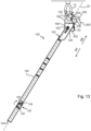
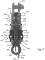
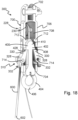
- a diagrammatic representation of an apparatus 500 is shown in figures 17 , 18 .
- the support unit 300 further comprises a tether 600 which extends from a free end 602 of the tether 600 (e.g. a user handling end) through the tether guide feature 228 in the shackle unit housing 706 to the shackle unit engagement feature 402 of the support member 400.
- a tether 600 which extends from a free end 602 of the tether 600 (e.g. a user handling end) through the tether guide feature 228 in the shackle unit housing 706 to the shackle unit engagement feature 402 of the support member 400.
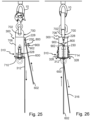
- the support unit 300 is operable to have a disengaged configuration (as shown in figures 15 , 17 , 18 , 19 , 20 , 25, 26 ) in which the support member 400 and the shackle unit 700 are disengaged (i.e. unlocked) from one another.
- a disengaged configuration as shown in figures 15 , 17 , 18 , 19 , 20 , 25, 26
- the support member 400 and the shackle unit 700 are disengaged (i.e. unlocked) from one another.
- the support member 400 is spaced apart from, and movable relative to, the shackle unit 700, albeit still connected by the tether 600.
- the support member 400 can be drawn towards the shackle unit 700 or drawn away from the shackle unit 700.
- anything attached to the support member 400 for example a hoist or other apparatus 500
- the support unit 300 is operable to have an engaged configuration in which the support member 400 is locked (e.g. fixed, coupled) to the shackle unit 700.
- the support member 400 and the shackle unit 700 are coupled together so that, with the shackle unit 700 coupled to, and hence supported from, an anchor 10, the support member 400 (and hence any apparatus 500 attached thereto) is likewise carried/supported by the anchor 10.
- the shackle unit housing 706 defines a support member receiving passage 708 having an opening 710 configured for receiving the support member 400 when the support unit 300 is in the engaged configuration. That is to say, the support member receiving passage 708 and the opening 710 may define the support member engagement feature 704 of the shackle unit 700.
- the guide feature 228 is configured such that when the support unit 300 is in the disengaged configuration and the free end 602 of the tether 600 is drawn away from the guide feature 228, the support member 400 is drawn into engagement with, and locked to, the shackle unit 700 such that the support unit 300 is in the engaged configuration.
- the guide feature 228 is configured such that when the free end 602 of the tether 600 is drawn away from the guide feature 228 when the support unit 300 is in the disengaged configuration, the support member 400 is drawn into engagement with, and locked to, the shackle unit 700 such that the support unit 300 is in the engaged configuration.
- the guide feature 228 may further comprise a roller 230, the tether 600 being engaged with the roller 230 so that the roller 230 rotates as the tether 600 is drawn past the roller 230.
- the support unit 300 may further comprise a locking mechanism 310.
- the locking mechanism 310 may comprise a locking lever 328 (e.g. a pawl) pivotably mounted on the shackle unit housing 706 and biased to pivot into, and hence extend into, the support member receiving passage 708.
- the locking mechanism 310 may further comprise a locking lever engagement feature 428 provided on the support member 400.
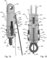
- the locking mechanism 310 is operable such that the locking lever 328 engages with the locking lever engagement feature 428 when the support member 400 extends sufficiently far along the support member receiving passage 708 to thereby prevent the support member 400 from being disengaged and removed from the shackle unit housing 706 (for example as shown in figure 16 ).
- the locking mechanism 310 may comprise two or more locking levers 328, spaced apart around the circumference of the shackle unit housing 706, each configured to operate in the same way and to engage with the locking lever engagement feature 428.
- the shackle unit engagement feature 402 may define the leading edge 410 of the support member 400, which extends from a point and increases in diameter along a part of the length of the support member 400 towards the apparatus coupling 404, and then reduces in diameter to define provide a shoulder 408 which defines the locking lever engagement feature 428.
- a stop feature 712 may be provided in the shackle unit housing 706 to engage with the support member 400 and is positioned such that it engages with the support member 400 when the support member 400 has travelled along the support member receiving passage 708 at least as far as is required to engage with the locking lever 328.
- the locking mechanism 310 may comprise a release mechanism 312 operable to pivot the (or each) locking lever 328 away from engagement with the locking lever engagement feature 428 provided on the support member 400.
- the locking lever 328 may be pivotably mounted to the shackle unit housing 706 at a pivot point 714.
- the release mechanism 312 comprises a release cable 316 which is looped round, and operable to act on, the second end part 332 of the locking lever 328.
- the release mechanism 312 is mounted and operable to act on the second end part 332 of the locking lever 328 to pivot the first end part 330 of the locking lever 328 away from engagement with the locking lever engagement feature 428 provided on the support member 400.
- the release cable 316 is mounted and operable to act on the second end part 332 of the locking lever 328 to pivot the first end part 330 of the locking lever 328 away from engagement with the locking lever engagement feature 428 provided on the support member 400.
- a brake unit 800 may be provided on the shackle unit housing 706 to engage with the tether 600.
- the tether guide feature 228, the brake unit 800 and the free end 602 of the tether 600 may be provided in series.
- the brake unit 800 is configured to engage with the tether 600 if tension in the tether 600 between the brake unit 800 and the free end 602 of the tether 600 is below a predetermined value and/or the free end 602 of the tether 600 is released.
- the brake unit 800 may be provided as a drop catch mechanism 900.
- the drop catch mechanism 900 may define a tapered passage 902 through which the tether 600 extends, and a catch member 904 (e.g. a wheel) mounted in, and moveable along, a slot 906 which extends along the tapered passage 902.
- the tether 600 is located between the catch member 904 and a wall 910 of the tapered passage 902.
- the drop catch mechanism 900 is configured such that if the tension in the tether 600 is sufficient to maintain a distance between the catch member 904 and the tether 600, then the tether 600 is free to travel past the catch member 904.
- the drop catch mechanism 900 is configured such that if the tension in the tether 600 is below a predetermined value and/or the free end 602 of the tether 600 is released, the tether 600 will engage with the catch member 904 to draw it along the tapered passage 902 with the tether 600 locked against the wall 910 of the drop catch mechanism 900 to thereby lock the tether 600 against the wall 910 of the drop catch mechanism 900. Hence if the tension in the tether 600 is below a predetermined value and/or the free end 602 of the tether 600 is released, the drop catch mechanism 900 will engage with the tether 600 to prevent the support member 400 from moving relative to the shackle unit 700.
- mount assembly 100 is first set to the first configuration (as shown in figure 9 ) such that the coupling member 122 is in the first position in which it is engageable with the engagement element 202 of the engagement unit (200), and the shuttle 126 is spaced apart from the recess 160.
- the lever handle 134 of the actuator controller 150 is in the first orientation (e.g. located in a mid position) such that full tension is not applied to either of the first control cable 136 or second control cable 138).
- the engagement unit 200 is then located in the cradle 106 (as shown in figure 10 ), with the mount assembly 100 still in the first configuration.
- the engagement element 202 e.g. wire 206 provided on the engagement unit 200 (e.g. hook) is coupled to the coupling member 122 of the coupling unit 120 (as shown in figure 10 ).
- the mount assembly 100 is then set to the second configuration (for example by movement of the shuttle 126 along the shuttle guide path 162 in the second direction D2) to thereby move the coupling member 122 in the first direction D1 to draw the engagement element 202 in the first direction D1 along the operational axis 20 towards the second end 104 and away from the first end 102 to thereby lock the engagement unit 200 against the cradle 106 and fix the latch 204 in the open configuration, and thereby engage the engagement unit 200 with the cradle 106 (as shown in figure 11 ).
- the locking member 128 of the shuttle 126 is engaged with the recess 160 and the coupling member 122 is then moved to the second position by use of the actuator 130.
- the locking member 128 being located in the recess 160 allows for second configuration to be carried out.
- the lever handle 134 of the actuator controller 150 is in the second orientation (rear facing as shown in figure 11 ) such that the respective control cable 136, 138 is in tension. Tension in the respective control cable 136, 138 may be maintained by the user by keeping hold of the actuator controller 150 through-out the operation. That is to say, moving the lever handle 134 of the actuator controller 150 to the second orientation causes the coupling member 122 to move to the second position and holds the engagement element 202 in tension, and thereby holds the engagement unit 200 against the cradle 106.
- a user may then lift the cradle 106, the coupling unit 120 and the engagement unit 200 up to where an anchor 10 is located and pass the anchor through the latch space (i.e. opening) on the engagement unit 200 to thereby mount the engagement unit 200 on the anchor 10.
- the mount assembly 100 is then set to the third configuration to release the engagement element 202 (e.g. wire 206) from the coupling member 122 to thereby release the engagement unit 200 (e.g. hook) from the cradle 106 and return the latch 204 to the closed configuration.
- the engagement element 202 e.g. wire 206
- the engagement unit 200 e.g. hook
- the mount assembly 100 is then set to the third configuration by use of the actuator 130. That is, the lever handle 134 of the actuator controller 150 is in the third orientation (i.e. in a release position, for example facing forwards as shown in figure 13 ) to release tension in the respective control cable 136, 138 and move the coupling member 122 in the second direction D2 along the operational axis 20 to the third position.
- the lever handle 134 of the actuator controller 150 is in the third orientation (i.e. in a release position, for example facing forwards as shown in figure 13 ) to release tension in the respective control cable 136, 138 and move the coupling member 122 in the second direction D2 along the operational axis 20 to the third position.
- the mount assembly 100 may then be moved away from the engagement unit 200, leaving the engagement unit 200 coupled to the anchor 10.
- the coupling member 122 For dismounting, the coupling member 122 is moved far enough toward the first end 102 to catch on the engagement element 202.
- the coupling member 122 is positioned on lower side of coupling unit 120 to improve visibility from ground level below.
- the cradle 106 can then be pushed against the rear of the engagement unit 200 to seat correctly into cradle 106. After this, full pressure can be applied through the actuator 130.
- the locking member 128 is located into recess 160. This will prevent unwanted movement of shuttle 126 when actuator 130 is operated. Dismounting is controlled entirely by the actuator 130, due to the first end 102 being at height.
- the support unit 300 may be operated as illustrated in figures 19 to 28 .
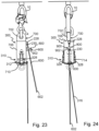
- Figures 19 , 21 , 23 , 25 , 27 show a first side view of the support unit 300
- figures 20 , 22 , 24 , 26 , 28 show a second side view of so the support unit 300.
- Figures 19, 20 show the support unit 300 in the disengaged configuration in which the support member 400 and the shackle unit 700 are disengaged from one another and spaced apart from one another.
- the shackle unit 700 is shown coupled to an engagement unit 200 (for example a hook) which is in turn coupled to an anchor 10.
- An apparatus 500 (for example a hoist) may be coupled to the apparatus coupling 404 of the support member 400.
- the tether 600 is pulled from the free end 602 so as to draw the tether 600 away from the guide feature 228 and thereby draw the support member 400 towards the shackle unit 700 (as shown in figures 21, 22 ).
- the support member 400 is drawn into the support member receiving passage 708.
- the leading edge 410 of the support member 400 passes the (or each) locking lever 328, which then engage with the locking lever engagement feature 428 provided on the support member 400 (as shown in figure 18 ).
- the locking mechanism 310 is operable such that the locking lever 328 engages with the locking lever engagement feature 428 when the support member 400 extends along (i.e. is drawn along) the support member receiving passage 708, to thereby prevent the support member 400 from being disengaged and removed from the shackle unit housing 706.
- the support member 400 is brought into engagement with, and locked to, the shackle unit 700 such that the support unit 300 is in the engaged configuration (as shown in figures 23, 24 ).
- any apparatus 500 connected to the support unit 300 may be operated as required.
- the release mechanism 312 of the locking mechanism 310 is operated to pivot the (or each) locking lever 328 away from engagement with the locking lever engagement feature 428 provided on the support member 400.
- This is achieved, as shown in figures 23, 24 , by drawing down the release cable 316 to act on the second end part 332 of the locking lever 328 to pivot the or each first end part 330 of the locking lever 328 away from engagement with the locking lever engagement feature 428 provided on the support member 400. It may be necessary to first lift the support member 400 relative to the shackle unit 700 by pulling on the tether 600 before pulling on the release cable 316 to pivot the or each locking lever 328.
- the support member 400 may then be lowered by a user allowing the tether 600 to be slackened and drawn back through the tether guide feature 228 so that the support member 400 may descend relative to the shackle unit 700 with any apparatus 500 attached thereto.
- the brake unit 800 is provided on the shackle unit housing 706 to engage with the tether 600, the brake unit 800 configured to engage with the tether 600 if tension in the tether 600 between the brake unit 800 and the free end 602 of the tether 600 drops below a predetermined value and/or the free end 602 of the tether 600 is released.
- apparatus which enables a user to support equipment from a high anchor point (for example at a height above themselves), or dis-engage equipment from a high anchor point, without needing to use a ladder, scaffolding, lifting platform or the like to get close to the anchor.
- the apparatus of the present disclosure also avoids, or at least minimises, the need for the user to personally support and/or carry the weight of the equipment during the mounting or disengagement process.
- the apparatus of the present disclosure allows the process of engaging a hook (i.e. the engagement unit 200, and any additional accessories/equipment coupled to the engagement unit 200 as desired/required, for example the support unit 300) with an anchor point 10 on a building or other support structure by one individual without the means for additional lifting equipment, or for the individual to be raised above the ground.
- a hook i.e. the engagement unit 200, and any additional accessories/equipment coupled to the engagement unit 200 as desired/required, for example the support unit 300
- the support unit 300 enables the process of supporting equipment (for example a hoist) from an anchor point 10 or demounting/disengaging the equipment from the anchor point 10 using the support unit 300, by an individual without the means for additional lifting equipment, or for the individual to be raised above the ground.
- supporting equipment for example a hoist
- the use of the mount assembly 100 and/or use of the support unit 300, whether used together or in combination, will reduce time, cost and risk associated with raising and securing equipment at height.
Landscapes
- Engineering & Computer Science (AREA)
- General Engineering & Computer Science (AREA)
- Mechanical Engineering (AREA)
- Lock And Its Accessories (AREA)
Abstract
A mount assembly (100) for carrying and positioning an engagement unit (200) of a support unit (300) on an anchor (10). The mount assembly comprises a cradle (106) for receiving the engagement unit (200), and a coupling unit (120) comprising a coupling member (122) for coupling with an engagement element (202) provided on the engagement unit (200). The mount assembly (100) has a first configuration and a second configuration. In the first configuration the coupling unit (120) is operable to receive the engagement unit (200) into the cradle (106) and the coupling member (122) is in a first position in which it is engageable with the engagement element (202) of the engagement unit (200). In the second configuration the coupling member (122) is in a second position spaced apart from the first position to thereby draw the engagement element (202) towards the second end (104) to thereby lock the engagement unit (200) against the cradle (106).
Description
- The present disclosure relates to a mount assembly.
- In particular the disclosure is concerned with a mount assembly for carrying and positioning an engagement unit of a support unit on an anchor.
- It is a requirement common to many industries to support and position heavy loads. For example, in manufacturing it may be necessary to lift parts of an assembly to move them into or out of position relative to another part of an assembly, for example to lift an engine from a vehicle body, or lift plates of metal from a delivery point to a machining station for it to be worked on.
- The equipment used to do the lifting may be a hoist of some kind. A hoist is a device used for lifting or lowering a load, which may be manually operated, electrically or pneumatically driven. The hoist may be connected to an anchor, for example a mounting point on another structure (e.g. a building or scaffolding), which by necessity must be higher than the article to be lifted. Commonly the anchor may be several metres above working height, and hence to mount the hoist to the anchor a ladder, scaffolding or cherry picker type device must be deployed so a user can reach the mount point. All of these options pose a problem for a user as they may introduce unnecessary risk, delay and expense to the mounting of the hoist to the anchor. Although this may be acceptable in processes where the hoist may occupy a fixed position for a long time, in other examples it may be necessary to frequently move the hoist position, for example in assembly plants of large and/or bespoke equipment. This may be because the hoist needs to be moved out of position while other equipment or assemblies are moved past it, or because the hoist is needed at a different workstation position. Hence it is required that the hoist can be disengaged from the anchor so it may be connected to a different anchor.
- Additionally, hoists are typically heavy pieces of equipment, so even if a user is able to use a ladder, scaffolding or cherry picker to get themselves into position, the act of carrying the hoist while connecting it to, or disconnecting it from, the anchor, may not be possible without putting a user at risk of injury.
- Hence apparatus which enables a user to mount equipment to a high anchor point (for example at a height above themselves), or dismount equipment from a high anchor point, without needing to use a ladder, scaffolding or cherry picker type device to get close to the anchor, and/or which avoids the need for the user to personally support or carry the weight of the equipment at any point in the mounting/dismounting process, is highly desirable.
- According to the present disclosure there is provided an apparatus, system and method as set forth in the appended claims. Other features of the invention will be apparent from the dependent claims, and the description which follows.
- Accordingly there may be provided a mount assembly (100) for carrying and positioning an engagement unit (200) of a support unit (300) on an anchor (10). The mount assembly (100) may extend between a first end (102) and a second end (104) along an operational axis (20), the first end (102) spaced apart from the second end (104) along the operational axis (20). A cradle (106) may be provided at the first end (102) for receiving the engagement unit (200). A coupling unit (120) comprising a coupling member (122) for coupling with an engagement element (202) may be provided on the engagement unit (200). The mount assembly (100) may have a first configuration and a second configuration. In the first configuration the coupling unit (120) may be operable to receive the engagement unit (200) into the cradle (106) and the coupling member (122) is in a first position in which it is engageable with the engagement element (202) of the engagement unit (200). In the second configuration the coupling member (122) may be in a second position spaced apart from the first position in a first direction (D1) along the operational axis (20) to thereby draw the engagement element (202) in the first direction (D1) along the operational axis (20) towards the second end (104) to thereby lock the engagement unit (200) against the cradle (106).
- The mount assembly (100) may have a third configuration in which the coupling unit (120) is operable to release the engagement unit (200) from the cradle (106) and the coupling member (122) is at a third position spaced apart from the first position in a second direction (D2) along the operational axis (20) such that the coupling unit (120) is dis-engageable from the engagement element (202) of the engagement unit (200), the first position being between the second position and the third position.
- The mount assembly (100) may further comprise an actuator (130), the actuator (130) configured to control the coupling unit (120) to switch between the different configurations.
- The coupling member (122) may be a hook member (124) configured for coupling with the engagement element (202) provided on the engagement unit (200).
- The mount assembly (100) may further comprise an arm (140) which extends from the coupling unit (120) towards the second end (104) along the operational axis (20).
- The mount assembly (100) may further comprise an actuator controller (150) provided on the arm (140), the actuator controller (150) operable to operate the actuator (130) to control the coupling unit (120) to switch between the different configurations.
- The arm (140) may be extendable and retractable.
- The actuator (130) may comprise a cable adjuster unit (132) and a lever handle (134) coupled to the cable adjuster unit (132). A first control cable (136) and a second control cable (138) may extend from the cable adjuster unit (132) to the coupling unit (120). The first control cable (136) and the second control cable (138) may be coupled to the coupling member (122) such that when the lever handle (134) is in a first orientation the mount assembly (100) is in the first configuration, when the lever handle (134) is in a second orientation the mount assembly (100) is in the second configuration, and when the lever handle (134) is in a third orientation the mount assembly (100) is in third configuration.
- The coupling member (122) may be mounted in the coupling unit (120) such that it is moveable along a predefined path along the operational axis (20) between the first position and the second position.
- The coupling member (122) may be mounted in the coupling unit (120) such that it is moveable along a predefined path along the operational axis (20) between the first position and the third position.
- The engagement unit (200) may comprise a latch (204) which has an open configuration and a closed configuration.
- The engagement element (202) of the engagement unit (200) may be a wire (206) which is coupled to the latch (204).
- The latch (204) may be configured such that when the mount assembly (100) is in the second configuration the latch (204) is in the open configuration to enable the engagement unit (200) to be engaged with the anchor (10) or to be dis-engaged from the anchor (10), and when the mount assembly (100) is in the third configuration the latch (204) is in the closed configuration to prevent the engagement unit (200) being dis-engaged with the anchor (10).
- The latch (204) may be biased to the closed configuration.
- The coupling unit (120) may comprise a shuttle (126) from which extends a locking member (128), the coupling unit (120) defining a recess (160) for locking engagement with the locking member (128). The shuttle (126) may be constrained to move along a guide path (162) in a direction parallel to the operational axis (20) towards and away from the recess (160). The locking member (128) may be being engageable with the recess (160). The shuttle (126) may be coupled to the coupling member (122) such that when the locking member (128) of the shuttle (126) is engaged with the recess (160) the coupling member (122) is operable to be moved to the second position. When the mount assembly (100) is in the first configuration, the shuttle (126) may be spaced apart from the recess (160) along the guide path (162).
- There may also be provided a method of operation of a mount assembly (100) according to the present disclosure comprising the steps of:
- setting the mount assembly (100) to the first configuration;
- locating the engagement unit (200) into the cradle (106);
- coupling the engagement element (202) provided on the engagement unit (200) with the coupling member (122);
- setting the mount assembly (100) to the second configuration to thereby draw the engagement element (202) in the first direction along the operational axis (20) towards the second end (104) to thereby:
- a. lock the engagement unit (200) against the cradle (106); and
- b. fix the latch (204) in the open configuration;
- engaging the engagement unit (200) with the anchor (10);
- setting the mount assembly (100) to the third configuration to release the engagement element (202) from the coupling member (122) to thereby:
- c. release the engagement unit (200) from the cradle (106); and
- d. return the latch (204) to the closed configuration.
- The method may further comprise the steps of the locking member (128) being engaged with the recess (160); and the coupling member (122) being moved to the second position.
- There may be provided a support unit (300) comprising a shackle unit (700) provided with an anchor coupling (702) for coupling with an anchor (10), a support member engagement feature (704), and a housing (706) which defines a tether guide feature (228).
- The support unit (300) may further comprise a support member (400) provided with a shackle unit engagement feature (402), and an apparatus coupling (404) configured for coupling with an apparatus (500) to be supported from the support unit (300).
- The support unit (300) may further comprise a tether (600) which extends from a free end (602) through the tether guide feature (228) through the shackle unit housing (706) to the support member (400).
- The support unit (300) operable to have a disengaged configuration in which the support member (400) and the shackle unit (700) are disengaged from one another; and an engaged configuration in which the support member (400) is locked to the shackle unit (700).
- The guide feature (228) may be configured such that when the support unit (300) is in the disengaged configuration and the free end (602) of the tether (600) is drawn away from the guide feature (228), the support member (400) is drawn into engagement with, and locked to, the shackle unit (700) such that the support unit (300) is in the engaged configuration.
- The guide feature (228) may further comprise a roller (230), the tether (600) engaged with the roller (230).
- The support member engagement feature (704) of the shackle unit housing (706) may be defined by a support member receiving passage (708) having an opening (710) configured for receiving the support member (400) when the support unit (300) is in the engaged configuration.
- The support unit (300) may further comprise a locking mechanism (310) which comprises: a locking lever (328) pivotably mounted on and biased to pivot into the support member receiving passage (708); a locking lever engagement feature (428) provided on the support member (400); the locking mechanism (310) operable such that the locking lever (328) engages with the locking lever engagement feature (428) when the support member (400) extends along the support member receiving passage (708) to thereby prevent the support member (400) from being disengaged and removed from the shackle unit housing (706).
- The shackle unit engagement feature (402) may define a leading edge (410) of the support member (400), which extends from a point and increases in diameter along a part of the length of the support member (400) towards the apparatus coupling (404), and then reduces in diameter to define provide a shoulder (408) which defines the locking lever engagement feature (428).
- A stop feature (712) may be provided in the shackle unit housing (706) to engage with the support member (400) and may be positioned such that it engages with the support member (400) when the support member (400) has travelled along the support member receiving passage (708) at least as far as is required to engage with the locking lever (328).
- The locking mechanism (310) may comprise a release mechanism (312) operable to pivot the locking lever (328) away from engagement with the locking lever engagement feature (428) provided on the support member (400).
- The locking lever (328) may be pivotably mounted to the shackle unit housing (706) at a pivot point (714). The locking lever (328) may comprise: a first end part (330), on one side of the pivot point (714), for engagement with the locking lever engagement feature (428) provided on the support member (400), and a second end part (332), on the other side of the pivot point (714), that extends radially outwards of the shackle unit housing (706), the release mechanism (312) being mounted and operable to act on the second end part (332) of the locking lever (328) to pivot the locking lever (328) away from engagement with the locking lever engagement feature (428) provided on the support member (400).
- A brake unit (800) may be provided on the shackle unit housing (706) to engage with the tether (600), the brake unit (800) configured to engage with the tether (600) if tension in the tether (600) between the brake unit (800) and the free end (602) of the tether (600) is below a predetermined value and/or the free end (602) of the tether (600) is released.
- The brake unit (800) may be provided as a drop catch mechanism (900) which defines: a tapered passage (902) through which the tether (600) extends; a catch member (904) mounted in, and moveable along, a slot (906) which extends along the tapered passage (902); the tether (600) being located between the catch member (904) and a wall (910) of the tapered passage (902); the drop catch mechanism (900) configured such that: if the tension in the tether (600) is sufficient to maintain a distance between the catch member (904) and the tether (600), then the tether (600) is free to travel past the catch member (904); and if the tension in the tether (600) is below a predetermined value and/or the free end (602) of the tether (600) is released, the tether (600) will engage with the catch member (904) to draw it along the tapered passage (902) with the tether (600) locked against the wall of the drop catch mechanism (900) to thereby lock the tether (600) against the wall (910) of the drop catch mechanism (900).
- The tether guide feature (228), the brake unit (800) and the free end (602) of the tether (600) may be provided in series.
- Hence there is provided apparatus which enables a user to mount equipment to a high anchor point (for example at a height above themselves), or dismount equipment from a high anchor point, without needing to use a ladder, scaffolding or cherry picker type device to get close to the anchor, and/or which avoids the need for the user to personally support or carry the weight of the equipment at any point in the mounting/dismounting process.
- Embodiments of the invention will now be described by way of example only with reference to the figures, in which:
-
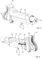
Figures 1, 2 show different views of part of a mount assembly according to the present disclosure when in a first configuration between a second configuration and a third configuration; -
Figures 3, 4 show different views of part of the mount assembly when in the second configuration; -
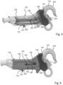
Figure 5 shows a side view of the part of the mount assembly shown infigures 1 to 4 in the second configuration, with part of the housing removed, and carrying an engagement unit of a support unit; -
Figure 6 shows the same view asfigure 5 with a complete housing; -
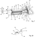
Figure 7 shows internal features of the part of the mount assembly shown infigures 1 to 6 in the third configuration; -
Figure 8 shows a further part of the mount assembly, not shown in infigures 1 to 7 ; -
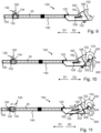
Figures 9 to 14 illustrate the method of operation of the mount assembly offigures 1 to 8 ; -
Figures 15 to 18 shows different views of a support unit according to the present disclosure; -
Figures 19, 20 ,figures 21, 22 ,figures 23, 24 ,figures 25, 26 andfigures 27, 28 illustrate the method of operation of the support unit shown infigures 15 to 18 ; and -
Figure 29 illustrates a part of the mount assembly. - The present disclosure relates to a
support unit 300 and mountassembly 100 for carrying and positioning anengagement unit 200 of asupport unit 300 on ananchor 10. -
Figures 1 to 14 illustrate amount assembly 100 for carrying and positioning anengagement unit 200 on ananchor 10. As illustrated in the figures, theengagement unit 200 may be provided as a hook. Theanchor 10 may be provided as any suitable coupling member to a support structure, an example of which is shown infigures 12 to 14 andfigures 19 to 28 as a ring. -
Figures 15 to 29 illustrate an example of asupport unit 300 which may be coupled to theengagement unit 200. Hence themount assembly 100 may be configured for carrying and positioning anengagement unit 200 of asupport unit 300 on ananchor 10. - An example of the
mount assembly 100 is shown infigures 9 to 14 . In this example themount assembly 100 extends between afirst end 102 and asecond end 104 along anoperational axis 20. Thefirst end 102 of themount assembly 100 is spaced apart from thesecond end 104 of themount assembly 100 along theoperational axis 20. - A cradle 106 (shown in detail in
figures 1 to 7 ) is provided at thefirst end 102 of themount assembly 100. Thecradle 106 is configured for receiving an engagement unit 200 (e.g. hook), as illustrated infigures 5, 6 andfigures 10 to 13 . - The
mount assembly 100 further comprises a coupling unit 120 (shown in detail infigures 1 to 7 ). In the example shown thecradle 106 is mounted to one end of thecoupling unit 120. That is to say, in the example shown, thecoupling unit 120 extends from thecradle 106 in a direction towards thesecond end 104 of themount assembly 100. - The
coupling unit 120 is provided with acoupling member 122 for coupling with anengagement element 202 provided on theengagement unit 200. In the example shown theengagement element 202 is provided as awire 206. In other examples, not shown, theengagement element 202 may be provided as an engagement feature of any suitable type for releasably coupling thecoupling unit 120 and theengagement unit 200. - As shown in the figures, the
coupling member 122 may be ahook member 124 configured for releasably coupling with the engagement element 202 (e.g. wire 206) provided on the engagement unit 200 (e.g. hook). - The
mount assembly 100 has a first configuration, a second configuration and a third configuration. - In the first configuration (as shown in
figures 1, 2 ,9, 10 , thecoupling unit 120 is operable to receive theengagement unit 200 into thecradle 106 and thecoupling member 122 is in a first position in which it is engageable with the engagement element 202 (e.g. wire 206) of the engagement unit 200 (e.g. hook). With the mount assembly in the first configuration (ie the coupling member in the first position) theengagement unit 200 may be fitted by hand to thecradle 106. - In the second configuration (as shown in
figures 3, 4 ,5, 6 ,11 ,12 ), thecoupling member 122 is in a second position. The second position is spaced apart from the first position in a first direction D1 along theoperational axis 20 to thereby draw the engagement element 202 (e.g. wire 206) in a direction along theoperational axis 20 towards thesecond end 104 of the mount assembly 100 (and hence away from thefirst end 102 of the mount assembly 100) to thereby lock the engagement unit 200 (e.g. hook) against thecradle 106. Hence the first direction D1 is in a direction away from thefirst end 102 towards thesecond end 104. - In the third configuration (as shown in
figures 7 ,13 ,14 ) thecoupling member 122 is at a third position spaced apart from the first position in a second direction D2 along theoperational axis 20 such that thecoupling unit 120 is dis-engageable from theengagement element 202 of theengagement unit 200. - The second direction D2 is in a direction away from the
second end 104 towards thefirst end 102. Hence the first position is between the second position and the third position. - Due to the position of the
coupling member 122 in the third configuration (as shown infigures 7 ,13 ,14 ) thecoupling unit 120 is operable to release theengagement unit 200 from thecradle 106 and thecoupling member 122. - The
coupling member 122 may be mounted in thecoupling unit 120 such that it is moveable along a predefined path along theoperational axis 20 between the first position and the second position. The predefined path along theoperational axis 20 may be linear. - The
coupling member 122 may be mounted in thecoupling unit 120 such that it is moveable along a predefined path along theoperational axis 20 between the first position and the third position. - As shown in
figures 5, 6 ,10 to 14 , theengagement unit 200 may comprise alatch 204 which has an open configuration and a closed configuration. That is to say, theengagement unit 200 comprises an opening, or latch space, which is spanned by thelatch 204 in the closed configuration. Thelatch 204 may be biased to the closed configuration, for example by a spring member. - As shown in the figures, the engagement element 202 (e.g. wire 206) of the engagement unit 200 (e.g. hook) may be coupled to the
latch 204. - The
latch 204 may be configured such that when themount assembly 100 is in the second configuration thelatch 204 is in the open configuration (as shown infigures 5, 6 ,11 ,12 ) to enable theengagement unit 200 to be engaged with theanchor 10 or to be dis-engaged from theanchor 10. - When the
mount assembly 100 is in the third configuration thelatch 204 is in the closed configuration (as shown infigures 10 ,13 ) to prevent theengagement unit 200 being dis-engaged with theanchor 10. - The
mount assembly 100 may further comprise anactuator 130. A part exploded view of anactuator 130 is shown infigure 8 , and as assembled infigures 9 to 14 . Theactuator 130 is configured to control thecoupling unit 120 so that thecoupling member 122 moves between the first position, the second position and the third position to switch themount assembly 100 between the first configuration, the second configuration and the third configuration. - As shown in part in
figure 8 , and in full infigures 9 to 14 , themount assembly 100 may further comprise anarm 140 which extends from thecoupling unit 120 towards thesecond end 104 of the mount assembly along theoperational axis 20. Thearm 140 may be extendable and retractable. That is to say, thearm 140 may be operable to increase and decrease in length along theoperational axis 20. Put another way, thearm 140 may be telescopic. - The
mount assembly 100 may further comprise anactuator controller 150 provided on thearm 140. Theactuator controller 150 may be provided towards thesecond end 104 of themount assembly 100. Theactuator controller 150 is operable to operate theactuator 130 to control thecoupling unit 120 to switch thecoupling member 122 between the first configuration, the second configuration and the third configuration. - The
actuator 130 may comprise acable adjuster unit 132 and alever handle 134 coupled to thecable adjuster unit 132. As illustrated in the examples offigures 7 ,8 , afirst control cable 136 and asecond control cable 138 extend from thecable adjuster unit 132 to thecoupling unit 120. - The
cable adjuster unit 132 may comprise aspool 142 coupled to thehandle 134. An end of thefirst control cable 136 and an end of thesecond control cable 138 are attached (for example by screw clamps) to thespool 142. Thefirst control cable 136 and thesecond control cable 138 are each provided in, and slideable relative to, asheath 135. Hence rotation of thespool 142 causes eachcontrol cable respective sheath 135. Thefirst control cable 136 and thesecond control cable 138 are mounted to thespool 142 in different locations (for example diametrically opposite one another across the diameter of the spool 142) such that rotation of thespool 142 in one direction (e.g. moving the lever handle 134 to a first orientation) will draw on thefirst control cable 136 back onto thespool 142 while urging thesecond control cable 138 off thespool 142, and such that that rotation of thespool 142 in an opposite direction (e.g. moving the lever handle 134 to a second orientation) will urge thefirst control cable 136 off thespool 142 while drawing thesecond control cable 138 onto thespool 142. By way of example, the first orientation of thelever handle 134 is shown infigures 9, 10 ,13 ,14 , and the second orientation of thelever 134 handle is shown infigures 11 ,12 . - As shown in
figure 3 , thefirst control cable 136 andsecond control cable 138 are coupled, directly or indirectly, to thecoupling member 122 such that when thelever handle 134 is in the first orientation themount assembly 100 is in the first configuration and thecoupling member 122 is in the first position, when thelever handle 134 is in the second orientation themount assembly 100 is in the second configuration and thecoupling member 122 in the second position, and when thelever handle 134 is in a third orientation themount assembly 100 is in third configuration and thecoupling member 122 is in the third position. - The
coupling unit 120 may comprise ahousing 129 which in which the moving parts of thecoupling unit 120 are retained. Infigures 3 ,5 part of thehousing 129 is shown removed to illustrate interior detail of thecoupling unit 120. - As shown in
figures 5 ,7 , thecoupling unit 120 comprises ashuttle 126 from which extends a lockingmember 128. Thefirst control cable 136 is fitted to afirst end 179 of theshuttle 126 and thesecond control cable 128 is fitted to asecond end 178 of theshuttle 126. Additionally thefirst control cable 136 is fitted to afirst end 182 of thecoupling member 122 and thesecond control cable 128 is fitted to asecond end 180 of thecoupling member 122. Hence theshuttle 126 is coupled to thecoupling member 122. - The
first control cable 136 extends through afirst passage 190 defined in thecoupling unit housing 129 to afirst roller 172, then to thefirst end 179 of theshuttle 126, then to asecond roller 176 and then to thefirst end 182 of thecoupling member 122. Thefirst control cable 136 is slideable relative to where it is coupled to thefirst end 179 of theshuttle 126. - The
second control cable 138 extends through asecond passage 192 defined in thecoupling unit housing 129 to athird roller 170, then to thesecond end 178 of theshuttle 126, then to afourth roller 174 and then to thesecond end 180 of thecoupling member 122. Thesecond control cable 138 is slideable relative to where it is coupled to thesecond end 178 of theshuttle 126. - The
first roller 172 and thesecond roller 176 are located towards thefirst end 102 of thecoupling unit housing 129, spaced apart from one another across theguide path 162. - The
third roller 170 and thefourth roller 174 are spaced apart fromfirst roller 172 and thesecond roller 176 in the first direction D1 along theguide path 162. Thethird roller 170 and thefourth roller 174 are spaced apart from one another across theguide path 162. - As shown in
figure 29 , the first end of 179 of theshuttle 126 may comprise afifth roller 118 which thefirst control cable 136 is engaged with, may move relative to along the surface of, and is trapped by to thereby couple theshuttle 126 to thefirst control cable 136. That is to say, thefirst control cable 136 may be threaded through a gap between theshuttle 126 and thefifth roller 118. - As shown in
figure 29 , the second end of 178 of theshuttle 126 may comprise asixth roller 116 which thesecond control cable 138 is engaged with, may move relative to along the surface of, and is trapped by to thereby couple theshuttle 126 to thesecond control cable 138. That is to say, thesecond control cable 138 may be threaded through a gap between theshuttle 126 and thesixth roller 116. - The routing of the
first control cable 136 and thesecond control cable 138 past their respective rollers and ends of theshuttle 126 is configured such that movement of thefirst control cable 136 and thesecond control cable 138 will result in the movement of thecoupling member 122 relative to thecoupling unit 120. - The routing of the
first control cable 136 and thesecond control cable 138 past their respective rollers and ends of theshuttle 126 is configured such that movement of theshuttle 126 will result in the movement of thecoupling member 122 relative to thecoupling unit 120. - Hence the
coupling member 122 may be moved from the first position to the second position by use of theactuator controller 150 to move thefirst control cable 136 and thesecond control cable 138 and/or by movement of theshuttle 126. - The
housing 129 defines arecess 160 for locking engagement with the lockingmember 128 of theshuttle 126. - In the example shown the
shuttle 126 is constrained to move along aguide path 162 in a direction parallel to theoperational axis 20 towards and away from therecess 160. the lockingmember 128 is engageable with the recess 160 (as shown infigures 6 ,7 ,11 ,12 ). The coupling of theshuttle 126 to thecoupling member 122 using thefirst control cable 136,second control cable 138 arrangement of rollers described above and shown in the figures is such that when the lockingmember 128 of theshuttle 126 is engaged with therecess 160 thecoupling member 122 is operable to be moved to the second position. - Hence the locking member (128) does not act to lock the
coupling member 122 in the second position, but allows for full loading to be applied through theactuator 130 via thecontrol cables - In the example shown the
guide path 162 is defined as aslot 164 in thehousing 129, and the lockingmember 128 may extend through theslot 164. Theguide path 162 is defined by thehousing 129. Theguide path 162 may be provided as a passage in which theshuttle 126 is located and is operable to move along. - The
shuttle 126 may be biased towards a position spaced apart from therecess 160 along theguide path 162, for example by a spring member. Theshuttle 126 may be biased towards a position in which thecoupling member 122 is in the first position and themount assembly 100 is in the first configuration. - When the
mount assembly 100 is in the first configuration, theshuttle 126 is spaced apart from therecess 160 along the guide path 162 (as shown infigures 1, 2 ),9, 10 ). - When the
mount assembly 100 is in the second configuration and the third configuration the lockingmember 128 of theshuttle 126 is located in therecess 160. During use, the lockingmember 128 is located in the recess by the user (e.g. by hand operation of the locking member 128). - An example of a
support unit 300 according to the present disclosure is shown infigures 13 to 26 . Thesupport unit 300 may be coupled to and/or comprise an engagement unit 200 (e.g. hook).
As shown infigures 13 to 26 , thesupport unit 300 may comprise ashackle unit 700. In the examples shown, theshackle unit 700 is coupled to theengagement unit 200. Theshackle unit 700 is provided with an anchor coupling 702 (e.g. a ring or hook) for coupling directly with ananchor 10 or, as shown in the examples, for coupling indirectly with ananchor 10 via anengagement unit 200. - The
shackle unit 700 is provided with a supportmember engagement feature 704. Theshackle unit 700 is further provided with ahousing 706 which defines atether guide feature 228. - The
shackle unit 700 further comprises asupport member 400. Thesupport member 400 may be provided as a mandrel. - The
support member 400 may be provided with an shackleunit engagement feature 402 which defines aleading edge 410 of thesupport member 400. Thesupport member 400 may further be provided with anapparatus coupling 404 which defines a trailingedge 406 of thesupport member 400. Theapparatus coupling 404 may be configured for coupling with anapparatus 500 to be supported from thesupport unit 300. For example theapparatus coupling 404 may be configured for coupling with anapparatus 500 to be supported from thesupport unit 300. A diagrammatic representation of anapparatus 500 is shown infigures 17 ,18 . - The
support unit 300 further comprises atether 600 which extends from afree end 602 of the tether 600 (e.g. a user handling end) through thetether guide feature 228 in theshackle unit housing 706 to the shackleunit engagement feature 402 of thesupport member 400. - The
support unit 300 is operable to have a disengaged configuration (as shown infigures 15 ,17 ,18 ,19 ,20 ,25, 26 ) in which thesupport member 400 and theshackle unit 700 are disengaged (i.e. unlocked) from one another. Hence in the disengaged configuration thesupport member 400 is spaced apart from, and movable relative to, theshackle unit 700, albeit still connected by thetether 600. Hence in the disengaged configuration thesupport member 400 can be drawn towards theshackle unit 700 or drawn away from theshackle unit 700. Hence in the disengaged configuration anything attached to the support member 400 (for example a hoist or other apparatus 500) can be raised up to, or lowered down from, where theshackle unit 700 is mounted from ananchor 10 using thetether 600. - The
support unit 300 is operable to have an engaged configuration in which thesupport member 400 is locked (e.g. fixed, coupled) to theshackle unit 700. - Hence in the engaged configuration the
support member 400 and theshackle unit 700 are coupled together so that, with theshackle unit 700 coupled to, and hence supported from, ananchor 10, the support member 400 (and hence anyapparatus 500 attached thereto) is likewise carried/supported by theanchor 10. - The
shackle unit housing 706 defines a supportmember receiving passage 708 having anopening 710 configured for receiving thesupport member 400 when thesupport unit 300 is in the engaged configuration. That is to say, the supportmember receiving passage 708 and theopening 710 may define the supportmember engagement feature 704 of theshackle unit 700. - The
guide feature 228 is configured such that when thesupport unit 300 is in the disengaged configuration and thefree end 602 of thetether 600 is drawn away from theguide feature 228, thesupport member 400 is drawn into engagement with, and locked to, theshackle unit 700 such that thesupport unit 300 is in the engaged configuration. - That is to say, the
guide feature 228 is configured such that when thefree end 602 of thetether 600 is drawn away from theguide feature 228 when thesupport unit 300 is in the disengaged configuration, thesupport member 400 is drawn into engagement with, and locked to, theshackle unit 700 such that thesupport unit 300 is in the engaged configuration. - The
guide feature 228 may further comprise aroller 230, thetether 600 being engaged with theroller 230 so that theroller 230 rotates as thetether 600 is drawn past theroller 230. - As best shown in
figures 13 to 16 , thesupport unit 300 may further comprise alocking mechanism 310. Thelocking mechanism 310 may comprise a locking lever 328 (e.g. a pawl) pivotably mounted on theshackle unit housing 706 and biased to pivot into, and hence extend into, the supportmember receiving passage 708. Thelocking mechanism 310 may further comprise a lockinglever engagement feature 428 provided on thesupport member 400. - The
locking mechanism 310 is operable such that the lockinglever 328 engages with the lockinglever engagement feature 428 when thesupport member 400 extends sufficiently far along the supportmember receiving passage 708 to thereby prevent thesupport member 400 from being disengaged and removed from the shackle unit housing 706 (for example as shown infigure 16 ). - The
locking mechanism 310 may comprise two or more locking levers 328, spaced apart around the circumference of theshackle unit housing 706, each configured to operate in the same way and to engage with the lockinglever engagement feature 428. - The shackle
unit engagement feature 402 may define theleading edge 410 of thesupport member 400, which extends from a point and increases in diameter along a part of the length of thesupport member 400 towards theapparatus coupling 404, and then reduces in diameter to define provide ashoulder 408 which defines the lockinglever engagement feature 428. - A
stop feature 712 may be provided in theshackle unit housing 706 to engage with thesupport member 400 and is positioned such that it engages with thesupport member 400 when thesupport member 400 has travelled along the supportmember receiving passage 708 at least as far as is required to engage with the lockinglever 328. - The
locking mechanism 310 may comprise arelease mechanism 312 operable to pivot the (or each) lockinglever 328 away from engagement with the lockinglever engagement feature 428 provided on thesupport member 400. - As shown in the figures, the locking
lever 328 may be pivotably mounted to theshackle unit housing 706 at apivot point 714. Afirst end part 330 of the lockinglever 328, on one side of thepivot point 714, is provided for engagement with the lockinglever engagement feature 428 provided on thesupport member 400. Asecond end part 332 of the lockinglever 328, on the other side of thepivot point 714, extends radially outwards of theshackle unit housing 706. - In the example shown in the figures the
release mechanism 312 comprises arelease cable 316 which is looped round, and operable to act on, thesecond end part 332 of the lockinglever 328. Hence therelease mechanism 312 is mounted and operable to act on thesecond end part 332 of the lockinglever 328 to pivot thefirst end part 330 of the lockinglever 328 away from engagement with the lockinglever engagement feature 428 provided on thesupport member 400. Put another way, therelease cable 316 is mounted and operable to act on thesecond end part 332 of the lockinglever 328 to pivot thefirst end part 330 of the lockinglever 328 away from engagement with the lockinglever engagement feature 428 provided on thesupport member 400. - As shown in
figures 13 ,14 andfigures 17 to 26 , abrake unit 800 may be provided on theshackle unit housing 706 to engage with thetether 600. - As shown in the figures, the
tether guide feature 228, thebrake unit 800 and thefree end 602 of thetether 600 may be provided in series. - The
brake unit 800 is configured to engage with thetether 600 if tension in thetether 600 between thebrake unit 800 and thefree end 602 of thetether 600 is below a predetermined value and/or thefree end 602 of thetether 600 is released. - The
brake unit 800 may be provided as adrop catch mechanism 900. Thedrop catch mechanism 900 may define atapered passage 902 through which thetether 600 extends, and a catch member 904 (e.g. a wheel) mounted in, and moveable along, aslot 906 which extends along thetapered passage 902. Thetether 600 is located between thecatch member 904 and a wall 910 of thetapered passage 902. - The
drop catch mechanism 900 is configured such that if the tension in thetether 600 is sufficient to maintain a distance between thecatch member 904 and thetether 600, then thetether 600 is free to travel past thecatch member 904. - The
drop catch mechanism 900 is configured such that if the tension in thetether 600 is below a predetermined value and/or thefree end 602 of thetether 600 is released, thetether 600 will engage with thecatch member 904 to draw it along thetapered passage 902 with thetether 600 locked against the wall 910 of thedrop catch mechanism 900 to thereby lock thetether 600 against the wall 910 of thedrop catch mechanism 900. Hence if the tension in thetether 600 is below a predetermined value and/or thefree end 602 of thetether 600 is released, thedrop catch mechanism 900 will engage with thetether 600 to prevent thesupport member 400 from moving relative to theshackle unit 700. - There may be provided a method of positioning an
engagement unit 200 of asupport unit 300 on ananchor 10 using amount assembly 100 according to the present disclosure. There may be provided a method of operation of amount assembly 100 according to the present disclosure. In these methods, themount assembly 100 is first set to the first configuration (as shown infigure 9 ) such that thecoupling member 122 is in the first position in which it is engageable with theengagement element 202 of the engagement unit (200), and theshuttle 126 is spaced apart from therecess 160. The lever handle 134 of theactuator controller 150 is in the first orientation (e.g. located in a mid position) such that full tension is not applied to either of thefirst control cable 136 or second control cable 138). - The
engagement unit 200 is then located in the cradle 106 (as shown infigure 10 ), with themount assembly 100 still in the first configuration. The engagement element 202 (e.g. wire 206) provided on the engagement unit 200 (e.g. hook) is coupled to thecoupling member 122 of the coupling unit 120 (as shown infigure 10 ). - The
mount assembly 100 is then set to the second configuration (for example by movement of theshuttle 126 along theshuttle guide path 162 in the second direction D2) to thereby move thecoupling member 122 in the first direction D1 to draw theengagement element 202 in the first direction D1 along theoperational axis 20 towards thesecond end 104 and away from thefirst end 102 to thereby lock theengagement unit 200 against thecradle 106 and fix thelatch 204 in the open configuration, and thereby engage theengagement unit 200 with the cradle 106 (as shown infigure 11 ). The lockingmember 128 of theshuttle 126 is engaged with therecess 160 and thecoupling member 122 is then moved to the second position by use of theactuator 130. Hence the lockingmember 128 being located in therecess 160 allows for second configuration to be carried out. To achieve the second configuration, the lever handle 134 of theactuator controller 150 is in the second orientation (rear facing as shown infigure 11 ) such that therespective control cable respective control cable actuator controller 150 through-out the operation. That is to say, moving the lever handle 134 of theactuator controller 150 to the second orientation causes thecoupling member 122 to move to the second position and holds theengagement element 202 in tension, and thereby holds theengagement unit 200 against thecradle 106. - As shown in
figure 12 , using the arm 140 a user may then lift thecradle 106, thecoupling unit 120 and theengagement unit 200 up to where ananchor 10 is located and pass the anchor through the latch space (i.e. opening) on theengagement unit 200 to thereby mount theengagement unit 200 on theanchor 10. - As shown in
figure 13 , themount assembly 100 is then set to the third configuration to release the engagement element 202 (e.g. wire 206) from thecoupling member 122 to thereby release the engagement unit 200 (e.g. hook) from thecradle 106 and return thelatch 204 to the closed configuration. - That is the
mount assembly 100 is then set to the third configuration by use of theactuator 130. That is, the lever handle 134 of theactuator controller 150 is in the third orientation (i.e. in a release position, for example facing forwards as shown infigure 13 ) to release tension in therespective control cable coupling member 122 in the second direction D2 along theoperational axis 20 to the third position. - The
mount assembly 100 may then be moved away from theengagement unit 200, leaving theengagement unit 200 coupled to theanchor 10. - For dismounting, the
coupling member 122 is moved far enough toward thefirst end 102 to catch on theengagement element 202. Thecoupling member 122 is positioned on lower side ofcoupling unit 120 to improve visibility from ground level below. When theengagement element 202 has been captured, thecradle 106 can then be pushed against the rear of theengagement unit 200 to seat correctly intocradle 106. After this, full pressure can be applied through theactuator 130. Before offeringcoupling unit 120 up toengagement unit 200 and dismounting is carried out, the lockingmember 128 is located intorecess 160. This will prevent unwanted movement ofshuttle 126 whenactuator 130 is operated. Dismounting is controlled entirely by theactuator 130, due to thefirst end 102 being at height. - The
support unit 300 may be operated as illustrated infigures 19 to 28 .Figures 19 ,21 ,23 ,25 ,27 show a first side view of thesupport unit 300, andfigures 20 ,22 ,24 ,26 ,28 show a second side view of so thesupport unit 300. -
Figures 19, 20 show thesupport unit 300 in the disengaged configuration in which thesupport member 400 and theshackle unit 700 are disengaged from one another and spaced apart from one another. Theshackle unit 700 is shown coupled to an engagement unit 200 (for example a hook) which is in turn coupled to ananchor 10. - An apparatus 500 (for example a hoist) may be coupled to the
apparatus coupling 404 of thesupport member 400. - To bring the
support member 400 into engagement with theshackle unit 700, thetether 600 is pulled from thefree end 602 so as to draw thetether 600 away from theguide feature 228 and thereby draw thesupport member 400 towards the shackle unit 700 (as shown infigures 21, 22 ). - The
support member 400 is drawn into the supportmember receiving passage 708. As thesupport member 400 is drawn along the support member receiving passage 708 (as shown infigure 17 ), theleading edge 410 of thesupport member 400 passes the (or each) lockinglever 328, which then engage with the lockinglever engagement feature 428 provided on the support member 400 (as shown infigure 18 ). That is to say, thelocking mechanism 310 is operable such that the lockinglever 328 engages with the lockinglever engagement feature 428 when thesupport member 400 extends along (i.e. is drawn along) the supportmember receiving passage 708, to thereby prevent thesupport member 400 from being disengaged and removed from theshackle unit housing 706. In this way thesupport member 400 is brought into engagement with, and locked to, theshackle unit 700 such that thesupport unit 300 is in the engaged configuration (as shown infigures 23, 24 ). - When in the engaged configuration any
apparatus 500 connected to thesupport unit 300 may be operated as required. - When it is required to lower the support member 400 (for example to lower the apparatus 500), then the
release mechanism 312 of thelocking mechanism 310 is operated to pivot the (or each) lockinglever 328 away from engagement with the lockinglever engagement feature 428 provided on thesupport member 400. This is achieved, as shown infigures 23, 24 , by drawing down therelease cable 316 to act on thesecond end part 332 of the lockinglever 328 to pivot the or eachfirst end part 330 of the lockinglever 328 away from engagement with the lockinglever engagement feature 428 provided on thesupport member 400. It may be necessary to first lift thesupport member 400 relative to theshackle unit 700 by pulling on thetether 600 before pulling on therelease cable 316 to pivot the or each lockinglever 328. - As shown in
figures 27, 28 , thesupport member 400 may then be lowered by a user allowing thetether 600 to be slackened and drawn back through thetether guide feature 228 so that thesupport member 400 may descend relative to theshackle unit 700 with anyapparatus 500 attached thereto. - In an example where present, the
brake unit 800 is provided on theshackle unit housing 706 to engage with thetether 600, thebrake unit 800 configured to engage with thetether 600 if tension in thetether 600 between thebrake unit 800 and thefree end 602 of thetether 600 drops below a predetermined value and/or thefree end 602 of thetether 600 is released. - Hence there is provided apparatus which enables a user to support equipment from a high anchor point (for example at a height above themselves), or dis-engage equipment from a high anchor point, without needing to use a ladder, scaffolding, lifting platform or the like to get close to the anchor. The apparatus of the present disclosure also avoids, or at least minimises, the need for the user to personally support and/or carry the weight of the equipment during the mounting or disengagement process.
- The apparatus of the present disclosure allows the process of engaging a hook (i.e. the
engagement unit 200, and any additional accessories/equipment coupled to theengagement unit 200 as desired/required, for example the support unit 300) with ananchor point 10 on a building or other support structure by one individual without the means for additional lifting equipment, or for the individual to be raised above the ground. - In an example in which the
support unit 300 is coupled to theengagement unit 200, thesupport unit 300 enables the process of supporting equipment (for example a hoist) from ananchor point 10 or demounting/disengaging the equipment from theanchor point 10 using thesupport unit 300, by an individual without the means for additional lifting equipment, or for the individual to be raised above the ground. - Hence the use of the
mount assembly 100 and/or use of thesupport unit 300, whether used together or in combination, will reduce time, cost and risk associated with raising and securing equipment at height. - Attention is directed to all papers and documents which are filed concurrently with or previous to this specification in connection with this application and which are open to public inspection with this specification, and the contents of all such papers and documents are incorporated herein by reference.
- All of the features disclosed in this specification (including any accompanying claims, abstract and drawings), and/or all of the steps of any method or process so disclosed, may be combined in any combination, except combinations where at least some of such features and/or steps are mutually exclusive.
- Each feature disclosed in this specification (including any accompanying claims, abstract and drawings) may be replaced by alternative features serving the same, equivalent or similar purpose, unless expressly stated otherwise. Thus, unless expressly stated otherwise, each feature disclosed is one example only of a generic series of equivalent or similar features.
- The invention is not restricted to the details of the foregoing embodiment(s). The invention extends to any novel one, or any novel combination, of the features disclosed in this specification (including any accompanying claims, abstract and drawings), or to any novel one, or any novel combination, of the steps of any method or process so disclosed.
Claims (14)
- A mount assembly (100) for carrying and positioning an engagement unit (200) of a support unit (300) on an anchor (10), the mount assembly (100) extending between a first end (102) and a second end (104) along an operational axis (20), the first end (102) spaced apart from the second end (104) along the operational axis (20);a cradle (106) provided at the first end (102) for receiving the engagement unit (200); anda coupling unit (120) comprising a coupling member (122) for coupling with an engagement element (202) provided on the engagement unit (200),the mount assembly (100) having a first configuration and a second configuration, wherein:in the first configuration the coupling unit (120) is operable to receive the engagement unit (200) into the cradle (106) and the coupling member (122) is in a first position in which it is engageable with the engagement element (202) of the engagement unit (200), andin the second configuration the coupling member (122) is in a second position spaced apart from the first position in a first direction (D1) along the operational axis (20) to thereby draw the engagement element (202) in the first direction (D1) along the operational axis (20) towards the second end (104) to thereby lock the engagement unit (200) against the cradle (106).
- . A mount assembly (100) as claimed in claim 1 wherein the mount assembly (100) has a third configuration in which the coupling unit (120) is operable to release the engagement unit (200) from the cradle (106) and the coupling member (122) is at a third position spaced apart from the first position in a second direction (D2) along the operational axis (20) such that the coupling unit (120) is dis-engageable from the engagement element (202) of the engagement unit (200), the first position being between the second position and the third position.
- A mount assembly (100) as claimed in claim 1 or claim 2 further comprising an actuator (130), the actuator (130) configured to control the coupling unit (120) to switch between the different configurations.
- A mount assembly (100) as claimed in any one of the preceding claims wherein the coupling member (122) is a hook member (124) configured for coupling with the engagement element (202) provided on the engagement unit (200).
- A mount assembly (100) as claimed in any one of the preceding claims further comprising an arm (140) which extends from the coupling unit (120) towards the second end (104) along the operational axis (20), and the mount assembly (100) further comprises an actuator controller (150) provided on the arm (140), the actuator controller (150) operable to operate the actuator (130) to control the coupling unit (120) to switch between the different configurations.
- A mount assembly (100) as claimed in claim 5 wherein the arm (140) is extendable and retractable.
- A mount assembly (100) as claimed in any one of claims 3 to 6 wherein:the actuator (130) comprises a cable adjuster unit (132) and a lever handle (134) coupled to the cable adjuster unit (132);a first control cable (136) and a second control cable (138) extend from the cable adjuster unit (132) to the coupling unit (120),the first control cable (136) and the second control cable (138) being coupled to the coupling member (122) such that when the lever handle (134) is in a first orientation the mount assembly (100) is in the first configuration, when the lever handle (134) is in a second orientation the mount assembly (100) is in the second configuration, and when the lever handle (134) is in a third orientation the mount assembly (100) is in third configuration.
- A mount assembly (100) in any one of the preceding claims wherein the coupling member (122) is mounted in the coupling unit (120) such that it is moveable along a predefined path along the operational axis (20) between the first position and the second position.
- A mount assembly (100) in any one of claims 2 to 8 wherein the coupling member (122) is mounted in the coupling unit (120) such that it is moveable along a predefined path along the operational axis (20) between the first position and the third position.
- A mount assembly (100) as claimed in any one of the preceding claims wherein:the engagement unit (200) comprises a latch (204) which has an open configuration and a closed configuration;the engagement element (202) of the engagement unit (200) is a wire (206) which is coupled to the latch (204);the latch (204) configured such that when the mount assembly (100) is in the second configuration the latch (204) is in the open configuration to enable the engagement unit (200) to be engaged with the anchor (10) or to be dis-engaged from the anchor (10), andwhen the mount assembly (100) is in the third configuration the latch (204) is in the closed configuration to prevent the engagement unit (200) being dis-engaged with the anchor (10).
- A mount assembly (100) as claimed in claim 10 wherein the latch (204) is biased to the closed configuration.
- A mount assembly (100) as claimed in any one of claims 1 to 11 wherein:
the coupling unit (120) comprises a shuttle (126) from which extends a locking member (128),the coupling unit (120) defining a recess (160) for locking engagement with the locking member (128);the shuttle (126) being constrained to move along a guide path (162) in a direction parallel to the operational axis (20) towards and away from the recess (160);the locking member (128) being engageable with the recess (160). andthe shuttle (126) being coupled to the coupling member (122) such that when the locking member (128) of the shuttle (126) is engaged with the recess (160) the coupling member (122) is operable to be moved to the second position; andwhen the mount assembly (100) is in the first configuration, the shuttle (126) is spaced apart from the recess (160) along the guide path (162). - A method of operation of a mount assembly (100) as claimed in claim 11 or claim 12, comprising the steps of:setting the mount assembly (100) to the first configuration;locating the engagement unit (200) into the cradle (106);coupling the engagement element (202) provided on the engagement unit (200) with the coupling member (122);setting the mount assembly (100) to the second configuration to thereby draw the engagement element (202) in the first direction along the operational axis (20) towards the second end (104) to thereby:a. lock the engagement unit (200) against the cradle (106); andb. fix the latch (204) in the open configuration;engaging the engagement unit (200) with the anchor (10);setting the mount assembly (100) to the third configuration to release the engagement element (202) from the coupling member (122) to thereby:c. release the engagement unit (200) from the cradle (106); andd. return the latch (204) to the closed configuration.
- A method as claimed in claim 13 when dependent on claim 11 further comprising the steps of:the locking member (128) being engaged with the recess (160); andthe coupling member (122) being moved to the second position.
Priority Applications (4)
| Application Number | Priority Date | Filing Date | Title |
|---|---|---|---|
| EP23182124.0A EP4484793A1 (en) | 2023-06-28 | 2023-06-28 | Mount assembly |
| PCT/GB2024/051377 WO2025003626A1 (en) | 2023-06-28 | 2024-05-29 | Mount assembly |
| AU2024310838A AU2024310838A1 (en) | 2023-06-28 | 2024-05-29 | Mount assembly |
| EP24730754.9A EP4735775A1 (en) | 2023-06-28 | 2024-05-29 | Mount assembly |
Applications Claiming Priority (1)
| Application Number | Priority Date | Filing Date | Title |
|---|---|---|---|
| EP23182124.0A EP4484793A1 (en) | 2023-06-28 | 2023-06-28 | Mount assembly |
Publications (1)
| Publication Number | Publication Date |
|---|---|
| EP4484793A1 true EP4484793A1 (en) | 2025-01-01 |
Family
ID=87036282
Family Applications (1)
| Application Number | Title | Priority Date | Filing Date |
|---|---|---|---|
| EP23182124.0A Ceased EP4484793A1 (en) | 2023-06-28 | 2023-06-28 | Mount assembly |
Country Status (1)
| Country | Link |
|---|---|
| EP (1) | EP4484793A1 (en) |
Citations (3)
| Publication number | Priority date | Publication date | Assignee | Title |
|---|---|---|---|---|
| US4644617A (en) * | 1982-09-28 | 1987-02-24 | Tupper Alan W | Releasable locking coupling or support device |
| US20120284997A1 (en) * | 2011-05-12 | 2012-11-15 | Cantega Technologies Inc. | Tool and method for handling a part |
| US8939481B1 (en) * | 2014-05-19 | 2015-01-27 | Lai Qi | Animal waste handling system |
-
2023
- 2023-06-28 EP EP23182124.0A patent/EP4484793A1/en not_active Ceased
Patent Citations (3)
| Publication number | Priority date | Publication date | Assignee | Title |
|---|---|---|---|---|
| US4644617A (en) * | 1982-09-28 | 1987-02-24 | Tupper Alan W | Releasable locking coupling or support device |
| US20120284997A1 (en) * | 2011-05-12 | 2012-11-15 | Cantega Technologies Inc. | Tool and method for handling a part |
| US8939481B1 (en) * | 2014-05-19 | 2015-01-27 | Lai Qi | Animal waste handling system |
Similar Documents
| Publication | Publication Date | Title |
|---|---|---|
| CN104876122B (en) | Airborne ballasting system, jumbo part and the method for removably installing ballast | |
| US8684335B2 (en) | Portable hoist for hand trucks | |
| EP3594131B1 (en) | Rotational tray assembly | |
| JP7535580B2 (en) | Fall Protection System | |
| EP3040272A1 (en) | Conformal manually operated aircraft cargo restraint mechanism with integrated tie off | |
| US3278045A (en) | Counterweight support mechanism | |
| CN116260069A (en) | A device, system and method for hanging and removing grounding wires | |
| EP4334171B1 (en) | A device for supporting and operating a cable drum and a service trailer comprising said device | |
| JP7653987B2 (en) | Fall Protection System | |
| EP4484355A1 (en) | Support unit | |
| BR112021006870A2 (en) | installation trailer for coiled hose and method of using it | |
| AU2024310838A1 (en) | Mount assembly | |
| AU2024306874A1 (en) | Support unit | |
| WO2013138842A1 (en) | Tow hitch with movable coupling | |
| GB2631395A (en) | Mount assembly | |
| GB2631396A (en) | Support unit | |
| CN108529454B (en) | Boom coupling system for boom storage | |
| EP3197808B1 (en) | Reel drive assembly | |
| US1971498A (en) | Counterbalance and loading and unloading device therefor | |
| US11072440B2 (en) | Apparatus for supporting an aircraft component adjacent to an aircraft and a method for the same | |
| US20220363324A1 (en) | Apparatus and method for stowing and deploying a vehicle tire | |
| CN115043269A (en) | Mobile cable winding and unwinding system and method | |
| CN211033510U (en) | Handling device for processing equipment | |
| CN121626837B (en) | Disassembly device and disassembly method for fusion device maintenance window | |
| US7182318B1 (en) | Method and apparatus for removing and installing a differential of a vehicle |
Legal Events
| Date | Code | Title | Description |
|---|---|---|---|
| PUAI | Public reference made under article 153(3) epc to a published international application that has entered the european phase |
Free format text: ORIGINAL CODE: 0009012 |
|
| STAA | Information on the status of an ep patent application or granted ep patent |
Free format text: STATUS: THE APPLICATION HAS BEEN PUBLISHED |
|
| AK | Designated contracting states |
Kind code of ref document: A1 Designated state(s): AL AT BE BG CH CY CZ DE DK EE ES FI FR GB GR HR HU IE IS IT LI LT LU LV MC ME MK MT NL NO PL PT RO RS SE SI SK SM TR |
|
| STAA | Information on the status of an ep patent application or granted ep patent |
Free format text: STATUS: THE APPLICATION HAS BEEN REFUSED |
|
| 18R | Application refused |
Effective date: 20250115 |