CN116260069A - Grounding wire hanging and detaching device, system and method - Google Patents
Grounding wire hanging and detaching device, system and method Download PDFInfo
- Publication number
- CN116260069A CN116260069A CN202211346985.4A CN202211346985A CN116260069A CN 116260069 A CN116260069 A CN 116260069A CN 202211346985 A CN202211346985 A CN 202211346985A CN 116260069 A CN116260069 A CN 116260069A
- Authority
- CN
- China
- Prior art keywords
- wire
- ground wire
- clamping
- ground
- assembly
- Prior art date
- Legal status (The legal status is an assumption and is not a legal conclusion. Google has not performed a legal analysis and makes no representation as to the accuracy of the status listed.)
- Pending
Links
- 238000000034 method Methods 0.000 title claims abstract description 32
- 210000000080 chela (arthropods) Anatomy 0.000 claims description 29
- 230000009471 action Effects 0.000 claims description 24
- 230000000903 blocking effect Effects 0.000 claims description 15
- 230000005484 gravity Effects 0.000 claims description 9
- 230000009194 climbing Effects 0.000 claims description 7
- 238000007789 sealing Methods 0.000 claims description 4
- 230000006698 induction Effects 0.000 abstract description 3
- 230000008569 process Effects 0.000 abstract description 2
- 238000010586 diagram Methods 0.000 description 10
- 206010014357 Electric shock Diseases 0.000 description 4
- 238000010276 construction Methods 0.000 description 4
- 230000033001 locomotion Effects 0.000 description 4
- 238000005096 rolling process Methods 0.000 description 3
- 208000027418 Wounds and injury Diseases 0.000 description 2
- 230000008901 benefit Effects 0.000 description 2
- 238000012986 modification Methods 0.000 description 2
- 230000004048 modification Effects 0.000 description 2
- 230000004044 response Effects 0.000 description 2
- 238000000926 separation method Methods 0.000 description 2
- 239000007787 solid Substances 0.000 description 2
- 238000004804 winding Methods 0.000 description 2
- 229910000831 Steel Inorganic materials 0.000 description 1
- 230000004075 alteration Effects 0.000 description 1
- 230000005540 biological transmission Effects 0.000 description 1
- 210000000078 claw Anatomy 0.000 description 1
- 238000004891 communication Methods 0.000 description 1
- 230000006378 damage Effects 0.000 description 1
- 208000014674 injury Diseases 0.000 description 1
- 230000001788 irregular Effects 0.000 description 1
- 238000010030 laminating Methods 0.000 description 1
- 239000010959 steel Substances 0.000 description 1
Images


Classifications
-
- H—ELECTRICITY
- H02—GENERATION; CONVERSION OR DISTRIBUTION OF ELECTRIC POWER
- H02G—INSTALLATION OF ELECTRIC CABLES OR LINES, OR OF COMBINED OPTICAL AND ELECTRIC CABLES OR LINES
- H02G1/00—Methods or apparatus specially adapted for installing, maintaining, repairing or dismantling electric cables or lines
- H02G1/02—Methods or apparatus specially adapted for installing, maintaining, repairing or dismantling electric cables or lines for overhead lines or cables
- H02G1/04—Methods or apparatus specially adapted for installing, maintaining, repairing or dismantling electric cables or lines for overhead lines or cables for mounting or stretching
-
- H—ELECTRICITY
- H02—GENERATION; CONVERSION OR DISTRIBUTION OF ELECTRIC POWER
- H02G—INSTALLATION OF ELECTRIC CABLES OR LINES, OR OF COMBINED OPTICAL AND ELECTRIC CABLES OR LINES
- H02G7/00—Overhead installations of electric lines or cables
- H02G7/05—Suspension arrangements or devices for electric cables or lines
- H02G7/06—Suspensions for lines or cables along a separate supporting wire, e.g. S-hook
- H02G7/08—Members clamped to the supporting wire or to the line or cable
Landscapes
- Load-Engaging Elements For Cranes (AREA)
Abstract
The invention provides a grounding wire hanging and detaching device, a grounding wire hanging and detaching system and a grounding wire hanging and detaching method. The device comprises: the wire clamping assembly and the ground wire dismantling and fixing assembly; wherein, the ground wire is torn down and is fixed the subassembly and set up on the wire clamping subassembly. The invention is hung on the unmanned aerial vehicle through the wire clamping component, so as to be hung on the wire along with the unmanned aerial vehicle, and the wire clamping component is clamped on the wire in a detachable mode when the unmanned aerial vehicle releases the wire clamping component; the ground wire is hung on the wire through the ground wire fixing assembly along with the wire fixing assembly, and the ground wire can be lifted and pulled to the wire fixing assembly, so that the ground wire is grounded, the whole process of operation does not need personnel to climb a tower, the flexibility, reliability and safety of the ground wire hanging and dismounting are greatly improved, the high-altitude fall and induction electric shock risks are reduced, the operation is intelligent and the automation degree is high, and the problems that the existing ground wire hanging and dismounting height is limited and the high-altitude operation is inconvenient are solved.
Description
Technical Field
The invention relates to the technical field of power line hanging and dismantling, in particular to a grounding wire hanging and dismantling device, system and method.
Background
In the technical fields of power equipment overhaul or engineering construction and the like, the grounding wire is required to be grounded before the operation is carried out, so that the induced voltage is prevented from hurting people and accidental incoming call injury. The whole set of grounding wires are several meters to tens of meters long and tens of kilograms, for example, the length of the grounding wires of a 1000kV ultra-high voltage transmission line can reach 40m and the weight of the grounding wires can reach 10kg, but at present, the high-altitude hanging is still mainly finished by an operator climbing a tower (pole), the labor intensity of the operator is high, the operator is not easy to hang and detach, and the high-altitude hanging device has high-altitude falling and induction electric shock risks.
Disclosure of Invention
In view of the above, the invention provides a device, a system and a method for hanging and detaching an earth wire, which aim to solve the problems that the existing earth wire is limited in hanging and detaching height and inconvenient in high-altitude operation.
In one aspect, the present invention provides a device for attaching and detaching a ground wire, the device comprising: the wire clamping assembly and the ground wire dismantling and fixing assembly; the wire clamping assembly is used for being hung on the unmanned aerial vehicle so as to be hung on a wire along with the unmanned aerial vehicle, and the wire clamping assembly can be detachably clamped on the wire when the unmanned aerial vehicle releases the wire clamping assembly; the ground wire disassembling and fixing assembly is arranged on the wire clamping assembly and is used for being hung on the wire along with the wire clamping assembly, and the ground wire can be lifted and pulled to the wire clamping assembly so as to realize the grounding of the wire.
Further, the above-mentioned earth connection hangs and tears device open, wire clamping assembly includes: the clamping clamp comprises a hanging main body, a hanging piece, a sliding piece and clamping pincers; the sliding piece is arranged on the hanging main body in a sliding manner relative to the hanging main body, the hanging piece is arranged above the sliding piece and connected with the sliding piece, the clamping pliers are arranged on the hanging main body and are also connected with the sliding piece, and the clamping pliers are provided with reset springs for applying reset force to the clamping pliers when the clamping pliers are in a release state so as to enable the clamping pliers to be reset to a closed state; when the hanging piece is hung on the unmanned aerial vehicle, an upward acting force is applied to the sliding piece under the lifting action of the unmanned aerial vehicle, so that the sliding piece slides upwards relative to the hanging main body, and an opening force is applied to the clamping pincers, so that the clamping pincers are opened, and a wire enters the clamping groove of the hanging main body from the opening position; after the unmanned aerial vehicle releases the hanging piece, the sliding piece moves downwards under the action of gravity to reset, and releases the clamping pincers, so that the clamping pincers are closed, and then the wire sealing lock is clamped at the clamping groove.
Further, the above-mentioned earth connection hangs and tears device open, the clamping pincers include: two clamping pliers bodies; the two clamping forceps bodies are oppositely arranged, and the two clamping forceps bodies are hinged and used for relatively rotating, so that a wire can enter the two clamping forceps bodies and can be closed to clamp the wire between the two clamping forceps bodies.
Further, in the above ground wire hanging and dismantling device, each clamping clamp body is further provided with a clamping blocking rod, one end of the clamping blocking rod is rotatably connected to the clamping clamp body, and the other end of the clamping blocking rod is slidably connected to the clamping clamp body and is used for being abutted to the clamping blocking rod on the other clamping clamp body, so that the two clamping blocking rods are abutted to each other to seal a gap between the two clamping clamp bodies; the clamping and blocking rod is also connected with the sliding piece and used for driving the clamping and clamping clamp body to rotate under the action of the sliding piece so as to enable the clamping and clamping clamp body to open.
Further, in the above ground wire hanging and dismantling device, a reset spring is further provided between the buckle blocking lever and the clamping clamp body, and is used for applying a reset force to the buckle blocking lever, so that the buckle blocking lever is reset to be abutted to the other buckle blocking lever.
Further, the above-mentioned earth connection is hung and is torn open device, the earth connection is torn open and is fixed the subassembly and include: a ground wire unlocking piece and a ground wire clamping hook; the ground wire unlocking piece is connected with the ground wire clamping hook and used for locking the ground wire clamping hook at the locking position of the ground wire unlocking piece; the ground wire unlocking piece is connected with an unlocking driving piece and is used for applying acting force to the ground wire unlocking piece so as to unlock the locking of the ground wire clamping hook; the ground wire hook is connected with a traction piece and is used for applying traction force to the ground wire hook, so that after the ground wire unlocking piece unlocks the ground wire hook, the ground wire hook moves up and down under the traction force of the traction piece, then the ground wire hook moves downwards to the ground and is connected with the ground wire, the ground wire moves upwards to a locking position along with the ground wire hook, and the ground wire unlocking piece locks at the locking position to realize the hanging connection of the ground wire.
Further, the above-mentioned earth connection hangs and tears device open, earth connection unlatch piece includes: the ground clamp box, the right clamp block and the left clamp block; at least one of the right clamping block and the left clamping block is movably arranged in the ground wire clamping box, and at least one of the right clamping block and the left clamping block is connected with the unlocking driving piece and used for moving back to back under the action of the unlocking driving piece so as to unlock the ground wire clamping hook.
Further, in the ground wire hanging and detaching device, a horn mouth structure is arranged at the bottom of the ground wire clamping box and used for guiding the ground wire clamping hooks to enter and exit the ground wire clamping box.
Further, in the ground wire hanging and detaching device, the traction piece is a traction rope, and the unlocking driving piece is a ground wire unlocking rope; the ground wire unlocking piece is arranged on the first side of the wire clamping assembly, one end of the traction rope is connected with the ground wire clamping hook and extends upwards to the wire clamping assembly, and the traction rope bypasses the wire clamping assembly to the second side of the wire clamping assembly, so that the other end of the traction rope, which is positioned on the second side of the wire clamping assembly, is used as a traction end, and the traction end and the ground wire clamping hook are respectively arranged on two sides of a wire; one end of the ground wire unlocking rope is connected with the ground wire unlocking piece and extends upwards to the top of the wire clamping assembly, and the ground wire unlocking rope bypasses the top of the wire clamping assembly to the second side of the wire clamping assembly, so that the other end of the ground wire unlocking rope, which is positioned on the second side of the wire clamping assembly, serves as an unlocking driving end, and the unlocking driving end and the ground wire clamping hook are respectively arranged on two sides of a wire.
Further, in the above ground wire hanging and dismantling device, the ground wire hook is provided with a connecting hole for connecting the weight piece, so that the ground wire hook can move downwards to the ground under the gravity action of the weight piece in an unlocking state to be connected with the ground wire.
In another aspect, the present invention provides a system for attaching and detaching an earth wire, which is provided with the above-mentioned earth wire attaching and detaching device.
Further, the above ground wire hanging and detaching system further comprises: the unmanned aerial vehicle is provided with a connecting piece for hooking the ground wire hooking and detaching device so as to carry the ground wire hooking and detaching device to fly; the image collector is arranged on the unmanned aerial vehicle and used for acquiring the relative position between the ground wire hanging and detaching device and the wire so as to control the flight of the unmanned aerial vehicle based on the relative position between the ground wire hanging and detaching device and the wire.
Further, the above-mentioned earth connection system of hanging and tearing open, the connecting piece includes: the two ends of the connecting piece body are respectively connected with two foot frames of the unmanned aerial vehicle; the multi-claw hook is characterized in that the fixed end of the multi-claw hook is arranged on the connecting piece body, and the hook end is of a multi-claw structure and is used for hanging the grounding wire hanging and dismantling device.
In still another aspect, the present invention provides a method for hanging and dismantling a ground wire, the method adopts the device for hanging and dismantling a ground wire, and the method for hanging and dismantling a ground wire includes the following steps: the method comprises the steps of mounting, namely hanging a wire clamping assembly on an unmanned aerial vehicle; a climbing step, namely taking off and climbing by carrying the wire clamping assembly and the ground wire dismounting assembly through the flight of the unmanned aerial vehicle until the unmanned aerial vehicle flies to a position exceeding the height of the wire hanging position for hovering; the method comprises the steps of conducting wire clamping, namely carrying a conducting wire clamping assembly and a ground wire dismantling and fixing assembly by an unmanned aerial vehicle to fly horizontally until the conducting wire clamping assembly and the ground wire dismantling and fixing assembly are carried by the unmanned aerial vehicle to the upper side of a conducting wire, descending until the conducting wire clamping assembly is hung on the conducting wire, and releasing the conducting wire clamping assembly by the unmanned aerial vehicle to clamp the conducting wire clamping assembly on the conducting wire; and a ground wire hooking step, namely releasing the ground wire disassembling and fixing assembly so that the ground wire disassembling and fixing assembly moves downwards to the ground relative to the wire clamping and fixing assembly, fixing one end wire clamp of the ground wire, fixing and locking the other end of the ground wire with the ground wire disassembling and fixing assembly, moving the ground wire disassembling and fixing assembly with the ground wire upwards to the wire clamping and fixing assembly, and locking the ground wire clamping and fixing assembly to realize the grounding of the wire.
Further, in the above ground wire hanging and dismantling method, the releasing the ground wire dismantling and fixing assembly, so that the ground wire dismantling and fixing assembly moves downwards to the ground surface relative to the wire clamping and fixing assembly, specifically: and lifting the ground wire unlocking rope, releasing the locking of the ground wire unlocking piece on the ground wire clamping hook, and releasing the ground wire clamping hook under the traction of the weight piece, so that the ground wire clamping hook moves downwards to the ground.
Further, in the above ground wire hanging and dismantling method, the ground wire dismantling and fixing assembly carries the ground wire to move upwards to the wire clamping assembly and locks on the wire clamping assembly, specifically: and the traction rope is pulled, so that the traction rope pulls the ground wire clamping hook to be lifted upwards between the right clamping block and the left clamping block, and the ground wire unlocking rope is released, so that the right clamping block and the left clamping block relatively move to clamp and lock the ground wire clamping hook.
Further, the ground wire hanging and detaching method further comprises the following steps after the ground wire hanging and detaching step: and in the disassembling step, the ground wire disassembling and fixing assembly is released, so that the ground wire disassembling and fixing assembly carries the ground wire to move downwards to the ground relative to the wire clamping and fixing assembly, the locking of the ground wire and the ground wire disassembling and fixing assembly is disassembled, the ground wire disassembling and fixing assembly is driven to move upwards to the wire clamping and fixing assembly and lock relative to the wire clamping and fixing assembly, the wire clamping and fixing assembly is hung and taken by an unmanned aerial vehicle, and the ground wire disassembling and fixing assembly takes off and lands and carries the wire clamping and fixing assembly and the ground wire disassembling and fixing assembly, so that the ground wire is disassembled.
According to the grounding wire hanging and disassembling device, system and method provided by the invention, the grounding wire is hung on the unmanned aerial vehicle through the wire clamping assembly, so that the grounding wire is hung on the wire along with the unmanned aerial vehicle, and the wire clamping assembly is clamped on the wire in a detachable mode when the unmanned aerial vehicle releases the wire clamping assembly; the ground wire is hung on the wire through the ground wire fixing assembly along with the wire fixing assembly, and the ground wire can be lifted and pulled to the wire fixing assembly, so that the ground wire is grounded, the whole process of operation does not need personnel to climb a tower, the flexibility, reliability and safety of the ground wire hanging and dismounting are greatly improved, the high-altitude fall and induction electric shock risks are reduced, the operation is intelligent and the automation degree is high, and the problems that the existing ground wire hanging and dismounting height is limited and the high-altitude operation is inconvenient are solved.
Drawings
Various other advantages and benefits will become apparent to those of ordinary skill in the art upon reading the following detailed description of the preferred embodiments. The drawings are only for purposes of illustrating the preferred embodiments and are not to be construed as limiting the invention. Also, like reference numerals are used to designate like parts throughout the figures. In the drawings:
fig. 1 is a schematic structural diagram of a ground wire hanging and dismantling system according to an embodiment of the present invention;
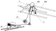
Fig. 2 is a schematic structural diagram of a ground wire hanging and detaching device according to an embodiment of the present invention;
fig. 3 is a schematic structural diagram of a ground wire hanging and detaching device according to an embodiment of the present invention;
fig. 4 is a cross-sectional view of a ground wire attaching and detaching device according to an embodiment of the present invention;
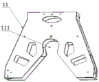
fig. 5 is a schematic structural diagram of a hooking body according to an embodiment of the present invention;
FIG. 6 is a schematic structural diagram of a sliding member according to an embodiment of the present invention;
fig. 7 is a schematic structural view of a clamping pliers according to an embodiment of the present invention;
fig. 8 is a schematic structural diagram of a ground wire unlocking member and a ground wire hook locking structure according to an embodiment of the present invention;
fig. 9 is a flow chart of a method for attaching and detaching a ground wire according to an embodiment of the present invention;
fig. 10 is a flow chart of a method for attaching and detaching a ground wire according to an embodiment of the present invention.
Detailed Description
Exemplary embodiments of the present disclosure will be described in more detail below with reference to the accompanying drawings. While exemplary embodiments of the present disclosure are shown in the drawings, it should be understood that the present disclosure may be embodied in various forms and should not be limited to the embodiments set forth herein. Rather, these embodiments are provided so that this disclosure will be thorough and complete, and will fully convey the scope of the disclosure to those skilled in the art. It should be noted that, without conflict, the embodiments of the present invention and features of the embodiments may be combined with each other. The invention will be described in detail below with reference to the drawings in connection with embodiments.
System embodiment:
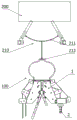
referring to fig. 1, a preferred structure of the ground wire attaching and detaching system provided by the embodiment of the invention is shown. As shown, the attaching and detaching system includes: the ground wire hanging and detaching device 100 and the unmanned aerial vehicle 200; the ground wire hanging and detaching device 100 is detachably hung on the unmanned aerial vehicle 200, and is used for flying along with the unmanned aerial vehicle 200 so as to be hung and detached on the wire 300, and then the ground wire (not shown in the figure) is hung on the wire 300, so that the grounding of the wire 300 is realized.
In specific implementation, the unmanned aerial vehicle 200 carries the ground wire hanging and detaching device 100 to fly, and can fly from the ground to the wire 300, so that the ground wire hanging and detaching device 100 can be hung and detached to the wire 300, and the ground wire can be lifted and locked to the ground wire hanging and detaching device 100, so as to realize the grounding of the wire 300. In this embodiment, an image collector (not shown in the figure) is further disposed on the unmanned aerial vehicle 200, and is configured to obtain a relative position between the ground wire hanging and detaching device 100 and the wire 300, so as to control the flight of the unmanned aerial vehicle 200 based on the relative position therebetween, so that the ground wire hanging and detaching device 100 is accurately clamped to the wire 300.
In this embodiment, as shown in fig. 1, a connector 210 is provided on the unmanned aerial vehicle 200, for hooking the ground wire hooking and unhooking device 100, so as to carry the ground wire hooking and unhooking device 100 for flying. Specifically, the connector 210 can be directly hooked on the ground wire hanging and dismounting device 100, so that the clamping and dismounting of the ground wire hanging and dismounting device 100 are facilitated, namely, the ground wire hanging and dismounting device 100 and the unmanned aerial vehicle 200 are locked and separated, and further connection and separation of the ground wire hanging and dismounting device 100 in the high altitude are facilitated, and the high altitude operation of construction operators is avoided. The connecting piece 210 is used for connecting and fixing the unmanned aerial vehicle 200 and the ground wire hanging and disassembling device 100, one end of the connecting piece 210 is connected with two foot frames of the unmanned aerial vehicle 200, and the other end of the connecting piece 210 is connected with the hanging and taking piece 12 of the ground wire hanging and disassembling device 100, so that the unmanned aerial vehicle and the ground wire hanging and disassembling device 100 can be disassembled and hung quickly.
With continued reference to fig. 1, the connector 210 includes: a connector body 211 and a multi-jaw hook 212; wherein, two ends (left and right ends as shown in fig. 1) of the connector body 211 are respectively connected with two foot stands of the unmanned plane 200; the fixed end (top end as shown in fig. 1) of the multi-claw hook 212 is disposed on the connector body 211, and the hook end (bottom end as shown in fig. 1) is of a multi-claw structure for hooking the ground wire hooking and unhooking device 100.
In particular, the connector multi-jaw hook 212 is configured in a "multi-jaw" configuration, such as: the three-jaw type, four-jaw type, five-jaw type and other multi-jaw design structures realize reliable connection, difficult slippage, buffer the stress of the unmanned aerial vehicle, ensure that the unmanned aerial vehicle is not limited in flight and strong in flexibility, and solve the problems of complex field operation, inconvenience in quick disassembly and hanging, inflexible operation and the like of connection modes such as hard bracket connection, rope connection and the like.
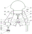
With continued reference to fig. 1-4, the ground wire hanging and removing device 100 includes: the wire clamping assembly 1 and the ground wire dismantling and fixing assembly 2; the wire clamping assembly 1 is used for being hung on the unmanned aerial vehicle 200 to be hung on the wire 300 along with the unmanned aerial vehicle 200, and the wire clamping assembly 1 is clamped on the wire 300 in a detachable mode when the unmanned aerial vehicle 200 releases the wire clamping assembly 1; the ground wire disassembling and fixing assembly 2 is arranged on the wire clamping assembly 1 and is used for being hung on the wire 300 along with the wire clamping assembly 1 and capable of lifting and pulling a ground wire to the wire clamping assembly 1 so as to realize the grounding of the wire 300.
In specific implementation, the wire clamping assembly 1 and the ground wire disassembling and fixing assembly 2 are connected, as shown in fig. 2, the wire clamping assembly 1 can be hooked on the connecting piece 210 of the unmanned aerial vehicle 200, so that the connection and disconnection of the ground wire hanging and disassembling device 100 and the wire 300, especially the high-altitude wire, can be realized by controlling the unmanned aerial vehicle 200 to mount and hang the ground wire hanging and disassembling device 100 to move and lift off. The ground wire dismounting and fixing assembly 2 is arranged on the wire clamping assembly 1 in a mode of being capable of moving relative to the wire clamping assembly 1, and is used for being hung on the wire 300 along with the wire clamping assembly 1 and capable of moving relative to the wire clamping assembly 2 so as to be capable of moving to the ground to hang the ground wire, and the ground wire is driven to move, namely to be lifted and locked on the wire clamping assembly 1, so that the ground of the wire 300 is realized. That is, the ground wire can be connected on the ground, and the ground wire can be disassembled, so that overhead operation is avoided.
With continued reference to fig. 2 and 4, the wire clamping assembly 1 includes: a hooking body 11, a hooking member 12, a sliding member 13, and a clamping jaw 14; the sliding member 13 is slidably disposed on the hooking body 11 relative to the hooking body 11, the hooking member 12 is disposed above the sliding member 13 and connected to the sliding member 13, the clamping pliers 14 are disposed on the hooking body 11, and the clamping pliers 14 are also connected to the sliding member 13. When the hanging piece 12 is hung on the unmanned aerial vehicle 200, an upward acting force is applied to the sliding piece 13 under the lifting action of the unmanned aerial vehicle 200, so that the sliding piece 13 slides upwards relative to the hanging main body 11, and an opening force is applied to the clamping pincers 14, so that the clamping pincers 14 are opened, and a wire enters the clamping groove 111 of the hanging main body 11 from the opening position; after the unmanned aerial vehicle 200 releases the hooking member 12, the sliding member 13 moves downward to reset under the action of gravity, and releases the clamping pincers 14, so that the clamping pincers 14 are closed, and the wire 300 is sealed and clamped at the clamping groove 111.
In specific implementation, the hanging main body 11 is used as a supporting body, and is used for slidably supporting the sliding piece 13, and can also rotatably support the clamping pincers 14, and of course, the hanging main body 11 can also be used for supporting the relevant parts of the ground wire disassembling and fixing assembly 2, such as a ground wire unlocking rope and a traction rope, through pulleys. The sliding member 13 is slidably disposed on the hooking body 11 along a vertical direction (relative to the position shown in fig. 2), and the hooking body 11 may be further provided with a limiting member for limiting the up-and-down movement limit position of the sliding member 13. The hanging member 12 is disposed above the hanging body 11 and the sliding member 13, and two ends of the hanging member 12 are respectively connected with the left and right ends of the sliding member 13, so as to ensure the stability of the sliding member 13 moving up and down. The hanging member 12 may have a plurality of shapes, such as an irregular wedge structure, a hanging ring, a hook, and a pull rod, so that the unmanned aerial vehicle is firmly hung and easily separated. The clamping jaw 14 is mounted on the hitching main body 11 with a motion structure design like an "X" type, a "scissors" type, a "claw jaw" type, etc., and as shown in fig. 4, the clamping jaw 14 and the sliding member 13 may be connected by a clamping unlocking rope 15 for applying an opening force to the clamping jaw 14 when the sliding member 13 moves upward relative to the hitching main body 11, so that the clamping jaw 14 is opened. As shown in fig. 4, both ends (upper and lower ends as shown in fig. 4) of the clamping unlocking rope 15 are hooked on the bottom end of the slider 13 and the left or right side of the clamping jaw 14, respectively, so that when the slider 13 slides upward, the clamping jaw 14 applies a leftward or rightward opening force, and thus the clamping jaw 14 opens; of course, when the unmanned aerial vehicle 200 releases the hanging member 12, the hanging member 12 and the sliding member 13 slide downward under the action of gravity, and then release the opening force to the clamping pincers 14, so that the clamping pincers 14 are automatically closed. The hitching main body 11 is provided with a clamping supporting pulley 112, so that the clamping unlocking rope 15 can bypass the clamping supporting pulley 112, and the steering of the clamping unlocking rope 15 is supported, so that the acting force direction exerted by the clamping unlocking rope 15 is adjusted, and the upward acting force exerted by the sliding piece 13 is converted into an opening force exerted by the clamping unlocking rope 15 to the upper left or the upper right on the clamping pliers 14. In this embodiment, two clamping supporting pulleys 112 are correspondingly disposed on each clamping unlocking rope 15, however, the number of the clamping supporting pulleys may be other values, and the number of the clamping supporting pulleys is not limited in this embodiment.
In this embodiment, to ensure the stability of the clamping jaw 14, it is preferable that, as shown in fig. 4, a return spring 16 is provided on the clamping jaw 14 for applying a return force to the clamping jaw 14 when the clamping jaw 14 is in the released state, so as to return the clamping jaw 14 to the closed state. Specifically, after the unmanned aerial vehicle 200 releases the hanging member 12, the sliding member 13 moves downward under the action of gravity to reset, and releases the clamping pincers 14, so that the clamping pincers 14 rotate to a closed state under the action of the reset force, and further the wire 300 is sealed and locked and clamped at the clamping groove 111, so that the stability of clamping can be ensured. One end of the return spring 16 is fixed to the hooking body 11, and the other end is fixed to the clamping jaw 14, so that when the clamping jaw 14 is opened, the return spring 16 compresses and applies a return force to the clamping jaw 14, so that the clamping jaw 14 can be returned to a closed state after being released.
Fig. 5 is a schematic structural diagram of a hooking body according to an embodiment of the present invention. As shown, the inside of the hooking body 11 is hollow so that the slider 13 and the clamping jaw 14 can be at least partially disposed inside the hooking body 11; the top of the hanging body 11 is also provided with an opening. The whole design of the hanging main body 11 can adopt a plurality of structures such as inverted Y-shaped structures, inverted U-shaped structures and horn mouth structures, so that the lead 300 can enter the clamping groove 111 more easily, wherein the clamping groove 111 is of a semi-arc structure at the clamping position, the lead 300 can be better attached, the lead 300 is prevented from slipping, and the lead 300 is not damaged. As shown in fig. 5, the hooking body 11 may be provided with a lightening hole to facilitate the lifting of the device. As shown in fig. 2, the hanging main body 11 is provided with a ground wire unlocking rope runner bracket 113 and a traction rope pulley bracket 114, which are used for supporting pulleys, so that the ground wire unlocking rope and the traction rope of the ground wire disassembling and fixing assembly 2 can bypass the hanging main body 11, and further, two ends of the ground wire unlocking rope and the traction rope are respectively arranged at two sides (left and right sides as shown in fig. 2) of the hanging main body 11, and further, when the wire clamping assembly 1 is clamped on the wire 300, two ends of the ground wire unlocking rope and the traction rope are respectively arranged at two sides (left and right sides as shown in fig. 3) of the wire 300, thereby ensuring the stability of the device, avoiding the toppling of the device, and ensuring the stability of the device clamped on the wire 300. Of course, the hitching body 11 may also be provided with a pulley bracket 115, the pulley bracket 115 being adapted to support two pulleys for respectively winding a ground wire unlocking rope and a pulling rope.
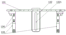
Referring to fig. 6, a schematic structural diagram of a sliding member according to an embodiment of the present invention is shown. As shown, the slider 13 includes: a hitch body cover 131, a guide bracket 132, and at least one sliding bracket 133; wherein, the guiding bracket 132 and the at least one sliding bracket 133 are both disposed on the hanging body cover 131, and the hanging body cover 131 is used for closing the top opening of the hanging body 11 to seal the inside of the hanging body 11. The sliding bracket 133 is slidably coupled to the inside of the hooking body 11, and the guide bracket 132 is used to guide the sliding of the sliding bracket 133.
In particular, two ends of the hooking member 12 are respectively connected to two ends of the upper surface of the hooking body cover 131, so as to pull the hooking body cover 131 to move upward relative to the hooking body 11. The sliding brackets 133 may be two and are disposed below the hanging body cover 131, and are respectively and fixedly connected to two ends (left and right ends as shown in fig. 6) of the hanging body cover 131, so as to slide relative to the hanging body 11 under the driving of the hanging body cover 131. In the present embodiment, the sliding bracket 133 is provided with a rolling member 134 for reducing friction force between the sliding bracket 133 and the hooking body 11 by rolling. The guide bracket 132 is disposed at a middle position below the hooking body cover 131, for guiding the up-and-down movement of the sliding bracket 133; the guide bracket 132 may have a U-shaped structure, and two side walls thereof are clamped at the front and rear sides of the hanging body cover 131 so as to be clamped at the front and rear sides of the hanging body 11. In this embodiment, as shown in fig. 2, the hanging main body 11 is provided with a guide shaft 116, the guide bracket 132 is provided with a guide groove 1321 along the groove depth direction (the vertical direction shown in fig. 2), and the guide shaft 116 is slidably inserted into the guide groove 1321 to guide the sliding of the sliding bracket 133, so that the sliding piece 13 and the hanging main body 11 are tightly slidably connected. The rolling element 134 may be a bearing structure or other structures.
Referring to fig. 7, a schematic structural diagram of a clamping jaw according to an embodiment of the present invention is shown. As shown, the clamping jaw 14 includes: two clamping jaw bodies 141; wherein, two clamping pincers bodies 141 set up relatively to, two clamping pincers bodies 141 are articulated mutually for relative rotation can open and make wire 300 can get into between two clamping pincers bodies 141, can also close and seal the lock and clamp wire 300 between two clamping pincers bodies 141.
In particular, the middle positions of the two clamping jaw bodies 141 are hinged to each other and the hinge shaft is fixed to the hooking body 11, so that the two clamping jaw bodies 141 can both rotate around the axis of the hinge shaft, thereby realizing opening and closing, i.e., tightening, between the two clamping jaw bodies 141, and the wire 300 can be clamped between the two clamping jaw bodies 141 when the two clamping jaw bodies 141 are closed. In this embodiment, each clamping jaw body 141 may further be provided with a fastening stop lever 142, one end (the lower end as shown in fig. 7) of the fastening stop lever 142 is rotatably connected to the clamping jaw body 141, and the other end is slidably connected to the clamping jaw body 141 and is used for abutting against the fastening stop lever 142 on the other clamping jaw body 141, so that the two fastening stop levers 142 abut against each other to seal a gap between the two clamping jaw bodies 141, further preventing the wire 300 from falling from the two clamping jaw bodies 141, preventing the device from falling, and realizing the anti-falling function. In this embodiment, the latch lever 142 is further connected to the slider 13, and is used to drive the clamp body 141 to rotate under the action of the slider 13, so that the clamp body 141 is opened, that is, the top end of the latch release rope 15 is connected to the bottom end of the slider 13, and the bottom end of the latch release rope 15 is connected to the latch lever 142, so that when the slider 13 slides upwards, the latch lever 142 is pulled to swing relative to the clamp body 141, the left latch lever 142 shown in fig. 7 rotates counterclockwise until the limit position of relative movement, and the slider 13 continues to pull the latch lever 142, so that the latch lever 142 drives the clamp body 141 to rotate synchronously with the clockwise rotation of the left clamp body 141, as shown in fig. 7, to the opened state. In this embodiment, two return springs 16 are respectively connected to the two clamping jaw bodies 141, and when the clamping jaw bodies 141 are opened, the return springs 16 are compressed, so that the clamping jaw bodies 141 can reversely rotate to a closed state under the action of the return force of the return springs 16 after being released. The two clamping jaw bodies 141 are symmetrically arranged in a left-right direction, and the angles of the two clamping jaw bodies are consistent when the two clamping jaw bodies are opened or closed.
With continued reference to fig. 7, a return spring 143 is further disposed between the catch lever 142 and the clamp body 141, for applying a return force to the catch lever 142, so that the catch lever 142 returns to abut against the other catch lever 142. Specifically, after the clamping jaw body 141 expands along with the clamping jaw rod 142, after the clamping jaw rod 142 is released, the clamping jaw body 141 can drive the clamping jaw rod 142 to reset under the action of the reset spring 16, and at the same time, the clamping jaw rod 142 continues to reversely swing under the action of the reset force of the reset elastic piece 143 until the two clamping jaw rods 142 are tightly abutted against each other. The snap stop lever 142 and the return spring 16 are respectively connected with two ends of the clamping clamp body 141, and two ends of the clamping clamp body 141 are arranged at two sides of a hinge point of the clamping clamp body 141.
With continued reference to fig. 7, the end portions (top ends as shown in fig. 7) of the two clamping jaw bodies 141 are provided with supporting pulleys 144 for guiding the traction rope of the ground wire disassembling and fixing assembly 2 so that the traction rope can be wound around each supporting pulley, so that the two clamping jaw bodies 141 can clamp the wire 300, and the traction rope can be supported, so that the structure is simple and compact. As shown in fig. 4, a balance wheel 145 is disposed between the two support pulleys 144, so that the traction rope sequentially bypasses one of the support pulleys 144, the balance wheel 145 and the other support pulley 144, and the traction rope and the balance wheel 145 can make the upper sides of the clamping pliers body 141 in a force balance manner.
With continued reference to fig. 7, the clamping jaw body 141 includes: a clamping section 1411, a reset section 1412, and a load-bearing section 1413; the clamping section 1411 is connected with the resetting section 1412, and the clamping section 1411 is in an arc structure and is used for enclosing the two clamping sections 1411 of the two clamping clamp bodies 141 to form a sealing hole when the two clamping clamp bodies 141 are in a closed state so as to clamp the lead 300 at the sealing hole through the clamping section 1411; the side of the clamping section 1411 facing away from the restoring section 1412 (the lower side as shown in fig. 7) is further provided with a bearing section 1413 for bearing a load, and is further used for connecting the sliding member 13 so as to rotate under the action of the sliding member 13, thereby driving the clamping section 1411 and the restoring section 1412 to synchronously rotate therewith. Specifically, the clamping section 1411, the reset section 1412 and the bearing section 1413 are in an integral structure, and rotate synchronously. The reset segment 1412 and the bearing segment 1413 are straight segments and are respectively arranged on the upper side and the lower side of the clamping segment 1411; the connection positions of the clamping section 1411 and the restoring section 1412 serve as hinge points and are hinged on the hooking main body 11, the supporting pulley 144 is arranged at the top end of the restoring section 1412, the restoring spring 16 is connected with the restoring section 1412, and the buckle baffle rod 142 is arranged on the bearing section 1413 so as to be connected with the sliding piece 13 through the buckle baffle rod 142, so that the sliding piece 13 integrally rotates to an open state under the action of the sliding piece 13. Wherein, the clamping section 1411 is arc structure to be equipped with the centre gripping arch on the inner wall, the top is slick and sly, better laminating contact wire 300, wire 300 difficult wearing and tearing just increase the steadiness of centre gripping wire 300.
With continued reference to fig. 2, the ground wire disconnecting and fixing assembly 2 includes: a ground wire unlocking piece 21 and a ground wire clamping hook 22; wherein, the ground wire unlocking piece 21 is connected with the ground wire clamping hook 22, and is used for locking the ground wire clamping hook 22 at the locking position of the ground wire unlocking piece 21; the ground wire unlocking piece 21 is connected with an unlocking driving piece 23 for applying a force to the ground wire unlocking piece 21 to unlock the locking of the ground wire clamping hook 22; the ground wire hook 22 is connected with a traction piece 24 for applying traction force to the ground wire hook 22, so that after the ground wire unlocking piece 21 unlocks the locking of the ground wire hook 22, the ground wire hook 22 moves up and down under the traction force of the traction piece 24, and then the ground wire hook 22 moves down to the ground surface and then is connected with the ground wire, and the ground wire moves up to the locking position along with the ground wire hook 22, and is locked at the locking position through the ground wire unlocking piece 21, so that the ground wire is hooked.
In particular, the ground wire unlocking member 21 may be disposed on the hanging wire main body 11, for locking and unlocking the ground wire hook 22, and the lockable ground wire hook 22 can be connected to the ground wire unlocking member 21 to enable the ground wire unlocking member 21 and the ground wire hook 22 to fly under the action of the unmanned aerial vehicle 200 and be fixed to the wire 300 along with the hanging wire main body 11. The unlocking of the ground wire hook 22 is achieved by controlling the ground wire unlocking member 21 through the unlocking driving member 23, the ground wire hook 22 is released through the traction member 24, the ground wire hook 22 can move downwards from the height of the wire 300 to the ground so as to enable the ground wire to be connected to the ground wire hook 22, the end portion of the ground wire connected to the ground wire hook 22 moves upwards to the ground wire unlocking member 21 along with the ground wire hook 22 through the traction of the traction member 24, the ground wire unlocking member 21 is controlled through the unlocking driving member 23, locking of the ground wire hook 22 is achieved, the ground wire hook 22 is fixed to the ground wire unlocking member 21, namely, the ground wire is connected to a wire, and grounding of the wire is achieved. In the present embodiment, the ground wire hook 22 is provided with a connection hole 221 for connecting the weight member 25, so that the ground wire hook 22 can move downward to the ground under the gravity action of the weight member 25 in the unlocked state to connect the ground wire; the weight 25 is used for balancing the gravity center of the whole device and is used for pulling the traction piece 24, so that the traction piece 24 falls more smoothly; the weight 25 may be composed of multiple sets of weight plates, and the number of weight plates is determined according to the height of the target device to be hooked in the high altitude (such as a high altitude wire) and the traction requirement of the traction member 24, in combination with the load of the unmanned aerial vehicle 200. The traction piece 24 is a traction rope, and can be an insulating rope, and is used for lifting and lowering the ground wire, one end of the traction piece is connected with the ground wire clamping hook 22, and the other end of the traction piece can be connected with the winch 26, so that the winding and unwinding of the traction rope can be controlled through the winch 26, and further the lifting and the lowering of the ground wire clamping hook 22 can be controlled; the unlocking driving piece 23 is a ground wire unlocking rope, which can be a steel wire rope, and is used for applying an acting force to the ground wire unlocking piece 21 to cooperatively complete locking and unlocking of the ground wire clamping hook 22, one end of the ground wire unlocking rope is connected with the ground wire unlocking piece 21, the other end of the ground wire unlocking rope can be provided with a winder 27, and the ground wire unlocking driving piece is pulled or loosened by a ground auxiliary operator, and the ground wire unlocking piece 21 is pulled through the ground wire unlocking rope to unlock the ground wire clamping hook 22; the ground wire unlocking piece 21 can be automatically reset to the locking position by releasing the ground wire unlocking rope.
With continued reference to fig. 2 and 3, the ground wire unlocking member 21 is disposed on a first side (left side as shown in fig. 2) of the wire clamping assembly 1, and one end (left lower end as shown in fig. 2) of the traction rope is connected to the ground wire hook 22 and extends upward to the wire clamping assembly 1, and bypasses the wire clamping assembly 1 to a second side (right side as shown in fig. 2) of the wire clamping assembly 1, so that the traction rope is disposed at the other end (right lower end as shown in fig. 2) of the second side of the wire clamping assembly 1 as a traction end, and the traction end and the ground wire hook 22 are disposed on both sides of the wire clamping assembly 1, i.e., on both sides of the wire 300, respectively; one end (left lower end as shown in fig. 2) of the ground wire unlocking rope is connected with the ground wire unlocking piece 21 and extends upwards to the top of the wire clamping assembly 1, and bypasses from the top of the wire clamping assembly 1 to the second side of the wire clamping assembly 1, so that the other end (right lower end as shown in fig. 2) of the ground wire unlocking rope, which is positioned on the second side of the wire clamping assembly 1, serves as an unlocking driving end, and the unlocking driving end and the ground wire clamping hook 22 are respectively arranged on two sides of the wire clamping assembly 1, namely on two sides of the wire 300, so that traction lifting can be facilitated, stability of the device can be ensured, and inclined overturning and falling of the device can be avoided.
Referring to fig. 8, a schematic structural diagram of a ground wire unlocking member and a ground wire hook locking structure according to an embodiment of the present invention is shown. As shown, the ground wire unlocking member 21 includes: a ground clip box 211, a right clip block 212 and a left clip block 213; at least one of the right clamping block 212 and the left clamping block 213 is movably arranged in the ground wire clamping box 211, and at least one of the right clamping block 212 and the left clamping block 213 is connected with the unlocking driving piece 23 and used for moving the right clamping block 212 and the left clamping block 213 back to back under the action of the unlocking driving piece 23 so as to unlock the ground wire clamping hook 22. Specifically, in this embodiment, the left clamping block 213 is slidably disposed in the ground wire clamping box 211 along the horizontal direction, and the ground wire unlocking rope passes from the left side wall of the ground wire clamping box 211 into the ground wire clamping box 211 and is connected to the left clamping block 213, so as to apply an unlocking force moving leftwards to the left clamping block 213, so that the left clamping block 213 moves leftwards, and the separation from the right clamping block 212 is realized, and further the unlocking of the ground wire hook 22 is realized. In order to ensure the smoothness of unlocking the ground wire hook 22, preferably, the right clamping block 212 is also slidably arranged in the ground wire clamping box 211 along the horizontal direction, and the right clamping block 212 and the left clamping block 213 are both provided with a locking return spring 214 so as to be capable of resetting to a locking position, so that the ground wire hook 22 can be locked when the ground wire hook 22 moves to the locking position, and the locking is more stable. The opposite wall surfaces of the right clamping block 212 and the left clamping block 213 are provided with a yielding groove which is matched with the ground wire clamping hook 22, and is used for forming a clamping groove between the right clamping block 212 and the left clamping block 213 and locking the ground wire clamping hook 22, so that the conical ground wire clamping hook 22 is convenient to lock and unlock. In order to facilitate the ground wire hook 22 to smoothly enter the ground wire unlocking member 21, a flare structure 2111 is preferably provided at the bottom of the ground wire clamping box 211 for guiding the ground wire hook 22 to enter and exit the ground wire clamping box 211.
In the present embodiment, the ground line card box 211 includes: cartridge body 2112 and ground wire cartridge end cap 2113 disposed at the top opening of cartridge body 2112.
In summary, the grounding wire hanging and disassembling device and system provided by the embodiment are hung on the unmanned aerial vehicle 200 through the wire clamping assembly 1 so as to be hung on the wire 300 along with the unmanned aerial vehicle 200, and the wire clamping assembly 1 is clamped on the wire 300 in a detachable manner while the unmanned aerial vehicle 200 releases the wire clamping assembly 1; hang on wire 300 along with wire clamping assembly 1 through ground wire tear solid subassembly 2 to can carry and draw the earth connection to wire clamping assembly 1 on, with the ground connection that realizes wire 300, the operation is whole does not need personnel to step on the tower, has greatly promoted flexibility, reliability and the security that the earth connection was hung and torn open, has reduced high altitude fall and response electric shock risk, and operation intellectuality and degree of automation are high, have solved current earth connection and have hung and have torn open the problem that the high limit, high altitude construction operation is comparatively inconvenient.
Method embodiment:
referring to fig. 9, a flow chart of a method for attaching and detaching a grounding wire according to an embodiment of the present invention is shown. As shown in the figure, the hanging and dismantling method adopts the hanging and dismantling system or the hanging and dismantling device to hang and dismantle the ground wire, and the hanging and dismantling method comprises the following steps:
And (S1) mounting, namely hanging the wire clamping assembly on the unmanned aerial vehicle.
Specifically, firstly, the unmanned aerial vehicle 200 is taken out, and the unmanned aerial vehicle 200 and the connecting piece 210 are installed and fixedly connected; then, the weight 25, that is, the weight piece is attached to the ground hook 22 of the ground wire attaching/detaching device 100, and the ground wire attaching/detaching device 100 is attached to the connector 210.
And step S2, taking off and climbing through the unmanned aerial vehicle flying carrying wire clamping assembly and the ground wire dismounting assembly until the unmanned aerial vehicle flies to a position exceeding the height of the wire hanging position to hover.
Specifically, first, the unmanned aerial vehicle 200 is controlled so that the unmanned aerial vehicle 200 carries the ground wire hanging and detaching device 100 to take off and climb vertically, and the ground wire unlocking rope and the traction rope are released by the reel 27 and the winch 26 synchronously, so that the weight piece 25, the ground wire unlocking rope and the traction rope of the ground wire hanging and detaching device 100 are kept on different sides (the left side and the right side as shown in fig. 3) inside and outside of target equipment to be hung (such as a wire 300, particularly a high-altitude wire); and hovering the unmanned aerial vehicle 200 to a position slightly exceeding the height of the hanging position of the wire 300.
And a wire clamping step S3, namely carrying the wire clamping assembly and the ground wire dismounting and fixing assembly to fly horizontally through the unmanned aerial vehicle until the wire clamping assembly and the ground wire dismounting and fixing assembly descend through the unmanned aerial vehicle until the wire clamping assembly is hung on the wire, and releasing the wire clamping assembly through the unmanned aerial vehicle, so that the wire clamping assembly is clamped on the wire.
Specifically, first, the unmanned aerial vehicle 200 is controlled to fly horizontally above the wire 300, the unmanned aerial vehicle 200 is carried with an image collector such as a camera aiming at the ground wire hanging and disassembling device 100, especially the wire clamping assembly 1, to shoot and slowly descend, the real-time image returned by the camera is used for checking the hanging and disassembling position until the ground wire hanging and disassembling device 100, namely the wire clamping assembly 1, is hung on the wire 300, and the flying of the unmanned aerial vehicle 200 is controlled to release the wire clamping assembly 1, so that the wire clamping assembly 1 is clamped on the wire 300.
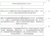
And S4, the ground wire hooking step is carried out, the ground wire disassembling and fixing assembly is released, so that the ground wire disassembling and fixing assembly moves downwards to the ground surface relative to the wire clamping and fixing assembly, one end wire clamp of the ground wire is fixed, the other end of the ground wire is fixed and locked with the ground wire disassembling and fixing assembly, the ground wire disassembling and fixing assembly carries the ground wire to move upwards to the wire clamping and fixing assembly and is locked on the wire clamping and fixing assembly, and the ground connection of the wire is realized.
Specifically, firstly, the ground wire disassembling and fixing assembly 2 is released, so that the ground wire disassembling and fixing assembly moves downwards to the ground relative to the ground wire clamping assembly, a ground wire unlocking rope can be lifted, the ground wire unlocking piece 21 is released to lock the ground wire clamping hook 22, and the ground wire clamping hook 22 is released under the traction of the weight piece 25, so that the ground wire clamping hook 22 moves downwards to the ground; then, one end wire clamp of the grounding wire is fixed, and can be fixed on a tower leg of a tower, or a ground temporary grounding body, or a cross arm which is electrically and directly connected with a tower grounding device and is locked, and the other end of the grounding wire clamp is fixed and locked with the ground wire dismounting and fixing assembly 2, for example, the grounding wire clamp can be fixed and locked by screws; finally, the ground wire dismounting and fixing assembly carries the ground wire to move upwards to the wire clamping assembly and is locked on the wire clamping assembly, so that the ground wire is grounded, ground operators can pull the ground wire clamping hook 22 to be lifted upwards between the right clamping block 213 and the left clamping block 212 by pulling the pulling rope, the ground wire unlocking rope is released, the right clamping block 213 and the left clamping block 212 relatively move to clamp and lock the ground wire clamping hook 22, and the ground wire is hung on the wire 300.
Referring to fig. 10, a flowchart of a ground wire attaching/detaching method according to an embodiment of the present invention is shown. As shown, the disassembly method comprises the following steps:
and (S1) mounting, namely hanging the wire clamping assembly on the unmanned aerial vehicle.
And step S2, taking off and climbing through the unmanned aerial vehicle flying carrying wire clamping assembly and the ground wire dismounting assembly until the unmanned aerial vehicle flies to a position exceeding the height of the wire hanging position to hover.
And a wire clamping step S3, namely carrying the wire clamping assembly and the ground wire dismounting and fixing assembly to fly horizontally through the unmanned aerial vehicle until the wire clamping assembly and the ground wire dismounting and fixing assembly descend through the unmanned aerial vehicle until the wire clamping assembly is hung on the wire, and releasing the wire clamping assembly through the unmanned aerial vehicle, so that the wire clamping assembly is clamped on the wire.
And S4, the ground wire hooking step is carried out, the ground wire disassembling and fixing assembly is released, so that the ground wire disassembling and fixing assembly moves downwards to the ground surface relative to the wire clamping and fixing assembly, one end wire clamp of the ground wire is fixed, the other end of the ground wire is fixed and locked with the ground wire disassembling and fixing assembly, the ground wire disassembling and fixing assembly carries the ground wire to move upwards to the wire clamping and fixing assembly and is locked on the wire clamping and fixing assembly, and the ground connection of the wire is realized.
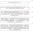
And S5, releasing the ground wire dismounting and fixing assembly, so that the ground wire dismounting and fixing assembly carries the ground wire to move downwards to the ground relative to the wire clamping assembly, the locking of the ground wire and the ground wire dismounting and fixing assembly is dismounted, the ground wire dismounting and fixing assembly is driven to move upwards to the wire clamping assembly and lock relative to the wire clamping assembly, the wire clamping assembly is hung and taken by an unmanned aerial vehicle, and the ground wire dismounting and fixing assembly takes off and lands, so that the ground wire is dismounted.
Specifically, the ground operator releases the lock of the ground wire unlocking piece 21 to the ground wire hook 22 by pulling the ground wire unlocking rope, and releases the ground wire hook 22 under the traction of the weight piece 25, so that the ground wire hook 22 moves down to the ground; then, the connection between the grounding wire and the ground wire clamping hook 22 is disassembled, and one end wire clamp of the grounding end of the grounding wire can be disassembled; the ground operator pulls the traction rope to enable the traction rope to pull the ground wire clamping hook 22 to be pulled upwards between the right clamping block 213 and the left clamping block 212, the ground wire unlocking rope is released, the right clamping block 213 and the left clamping block 212 relatively move to clamp and lock the ground wire clamping hook 22, the ground wire is restored to an initial state, and the ground wire unlocking rope and the traction rope are released; finally, the unmanned aerial vehicle 200 is controlled to fly to the position where the ground wire hanging and detaching device 100 is located, and the ground wire hanging and detaching device 100 is detached and landed.
In summary, in the ground wire hanging and disassembling method provided by the embodiment, the wire clamping assembly 1 is hung on the unmanned aerial vehicle 200 to be hung on the wire 300 along with the unmanned aerial vehicle 200, and the wire clamping assembly 1 is clamped on the wire 300 in a detachable manner while the unmanned aerial vehicle 200 releases the wire clamping assembly 1; hang on wire 300 along with wire clamping assembly 1 through ground wire tear solid subassembly 2 to can carry and draw the earth connection to wire clamping assembly 1 on, with the ground connection that realizes wire 300, the operation is whole does not need personnel to step on the tower, has greatly promoted flexibility, reliability and the security that the earth connection was hung and torn open, has reduced high altitude fall and response electric shock risk, and operation intellectuality and degree of automation are high, have solved current earth connection and have hung and have torn open the problem that the high limit, high altitude construction operation is comparatively inconvenient.
It should be noted that, in the description of the present invention, terms such as "upper," "lower," "left," "right," "inner," "outer," and the like indicate directions or positional relationships based on the directions or positional relationships shown in the drawings, which are merely for convenience of description, and do not indicate or imply that the apparatus or elements must have a specific orientation, be constructed and operated in a specific orientation, and thus should not be construed as limiting the present invention.
Furthermore, it should be noted that, in the description of the present invention, unless explicitly specified and limited otherwise, the terms "mounted," "connected," and "connected" are to be construed broadly, and may be either fixedly connected, detachably connected, or integrally connected, for example; can be directly connected or indirectly connected through an intermediate medium, and can be communication between two elements. The specific meaning of the above terms in the present invention can be understood by those skilled in the art according to the specific circumstances.
It will be apparent to those skilled in the art that various modifications and variations can be made to the present invention without departing from the spirit or scope of the invention. Thus, it is intended that the present invention also include such modifications and alterations insofar as they come within the scope of the appended claims or the equivalents thereof.
Claims (17)
1. The utility model provides a ground wire hangs and tears device open which characterized in that includes: the wire clamping assembly and the ground wire dismantling and fixing assembly; wherein,,
the wire clamping assembly is used for being hung on the unmanned aerial vehicle so as to be hung on a wire along with the unmanned aerial vehicle, and the wire clamping assembly is clamped on the wire in a detachable mode when the unmanned aerial vehicle releases the wire clamping assembly;
The ground wire disassembling and fixing assembly is arranged on the wire clamping assembly and is used for being hung on the wire along with the wire clamping assembly, and the ground wire can be lifted and pulled to the wire clamping assembly so as to realize the grounding of the wire.
2. The ground wire attachment/detachment apparatus of claim 1 wherein the wire clamping assembly comprises: the clamping clamp comprises a hanging main body, a hanging piece, a sliding piece and clamping pincers; wherein,,
the sliding piece is arranged on the hanging main body in a manner of being capable of sliding relative to the hanging main body, the hanging piece is arranged above the sliding piece and is connected with the sliding piece, the clamping pliers are arranged on the hanging main body and are also connected with the sliding piece, and the clamping pliers are provided with reset springs for applying reset force to the clamping pliers when the clamping pliers are in a release state so as to enable the clamping pliers to be reset to a closed state;
when the hanging piece is hung on the unmanned aerial vehicle, an upward acting force is applied to the sliding piece under the lifting action of the unmanned aerial vehicle, so that the sliding piece slides upwards relative to the hanging main body, and an opening force is applied to the clamping pincers, so that the clamping pincers are opened, and a wire enters the clamping groove of the hanging main body from the opening position;
After the unmanned aerial vehicle releases the hanging piece, the sliding piece moves downwards under the action of gravity to reset, and releases the clamping pincers, so that the clamping pincers are closed, and then the wire sealing lock is clamped at the clamping groove.
3. The ground wire attaching and detaching device according to claim 2, wherein the clamping pincers include: two clamping pliers bodies; wherein,,
the two clamping pincers bodies are oppositely arranged, and the two clamping pincers bodies are hinged and used for relatively rotating, so that a wire can enter the two clamping pincers bodies and can be closed to clamp the wire between the two clamping pincers bodies.
4. The ground wire attachment/detachment device of claim 3, characterized in that,
the clamping forceps comprise clamping forceps bodies, clamping forceps bodies and clamping forceps, wherein the clamping forceps bodies are respectively provided with a clamping forceps body, one end of each clamping forceps body is rotatably connected to the clamping forceps body, the other end of each clamping forceps body is slidably connected to the clamping forceps body and is used for being abutted to the clamping forceps body, so that the clamping forceps body is abutted to the clamping forceps body, and a gap between the clamping forceps body is blocked;
the clamping and blocking rod is also connected with the sliding piece and used for driving the clamping and clamping clamp body to rotate under the action of the sliding piece so as to enable the clamping and clamping clamp body to open.
5. The ground wire attachment/detachment device of claim 4, characterized in that,
and a reset spring piece is further arranged between the buckle blocking rod and the clamping clamp body and used for applying a reset force to the buckle blocking rod so as to enable the buckle blocking rod to reset to be abutted against the other buckle blocking rod.
6. The ground wire attachment/detachment device of any one of claims 1 to 5, characterized in that the ground wire detachment assembly comprises: a ground wire unlocking piece and a ground wire clamping hook; wherein,,
the ground wire unlocking piece is connected with the ground wire clamping hook and is used for locking the ground wire clamping hook at the locking position of the ground wire unlocking piece;
the ground wire unlocking piece is connected with an unlocking driving piece and is used for applying acting force to the ground wire unlocking piece so as to unlock the locking of the ground wire clamping hook;
the ground wire hook is connected with a traction piece and is used for applying traction force to the ground wire hook, so that after the ground wire unlocking piece unlocks the ground wire hook, the ground wire hook moves up and down under the traction force of the traction piece, then the ground wire hook moves downwards to the ground and is connected with the ground wire, the ground wire moves upwards to a locking position along with the ground wire hook, and the ground wire unlocking piece locks at the locking position to realize the hanging connection of the ground wire.
7. The ground wire attaching and detaching device according to claim 6, wherein the ground wire unlocking member includes: the ground clamp box, the right clamp block and the left clamp block; wherein,,
at least one of the right clamping block and the left clamping block is movably arranged in the ground wire clamping box, and at least one of the right clamping block and the left clamping block is connected with the unlocking driving piece and used for moving back to back under the action of the unlocking driving piece so as to unlock the ground wire clamping hook.
8. The ground wire attachment/detachment device of claim 7, characterized in that,
the bottom of the ground wire clamping box is provided with a horn mouth structure which is used for guiding the ground wire clamping hook to enter and exit the ground wire clamping box.
9. The ground wire attachment/detachment device of claim 6, characterized in that,
the traction piece is a traction rope, and the unlocking driving piece is a ground wire unlocking rope;
the ground wire unlocking piece is arranged on the first side of the wire clamping assembly, one end of the traction rope is connected with the ground wire clamping hook and extends upwards to the wire clamping assembly, and the traction rope bypasses the wire clamping assembly to the second side of the wire clamping assembly, so that the other end of the traction rope, which is positioned on the second side of the wire clamping assembly, is used as a traction end, and the traction end and the ground wire clamping hook are respectively arranged on two sides of a wire;
One end of the ground wire unlocking rope is connected with the ground wire unlocking piece and extends upwards to the top of the wire clamping assembly, and the ground wire unlocking rope bypasses the top of the wire clamping assembly to the second side of the wire clamping assembly, so that the other end of the ground wire unlocking rope, which is positioned on the second side of the wire clamping assembly, serves as an unlocking driving end, and the unlocking driving end and the ground wire clamping hook are respectively arranged on two sides of a wire.
10. The ground wire attachment/detachment device of claim 6, characterized in that,
the ground wire clamping hook is provided with a connecting hole for connecting the weight piece, so that the ground wire clamping hook can downwards move to the ground under the gravity action of the weight piece in an unlocking state to be connected with the ground wire.
11. A ground wire attachment/detachment system characterized in that a ground wire attachment/detachment device according to any one of claims 1 to 10 is provided.
12. The ground wire attachment/detachment system of claim 11 further comprising:
the unmanned aerial vehicle is provided with a connecting piece for hooking the ground wire hooking and detaching device so as to carry the ground wire hooking and detaching device to fly;
the image collector is arranged on the unmanned aerial vehicle and used for acquiring the relative position between the ground wire hanging and detaching device and the wire so as to control the flight of the unmanned aerial vehicle based on the relative position between the ground wire hanging and detaching device and the wire.
13. The ground wire attachment/detachment system of claim 12 wherein the connector comprises:
the two ends of the connecting piece body are respectively connected with two foot frames of the unmanned aerial vehicle;
the multi-claw hook is characterized in that the fixed end of the multi-claw hook is arranged on the connecting piece body, and the hook end is of a multi-claw structure and is used for hanging the grounding wire hanging and dismantling device.
14. A method for attaching and detaching an earth wire, characterized in that an earth wire attaching and detaching device according to any one of claims 1 to 10 is employed, the attaching and detaching method comprising the steps of:
the method comprises the steps of mounting, namely hanging a wire clamping assembly on an unmanned aerial vehicle;
a climbing step, namely taking off and climbing by carrying the wire clamping assembly and the ground wire dismounting assembly through the flight of the unmanned aerial vehicle until the unmanned aerial vehicle flies to a position exceeding the height of the wire hanging position for hovering;
the method comprises the steps of conducting wire clamping, namely carrying a conducting wire clamping assembly and a ground wire dismantling and fixing assembly by an unmanned aerial vehicle to fly horizontally until the conducting wire clamping assembly and the ground wire dismantling and fixing assembly are carried by the unmanned aerial vehicle to the upper side of a conducting wire, descending until the conducting wire clamping assembly is hung on the conducting wire, and releasing the conducting wire clamping assembly by the unmanned aerial vehicle to clamp the conducting wire clamping assembly on the conducting wire;
And a ground wire hooking step, namely releasing the ground wire disassembling and fixing assembly so that the ground wire disassembling and fixing assembly moves downwards to the ground relative to the wire clamping and fixing assembly, fixing one end wire clamp of the ground wire, fixing and locking the other end of the ground wire with the ground wire disassembling and fixing assembly, moving the ground wire disassembling and fixing assembly with the ground wire upwards to the wire clamping and fixing assembly, and locking the ground wire clamping and fixing assembly to realize the grounding of the wire.
15. The method of claim 14, wherein the releasing the ground wire securing assembly moves the ground wire securing assembly downward to the ground surface relative to the wire clamping assembly, in particular:
and lifting the ground wire unlocking rope, releasing the locking of the ground wire unlocking piece on the ground wire clamping hook, and releasing the ground wire clamping hook under the traction of the weight piece, so that the ground wire clamping hook moves downwards to the ground.
16. The method for attaching and detaching the ground wire according to claim 14 or 15, wherein the ground wire detaching assembly moves the ground wire up to the wire clamping assembly and is locked on the wire clamping assembly, specifically:
and the traction rope is pulled, so that the traction rope pulls the ground wire clamping hook to be lifted upwards between the right clamping block and the left clamping block, and the ground wire unlocking rope is released, so that the right clamping block and the left clamping block relatively move to clamp and lock the ground wire clamping hook.
17. The ground wire hitching method as recited in claim 14 or 15, further comprising, after said ground wire hitching step, the steps of:
and in the disassembling step, the ground wire disassembling and fixing assembly is released, so that the ground wire disassembling and fixing assembly carries the ground wire to move downwards to the ground relative to the wire clamping and fixing assembly, the locking of the ground wire and the ground wire disassembling and fixing assembly is disassembled, the ground wire disassembling and fixing assembly is driven to move upwards to the wire clamping and fixing assembly and lock relative to the wire clamping and fixing assembly, the wire clamping and fixing assembly is hung and taken by an unmanned aerial vehicle, and the ground wire disassembling and fixing assembly takes off and lands and carries the wire clamping and fixing assembly and the ground wire disassembling and fixing assembly, so that the ground wire is disassembled.
Priority Applications (1)
| Application Number | Priority Date | Filing Date | Title |
|---|---|---|---|
| CN202211346985.4A CN116260069A (en) | 2022-10-31 | 2022-10-31 | Grounding wire hanging and detaching device, system and method |
Applications Claiming Priority (1)
| Application Number | Priority Date | Filing Date | Title |
|---|---|---|---|
| CN202211346985.4A CN116260069A (en) | 2022-10-31 | 2022-10-31 | Grounding wire hanging and detaching device, system and method |
Publications (1)
| Publication Number | Publication Date |
|---|---|
| CN116260069A true CN116260069A (en) | 2023-06-13 |
Family
ID=86686864
Family Applications (1)
| Application Number | Title | Priority Date | Filing Date |
|---|---|---|---|
| CN202211346985.4A Pending CN116260069A (en) | 2022-10-31 | 2022-10-31 | Grounding wire hanging and detaching device, system and method |
Country Status (1)
| Country | Link |
|---|---|
| CN (1) | CN116260069A (en) |
Cited By (4)
| Publication number | Priority date | Publication date | Assignee | Title |
|---|---|---|---|---|
| CN116487909A (en) * | 2023-06-21 | 2023-07-25 | 中国电力科学研究院有限公司 | Climbing-free grounding wire hanging and detaching device, system and method |
| CN117595139A (en) * | 2023-11-18 | 2024-02-23 | 国网安徽省电力有限公司蒙城县供电公司 | High-altitude hooking device for grounding wire of transformer substation |
| CN118399250A (en) * | 2024-04-15 | 2024-07-26 | 甘肃送变电工程有限公司 | Auxiliary hanging and dismantling grounding device for unmanned aerial vehicle hoisting |
| CN118712834B (en) * | 2024-08-28 | 2024-11-08 | 西安博展电力技术有限公司 | Unmanned aerial vehicle-based ground wire disassembling and assembling device with non-contact electricity testing function |
-
2022
- 2022-10-31 CN CN202211346985.4A patent/CN116260069A/en active Pending
Cited By (7)
| Publication number | Priority date | Publication date | Assignee | Title |
|---|---|---|---|---|
| CN116487909A (en) * | 2023-06-21 | 2023-07-25 | 中国电力科学研究院有限公司 | Climbing-free grounding wire hanging and detaching device, system and method |
| CN116487909B (en) * | 2023-06-21 | 2023-09-19 | 中国电力科学研究院有限公司 | Climbing-free grounding wire hanging and detaching device, system and method |
| CN117595139A (en) * | 2023-11-18 | 2024-02-23 | 国网安徽省电力有限公司蒙城县供电公司 | High-altitude hooking device for grounding wire of transformer substation |
| CN117595139B (en) * | 2023-11-18 | 2024-04-23 | 国网安徽省电力有限公司蒙城县供电公司 | High-altitude hooking device for grounding wire of transformer substation |
| CN118399250A (en) * | 2024-04-15 | 2024-07-26 | 甘肃送变电工程有限公司 | Auxiliary hanging and dismantling grounding device for unmanned aerial vehicle hoisting |
| CN118399250B (en) * | 2024-04-15 | 2024-09-27 | 甘肃送变电工程有限公司 | Auxiliary hanging and dismantling grounding device for unmanned aerial vehicle hoisting |
| CN118712834B (en) * | 2024-08-28 | 2024-11-08 | 西安博展电力技术有限公司 | Unmanned aerial vehicle-based ground wire disassembling and assembling device with non-contact electricity testing function |
Similar Documents
| Publication | Publication Date | Title |
|---|---|---|
| CN116260069A (en) | Grounding wire hanging and detaching device, system and method | |
| CN112587823B (en) | Anti-falling device based on unmanned aerial vehicle suspension and suspension method thereof | |
| CN109250115B (en) | Multi-rotor unmanned aerial vehicle power grid aerial work safety rope hanging method | |
| CN107344597B (en) | Unmanned ship deployment and recovery device, system and unmanned ship deployment and recovery method | |
| CN109390063B (en) | Automatic lifting appliance for reactor core guide column of pressurized water reactor nuclear power station | |
| CN210806586U (en) | Transmission line wire pulley | |
| CN112165022A (en) | Anti-drop hanging and dismounting transfer device for overhead operation of overhead transmission line | |
| CN116421906A (en) | Unmanned aerial vehicle prevents weighing down rope and lays frock | |
| CN214260407U (en) | Anti-falling device based on unmanned aerial vehicle hangs | |
| CN117855898A (en) | Method for hanging and detaching grounding wire | |
| US20220233891A1 (en) | Rope-Lowering Device and Corresponding Lowering Method | |
| CN117239622A (en) | Unmanned aerial vehicle hangs transmission tower high altitude anticreep couple of dismouting | |
| CN218678219U (en) | High-altitude wire locking device | |
| CN116487909B (en) | Climbing-free grounding wire hanging and detaching device, system and method | |
| JPH1066214A (en) | Device and method for fitting metallic wheel for supporting wire | |
| CN110652664B (en) | Anti-falling equipment mounting device and anti-falling equipment with same | |
| CN111864424A (en) | Auxiliary hanger for hanging wire and hanging method thereof | |
| CN207142720U (en) | A kind of unmanned plane special guide pulley and its jettison system | |
| CN219651385U (en) | Unmanned aerial vehicle exhibition is put and is prevented weighing down rope device | |
| CN118238988B (en) | Lifting device for assisting in climbing iron tower and application method | |
| CN220424384U (en) | Hook mechanism for manual ascending anti-falling protection device | |
| CN221732179U (en) | Anti-falling protection mounting device for manual tower climbing | |
| CN218770917U (en) | A novel transmission coaster device for high altitude transmission article | |
| CN220125380U (en) | Unmanned aerial vehicle prevents weighing down rope and lays frock | |
| JPH1094125A (en) | Support device for sheave device |
Legal Events
| Date | Code | Title | Description |
|---|---|---|---|
| PB01 | Publication | ||
| PB01 | Publication | ||
| SE01 | Entry into force of request for substantive examination | ||
| SE01 | Entry into force of request for substantive examination |