EP4484788A2 - Damper force forming member and damper apparatus including the same - Google Patents
Damper force forming member and damper apparatus including the same Download PDFInfo
- Publication number
- EP4484788A2 EP4484788A2 EP24174685.8A EP24174685A EP4484788A2 EP 4484788 A2 EP4484788 A2 EP 4484788A2 EP 24174685 A EP24174685 A EP 24174685A EP 4484788 A2 EP4484788 A2 EP 4484788A2
- Authority
- EP
- European Patent Office
- Prior art keywords
- damping force
- forming member
- piston
- force forming
- fluid
- Prior art date
- Legal status (The legal status is an assumption and is not a legal conclusion. Google has not performed a legal analysis and makes no representation as to the accuracy of the status listed.)
- Pending
Links
Images





Classifications
-
- F—MECHANICAL ENGINEERING; LIGHTING; HEATING; WEAPONS; BLASTING
- F16—ENGINEERING ELEMENTS AND UNITS; GENERAL MEASURES FOR PRODUCING AND MAINTAINING EFFECTIVE FUNCTIONING OF MACHINES OR INSTALLATIONS; THERMAL INSULATION IN GENERAL
- F16F—SPRINGS; SHOCK-ABSORBERS; MEANS FOR DAMPING VIBRATION
- F16F9/00—Springs, vibration-dampers, shock-absorbers, or similarly-constructed movement-dampers using a fluid or the equivalent as damping medium
- F16F9/32—Details
- F16F9/36—Special sealings, including sealings or guides for piston-rods
- F16F9/362—Combination of sealing and guide arrangements for piston rods
-
- F—MECHANICAL ENGINEERING; LIGHTING; HEATING; WEAPONS; BLASTING
- F16—ENGINEERING ELEMENTS AND UNITS; GENERAL MEASURES FOR PRODUCING AND MAINTAINING EFFECTIVE FUNCTIONING OF MACHINES OR INSTALLATIONS; THERMAL INSULATION IN GENERAL
- F16F—SPRINGS; SHOCK-ABSORBERS; MEANS FOR DAMPING VIBRATION
- F16F9/00—Springs, vibration-dampers, shock-absorbers, or similarly-constructed movement-dampers using a fluid or the equivalent as damping medium
- F16F9/10—Springs, vibration-dampers, shock-absorbers, or similarly-constructed movement-dampers using a fluid or the equivalent as damping medium using liquid only; using a fluid of which the nature is immaterial
-
- F—MECHANICAL ENGINEERING; LIGHTING; HEATING; WEAPONS; BLASTING
- F16—ENGINEERING ELEMENTS AND UNITS; GENERAL MEASURES FOR PRODUCING AND MAINTAINING EFFECTIVE FUNCTIONING OF MACHINES OR INSTALLATIONS; THERMAL INSULATION IN GENERAL
- F16F—SPRINGS; SHOCK-ABSORBERS; MEANS FOR DAMPING VIBRATION
- F16F9/00—Springs, vibration-dampers, shock-absorbers, or similarly-constructed movement-dampers using a fluid or the equivalent as damping medium
- F16F9/32—Details
- F16F9/34—Special valve constructions; Shape or construction of throttling passages
- F16F9/346—Throttling passages in the form of slots arranged in cylinder walls
- F16F9/3465—Slots having a variable section along their length
-
- F—MECHANICAL ENGINEERING; LIGHTING; HEATING; WEAPONS; BLASTING
- F16—ENGINEERING ELEMENTS AND UNITS; GENERAL MEASURES FOR PRODUCING AND MAINTAINING EFFECTIVE FUNCTIONING OF MACHINES OR INSTALLATIONS; THERMAL INSULATION IN GENERAL
- F16F—SPRINGS; SHOCK-ABSORBERS; MEANS FOR DAMPING VIBRATION
- F16F9/00—Springs, vibration-dampers, shock-absorbers, or similarly-constructed movement-dampers using a fluid or the equivalent as damping medium
- F16F9/10—Springs, vibration-dampers, shock-absorbers, or similarly-constructed movement-dampers using a fluid or the equivalent as damping medium using liquid only; using a fluid of which the nature is immaterial
- F16F9/14—Devices with one or more members, e.g. pistons, vanes, moving to and fro in chambers and using throttling effect
- F16F9/16—Devices with one or more members, e.g. pistons, vanes, moving to and fro in chambers and using throttling effect involving only straight-line movement of the effective parts
- F16F9/18—Devices with one or more members, e.g. pistons, vanes, moving to and fro in chambers and using throttling effect involving only straight-line movement of the effective parts with a closed cylinder and a piston separating two or more working spaces therein
-
- F—MECHANICAL ENGINEERING; LIGHTING; HEATING; WEAPONS; BLASTING
- F16—ENGINEERING ELEMENTS AND UNITS; GENERAL MEASURES FOR PRODUCING AND MAINTAINING EFFECTIVE FUNCTIONING OF MACHINES OR INSTALLATIONS; THERMAL INSULATION IN GENERAL
- F16F—SPRINGS; SHOCK-ABSORBERS; MEANS FOR DAMPING VIBRATION
- F16F9/00—Springs, vibration-dampers, shock-absorbers, or similarly-constructed movement-dampers using a fluid or the equivalent as damping medium
- F16F9/32—Details
- F16F9/3207—Constructional features
-
- F—MECHANICAL ENGINEERING; LIGHTING; HEATING; WEAPONS; BLASTING
- F16—ENGINEERING ELEMENTS AND UNITS; GENERAL MEASURES FOR PRODUCING AND MAINTAINING EFFECTIVE FUNCTIONING OF MACHINES OR INSTALLATIONS; THERMAL INSULATION IN GENERAL
- F16F—SPRINGS; SHOCK-ABSORBERS; MEANS FOR DAMPING VIBRATION
- F16F9/00—Springs, vibration-dampers, shock-absorbers, or similarly-constructed movement-dampers using a fluid or the equivalent as damping medium
- F16F9/32—Details
- F16F9/3207—Constructional features
- F16F9/3214—Constructional features of pistons
-
- F—MECHANICAL ENGINEERING; LIGHTING; HEATING; WEAPONS; BLASTING
- F16—ENGINEERING ELEMENTS AND UNITS; GENERAL MEASURES FOR PRODUCING AND MAINTAINING EFFECTIVE FUNCTIONING OF MACHINES OR INSTALLATIONS; THERMAL INSULATION IN GENERAL
- F16F—SPRINGS; SHOCK-ABSORBERS; MEANS FOR DAMPING VIBRATION
- F16F9/00—Springs, vibration-dampers, shock-absorbers, or similarly-constructed movement-dampers using a fluid or the equivalent as damping medium
- F16F9/32—Details
- F16F9/34—Special valve constructions; Shape or construction of throttling passages
-
- F—MECHANICAL ENGINEERING; LIGHTING; HEATING; WEAPONS; BLASTING
- F16—ENGINEERING ELEMENTS AND UNITS; GENERAL MEASURES FOR PRODUCING AND MAINTAINING EFFECTIVE FUNCTIONING OF MACHINES OR INSTALLATIONS; THERMAL INSULATION IN GENERAL
- F16F—SPRINGS; SHOCK-ABSORBERS; MEANS FOR DAMPING VIBRATION
- F16F9/00—Springs, vibration-dampers, shock-absorbers, or similarly-constructed movement-dampers using a fluid or the equivalent as damping medium
- F16F9/32—Details
- F16F9/36—Special sealings, including sealings or guides for piston-rods
-
- F—MECHANICAL ENGINEERING; LIGHTING; HEATING; WEAPONS; BLASTING
- F16—ENGINEERING ELEMENTS AND UNITS; GENERAL MEASURES FOR PRODUCING AND MAINTAINING EFFECTIVE FUNCTIONING OF MACHINES OR INSTALLATIONS; THERMAL INSULATION IN GENERAL
- F16F—SPRINGS; SHOCK-ABSORBERS; MEANS FOR DAMPING VIBRATION
- F16F9/00—Springs, vibration-dampers, shock-absorbers, or similarly-constructed movement-dampers using a fluid or the equivalent as damping medium
- F16F9/32—Details
- F16F9/50—Special means providing automatic damping adjustment, i.e. self-adjustment of damping by particular sliding movements of a valve element, other than flexions or displacement of valve discs; Special means providing self-adjustment of spring characteristics
-
- F—MECHANICAL ENGINEERING; LIGHTING; HEATING; WEAPONS; BLASTING
- F16—ENGINEERING ELEMENTS AND UNITS; GENERAL MEASURES FOR PRODUCING AND MAINTAINING EFFECTIVE FUNCTIONING OF MACHINES OR INSTALLATIONS; THERMAL INSULATION IN GENERAL
- F16F—SPRINGS; SHOCK-ABSORBERS; MEANS FOR DAMPING VIBRATION
- F16F9/00—Springs, vibration-dampers, shock-absorbers, or similarly-constructed movement-dampers using a fluid or the equivalent as damping medium
- F16F9/32—Details
- F16F9/50—Special means providing automatic damping adjustment, i.e. self-adjustment of damping by particular sliding movements of a valve element, other than flexions or displacement of valve discs; Special means providing self-adjustment of spring characteristics
- F16F9/516—Special means providing automatic damping adjustment, i.e. self-adjustment of damping by particular sliding movements of a valve element, other than flexions or displacement of valve discs; Special means providing self-adjustment of spring characteristics resulting in the damping effects during contraction being different from the damping effects during extension, i.e. responsive to the direction of movement
-
- F—MECHANICAL ENGINEERING; LIGHTING; HEATING; WEAPONS; BLASTING
- F16—ENGINEERING ELEMENTS AND UNITS; GENERAL MEASURES FOR PRODUCING AND MAINTAINING EFFECTIVE FUNCTIONING OF MACHINES OR INSTALLATIONS; THERMAL INSULATION IN GENERAL
- F16F—SPRINGS; SHOCK-ABSORBERS; MEANS FOR DAMPING VIBRATION
- F16F2230/00—Purpose; Design features
- F16F2230/0052—Physically guiding or influencing
- F16F2230/007—Physically guiding or influencing with, or used as an end stop or buffer; Limiting excessive axial separation
-
- F—MECHANICAL ENGINEERING; LIGHTING; HEATING; WEAPONS; BLASTING
- F16—ENGINEERING ELEMENTS AND UNITS; GENERAL MEASURES FOR PRODUCING AND MAINTAINING EFFECTIVE FUNCTIONING OF MACHINES OR INSTALLATIONS; THERMAL INSULATION IN GENERAL
- F16F—SPRINGS; SHOCK-ABSORBERS; MEANS FOR DAMPING VIBRATION
- F16F2230/00—Purpose; Design features
- F16F2230/32—Modular design
-
- F—MECHANICAL ENGINEERING; LIGHTING; HEATING; WEAPONS; BLASTING
- F16—ENGINEERING ELEMENTS AND UNITS; GENERAL MEASURES FOR PRODUCING AND MAINTAINING EFFECTIVE FUNCTIONING OF MACHINES OR INSTALLATIONS; THERMAL INSULATION IN GENERAL
- F16F—SPRINGS; SHOCK-ABSORBERS; MEANS FOR DAMPING VIBRATION
- F16F2230/00—Purpose; Design features
- F16F2230/36—Holes, slots or the like
-
- F—MECHANICAL ENGINEERING; LIGHTING; HEATING; WEAPONS; BLASTING
- F16—ENGINEERING ELEMENTS AND UNITS; GENERAL MEASURES FOR PRODUCING AND MAINTAINING EFFECTIVE FUNCTIONING OF MACHINES OR INSTALLATIONS; THERMAL INSULATION IN GENERAL
- F16F—SPRINGS; SHOCK-ABSORBERS; MEANS FOR DAMPING VIBRATION
- F16F9/00—Springs, vibration-dampers, shock-absorbers, or similarly-constructed movement-dampers using a fluid or the equivalent as damping medium
- F16F9/10—Springs, vibration-dampers, shock-absorbers, or similarly-constructed movement-dampers using a fluid or the equivalent as damping medium using liquid only; using a fluid of which the nature is immaterial
- F16F9/14—Devices with one or more members, e.g. pistons, vanes, moving to and fro in chambers and using throttling effect
- F16F9/16—Devices with one or more members, e.g. pistons, vanes, moving to and fro in chambers and using throttling effect involving only straight-line movement of the effective parts
- F16F9/18—Devices with one or more members, e.g. pistons, vanes, moving to and fro in chambers and using throttling effect involving only straight-line movement of the effective parts with a closed cylinder and a piston separating two or more working spaces therein
- F16F9/185—Bitubular units
-
- F—MECHANICAL ENGINEERING; LIGHTING; HEATING; WEAPONS; BLASTING
- F16—ENGINEERING ELEMENTS AND UNITS; GENERAL MEASURES FOR PRODUCING AND MAINTAINING EFFECTIVE FUNCTIONING OF MACHINES OR INSTALLATIONS; THERMAL INSULATION IN GENERAL
- F16F—SPRINGS; SHOCK-ABSORBERS; MEANS FOR DAMPING VIBRATION
- F16F9/00—Springs, vibration-dampers, shock-absorbers, or similarly-constructed movement-dampers using a fluid or the equivalent as damping medium
- F16F9/32—Details
- F16F9/34—Special valve constructions; Shape or construction of throttling passages
- F16F9/346—Throttling passages in the form of slots arranged in cylinder walls
-
- F—MECHANICAL ENGINEERING; LIGHTING; HEATING; WEAPONS; BLASTING
- F16—ENGINEERING ELEMENTS AND UNITS; GENERAL MEASURES FOR PRODUCING AND MAINTAINING EFFECTIVE FUNCTIONING OF MACHINES OR INSTALLATIONS; THERMAL INSULATION IN GENERAL
- F16F—SPRINGS; SHOCK-ABSORBERS; MEANS FOR DAMPING VIBRATION
- F16F9/00—Springs, vibration-dampers, shock-absorbers, or similarly-constructed movement-dampers using a fluid or the equivalent as damping medium
- F16F9/32—Details
- F16F9/48—Arrangements for providing different damping effects at different parts of the stroke
- F16F9/49—Stops limiting fluid passage, e.g. hydraulic stops or elastomeric elements inside the cylinder which contribute to changes in fluid damping
-
- F—MECHANICAL ENGINEERING; LIGHTING; HEATING; WEAPONS; BLASTING
- F16—ENGINEERING ELEMENTS AND UNITS; GENERAL MEASURES FOR PRODUCING AND MAINTAINING EFFECTIVE FUNCTIONING OF MACHINES OR INSTALLATIONS; THERMAL INSULATION IN GENERAL
- F16F—SPRINGS; SHOCK-ABSORBERS; MEANS FOR DAMPING VIBRATION
- F16F9/00—Springs, vibration-dampers, shock-absorbers, or similarly-constructed movement-dampers using a fluid or the equivalent as damping medium
- F16F9/32—Details
- F16F9/58—Stroke limiting stops, e.g. arranged on the piston rod outside the cylinder
- F16F9/585—Stroke limiting stops, e.g. arranged on the piston rod outside the cylinder within the cylinder, in contact with working fluid
Definitions
- An embodiment of the present disclosure generally relates to a damping force forming member and a damper apparatus including the same, and, more particularly, relates to a damping force forming member that is capable of forming additional damping force during a rebound stroke, besides a damping force formed by a piston, and a damper apparatus including the same.
- a damper apparatus pressurizes a fluid in it in the event of an external shock and absorb the shock by the resistance of the fluid.
- a damper apparatus is installed in a vehicle to absorb abrupt shocks when the vehicle is moving, thereby providing better ride quality to the driver.
- the damper apparatus performs a compression stroke and a rebound stroke.
- shocks can occur.
- An embodiment of the present disclosure provides a damping force forming member that performs a rebound stroke in a stable manner and can be easily tuned, and a damper apparatus including the same.
- a damping force forming member for forming a damping force, that is installed in a damper apparatus including a piston, a rod that supports the piston, and an inner tube in which a first chamber and a second chamber are separated by the piston placed therein, the damping force forming member comprising: a body supported by the inner tube, that is placed in such a manner that at least part of the inner circumference thereof faces the outer circumference of the rod and forms a damping force when the rod extends; a plurality of through-holes formed at intervals on the body; and a first flow passageway placed between the body and the inner tube, for guiding the movement of a fluid in the first chamber that has passed through the plurality of through-holes.
- first flow passageway may be formed in one direction of the body.
- the plurality of through-holes may be disposed at intervals in one direction of the body.
- a plurality of first flow passageways may be disposed at intervals in a circumferential direction of the body.
- one of the plurality of first flow passageways may be formed in one region of the body where the plurality of through-holes are formed.
- the damping force forming member may further comprise a second flow passageway formed in a circumferential direction of the body by recessing the outer circumference of the body, for directing a fluid that has passed through the plurality of through-holes to move along the outer circumference of the body.
- a pressurized fluid in the body may be discharged out of the body through the plurality of through-holes, and the damping force may be adjusted.
- a damper apparatus comprising: a piston; a rod that supports the piston; and an inner tube having a fluid therein in which a first chamber and a second chamber are separated by the piston; a stopper spaced apart from the piston and supported by the rod; a piston ring supported by the stopper; and a damping force forming member, at least part of which is placed in the first chamber of the inner tube, and which forms a damping force through contact with the piston ring when the rod extends.
- the piston ring may include: a ring body placed in a circumferential direction of the stopper and having an opening so that both ends of the stopper are spaced apart from each other; and a ring flow passageway formed on one side of the ring body closer to the damping force forming member than the piston, for guiding the movement of fluid.
- the ring body may move in a direction in which the opening becomes narrower, and a fluid in the damping force forming member may be restrained from passing through the stopper and moving toward the piston.
- the damping force forming member may include a through-hole that directs the fluid in the damping force forming member to be discharged between the outer circumference of the damping force forming member and the inner tube, when the inner circumference of the damping force forming member and the piston ring come into contact with each other.
- a plurality of through-holes may become smaller in diameter farther away from the piston.
- the damping force forming member may further include a first flow passageway placed parallel to one direction in which the plurality of through-holes are disposed, spaced apart from the inner tube.
- the damping force forming member may further include a second flow passageway recessed in a direction intersecting the first flow passageway, for guiding the movement of a fluid that has passed through the first flow passageway.
- the ring flow passageway may be formed by recessing one region of the ring body which is positioned further away from the piston than the ring flow passageway, and, when the rod contracts, may direct at least part of the fluid in the first chamber to pass through the stopper and move in a direction away from the piston.
- a damping force forming member and a damper apparatus including the same are able to prevent shocks to the damper apparatus by using a hydraulic pressure when the rod moves in a direction in which it extends, thereby providing more comfortable ride quality to the driver.
- the damping force forming member 101 is installed in a damper apparatus 102 and forms a damping force.
- the damper apparatus 102 forms a damping force by a fluid in it.
- the damper apparatus 102 includes a piston 200, a rod 300 that supports the piston 200, and an inner tube 400 in which a first chamber 410 and a second chamber 420 are separated by the piston 200.
- the damping force forming member 101 includes a body 100, a plurality of through-holes 140, and a first flow passageway 120.
- the body 100 is supported by the inner tube 400. Specifically, at least part of the body 100 may be inserted and placed into the first chamber 410 of the inner tube 400.
- the body 100 is placed in such a manner that at least part of the inner circumference faces the outer circumference of the rod 300.
- the body 100 may form a damping force when the rod 300 extends.
- the body 100 may be formed with a cavity 110 so that the rod 300 is inserted and placed at the center.
- the fluid in the body 100 may be pressurized, thereby forming a damping force.
- the fluid may be oil.
- the body 100 may be roughly shaped like a "tube" through which the cavity 110 at the center is bored. That is, the outer diameter of the body 100 may be relatively smaller than the inner diameter of the inner tube 400.
- a plurality of through-holes 140 may be bored at intervals on the body 100. Specifically, a plurality of through-holes 140 may be bored on the body 100 so that fluid is discharged toward the outer circumference of the body 100. That is, the fluid in the cavity 110 inside the body 100 may be discharged out of the body 100 through the plurality of through-holes 140.
- the first flow passageway 120 may be placed between the body 100 and the inner tube 400 and guide the flow of the fluid in the first chamber 410 that has passed through the plurality of through-holes 140. Specifically, the first flow passageway 120 may direct a fluid discharged out of the body 100 through the plurality of through-holes 140 to move toward the piston 200.
- the damping force forming member 101 may form a damping force as the space in the cavity 110 of the body 100 forms a high-pressure chamber when the rod 300 extends.
- the damping force forming member 101 may form a damping force by allowing the space in the cavity 110 to form a high-pressure chamber during a rebound stroke of the damper apparatus 102 by which the rod 300 extends.
- the damping force forming member 101 is able to effectively prevent shocks transmitted to the damper apparatus by the damping force of the fluid when the rod 300 moves in a direction in which it extends.
- first flow passageway 120 may be formed in one direction of the body 100, as illustrated in FIGS. 2 to 4 .
- the first flow passageway 120 may direct a fluid that has passed through the plurality of through-holes 140 and discharged between the body 100 and the inner tube 400 to move in one direction of the body 100.
- the first flow passageway 120 may be formed on the body 100.
- one region on the outer circumference of the body 100 where the first flow passageway 120 is formed may have a smaller outer diameter than the outer circumference of the body 100. That is, the fluid may move along the first flow passageway 120, in one direction of the body 100.
- the one direction of the body 100 may be the length direction of the body 100 which is roughly shaped like a "tube".
- the fluid discharged out of the body 100 through the plurality of through-holes 140 by the first flow passageway 120 may move effectively in one direction of the body 100, and the damping force of the high-pressure chamber formed by the inside of the body 100 may be adjusted.
- the plurality of through-holes 140 may be disposed at intervals in one direction of the body 100, as illustrated in FIGS. 2 to 4 .
- the plurality of through-holes 140 may be disposed on the body 100 at intervals in one direction of the body 100. Also, the plurality of through-holes 140 may be disposed in parallel in one direction of the body 100 in which the first flow passageway 120 is formed.
- a plurality of first flow passageways 120 may be disposed at intervals in a circumferential direction of the body 10, as illustrated in FIGS. 2 to 4 .
- a plurality of first flow passageways 120 may be formed at intervals on the body 100 in a circumferential direction of the body 100. Specifically, a plurality of first flow passageways 120 may be disposed at intervals on the outer circumference in a circumferential direction of the body 100, and the outer circumference of the body 100 may be stepped or recessed so as to cause the fluid to move.
- the plurality of first flow passageways 120 may be formed in the shape of a slit, and the outer circumference of the body 100 having them may be roughly "polygonal".
- one of the plurality of first flow passageways 120 may be formed in one region of the body 100 where the plurality of through-holes 140 are formed.
- the plurality of through-holes 140 may be disposed at intervals on one of the plurality of first flow passageways 120 in the length direction of the body 100.
- the fluid discharged through the plurality of through-holes 140 may move along the first flow passageway 120 where the through-holes 140 are formed, among the plurality of first flow passageways 120.
- the damping force forming member 101 may further include a second flow passageway 130.
- the second flow passageway 130 may be recessed on the body 100 in a circumferential direction of the body 100. Also, the second flow passageway 130 may direct a fluid that has passed through the plurality of through-holes 140 to move along the outer circumference of the body 100. Moreover, the second flow passageway 130 may allow the discharged fluid to be distributed to the other first flow passageways 120 without getting stagnant in the first flow passageway 120 where the through-holes 140 are formed.
- the second flow passageway 130 may effectively prevent a bottleneck phenomenon that may occur when the fluid that has moved to the first flow passageways 120 becomes stagnant.
- the fluid in the body 100 may be discharged out of the body 100 through the plurality of through-holes 140, thereby adjusting the damping force.
- the rod 300 moves in a direction in which the volume of the first chamber 310 becomes smaller, and the fluid remaining in the high-pressure chamber formed inside the body 100 of the damping force forming member 101 may be discharged out of the body 100 through the plurality of through-holes 140, thereby adjusting the damping force.
- the damping force may be adjusted according to the distance between the plurality of through-holes 140 and the diameter of the plurality of through-holes 140.
- At least some of the plurality of through-holes 140 may be spaced at different intervals from each other.
- the damping force of the damper apparatus 102 may be adjusted by altering the design of the damping force forming member 101 or replacing the damping force forming member 101 by another with an altered design.
- a plurality of second flow passageways 130 may be disposed at intervals on the body 100, as illustrated in FIG. 2 to 5 .
- the second flow passageways 130 may be disposed at intervals on the body 100 in the length direction of the body 100.
- the plurality of through-holes 140 may have a smaller diameter as they become farther away from the piston 200 in the length direction of the body 100.
- the through-holes 140 have a smaller diameter as they become farther away from the piston 200, the inside of the body 100 forms a high-pressure chamber, and a damping force may be effectively formed and adjusted.
- damper apparatus 102 according to an embodiment of the present disclosure will be described with reference to FIGS. 1 to 11 .
- the damper apparatus 102 includes a piston 200, a rod 300, an inner tube 400, a stopper 500, a piston ring 600, and a damping force forming member 101.
- the piston 200 includes a valve in it for opening and closing a flow passageway.
- the valve included in the piston 200 is opened and closed by the pressure of a fluid generated by the movement of the piston 200.
- the rod 300 supports the piston 200.
- the piston 200 may be supported by the rod 300, and the piston 200 and the rod 300 may be moved together.
- the inner tube 400 is hollow inside, and may be formed longitudinally in one direction. Also, a fluid for damping is stored inside the inner tube 400. Moreover, the piston 200 is placed inside the inner tube 400 and separates the first chamber 410 and the second chamber 420.
- the volumes of the first chamber 410 and the second chamber 420 may vary with the movement of the piston 200. That is, as the piston 200 moves in the length direction of the inner tube 400, the volumes of the first chamber 410 and the second chamber 420 may be varied.
- the stopper 500 is supported by the rod 300. Also, the stopper 500 may be placed on the rod 300 in the length direction of the rod 300, spaced apart from the piston 200.
- the piston ring 600 is supported by the stopper 500. Specifically, the stopper 500 is provided to limit the maximum stroke of the rod 300.
- At least part of the damping force forming member 101 is placed within the first chamber 410 of the inner tube 400. Also, when the rod 300 extends, the damping force forming member 101 may come into contact with the piston ring 600 and form a damping force. Specifically, when the outer circumference of the piston ring 600 comes into contact with an inner surface of the damping force forming member 101, a high-pressure chamber may be formed above the piston ring 600 and inside the damping force forming member 101.
- the damping force forming member 101 included in the damper apparatus 102 according to an embodiment of the present disclosure may be identical to the above-described damping force forming member 101 according to an embodiment of the present disclosure.
- the piston ring 600 and the damping force forming member 101 may come into contact with each other, and a high-pressure chamber may be formed inside the damping force forming member 101, thereby forming a damping force for the damper apparatus 102.
- piston ring 600 of the damper apparatus 102 may include a ring body 610 and a ring flow passageway 620, as illustrated in FIG. 2 .
- the ring body 610 may have an opening 611 so that both ends thereof are spaced apart from each other. Also, the ring body 610 may be placed in a circumferential direction of the stopper 500. Specifically, the ring body 610 may be roughly shaped like a partially open "circle" with an opening 611.
- the ring body 610 may be formed from an elastically deformable material. That is, the ring body 610 may be formed in a circumferential direction to include an elastically deformable material.
- the ring flow passageway 620 may be formed on one side of the ring body 610 closer to the damping force forming member 101 than the piston 200 is. Also, the ring flow passageway 620 may guide the movement of fluid.
- the ring flow passageway 620 may direct the fluid on the other side of the ring body 610 to move toward one side of the ring body 610.
- the ring flow passageway 620 may be formed by recessing one region of the ring body 610 which is positioned further away from the piston 200 than the ring flow passageway 620.
- a plurality of ring flow passageways 620 may be formed in a circumferential direction of the piston ring 600.
- the ring flow passageway 620 may allow the piston ring 600 to move in a direction in which the piston ring 600 becomes farther away from the damping force forming member 101, inside the damping force forming member 101, and, when the rod 300 contracts, may allow at least part of the fluid in the first chamber 410 to move in a direction opposite to the direction in which the rod 300 contracts.
- the ring flow passageway 620 may allow at least part of the fluid in the first chamber 410 to pass through the stopper 500 and move in a direction away from the piston 200, so that the fluid is supplied into the damping force forming member 101.
- stopper 500 may include a ring groove 510, as illustrated in FIG. 2 .
- the ring groove 510 may be formed in a circumferential direction in one region of the outer circumference of the stopper 500. Also, the ring groove 510 may be recessed so as to support the piston ring 600 and guide the movement of fluid.
- the ring body 610 moves in a direction in which the opening 611 becomes narrower, and a fluid in the damping force forming member 101 may be restrained from passing through the stopper 500 and moving toward the piston 200.
- both ends of the ring body 610 become closer in a direction in which the opening 611 becomes narrower, and the other side of the piston ring 600 comes into contact with the other side wall surface forming the ring groove 510 and serves as a sealing in order to prevent the fluid in the damping force forming member 101 from passing through the stopper 500 and moving toward the piston 200.
- the outer circumference of the piston ring 600 and the inside of the damping force forming member 101 may remain sealed through surface contact.
- the piston ring 600 moves in a direction in which the opening 611 becomes narrower as the piston ring 600 and the inner circumference of the damping force forming member 101 come into contact with each other, and the other side of the piston ring 600 comes into contact with the other side wall surface forming the ring groove 510 and prevents the fluid in the damping force forming member 101 from passing through the outer circumference of the piston ring 600 and the stopper 500 and moving in a direction opposite to the direction of travel of the rod 300.
- the piston ring 600 serves as a sealing while elastically compressing the inner circumference of the damping force forming member 101, thereby causing the fluid in the damping force forming member 101 to move in one direction inside the damping force forming member 101 along the direction of travel of the rod 300.
- the high-pressure fluid in the damping force forming member 101 may cause some of the oil to be discharged through the opening 611 of the piston ring 600.
- the fluid may be moved, not through a sealing-forming surface, but through the ring flow passageway 620 and the opening 610, as the outer circumference of the piston ring 600 and the damping force forming member 101 come into contact with each other.
- the ring flow passageway 620 and the opening 611 guide the flow of the high-pressure fluid in the damping force forming member 101 and the space above the stopper 500, and adjusts the pressure inside the damping force forming member 101, thereby effectively preventing damage to the damping force forming member 101 and the damper apparatus 102.
- the rod 300 moves in a direction in which it extends outward of the inner tube 400 through a rebound stroke, as far as where the plurality of through-holes 140 of the damping force forming member 101 are not formed, if the fluid in the damping force forming member 101 cannot be discharged through the plurality of through-holes 140, the fluid may be discharged through the opening 611, and the internal pressure may be adjusted.
- one side of the piston ring 600 where the ring groove 510 is formed moves so as to become closer to one side wall surface forming the ring groove 510, and the fluid beneath the piston ring 600 on the inner circumference of the damping force forming member 101 may be supplied into the space above the piston ring 600 in the damping force forming member 101 through the piston ring 600, the ring groove 510, and the ring flow passageway 620, in a direction opposite to the rod 300.
- the piston 200 may move in a direction in which the volume of the second chamber 420 becomes smaller.
- the fluid remaining beneath the stopper 500 may flow above the stopper 500 or the piston ring 600, along with the movement of the stopper 500.
- the damping force forming member 101 may include a through-hole 140.
- the through-hole 140 may be formed in the damping force forming member 101. Also, the through-hole 140 may direct the fluid in the damping force forming member 101 to be discharged between the outer circumference of the damping force forming member 101 and the inner tube 400, when the inner circumference of the damping force forming member 101 and the piston ring 600 come into contact with each other.
- the fluid in the damping force forming member 101 may be discharged through the through-hole 140. That is, when the rod 300 moves in a direction in which it extends outward of the inner tube 400 through a rebound stroke, a damping force is formed as the inner circumference of the damping force forming member 101 and the piston ring 600 come into contact with each other, and the fluid in the damping force forming member 101 may be discharged through the through-hole 140.
- the fluid in the high-pressure chamber inside the damping force forming member 101 may be discharged through the through-hole 140.
- a plurality of through-holes 140 with different diameters may be disposed at intervals in one direction of the damping force forming member 101.
- a plurality of through-holes 140 with different diameters may be formed on the damping force forming member 101. Also, the plurality of through-holes 140 may be disposed at intervals in one direction of the damping force forming member 101.
- design changes or adjustments may be made based on a damping force required for a vehicle where the damper apparatus 102 is installed.
- the plurality of through-holes 140 may become smaller in diameter as they become farther away from the piston 200.
- the plurality of through-holes 140 formed at intervals in one direction on the outer circumference of the damping force forming member 101, may become smaller in diameter farther away from the piston 200.
- the space between the inside of the damping force forming member 101 and the piston ring 600 forms a high-pressure chamber, thereby generating a damping force, and the fluid in the damping force forming member 101 is discharged to the through-holes 140 as the piston ring 600 moves, and the damping force may be adjusted.
- the damping force may be varied with respect to the movement of the rod 300 in a direction in which it extends, as the inner circumference of the damping force forming member 101 and the piston ring 600 placed on the outer circumference of the stopper 500 come into contact with each other.
- the damping force forming member 101 of the damper apparatus 102 may further include a first flow passageway 120.
- the first flow passageway 120 may be placed on the damping force forming member 101 in a direction parallel to one direction in which the plurality of through-holes 140 are disposed. Also, the outer circumference of the damping force forming member 101 where the first flow passageway 120 is formed may be spaced apart from the inner circumference of the inner tube 400.
- the outer surface of the damping force forming member 101 where the first flow passageway 120 is formed may be recessed or stepped to allow the movement of fluid.
- the first flow passageway 120 may direct the fluid discharged out of the damping force forming member 101 through the plurality of through-holes 140 to move in one direction of the damping force forming member 101.
- the damping force forming member 101 of the damper apparatus 102 may further include a second flow passageway 130.
- the second flow passageway 130 may be placed on the damping force forming member 101 in a direction intersecting the first flow passageway 120. Also, the second flow passageway 130 may cause a fluid that has passed through the first flow passageway 120 to move in a direction intersecting the first flow passageway 120, thereby preventing the fluid from getting stagnant on the first flow passageway 120. Moreover, the second flow passageway 130 may be formed by recessing the damping force forming member 101, thereby forming a space in which fluid moves.
- the second flow passageway 130 may be formed in a direction intersecting the plurality of first flow passageways 120 so that the fluid that has passed through the through-holes 140 moves to the plurality of first flow passageways 120. That is, the second flow passageway 130 may allow the fluid discharged through the through-holes 140 to be distributed to the plurality of first flow passageways 120.
- the length of the ring groove 510 of the damper apparatus 102 may be relatively greater than the length of the piston ring 600.
- the length of the ring groove 510 parallel to the length direction of the rod 300 may be relatively greater than the length of the piston ring 600 parallel to the length direction of the rod 300.
- the piston ring 600 placed on the ring groove 510 may be moved along the length direction of the ring groove 510. Specifically, the piston ring 600 may be moved along the length direction of the ring groove 510 in a direction in which the rod 300 extends or contracts. By the lengthwise movement of the ring groove 510, the flow of a fluid passing through the ring flow passageway 620 may be selectively permitted or restricted.
- first flow passageway 120 may have a larger area than the plurality of through-holes 140.
- the first flow passageway 120 may be formed in such a way as to guide the flow of a fluid discharged through the plurality of through-holes 140 and thereby cause the discharged fluid to move without stagnation.
- the first flow passageway 120 has a larger area than the plurality of through-holes 140, so that fluid moves without a bottleneck phenomenon in the space between the inner tube 400 and the damping force forming member 101.
- the plurality of through-holes 140 may have a larger area than the plurality of first flow passageways 120.
- the second flow passageway 130 may have a larger area than the plurality of through-holes 140.
- the second flow passageway 130 may cause a fluid to move in a direction that intersects the direction in which a discharged fluid moves to the first flow passageway 120.
- the area of the first flow passageway 120 may be larger than or equal to the area of the second flow passageway 130.
- the fluid that has passed through the plurality of through-holes 140 may be moved through the first flow passageway 120 and the second flow passageway 130 without stagnation.
- the damper apparatus 102 may further include a rod guide 900.
- the rod guide 900 is supported by one end of the inner tube 400, and may be movably supported by the rod 300 inserted in it.
- the rod guide 900 may prevent the fluid in the inner tube 400 from being discharged to the outside along with the movement of the rod 300. Specifically, at least part of the rod guide 900 may be inserted into the inner tube 400. Also, at least part of the rod guide 900 inserted into the inner tube 400 may be placed inside the damping force forming member 101.
- a flange formed on one end of the body of the damping force forming member 101 is supported by one end of the inner tube 400, and part of the inner tube 400 may be inserted into the damping force forming member 101.
- one end of the damping force forming member 101 may be placed between the inner tube 400 and one end of the rod guide 900.
- the damper apparatus 102 may further include a shock absorbing member 800.
- the shock absorbing member 800 is placed on the outer circumference of the rod 300, and may be located farther away from the piston 200 than the stopper 500 is. Specifically, one side of the shock absorbing member 800 may be supported by an upper part of the stopper 500.
- the shock absorbing member 800 may absorb shocks created by contact between the stopper 500 and the rod guide 900 during a rebound stroke. Also, the shock absorbing member 800 may reduce shocks between the rod guide 900 and the stopper 500 when the rod 3400 is moved to its full stroke during a rebound stroke. That is, the shock absorbing member 800 may prevent contact between the stopper 500 and the rod guide 900 and therefore effectively prevent damage to the damper apparatus 102 caused by a collision between them or prevent a resulting shock from being transmitted to the vehicle where the damper apparatus 102 is installed.
- the shock absorbing member 800 may be formed by including an elastically deformable material.
- the damper apparatus 102 may further include a stop ring 700.
- the stop ring 700 may be placed between the rod 300 and the stopper 500, so that the stopper 500 is stably supported by the rod 300. Also, the stop ring 700 may prevent the stopper 500 from moving away from its installation position on the rod 300 toward the piston 200.
- a space where the stop ring 700 can be installed may be formed on the inner circumference of the stopper 500.
- the damper apparatus 102 may further include an outer tube 450.
- the outer tube 450 is placed in such a way that at least part thereof encloses the inner tube 400, and may form the exterior of the damper apparatus 102. Specifically, the outer tube 450 may be made relatively longer than the inner tube 400. Also, the inner tube 400 and the outer tube 450 may be placed with a gap between them.
- the piston 200 and the rod 300 are moved in a direction in which the volume of the first chamber 410 becomes smaller.
- the rod 300 is moved in a direction in which it extends outward of the inner tube 400. That is, the damper apparatus 102 performs a rebound stroke.
- a fluid stored in the first chamber 410 causes the valve of the piston 200 to open and is drawn into the second chamber 420. That is, the piston 200 moves in a direction in which the volume of the first chamber 410 become smaller, and a first damping force is formed by the hydraulic pressure of the fluid.
- the other side of the piston ring 600 is moved toward the other side of the ring groove 510 by the hydraulic pressure, in the direction of movement of the rod 300.
- the outer circumference of the piston ring 600 comes into contact with the inner circumference of the body 100 of the damping force forming member 101, and the piston 600 moves in a direction in which the opening 611 becomes narrower. That is, the piston ring 600 moves toward the ring groove 510, and the other side of the piston ring 600 comes into contact with the other side wall of the ring groove 510 which the piston ring 600 is facing, and serves as a sealing.
- a high-pressure chamber 411 is formed inside the damping force forming member 101 between the rod guide 900 and the piston ring 600 or the upper part of the stopper 500. That is, the damper apparatus 102 forms a damping force by the hydraulic pressure of the fluid in the high-pressure chamber 411.
- the rod 300 continues moving as the outer circumference of the piston ring 600 comes into contact with the inner circumference of the body 100 of the damping force forming member 101.
- the fluid in the high-pressure chamber 411 is discharged through the through-holes 140.
- the discharged fluid may be moved between the damping force forming member 101 and the inner tube 400 through the first flow passageway 120 and the second flow passageway 130.
- a damping force may be formed by the high-pressure chamber 411 and the pressure of a fluid discharged from the high-pressure chamber 411 through the through-holes 140.
- the damper apparatus 102 may effectively provide a damping force such as a conventional damper apparatus has never achieved before.
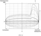
- Zone C it can be seen from Zone C that the damping force is increased during a rebound stroke by the high-pressure chamber 411 formed by the damping force forming member 101 and a fluid discharged from the high-pressure chamber 411, induced by changes in stroke caused by the movement of the piston 200. That is, a second damping force may be formed during a rebound stroke by the fluid in the high-pressure chamber 411 and the pressure of a fluid discharged from the high-pressure chamber 411.
- FIG. 12 shows that the stroke speed becomes faster toward the arrow. Specifically, a greater second damping force may be formed at a faster stroke speed, thereby providing better ride quality to the driver and effectively preventing shocks caused by full stroke travel.
- one side of the piston ring 600 is moved toward one side of the ring groove 510 by hydraulic pressure, in the direction of movement of the rod 300.
- One side of the piston ring 600 and one side wall of the ring groove 510 come into contact with each other, and the fluid beneath the piston ring 600 is drawn into the ring flow passageway 620 formed on one side of the piston ring 600.
- the other side wall of the ring groove 510 and the other side of the piston ring 600 are separated from each other with a gap between them, and the fluid beneath the piston ring 600 admitted through the gap passes through the space between the piston ring 600 and the stopper 500 and is drawn into the damping force forming member 101 between the rod guide 900 and the piston ring 600 or the upper part of the stopper 500 through the ring flow passageway 620.
- the above-mentioned gap serves as a bypass passage to allow the fluid to flow without getting stagnant, allowing the fluid to move to the ring flow passageway 620 without blockage.
- the stopper 500 may come out of the damping force forming member 101, and the piston 200 may move in a direction in which the volume of the second chamber 420 becomes smaller.
- the piston ring 600 may move in a direction in which the opening 611 becomes wider.
- valve of the piston 200 may be opened such that the fluid in the second chamber 420 is supplied to the first chamber 410.
- the damper apparatus 102 may control damping force by a simple structure using the damping force forming member 101.
- the damper apparatus 102 according to an embodiment of the present disclosure allows for effective tuning by configuring the damping force forming member 101, the stopper 500, and the piston ring 600, without the inner tube's complex structure for adjusting damping force or the configuration and structure of an elastic member.
- the damper apparatus 102 is capable of forming an additional damping force during a rebound stroke, thus making it effective in reducing shocks, and allows for absorbing abrupt shocks to a vehicle where the damper apparatus 102 is installed and provides better ride quality.
Landscapes
- Engineering & Computer Science (AREA)
- General Engineering & Computer Science (AREA)
- Mechanical Engineering (AREA)
- Fluid-Damping Devices (AREA)
Abstract
Description
- The present application claims priority to
Korean Patent Application No. 10-2023-0059793, filed May 09, 2023 - An embodiment of the present disclosure generally relates to a damping force forming member and a damper apparatus including the same, and, more particularly, relates to a damping force forming member that is capable of forming additional damping force during a rebound stroke, besides a damping force formed by a piston, and a damper apparatus including the same.
- Generally, a damper apparatus pressurizes a fluid in it in the event of an external shock and absorb the shock by the resistance of the fluid. Such a damper apparatus is installed in a vehicle to absorb abrupt shocks when the vehicle is moving, thereby providing better ride quality to the driver.
- The damper apparatus performs a compression stroke and a rebound stroke.
- In particular, when the rod extends to its maximum during the rebound stroke, shocks can occur.
- Thus, in the conventional art, the shape of the inside of a tube was altered in order to reduce such shocks during the rebound stroke.
- However, altering the inside of the tube requires a new process for manufacturing the tube. Also, when the performance of the damper apparatus is varied, such a tube needs to be replaced entirely or a new tube needs to be manufactured, and this makes tuning of the damper apparatus not an easy operation when the driver is required to do it or the vehicle specification entails it.
- Thus, there arises a need for a damper apparatus that performs a rebound stroke in a stable manner and can be easily tuned without hindering ride quality for the driver or the passengers.
- An embodiment of the present disclosure provides a damping force forming member that performs a rebound stroke in a stable manner and can be easily tuned, and a damper apparatus including the same.
- According to an exemplary embodiment of the present disclosure, there is provided a damping force forming member for forming a damping force, that is installed in a damper apparatus including a piston, a rod that supports the piston, and an inner tube in which a first chamber and a second chamber are separated by the piston placed therein, the damping force forming member comprising: a body supported by the inner tube, that is placed in such a manner that at least part of the inner circumference thereof faces the outer circumference of the rod and forms a damping force when the rod extends; a plurality of through-holes formed at intervals on the body; and a first flow passageway placed between the body and the inner tube, for guiding the movement of a fluid in the first chamber that has passed through the plurality of through-holes.
- Furthermore, the first flow passageway may be formed in one direction of the body.
- Furthermore, the plurality of through-holes may be disposed at intervals in one direction of the body.
- Furthermore, a plurality of first flow passageways may be disposed at intervals in a circumferential direction of the body.
- Furthermore, one of the plurality of first flow passageways may be formed in one region of the body where the plurality of through-holes are formed.
- Furthermore, the damping force forming member may further comprise a second flow passageway formed in a circumferential direction of the body by recessing the outer circumference of the body, for directing a fluid that has passed through the plurality of through-holes to move along the outer circumference of the body.
- Furthermore, when the rod extends, a pressurized fluid in the body may be discharged out of the body through the plurality of through-holes, and the damping force may be adjusted.
- According to an exemplary embodiment of the present disclosure, there is provided a damper apparatus comprising: a piston; a rod that supports the piston; and an inner tube having a fluid therein in which a first chamber and a second chamber are separated by the piston; a stopper spaced apart from the piston and supported by the rod; a piston ring supported by the stopper; and a damping force forming member, at least part of which is placed in the first chamber of the inner tube, and which forms a damping force through contact with the piston ring when the rod extends.
- Furthermore, the piston ring may include: a ring body placed in a circumferential direction of the stopper and having an opening so that both ends of the stopper are spaced apart from each other; and a ring flow passageway formed on one side of the ring body closer to the damping force forming member than the piston, for guiding the movement of fluid.
- Furthermore, when the inner circumference of the damping force forming member and the piston ring come into contact with each other, the ring body may move in a direction in which the opening becomes narrower, and a fluid in the damping force forming member may be restrained from passing through the stopper and moving toward the piston.
- Furthermore, the damping force forming member may include a through-hole that directs the fluid in the damping force forming member to be discharged between the outer circumference of the damping force forming member and the inner tube, when the inner circumference of the damping force forming member and the piston ring come into contact with each other.
- Furthermore, a plurality of through-holes may become smaller in diameter farther away from the piston.
- Furthermore, the damping force forming member may further include a first flow passageway placed parallel to one direction in which the plurality of through-holes are disposed, spaced apart from the inner tube.
- Furthermore, the damping force forming member may further include a second flow passageway recessed in a direction intersecting the first flow passageway, for guiding the movement of a fluid that has passed through the first flow passageway.
- Furthermore, the ring flow passageway may be formed by recessing one region of the ring body which is positioned further away from the piston than the ring flow passageway, and, when the rod contracts, may direct at least part of the fluid in the first chamber to pass through the stopper and move in a direction away from the piston.
- According to an embodiment of the present disclosure, a damping force forming member and a damper apparatus including the same are able to prevent shocks to the damper apparatus by using a hydraulic pressure when the rod moves in a direction in which it extends, thereby providing more comfortable ride quality to the driver.
- Specifically, additional damping force is provided through fluid resistance when the rod extends to a certain stroke or longer, thereby effectively preventing shocks caused by the full stroke travel of the rod.
-
-
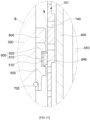
FIG. 1 depicts a damper apparatus including a damping force forming member according to an embodiment of the present disclosure. -
FIG. 2 depicts an exploded view of a damping force forming member and some components of a damper apparatus, according to an embodiment of the present disclosure. -
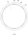
FIG. 3 depicts a damping force forming member according to an embodiment of the present disclosure. -
FIG. 4 depicts a configuration structure of a damping force forming member and an inner tube according to embodiments of the present disclosure. -
FIG. 5 depicts a partial exploded perspective view of the configuration structure of a damping force forming member and an inner tube according to an embodiment of the present disclosure. -
FIGS. 6 to 11 depict an operation process for a damper apparatus according to an embodiment of the present disclosure. -
FIG. 12 depicts a damping force diagram (F-V diagram) that changes with the velocity of a damper apparatus according to an embodiment of the present disclosure. - Embodiments of the present disclosure will be described in detail below with reference to the accompanying drawings so that those having ordinary knowledge in the art to which the present disclosure pertains can easily practice the present disclosure. The present disclosure may be implemented in various different forms, and is not limited to the embodiments described herein.
- It is noted that the drawings are schematic, and are not necessarily drawn to scale. The relative dimensions and ratios of the components in the drawings may be exaggerated or diminished in size for the sake of clarity and convenience, and such arbitrary dimensions are merely illustrative and are not limitative. Furthermore, the same reference symbol is used for the same structure, element or part shown in two or more drawings in order to represent similar features.
- The embodiments of the present disclosure specifically illustrate ideal embodiments of the present disclosure. As a result, various modifications of illustrations are expected. Accordingly, the embodiments are not limited to the specific forms of illustrated regions, and include, for example, the modifications of shapes resulting from manufacture.
- Hereinafter, a damping
force forming member 101 according to an embodiment of the present disclosure will be described with reference toFIGS. 1 to 5 . - The damping
force forming member 101 is installed in adamper apparatus 102 and forms a damping force. Specifically, thedamper apparatus 102 forms a damping force by a fluid in it. Also, thedamper apparatus 102 includes apiston 200, arod 300 that supports thepiston 200, and aninner tube 400 in which afirst chamber 410 and asecond chamber 420 are separated by thepiston 200. - As illustrated in
FIGS. 1 to 5 , the dampingforce forming member 101 according to an embodiment of the present disclosure includes abody 100, a plurality of through-holes 140, and afirst flow passageway 120. - The
body 100 is supported by theinner tube 400. Specifically, at least part of thebody 100 may be inserted and placed into thefirst chamber 410 of theinner tube 400. - Moreover, the
body 100 is placed in such a manner that at least part of the inner circumference faces the outer circumference of therod 300. Also, thebody 100 may form a damping force when therod 300 extends. Specifically, thebody 100 may be formed with acavity 110 so that therod 300 is inserted and placed at the center. When therod 300 extends to a certain stroke or longer, the fluid in thebody 100 may be pressurized, thereby forming a damping force. The fluid may be oil. - For example, the
body 100 may be roughly shaped like a "tube" through which thecavity 110 at the center is bored. That is, the outer diameter of thebody 100 may be relatively smaller than the inner diameter of theinner tube 400. - A plurality of through-
holes 140 may be bored at intervals on thebody 100. Specifically, a plurality of through-holes 140 may be bored on thebody 100 so that fluid is discharged toward the outer circumference of thebody 100. That is, the fluid in thecavity 110 inside thebody 100 may be discharged out of thebody 100 through the plurality of through-holes 140. - The
first flow passageway 120 may be placed between thebody 100 and theinner tube 400 and guide the flow of the fluid in thefirst chamber 410 that has passed through the plurality of through-holes 140. Specifically, thefirst flow passageway 120 may direct a fluid discharged out of thebody 100 through the plurality of through-holes 140 to move toward thepiston 200. - With this configuration, the damping
force forming member 101 according to an embodiment of the present disclosure may form a damping force as the space in thecavity 110 of thebody 100 forms a high-pressure chamber when therod 300 extends. - Moreover, the damping
force forming member 101 may form a damping force by allowing the space in thecavity 110 to form a high-pressure chamber during a rebound stroke of thedamper apparatus 102 by which therod 300 extends. - Accordingly, the damping
force forming member 101 according to an embodiment of the present disclosure is able to effectively prevent shocks transmitted to the damper apparatus by the damping force of the fluid when therod 300 moves in a direction in which it extends. - In addition, the
first flow passageway 120 according to an embodiment of the present disclosure may be formed in one direction of thebody 100, as illustrated inFIGS. 2 to 4 . - The
first flow passageway 120 may direct a fluid that has passed through the plurality of through-holes 140 and discharged between thebody 100 and theinner tube 400 to move in one direction of thebody 100. Specifically, thefirst flow passageway 120 may be formed on thebody 100. Also, one region on the outer circumference of thebody 100 where thefirst flow passageway 120 is formed may have a smaller outer diameter than the outer circumference of thebody 100. That is, the fluid may move along thefirst flow passageway 120, in one direction of thebody 100. - For example, the one direction of the
body 100 may be the length direction of thebody 100 which is roughly shaped like a "tube". - Thus, the fluid discharged out of the
body 100 through the plurality of through-holes 140 by thefirst flow passageway 120 may move effectively in one direction of thebody 100, and the damping force of the high-pressure chamber formed by the inside of thebody 100 may be adjusted. - Furthermore, the plurality of through-
holes 140 according to an embodiment of the present disclosure may be disposed at intervals in one direction of thebody 100, as illustrated inFIGS. 2 to 4 . - The plurality of through-
holes 140 may be disposed on thebody 100 at intervals in one direction of thebody 100. Also, the plurality of through-holes 140 may be disposed in parallel in one direction of thebody 100 in which thefirst flow passageway 120 is formed. - Moreover, a plurality of
first flow passageways 120 according to an embodiment of the present disclosure may be disposed at intervals in a circumferential direction of thebody 10, as illustrated inFIGS. 2 to 4 . - A plurality of
first flow passageways 120 may be formed at intervals on thebody 100 in a circumferential direction of thebody 100. Specifically, a plurality offirst flow passageways 120 may be disposed at intervals on the outer circumference in a circumferential direction of thebody 100, and the outer circumference of thebody 100 may be stepped or recessed so as to cause the fluid to move. - For example, the plurality of
first flow passageways 120 may be formed in the shape of a slit, and the outer circumference of thebody 100 having them may be roughly "polygonal". - In addition, one of the plurality of
first flow passageways 120 according to an embodiment of the present disclosure may be formed in one region of thebody 100 where the plurality of through-holes 140 are formed. - The plurality of through-
holes 140 may be disposed at intervals on one of the plurality offirst flow passageways 120 in the length direction of thebody 100. - That is, the fluid discharged through the plurality of through-
holes 140 may move along thefirst flow passageway 120 where the through-holes 140 are formed, among the plurality offirst flow passageways 120. - Furthermore, the damping
force forming member 101 according to an embodiment of the present disclosure may further include asecond flow passageway 130. - The
second flow passageway 130 may be recessed on thebody 100 in a circumferential direction of thebody 100. Also, thesecond flow passageway 130 may direct a fluid that has passed through the plurality of through-holes 140 to move along the outer circumference of thebody 100. Moreover, thesecond flow passageway 130 may allow the discharged fluid to be distributed to the otherfirst flow passageways 120 without getting stagnant in thefirst flow passageway 120 where the through-holes 140 are formed. - Specifically, the
second flow passageway 130 may effectively prevent a bottleneck phenomenon that may occur when the fluid that has moved to thefirst flow passageways 120 becomes stagnant. - In addition, according of an embodiment of the present disclosure, when the
rod 300 extends, the fluid in thebody 100 may be discharged out of thebody 100 through the plurality of through-holes 140, thereby adjusting the damping force. - During a rebound stroke of the
damper apparatus 102, therod 300, along with thepiston 200, moves in a direction in which the volume of the first chamber 310 becomes smaller, and the fluid remaining in the high-pressure chamber formed inside thebody 100 of the dampingforce forming member 101 may be discharged out of thebody 100 through the plurality of through-holes 140, thereby adjusting the damping force. - Specifically, the damping force may be adjusted according to the distance between the plurality of through-
holes 140 and the diameter of the plurality of through-holes 140. - For example, at least some of the plurality of through-
holes 140 may be spaced at different intervals from each other. - Accordingly, the damping force of the
damper apparatus 102 may be adjusted by altering the design of the dampingforce forming member 101 or replacing the dampingforce forming member 101 by another with an altered design. - Furthermore, a plurality of
second flow passageways 130 according to an embodiment of the present disclosure may be disposed at intervals on thebody 100, as illustrated inFIG. 2 to 5 . - The
second flow passageways 130 may be disposed at intervals on thebody 100 in the length direction of thebody 100. - Furthermore, the plurality of through-
holes 140 according to an embodiment of the present disclosure may have a smaller diameter as they become farther away from thepiston 200 in the length direction of thebody 100. - Since the through-
holes 140 have a smaller diameter as they become farther away from thepiston 200, the inside of thebody 100 forms a high-pressure chamber, and a damping force may be effectively formed and adjusted. - Hereinafter, the
damper apparatus 102 according to an embodiment of the present disclosure will be described with reference toFIGS. 1 to 11 . - As illustrated in
FIG. 1 , thedamper apparatus 102 according to an embodiment of the present disclosure includes apiston 200, arod 300, aninner tube 400, astopper 500, apiston ring 600, and a dampingforce forming member 101. - The
piston 200 includes a valve in it for opening and closing a flow passageway. The valve included in thepiston 200 is opened and closed by the pressure of a fluid generated by the movement of thepiston 200. - The
rod 300 supports thepiston 200. Specifically, thepiston 200 may be supported by therod 300, and thepiston 200 and therod 300 may be moved together. - The
inner tube 400 is hollow inside, and may be formed longitudinally in one direction. Also, a fluid for damping is stored inside theinner tube 400. Moreover, thepiston 200 is placed inside theinner tube 400 and separates thefirst chamber 410 and thesecond chamber 420. - Specifically, the volumes of the
first chamber 410 and thesecond chamber 420 may vary with the movement of thepiston 200. That is, as thepiston 200 moves in the length direction of theinner tube 400, the volumes of thefirst chamber 410 and thesecond chamber 420 may be varied. - The
stopper 500 is supported by therod 300. Also, thestopper 500 may be placed on therod 300 in the length direction of therod 300, spaced apart from thepiston 200. - The
piston ring 600 is supported by thestopper 500. Specifically, thestopper 500 is provided to limit the maximum stroke of therod 300. - At least part of the damping
force forming member 101 is placed within thefirst chamber 410 of theinner tube 400. Also, when therod 300 extends, the dampingforce forming member 101 may come into contact with thepiston ring 600 and form a damping force. Specifically, when the outer circumference of thepiston ring 600 comes into contact with an inner surface of the dampingforce forming member 101, a high-pressure chamber may be formed above thepiston ring 600 and inside the dampingforce forming member 101. - For example, the damping
force forming member 101 included in thedamper apparatus 102 according to an embodiment of the present disclosure may be identical to the above-described dampingforce forming member 101 according to an embodiment of the present disclosure. - Thus, in the
damper apparatus 102 according to an embodiment of the present disclosure, when therod 300 moves in a direction in which it extends outward of theinner tube 400 through a rebound stroke, thepiston ring 600 and the dampingforce forming member 101 may come into contact with each other, and a high-pressure chamber may be formed inside the dampingforce forming member 101, thereby forming a damping force for thedamper apparatus 102. - Furthermore, the
piston ring 600 of thedamper apparatus 102 according to an embodiment of the present disclosure may include aring body 610 and aring flow passageway 620, as illustrated inFIG. 2 . - The
ring body 610 may have anopening 611 so that both ends thereof are spaced apart from each other. Also, thering body 610 may be placed in a circumferential direction of thestopper 500. Specifically, thering body 610 may be roughly shaped like a partially open "circle" with anopening 611. - For example, the
ring body 610 may be formed from an elastically deformable material. That is, thering body 610 may be formed in a circumferential direction to include an elastically deformable material. - The
ring flow passageway 620 may be formed on one side of thering body 610 closer to the dampingforce forming member 101 than thepiston 200 is. Also, thering flow passageway 620 may guide the movement of fluid. - Specifically, the
ring flow passageway 620 may direct the fluid on the other side of thering body 610 to move toward one side of thering body 610. - The
ring flow passageway 620 may be formed by recessing one region of thering body 610 which is positioned further away from thepiston 200 than thering flow passageway 620. A plurality ofring flow passageways 620 may be formed in a circumferential direction of thepiston ring 600. - Moreover, the
ring flow passageway 620 may allow thepiston ring 600 to move in a direction in which thepiston ring 600 becomes farther away from the dampingforce forming member 101, inside the dampingforce forming member 101, and, when therod 300 contracts, may allow at least part of the fluid in thefirst chamber 410 to move in a direction opposite to the direction in which therod 300 contracts. Specifically, thering flow passageway 620 may allow at least part of the fluid in thefirst chamber 410 to pass through thestopper 500 and move in a direction away from thepiston 200, so that the fluid is supplied into the dampingforce forming member 101. - In addition, the
stopper 500 according to an embodiment of the present disclosure may include aring groove 510, as illustrated inFIG. 2 . - The
ring groove 510 may be formed in a circumferential direction in one region of the outer circumference of thestopper 500. Also, thering groove 510 may be recessed so as to support thepiston ring 600 and guide the movement of fluid. - Furthermore, when the inner circumference of the damping
force forming member 101 according to an embodiment of the present disclosure and thepiston ring 600 come into contact with each other, thering body 610 moves in a direction in which theopening 611 becomes narrower, and a fluid in the dampingforce forming member 101 may be restrained from passing through thestopper 500 and moving toward thepiston 200. - Specifically, both ends of the
ring body 610 become closer in a direction in which theopening 611 becomes narrower, and the other side of thepiston ring 600 comes into contact with the other side wall surface forming thering groove 510 and serves as a sealing in order to prevent the fluid in the dampingforce forming member 101 from passing through thestopper 500 and moving toward thepiston 200. Thus, the outer circumference of thepiston ring 600 and the inside of the dampingforce forming member 101 may remain sealed through surface contact. - That is, when the
rod 300 moves in a direction in which it extends outward of theinner tube 400 through a rebound stroke, toward a region where a plurality of through-holes 140 of the dampingforce forming member 101 are formed, thepiston ring 600 moves in a direction in which theopening 611 becomes narrower as thepiston ring 600 and the inner circumference of the dampingforce forming member 101 come into contact with each other, and the other side of thepiston ring 600 comes into contact with the other side wall surface forming thering groove 510 and prevents the fluid in the dampingforce forming member 101 from passing through the outer circumference of thepiston ring 600 and thestopper 500 and moving in a direction opposite to the direction of travel of therod 300. - In other words, when the
rod 300 moves in a direction in which it extends outward of theinner tube 400 through a rebound stroke, thepiston ring 600 serves as a sealing while elastically compressing the inner circumference of the dampingforce forming member 101, thereby causing the fluid in the dampingforce forming member 101 to move in one direction inside the dampingforce forming member 101 along the direction of travel of therod 300. - Incidentally, when the
rod 300 moves in a direction in which it extends outward of theinner tube 400 through a rebound stroke, as far as where the plurality of through-holes 140 of the dampingforce forming member 101 are not formed, or if the pressure in the dampingforce forming member 101 is too high, the high-pressure fluid in the dampingforce forming member 101 may cause some of the oil to be discharged through theopening 611 of thepiston ring 600. In this case, the fluid may be moved, not through a sealing-forming surface, but through thering flow passageway 620 and theopening 610, as the outer circumference of thepiston ring 600 and the dampingforce forming member 101 come into contact with each other. - That is, when the
rod 300 moves in a direction in which it extends outward of theinner tube 400 and a high pressure above a certain level is formed in the dampingforce forming member 101, thering flow passageway 620 and theopening 611 guide the flow of the high-pressure fluid in the dampingforce forming member 101 and the space above thestopper 500, and adjusts the pressure inside the dampingforce forming member 101, thereby effectively preventing damage to the dampingforce forming member 101 and thedamper apparatus 102. - Alternatively, when the
rod 300 moves in a direction in which it extends outward of theinner tube 400 through a rebound stroke, as far as where the plurality of through-holes 140 of the dampingforce forming member 101 are not formed, if the fluid in the dampingforce forming member 101 cannot be discharged through the plurality of through-holes 140, the fluid may be discharged through theopening 611, and the internal pressure may be adjusted. - Alternatively, after a rebound stroke, when the
piston ring 600 comes into contact with the inner circumference of the dampingforce forming member 101 and moves in a direction in which therod 300 contracts, one side of thepiston ring 600 where thering groove 510 is formed moves so as to become closer to one side wall surface forming thering groove 510, and the fluid beneath thepiston ring 600 on the inner circumference of the dampingforce forming member 101 may be supplied into the space above thepiston ring 600 in the dampingforce forming member 101 through thepiston ring 600, thering groove 510, and thering flow passageway 620, in a direction opposite to therod 300. - That is, once a compression stroke is performed in a direction in which the
rod 300 contracts, while thestopper 500 is placed inside the dampingforce forming member 101 by means of thering flow passageway 620, thepiston 200 may move in a direction in which the volume of thesecond chamber 420 becomes smaller. In this case, the fluid remaining beneath thestopper 500 may flow above thestopper 500 or thepiston ring 600, along with the movement of thestopper 500. - Moreover, the damping
force forming member 101 according to an embodiment of the present disclosure may include a through-hole 140. - The through-
hole 140 may be formed in the dampingforce forming member 101. Also, the through-hole 140 may direct the fluid in the dampingforce forming member 101 to be discharged between the outer circumference of the dampingforce forming member 101 and theinner tube 400, when the inner circumference of the dampingforce forming member 101 and thepiston ring 600 come into contact with each other. - Specifically, when the
rod 300 moves in a direction in which it extends outward of theinner tube 400 through a rebound stroke, the fluid in the dampingforce forming member 101 may be discharged through the through-hole 140. That is, when therod 300 moves in a direction in which it extends outward of theinner tube 400 through a rebound stroke, a damping force is formed as the inner circumference of the dampingforce forming member 101 and thepiston ring 600 come into contact with each other, and the fluid in the dampingforce forming member 101 may be discharged through the through-hole 140. - Thus, when the
rod 300 moves in a direction in which it extends outward of theinner tube 400 through a rebound stroke, the fluid in the high-pressure chamber inside the dampingforce forming member 101 may be discharged through the through-hole 140. - In addition, in the
damper apparatus 102 according to an embodiment of the present disclosure, a plurality of through-holes 140 with different diameters may be disposed at intervals in one direction of the dampingforce forming member 101. - A plurality of through-
holes 140 with different diameters may be formed on the dampingforce forming member 101. Also, the plurality of through-holes 140 may be disposed at intervals in one direction of the dampingforce forming member 101. - As for the requirements for the diameters and spacing of the through-
holes 140, design changes or adjustments may be made based on a damping force required for a vehicle where thedamper apparatus 102 is installed. - Furthermore, the plurality of through-
holes 140 according to an embodiment of the present disclosure may become smaller in diameter as they become farther away from thepiston 200. - The plurality of through-
holes 140, formed at intervals in one direction on the outer circumference of the dampingforce forming member 101, may become smaller in diameter farther away from thepiston 200. - Thus, when the
piston 200 moves toward the dampingforce forming member 101 and therod 300 moves in a direction in which it extends, the space between the inside of the dampingforce forming member 101 and thepiston ring 600 forms a high-pressure chamber, thereby generating a damping force, and the fluid in the dampingforce forming member 101 is discharged to the through-holes 140 as thepiston ring 600 moves, and the damping force may be adjusted. - Specifically, since the through-
holes 140 become smaller in diameter as they become farther away from thepiston 200, the damping force may be varied with respect to the movement of therod 300 in a direction in which it extends, as the inner circumference of the dampingforce forming member 101 and thepiston ring 600 placed on the outer circumference of thestopper 500 come into contact with each other. - Furthermore, the damping
force forming member 101 of thedamper apparatus 102 according to an embodiment of the present disclosure may further include afirst flow passageway 120. - The
first flow passageway 120 may be placed on the dampingforce forming member 101 in a direction parallel to one direction in which the plurality of through-holes 140 are disposed. Also, the outer circumference of the dampingforce forming member 101 where thefirst flow passageway 120 is formed may be spaced apart from the inner circumference of theinner tube 400. - Specifically, the outer surface of the damping
force forming member 101 where thefirst flow passageway 120 is formed may be recessed or stepped to allow the movement of fluid. - That is, the
first flow passageway 120 may direct the fluid discharged out of the dampingforce forming member 101 through the plurality of through-holes 140 to move in one direction of the dampingforce forming member 101. - Furthermore, the damping
force forming member 101 of thedamper apparatus 102 according to an embodiment of the present disclosure may further include asecond flow passageway 130. - The
second flow passageway 130 may be placed on the dampingforce forming member 101 in a direction intersecting thefirst flow passageway 120. Also, thesecond flow passageway 130 may cause a fluid that has passed through thefirst flow passageway 120 to move in a direction intersecting thefirst flow passageway 120, thereby preventing the fluid from getting stagnant on thefirst flow passageway 120. Moreover, thesecond flow passageway 130 may be formed by recessing the dampingforce forming member 101, thereby forming a space in which fluid moves. - For example, in a case where a plurality of
first flow passageways 120 are formed on the dampingforce forming member 101, thesecond flow passageway 130 may be formed in a direction intersecting the plurality offirst flow passageways 120 so that the fluid that has passed through the through-holes 140 moves to the plurality offirst flow passageways 120. That is, thesecond flow passageway 130 may allow the fluid discharged through the through-holes 140 to be distributed to the plurality offirst flow passageways 120. - Moreover, the length of the
ring groove 510 of thedamper apparatus 102 according to an embodiment of the present disclosure may be relatively greater than the length of thepiston ring 600. - The length of the
ring groove 510 parallel to the length direction of therod 300 may be relatively greater than the length of thepiston ring 600 parallel to the length direction of therod 300. - The
piston ring 600 placed on thering groove 510 may be moved along the length direction of thering groove 510. Specifically, thepiston ring 600 may be moved along the length direction of thering groove 510 in a direction in which therod 300 extends or contracts. By the lengthwise movement of thering groove 510, the flow of a fluid passing through thering flow passageway 620 may be selectively permitted or restricted. - In addition, the
first flow passageway 120 according to an embodiment of the present disclosure may have a larger area than the plurality of through-holes 140. - The
first flow passageway 120 may be formed in such a way as to guide the flow of a fluid discharged through the plurality of through-holes 140 and thereby cause the discharged fluid to move without stagnation. - Accordingly, the
first flow passageway 120 has a larger area than the plurality of through-holes 140, so that fluid moves without a bottleneck phenomenon in the space between theinner tube 400 and the dampingforce forming member 101. - For example, if there are a plurality of
first flow passageways 120, the plurality of through-holes 140 may have a larger area than the plurality offirst flow passageways 120. - Alternatively, the
second flow passageway 130 according to an embodiment of the present disclosure may have a larger area than the plurality of through-holes 140. - Since the
second flow passageway 130 has a larger area than the plurality of through-holes 140, it may cause a fluid to move in a direction that intersects the direction in which a discharged fluid moves to thefirst flow passageway 120. - For example, the area of the
first flow passageway 120 may be larger than or equal to the area of thesecond flow passageway 130. - Thus, the fluid that has passed through the plurality of through-
holes 140 may be moved through thefirst flow passageway 120 and thesecond flow passageway 130 without stagnation. - Furthermore, the
damper apparatus 102 according to an embodiment of the present disclosure may further include arod guide 900. - The
rod guide 900 is supported by one end of theinner tube 400, and may be movably supported by therod 300 inserted in it. - Moreover, when the
rod 300 moves, therod guide 900 may prevent the fluid in theinner tube 400 from being discharged to the outside along with the movement of therod 300. Specifically, at least part of therod guide 900 may be inserted into theinner tube 400. Also, at least part of therod guide 900 inserted into theinner tube 400 may be placed inside the dampingforce forming member 101. - A flange formed on one end of the body of the damping
force forming member 101 is supported by one end of theinner tube 400, and part of theinner tube 400 may be inserted into the dampingforce forming member 101. - Also, one end of the damping
force forming member 101 may be placed between theinner tube 400 and one end of therod guide 900. - In addition, the
damper apparatus 102 according to an embodiment may further include ashock absorbing member 800. - The
shock absorbing member 800 is placed on the outer circumference of therod 300, and may be located farther away from thepiston 200 than thestopper 500 is. Specifically, one side of theshock absorbing member 800 may be supported by an upper part of thestopper 500. - The
shock absorbing member 800 may absorb shocks created by contact between thestopper 500 and therod guide 900 during a rebound stroke. Also, theshock absorbing member 800 may reduce shocks between therod guide 900 and thestopper 500 when the rod 3400 is moved to its full stroke during a rebound stroke. That is, theshock absorbing member 800 may prevent contact between thestopper 500 and therod guide 900 and therefore effectively prevent damage to thedamper apparatus 102 caused by a collision between them or prevent a resulting shock from being transmitted to the vehicle where thedamper apparatus 102 is installed. - For example, the
shock absorbing member 800 may be formed by including an elastically deformable material. - Furthermore, the
damper apparatus 102 according to an embodiment of the present disclosure may further include astop ring 700. - The
stop ring 700 may be placed between therod 300 and thestopper 500, so that thestopper 500 is stably supported by therod 300. Also, thestop ring 700 may prevent thestopper 500 from moving away from its installation position on therod 300 toward thepiston 200. - Specifically, a space where the
stop ring 700 can be installed may be formed on the inner circumference of thestopper 500. - Furthermore, the
damper apparatus 102 according to an embodiment may further include anouter tube 450. - The
outer tube 450 is placed in such a way that at least part thereof encloses theinner tube 400, and may form the exterior of thedamper apparatus 102. Specifically, theouter tube 450 may be made relatively longer than theinner tube 400. Also, theinner tube 400 and theouter tube 450 may be placed with a gap between them. - Hereinafter, an operation process of the
damper apparatus 102 according to an embodiment of the present disclosure will be described with reference toFIGS. 1 to 12 . - As illustrated in
FIGS. 1 to 3 andFIG. 6 , thepiston 200 and therod 300 are moved in a direction in which the volume of thefirst chamber 410 becomes smaller. Therod 300 is moved in a direction in which it extends outward of theinner tube 400. That is, thedamper apparatus 102 performs a rebound stroke. - In this case, a fluid stored in the
first chamber 410 causes the valve of thepiston 200 to open and is drawn into thesecond chamber 420. That is, thepiston 200 moves in a direction in which the volume of thefirst chamber 410 become smaller, and a first damping force is formed by the hydraulic pressure of the fluid. - As illustrated in
FIGS. 1 to 3 andFIGS. 7 and8 , when therod 300 is moved to a certain stroke or longer, thestopper 500 andpiston ring 600 supported by therod 300 move into the dampingforce forming member 101. - The other side of the
piston ring 600 is moved toward the other side of thering groove 510 by the hydraulic pressure, in the direction of movement of therod 300. - The outer circumference of the
piston ring 600 comes into contact with the inner circumference of thebody 100 of the dampingforce forming member 101, and thepiston 600 moves in a direction in which theopening 611 becomes narrower. That is, thepiston ring 600 moves toward thering groove 510, and the other side of thepiston ring 600 comes into contact with the other side wall of thering groove 510 which thepiston ring 600 is facing, and serves as a sealing. - In this instance, a high-
pressure chamber 411 is formed inside the dampingforce forming member 101 between therod guide 900 and thepiston ring 600 or the upper part of thestopper 500. That is, thedamper apparatus 102 forms a damping force by the hydraulic pressure of the fluid in the high-pressure chamber 411. - Thus, during a rebound stroke performed by the
damper apparatus 102, when the piston ring 60 or thestopper 500 goes into the dampingforce forming member 101, a second damping force is formed. - In other words, the other side of the
piston ring 600 and the other side wall of thering groove 510 come into contact with each other, and thepiston ring 600 moves toward the center of thering groove 510, thereby preventing the fluid above thepiston ring 600 from flowing below thepiston ring 600 and effectively forming a second damping force by means of the high-pressure chamber 411. - Moreover, the
rod 300 continues moving as the outer circumference of thepiston ring 600 comes into contact with the inner circumference of thebody 100 of the dampingforce forming member 101. In this case, the fluid in the high-pressure chamber 411 is discharged through the through-holes 140. Also, the discharged fluid may be moved between the dampingforce forming member 101 and theinner tube 400 through thefirst flow passageway 120 and thesecond flow passageway 130. - Accordingly, when the
rod 300 moves in a direction in which it extends, a damping force may be formed by the high-pressure chamber 411 and the pressure of a fluid discharged from the high-pressure chamber 411 through the through-holes 140. Thus, thedamper apparatus 102 may effectively provide a damping force such as a conventional damper apparatus has never achieved before. - Specifically, as illustrated in
FIG. 12 , it can be seen from Zone C that the damping force is increased during a rebound stroke by the high-pressure chamber 411 formed by the dampingforce forming member 101 and a fluid discharged from the high-pressure chamber 411, induced by changes in stroke caused by the movement of thepiston 200. That is, a second damping force may be formed during a rebound stroke by the fluid in the high-pressure chamber 411 and the pressure of a fluid discharged from the high-pressure chamber 411. -
FIG. 12 shows that the stroke speed becomes faster toward the arrow. Specifically, a greater second damping force may be formed at a faster stroke speed, thereby providing better ride quality to the driver and effectively preventing shocks caused by full stroke travel. - Accordingly, even if a rebound stroke is performed at a high speed, the driver can enjoy a comfortable ride because of the greater second damping force.
- As illustrated in
FIGS. 1 to 3 andFIGS. 9 and10 , when a compression stroke is started after completion of the above-described rebound stroke, thestopper 500 positioned in the dampingforce forming member 101 moves in a direction in which therod 300 extends and contracts. - In this instance, one side of the
piston ring 600 is moved toward one side of thering groove 510 by hydraulic pressure, in the direction of movement of therod 300. One side of thepiston ring 600 and one side wall of thering groove 510 come into contact with each other, and the fluid beneath thepiston ring 600 is drawn into thering flow passageway 620 formed on one side of thepiston ring 600. - Specifically, as illustrated in
FIG. 10 , the other side wall of thering groove 510 and the other side of thepiston ring 600 are separated from each other with a gap between them, and the fluid beneath thepiston ring 600 admitted through the gap passes through the space between thepiston ring 600 and thestopper 500 and is drawn into the dampingforce forming member 101 between therod guide 900 and thepiston ring 600 or the upper part of thestopper 500 through thering flow passageway 620. - That is, the above-mentioned gap serves as a bypass passage to allow the fluid to flow without getting stagnant, allowing the fluid to move to the
ring flow passageway 620 without blockage. - As illustrated in
FIG. 11 , when therod 300 continues moving in a direction in which therod 300 extends and contracts, thestopper 500 may come out of the dampingforce forming member 101, and thepiston 200 may move in a direction in which the volume of thesecond chamber 420 becomes smaller. - When the contact between the outer circumference of the
piston ring 600 and the inner circumference of the dampingforce forming member 101 is released, thepiston ring 600 may move in a direction in which theopening 611 becomes wider. - Also, the valve of the
piston 200 may be opened such that the fluid in thesecond chamber 420 is supplied to thefirst chamber 410. - With this configuration, the
damper apparatus 102 according to an embodiment of the present disclosure may control damping force by a simple structure using the dampingforce forming member 101. Specifically, thedamper apparatus 102 according to an embodiment of the present disclosure allows for effective tuning by configuring the dampingforce forming member 101, thestopper 500, and thepiston ring 600, without the inner tube's complex structure for adjusting damping force or the configuration and structure of an elastic member. - Therefore, the
damper apparatus 102 according to an embodiment of the present disclosure is capable of forming an additional damping force during a rebound stroke, thus making it effective in reducing shocks, and allows for absorbing abrupt shocks to a vehicle where thedamper apparatus 102 is installed and provides better ride quality. - Although exemplary embodiments of the present disclosure are described above with reference to the accompanying drawings, it is understood that those skilled in the art may embody the technical configuration in other specific forms without changing the technical spirits and essential features of the present disclosure.
- Therefore, it should be understood that the embodiments described above are exemplary and not restrictive in all aspects, and the scope of the present disclosure is defined by the appended claims rather than the above specific descriptions. It should be interpreted that all the changed and modified forms derived from the meaning, scope and equivalent concepts of the claims are included in the scope of the present disclosure.
Claims (15)
- A damping force forming member (101) for forming a damping force, that is installed in a damper apparatus (102) including a piston (200), a rod (300) that supports the piston (200), and an inner tube (400) in which a first chamber (410) and a second chamber (420) are separated by the piston (200) placed therein, the damping force forming member (101) comprising:a body (100) supported by the inner tube (400), that is placed in such a manner that at least part of the inner circumference thereof faces the outer circumference of the rod (300) and forms a damping force when the rod (300) extends;a plurality of through-holes (140) formed at intervals on the body (100); anda first flow passageway (120) placed between the body (100) and the inner tube (400), for guiding the movement of a fluid in the first chamber (410) that has passed through the plurality of through-holes (140).
- The damping force forming member (101) of claim 1, wherein the first flow passageway (120) is formed in one direction of the body (100).
- The damping force forming member (101) of claim 2, wherein the plurality of through-holes (140) are disposed at intervals in one direction of the body (100).
- The damping force forming member (101) of claim 2 or 3, wherein a plurality of first flow passageways (120) are disposed at intervals in a circumferential direction of the body (100).
- The damping force forming member (101) of claim 4, wherein one of the plurality of first flow passageways (120) is formed in one region of the body (100) where the plurality of through-holes (140) are formed.
- The damping force forming member (101) of any one of claims 1 to 5, further comprising a second flow passageway (130) formed in a circumferential direction of the body (100) by recessing the outer circumference of the body (100), for directing a fluid that has passed through the plurality of through-holes (140) to move along the outer circumference of the body (100).
- The damping force forming member (101) of any one of claims 1 to 6, wherein, when the rod (300) extends, a pressurized fluid in the body (100) is discharged out of the body (100) through the plurality of through-holes (140), and the damping force is adjusted.
- A damper apparatus (102) comprising:a piston (200);a rod (300) that supports the piston (200);an inner tube (400) having a fluid therein in which a first chamber (410) and a second chamber (420) are separated by the piston (200);a stopper (500) spaced apart from the piston (200) and supported by the rod (300);a piston ring (600) supported by the stopper (500); anda damping force forming member (101), at least part of which is placed in the first chamber (410) of the inner tube (400), and which forms a damping force through contact with the piston ring (600) when the rod (300) extends.
- The damper apparatus (102) of claim 8, wherein the piston ring (600) includes:a ring body (610) placed in a circumferential direction of the stopper (500) and having an opening (611) so that both ends of the stopper (500) are spaced apart from each other; anda ring flow passageway (620) formed on one side of the ring body (610) closer to the damping force forming member (101) than the piston (200), for guiding the movement of fluid.
- The damper apparatus (102) of claim 9, wherein, when the inner circumference of the damping force forming member (101) and the piston ring (600) come into contact with each other, the ring body (610) moves in a direction in which the opening (611) becomes narrower, and a fluid in the damping force forming member (101) is restrained from passing through the stopper (500) and moving toward the piston (200).
- The damper apparatus (102) of any one of claims 8 to 10, wherein the damping force forming member (101) includes a through-hole (140) that directs the fluid in the damping force forming member (101) to be discharged between the outer circumference of the damping force forming member (101) and the inner tube (400), when the inner circumference of the damping force forming member (101) and the piston ring (600) come into contact with each other.
- The damper apparatus (102) of claim 11, wherein a plurality of through-holes (140) become smaller in diameter farther away from the piston (200).
- The damper apparatus (102) of claim 12, wherein the damping force forming member (101) further includes a first flow passageway (120) placed parallel to one direction in which the plurality of through-holes (140) are disposed, spaced apart from the inner tube (400).
- The damper apparatus (102) of claim 13, wherein the damping force forming member (101) further includes a second flow passageway (130) recessed in a direction intersecting the first flow passageway (120), for guiding the movement of a fluid that has passed through the first flow passageway (120).
- The damper apparatus (102) of claim 9 or 10, wherein the ring flow passageway (620) is formed by recessing one region of the ring body (610) which is positioned further away from the piston (200) than the ring flow passageway (620), and, when the rod (300) contracts, directs at least part of the fluid in the first chamber (410) to pass through the stopper (500) and move in a direction away from the piston (200).
Applications Claiming Priority (1)
| Application Number | Priority Date | Filing Date | Title |
|---|---|---|---|
| KR1020230059793A KR20240162777A (en) | 2023-05-09 | 2023-05-09 | Damping force forming member and damper apparatus including the same |
Publications (2)
| Publication Number | Publication Date |
|---|---|
| EP4484788A2 true EP4484788A2 (en) | 2025-01-01 |
| EP4484788A3 EP4484788A3 (en) | 2025-07-23 |
Family
ID=91067310
Family Applications (1)
| Application Number | Title | Priority Date | Filing Date |
|---|---|---|---|
| EP24174685.8A Pending EP4484788A3 (en) | 2023-05-09 | 2024-05-07 | Damper force forming member and damper apparatus including the same |
Country Status (4)
| Country | Link |
|---|---|
| US (1) | US20240376958A1 (en) |
| EP (1) | EP4484788A3 (en) |
| KR (1) | KR20240162777A (en) |
| CN (1) | CN118934878A (en) |
Family Cites Families (6)
| Publication number | Priority date | Publication date | Assignee | Title |
|---|---|---|---|---|
| GB2158181B (en) * | 1984-04-30 | 1988-11-02 | Volzh Ob Proizv | Hydraulic telescopic shock-absorber with a rebound bumper |
| DE3907531C2 (en) * | 1988-03-21 | 1999-09-09 | Tenneco Automotive Inc | Vibration dampers for motor vehicles |
| DE102004008956A1 (en) * | 2004-02-24 | 2005-09-01 | Volkswagen Ag | Hydraulic damper with dampened end stop has a radial extension of a flow restricting sleeve to provide a hydraulic connection to reduce pressure peaks |
| US20120090931A1 (en) * | 2010-10-15 | 2012-04-19 | Olaf Krazewski | Shock absorber |
| DE102015223581A1 (en) * | 2015-11-27 | 2017-06-01 | Volkswagen Aktiengesellschaft | Vibration damper with hydraulic cable stop |
| CN113915279B (en) * | 2021-10-09 | 2023-02-24 | 北京京西重工有限公司 | Hydraulic damper |
-
2023
- 2023-05-09 KR KR1020230059793A patent/KR20240162777A/en active Pending
- 2023-10-13 US US18/380,006 patent/US20240376958A1/en active Pending
-
2024
- 2024-05-07 EP EP24174685.8A patent/EP4484788A3/en active Pending
- 2024-05-08 CN CN202410560794.0A patent/CN118934878A/en active Pending
Also Published As
| Publication number | Publication date |
|---|---|
| EP4484788A3 (en) | 2025-07-23 |
| KR20240162777A (en) | 2024-11-18 |
| CN118934878A (en) | 2024-11-12 |
| US20240376958A1 (en) | 2024-11-14 |
Similar Documents
| Publication | Publication Date | Title |
|---|---|---|
| US12031606B2 (en) | Shock absorber | |
| KR100894798B1 (en) | Shock absorber | |
| US9657803B2 (en) | Hydraulic damper with a hydraulic stop arrangement | |
| US11773941B2 (en) | Hydraulic vibration damper having a rebound stop and a compression stop | |
| KR101806755B1 (en) | Shock absorber | |
| US11686367B2 (en) | Hydraulic damper and a piston for the hydraulic damper assembly | |
| JP5183096B2 (en) | Shock absorber check valve | |
| CN103671674B (en) | Shock absorber | |
| WO2019239721A1 (en) | Pressure shock absorber | |
| US11542999B2 (en) | Valve and shock absorber | |
| US5927448A (en) | Shock absorber | |
| US20190001783A1 (en) | Damper With Volume Reducing Insert | |
| KR102944731B1 (en) | Frequency sensitive shock absorber | |
| KR101272755B1 (en) | Shock absorber | |
| KR20180050359A (en) | buffer | |
| JP2014092181A (en) | Pressure buffering device | |
| US20240376958A1 (en) | Damper force forming member and damper apparatus including the same | |
| WO2023120576A1 (en) | Damping force generation device | |
| EP1898119A2 (en) | Valve structure | |
| CN101782126B (en) | Rod guide for a shock absorber | |
| EP1898118A1 (en) | Valve structure | |
| KR101761867B1 (en) | Damping force variable shock absorber | |
| KR102838972B1 (en) | Frequency sensitive type shock absorber | |
| US20260098570A1 (en) | Body valve assembly and shock absorber with the same | |
| KR100880821B1 (en) | Shock absorber |
Legal Events
| Date | Code | Title | Description |
|---|---|---|---|
| PUAI | Public reference made under article 153(3) epc to a published international application that has entered the european phase |
Free format text: ORIGINAL CODE: 0009012 |
|
| STAA | Information on the status of an ep patent application or granted ep patent |
Free format text: STATUS: REQUEST FOR EXAMINATION WAS MADE |
|
| 17P | Request for examination filed |
Effective date: 20240507 |
|
| AK | Designated contracting states |
Kind code of ref document: A2 Designated state(s): AL AT BE BG CH CY CZ DE DK EE ES FI FR GB GR HR HU IE IS IT LI LT LU LV MC ME MK MT NL NO PL PT RO RS SE SI SK SM TR |
|
| PUAL | Search report despatched |
Free format text: ORIGINAL CODE: 0009013 |
|
| AK | Designated contracting states |
Kind code of ref document: A3 Designated state(s): AL AT BE BG CH CY CZ DE DK EE ES FI FR GB GR HR HU IE IS IT LI LT LU LV MC ME MK MT NL NO PL PT RO RS SE SI SK SM TR |
|
| RIC1 | Information provided on ipc code assigned before grant |
Ipc: F16F 9/346 20060101AFI20250618BHEP Ipc: F16F 9/49 20060101ALI20250618BHEP |