EP4484779A1 - Hub unit bearing - Google Patents
Hub unit bearing Download PDFInfo
- Publication number
- EP4484779A1 EP4484779A1 EP22928834.5A EP22928834A EP4484779A1 EP 4484779 A1 EP4484779 A1 EP 4484779A1 EP 22928834 A EP22928834 A EP 22928834A EP 4484779 A1 EP4484779 A1 EP 4484779A1
- Authority
- EP
- European Patent Office
- Prior art keywords
- outer ring
- vehicle body
- peripheral surface
- body mounting
- mounting flange
- Prior art date
- Legal status (The legal status is an assumption and is not a legal conclusion. Google has not performed a legal analysis and makes no representation as to the accuracy of the status listed.)
- Pending
Links
Images


Classifications
-
- B—PERFORMING OPERATIONS; TRANSPORTING
- B60—VEHICLES IN GENERAL
- B60B—VEHICLE WHEELS; CASTORS; AXLES FOR WHEELS OR CASTORS; INCREASING WHEEL ADHESION
- B60B27/00—Hubs
- B60B27/0078—Hubs characterised by the fixation of bearings
-
- F—MECHANICAL ENGINEERING; LIGHTING; HEATING; WEAPONS; BLASTING
- F16—ENGINEERING ELEMENTS AND UNITS; GENERAL MEASURES FOR PRODUCING AND MAINTAINING EFFECTIVE FUNCTIONING OF MACHINES OR INSTALLATIONS; THERMAL INSULATION IN GENERAL
- F16C—SHAFTS; FLEXIBLE SHAFTS; ELEMENTS OR CRANKSHAFT MECHANISMS; ROTARY BODIES OTHER THAN GEARING ELEMENTS; BEARINGS
- F16C33/00—Parts of bearings; Special methods for making bearings or parts thereof
- F16C33/30—Parts of ball or roller bearings
- F16C33/58—Raceways; Race rings
- F16C33/583—Details of specific parts of races
- F16C33/586—Details of specific parts of races outside the space between the races, e.g. end faces or bore of inner ring
-
- F—MECHANICAL ENGINEERING; LIGHTING; HEATING; WEAPONS; BLASTING
- F16—ENGINEERING ELEMENTS AND UNITS; GENERAL MEASURES FOR PRODUCING AND MAINTAINING EFFECTIVE FUNCTIONING OF MACHINES OR INSTALLATIONS; THERMAL INSULATION IN GENERAL
- F16C—SHAFTS; FLEXIBLE SHAFTS; ELEMENTS OR CRANKSHAFT MECHANISMS; ROTARY BODIES OTHER THAN GEARING ELEMENTS; BEARINGS
- F16C33/00—Parts of bearings; Special methods for making bearings or parts thereof
- F16C33/30—Parts of ball or roller bearings
- F16C33/58—Raceways; Race rings
- F16C33/64—Special methods of manufacture
-
- B—PERFORMING OPERATIONS; TRANSPORTING
- B60—VEHICLES IN GENERAL
- B60B—VEHICLE WHEELS; CASTORS; AXLES FOR WHEELS OR CASTORS; INCREASING WHEEL ADHESION
- B60B27/00—Hubs
- B60B27/0078—Hubs characterised by the fixation of bearings
- B60B27/0084—Hubs characterised by the fixation of bearings caulking to fix inner race
-
- F—MECHANICAL ENGINEERING; LIGHTING; HEATING; WEAPONS; BLASTING
- F16—ENGINEERING ELEMENTS AND UNITS; GENERAL MEASURES FOR PRODUCING AND MAINTAINING EFFECTIVE FUNCTIONING OF MACHINES OR INSTALLATIONS; THERMAL INSULATION IN GENERAL
- F16C—SHAFTS; FLEXIBLE SHAFTS; ELEMENTS OR CRANKSHAFT MECHANISMS; ROTARY BODIES OTHER THAN GEARING ELEMENTS; BEARINGS
- F16C19/00—Bearings with rolling contact, for exclusively rotary movement
- F16C19/02—Bearings with rolling contact, for exclusively rotary movement with bearing balls essentially of the same size in one or more circular rows
- F16C19/14—Bearings with rolling contact, for exclusively rotary movement with bearing balls essentially of the same size in one or more circular rows for both radial and axial load
- F16C19/18—Bearings with rolling contact, for exclusively rotary movement with bearing balls essentially of the same size in one or more circular rows for both radial and axial load with two or more rows of balls
- F16C19/181—Bearings with rolling contact, for exclusively rotary movement with bearing balls essentially of the same size in one or more circular rows for both radial and axial load with two or more rows of balls with angular contact
- F16C19/183—Bearings with rolling contact, for exclusively rotary movement with bearing balls essentially of the same size in one or more circular rows for both radial and axial load with two or more rows of balls with angular contact with two rows at opposite angles
- F16C19/184—Bearings with rolling contact, for exclusively rotary movement with bearing balls essentially of the same size in one or more circular rows for both radial and axial load with two or more rows of balls with angular contact with two rows at opposite angles in O-arrangement
- F16C19/186—Bearings with rolling contact, for exclusively rotary movement with bearing balls essentially of the same size in one or more circular rows for both radial and axial load with two or more rows of balls with angular contact with two rows at opposite angles in O-arrangement with three raceways provided integrally on parts other than race rings, e.g. third generation hubs
-
- F—MECHANICAL ENGINEERING; LIGHTING; HEATING; WEAPONS; BLASTING
- F16—ENGINEERING ELEMENTS AND UNITS; GENERAL MEASURES FOR PRODUCING AND MAINTAINING EFFECTIVE FUNCTIONING OF MACHINES OR INSTALLATIONS; THERMAL INSULATION IN GENERAL
- F16C—SHAFTS; FLEXIBLE SHAFTS; ELEMENTS OR CRANKSHAFT MECHANISMS; ROTARY BODIES OTHER THAN GEARING ELEMENTS; BEARINGS
- F16C2220/00—Shaping
- F16C2220/40—Shaping by deformation without removing material
- F16C2220/46—Shaping by deformation without removing material by forging
-
- F—MECHANICAL ENGINEERING; LIGHTING; HEATING; WEAPONS; BLASTING
- F16—ENGINEERING ELEMENTS AND UNITS; GENERAL MEASURES FOR PRODUCING AND MAINTAINING EFFECTIVE FUNCTIONING OF MACHINES OR INSTALLATIONS; THERMAL INSULATION IN GENERAL
- F16C—SHAFTS; FLEXIBLE SHAFTS; ELEMENTS OR CRANKSHAFT MECHANISMS; ROTARY BODIES OTHER THAN GEARING ELEMENTS; BEARINGS
- F16C2326/00—Articles relating to transporting
- F16C2326/01—Parts of vehicles in general
- F16C2326/02—Wheel hubs or castors
-
- F—MECHANICAL ENGINEERING; LIGHTING; HEATING; WEAPONS; BLASTING
- F16—ENGINEERING ELEMENTS AND UNITS; GENERAL MEASURES FOR PRODUCING AND MAINTAINING EFFECTIVE FUNCTIONING OF MACHINES OR INSTALLATIONS; THERMAL INSULATION IN GENERAL
- F16C—SHAFTS; FLEXIBLE SHAFTS; ELEMENTS OR CRANKSHAFT MECHANISMS; ROTARY BODIES OTHER THAN GEARING ELEMENTS; BEARINGS
- F16C33/00—Parts of bearings; Special methods for making bearings or parts thereof
- F16C33/30—Parts of ball or roller bearings
- F16C33/58—Raceways; Race rings
- F16C33/581—Raceways; Race rings integral with other parts, e.g. with housings or machine elements such as shafts or gear wheels
Definitions
- the present invention relates to a hub unit bearing for rotatably supporting a wheel of an automobile with respect to a suspension device.
- an outer ring of a hub unit bearing formed by forging is fastened and fixed to a knuckle by bolting from an inboard side of the knuckle when an insertion hole for inserting a knuckle bolt is a female screw, and is fastened and fixed to the knuckle by bolting from an outboard side when the insertion hole is a cylindrical hole.
- a hub wheel 101 includes a wheel mounting flange 102 extending radially outward from a cylindrical portion, and a wheel 105 and the hub wheel 101 are fixed to a hub bolt 103 inserted into a flange locking hole 104.
- an outer ring 111 includes a vehicle body mounting flange 114 extending radially outward from an outer periphery of the cylindrical portion 112, and the outer ring 111 and a knuckle 117 are fixed by fastening a knuckle bolt 115 inserted into a flange locking hole 116, which is a cylindrical hole, to the knuckle 117.
- Patent Literature 2 it is described that a rolling fatigue life of an outer ring raceway portion is improved by forging a metal material having high cleanliness so as to be exposed to a double row outer ring raceway portion of. Further, in Patent Literature 2, by performing forging molding so that a flash is emitted to an outer peripheral surface on an inboard side of the flange, a deformation resistance of an inboard side portion of the flange at the time of forging is lowered, a radius of curvature of a corner R portion on the inboard side becomes small, and a removal amount in finish cutting is reduced.
- the present invention has been made in view of the above-described problems, and an object thereof is to provide a hub unit bearing that can ensure a large area of an outboard side surface of the vehicle body mounting flange while maintaining the strength achieved by forging, without performing cutting on the outboard cylindrical portion of the outer ring.
- a large area of an outboard side surface of the vehicle body mounting flange can be ensured while maintaining strength achieved by forging, without performing cutting on the outboard cylindrical portion of the outer ring.
- outboard side in relation to an axial direction refers to a left side in FIG. 1 , which is an outer side in a width direction of a vehicle body when assembled to an automobile, and conversely, a right side in FIG. 1 , which is a center side in the width direction of the vehicle body, is referred to as the "inboard side" in the axial direction.
- a hub unit bearing 10 is for a driven wheel, and includes an outer ring 20, a hub 30, a plurality of rolling elements 40, a seal ring 50, and a cap 60.
- the outer ring 20 includes a cylindrical portion 22 having a double row outer ring raceways 21a and 21b on an inner peripheral surface, an entire peripheral flange 23 formed over an entire outer periphery at an axially middle portion of the cylindrical portion 22, and four vehicle body mounting flanges 24 extending radially outward from positions spaced apart from each other in a circumferential direction of the entire peripheral flange 23.
- the number of vehicle body mounting flanges 24 is not limited to four, and may be, for example, three.
- the vehicle body mounting flanges 24 are each formed with an insertion hole 26 through which a knuckle bolt 25 is inserted.
- the outer ring 20 does not rotate while supported by a knuckle 11 by coupling and fixing the vehicle body mounting flange 24 to the knuckle 11 of a suspension device through the knuckle bolt 25.
- the hub 30 is formed by coupling a hub wheel 31 and an inner ring 32, and is disposed coaxially (concentrically) with the outer ring 20 on an inner diameter side of the outer ring 20.
- the hub wheel 31 is provided with a wheel mounting flange 33 having a circular ring shape and extending radially outward at a portion located further outboard (on the left side in FIG. 1 ) than an end portion of the outer ring 20 on the outboard side and for supporting and fixing a braking rotary member such as a wheel (driven wheel) and a disc rotor.
- a stud bolt (not shown) is serrated and fitted into each of insertion holes 34 provided in the wheel mounting flange 33 to fix the braking rotary member (not shown) such as the wheel (driven wheel) and the disc rotor. Furthermore, the wheel mounting flange 33 is provided with a work hole 38 at a position corresponding to the insertion hole 26 of the vehicle body mounting flange 24, into which a fastening tool (for example, a socket) for fastening the knuckle bolt 25 can be inserted.
- a fastening tool for example, a socket
- an inner ring raceway 3 5a on the outboard side is provided on the outer peripheral surface of the hub wheel 31 in a portion opposing the outer ring raceway 21a on the outboard side provided on the inner peripheral surface of the outer ring 20.
- a small diameter step portion 36 is provided on the outer peripheral surface of the hub wheel 31 at an inboard end portion opposite the outer ring raceway 21b on the inboard side provided on the inner peripheral surface of the outer ring 20.
- An inner ring raceway 35b on the inboard side is provided on the outer peripheral surface of the inner ring 32, and the inner ring 32 is positioned and fixed in the axial direction by a crimp portion 37 formed by crimping the inboard end portion of the hub wheel 31 radially outward in a state in which the inner ring 32 is fitted and fixed to the small diameter step portion 36 of the hub wheel 31 by interference fit.
- a pitch circle diameter PCD1 of the plurality of work holes 38 is the same as a pitch circle diameter PCD2 of the plurality of insertion holes 26, and a diameter D3 of an inscribed circle of the plurality of work holes 38 has a size equal to or larger than a diameter D1 of an outer peripheral surface of an outboard cylindrical portion 22A. Accordingly, the fastening tool for fastening the knuckle bolt 25 can be easily inserted into the work hole 38 without interfering with the cylindrical portion 22, and workability is improved.
- a plurality of rolling elements 40 are rotatably provided between the outer ring raceway 21a and the inner ring raceway 35a on the outboard side and between the outer ring raceway 21b and the inner ring raceway 35b on the inboard side while being held by a holder 41.
- balls are used as the rolling elements 40, but in the case of a rolling bearing unit for supporting wheels of an automobile, which is heavy, tapered rollers may be used instead of the balls.
- the seal ring 50 closes an opening of an outboard end of an internal space 42 in which the plurality of rolling elements 40 are provided, which is present between the inner peripheral surface of the outer ring 20 and the outer peripheral surface of the hub 30, in a state in which the seal ring 50 is supported and fixed to an outboard end portion of the outer ring 20.
- the cap 60 is formed in a bottomed cylindrical shape and closes an opening at an inboard end of the outer ring 20 in a state assembled to the inboard end portion of the outer ring 20.
- the encoder 12 is fitted and fixed to the inboard end portion of the inner ring 32 of the hub 30, and a sensor unit (not shown) is assembled to a holding portion 61 of the cap 60.
- a detection portion of the sensor unit is brought close to and opposite a detection target surface of the encoder 12, thereby making it possible to measure a rotation speed and the like of the hub 30. Since a structure of the sensor unit is not related to the gist of the present invention, detailed descriptions thereof will be omitted.
- the cylindrical portion 22 of the outer ring 20 includes the outboard cylindrical portion 22A formed on the outboard side of the vehicle body mounting flange 24 and an inboard cylindrical portion 22B formed on the inboard side of the vehicle body mounting flange 24.
- the diameter D1 of the outer peripheral surface of the outboard cylindrical portion 22A is formed to be smaller than a diameter D2 of an outer peripheral surface of the inboard cylindrical portion 22B. Furthermore, a radius of curvature of a corner R portion 28a, which has an arc-shaped sectional shape where an outboard side surface 24a of the vehicle body mounting flange 24 and the outer peripheral surface of the outboard cylindrical portion 22A intersect, is reduced, thereby increasing an area of the outboard side surface 24a of the vehicle body mounting flange 24.
- a seating surface on which a head portion 25a of the knuckle bolt 25 for coupling and fixing the outer ring 20 to the knuckle 11 can be seated can be sufficiently secured on the outboard side surface 24a of the vehicle body mounting flange 24 (see FIG. 1 ). Further, when the fastening tool, for example, the socket is set to fasten the knuckle bolt 25, the fastening tool can be prevented from interfering with the outer peripheral surface of the outboard cylindrical portion 22A.
- the outer ring 20 formed in this manner has strength that can withstand a load from the wheel
- the outer ring 20 is molded by forging as in Patent Literature 2.
- a flash 27 which is an extra material indicated by a phantom line in FIGS. 2 and 3 , is formed on the outboard side of the outer peripheral surfaces 23d and 24d of the entire peripheral flange 23 and the vehicle body mounting flange 24. Since the flash 27 is removed by a trimming process, a flash mark 27a is formed on the outboard side of the outer peripheral surfaces 23d and 24d of the entire peripheral flange 23 and the vehicle body mounting flange 24 in the outer ring 20.
- the outer peripheral surface of the inboard cylindrical portion 22B is fitted to the knuckle 11, and thus, there is no problem of strength reduction. Since the diameter D2 of the outer peripheral surface of the inboard cylindrical portion 22B is larger than the diameter D1 of the outer peripheral surface of the outboard cylindrical portion 22A, that is a thickness of the inboard cylindrical portion 22B is greater than a thickness of the outboard cylindrical portion 22A, the strength of the inboard cylindrical portion 22B is ensured.
- a large area of the outboard side surface 24a of the vehicle body mounting flange 24 can be ensured while maintaining the strength achieved by forging, without performing cutting on the outboard cylindrical portion 22A of the outer ring 20.
- the outer ring 20 of the present modification is also molded by a semi-closed forging die (not shown, and see, for example, FIG. 3 of JP2015-107459A (Patent Literature 2)) divided into two at positions on the outboard side of the entire peripheral flange 23 and the vehicle body mounting flange 24. Therefore, the outer peripheral surfaces 23d and 24d of the entire peripheral flange 23 and the vehicle body mounting flange 24 are inclined surfaces 23c and 24c that gradually decrease in diameter toward the inboard side, which is a draft.
- an arc-shaped recess 39 ( FIG. 5 ) having a V-shaped cross section in the axial direction is formed in which an arc-shaped contact edge portion between an edge portion 23e on the inboard side of the entire peripheral flange 23 ( FIG. 4 ) located on an upper side and the knuckle 11 serves as a bottom portion.
- both sides in the circumferential direction of the recess 39 are closed by the two vehicle body mounting flanges 24, and thus water adhering to the inclined surface 23c (outer peripheral surface 23d), which is an upper surface of the entire peripheral flange 23, flows to the inboard side through the inclined surface 23c and remains in the recess 39 to form a puddle.
- the water accumulated in the recess 39 may cause rust in the hub unit bearing 10 and the knuckle 11.
- drain grooves 29 that gradually decrease in diameter from the edge portion 23e on the inboard side of the entire peripheral flange 23 positioned on the upper side or a position having a smaller diameter than the edge portion 23e toward the outboard side are provided on both sides in the circumferential direction of the inclined surface 23c.
- the drain groove 29 is preferably provided at a position facing each other on the inner side in the circumferential direction of the two vehicle body mounting flanges 24 adjacent to each other in the circumferential direction on the upper side, that is, at the lowest position of the recess 39 serving as a puddle.
- the drain groove 29 may have any shape and may be formed by cutting, but is preferably formed by additional forging.
- the vehicle body mounting flange extends radially outward from the entire peripheral flange, but the present invention is not limited thereto, and the vehicle body mounting flange may extend radially outward from the periphery of the cylindrical portion.
- the hub of the present invention is not limited to that of the above embodiment, and may be formed by a hub shaft and a pair of inner rings.
- the fastening tool for fastening the knuckle bolt can be easily inserted from the work hole of the wheel mounting flange, and workability is improved.
- the water flowing to the inboard side from the inclined surface formed on the outer peripheral surface of the entire peripheral flange positioned at the upper side and inclined toward the inboard side can be discharged to the outboard side, and the occurrence of rust in the hub unit bearing and the knuckle can be prevented.
Landscapes
- Engineering & Computer Science (AREA)
- General Engineering & Computer Science (AREA)
- Mechanical Engineering (AREA)
- Manufacturing & Machinery (AREA)
- Rolling Contact Bearings (AREA)
Abstract
Description
- The present invention relates to a hub unit bearing for rotatably supporting a wheel of an automobile with respect to a suspension device.
- In the related art, an outer ring of a hub unit bearing formed by forging is fastened and fixed to a knuckle by bolting from an inboard side of the knuckle when an insertion hole for inserting a knuckle bolt is a female screw, and is fastened and fixed to the knuckle by bolting from an outboard side when the insertion hole is a cylindrical hole.
- For example, in the case of a wheel bearing
device 100 described inPatent Literature 1 shown inFIG. 6 , ahub wheel 101 includes awheel mounting flange 102 extending radially outward from a cylindrical portion, and awheel 105 and thehub wheel 101 are fixed to ahub bolt 103 inserted into aflange locking hole 104. Further, anouter ring 111 includes a vehiclebody mounting flange 114 extending radially outward from an outer periphery of thecylindrical portion 112, and theouter ring 111 and aknuckle 117 are fixed by fastening aknuckle bolt 115 inserted into aflange locking hole 116, which is a cylindrical hole, to theknuckle 117. - In addition, in an outer ring for a rolling bearing unit described in Patent Literature 2, it is described that a rolling fatigue life of an outer ring raceway portion is improved by forging a metal material having high cleanliness so as to be exposed to a double row outer ring raceway portion of. Further, in Patent Literature 2, by performing forging molding so that a flash is emitted to an outer peripheral surface on an inboard side of the flange, a deformation resistance of an inboard side portion of the flange at the time of forging is lowered, a radius of curvature of a corner R portion on the inboard side becomes small, and a removal amount in finish cutting is reduced.
-
- Patent Literature 1:
JP2020-85205A - Patent Literature 2:
JP2015-107495A - As described in
Patent Literature 1, when the vehiclebody mounting flange 114 is fixed to theknuckle 117 by theknuckle bolt 115, the vehiclebody mounting flange 114 needs to have a seating surface on anoutboard side surface 120 on which ahead portion 115a of theknuckle bolt 115 can seat. Furthermore, when a fastening tool such as a socket is placed over thehead portion 115a of theknuckle bolt 115, it is necessary to prevent the fastening tool from interfering with surroundings, such as an outer peripheral surface of thecylindrical portion 112. Therefore, in order to satisfy the above requirements without enlarging the vehiclebody mounting flange 114, it is desirable to reduce an outer diameter of the outboardcylindrical portion 112 of theouter ring 111 and the radius of curvature of thecorner R portion 121 between the outer peripheral surface of thecylindrical portion 112 and theoutboard side surface 120 of the vehiclebody mounting flange 114. - However, when cutting is performed on the outer peripheral surface of the
cylindrical portion 112 in order to reduce the outer diameter of the outboardcylindrical portion 112 of theouter ring 111, there is a concern that a grain flow line is cut and strength of thecorner R portion 121 on the outboard side decreases. Since a large load from theknuckle 117 is applied to thecorner R portion 121 on the outboard side of the vehiclebody mounting flange 114, strength is required. - The present invention has been made in view of the above-described problems, and an object thereof is to provide a hub unit bearing that can ensure a large area of an outboard side surface of the vehicle body mounting flange while maintaining the strength achieved by forging, without performing cutting on the outboard cylindrical portion of the outer ring.
- The above object of the present invention is achieved by the following configuration.
- [1] A hub unit bearing including:
- an outer ring including a cylindrical portion having an outer ring raceway on an inner peripheral surface and a vehicle body mounting flange extending radially outward from a periphery of the cylindrical portion and having a plurality of insertion holes through which knuckle bolts are inserted;
- a hub having an inner ring raceway at a position facing the outer ring raceway on an outer peripheral surface and a wheel mounting flange extending radially outward from a portion located on an outboard side of the outer ring; and
- a plurality of rolling elements reliably provided between the outer ring raceway and the inner ring raceway, in which
- a flash mark is formed on an outer peripheral surface of the vehicle body mounting flange on the outboard side.
- According to the hub unit bearing of the present invention, a large area of an outboard side surface of the vehicle body mounting flange can be ensured while maintaining strength achieved by forging, without performing cutting on the outboard cylindrical portion of the outer ring.
-
-
FIG. 1 is a longitudinal sectional view of a hub unit bearing according to an embodiment of the present invention. -
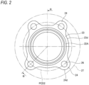
FIG. 2 is a left side view of an outer ring shown inFIG. 1 (a view seen from an outboard side). -
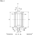
FIG. 3 is a sectional view taken along line III-III inFIG. 2 . -
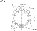
FIG. 4 is a left side view of an outer ring of a modification (a view seen from the outboard side). -
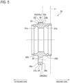
FIG. 5 is a sectional view taken along line V-V inFIG. 4 . -
FIG. 6 is a longitudinal sectional view of a hub unit bearing in the related art. - Hereinafter, embodiments of a hub unit bearing according to the present invention will be described in detail with reference to the drawings.
- In the present specification and claims, the term "outboard side" in relation to an axial direction refers to a left side in
FIG. 1 , which is an outer side in a width direction of a vehicle body when assembled to an automobile, and conversely, a right side inFIG. 1 , which is a center side in the width direction of the vehicle body, is referred to as the "inboard side" in the axial direction. - As shown in
FIG. 1 , a hub unit bearing 10 according to the present embodiment is for a driven wheel, and includes anouter ring 20, ahub 30, a plurality ofrolling elements 40, aseal ring 50, and acap 60. - The
outer ring 20 includes acylindrical portion 22 having a double rowouter ring raceways peripheral flange 23 formed over an entire outer periphery at an axially middle portion of thecylindrical portion 22, and four vehiclebody mounting flanges 24 extending radially outward from positions spaced apart from each other in a circumferential direction of the entireperipheral flange 23. The number of vehiclebody mounting flanges 24 is not limited to four, and may be, for example, three. - The vehicle
body mounting flanges 24 are each formed with aninsertion hole 26 through which aknuckle bolt 25 is inserted. During use, theouter ring 20 does not rotate while supported by aknuckle 11 by coupling and fixing the vehiclebody mounting flange 24 to theknuckle 11 of a suspension device through theknuckle bolt 25. - The
hub 30 is formed by coupling ahub wheel 31 and aninner ring 32, and is disposed coaxially (concentrically) with theouter ring 20 on an inner diameter side of theouter ring 20. - The
hub wheel 31 is provided with awheel mounting flange 33 having a circular ring shape and extending radially outward at a portion located further outboard (on the left side inFIG. 1 ) than an end portion of theouter ring 20 on the outboard side and for supporting and fixing a braking rotary member such as a wheel (driven wheel) and a disc rotor. - A stud bolt (not shown) is serrated and fitted into each of
insertion holes 34 provided in thewheel mounting flange 33 to fix the braking rotary member (not shown) such as the wheel (driven wheel) and the disc rotor. Furthermore, thewheel mounting flange 33 is provided with awork hole 38 at a position corresponding to theinsertion hole 26 of the vehiclebody mounting flange 24, into which a fastening tool (for example, a socket) for fastening theknuckle bolt 25 can be inserted. - Additionally, an inner ring raceway 3 5a on the outboard side is provided on the outer peripheral surface of the
hub wheel 31 in a portion opposing theouter ring raceway 21a on the outboard side provided on the inner peripheral surface of theouter ring 20. A smalldiameter step portion 36 is provided on the outer peripheral surface of thehub wheel 31 at an inboard end portion opposite theouter ring raceway 21b on the inboard side provided on the inner peripheral surface of theouter ring 20. - An
inner ring raceway 35b on the inboard side is provided on the outer peripheral surface of theinner ring 32, and theinner ring 32 is positioned and fixed in the axial direction by acrimp portion 37 formed by crimping the inboard end portion of thehub wheel 31 radially outward in a state in which theinner ring 32 is fitted and fixed to the smalldiameter step portion 36 of thehub wheel 31 by interference fit. - A pitch circle diameter PCD1 of the plurality of
work holes 38 is the same as a pitch circle diameter PCD2 of the plurality ofinsertion holes 26, and a diameter D3 of an inscribed circle of the plurality ofwork holes 38 has a size equal to or larger than a diameter D1 of an outer peripheral surface of an outboardcylindrical portion 22A. Accordingly, the fastening tool for fastening theknuckle bolt 25 can be easily inserted into thework hole 38 without interfering with thecylindrical portion 22, and workability is improved. - A plurality of
rolling elements 40 are rotatably provided between theouter ring raceway 21a and theinner ring raceway 35a on the outboard side and between theouter ring raceway 21b and theinner ring raceway 35b on the inboard side while being held by aholder 41. - In the shown example, balls are used as the
rolling elements 40, but in the case of a rolling bearing unit for supporting wheels of an automobile, which is heavy, tapered rollers may be used instead of the balls. - The
seal ring 50 closes an opening of an outboard end of aninternal space 42 in which the plurality ofrolling elements 40 are provided, which is present between the inner peripheral surface of theouter ring 20 and the outer peripheral surface of thehub 30, in a state in which theseal ring 50 is supported and fixed to an outboard end portion of theouter ring 20. - The
cap 60 is formed in a bottomed cylindrical shape and closes an opening at an inboard end of theouter ring 20 in a state assembled to the inboard end portion of theouter ring 20. - The
encoder 12 is fitted and fixed to the inboard end portion of theinner ring 32 of thehub 30, and a sensor unit (not shown) is assembled to aholding portion 61 of thecap 60. A detection portion of the sensor unit is brought close to and opposite a detection target surface of theencoder 12, thereby making it possible to measure a rotation speed and the like of thehub 30. Since a structure of the sensor unit is not related to the gist of the present invention, detailed descriptions thereof will be omitted. - With reference to
FIGS. 2 and3 , thecylindrical portion 22 of theouter ring 20 includes the outboardcylindrical portion 22A formed on the outboard side of the vehiclebody mounting flange 24 and an inboardcylindrical portion 22B formed on the inboard side of the vehiclebody mounting flange 24. - The diameter D1 of the outer peripheral surface of the outboard
cylindrical portion 22A is formed to be smaller than a diameter D2 of an outer peripheral surface of the inboardcylindrical portion 22B. Furthermore, a radius of curvature of acorner R portion 28a, which has an arc-shaped sectional shape where anoutboard side surface 24a of the vehiclebody mounting flange 24 and the outer peripheral surface of the outboardcylindrical portion 22A intersect, is reduced, thereby increasing an area of theoutboard side surface 24a of the vehiclebody mounting flange 24. - Accordingly, a seating surface on which a
head portion 25a of theknuckle bolt 25 for coupling and fixing theouter ring 20 to theknuckle 11 can be seated can be sufficiently secured on theoutboard side surface 24a of the vehicle body mounting flange 24 (seeFIG. 1 ). Further, when the fastening tool, for example, the socket is set to fasten theknuckle bolt 25, the fastening tool can be prevented from interfering with the outer peripheral surface of the outboardcylindrical portion 22A. - Since the
outer ring 20 formed in this manner has strength that can withstand a load from the wheel, theouter ring 20 is molded by forging as in Patent Literature 2. In particular, in a molding process of theouter ring 20, semi-closed forging for forming the entireperipheral flange 23 and the vehiclebody mounting flange 24 is performed on a billet after an upsetting process, and in the present embodiment, aflash 27, which is an extra material indicated by a phantom line inFIGS. 2 and3 , is formed on the outboard side of the outerperipheral surfaces peripheral flange 23 and the vehiclebody mounting flange 24. Since theflash 27 is removed by a trimming process, aflash mark 27a is formed on the outboard side of the outerperipheral surfaces peripheral flange 23 and the vehiclebody mounting flange 24 in theouter ring 20. - That is, by forming the
flash 27 on the outboard side of the outerperipheral surfaces peripheral flange 23 and the vehiclebody mounting flange 24, a fluidity of a material on the outboard side during forging is improved, and the radius of curvature of thecorner R portion 28a where theoutboard side surface 24a of the vehiclebody mounting flange 24 and the outer peripheral surface of the outboardcylindrical portion 22A intersect is reduced, thereby increasing the area of theoutboard side surface 24a of the vehiclebody mounting flange 24. - Accordingly, it is possible to secure a large area of the
outboard side surface 24a of the vehiclebody mounting flange 24 without cutting theoutboard side surface 24a of the vehiclebody mounting flange 24 or the outer peripheral surface of the outboardcylindrical portion 22A, in other words, without reducing the strength of the vehiclebody mounting flange 24 by cutting a grain flow line on the outboard side. - Since a fluidity of the outboard side is increased, a fluidity of the inboard side is slightly reduced, and a radius of curvature of a
corner R portion 28b where aninboard side surface 24b of the vehiclebody mounting flange 24 and an outer peripheral surface of the inboardcylindrical portion 22B intersect may be increased. - However, even in a case where the
corner R portion 28b is cut to reduce the radius of curvature, and the grain flow line is cut at thecorner R portion 28b, the outer peripheral surface of the inboardcylindrical portion 22B is fitted to theknuckle 11, and thus, there is no problem of strength reduction. Since the diameter D2 of the outer peripheral surface of the inboardcylindrical portion 22B is larger than the diameter D1 of the outer peripheral surface of the outboardcylindrical portion 22A, that is a thickness of the inboardcylindrical portion 22B is greater than a thickness of the outboardcylindrical portion 22A, the strength of the inboardcylindrical portion 22B is ensured. - As described above, according to the hub unit bearing 10 of the present embodiment, a large area of the
outboard side surface 24a of the vehiclebody mounting flange 24 can be ensured while maintaining the strength achieved by forging, without performing cutting on the outboardcylindrical portion 22A of theouter ring 20. - Next, an outer ring of a hub unit bearing according to a modification of the present embodiment will be described with reference to
FIGS. 4 and5 . - As shown in
FIGS. 4 and5 , as described above, theouter ring 20 of the present modification is also molded by a semi-closed forging die (not shown, and see, for example,FIG. 3 ofJP2015-107459A peripheral flange 23 and the vehiclebody mounting flange 24. Therefore, the outerperipheral surfaces peripheral flange 23 and the vehiclebody mounting flange 24 areinclined surfaces - When the
outer ring 20 whose outerperipheral surfaces inclined surfaces knuckle 11 by the vehiclebody mounting flange 24, an arc-shaped recess 39 (FIG. 5 ) having a V-shaped cross section in the axial direction is formed in which an arc-shaped contact edge portion between anedge portion 23e on the inboard side of the entire peripheral flange 23 (FIG. 4 ) located on an upper side and theknuckle 11 serves as a bottom portion. - In particular, when the vehicle
body mounting flange 24 is four, both sides in the circumferential direction of the recess 39 are closed by the two vehiclebody mounting flanges 24, and thus water adhering to theinclined surface 23c (outerperipheral surface 23d), which is an upper surface of the entireperipheral flange 23, flows to the inboard side through theinclined surface 23c and remains in the recess 39 to form a puddle. The water accumulated in the recess 39 may cause rust in the hub unit bearing 10 and theknuckle 11. - For this reason, in the
outer ring 20 of the present modification,drain grooves 29 that gradually decrease in diameter from theedge portion 23e on the inboard side of the entireperipheral flange 23 positioned on the upper side or a position having a smaller diameter than theedge portion 23e toward the outboard side are provided on both sides in the circumferential direction of theinclined surface 23c. Thedrain groove 29 is preferably provided at a position facing each other on the inner side in the circumferential direction of the two vehiclebody mounting flanges 24 adjacent to each other in the circumferential direction on the upper side, that is, at the lowest position of the recess 39 serving as a puddle. Accordingly, most of water flowing toward the inboard side can be discharged from theinclined surface 23c (outerperipheral surface 23d), and the cause of rust in the hub unit bearing 10 and theknuckle 11 can be eliminated. Thedrain groove 29 may have any shape and may be formed by cutting, but is preferably formed by additional forging. - Other parts other than those described above are the same as those of the hub unit bearing of the first embodiment, and therefore descriptions thereof will be omitted.
- The present invention is not limited to the above-described embodiments and modifications, and modifications, improvements, and the like can be appropriately made.
- For example, in the above embodiment, the vehicle body mounting flange extends radially outward from the entire peripheral flange, but the present invention is not limited thereto, and the vehicle body mounting flange may extend radially outward from the periphery of the cylindrical portion.
- Further, the hub of the present invention is not limited to that of the above embodiment, and may be formed by a hub shaft and a pair of inner rings.
- As described above, the following matters are disclosed in the present specification.
- (1) A hub unit bearing including:
- an outer ring including a cylindrical portion having an outer ring raceway on an inner peripheral surface and a vehicle body mounting flange extending radially outward from a periphery of the cylindrical portion and having a plurality of insertion holes through which knuckle bolts are inserted;
- a hub having an inner ring raceway at a position facing the outer ring raceway on an outer peripheral surface and a wheel mounting flange extending radially outward from a portion located on an outboard side of the outer ring; and
- a plurality of rolling elements reliably provided between the outer ring raceway and the inner ring raceway, in which
- a flash mark is formed on an outer peripheral surface of the vehicle body mounting flange on the outboard side.
- According to this configuration, a large area of an outboard side surface of the vehicle body mounting flange can be ensured while maintaining strength achieved by forging, without performing cutting on the outboard cylindrical portion of the outer ring.
- (2) The hub unit bearing according to (1), in which
the cylindrical portion of the outer ring is formed such that a diameter of an outer peripheral surface on the outboard side with respect to the vehicle body mounting flange is smaller than a diameter of an outer peripheral surface on an inboard side with respect to the vehicle body mounting flange. - According to this configuration, it is possible not only to ensure a large area of the outboard side surface of the vehicle body mounting flange, but also to increase a thickness of the inboard cylindrical portion.
- (3) The hub unit bearing according to (1) or (2), in which
- the wheel mounting flange includes a plurality of work holes into which a fastening tool for fastening the knuckle bolt is capable of being inserted,
- a pitch circle diameter of the plurality of work holes is the same as a pitch circle diameter of the plurality of insertion holes, and a diameter of an inscribed circle of the plurality of work holes is equal to or larger than a diameter of an outer peripheral surface of the cylindrical portion on the outboard side.
- According to this configuration, the fastening tool for fastening the knuckle bolt can be easily inserted from the work hole of the wheel mounting flange, and workability is improved.
- (4) The hub unit bearing according to any one of (1) to (3), in which
- the outer ring includes a plurality of the vehicle body mounting flanges extending radially outward from a periphery of an entire peripheral flange formed over an entire outer periphery of the cylindrical portion, and
- an outer peripheral surface of the entire peripheral flange provided between the vehicle body mounting flanges adjacent to each other in a circumferential direction on an upper side includes an inclined surface inclined to have a smaller diameter toward the inboard side, and a drain groove having a smaller diameter toward the outboard side from an edge portion of the entire peripheral flange on the inboard side or a position having a smaller diameter than the edge portion.
- According to this configuration, the water flowing to the inboard side from the inclined surface formed on the outer peripheral surface of the entire peripheral flange positioned at the upper side and inclined toward the inboard side can be discharged to the outboard side, and the occurrence of rust in the hub unit bearing and the knuckle can be prevented.
- The present application is based on a
Japanese Patent Application (No. 2022-026689) filed on February 24, 2022 -
- 10 hub unit bearing
- 20 outer ring
- 21a, 21b outer ring raceway
- 22A outboard cylindrical portion (cylindrical portion of outer ring)
- 22B inboard cylindrical portion (cylindrical portion of outer ring)
- 23 entire peripheral flange
- 23c inclined surface
- 23d outer peripheral surface of entire peripheral flange
- 23e edge portion
- 24 vehicle body mounting flange
- 24d outer peripheral surface of vehicle body mounting flange
- 25 knuckle bolt
- 26 insertion hole
- 27 flash
- 27a flash mark
- 29 drain groove
- 30 hub
- 33 wheel mounting flange
- 35a, 35b inner ring raceway
- 38 work hole
- 40 rolling element
- D1 diameter of outboard cylindrical portion
- D2 diameter of inboard cylindrical portion
- D3 diameter of inscribed circle of work hole
- PCD1, PCD2 pitch circle diameter
Claims (4)
- A hub unit bearing comprising:an outer ring including a cylindrical portion having an outer ring raceway on an inner peripheral surface and a vehicle body mounting flange extending radially outward from a periphery of the cylindrical portion and having a plurality of insertion holes through which knuckle bolts are inserted;a hub having an inner ring raceway at a position facing the outer ring raceway on an outer peripheral surface and a wheel mounting flange extending radially outward from a portion located on an outboard side of the outer ring; anda plurality of rolling elements reliably provided between the outer ring raceway and the inner ring raceway, whereina flash mark is formed on an outer peripheral surface of the vehicle body mounting flange on the outboard side.
- The hub unit bearing according to claim 1, wherein
the cylindrical portion of the outer ring is formed such that a diameter of an outer peripheral surface on the outboard side with respect to the vehicle body mounting flange is smaller than a diameter of an outer peripheral surface on an inboard side with respect to the vehicle body mounting flange. - The hub unit bearing according to claim 1 or 2, whereinthe wheel mounting flange includes a plurality of work holes into which a fastening tool for fastening the knuckle bolt is capable of being inserted,a pitch circle diameter of the plurality of work holes is the same as a pitch circle diameter of the plurality of insertion holes, and a diameter of an inscribed circle of the plurality of work holes is equal to or larger than a diameter of an outer peripheral surface of the cylindrical portion on the outboard side.
- The hub unit bearing according to any one of claims 1 to 3, whereinthe outer ring includes a plurality of the vehicle body mounting flanges extending radially outward from a periphery of an entire peripheral flange formed over an entire outer periphery of the cylindrical portion, andan outer peripheral surface of the entire peripheral flange provided between the vehicle body mounting flanges adjacent to each other in a circumferential direction on an upper side includes an inclined surface inclined to have a smaller diameter toward the inboard side, and a drain groove having a smaller diameter toward the outboard side from an edge portion of the entire peripheral flange on the inboard side or a position having a smaller diameter than the edge portion.
Applications Claiming Priority (2)
| Application Number | Priority Date | Filing Date | Title |
|---|---|---|---|
| JP2022026689A JP7800198B2 (en) | 2022-02-24 | 2022-02-24 | Hub unit bearing and method of manufacturing the same |
| PCT/JP2022/035266 WO2023162313A1 (en) | 2022-02-24 | 2022-09-21 | Hub unit bearing |
Publications (2)
| Publication Number | Publication Date |
|---|---|
| EP4484779A1 true EP4484779A1 (en) | 2025-01-01 |
| EP4484779A4 EP4484779A4 (en) | 2025-06-04 |
Family
ID=87765305
Family Applications (1)
| Application Number | Title | Priority Date | Filing Date |
|---|---|---|---|
| EP22928834.5A Pending EP4484779A4 (en) | 2022-02-24 | 2022-09-21 | HUB UNIT BEARING |
Country Status (4)
| Country | Link |
|---|---|
| EP (1) | EP4484779A4 (en) |
| JP (1) | JP7800198B2 (en) |
| CN (1) | CN118742744A (en) |
| WO (1) | WO2023162313A1 (en) |
Family Cites Families (10)
| Publication number | Priority date | Publication date | Assignee | Title |
|---|---|---|---|---|
| JP4936700B2 (en) * | 2005-09-29 | 2012-05-23 | Ntn株式会社 | Wheel bearing device and manufacturing method thereof |
| JP2008064261A (en) * | 2006-09-11 | 2008-03-21 | Nsk Ltd | Manufacturing method of outer ring of rolling bearing unit for wheel support |
| JP5146070B2 (en) * | 2008-04-17 | 2013-02-20 | 日本精工株式会社 | Plastic working method and plastic working apparatus for metal member |
| JP5966726B2 (en) * | 2012-07-26 | 2016-08-10 | 日本精工株式会社 | Method for manufacturing bearing ring member |
| JP6191423B2 (en) | 2013-12-03 | 2017-09-06 | 日本精工株式会社 | Manufacturing method of outer ring for rolling bearing unit and outer ring for rolling bearing unit |
| JP2015107459A (en) | 2013-12-04 | 2015-06-11 | トヨタ紡織株式会社 | Mandrel for oil filter |
| JP2016148380A (en) * | 2015-02-12 | 2016-08-18 | 株式会社ジェイテクト | Manufacturing method of bearing ring and manufacturing method of bearing |
| JP6788453B2 (en) * | 2016-09-20 | 2020-11-25 | Ntn株式会社 | Bearing device for wheels |
| JP2020085205A (en) | 2018-11-30 | 2020-06-04 | 株式会社ジェイテクト | Wheel bearing device |
| JP6977749B2 (en) * | 2019-08-19 | 2021-12-08 | 日本精工株式会社 | Hub unit bearing and its manufacturing method, rocking caulking device, vehicle and its manufacturing method |
-
2022
- 2022-02-24 JP JP2022026689A patent/JP7800198B2/en active Active
- 2022-09-21 CN CN202280092502.4A patent/CN118742744A/en active Pending
- 2022-09-21 WO PCT/JP2022/035266 patent/WO2023162313A1/en not_active Ceased
- 2022-09-21 EP EP22928834.5A patent/EP4484779A4/en active Pending
Also Published As
| Publication number | Publication date |
|---|---|
| WO2023162313A1 (en) | 2023-08-31 |
| CN118742744A (en) | 2024-10-01 |
| JP2023122912A (en) | 2023-09-05 |
| EP4484779A4 (en) | 2025-06-04 |
| JP7800198B2 (en) | 2026-01-16 |
Similar Documents
| Publication | Publication Date | Title |
|---|---|---|
| US7942585B2 (en) | Wheel bearing apparatus for a vehicle | |
| JP6449689B2 (en) | Wheel bearing device | |
| CN102602245B (en) | Bearing unit for wheel | |
| US11273670B2 (en) | Hub unit bearing | |
| EP1939471A1 (en) | Bearing device for wheel | |
| EP3444491B2 (en) | Hub unit bearing | |
| US20150191044A1 (en) | Bearing module | |
| JP4936712B2 (en) | Wheel bearing device | |
| EP4484779A1 (en) | Hub unit bearing | |
| US8142081B2 (en) | Wheel support bearing assembly | |
| JP2007290681A (en) | Drive wheel support hub unit and method of manufacturing the same | |
| JP6366233B2 (en) | Wheel bearing device | |
| JP2008173995A (en) | Bearing device for wheel | |
| EP2572899A1 (en) | Rolling bearing device for wheel | |
| US20090154856A1 (en) | Wheel Support Bearing Assembly and Method of Manufacturing the Same | |
| JP2017065296A (en) | Bearing device for wheel | |
| EP2587078A1 (en) | Wheel bearing device | |
| JP4042528B2 (en) | Rolling bearing device | |
| EP2106928B1 (en) | Wheel rolling bearing assembly and manufacturing method thereof | |
| JP7754738B2 (en) | Wheel bearing device | |
| JP2006007910A (en) | Bearing device for wheel | |
| JP5236097B2 (en) | Wheel bearing device | |
| JP4993342B2 (en) | Wheel bearing device | |
| JP4969899B2 (en) | Wheel bearing device | |
| JP4993341B2 (en) | Wheel bearing device |
Legal Events
| Date | Code | Title | Description |
|---|---|---|---|
| STAA | Information on the status of an ep patent application or granted ep patent |
Free format text: STATUS: THE INTERNATIONAL PUBLICATION HAS BEEN MADE |
|
| PUAI | Public reference made under article 153(3) epc to a published international application that has entered the european phase |
Free format text: ORIGINAL CODE: 0009012 |
|
| STAA | Information on the status of an ep patent application or granted ep patent |
Free format text: STATUS: REQUEST FOR EXAMINATION WAS MADE |
|
| 17P | Request for examination filed |
Effective date: 20240822 |
|
| AK | Designated contracting states |
Kind code of ref document: A1 Designated state(s): AL AT BE BG CH CY CZ DE DK EE ES FI FR GB GR HR HU IE IS IT LI LT LU LV MC MK MT NL NO PL PT RO RS SE SI SK SM TR |
|
| DAV | Request for validation of the european patent (deleted) | ||
| DAX | Request for extension of the european patent (deleted) | ||
| A4 | Supplementary search report drawn up and despatched |
Effective date: 20250506 |
|
| RIC1 | Information provided on ipc code assigned before grant |
Ipc: B60B 27/00 20060101ALI20250429BHEP Ipc: F16C 33/64 20060101ALI20250429BHEP Ipc: F16C 33/58 20060101ALI20250429BHEP Ipc: F16C 19/18 20060101AFI20250429BHEP |
|
| GRAP | Despatch of communication of intention to grant a patent |
Free format text: ORIGINAL CODE: EPIDOSNIGR1 |
|
| STAA | Information on the status of an ep patent application or granted ep patent |
Free format text: STATUS: GRANT OF PATENT IS INTENDED |