EP4484778A1 - Bearing device - Google Patents
Bearing device Download PDFInfo
- Publication number
- EP4484778A1 EP4484778A1 EP23774688.8A EP23774688A EP4484778A1 EP 4484778 A1 EP4484778 A1 EP 4484778A1 EP 23774688 A EP23774688 A EP 23774688A EP 4484778 A1 EP4484778 A1 EP 4484778A1
- Authority
- EP
- European Patent Office
- Prior art keywords
- bearing
- ring
- circuit board
- magnetic
- stator
- Prior art date
- Legal status (The legal status is an assumption and is not a legal conclusion. Google has not performed a legal analysis and makes no representation as to the accuracy of the status listed.)
- Granted
Links
Images





Classifications
-
- F—MECHANICAL ENGINEERING; LIGHTING; HEATING; WEAPONS; BLASTING
- F16—ENGINEERING ELEMENTS AND UNITS; GENERAL MEASURES FOR PRODUCING AND MAINTAINING EFFECTIVE FUNCTIONING OF MACHINES OR INSTALLATIONS; THERMAL INSULATION IN GENERAL
- F16C—SHAFTS; FLEXIBLE SHAFTS; ELEMENTS OR CRANKSHAFT MECHANISMS; ROTARY BODIES OTHER THAN GEARING ELEMENTS; BEARINGS
- F16C41/00—Other accessories, e.g. devices integrated in the bearing not relating to the bearing function as such
- F16C41/008—Identification means, e.g. markings, RFID-tags; Data transfer means
-
- F—MECHANICAL ENGINEERING; LIGHTING; HEATING; WEAPONS; BLASTING
- F16—ENGINEERING ELEMENTS AND UNITS; GENERAL MEASURES FOR PRODUCING AND MAINTAINING EFFECTIVE FUNCTIONING OF MACHINES OR INSTALLATIONS; THERMAL INSULATION IN GENERAL
- F16C—SHAFTS; FLEXIBLE SHAFTS; ELEMENTS OR CRANKSHAFT MECHANISMS; ROTARY BODIES OTHER THAN GEARING ELEMENTS; BEARINGS
- F16C32/00—Bearings not otherwise provided for
- F16C32/04—Bearings not otherwise provided for using magnetic or electric supporting means
- F16C32/0406—Magnetic bearings
- F16C32/044—Active magnetic bearings
- F16C32/0474—Active magnetic bearings for rotary movement
- F16C32/0476—Active magnetic bearings for rotary movement with active support of one degree of freedom, e.g. axial magnetic bearings
-
- F—MECHANICAL ENGINEERING; LIGHTING; HEATING; WEAPONS; BLASTING
- F16—ENGINEERING ELEMENTS AND UNITS; GENERAL MEASURES FOR PRODUCING AND MAINTAINING EFFECTIVE FUNCTIONING OF MACHINES OR INSTALLATIONS; THERMAL INSULATION IN GENERAL
- F16C—SHAFTS; FLEXIBLE SHAFTS; ELEMENTS OR CRANKSHAFT MECHANISMS; ROTARY BODIES OTHER THAN GEARING ELEMENTS; BEARINGS
- F16C19/00—Bearings with rolling contact, for exclusively rotary movement
- F16C19/02—Bearings with rolling contact, for exclusively rotary movement with bearing balls essentially of the same size in one or more circular rows
- F16C19/04—Bearings with rolling contact, for exclusively rotary movement with bearing balls essentially of the same size in one or more circular rows for radial load mainly
- F16C19/06—Bearings with rolling contact, for exclusively rotary movement with bearing balls essentially of the same size in one or more circular rows for radial load mainly with a single row or balls
-
- F—MECHANICAL ENGINEERING; LIGHTING; HEATING; WEAPONS; BLASTING
- F16—ENGINEERING ELEMENTS AND UNITS; GENERAL MEASURES FOR PRODUCING AND MAINTAINING EFFECTIVE FUNCTIONING OF MACHINES OR INSTALLATIONS; THERMAL INSULATION IN GENERAL
- F16C—SHAFTS; FLEXIBLE SHAFTS; ELEMENTS OR CRANKSHAFT MECHANISMS; ROTARY BODIES OTHER THAN GEARING ELEMENTS; BEARINGS
- F16C41/00—Other accessories, e.g. devices integrated in the bearing not relating to the bearing function as such
-
- F—MECHANICAL ENGINEERING; LIGHTING; HEATING; WEAPONS; BLASTING
- F16—ENGINEERING ELEMENTS AND UNITS; GENERAL MEASURES FOR PRODUCING AND MAINTAINING EFFECTIVE FUNCTIONING OF MACHINES OR INSTALLATIONS; THERMAL INSULATION IN GENERAL
- F16C—SHAFTS; FLEXIBLE SHAFTS; ELEMENTS OR CRANKSHAFT MECHANISMS; ROTARY BODIES OTHER THAN GEARING ELEMENTS; BEARINGS
- F16C41/00—Other accessories, e.g. devices integrated in the bearing not relating to the bearing function as such
- F16C41/004—Electro-dynamic machines, e.g. motors, generators, actuators
-
- F—MECHANICAL ENGINEERING; LIGHTING; HEATING; WEAPONS; BLASTING
- F16—ENGINEERING ELEMENTS AND UNITS; GENERAL MEASURES FOR PRODUCING AND MAINTAINING EFFECTIVE FUNCTIONING OF MACHINES OR INSTALLATIONS; THERMAL INSULATION IN GENERAL
- F16C—SHAFTS; FLEXIBLE SHAFTS; ELEMENTS OR CRANKSHAFT MECHANISMS; ROTARY BODIES OTHER THAN GEARING ELEMENTS; BEARINGS
- F16C41/00—Other accessories, e.g. devices integrated in the bearing not relating to the bearing function as such
- F16C41/007—Encoders, e.g. parts with a plurality of alternating magnetic poles
-
- H—ELECTRICITY
- H02—GENERATION; CONVERSION OR DISTRIBUTION OF ELECTRIC POWER
- H02K—DYNAMO-ELECTRIC MACHINES
- H02K7/00—Arrangements for handling mechanical energy structurally associated with dynamo-electric machines, e.g. structural association with mechanical driving motors or auxiliary dynamo-electric machines
- H02K7/08—Structural association with bearings
- H02K7/09—Structural association with bearings with magnetic bearings
-
- F—MECHANICAL ENGINEERING; LIGHTING; HEATING; WEAPONS; BLASTING
- F16—ENGINEERING ELEMENTS AND UNITS; GENERAL MEASURES FOR PRODUCING AND MAINTAINING EFFECTIVE FUNCTIONING OF MACHINES OR INSTALLATIONS; THERMAL INSULATION IN GENERAL
- F16C—SHAFTS; FLEXIBLE SHAFTS; ELEMENTS OR CRANKSHAFT MECHANISMS; ROTARY BODIES OTHER THAN GEARING ELEMENTS; BEARINGS
- F16C2233/00—Monitoring condition, e.g. temperature, load, vibration
Definitions
- the present disclosure relates to a bearing device.
- bearing device formed of a combination of a bearing and a generator and used as a power supply for a sensor, wireless communication, and the like.
- Japanese Patent Laying-Open No. 2017-72170 discloses a bearing device equipped with a wireless sensor and configured to wirelessly transmit information from a sensor.
- the bearing device disclosed in PTL 1 has a structure in which a multipole ring magnet is fixed to one end of a cage holding a rolling element, and a coil is disposed on a seal side facing the multipole ring magnet.
- electric power is generated by relative rotation of the multipole ring magnet and the coil that are disposed in the axial direction.
- the cage significantly rattles in the axial direction of the bearing.
- the gap between the multipole ring magnet and the coil in the axial direction tends to vary due to such rattling of the cage caused by its use.
- the gap becomes larger the amount of power generation decreases, which exerts an influence upon the driving of electronic components such as a sensor.
- the multipole ring magnet comes into contact with electronic components such as a sensor.
- the present disclosure has been made to solve the above-described problems, an object thereof is to provide a bearing device that is reduced in dimensions and still capable of functioning normally.
- a bearing device of the present disclosure includes: a standard bearing as a bearing that includes an outer ring, an inner ring, and a rolling element, the bearing having main dimensions defined under specific standards.
- the bearing device includes: a magnetic ring fixed to one of the outer ring or the inner ring; a stator disposed to face the magnetic ring in a radial direction of the standard bearing and fixed to the other of the outer ring or the inner ring; and a circuit board.
- the magnetic ring and the stator constitute a generator that generates alternating-current (AC) power.
- the circuit board includes: at least one sensor that detects a state of the standard bearing; a wireless communication circuit that wirelessly transmits an output from the at least one sensor to outside; and a power supply circuit that converts AC power generated by the generator into direct-current (DC) power usable in the at least one sensor and the wireless communication circuit.
- the magnetic ring, the stator, and the circuit board are disposed inside an annular space formed by a recess in an end portion of the outer ring and a recess in an end portion of the inner ring.
- the magnetic ring, the stator, and the circuit board are disposed inside the annular space so as not to overlap with each other in the axial direction of the bearing.
- each component can be disposed inside the annular space, so that the bearing can be reduced in dimensions.
- the magnetic ring is fixed to the inner ring
- the stator is fixed to the outer ring at the position facing the magnetic ring. The displacement of the inner ring and the outer ring in the axial direction of the bearing is relatively small, and the magnetic ring and the stator constitute the generator, with the result that the bearing device is reduced in dimensions and still capable of functioning normally.
- Fig. 1 is a perspective view showing the entirety of a bearing device 1 according to the first embodiment.
- Bearing device 1 includes a bearing 2, a sensor unit 6, and a magnetic ring 7.
- Bearing 2 includes an outer ring 3 and an inner ring 4.
- outer ring 3 serves as a stationary ring
- inner ring 4 serves as a rotation ring.
- a deep groove ball bearing will be described as an example of bearing 2, the type of bearing 2 is not limited to such a deep groove ball bearing.
- bearing 2 is a standard bearing as a bearing whose main dimensions (an inside diameter, an outside diameter, a width, and the like) are defined in specific standards.
- the standard bearing is a bearing having dimensions defined, for example, in ISO standards or JIS standards.
- Bearing 2 is a radial bearing and has main dimensions defined in ISO 15 or JIS B 1512-1. In the following, bearing 2 is also referred to as a standard bearing 2.
- Sensor unit 6 includes a stator 5 and a lid 14.
- the structure of stator 5 will be described later in detail.
- Lid 14 is a non-metal resin member and protects the inside of sensor unit 6.
- Magnetic ring 7 is a magnetic member in which N poles and S poles are alternately magnetized in the circumferential direction.
- Stator 5 is fixed to outer ring 3, and magnetic ring 7 is fixed to inner ring 4.
- Stator 5 and magnetic ring 7 constitute a generator G.
- Generator G is a claw pole-type generator but may be a generator having another structure.
- Fig. 1 shows a one-dot chain line indicating a rotation axis O of bearing 2.
- Fig. 2 is a cross-sectional view along a plane including rotation axis O of bearing 2.
- Bearing 2 includes outer ring 3, inner ring 4, a rolling element 8, a cage 9, and a seal 10.
- Bearing 2 should only be selected from those having a size of the model number of the standard bearing having a distance W between an end face 11 of bearing 2 and rolling element 8 such that sensor unit 6 and magnetic ring 7 can be accommodated within distance W.
- End face 11 is also an end face of outer ring 3.
- An inner circumferential surface at one end of outer ring 3 has a first cutout portion 3a provided as a stepped portion and formed as a recess in an end portion of outer ring 3.
- An outer circumferential surface at one end of inner ring 4 has a second cutout portion 4a provided as a stepped portion and formed as a recess in an end portion of inner ring 4 so as to face first cutout portion 3a.
- an annular space by an annular recess 50 that is cut out toward rolling element 8 is formed by first cutout portion 3a and second cutout portion 4a so as to extend from outer ring 3 to inner ring 4.
- Sensor unit 6 includes a cage member 12, a circuit board 13, stator 5, and lid 14.
- Cage member 12 is a magnetic material having a partition wall 12a that partitions cage member 12 into a first region 12b and a second region 12c in a radial direction (also referred to as radially) of bearing 2.
- Circuit board 13 is fixed to an inner bottom surface 12d of first region 12b, and stator 5 is disposed in second region 12c.
- Lid 14 protects circuit board 13 fixed to inner bottom surface 12d.
- a resin sealing material may be used to seal circuit board 13.
- cage member 12 on the first region 12b side is fitted in and fixed to first cutout portion 3a formed in outer ring 3.
- Cage member 12 is press-fitted or bonded so as not to protrude from end face 11 of outer ring 3.
- Cage member 12 may be fixed by both press-fitting and bonding, or may be fixed by other methods.
- Stator 5 includes two magnetic members 21 and 22, a bobbin 23, and a coil 24. A portion of cage member 12 that includes second region 12c is used as magnetic member 21 of stator 5.
- Magnetic ring 7 includes a core metal 7a and a multipole magnet 7b.
- Multipole magnet 7b is formed, for example, by kneading magnetic powder with rubber to obtain a magnetic material, which is then vulcanized and bonded to core metal 7a, to which N poles and S poles are alternately magnetized in the circumferential direction of bearing 2.
- Core metal 7a of magnetic ring 7 has a flange portion 7c in order to increase rigidity.
- Magnetic ring 7 is fixed to an outside surface 4b of inner ring 4 by press-fitting or the like.
- Flange portion 7c is accommodated in second cutout portion 4a provided in inner ring 4.
- Magnetic ring 7 is disposed so as not to protrude from end face 20 of inner ring 4.
- annular recess 50 magnetic ring 7, stator 5, and circuit board 13 are disposed so as not to overlap with each other in the axial direction of bearing 2. Thereby, each component can be disposed inside this annular recess 50, so that bearing 2 can be reduced in dimensions.
- bearing device 1 for example, magnetic ring 7 is fixed to inner ring 4, and stator 5 is fixed to outer ring 3 at a position facing magnetic ring 7.
- the displacement of inner ring 4 and outer ring 3 in the axial direction of bearing 2 is relatively small as compared with cage 9, and thus, the stable amount of power generation can be ensured by generator G, and the bearing device is reduced in dimensions and still capable of functioning normally.
- Fig. 3 is a diagram for illustrating cage 9.
- Cage 9 is provided with recesses 93 formed at a prescribed pitch in the circumferential direction of an end face 91 in the axial direction of the annular cage body.
- a pair of claw portions 94 and 94 are formed to protrude from opening ends of recess 93 that face each other in the circumferential direction of recess 93.
- Recess 93 and the pair of claw portions 94 and 94 form a pocket 95 in which rolling element 8 shown in Fig. 2 is accommodated.
- cage 9 is shaped to be open on the end face 91 side as one side and to be connected on the side of an end face 92 as the other side.
- Cage 9, which is a resin-made member, is disposed on the open side such that sensor unit 6 and magnetic ring 7 do not protrude from end faces 11 and 20.
- Fig. 4 is a diagram of bearing device 1 viewed from the sensor unit 6 side. Fig. 4 does not show a part of lid 14 such that the inside of sensor unit 6 can be seen.
- One or more sensors for monitoring the state of bearing 2 are mounted on circuit board 13.
- an acceleration sensor 15 and a temperature sensor 16 are mounted on circuit board 13.
- temperature sensor 16 may be inserted through a hole (not shown) provided in inner bottom surface 12d of cage member 12 and then mounted on the rear surface of circuit board 13 so as to be located close to (or to be in contact with) the end face of first cutout portion 3a of outer ring 3. Thereby, temperature sensor 16 is located close to outer ring 3 and thereby can accurately measure the temperature of bearing 2.
- a power supply circuit 17 and a wireless communication circuit 18 are further mounted.
- Power supply circuit 17 rectifies AC power generated by generator G and converts the rectified AC power into DC power.
- the DC power converted by power supply circuit 17 is used in acceleration sensor 15, temperature sensor 16, and wireless communication circuit 18.
- a terminal 25 is disposed on circuit board 13.
- Wireless communication circuit 18 includes an antenna portion 18a. Wireless communication circuit 18 wirelessly transmits the outputs from acceleration sensor 15 and temperature sensor 16, which monitor the state of bearing 2, to the outside through antenna portion 18a.
- Circuit board 13 is fixed to cage member 12 with a plurality of screws 19. Circuit board 13 may be bonded and fixed to cage member 12. Circuit board 13 on which wireless communication circuit 18 is mounted is disposed to face lid 14 made of resin. Thereby, wireless communication circuit 18 has a structure not hermetically sealed with a conductive material such as metal. This allows wireless communication through antenna portion 18a in wireless communication circuit 18.
- Fig. 5 is an exploded perspective view of sensor unit 6.
- Fig. 6 is a perspective view of sensor unit 6 after assembly.
- Sensor unit 6 includes cage member 12, circuit board 13, and stator 5.
- Circuit board 13 is fixed to inner bottom surface 12d of first region 12b of cage member 12.
- Stator 5 is disposed in second region 12c of cage member 12.
- Stator 5 includes two magnetic members 21 and 22, bobbin 23, and coil 24.
- a part of cage member 12 that includes partition wall 12a of second region 12c is used as magnetic member 21 of stator 5.
- Each of magnetic members 21 and 22 has a U-shaped cross section.
- a plurality of claw portions 21a are formed on an inner circumferential portion of magnetic member 21.
- a plurality of claw portions 22a are formed on an inner circumferential portion of magnetic member 22.
- Coil 24 around which a magnet wire is wound a plurality of times is disposed in a groove provided in bobbin 23 in its circumferential direction. Bobbin 23 may not be provided.
- stator 5 The following describes an assembly method for stator 5. First, in the state in which bobbin 23 wound with coil 24 is inserted into magnetic member 22, the plurality of claw portions 21a of magnetic member 21 and the plurality of claw portions 22a of magnetic member 22 are assembled to be alternately arranged with a gap interposed therebetween in the circumferential direction. Then, an outer circumferential surface 22b of magnetic member 22 is fixed to be fitted in the inner circumferential surface of partition wall 12a of magnetic member 21.
- the plurality of claw portions 21a of magnetic member 21 and the plurality of claw portions 22a of magnetic member 22 are disposed to respectively face each other while ensuring a gap between each of claw portions 21a, 22a and multipole magnet 7b of magnetic ring 7 shown in Fig. 2 .
- Claw pole-type generator G is formed by magnetic ring 7, and the plurality of claw portions 21a of magnetic member 21 and the plurality of claw portions 22a of magnetic member 22 in stator 5.
- the total number of the plurality of claw portions 21a and 22a is equal to the number of poles (the total number of the N and S poles) in multipole magnet 7b.
- the magnetic flux emitted from the N pole of multipole magnet 7b flows, for example, from the plurality of claw portions 21a (or the plurality of claw portions 22a) each serving as a magnetic pole into magnetic member 21 (or magnetic member 22), flows around coil 24, and passes through the plurality of claw portions 22a (or the plurality of claw portions 21a) adjacent thereto, and then flows back to the S pole of multipole magnet 7b.
- the positions of the N pole and the S pole of multipole magnet 7b are replaced with each other by the rotation of inner ring 4, the direction of the magnetic flux is reversed.
- the alternating magnetic field generated in this way generates AC power at both ends of coil 24.
- Each of the ends (not shown) of the winding start and the winding end of coil 24 pulled out of stator 5 is connected to terminal 25 provided on circuit board 13.
- the AC power output from generator G by the rotation of inner ring 4 is converted into DC power by power supply circuit 17.
- Sensor unit 6 of bearing device 1 is divided by partition wall 12a into first region 12b and second region 12c in the radial direction of cage member 12.
- Circuit board 13 is disposed in first region 12b, and stator 5 in claw pole-type generator G is disposed in second region 12c.
- Magnetic ring 7 is disposed on the side of the inside diameter to face stator 5.
- bearing device 1 is structured such that circuit board 13, stator 5, and magnetic ring 7 are sequentially disposed so as not to overlap with each other in the axial direction of bearing 2. Further, bearing device 1 is shaped such that sensor unit 6 does not protrude from end face 11 of bearing 2, and also shaped such that magnetic ring 7 does not protrude from end face 20 of inner ring 4. Thereby, in bearing device 1, sensor unit 6 can be formed to be thin in the axial direction.
- stator 5 and magnetic ring 7 are disposed in the radial direction to constitute claw pole-type generator G.
- stator 5 and magnetic ring 7 are fixed to a component with less rattling caused by the use of bearing device 1, and thereby, the stable amount of power generation can be ensured by generator G.
- cage member 12 is divided by partition wall 12a into two regions including first region 12b and second region 12c.
- the portion of cage member 12 that includes first region 12b is used for holding circuit board 13, and the portion of cage member 12 that includes second region 12c is used also as magnetic member 21.
- bearing device 1 the number of components can be reduced, and stator 5 can be firmly fixed to cage member 12.
- a sensor unit 6A different in structure from sensor unit 6 in the first embodiment will be described.
- Fig. 7 is a cross-sectional view showing only sensor unit 6A and magnetic ring 7 in the second embodiment.
- Fig. 8 is an exploded perspective view of sensor unit 6A according to the second embodiment.
- Fig. 9 is a perspective view of sensor unit 6A according to the second embodiment after assembly. In the following, the description of the same configurations as those of sensor unit 6 in the first embodiment will not be repeated.
- Sensor unit 6A includes a cage member 12A, circuit board 13, a stator 5A, and lid 14.
- Cage member 12A does not have partition wall 12a in the first embodiment.
- Cage member 12A has an annular shape and has a U-shaped cross section including an outer circumferential portion 12Ab, an inner circumferential portion 12Aa, and a bottom portion 12Ad connecting outer circumferential portion 12Ab and inner circumferential portion 12Aa.
- Stator 5A is fixed to the side surface of inner circumferential portion 12Aa by press-fitting. Stator 5A may be fixed by bonding, or may be fixed by both press-fitting and bonding.
- Circuit board 13 is fixed to bottom portion 12Ad of cage member 12A.
- Stator 5A includes a magnetic member 26, bobbin 23, and coil 24.
- Magnetic member 26 includes a magnetic member 26-1 and a magnetic member 26-2.
- Each of magnetic members 26-1 and 26-2 has a U-shaped cross section.
- Magnetic member 26-1 has an inner circumferential portion provided with a plurality of claw portions 26a.
- Magnetic member 26-2 has an inner circumferential portion provided with a plurality of claw portions 26b. The plurality of claw portions 26a and the plurality of claw portions 26b are alternately arranged with a gap interposed therebetween in the circumferential direction.
- Magnetic members 26-1 and 26-2 have outer circumferential portions provided with a plurality of recesses 26c and a plurality of protrusions 26d, respectively. By engagement between recesses 26c and protrusions 26d, the plurality of claw portions 26a and the plurality of claw portions 26b are easily positionally aligned.
- Cage member 12A and magnetic members 26-1 and 26-2 each have a U-shaped cross section and have a simple shape, and thus, can be easily pressed, so that the manufacturing cost can be reduced.
- a sensor unit 6B different in structure from sensor unit 6 in the first embodiment will be described.
- Fig. 10 is a cross-sectional view showing only sensor unit 6B and magnetic ring 7 in the third embodiment.
- Fig. 11 is an exploded perspective view of sensor unit 6B according to the third embodiment.
- Fig. 12 is a perspective view of sensor unit 6B according to the third embodiment after assembly. In the following, the description of the same configurations as those of sensor unit 6 in the first embodiment will not be repeated.
- Sensor unit 6B includes a cage member 12B, circuit board 13, a stator 5B, and lid 14.
- Cage member 12B of sensor unit 6B has a function of fixing circuit board 13 and a function as a magnetic member 27 of stator 5B.
- Cage member 12B (magnetic member 27) has an annular shape and has a U-shaped cross section including an outer circumferential portion 27a, an inner circumferential portion 27b, and a bottom portion 27c connecting outer circumferential portion 27a and inner circumferential portion 27b.
- Inner circumferential portion 27b is formed by a plurality of claw portions 27d.
- Bottom portion 27c is provided with a plurality of recesses 27e that are spaced apart from each other in the circumferential direction of bearing 2.
- Stator 5B includes a magnetic member 28.
- Magnetic member 28 has an annular shape and has a U-shaped cross section including an outer circumferential portion 28a, an inner circumferential portion 28b, and a bottom portion 28c connecting outer circumferential portion 28a and inner circumferential portion 28b.
- Inner circumferential portion 28b is formed by a plurality of claw portions 28d each facing a corresponding one of the plurality of claw portions 27d of magnetic member 27.
- a plurality of protrusions 28e spaced apart from each other in the circumferential direction of bearing 2 are formed at an end portion in outer circumferential portion 28a in the axial direction of bearing 2.
- stator 5B In the state in which bobbin 23 wound with coil 24 is inserted into magnetic member 28, protrusions 28e of magnetic member 28 are respectively engaged with recesses 27e of magnetic member 27. By the engagement between the plurality of recesses 27e and the plurality of protrusions 28e, the plurality of claw portions 27d of magnetic member 27 and the plurality of claw portions 28d of magnetic member 28 are alternately arranged with a gap interposed therebetween in the circumferential direction.
- the plurality of recesses 27e and the plurality of protrusions 28e allow easy positional alignment between the plurality of claw portions 27d and the plurality of claw portions 28d.
- the end face of magnetic member 28 excluding protrusions 28e abuts on bottom portion 27c of magnetic member 27.
- each of recesses 27e of magnetic member 27 and each of protrusions 28e of magnetic member 28 are fixed by press-fitting.
- each recess 27e and each protrusion 28e may be fixed by bonding or by laser welding.
- each recess 27e and each protrusion 28e may be fixed in combination of press-fitting, bonding, and welding.
- a jig does not have to be used to allow coaxial alignment between two magnetic members 27 and 28, and also allow easy positional alignment between the plurality of claw portions 27d and 28d.
- Three or more recesses 27e and three or more protrusions 28e are preferably formed.
- Cage member 12B functions also as magnetic member 27, and thus, the number of components can be reduced.
- Magnetic members 27 and 28 each have a U-shaped cross section and have a simple shape, and thus, can be easily pressed, so that the manufacturing cost can be reduced.
- recesses 27e and protrusions 28e may not be provided.
- the surfaces of contact between bottom portion 27c of magnetic member 27 and the end portion of outer circumferential portion 28a of magnetic member 28 may be fixed by laser welding or the like.
- a sensor unit 6C different in structure from sensor unit 6 in the first embodiment will be described.
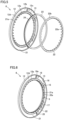
- Fig. 13 is a cross-sectional view showing only sensor unit 6C and magnetic ring 7 in the fourth embodiment.
- Fig. 14 is an exploded perspective view of sensor unit 6C according to the fourth embodiment.
- Fig. 15 is a perspective view of sensor unit 6C according to the fourth embodiment after assembly. In the following, the description of the same configurations as those of sensor unit 6 in the first embodiment will not be repeated.
- Sensor unit 6C includes circuit board 13 and a stator 5C.
- a cage member itself that holds stator 5C is formed by a magnetic member 29 that extends in the radial direction of bearing 2.
- Magnetic member 29 includes a magnetic member 29-1 and a magnetic member 29-2.
- Magnetic member 29-1 has an annular shape and has a U-shaped cross section including an outer circumferential portion 29-1b, an inner circumferential portion 29-1a, and a bottom portion 29-1d connecting outer circumferential portion 29-1b and inner circumferential portion 29-1a.
- Inner circumferential portion 29-1a is formed by a plurality of claw portions 29a.
- Magnetic member 29-2 has an annular shape and has a U-shaped cross section including an outer circumferential portion 29-2b, an inner circumferential portion 29-2a, and a bottom portion 29-2d connecting outer circumferential portion 29-2b and inner circumferential portion 29-2a.
- Inner circumferential portion 29-2a is formed by a plurality of claw portions 29b. The plurality of claw portions 29a and the plurality of claw portions 29b are alternately arranged with a gap interposed therebetween in the circumferential direction.
- Magnetic members 29-1 and 29-2 have outer circumferential portions 29-1b and 29-2b provided with a plurality of protrusions 29c and a plurality of recesses 29d, respectively. By engagement between protrusions 29c and recesses 29d, the plurality of claw portions 29a and the plurality of claw portions 29b are easily positionally aligned. Magnetic member 29 is disposed at one end of bearing 2.
- Bobbin 23 wound with coil 24 is disposed on the inner circumferential side on which the plurality of claw portions 29a and the plurality of claw portions 29b are arranged.
- Circuit board 13 is disposed on the outer circumferential side opposite to coil 24 in the radial direction of bearing 2.
- Circuit board 13 is fixed, for example, to bottom portion 29-1d of magnetic member 29-1 with screws (not shown).
- a hole portion 29e is provided at a position (in bottom portion 29-2d) on the side surface of magnetic member 29-2 that faces the position at which antenna portion 18a of wireless communication circuit 18 is disposed.
- Hole portion 29e is closed by a resin member 30 that is a non-conductive member.
- sensor unit 6C can transmit radio waves of wireless communication to the outside through hole portion 29e, and also, can prevent intrusion of foreign matter into the internal space of magnetic member 29 from the outside, to thereby protect coil 24, circuit board 13, and the like disposed therein.
- a resin sealing material may be introduced through hole portion 29e to cover circuit board 13 and the like with a resin material.
- a plurality of hole portions should only be provided in the circumferential direction in bottom portion 29-2d of magnetic member 29-2, and a resin sealing material should only be introduced through these hole portions to thereby prevent air bubbles from remaining in the internal space of magnetic member 29.
- circuit board 13 is mounted in the internal space formed by magnetic members 29-1 and 29-2. Thereby, circuit board 13 can be protected by magnetic member 29.
- the cage member itself is formed of magnetic member 29-1, and magnetic member 29-2 also serves as a lid, so that the number of components can be reduced.
- outer ring 3 is a stationary ring and inner ring 4 is a rotation ring
- outer ring 3 may be a rotation ring
- inner ring 4 may be a stationary ring.
- magnetic ring 7 should only be fixed to outer ring 3
- sensor units 6, 6A, 6B, and 6C should only be fixed to inner ring 4.
- Bearing device 1 of the present disclosure includes: bearing 2 including outer ring 3, inner ring 4, and rolling element 8; magnetic ring 7 fixed to one of outer ring 3 or inner ring 4; stator 5 disposed to face magnetic ring 7 in the radial direction of bearing 2 and fixed to the other of outer ring 3 or inner ring 4; and circuit board 13.
- Magnetic ring 7 and stator 5 constitute generator G that generates AC power.
- Circuit board 13 includes: at least one sensor (for example, acceleration sensor 15 and temperature sensor 16) that detects the state of bearing 2; wireless communication circuit 18 that wirelessly transmits an output form the at least one sensor to outside; and power supply circuit 17 that converts AC power generated by generator G into DC power usable by the at least one sensor and wireless communication circuit 18.
- Inside the annular space formed by an end portion of outer ring 3 and an end portion of inner ring 4, magnetic ring 7, stator 5, and circuit board 13 are disposed so as not to overlap with each other in the axial direction of bearing 2.
- magnetic ring 7, stator 5, and circuit board 13 are disposed inside the annular space so as not to overlap with each other in the axial direction of bearing 2. Thereby, each component can be disposed inside the annular space, so that the bearing 2 can be reduced in dimensions.
- bearing device 1 for example, magnetic ring 7 is fixed to inner ring 4, and stator 5 is fixed to outer ring 3 at a position facing magnetic ring 7.
- the displacement of inner ring 4 and outer ring 3 in the axial direction of bearing 2 is relatively small, and thereby, the stable amount of power generation can be ensured by generator G, so that the bearing device is reduced in dimensions and still capable of functioning normally.
- the annular space is formed by: first cutout portion 3a formed in the inner circumferential surface at one end of outer ring 3; and second cutout portion 4a formed in the outer circumferential surface at one end of inner ring 4 so as to face first cutout portion 3a.
- each component can be disposed in the annular space formed by first cutout portion 3a and second cutout portion 4a, so that bearing 2 can be reduced in dimensions.
- cage member 12 that holds circuit board 13 and stator 5 is fixed to one of first cutout portion 3a or second cutout portion 4a, and magnetic ring 7 is fixed to the other of first cutout portion 3a or second cutout portion 4a.
- cage member 12 that holds circuit board 13 and stator 5 is fixed to first cutout portion 3a, and magnetic ring 7 is fixed to second cutout portion 4a.
- stator 5 and magnetic ring 7 are fixed to a component with less rattling caused by the use of bearing device 1, and therefore, the stable amount of power generation can be ensured by generator G.
- cage member 12 is a magnetic material having partition wall 12a that partitions cage member 12 into first region 12b and second region 12c in the radial direction of bearing 2. A portion of cage member 12 that includes first region 12b or second region 12c is used as stator 5.
- cage member 12 is divided by partition wall 12a into two regions including first region 12b and second region 12c.
- the portion of cage member 12 that includes first region 12b is used for holding circuit board 13, and the portion of cage member 12 that includes second region 12c also serves as magnetic member 21.
- bearing device 1 the number of components can be reduced, and stator 5 can be firmly fixed to cage member 12.
- cage member 12A has an annular shape and has a U-shaped cross section including outer circumferential portion 12Ab, inner circumferential portion 12Aa, and bottom portion 12Ad connecting outer circumferential portion 12Ab and inner circumferential portion 12Aa.
- Stator 5 is fixed to outer circumferential portion 12Ab or inner circumferential portion 12Aa, and circuit board 13 is fixed to bottom portion 12Ad.
- cage member 12A has a U-shaped cross section and has a simple shape, and thus, can be easily pressed, so that the manufacturing cost can be reduced.
- stator 5B includes coil 24, magnetic member 27 provided with the plurality of claw portions 27d, and magnetic member 28 provided with the plurality of claw portions 28d.
- Coil 24 is accommodated in an internal space formed by combining magnetic members 27 and 28.
- Cage member 12B is magnetic member 27.
- Magnetic member 27 has an annular shape and has a U-shaped cross section including outer circumferential portion 27a, inner circumferential portion 27b, and bottom portion 27c connecting outer circumferential portion 27a and inner circumferential portion 27b.
- Inner circumferential portion 27b is formed by the plurality of claw portions 27d.
- Bottom portion 27c is provided with the plurality of recesses 27e that are spaced apart from each other in the circumferential direction of bearing 2.
- Magnetic member 28 has an annular shape and has a U-shaped cross section including outer circumferential portion 28a, inner circumferential portion 28b, and bottom portion 28c connecting outer circumferential portion 28a and inner circumferential portion 28b.
- Inner circumferential portion 28b is formed by the plurality of claw portions 28d each facing a corresponding one of the plurality of claw portions 27d.
- the plurality of protrusions 28e spaced apart from each other in the circumferential direction of bearing 2 are formed at the end portion in outer circumferential portion 28a in the axial direction of bearing 2.
- the plurality of claw portions 27d and the plurality of claw portions 28d are alternately arranged with a gap interposed therebetween in the circumferential direction of bearing 2.
- cage member 12B functions also as magnetic member 27, and thus, the number of components can be reduced.
- Magnetic members 27 and 28 each have a U-shaped cross section and have a simple shape, and thus, can be easily pressed, so that the manufacturing cost can be reduced.
- a jig does not have to be used to allow coaxial alignment between two magnetic members 27 and 28, and also allow easy positional alignment between the plurality of claw portions 27d and 28d.
- stator 5C includes coil 24, magnetic member 29-1 provided with the plurality of claw portions 29a, and magnetic member 29-2 provided with the plurality of claw portions 29b.
- Coil 24 is accommodated in an internal space formed by combining magnetic members 29-1 and 29-2.
- the cage members are magnetic member 29-1 and magnetic member 29-2.
- Magnetic member 29-1 has an annular shape and has a U-shaped cross section including outer circumferential portion 29-1b, inner circumferential portion 29-1a, and bottom portion 29-1d connecting outer circumferential portion 29-1b and inner circumferential portion 29-1a. Outer circumferential portion 29-1b or inner circumferential portion 29-1a is formed by the plurality of claw portions 29a.
- Magnetic member 29-2 has an annular shape and has a U-shaped cross section including outer circumferential portion 29-2b, inner circumferential portion 29-2a, and bottom portion 29-2d connecting outer circumferential portion 29-2b and inner circumferential portion 29-2a.
- Outer circumferential portion 29-2b or inner circumferential portion 29-2a is formed by the plurality of claw portions 29b.
- Magnetic member 29 is disposed at one end of bearing 2.
- the plurality of claw portions 29a and the plurality of claw portions 29b are alternately arranged with a gap interposed therebetween in the circumferential direction of bearing 2.
- Coil 24 is disposed on the side on which the plurality of claw portions 29a and the plurality of claw portions 29b are located.
- Circuit board 13 is disposed on the side opposite to coil 24 in the radial direction of the bearing.
- Wireless communication circuit 18 includes antenna portion 18a.
- Hole portion 29e is provided at a position of a side surface of magnetic member 29-2 that faces the position at which antenna portion 18a is disposed.
- the cage member itself is formed by magnetic member 29-1, and magnetic member 29-2 also serves as a lid, so that the number of components can be reduced. Further, radio waves of wireless communication can be transmitted to the outside through hole portion 29e, and also, foreign matter can be prevented from intruding into the internal space of magnetic member 29 from the outside, so that coil 24, circuit board 13, and the like provided therein can be protected.
- Bearing device 1 of the present disclosure includes standard bearing 2 as a bearing that includes outer ring 3, inner ring 4, and rolling element 8, the bearing having main dimensions defined under specific standards.
- Bearing device 1 includes: magnetic ring 7 fixed to one of outer ring 3 or inner ring 4; stator 5 disposed to face magnetic ring 7 in the radial direction of standard bearing 2 and fixed to the other of outer ring 3 or inner ring 4; and circuit board 13.
- Magnetic ring 7 and stator 5 constitute generator G that generates AC power.
- Circuit board 13 includes: at least one sensor (for example, acceleration sensor 15 and temperature sensor 16) that detects the state of standard bearing 2; wireless communication circuit 18 that wirelessly transmits an output from the at least one sensor to outside; and power supply circuit 17 that converts AC power generated by generator G into DC power usable by the at least one sensor and wireless communication circuit 18.
- Magnetic ring 7, stator 5, and circuit board 13 are disposed inside an annular space formed by an end portion of outer ring 3 and an end portion of inner ring 4.
- each component can be disposed inside the annular space, so that standard bearing 2 can be reduced in dimensions.
- bearing device 1 for example, magnetic ring 7 is fixed to inner ring 4, and stator 5 is fixed to outer ring 3 at a position facing magnetic ring 7.
- the displacement of inner ring 4 and outer ring 3 in the axial direction of bearing 2 is relatively small, and thus, the stable amount of power generation can be ensured by generator G, so that the bearing device is reduced in dimensions and still capable of functioning normally.
- magnetic ring 7, stator 5, and circuit board 13 are disposed so as not to overlap with each other in the axial direction of standard bearing 2.
- each component can be disposed inside the annular space, so that standard bearing 2 can be reduced in dimensions.
- circuit board 13 has an arc shape.
- the at least one sensor, wireless communication circuit 18, and power supply circuit 17 are disposed on a circumference of circuit board 13 so as not to overlap with each other in the axial direction.
- a plurality of electronic components can be disposed on the circumference of circuit board 13 without increasing the thickness in the axial direction of standard bearing 2, and thus, standard bearing 2 can be reduced in dimensions.
- the specific standards are ISO standards or JIS standards.
- the present invention can be applied to a standard bearing having dimensions defined in ISO standards or JIS standards.
- standard bearing 2 is a radial bearing.
- the main dimensions of the radial bearing are dimensions defined in ISO 15 or JIS B 1512-1.
- the present invention can be applied to a standard bearing having dimensions defined in ISO 15 or JIS B 1512-1.
- a bearing device and a sensor unit according to each of the fifth to eighth embodiments.
- a bearing device including a sensor located adjacent to a bearing is used.
- the bearing device may have a configuration that allows wireless transmission of this data.
- a multipole ring magnet is provided on one axial end face of a cage forming a bearing
- an annular seal is provided to close a space between an inner ring and an outer ring
- a coil for power generation and a wireless processing circuit are mounted on a surface of the annular seal that faces the multipole ring magnet.
- the annular seal is made of metal, the radio waves transmitted from the wireless processing circuit are blocked and cannot be transmitted to the outside of the bearing. This is because the coil for power generation and the wireless processing circuit are disposed to face the inside in the axial direction (toward the rolling element).
- the annular seal is made of non-metal such as a resin or is provided with a slit or the like sufficiently to allow radio waves to pass therethrough, the radio waves can be transmitted to the outside of the bearing. In this case, however, the annular seal is made of resin, and thus, decreased in rigidity. This may impede the operation of the bearing device when it is vibrating.
- An object of the present disclosure is to provide a bearing device that allows stable wireless transmission of radio waves to the outside of the bearing.
- a bearing device includes a bearing and a cage member.
- the bearing includes an outer ring, an inner ring, a rolling element, and a cage that holds a plurality of the rolling elements at intervals in a circumferential direction.
- the cage is shaped to be open on one end face side and to be connected on the other end face side in an axial direction.
- the cage member is disposed at a position on the one end face side across the rolling element from the cage.
- the cage member is fixed to one of the outer ring and the inner ring.
- the cage member is made of metal.
- the cage member includes a side plate portion having a width in a radial direction and extending in the circumferential direction. At least a part of a power supply configured to generate electric power and a circuit board are fixed to the cage member.
- the circuit board is fixed to a surface of the side plate portion on a side not facing the rolling element in the axial direction.
- Fig. 16 is a cross-sectional view of a bearing device 1A according to the fifth embodiment. This corresponds, for example, to a cross-sectional view along a plane including rotation axis O in Fig. 17 in the sixth embodiment described later.
- bearing device 1A in the present embodiment includes bearing 2 and a sensor unit 6D.
- bearing 2 is a standard bearing having axial dimensions defined in specific standards.
- the standard bearing is, for example, a bearing having dimensions defined in ISO standards or JIS standards.
- Bearing 2 is a radial bearing, and its dimension from one end portion to the other end portion in its axial direction is defined in ISO 15 or JIS B 1512-1. In the following, bearing 2 is also referred to as standard bearing 2.
- Bearing 2 includes outer ring 3, inner ring 4, rolling element 8, cage 9, and seal 10.
- outer ring 3 serves as a stationary ring and inner ring 4 serves as a rotation ring.
- bearing 2 should only be selected from those having a size of the model number of the standard bearing having a distance W between end face 11 of bearing 2 and rolling element 8 such that sensor unit 6D can be accommodated within distance W.
- End face 11 is also an end face of outer ring 3.
- a plurality of rolling elements 8 are arranged at intervals in the circumferential direction of bearing 2 (in the depth direction in Fig. 16 ).
- Cage 9 holds the plurality of rolling elements 8.
- Cage 9 is a resin-made member.
- Cage 9 is open on the one end face side (on the right side in Fig. 16 ) in the left-right direction in Fig. 16 that corresponds to the axial direction.
- Cage 9 is connected on the other end face side (on the left side in Fig. 16 ) in the axial direction.
- cage 9 is disposed only in a region substantially on the left side of the center of rolling element 8, and is not disposed in a region on the right side of the center of rolling element 8.
- Sensor unit 6D includes cage member 12, circuit board 13, and lid 14.
- Cage member 12 is a magnetic material and is made of metal.
- Cage member 12 is disposed at a position on the one end face side (on the right side in Fig. 16 ) across rolling element 8 from cage 9. In other words, cage member 12 is disposed on the side where cage 9 is open and is not disposed in the axial direction. Cage member 12 is disposed at a position where cage 9 should originally be disposed.
- Cage member 12 includes a side plate portion 12C.
- Side plate portion 12C has a width sufficient to extend from outer ring 3 to inner ring 4 in the radial direction of bearing 2 (in the vertical direction in Fig. 16 ).
- Side plate portion 12C extends in the circumferential direction, i.e., so as to be formed in an annular shape. In other words, side plate portion 12C extends continuously in the circumferential direction (by one round).
- Cage member 12 is formed of side plate portion 12C and an outside surface and an inside surface in the radial direction.
- Side plate portion 12C is disposed to be adjacent to rolling element 8 at a position of cage member 12 that is closest to rolling element 8 in the axial direction (on the inner side within bearing 2).
- Side plate portion 12C has a rear surface 12g on the side facing rolling element 8, and a front surface 12f on the side opposite to rear surface 12g (i.e., on the side not facing rolling element 8).
- rear surface 12g faces the inner side of bearing 2
- front surface 12f faces the outer side of bearing 2.
- Power supply PWR in Fig. 16 may be, for example, a power supply in any one of the following sixth to eighth embodiments, or may be a power supply of another type. In other words, power supply PWR in Fig. 16 is a generic term of a power supply regardless of the type.
- Circuit board 13 is fixed to front surface 12f of side plate portion 12C of cage member 12.
- Sensor SSR in Fig. 16 may be, for example, a sensor shown in any one of the following sixth to eighth embodiments, or may be a sensor of another type. In other words, sensor SSR in Fig. 16 is a generic term of a sensor regardless of the type.
- Wireless communication circuit 18 is further mounted on circuit board 13.
- Lid 14 is a non-metal (resin-made) sealing member that covers circuit board 13. Lid 14 protects circuit board 13 fixed to cage member 12 and protects the inside of sensor unit 6D. Instead of lid 14, a resin sealing material may be used to seal circuit board 13. Lid 14 also protects members (for example, wireless communication circuit 18, sensor SSR, and the like) other than circuit board 13 that are fixed to front surface 12f of side plate portion 12C.
- cage member 12 The outside surface of cage member 12 on the radially outer side is fitted in and fixed to first cutout portion 3a formed in outer ring 3.
- cage member 12 may be fixed to inner ring 4.
- Cage member 12 is press-fitted or bonded so as not to protrude outward in the axial direction from end face 11 of outer ring 3.
- Cage member 12 may be fixed by both press-fitting and bonding, or may be fixed by other methods.
- Cage member 12 is disposed so as not to protrude outward in the axial direction from end face 11 of outer ring 3, and thereby, circuit board 13 and power supply PWR fixed to cage member 12 are also similarly disposed so as not to protrude outward in the axial direction from end face 11 of outer ring 3.
- cage member 12, circuit board 13, and power supply PWR are preferably disposed so as not to protrude outward in the axial direction from end face 20 of inner ring 4.
- Bearing device 1A includes bearing 2 and cage member 12.
- Bearing 2 includes outer ring 3, inner ring 4, rolling element 8, and cage 9 that holds a plurality of rolling elements 8 at intervals in the circumferential direction.
- Cage 9 is shaped to be open on the one end face side and to be connected on the other end face side in the axial direction.
- Cage member 12 is disposed at a position on the one end face side across rolling element 8 from cage 9.
- Cage member 12 is fixed to one of outer ring 3 and inner ring 4.
- Cage member 12 is made of metal.
- Cage member 12 includes side plate portion 12C having a width in the radial direction and extending in the circumferential direction. At least a part of power supply PWR capable of generating electric power and circuit board 13 are fixed to cage member 12.
- Circuit board 13 is fixed to a surface (front surface 12f) of side plate portion 12C on a side not facing rolling element 8 in the axial direction.
- bearing device 1A In bearing device 1A described above, one end face of cage 9 in the axial direction is opened, so that this opened portion (the portion in which cage 9 is originally disposed) is provided with a space in which circuit board 13, power supply PWR, and the like are disposed. In other words, a space in which circuit board 13 and power supply PWR are disposed is effectively provided inside bearing 2. Further, sensor SSR for detecting the operating state of bearing 2 can be disposed in the above-mentioned space. Thereby, sensor SSR can be disposed at a position significantly close to bearing 2, which makes it possible to detect an abnormality in bearing 2 by sensor SSR with high accuracy.
- Cage member 12 is made of metal, and thereby, can hold circuit board 13 and sensor SSR installed therein so as to ensure high rigidity. Therefore, even when cage member 12 is directly fixed to bearing 2 that is to vibrate, any erroneous operation of sensor SSR can be suppressed. Thus, even in an environment of use in which vibrations are applied, bearing device 1A allows stable monitoring of the state of bearing 2 by sensor SSR and also allows stable wirelessly transmission of data detected by sensor SSR.
- circuit board 13 Since circuit board 13 is fixed to front surface 12f, circuit board 13 is fixed on cage member 12 so as to face the outside of bearing 2. Thus, even if cage member 12 is made of metal, it is possible to suppress a problem that radio waves transmitted from wireless communication circuit 18 or the like mounted on circuit board 13 are blocked and thereby cannot be transmitted to the outside of bearing 2. In other words, wireless transmission of radio waves to the outside of bearing 2 can be stably performed.
- At least one sensor SSR that detects the state of bearing 2 and wireless communication circuit 18 that wirelessly transmits the output from sensor SSR to the outside are mounted on circuit board 13. Thereby, wireless transmission of radio waves to the outside of bearing 2 can be stably performed as described above.
- cage member 12, circuit board 13, and power supply PWR may be disposed so as not to protrude outward in the axial direction from end face 11 of outer ring 3.
- sensor unit 6D can be formed to be thin in the axial direction.
- a bearing device in each of the embodiments the same components as those of the bearing device in each of the above-described embodiments are denoted by the same reference characters, and the description thereof will not be repeated unless there is a difference in configuration and function.
- an electromagnetic induction-type generator is used as power supply PWR provided in bearing device 1A of the fifth embodiment.
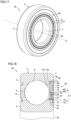
- Fig. 17 is a perspective view of the entirety of a bearing device according to the sixth embodiment. Referring to Fig. 17 , a bearing device 1B includes bearing 2, a sensor unit 6E, and magnetic ring 7.
- Sensor unit 6E includes cage member 12, circuit board 13, lid 14, and stator 5.
- Circuit board 13 is fixed to a radially outer region in side plate portion 12C of cage member 12, and stator 5 is disposed so as to include the entirety of cage member 12.
- Lid 14 is a non-metal resin member and protects the inside of sensor unit 6E. Lid 14 in the present embodiment may be disposed to cover a region other than stator 5 as shown in Fig. 18 . Alternatively, lid 14 may be disposed to cover a region including stator 5. In any case, lid 14 covers circuit board 13.
- Stator 5 includes two magnetic members 21 and 22, bobbin 23, and coil 24. A portion of cage member 12 is used as magnetic member 21 of stator 5.
- Magnetic ring 7 is a magnetic member in which N poles and S poles are alternately magnetized in the circumferential direction.
- Stator 5 is fixed to outer ring 3
- magnetic ring 7 is fixed to inner ring 4.
- Stator 5 and magnetic ring 7 constitute generator G.
- Generator G is a claw pole-type generator but may be a generator having another structure.
- Fig. 17 shows a one-dot chain line indicating rotation axis O of bearing 2.
- Fig. 18 is a cross-sectional view along a plane including the rotation axis of the bearing.
- the inner circumferential surface at one end of outer ring 3 is provided with first cutout portion 3a formed as a stepped portion as in the fifth embodiment.
- the outer circumferential surface at one end of inner ring 4 is provided with second cutout portion 4a formed as a stepped portion so as to face first cutout portion 3a.
- annular recess 50 that is cut out toward rolling element 8 is formed by first cutout portion 3a and second cutout portion 4a so as to extend from outer ring 3 to inner ring 4.
- Magnetic ring 7 includes core metal 7a and multipole magnet 7b.
- Multipole magnet 7b is formed, for example, by kneading magnetic powder with rubber to obtain a magnetic material, which is then vulcanized and bonded to core metal 7a, to which N poles and S poles are alternately magnetized in the circumferential direction of bearing 2.
- Core metal 7a of magnetic ring 7 has flange portion 7c in order to increase rigidity.
- Magnetic ring 7 is fixed to outside surface 4b of inner ring 4 by press-fitting or the like.
- Flange portion 7c is accommodated in second cutout portion 4a provided in inner ring 4.
- Magnetic ring 7 is disposed so as not to protrude from end face 20 of inner ring 4.
- annular recess 50 Inside annular recess 50, magnetic ring 7, stator 5, and circuit board 13 are disposed so as not to overlap with each other in the radial direction of bearing 2. Thereby, each component can be disposed inside this annular recess 50, which makes it possible to reduce the thickness in the axial direction of bearing 2. Further, in bearing device 1B, for example, magnetic ring 7 is fixed to inner ring 4, and stator 5 is fixed to outer ring 3 at a position facing magnetic ring 7. The displacement of inner ring 4 and outer ring 3 in the axial direction of bearing 2 is relatively small as compared with cage 9, and thus, the stable amount of power generation can be ensured by generator G.
- Fig. 19 is a diagram for illustrating cage 9.
- cage 9 is provided with recesses 93 formed at a prescribed pitch in the circumferential direction of end face 91 in the axial direction of the annular cage body.
- a pair of claw portions 94 and 94 are formed to protrude from opening ends of recess 93 that face each other in the circumferential direction of recess 93.
- Recess 93 and the pair of claw portions 94 and 94 form pocket 95 in which rolling element 8 shown in Fig. 18 is accommodated.
- cage 9 is shaped to be open on the end face 91 side as one side and to be connected on the end face 92 side as the other side.
- Cage 9, which is a resin-made member, is disposed on the open side such that sensor unit 6E and magnetic ring 7 do not protrude from end faces 11 and 20.
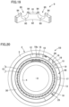
- Fig. 20 is a diagram of bearing device 1B viewed from the sensor unit 6E side. Fig. 20 does not show a part of lid 14 such that the inside of sensor unit 6E can be seen.
- one or more sensors for monitoring the state of bearing 2 are mounted on circuit board 13.
- acceleration sensor 15 and temperature sensor 16 are mounted on circuit board 13.
- an acoustic emission (AE) sensor 26 may also be mounted on circuit board 13.
- AE sensor 26 may be mounted on side plate portion 12C of cage member 12.
- AE sensor 26 may be mounted, for example, in a portion immediately below terminal 25 in Fig. 20 through which side plate portion 12C of cage member 12 is exposed.
- temperature sensor 16 may be inserted through a hole (not shown) provided in side plate portion 12C of cage member 12 and then mounted on the rear surface of circuit board 13 so as to be located close to (or to be in contact with) the end face of first cutout portion 3a of outer ring 3. Thereby, temperature sensor 16 is located close to outer ring 3 and thereby can accurately measure the temperature of bearing 2.
- Power supply circuit 17 rectifies AC power generated by generator G and converts the rectified AC power into DC power.
- power supply circuit 17 is completely different from power supply PWR (see Fig. 16 ), i.e., generator G (an electromagnetic induction-type generator) in the present embodiment.
- the DC power converted by power supply circuit 17 is used in acceleration sensor 15, temperature sensor 16, and wireless communication circuit 18.
- Terminal 25 is disposed on circuit board 13.
- Wireless communication circuit 18 includes antenna portion 18a. Wireless communication circuit 18 wirelessly transmits the outputs from acceleration sensor 15 and temperature sensor 16, which monitor the state of bearing 2, to the outside through antenna portion 18a.
- Circuit board 13 is fixed to cage member 12 with a plurality of screws 19. Circuit board 13 may be bonded and fixed to cage member 12. Circuit board 13 on which wireless communication circuit 18 is mounted is disposed to face lid 14 made of resin. Thereby, wireless communication circuit 18 has a structure not hermetically sealed with a conductive material such as metal. This allows wireless communication through antenna portion 18a in wireless communication circuit 18.
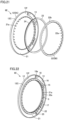
- Fig. 21 is an exploded perspective view of sensor unit 6E according to the sixth embodiment.
- Fig. 22 is a perspective view of sensor unit 6E according to the sixth embodiment after assembly.
- circuit board 13 is fixed to front surface 12f of side plate portion 12C of cage member 12 that does not face rolling element 8.
- Circuit board 13 is disposed in a region of front surface 12f on the relatively outer side in the radial direction.
- Stator 5 includes stators 5A and 5B.
- Stator 5A corresponds to cage member 12 and corresponds to magnetic member 21.
- Stator 5B corresponds to magnetic member 22.
- stator 5A, cage member 12, and magnetic member 21 are the same, and stator 5B and magnetic member 22 are the same.
- Each of magnetic members 21 and 22 has a U-shaped cross section.
- Magnetic member 21 occupies the entirety of cage member 12, whereas magnetic member 22 is disposed in a region of cage member 12 on the radially inner side.
- the region on the radially inner side in the U-shaped cross section of magnetic member 21 faces the U-shaped cross section of magnetic member 22.
- Coil 24 including bobbin 23 is mounted between magnetic members 21 and 22 facing each other so as to be surrounded by magnetic members 21 and 22.
- the plurality of claw portions 21a are formed on an inner circumferential portion of magnetic member 21.
- the plurality of claw portions 22a are formed on an inner circumferential portion of magnetic member 22.
- Coil 24 around which a magnet wire is wound a plurality of times is disposed in a groove provided in bobbin 23 in its circumferential direction.
- Bobbin 23 may not be provided.
- the structure in the above-described fifth embodiment that corresponds to that shown in the perspective view of sensor unit 6E in Fig. 22 does not include stator 5, the plurality of claw portions 21a, and the plurality of claw portions 22a, but other components are the same as those in Fig. 22 .
- stator 5 The following describes an assembly method for stator 5. First, in the state in which bobbin 23 wound with coil 24 is inserted into magnetic member 22, the plurality of claw portions 21a of magnetic member 21 and the plurality of claw portions 22a of magnetic member 22 are assembled to be alternately arranged with a gap interposed therebetween in the circumferential direction. Then, outer circumferential surface 22b of magnetic member 22 is fixed such that its end portion comes into contact with front surface 12f of side plate portion 12C of magnetic member 21. At this time, the openings of magnetic members 21 and 22 face each other, and bobbin 23 and coil 24 are accommodated in these openings.
- the plurality of claw portions 21a of magnetic member 21 and the plurality of claw portions 22a of magnetic member 22 are disposed to face each other while ensuring a gap between each of claw portions 21a, 22a and multipole magnet 7b of magnetic ring 7 shown in Fig. 18 .
- Claw pole-type generator G is formed by magnetic ring 7 and the plurality of claw portions 21a of magnetic member 21 and the plurality of claw portions 22a of magnetic member 22 in stator 5.
- the total number of the plurality of claw portions 21a and 22a is equal to the number of poles (the total number of the N and S poles) in multipole magnet 7b.
- the magnetic flux emitted from the N pole of multipole magnet 7b flows from the plurality of claw portions 21a (or the plurality of claw portions 22a), each of which is a magnetic pole, into magnetic member 21 (or magnetic member 22), flows around coil 24, and passes through the plurality of claw portions 22a (or the plurality of claw portions 21a) adjacent thereto, and then flows back to the S pole of multipole magnet 7b.
- the positions of the N pole and the S pole of multipole magnet 7b are replaced with each other by the rotation of inner ring 4, the direction of the magnetic flux is reversed.
- the alternating magnetic field generated in this way generates AC power at both ends of coil 24.
- Each of the ends (not shown) of the winding start and the winding end of coil 24 pulled out of stator 5 is connected to terminal 25 provided on circuit board 13.
- the AC power output from generator G by the rotation of inner ring 4 is converted into DC power by power supply circuit 17.
- Sensor unit 6E of bearing device 1B may be divided by a partition wall (not shown) into two regions in the radial direction of cage member 12. Also in this case, similarly to the above, circuit board 13 is disposed in the region on the outer side in the radial direction, and stator 5 in claw pole-type generator G is disposed in the region on the inner side. Magnetic ring 7 is disposed on side of the inside diameter to face stator 5.
- Bearing device 1B in the present embodiment has the following features in addition to the configuration in the fifth embodiment.
- Power supply PWR (see Fig. 16 ) is an electromagnetic induction-type generator (generator G) including: magnetic ring 7 fixed to the other one different from one of outer ring 3 and inner ring 4; and coil 24 mounted on cage member 12 to face magnetic ring 7 in the radial direction of bearing 2.
- generator G electromagnetic induction-type generator
- multipole magnet 7b a plurality of permanent magnets may be fixed to magnetic ring 7, or a magnetic body having a plurality of magnetic poles may be fixed to magnetic ring 7.
- stator 5 and magnetic ring 7 are disposed in the radial direction to constitute claw pole-type generator G.
- generator G Since the electric power generated in this case can be used in wireless communication circuit 18, wireless transmission of radio waves to the outside of bearing 2 can be stably performed.
- Generator G as a power supply is an electromagnetic induction-type generator, which includes magnetic ring 7 and stator 5.
- Stator 5 is fixed to cage member 12. This is because cage member 12 is stator 5A that is a part of stator 5, and bobbin 23 and coil 24 constituting stator 5 are fixed to cage member 12.
- magnetic ring 7 faces stator 5 and is fixed to the side of inner ring 4 serving as a rotation ring. In other words, magnetic ring 7 is not fixed to cage member 12. Therefore, only members of generator G excluding magnetic ring 7 are fixed to cage member 12.
- At least one sensor SSR in bearing device 1B of the present embodiment includes at least one included in a group consisting of acceleration sensor 15, temperature sensor 16, and AE sensor 26.
- bearing device 1B can detect at least one of the acceleration, the temperature, and the vibration (an AE wave) of the rotation of bearing 2.
- Fig. 23 is a perspective view of a sensor unit 6F according to the seventh embodiment.
- a storage battery 31 is used as power supply PWR provided in bearing device 1A according to the fifth embodiment.
- Storage battery 31 is fixed to front surface 12f of side plate portion 12C of cage member 12.
- storage battery 31 preferably has, for example, an arc-shaped planar shape so as to coincide with the shape of front surface 12f.
- Storage battery 31 may be configured such that a plurality of power storage elements are mounted on a substrate.
- Storage battery 31 corresponds to electromagnetic induction-type generator G in the sixth embodiment. However, generator G generates AC power, whereas storage battery 31 generates DC power.
- power supply circuit 17 in the present embodiment does not have a function of rectifying AC power to DC power as in the sixth embodiment.
- Power supply circuit 17 in the present embodiment controls the voltage value to reach a target value by stepping up and stepping down of the voltage.
- Fig. 24 is a perspective view of a sensor unit 6G according to the eighth embodiment.
- a power feeding device 34 is used that includes: a power reception circuit 32 and a power transmission circuit 33 that contactlessly transmits a signal to power reception circuit 32.
- Power reception circuit 32 is fixed to front surface 12f of side plate portion 12C of cage member 12.
- (the substrate of) power reception circuit 32 preferably has, for example, an arc-shaped planar shape so as to coincide with the shape of front surface 12f.
- Power feeding device 34 corresponds to storage battery 31 in the seventh embodiment, and has the same function as that of storage battery 31.
- a bearing device includes: a bearing including an outer ring, an inner ring, a rolling element, and a cage that holds a plurality of the rolling elements at intervals in a circumferential direction; and a cage member.
- the cage is shaped to be open on one end face side and to be connected on the other end face side in an axial direction, the cage member is disposed at a position on the one end face side across the rolling element from the cage, the cage member is fixed to one of the outer ring and the inner ring, the cage member is made of metal, the cage member includes a side plate portion having a width in a radial direction and extending in the circumferential direction, at least a part of a power supply configured to generate electric power and a circuit board are fixed to the cage member, and the circuit board is fixed to a surface of the side plate portion on a side not facing the rolling element in the axial direction.
- At least one sensor that detects the state of the bearing and a wireless communication circuit that wirelessly transmits an output from the sensor to the outside are mounted on the circuit board.
- the at least one sensor includes at least one included in a group consisting of an acceleration sensor, a temperature sensor, and an AE sensor.
- the power supply is an electromagnetic induction-type generator including: a magnetic ring fixed to the other one different from one of the outer ring and the inner ring; and a coil attached to the cage member so as to face the magnetic ring in a radial direction of the bearing.
- the power supply is a storage battery.
- the power supply is a power feeding device including: a power reception circuit; and a power transmission circuit that contactlessly transmits a signal to the power reception circuit.
- the power reception circuit is mounted on the cage member.
- the cage member, the circuit board, and the power supply are disposed so as not to protrude outward in the axial direction from an end face of the outer ring.
Landscapes
- Engineering & Computer Science (AREA)
- General Engineering & Computer Science (AREA)
- Mechanical Engineering (AREA)
- Power Engineering (AREA)
- Rolling Contact Bearings (AREA)
Abstract
Description
- The present disclosure relates to a bearing device.
- There is known a bearing device formed of a combination of a bearing and a generator and used as a power supply for a sensor, wireless communication, and the like.
-
Japanese Patent Laying-Open No. 2017-72170 PTL 1 has a structure in which a multipole ring magnet is fixed to one end of a cage holding a rolling element, and a coil is disposed on a seal side facing the multipole ring magnet. In the bearing device disclosed inPTL 1, electric power is generated by relative rotation of the multipole ring magnet and the coil that are disposed in the axial direction. - PTL 1:
Japanese Patent Laying-Open No. 2017-72170 - In this case, due to its use, the cage significantly rattles in the axial direction of the bearing. For this reason, in the bearing device in
PTL 1, the gap between the multipole ring magnet and the coil in the axial direction tends to vary due to such rattling of the cage caused by its use. In the bearing device inPTL 1, it is conceivable that, when the gap becomes larger, the amount of power generation decreases, which exerts an influence upon the driving of electronic components such as a sensor. In the bearing device inPTL 1, it is conceivable that, when the gap becomes smaller, the multipole ring magnet comes into contact with electronic components such as a sensor. - The present disclosure has been made to solve the above-described problems, an object thereof is to provide a bearing device that is reduced in dimensions and still capable of functioning normally.
- A bearing device of the present disclosure includes: a standard bearing as a bearing that includes an outer ring, an inner ring, and a rolling element, the bearing having main dimensions defined under specific standards. The bearing device includes: a magnetic ring fixed to one of the outer ring or the inner ring; a stator disposed to face the magnetic ring in a radial direction of the standard bearing and fixed to the other of the outer ring or the inner ring; and a circuit board. The magnetic ring and the stator constitute a generator that generates alternating-current (AC) power. The circuit board includes: at least one sensor that detects a state of the standard bearing; a wireless communication circuit that wirelessly transmits an output from the at least one sensor to outside; and a power supply circuit that converts AC power generated by the generator into direct-current (DC) power usable in the at least one sensor and the wireless communication circuit. The magnetic ring, the stator, and the circuit board are disposed inside an annular space formed by a recess in an end portion of the outer ring and a recess in an end portion of the inner ring.
- According to the bearing device of the present disclosure, the magnetic ring, the stator, and the circuit board are disposed inside the annular space so as not to overlap with each other in the axial direction of the bearing. Thereby, each component can be disposed inside the annular space, so that the bearing can be reduced in dimensions. Further, in the bearing device of the present disclosure, for example, the magnetic ring is fixed to the inner ring, and the stator is fixed to the outer ring at the position facing the magnetic ring. The displacement of the inner ring and the outer ring in the axial direction of the bearing is relatively small, and the magnetic ring and the stator constitute the generator, with the result that the bearing device is reduced in dimensions and still capable of functioning normally.
-
-
Fig. 1 is a perspective view showing an entirety of a bearing device according to a first embodiment. -
Fig. 2 is a cross-sectional view along a plane including a rotation axis of a bearing. -
Fig. 3 is a diagram for illustrating a cage. -
Fig. 4 is a diagram of the bearing device viewed from the side of a sensor unit. -
Fig. 5 is an exploded perspective view of the sensor unit. -
Fig. 6 is a perspective view of the sensor unit after assembly. -
Fig. 7 is a cross-sectional view showing only a sensor unit and a magnetic ring in a second embodiment. -
Fig. 8 is an exploded perspective view of the sensor unit according to the second embodiment. -
Fig. 9 is a perspective view of the sensor unit according to the second embodiment after assembly. -
Fig. 10 is a cross-sectional view showing only a sensor unit and a magnetic ring in a third embodiment. -
Fig. 11 is an exploded perspective view of the sensor unit according to the third embodiment. -
Fig. 12 is a perspective view of the sensor unit according to the third embodiment after assembly. -
Fig. 13 is a cross-sectional view showing only a sensor unit and a magnetic ring in a fourth embodiment. -
Fig. 14 is an exploded perspective view of the sensor unit according to the fourth embodiment. -
Fig. 15 is a perspective view of the sensor unit according to the fourth embodiment after assembly. -
Fig. 16 is a cross-sectional view of a bearing device according to a fifth embodiment. -
Fig. 17 is a perspective view of an entirety of a bearing device according to a sixth embodiment. -
Fig. 18 is a cross-sectional view along a plane including a rotation axis of a bearing. -
Fig. 19 is a diagram for illustrating a cage. -
Fig. 20 is a diagram of the bearing device viewed from the side of a sensor unit. -
Fig. 21 is an exploded perspective view of a sensor unit according to the sixth embodiment. -
Fig. 22 is a perspective view of the sensor unit according to the sixth embodiment after assembly. -
Fig. 23 is a perspective view of a sensor unit according to a seventh embodiment. -
Fig. 24 is a perspective view of a sensor unit according to an eighth embodiment. - Hereinafter, embodiments of the present disclosure will be described in detail with reference to the accompanying drawings. In the embodiments described below, when the number, the quantity and the like are mentioned, the scope of the present disclosure is not necessarily limited thereto unless otherwise specified. The same or corresponding components are denoted by the same reference characters, and the description thereof may not be repeated. It has been originally intended to use an appropriate combination of configurations in the embodiments.
-
Fig. 1 is a perspective view showing the entirety of abearing device 1 according to the first embodiment.Bearing device 1 includes abearing 2, asensor unit 6, and amagnetic ring 7.Bearing 2 includes anouter ring 3 and aninner ring 4. Inbearing 2, for example,outer ring 3 serves as a stationary ring andinner ring 4 serves as a rotation ring. Although a deep groove ball bearing will be described as an example of bearing 2, the type ofbearing 2 is not limited to such a deep groove ball bearing. - In this case,
bearing 2 is a standard bearing as a bearing whose main dimensions (an inside diameter, an outside diameter, a width, and the like) are defined in specific standards. The standard bearing is a bearing having dimensions defined, for example, in ISO standards or JIS standards.Bearing 2 is a radial bearing and has main dimensions defined in ISO 15 or JIS B 1512-1. In the following, bearing 2 is also referred to as astandard bearing 2. -
Sensor unit 6 includes astator 5 and alid 14. The structure ofstator 5 will be described later in detail.Lid 14 is a non-metal resin member and protects the inside ofsensor unit 6.Magnetic ring 7 is a magnetic member in which N poles and S poles are alternately magnetized in the circumferential direction.Stator 5 is fixed toouter ring 3, andmagnetic ring 7 is fixed toinner ring 4.Stator 5 andmagnetic ring 7 constitute a generator G. Generator G is a claw pole-type generator but may be a generator having another structure.Fig. 1 shows a one-dot chain line indicating a rotation axis O ofbearing 2. -
Fig. 2 is a cross-sectional view along a plane including rotation axis O ofbearing 2.Bearing 2 includesouter ring 3,inner ring 4, a rollingelement 8, acage 9, and aseal 10.Bearing 2 should only be selected from those having a size of the model number of the standard bearing having a distance W between anend face 11 ofbearing 2 and rollingelement 8 such thatsensor unit 6 andmagnetic ring 7 can be accommodated within distance W. End face 11 is also an end face ofouter ring 3. - An inner circumferential surface at one end of
outer ring 3 has afirst cutout portion 3a provided as a stepped portion and formed as a recess in an end portion ofouter ring 3. An outer circumferential surface at one end ofinner ring 4 has asecond cutout portion 4a provided as a stepped portion and formed as a recess in an end portion ofinner ring 4 so as to facefirst cutout portion 3a. In the axial direction (also referred to as axially) ofbearing 2, an annular space by anannular recess 50 that is cut out toward rollingelement 8 is formed byfirst cutout portion 3a andsecond cutout portion 4a so as to extend fromouter ring 3 toinner ring 4. -
Sensor unit 6 includes acage member 12, acircuit board 13,stator 5, andlid 14.Cage member 12 is a magnetic material having apartition wall 12a thatpartitions cage member 12 into afirst region 12b and asecond region 12c in a radial direction (also referred to as radially) ofbearing 2.Circuit board 13 is fixed to aninner bottom surface 12d offirst region 12b, andstator 5 is disposed insecond region 12c.Lid 14 protectscircuit board 13 fixed toinner bottom surface 12d. Instead oflid 14, a resin sealing material may be used to sealcircuit board 13. - The outside surface of
cage member 12 on thefirst region 12b side is fitted in and fixed tofirst cutout portion 3a formed inouter ring 3.Cage member 12 is press-fitted or bonded so as not to protrude from end face 11 ofouter ring 3.Cage member 12 may be fixed by both press-fitting and bonding, or may be fixed by other methods. Whencage member 12 is fixed tofirst cutout portion 3a, a certain gap is ensured between rollingelement 8 andcage member 12. Thereby, even when displacement in the axial direction occurs between rollingelement 8 andcage member 12, the gap can prevent contact between rollingelement 8 andcage member 12. -
Stator 5 includes twomagnetic members bobbin 23, and acoil 24. A portion ofcage member 12 that includessecond region 12c is used asmagnetic member 21 ofstator 5. -
Magnetic ring 7 includes acore metal 7a and amultipole magnet 7b.Multipole magnet 7b is formed, for example, by kneading magnetic powder with rubber to obtain a magnetic material, which is then vulcanized and bonded tocore metal 7a, to which N poles and S poles are alternately magnetized in the circumferential direction ofbearing 2.Core metal 7a ofmagnetic ring 7 has aflange portion 7c in order to increase rigidity.Magnetic ring 7 is fixed to anoutside surface 4b ofinner ring 4 by press-fitting or the like.Flange portion 7c is accommodated insecond cutout portion 4a provided ininner ring 4.Magnetic ring 7 is disposed so as not to protrude from end face 20 ofinner ring 4. - Inside
annular recess 50,magnetic ring 7,stator 5, andcircuit board 13 are disposed so as not to overlap with each other in the axial direction ofbearing 2. Thereby, each component can be disposed inside thisannular recess 50, so that bearing 2 can be reduced in dimensions. Further, in bearingdevice 1, for example,magnetic ring 7 is fixed toinner ring 4, andstator 5 is fixed toouter ring 3 at a position facingmagnetic ring 7. The displacement ofinner ring 4 andouter ring 3 in the axial direction of bearing 2 is relatively small as compared withcage 9, and thus, the stable amount of power generation can be ensured by generator G, and the bearing device is reduced in dimensions and still capable of functioning normally. -
Fig. 3 is a diagram for illustratingcage 9.Cage 9 is provided withrecesses 93 formed at a prescribed pitch in the circumferential direction of anend face 91 in the axial direction of the annular cage body. A pair ofclaw portions recess 93 that face each other in the circumferential direction ofrecess 93.Recess 93 and the pair ofclaw portions pocket 95 in which rollingelement 8 shown inFig. 2 is accommodated. In this way,cage 9 is shaped to be open on theend face 91 side as one side and to be connected on the side of anend face 92 as the other side.Cage 9, which is a resin-made member, is disposed on the open side such thatsensor unit 6 andmagnetic ring 7 do not protrude from end faces 11 and 20. -
Fig. 4 is a diagram of bearingdevice 1 viewed from thesensor unit 6 side.Fig. 4 does not show a part oflid 14 such that the inside ofsensor unit 6 can be seen. One or more sensors for monitoring the state of bearing 2 are mounted oncircuit board 13. For example, anacceleration sensor 15 and atemperature sensor 16 are mounted oncircuit board 13. Note thattemperature sensor 16 may be inserted through a hole (not shown) provided ininner bottom surface 12d ofcage member 12 and then mounted on the rear surface ofcircuit board 13 so as to be located close to (or to be in contact with) the end face offirst cutout portion 3a ofouter ring 3. Thereby,temperature sensor 16 is located close toouter ring 3 and thereby can accurately measure the temperature ofbearing 2. - On
circuit board 13, apower supply circuit 17 and awireless communication circuit 18 are further mounted.Power supply circuit 17 rectifies AC power generated by generator G and converts the rectified AC power into DC power. The DC power converted bypower supply circuit 17 is used inacceleration sensor 15,temperature sensor 16, andwireless communication circuit 18. A terminal 25 is disposed oncircuit board 13. -
Wireless communication circuit 18 includes anantenna portion 18a.Wireless communication circuit 18 wirelessly transmits the outputs fromacceleration sensor 15 andtemperature sensor 16, which monitor the state of bearing 2, to the outside throughantenna portion 18a.Circuit board 13 is fixed tocage member 12 with a plurality ofscrews 19.Circuit board 13 may be bonded and fixed tocage member 12.Circuit board 13 on whichwireless communication circuit 18 is mounted is disposed to facelid 14 made of resin. Thereby,wireless communication circuit 18 has a structure not hermetically sealed with a conductive material such as metal. This allows wireless communication throughantenna portion 18a inwireless communication circuit 18. -
Fig. 5 is an exploded perspective view ofsensor unit 6.Fig. 6 is a perspective view ofsensor unit 6 after assembly.Sensor unit 6 includescage member 12,circuit board 13, andstator 5.Circuit board 13 is fixed toinner bottom surface 12d offirst region 12b ofcage member 12.Stator 5 is disposed insecond region 12c ofcage member 12.Stator 5 includes twomagnetic members bobbin 23, andcoil 24. A part ofcage member 12 that includespartition wall 12a ofsecond region 12c is used asmagnetic member 21 ofstator 5. - Each of
magnetic members claw portions 21a are formed on an inner circumferential portion ofmagnetic member 21. A plurality ofclaw portions 22a are formed on an inner circumferential portion ofmagnetic member 22.Coil 24 around which a magnet wire is wound a plurality of times is disposed in a groove provided inbobbin 23 in its circumferential direction.Bobbin 23 may not be provided. - The following describes an assembly method for
stator 5. First, in the state in which bobbin 23 wound withcoil 24 is inserted intomagnetic member 22, the plurality ofclaw portions 21a ofmagnetic member 21 and the plurality ofclaw portions 22a ofmagnetic member 22 are assembled to be alternately arranged with a gap interposed therebetween in the circumferential direction. Then, an outercircumferential surface 22b ofmagnetic member 22 is fixed to be fitted in the inner circumferential surface ofpartition wall 12a ofmagnetic member 21. - The plurality of
claw portions 21a ofmagnetic member 21 and the plurality ofclaw portions 22a ofmagnetic member 22 are disposed to respectively face each other while ensuring a gap between each ofclaw portions multipole magnet 7b ofmagnetic ring 7 shown inFig. 2 . Claw pole-type generator G is formed bymagnetic ring 7, and the plurality ofclaw portions 21a ofmagnetic member 21 and the plurality ofclaw portions 22a ofmagnetic member 22 instator 5. The total number of the plurality ofclaw portions multipole magnet 7b. - The magnetic flux emitted from the N pole of
multipole magnet 7b flows, for example, from the plurality ofclaw portions 21a (or the plurality ofclaw portions 22a) each serving as a magnetic pole into magnetic member 21 (or magnetic member 22), flows aroundcoil 24, and passes through the plurality ofclaw portions 22a (or the plurality ofclaw portions 21a) adjacent thereto, and then flows back to the S pole ofmultipole magnet 7b. When the positions of the N pole and the S pole ofmultipole magnet 7b are replaced with each other by the rotation ofinner ring 4, the direction of the magnetic flux is reversed. The alternating magnetic field generated in this way generates AC power at both ends ofcoil 24. - Each of the ends (not shown) of the winding start and the winding end of
coil 24 pulled out ofstator 5 is connected to terminal 25 provided oncircuit board 13. The AC power output from generator G by the rotation ofinner ring 4 is converted into DC power bypower supply circuit 17. -
Sensor unit 6 of bearingdevice 1 is divided bypartition wall 12a intofirst region 12b andsecond region 12c in the radial direction ofcage member 12.Circuit board 13 is disposed infirst region 12b, andstator 5 in claw pole-type generator G is disposed insecond region 12c.Magnetic ring 7 is disposed on the side of the inside diameter to facestator 5. - As described above, bearing
device 1 is structured such thatcircuit board 13,stator 5, andmagnetic ring 7 are sequentially disposed so as not to overlap with each other in the axial direction ofbearing 2. Further, bearingdevice 1 is shaped such thatsensor unit 6 does not protrude from end face 11 ofbearing 2, and also shaped such thatmagnetic ring 7 does not protrude from end face 20 ofinner ring 4. Thereby, in bearingdevice 1,sensor unit 6 can be formed to be thin in the axial direction. - In bearing
device 1,stator 5 andmagnetic ring 7 are disposed in the radial direction to constitute claw pole-type generator G. Thus,stator 5 andmagnetic ring 7 are fixed to a component with less rattling caused by the use of bearingdevice 1, and thereby, the stable amount of power generation can be ensured by generator G. - In this case,
cage member 12 is divided bypartition wall 12a into two regions includingfirst region 12b andsecond region 12c. The portion ofcage member 12 that includesfirst region 12b is used for holdingcircuit board 13, and the portion ofcage member 12 that includessecond region 12c is used also asmagnetic member 21. Thus, in bearingdevice 1, the number of components can be reduced, andstator 5 can be firmly fixed tocage member 12. - In the second embodiment, a
sensor unit 6A different in structure fromsensor unit 6 in the first embodiment will be described.Fig. 7 is a cross-sectional view showingonly sensor unit 6A andmagnetic ring 7 in the second embodiment.Fig. 8 is an exploded perspective view ofsensor unit 6A according to the second embodiment.Fig. 9 is a perspective view ofsensor unit 6A according to the second embodiment after assembly. In the following, the description of the same configurations as those ofsensor unit 6 in the first embodiment will not be repeated. -
Sensor unit 6A includes acage member 12A,circuit board 13, astator 5A, andlid 14.Cage member 12A does not havepartition wall 12a in the first embodiment.Cage member 12A has an annular shape and has a U-shaped cross section including an outer circumferential portion 12Ab, an inner circumferential portion 12Aa, and a bottom portion 12Ad connecting outer circumferential portion 12Ab and inner circumferential portion 12Aa.Stator 5A is fixed to the side surface of inner circumferential portion 12Aa by press-fitting.Stator 5A may be fixed by bonding, or may be fixed by both press-fitting and bonding.Circuit board 13 is fixed to bottom portion 12Ad ofcage member 12A. -
Stator 5A includes amagnetic member 26,bobbin 23, andcoil 24.Magnetic member 26 includes a magnetic member 26-1 and a magnetic member 26-2. Each of magnetic members 26-1 and 26-2 has a U-shaped cross section. Magnetic member 26-1 has an inner circumferential portion provided with a plurality ofclaw portions 26a. Magnetic member 26-2 has an inner circumferential portion provided with a plurality ofclaw portions 26b. The plurality ofclaw portions 26a and the plurality ofclaw portions 26b are alternately arranged with a gap interposed therebetween in the circumferential direction. - Magnetic members 26-1 and 26-2 have outer circumferential portions provided with a plurality of
recesses 26c and a plurality ofprotrusions 26d, respectively. By engagement betweenrecesses 26c andprotrusions 26d, the plurality ofclaw portions 26a and the plurality ofclaw portions 26b are easily positionally aligned. -
Cage member 12A and magnetic members 26-1 and 26-2 each have a U-shaped cross section and have a simple shape, and thus, can be easily pressed, so that the manufacturing cost can be reduced. - In the third embodiment, a
sensor unit 6B different in structure fromsensor unit 6 in the first embodiment will be described.Fig. 10 is a cross-sectional view showingonly sensor unit 6B andmagnetic ring 7 in the third embodiment.Fig. 11 is an exploded perspective view ofsensor unit 6B according to the third embodiment.Fig. 12 is a perspective view ofsensor unit 6B according to the third embodiment after assembly. In the following, the description of the same configurations as those ofsensor unit 6 in the first embodiment will not be repeated. -
Sensor unit 6B includes acage member 12B,circuit board 13, astator 5B, andlid 14.Cage member 12B ofsensor unit 6B has a function of fixingcircuit board 13 and a function as amagnetic member 27 ofstator 5B.Cage member 12B (magnetic member 27) has an annular shape and has a U-shaped cross section including an outercircumferential portion 27a, an innercircumferential portion 27b, and abottom portion 27c connecting outercircumferential portion 27a and innercircumferential portion 27b. Innercircumferential portion 27b is formed by a plurality ofclaw portions 27d.Bottom portion 27c is provided with a plurality ofrecesses 27e that are spaced apart from each other in the circumferential direction ofbearing 2. -
Stator 5B includes amagnetic member 28.Magnetic member 28 has an annular shape and has a U-shaped cross section including an outercircumferential portion 28a, an innercircumferential portion 28b, and abottom portion 28c connecting outercircumferential portion 28a and innercircumferential portion 28b. Innercircumferential portion 28b is formed by a plurality ofclaw portions 28d each facing a corresponding one of the plurality ofclaw portions 27d ofmagnetic member 27. A plurality ofprotrusions 28e spaced apart from each other in the circumferential direction of bearing 2 are formed at an end portion in outercircumferential portion 28a in the axial direction ofbearing 2. - The following describes an assembly method for
stator 5B. In the state in which bobbin 23 wound withcoil 24 is inserted intomagnetic member 28,protrusions 28e ofmagnetic member 28 are respectively engaged withrecesses 27e ofmagnetic member 27. By the engagement between the plurality ofrecesses 27e and the plurality ofprotrusions 28e, the plurality ofclaw portions 27d ofmagnetic member 27 and the plurality ofclaw portions 28d ofmagnetic member 28 are alternately arranged with a gap interposed therebetween in the circumferential direction. The plurality ofrecesses 27e and the plurality ofprotrusions 28e allow easy positional alignment between the plurality ofclaw portions 27d and the plurality ofclaw portions 28d. The end face ofmagnetic member 28 excludingprotrusions 28e abuts onbottom portion 27c ofmagnetic member 27. - Each of
recesses 27e ofmagnetic member 27 and each ofprotrusions 28e ofmagnetic member 28 are fixed by press-fitting. However, eachrecess 27e and eachprotrusion 28e may be fixed by bonding or by laser welding. Alternatively, eachrecess 27e and eachprotrusion 28e may be fixed in combination of press-fitting, bonding, and welding. By engagement between eachrecess 27e and eachprotrusion 28e, a jig does not have to be used to allow coaxial alignment between twomagnetic members claw portions more recesses 27e and three ormore protrusions 28e are preferably formed. -
Cage member 12B functions also asmagnetic member 27, and thus, the number of components can be reduced.Magnetic members - Note that recesses 27e and
protrusions 28e may not be provided. In this case, in the state in which a jig (not shown) is used to achieve the coaxial alignment betweenmagnetic members claw portions bottom portion 27c ofmagnetic member 27 and the end portion of outercircumferential portion 28a ofmagnetic member 28 may be fixed by laser welding or the like. - In the fourth embodiment, a
sensor unit 6C different in structure fromsensor unit 6 in the first embodiment will be described.Fig. 13 is a cross-sectional view showingonly sensor unit 6C andmagnetic ring 7 in the fourth embodiment.Fig. 14 is an exploded perspective view ofsensor unit 6C according to the fourth embodiment.Fig. 15 is a perspective view ofsensor unit 6C according to the fourth embodiment after assembly. In the following, the description of the same configurations as those ofsensor unit 6 in the first embodiment will not be repeated. -
Sensor unit 6C includescircuit board 13 and astator 5C. Insensor unit 6C, a cage member itself that holdsstator 5C is formed by amagnetic member 29 that extends in the radial direction ofbearing 2.Magnetic member 29 includes a magnetic member 29-1 and a magnetic member 29-2. Magnetic member 29-1 has an annular shape and has a U-shaped cross section including an outer circumferential portion 29-1b, an inner circumferential portion 29-1a, and a bottom portion 29-1d connecting outer circumferential portion 29-1b and inner circumferential portion 29-1a. Inner circumferential portion 29-1a is formed by a plurality ofclaw portions 29a. - Magnetic member 29-2 has an annular shape and has a U-shaped cross section including an outer circumferential portion 29-2b, an inner circumferential portion 29-2a, and a bottom portion 29-2d connecting outer circumferential portion 29-2b and inner circumferential portion 29-2a. Inner circumferential portion 29-2a is formed by a plurality of
claw portions 29b. The plurality ofclaw portions 29a and the plurality ofclaw portions 29b are alternately arranged with a gap interposed therebetween in the circumferential direction. - Magnetic members 29-1 and 29-2 have outer circumferential portions 29-1b and 29-2b provided with a plurality of
protrusions 29c and a plurality ofrecesses 29d, respectively. By engagement betweenprotrusions 29c and recesses 29d, the plurality ofclaw portions 29a and the plurality ofclaw portions 29b are easily positionally aligned.Magnetic member 29 is disposed at one end ofbearing 2. -
Bobbin 23 wound withcoil 24 is disposed on the inner circumferential side on which the plurality ofclaw portions 29a and the plurality ofclaw portions 29b are arranged.Circuit board 13 is disposed on the outer circumferential side opposite tocoil 24 in the radial direction ofbearing 2.Circuit board 13 is fixed, for example, to bottom portion 29-1d of magnetic member 29-1 with screws (not shown). Ahole portion 29e is provided at a position (in bottom portion 29-2d) on the side surface of magnetic member 29-2 that faces the position at whichantenna portion 18a ofwireless communication circuit 18 is disposed. -
Hole portion 29e is closed by aresin member 30 that is a non-conductive member. Thereby,sensor unit 6C can transmit radio waves of wireless communication to the outside throughhole portion 29e, and also, can prevent intrusion of foreign matter into the internal space ofmagnetic member 29 from the outside, to thereby protectcoil 24,circuit board 13, and the like disposed therein. Further, a resin sealing material may be introduced throughhole portion 29e to covercircuit board 13 and the like with a resin material. In this case, a plurality of hole portions should only be provided in the circumferential direction in bottom portion 29-2d of magnetic member 29-2, and a resin sealing material should only be introduced through these hole portions to thereby prevent air bubbles from remaining in the internal space ofmagnetic member 29. - In
sensor unit 6C,circuit board 13 is mounted in the internal space formed by magnetic members 29-1 and 29-2. Thereby,circuit board 13 can be protected bymagnetic member 29. Insensor unit 6C, the cage member itself is formed of magnetic member 29-1, and magnetic member 29-2 also serves as a lid, so that the number of components can be reduced. - The above embodiments have been described with regard to the example in which
outer ring 3 is a stationary ring andinner ring 4 is a rotation ring, butouter ring 3 may be a rotation ring andinner ring 4 may be a stationary ring. In this case,magnetic ring 7 should only be fixed toouter ring 3, andsensor units inner ring 4. -
Bearing device 1 of the present disclosure includes: bearing 2 includingouter ring 3,inner ring 4, and rollingelement 8;magnetic ring 7 fixed to one ofouter ring 3 orinner ring 4;stator 5 disposed to facemagnetic ring 7 in the radial direction of bearing 2 and fixed to the other ofouter ring 3 orinner ring 4; andcircuit board 13.Magnetic ring 7 andstator 5 constitute generator G that generates AC power.Circuit board 13 includes: at least one sensor (for example,acceleration sensor 15 and temperature sensor 16) that detects the state of bearing 2;wireless communication circuit 18 that wirelessly transmits an output form the at least one sensor to outside; andpower supply circuit 17 that converts AC power generated by generator G into DC power usable by the at least one sensor andwireless communication circuit 18. Inside the annular space formed by an end portion ofouter ring 3 and an end portion ofinner ring 4,magnetic ring 7,stator 5, andcircuit board 13 are disposed so as not to overlap with each other in the axial direction ofbearing 2. - By providing such a configuration,
magnetic ring 7,stator 5, andcircuit board 13 are disposed inside the annular space so as not to overlap with each other in the axial direction ofbearing 2. Thereby, each component can be disposed inside the annular space, so that thebearing 2 can be reduced in dimensions. Further, in bearingdevice 1, for example,magnetic ring 7 is fixed toinner ring 4, andstator 5 is fixed toouter ring 3 at a position facingmagnetic ring 7. The displacement ofinner ring 4 andouter ring 3 in the axial direction of bearing 2 is relatively small, and thereby, the stable amount of power generation can be ensured by generator G, so that the bearing device is reduced in dimensions and still capable of functioning normally. - Preferably, the annular space is formed by:
first cutout portion 3a formed in the inner circumferential surface at one end ofouter ring 3; andsecond cutout portion 4a formed in the outer circumferential surface at one end ofinner ring 4 so as to facefirst cutout portion 3a. - By providing such a configuration, each component can be disposed in the annular space formed by
first cutout portion 3a andsecond cutout portion 4a, so that bearing 2 can be reduced in dimensions. - Preferably,
cage member 12 that holdscircuit board 13 andstator 5 is fixed to one offirst cutout portion 3a orsecond cutout portion 4a, andmagnetic ring 7 is fixed to the other offirst cutout portion 3a orsecond cutout portion 4a. - By providing such a configuration, for example,
cage member 12 that holdscircuit board 13 andstator 5 is fixed tofirst cutout portion 3a, andmagnetic ring 7 is fixed tosecond cutout portion 4a. Thus,stator 5 andmagnetic ring 7 are fixed to a component with less rattling caused by the use of bearingdevice 1, and therefore, the stable amount of power generation can be ensured by generator G. - Preferably,
cage member 12 is a magnetic material havingpartition wall 12a thatpartitions cage member 12 intofirst region 12b andsecond region 12c in the radial direction ofbearing 2. A portion ofcage member 12 that includesfirst region 12b orsecond region 12c is used asstator 5. - By providing such a configuration, for example,
cage member 12 is divided bypartition wall 12a into two regions includingfirst region 12b andsecond region 12c. The portion ofcage member 12 that includesfirst region 12b is used for holdingcircuit board 13, and the portion ofcage member 12 that includessecond region 12c also serves asmagnetic member 21. Thus, in bearingdevice 1, the number of components can be reduced, andstator 5 can be firmly fixed tocage member 12. - Preferably,
cage member 12A has an annular shape and has a U-shaped cross section including outer circumferential portion 12Ab, inner circumferential portion 12Aa, and bottom portion 12Ad connecting outer circumferential portion 12Ab and inner circumferential portion 12Aa.Stator 5 is fixed to outer circumferential portion 12Ab or inner circumferential portion 12Aa, andcircuit board 13 is fixed to bottom portion 12Ad. - By providing such a configuration,
cage member 12A has a U-shaped cross section and has a simple shape, and thus, can be easily pressed, so that the manufacturing cost can be reduced. - Preferably,
stator 5B includescoil 24,magnetic member 27 provided with the plurality ofclaw portions 27d, andmagnetic member 28 provided with the plurality ofclaw portions 28d.Coil 24 is accommodated in an internal space formed by combiningmagnetic members Cage member 12B ismagnetic member 27.Magnetic member 27 has an annular shape and has a U-shaped cross section including outercircumferential portion 27a, innercircumferential portion 27b, andbottom portion 27c connecting outercircumferential portion 27a and innercircumferential portion 27b. Innercircumferential portion 27b is formed by the plurality ofclaw portions 27d.Bottom portion 27c is provided with the plurality ofrecesses 27e that are spaced apart from each other in the circumferential direction ofbearing 2.Magnetic member 28 has an annular shape and has a U-shaped cross section including outercircumferential portion 28a, innercircumferential portion 28b, andbottom portion 28c connecting outercircumferential portion 28a and innercircumferential portion 28b. Innercircumferential portion 28b is formed by the plurality ofclaw portions 28d each facing a corresponding one of the plurality ofclaw portions 27d. The plurality ofprotrusions 28e spaced apart from each other in the circumferential direction of bearing 2 are formed at the end portion in outercircumferential portion 28a in the axial direction ofbearing 2. By the engagement between the plurality ofrecesses 27e and the plurality ofprotrusions 28e, the plurality ofclaw portions 27d and the plurality ofclaw portions 28d are alternately arranged with a gap interposed therebetween in the circumferential direction ofbearing 2. - By providing such a configuration,
cage member 12B functions also asmagnetic member 27, and thus, the number of components can be reduced.Magnetic members recess 27e and eachprotrusion 28e, a jig does not have to be used to allow coaxial alignment between twomagnetic members claw portions - Preferably,
stator 5C includescoil 24, magnetic member 29-1 provided with the plurality ofclaw portions 29a, and magnetic member 29-2 provided with the plurality ofclaw portions 29b.Coil 24 is accommodated in an internal space formed by combining magnetic members 29-1 and 29-2. The cage members are magnetic member 29-1 and magnetic member 29-2. Magnetic member 29-1 has an annular shape and has a U-shaped cross section including outer circumferential portion 29-1b, inner circumferential portion 29-1a, and bottom portion 29-1d connecting outer circumferential portion 29-1b and inner circumferential portion 29-1a. Outer circumferential portion 29-1b or inner circumferential portion 29-1a is formed by the plurality ofclaw portions 29a. Magnetic member 29-2 has an annular shape and has a U-shaped cross section including outer circumferential portion 29-2b, inner circumferential portion 29-2a, and bottom portion 29-2d connecting outer circumferential portion 29-2b and inner circumferential portion 29-2a. Outer circumferential portion 29-2b or inner circumferential portion 29-2a is formed by the plurality ofclaw portions 29b.Magnetic member 29 is disposed at one end ofbearing 2. The plurality ofclaw portions 29a and the plurality ofclaw portions 29b are alternately arranged with a gap interposed therebetween in the circumferential direction ofbearing 2.Coil 24 is disposed on the side on which the plurality ofclaw portions 29a and the plurality ofclaw portions 29b are located.Circuit board 13 is disposed on the side opposite tocoil 24 in the radial direction of the bearing.Wireless communication circuit 18 includesantenna portion 18a.Hole portion 29e is provided at a position of a side surface of magnetic member 29-2 that faces the position at whichantenna portion 18a is disposed. - By providing such a configuration, the cage member itself is formed by magnetic member 29-1, and magnetic member 29-2 also serves as a lid, so that the number of components can be reduced. Further, radio waves of wireless communication can be transmitted to the outside through
hole portion 29e, and also, foreign matter can be prevented from intruding into the internal space ofmagnetic member 29 from the outside, so thatcoil 24,circuit board 13, and the like provided therein can be protected. -
Bearing device 1 of the present disclosure includesstandard bearing 2 as a bearing that includesouter ring 3,inner ring 4, and rollingelement 8, the bearing having main dimensions defined under specific standards.Bearing device 1 includes:magnetic ring 7 fixed to one ofouter ring 3 orinner ring 4;stator 5 disposed to facemagnetic ring 7 in the radial direction ofstandard bearing 2 and fixed to the other ofouter ring 3 orinner ring 4; andcircuit board 13.Magnetic ring 7 andstator 5 constitute generator G that generates AC power.Circuit board 13 includes: at least one sensor (for example,acceleration sensor 15 and temperature sensor 16) that detects the state ofstandard bearing 2;wireless communication circuit 18 that wirelessly transmits an output from the at least one sensor to outside; andpower supply circuit 17 that converts AC power generated by generator G into DC power usable by the at least one sensor andwireless communication circuit 18.Magnetic ring 7,stator 5, andcircuit board 13 are disposed inside an annular space formed by an end portion ofouter ring 3 and an end portion ofinner ring 4. - By providing such a configuration, each component can be disposed inside the annular space, so that
standard bearing 2 can be reduced in dimensions. Further, in bearingdevice 1, for example,magnetic ring 7 is fixed toinner ring 4, andstator 5 is fixed toouter ring 3 at a position facingmagnetic ring 7. The displacement ofinner ring 4 andouter ring 3 in the axial direction of bearing 2 is relatively small, and thus, the stable amount of power generation can be ensured by generator G, so that the bearing device is reduced in dimensions and still capable of functioning normally. - Preferably, inside the annular space,
magnetic ring 7,stator 5, andcircuit board 13 are disposed so as not to overlap with each other in the axial direction ofstandard bearing 2. - By providing such a configuration, each component can be disposed inside the annular space, so that
standard bearing 2 can be reduced in dimensions. - Preferably,
circuit board 13 has an arc shape. The at least one sensor,wireless communication circuit 18, andpower supply circuit 17 are disposed on a circumference ofcircuit board 13 so as not to overlap with each other in the axial direction. - By providing such a configuration, a plurality of electronic components can be disposed on the circumference of
circuit board 13 without increasing the thickness in the axial direction ofstandard bearing 2, and thus,standard bearing 2 can be reduced in dimensions. - Preferably, the specific standards are ISO standards or JIS standards.
- By providing such a configuration, the present invention can be applied to a standard bearing having dimensions defined in ISO standards or JIS standards.
- Preferably,
standard bearing 2 is a radial bearing. The main dimensions of the radial bearing are dimensions defined inISO 15 or JIS B 1512-1. - By providing such a configuration, the present invention can be applied to a standard bearing having dimensions defined in
ISO 15 or JIS B 1512-1. - The following describes a bearing device and a sensor unit according to each of the fifth to eighth embodiments. For the purpose of monitoring the state of a rolling bearing for device maintenance, a bearing device including a sensor located adjacent to a bearing is used. For the purpose of transmitting the data detected by the sensor with high convenience, the bearing device may have a configuration that allows wireless transmission of this data.
- An example of the above-mentioned bearing device is disclosed, for example, in
Japanese Patent Laying-Open No. 2017-72170 Japanese Patent Laying-Open No. 2017-72170 - In the bearing device disclosed in
Japanese Patent Laying-Open No. 2017- 72170 - The present disclosure has been made in view of the above-described problems. An object of the present disclosure is to provide a bearing device that allows stable wireless transmission of radio waves to the outside of the bearing.
- A bearing device according to the present disclosure includes a bearing and a cage member. The bearing includes an outer ring, an inner ring, a rolling element, and a cage that holds a plurality of the rolling elements at intervals in a circumferential direction. The cage is shaped to be open on one end face side and to be connected on the other end face side in an axial direction. The cage member is disposed at a position on the one end face side across the rolling element from the cage. The cage member is fixed to one of the outer ring and the inner ring. The cage member is made of metal. The cage member includes a side plate portion having a width in a radial direction and extending in the circumferential direction. At least a part of a power supply configured to generate electric power and a circuit board are fixed to the cage member. The circuit board is fixed to a surface of the side plate portion on a side not facing the rolling element in the axial direction.
- According to the present disclosure, it is possible to provide a bearing device that allows stable wireless transmission of radio waves to the outside of the bearing.
-
Fig. 16 is a cross-sectional view of a bearing device 1A according to the fifth embodiment. This corresponds, for example, to a cross-sectional view along a plane including rotation axis O inFig. 17 in the sixth embodiment described later. InFig. 16 , the position of each member fixed tocage member 12 does not necessarily coincide with the actual position. Referring toFig. 16 , bearing device 1A in the present embodiment includesbearing 2 and asensor unit 6D. In this case, bearing 2 is a standard bearing having axial dimensions defined in specific standards. The standard bearing is, for example, a bearing having dimensions defined in ISO standards or JIS standards.Bearing 2 is a radial bearing, and its dimension from one end portion to the other end portion in its axial direction is defined inISO 15 or JIS B 1512-1. In the following, bearing 2 is also referred to asstandard bearing 2. -
Bearing 2 includesouter ring 3,inner ring 4, rollingelement 8,cage 9, andseal 10. Inbearing 2, for example,outer ring 3 serves as a stationary ring andinner ring 4 serves as a rotation ring. Although a deep groove ball bearing will be described as an example ofbearing 2, the type ofbearing 2 is not limited to such a deep groove ball bearing.Bearing 2 should only be selected from those having a size of the model number of the standard bearing having a distance W between end face 11 ofbearing 2 and rollingelement 8 such thatsensor unit 6D can be accommodated within distance W. End face 11 is also an end face ofouter ring 3. - A plurality of rolling
elements 8 are arranged at intervals in the circumferential direction of bearing 2 (in the depth direction inFig. 16 ).Cage 9 holds the plurality of rollingelements 8.Cage 9 is a resin-made member.Cage 9 is open on the one end face side (on the right side inFig. 16 ) in the left-right direction inFig. 16 that corresponds to the axial direction.Cage 9 is connected on the other end face side (on the left side inFig. 16 ) in the axial direction. Thus, inFig. 16 ,cage 9 is disposed only in a region substantially on the left side of the center of rollingelement 8, and is not disposed in a region on the right side of the center of rollingelement 8. -
Sensor unit 6D includescage member 12,circuit board 13, andlid 14.Cage member 12 is a magnetic material and is made of metal.Cage member 12 is disposed at a position on the one end face side (on the right side inFig. 16 ) across rollingelement 8 fromcage 9. In other words,cage member 12 is disposed on the side wherecage 9 is open and is not disposed in the axial direction.Cage member 12 is disposed at a position wherecage 9 should originally be disposed. -
Cage member 12 includes aside plate portion 12C.Side plate portion 12C has a width sufficient to extend fromouter ring 3 toinner ring 4 in the radial direction of bearing 2 (in the vertical direction inFig. 16 ).Side plate portion 12C extends in the circumferential direction, i.e., so as to be formed in an annular shape. In other words,side plate portion 12C extends continuously in the circumferential direction (by one round).Cage member 12 is formed ofside plate portion 12C and an outside surface and an inside surface in the radial direction. -
Side plate portion 12C is disposed to be adjacent to rollingelement 8 at a position ofcage member 12 that is closest to rollingelement 8 in the axial direction (on the inner side within bearing 2).Side plate portion 12C has arear surface 12g on the side facing rollingelement 8, and afront surface 12f on the side opposite torear surface 12g (i.e., on the side not facing rolling element 8). In other words,rear surface 12g faces the inner side ofbearing 2, andfront surface 12f faces the outer side ofbearing 2. - At least a part of a power supply PWR capable of generating electric power and
circuit board 13 are fixed tocage member 12. Power supply PWR inFig. 16 may be, for example, a power supply in any one of the following sixth to eighth embodiments, or may be a power supply of another type. In other words, power supply PWR inFig. 16 is a generic term of a power supply regardless of the type.Circuit board 13 is fixed tofront surface 12f ofside plate portion 12C ofcage member 12. - One or more sensors SSR for monitoring and detecting the state of bearing 2 are mounted on
circuit board 13. Sensor SSR inFig. 16 may be, for example, a sensor shown in any one of the following sixth to eighth embodiments, or may be a sensor of another type. In other words, sensor SSR inFig. 16 is a generic term of a sensor regardless of the type.Wireless communication circuit 18 is further mounted oncircuit board 13. -
Lid 14 is a non-metal (resin-made) sealing member that coverscircuit board 13.Lid 14 protectscircuit board 13 fixed tocage member 12 and protects the inside ofsensor unit 6D. Instead oflid 14, a resin sealing material may be used to sealcircuit board 13.Lid 14 also protects members (for example,wireless communication circuit 18, sensor SSR, and the like) other thancircuit board 13 that are fixed tofront surface 12f ofside plate portion 12C. - The outside surface of
cage member 12 on the radially outer side is fitted in and fixed tofirst cutout portion 3a formed inouter ring 3. In particular, wheninner ring 4 serves as a stationary ring,cage member 12 may be fixed toinner ring 4.Cage member 12 is press-fitted or bonded so as not to protrude outward in the axial direction from end face 11 ofouter ring 3.Cage member 12 may be fixed by both press-fitting and bonding, or may be fixed by other methods. Whencage member 12 is fixed tofirst cutout portion 3a, a certain gap is ensured between rollingelement 8 andcage member 12. Thereby, even when displacement in the axial direction occurs between rollingelement 8 andcage member 12, the gap can prevent contact between rollingelement 8 andcage member 12. -
Cage member 12 is disposed so as not to protrude outward in the axial direction from end face 11 ofouter ring 3, and thereby,circuit board 13 and power supply PWR fixed tocage member 12 are also similarly disposed so as not to protrude outward in the axial direction from end face 11 ofouter ring 3. Note thatcage member 12,circuit board 13, and power supply PWR are preferably disposed so as not to protrude outward in the axial direction from end face 20 ofinner ring 4. - Bearing device 1A according to the present disclosure includes
bearing 2 andcage member 12.Bearing 2 includesouter ring 3,inner ring 4, rollingelement 8, andcage 9 that holds a plurality of rollingelements 8 at intervals in the circumferential direction.Cage 9 is shaped to be open on the one end face side and to be connected on the other end face side in the axial direction.Cage member 12 is disposed at a position on the one end face side across rollingelement 8 fromcage 9.Cage member 12 is fixed to one ofouter ring 3 andinner ring 4.Cage member 12 is made of metal.Cage member 12 includesside plate portion 12C having a width in the radial direction and extending in the circumferential direction. At least a part of power supply PWR capable of generating electric power andcircuit board 13 are fixed tocage member 12.Circuit board 13 is fixed to a surface (front surface 12f) ofside plate portion 12C on a side not facing rollingelement 8 in the axial direction. - In bearing device 1A described above, one end face of
cage 9 in the axial direction is opened, so that this opened portion (the portion in whichcage 9 is originally disposed) is provided with a space in whichcircuit board 13, power supply PWR, and the like are disposed. In other words, a space in whichcircuit board 13 and power supply PWR are disposed is effectively provided insidebearing 2. Further, sensor SSR for detecting the operating state of bearing 2 can be disposed in the above-mentioned space. Thereby, sensor SSR can be disposed at a position significantly close to bearing 2, which makes it possible to detect an abnormality in bearing 2 by sensor SSR with high accuracy. -
Cage member 12 is made of metal, and thereby, can holdcircuit board 13 and sensor SSR installed therein so as to ensure high rigidity. Therefore, even whencage member 12 is directly fixed to bearing 2 that is to vibrate, any erroneous operation of sensor SSR can be suppressed. Thus, even in an environment of use in which vibrations are applied, bearing device 1A allows stable monitoring of the state of bearing 2 by sensor SSR and also allows stable wirelessly transmission of data detected by sensor SSR. - Since
circuit board 13 is fixed tofront surface 12f,circuit board 13 is fixed oncage member 12 so as to face the outside ofbearing 2. Thus, even ifcage member 12 is made of metal, it is possible to suppress a problem that radio waves transmitted fromwireless communication circuit 18 or the like mounted oncircuit board 13 are blocked and thereby cannot be transmitted to the outside ofbearing 2. In other words, wireless transmission of radio waves to the outside of bearing 2 can be stably performed. - As described above, according to the present disclosure, it is possible to provide compact bearing device 1A that allows stable wireless transmission of radio waves to the outside of bearing 2 while ensuring rigidity.
- In bearing device 1A described above, it is preferable that at least one sensor SSR that detects the state of bearing 2 and
wireless communication circuit 18 that wirelessly transmits the output from sensor SSR to the outside are mounted oncircuit board 13. Thereby, wireless transmission of radio waves to the outside of bearing 2 can be stably performed as described above. - In bearing device 1A described above,
cage member 12,circuit board 13, and power supply PWR may be disposed so as not to protrude outward in the axial direction from end face 11 ofouter ring 3. Thereby, in bearing device 1A,sensor unit 6D can be formed to be thin in the axial direction. - In the following description of a bearing device in each of the embodiments, the same components as those of the bearing device in each of the above-described embodiments are denoted by the same reference characters, and the description thereof will not be repeated unless there is a difference in configuration and function. In the sixth embodiment, an electromagnetic induction-type generator is used as power supply PWR provided in bearing device 1A of the fifth embodiment.
Fig. 17 is a perspective view of the entirety of a bearing device according to the sixth embodiment. Referring toFig. 17 , abearing device 1B includesbearing 2, asensor unit 6E, andmagnetic ring 7. -
Sensor unit 6E includescage member 12,circuit board 13,lid 14, andstator 5.Circuit board 13 is fixed to a radially outer region inside plate portion 12C ofcage member 12, andstator 5 is disposed so as to include the entirety ofcage member 12. -
Lid 14 is a non-metal resin member and protects the inside ofsensor unit 6E.Lid 14 in the present embodiment may be disposed to cover a region other thanstator 5 as shown inFig. 18 . Alternatively,lid 14 may be disposed to cover aregion including stator 5. In any case,lid 14 coverscircuit board 13. -
Stator 5 includes twomagnetic members bobbin 23, andcoil 24. A portion ofcage member 12 is used asmagnetic member 21 ofstator 5. -
Magnetic ring 7 is a magnetic member in which N poles and S poles are alternately magnetized in the circumferential direction.Stator 5 is fixed toouter ring 3, andmagnetic ring 7 is fixed toinner ring 4.Stator 5 andmagnetic ring 7 constitute generator G. Generator G is a claw pole-type generator but may be a generator having another structure.Fig. 17 shows a one-dot chain line indicating rotation axis O ofbearing 2. -
Fig. 18 is a cross-sectional view along a plane including the rotation axis of the bearing. Referring toFig. 18 , the inner circumferential surface at one end ofouter ring 3 is provided withfirst cutout portion 3a formed as a stepped portion as in the fifth embodiment. Further, the outer circumferential surface at one end ofinner ring 4 is provided withsecond cutout portion 4a formed as a stepped portion so as to facefirst cutout portion 3a. In the axial direction (also referred to as axially) ofbearing 2,annular recess 50 that is cut out toward rollingelement 8 is formed byfirst cutout portion 3a andsecond cutout portion 4a so as to extend fromouter ring 3 toinner ring 4. -
Magnetic ring 7 includescore metal 7a andmultipole magnet 7b.Multipole magnet 7b is formed, for example, by kneading magnetic powder with rubber to obtain a magnetic material, which is then vulcanized and bonded tocore metal 7a, to which N poles and S poles are alternately magnetized in the circumferential direction ofbearing 2.Core metal 7a ofmagnetic ring 7 hasflange portion 7c in order to increase rigidity.Magnetic ring 7 is fixed tooutside surface 4b ofinner ring 4 by press-fitting or the like.Flange portion 7c is accommodated insecond cutout portion 4a provided ininner ring 4.Magnetic ring 7 is disposed so as not to protrude from end face 20 ofinner ring 4. - Inside
annular recess 50,magnetic ring 7,stator 5, andcircuit board 13 are disposed so as not to overlap with each other in the radial direction ofbearing 2. Thereby, each component can be disposed inside thisannular recess 50, which makes it possible to reduce the thickness in the axial direction ofbearing 2. Further, in bearingdevice 1B, for example,magnetic ring 7 is fixed toinner ring 4, andstator 5 is fixed toouter ring 3 at a position facingmagnetic ring 7. The displacement ofinner ring 4 andouter ring 3 in the axial direction of bearing 2 is relatively small as compared withcage 9, and thus, the stable amount of power generation can be ensured by generator G. -
Fig. 19 is a diagram for illustratingcage 9. Referring toFig. 19 ,cage 9 is provided withrecesses 93 formed at a prescribed pitch in the circumferential direction of end face 91 in the axial direction of the annular cage body. A pair ofclaw portions recess 93 that face each other in the circumferential direction ofrecess 93.Recess 93 and the pair ofclaw portions form pocket 95 in which rollingelement 8 shown inFig. 18 is accommodated. In this way,cage 9 is shaped to be open on theend face 91 side as one side and to be connected on theend face 92 side as the other side.Cage 9, which is a resin-made member, is disposed on the open side such thatsensor unit 6E andmagnetic ring 7 do not protrude from end faces 11 and 20. -
Fig. 20 is a diagram of bearingdevice 1B viewed from thesensor unit 6E side.Fig. 20 does not show a part oflid 14 such that the inside ofsensor unit 6E can be seen. Referring toFig. 20 , one or more sensors for monitoring the state of bearing 2 are mounted oncircuit board 13. For example,acceleration sensor 15 andtemperature sensor 16 are mounted oncircuit board 13. Further, an acoustic emission (AE)sensor 26 may also be mounted oncircuit board 13.AE sensor 26 may be mounted onside plate portion 12C ofcage member 12. In other words,AE sensor 26 may be mounted, for example, in a portion immediately below terminal 25 inFig. 20 through whichside plate portion 12C ofcage member 12 is exposed. Note thattemperature sensor 16 may be inserted through a hole (not shown) provided inside plate portion 12C ofcage member 12 and then mounted on the rear surface ofcircuit board 13 so as to be located close to (or to be in contact with) the end face offirst cutout portion 3a ofouter ring 3. Thereby,temperature sensor 16 is located close toouter ring 3 and thereby can accurately measure the temperature ofbearing 2. - On
circuit board 13,power supply circuit 17 andwireless communication circuit 18 are further mounted.Power supply circuit 17 rectifies AC power generated by generator G and converts the rectified AC power into DC power. In other words,power supply circuit 17 is completely different from power supply PWR (seeFig. 16 ), i.e., generator G (an electromagnetic induction-type generator) in the present embodiment. The DC power converted bypower supply circuit 17 is used inacceleration sensor 15,temperature sensor 16, andwireless communication circuit 18.Terminal 25 is disposed oncircuit board 13. -
Wireless communication circuit 18 includesantenna portion 18a.Wireless communication circuit 18 wirelessly transmits the outputs fromacceleration sensor 15 andtemperature sensor 16, which monitor the state of bearing 2, to the outside throughantenna portion 18a.Circuit board 13 is fixed tocage member 12 with a plurality ofscrews 19.Circuit board 13 may be bonded and fixed tocage member 12.Circuit board 13 on whichwireless communication circuit 18 is mounted is disposed to facelid 14 made of resin. Thereby,wireless communication circuit 18 has a structure not hermetically sealed with a conductive material such as metal. This allows wireless communication throughantenna portion 18a inwireless communication circuit 18. -
Fig. 21 is an exploded perspective view ofsensor unit 6E according to the sixth embodiment.Fig. 22 is a perspective view ofsensor unit 6E according to the sixth embodiment after assembly. Referring toFigs. 21 and 22 ,circuit board 13 is fixed tofront surface 12f ofside plate portion 12C ofcage member 12 that does not face rollingelement 8.Circuit board 13 is disposed in a region offront surface 12f on the relatively outer side in the radial direction.Stator 5 includesstators Stator 5A corresponds tocage member 12 and corresponds tomagnetic member 21.Stator 5B corresponds tomagnetic member 22. In other words,stator 5A,cage member 12, andmagnetic member 21 are the same, andstator 5B andmagnetic member 22 are the same. - Each of
magnetic members Magnetic member 21 occupies the entirety ofcage member 12, whereasmagnetic member 22 is disposed in a region ofcage member 12 on the radially inner side. The region on the radially inner side in the U-shaped cross section ofmagnetic member 21 faces the U-shaped cross section ofmagnetic member 22.Coil 24 includingbobbin 23 is mounted betweenmagnetic members magnetic members claw portions 21a are formed on an inner circumferential portion ofmagnetic member 21. The plurality ofclaw portions 22a are formed on an inner circumferential portion ofmagnetic member 22.Coil 24 around which a magnet wire is wound a plurality of times is disposed in a groove provided inbobbin 23 in its circumferential direction.Bobbin 23 may not be provided. - The structure in the above-described fifth embodiment that corresponds to that shown in the perspective view of
sensor unit 6E inFig. 22 does not includestator 5, the plurality ofclaw portions 21a, and the plurality ofclaw portions 22a, but other components are the same as those inFig. 22 . - The following describes an assembly method for
stator 5. First, in the state in which bobbin 23 wound withcoil 24 is inserted intomagnetic member 22, the plurality ofclaw portions 21a ofmagnetic member 21 and the plurality ofclaw portions 22a ofmagnetic member 22 are assembled to be alternately arranged with a gap interposed therebetween in the circumferential direction. Then, outercircumferential surface 22b ofmagnetic member 22 is fixed such that its end portion comes into contact withfront surface 12f ofside plate portion 12C ofmagnetic member 21. At this time, the openings ofmagnetic members bobbin 23 andcoil 24 are accommodated in these openings. - The plurality of
claw portions 21a ofmagnetic member 21 and the plurality ofclaw portions 22a ofmagnetic member 22 are disposed to face each other while ensuring a gap between each ofclaw portions multipole magnet 7b ofmagnetic ring 7 shown inFig. 18 . Claw pole-type generator G is formed bymagnetic ring 7 and the plurality ofclaw portions 21a ofmagnetic member 21 and the plurality ofclaw portions 22a ofmagnetic member 22 instator 5. The total number of the plurality ofclaw portions multipole magnet 7b. - The magnetic flux emitted from the N pole of
multipole magnet 7b, for example, flows from the plurality ofclaw portions 21a (or the plurality ofclaw portions 22a), each of which is a magnetic pole, into magnetic member 21 (or magnetic member 22), flows aroundcoil 24, and passes through the plurality ofclaw portions 22a (or the plurality ofclaw portions 21a) adjacent thereto, and then flows back to the S pole ofmultipole magnet 7b. When the positions of the N pole and the S pole ofmultipole magnet 7b are replaced with each other by the rotation ofinner ring 4, the direction of the magnetic flux is reversed. The alternating magnetic field generated in this way generates AC power at both ends ofcoil 24. - Each of the ends (not shown) of the winding start and the winding end of
coil 24 pulled out ofstator 5 is connected to terminal 25 provided oncircuit board 13. The AC power output from generator G by the rotation ofinner ring 4 is converted into DC power bypower supply circuit 17. -
Sensor unit 6E of bearingdevice 1B may be divided by a partition wall (not shown) into two regions in the radial direction ofcage member 12. Also in this case, similarly to the above,circuit board 13 is disposed in the region on the outer side in the radial direction, andstator 5 in claw pole-type generator G is disposed in the region on the inner side.Magnetic ring 7 is disposed on side of the inside diameter to facestator 5. -
Bearing device 1B in the present embodiment has the following features in addition to the configuration in the fifth embodiment. Power supply PWR (seeFig. 16 ) is an electromagnetic induction-type generator (generator G) including:magnetic ring 7 fixed to the other one different from one ofouter ring 3 andinner ring 4; andcoil 24 mounted oncage member 12 to facemagnetic ring 7 in the radial direction ofbearing 2. Asmultipole magnet 7b, a plurality of permanent magnets may be fixed tomagnetic ring 7, or a magnetic body having a plurality of magnetic poles may be fixed tomagnetic ring 7. - In bearing
device 1B,stator 5 andmagnetic ring 7 are disposed in the radial direction to constitute claw pole-type generator G. Thus, instator 5 andmagnetic ring 7, the stable amount of power generation can be ensured by generator G. Since the electric power generated in this case can be used inwireless communication circuit 18, wireless transmission of radio waves to the outside of bearing 2 can be stably performed. - In bearing
device 1B according to the present embodiment, only a part of the power supply capable of generating electric power is fixed tocage member 12. Generator G as a power supply is an electromagnetic induction-type generator, which includesmagnetic ring 7 andstator 5.Stator 5 is fixed tocage member 12. This is becausecage member 12 isstator 5A that is a part ofstator 5, andbobbin 23 andcoil 24 constitutingstator 5 are fixed tocage member 12. On the other hand,magnetic ring 7 facesstator 5 and is fixed to the side ofinner ring 4 serving as a rotation ring. In other words,magnetic ring 7 is not fixed tocage member 12. Therefore, only members of generator G excludingmagnetic ring 7 are fixed tocage member 12. - At least one sensor SSR (see
Fig. 16 ) in bearingdevice 1B of the present embodiment includes at least one included in a group consisting ofacceleration sensor 15,temperature sensor 16, andAE sensor 26. Thus, bearingdevice 1B can detect at least one of the acceleration, the temperature, and the vibration (an AE wave) of the rotation ofbearing 2. -
Fig. 23 is a perspective view of asensor unit 6F according to the seventh embodiment. Referring toFig. 23 , in the seventh embodiment, astorage battery 31 is used as power supply PWR provided in bearing device 1A according to the fifth embodiment.Storage battery 31 is fixed tofront surface 12f ofside plate portion 12C ofcage member 12. In other words,storage battery 31 preferably has, for example, an arc-shaped planar shape so as to coincide with the shape offront surface 12f.Storage battery 31 may be configured such that a plurality of power storage elements are mounted on a substrate.Storage battery 31 corresponds to electromagnetic induction-type generator G in the sixth embodiment. However, generator G generates AC power, whereasstorage battery 31 generates DC power. Thus,power supply circuit 17 in the present embodiment does not have a function of rectifying AC power to DC power as in the sixth embodiment.Power supply circuit 17 in the present embodiment controls the voltage value to reach a target value by stepping up and stepping down of the voltage. -
Fig. 24 is a perspective view of asensor unit 6G according to the eighth embodiment. Referring toFig. 24 , in the eighth embodiment, as power supply PWR provided in bearing device 1A according to the fifth embodiment, apower feeding device 34 is used that includes: apower reception circuit 32 and apower transmission circuit 33 that contactlessly transmits a signal topower reception circuit 32.Power reception circuit 32 is fixed tofront surface 12f ofside plate portion 12C ofcage member 12. In other words, (the substrate of)power reception circuit 32 preferably has, for example, an arc-shaped planar shape so as to coincide with the shape of front surface 12f.Power feeding device 34 corresponds tostorage battery 31 in the seventh embodiment, and has the same function as that ofstorage battery 31. - The features described in each of the embodiments (and examples included in the embodiments) described above may be applied in an appropriate combination within the range where no technical inconsistency occurs.
- A bearing device according to the present disclosure includes: a bearing including an outer ring, an inner ring, a rolling element, and a cage that holds a plurality of the rolling elements at intervals in a circumferential direction; and a cage member. The cage is shaped to be open on one end face side and to be connected on the other end face side in an axial direction, the cage member is disposed at a position on the one end face side across the rolling element from the cage, the cage member is fixed to one of the outer ring and the inner ring, the cage member is made of metal, the cage member includes a side plate portion having a width in a radial direction and extending in the circumferential direction, at least a part of a power supply configured to generate electric power and a circuit board are fixed to the cage member, and the circuit board is fixed to a surface of the side plate portion on a side not facing the rolling element in the axial direction.
- Preferably, at least one sensor that detects the state of the bearing and a wireless communication circuit that wirelessly transmits an output from the sensor to the outside are mounted on the circuit board.
- Preferably, the at least one sensor includes at least one included in a group consisting of an acceleration sensor, a temperature sensor, and an AE sensor.
- Preferably, the power supply is an electromagnetic induction-type generator including: a magnetic ring fixed to the other one different from one of the outer ring and the inner ring; and a coil attached to the cage member so as to face the magnetic ring in a radial direction of the bearing.
- Preferably, the power supply is a storage battery.
- Preferably, the power supply is a power feeding device including: a power reception circuit; and a power transmission circuit that contactlessly transmits a signal to the power reception circuit. The power reception circuit is mounted on the cage member.
- Preferably, the cage member, the circuit board, and the power supply are disposed so as not to protrude outward in the axial direction from an end face of the outer ring.
- It should be understood that the embodiments disclosed herein are illustrative and non-restrictive in every respect. The scope of the present disclosure is defined by the scope of the claims, rather than the above description of the embodiments, and is intended to include any modifications within the meaning and scope equivalent to the scope of the claims.
- 1, 1A, 1B bearing device, 2 bearing, standard bearing, 3 outer ring, 3a first cutout portion, 4 inner ring, 4a second cutout portion, 5, 5A, 5B, 5C stator, 6, 6A, 6B, 6C, 6D, 6E, 6F, 6G sensor unit, 7 magnetic ring, 7a core metal, 7b multipole magnet, 8 rolling element, 9 cage, 10 seal, 12, 12A, 12B cage member, 12Aa, 27b, 28b, 29-1a inner circumferential portion, 12Ab, 27a, 28a, 29-1b outer circumferential portion, 12Ad, 27c, 28c, 29-ld bottom portion, 12a partition wall, 12b first region, 12c second region, 13 circuit board, 14 lid, 15 acceleration sensor, 16 temperature sensor, 17 power supply circuit, 18 wireless communication circuit, 18a antenna portion, 21, 22, 26, 27, 28, 29 magnetic member, 21a, 22a, 26a, 26b, 27d, 28d, 29a, 29b a plurality of claw portions, 23 bobbin, 24 coil, 26c, 27e, 29d recess, 26d, 28e, 29c protrusion, 29e hole portion, 30 resin member, 50 annular recess, G generator, O rotation axis.
Claims (7)
- A bearing device including a standard bearing as a bearing that includes an outer ring, an inner ring, and a rolling element, the bearing having main dimensions defined under specific standards, the bearing device comprising:a magnetic ring fixed to one of the outer ring or the inner ring;a stator disposed to face the magnetic ring in a radial direction of the standard bearing and fixed to the other of the outer ring or the inner ring; anda circuit board, whereinthe magnetic ring and the stator constitute a generator that generates AC power,the circuit board includesat least one sensor that detects a state of the standard bearing,a wireless communication circuit that wirelessly transmits an output from the at least one sensor to outside, anda power supply circuit that converts AC power generated by the generator into DC power usable in the at least one sensor and the wireless communication circuit, andthe magnetic ring, the stator, and the circuit board are disposed inside an annular space formed by an end portion of the outer ring and an end portion of the inner ring.
- The bearing device according to claim 1, wherein the magnetic ring, the stator, and the circuit board are disposed inside the annular space so as not to overlap with each other in an axial direction of the standard bearing.
- The bearing device according to claim 1 or 2, whereinthe circuit board has an arc shape, andthe at least one sensor, the wireless communication circuit, and the power supply circuit are disposed on a circumference of the circuit board so as not to overlap with each other in an axial direction.
- The bearing device according to any one of claims 1 to 3, wherein the specific standards are ISO standards or JIS standards.
- The bearing device according to claim 4, whereinthe standard bearing is a radial bearing, andmain dimensions of the radial bearing are dimensions defined in ISO 15 or JIS B 1512-1.
- A bearing device comprising:a bearing including an outer ring, an inner ring, and a rolling element;a magnetic ring fixed to one of the outer ring or the inner ring;a stator disposed to face the magnetic ring in a radial direction of the bearing and fixed to the other of the outer ring or the inner ring; anda circuit board, whereinthe magnetic ring and the stator constitute a generator that generates AC power,the circuit board includesat least one sensor that detects a state of the bearing,a wireless communication circuit that wirelessly transmits an output from the at least one sensor to outside, anda power supply circuit that converts AC power generated by the generator into DC power usable in the at least one sensor and the wireless communication circuit, andthe magnetic ring, the stator, and the circuit board are disposed in an annular space so as not to overlap with each other in an axial direction of the bearing, the annular space being formed by an end portion of the outer ring and an end portion of the inner ring.
- A bearing device comprising:a bearing including an outer ring, an inner ring, a rolling element, and a cage that holds a plurality of the rolling elements at intervals in a circumferential direction; anda cage member, whereinthe cage is shaped to be open on one end face side and to be connected on the other end face side in an axial direction,the cage member is disposed at a position on the one end face side across the rolling element from the cage,the cage member is fixed to one of the outer ring and the inner ring,the cage member is made of metal,the cage member includes a side plate portion having a width in a radial direction and extending in the circumferential direction,at least a part of a power supply configured to generate electric power and a circuit board are fixed to the cage member, andthe circuit board is fixed to a surface of the side plate portion on a side not facing the rolling element in the axial direction.
Applications Claiming Priority (4)
| Application Number | Priority Date | Filing Date | Title |
|---|---|---|---|
| JP2022047704A JP7765327B2 (en) | 2022-03-24 | 2022-03-24 | Bearing device |
| JP2022047705A JP7450657B2 (en) | 2022-03-24 | 2022-03-24 | bearing device |
| JP2022055788A JP7808995B2 (en) | 2022-03-30 | 2022-03-30 | Bearing device |
| PCT/JP2023/010030 WO2023182091A1 (en) | 2022-03-24 | 2023-03-15 | Bearing device |
Publications (3)
| Publication Number | Publication Date |
|---|---|
| EP4484778A1 true EP4484778A1 (en) | 2025-01-01 |
| EP4484778A4 EP4484778A4 (en) | 2025-07-02 |
| EP4484778B1 EP4484778B1 (en) | 2026-05-06 |
Family
ID=88101462
Family Applications (1)
| Application Number | Title | Priority Date | Filing Date |
|---|---|---|---|
| EP23774688.8A Active EP4484778B1 (en) | 2022-03-24 | 2023-03-15 | Bearing device |
Country Status (3)
| Country | Link |
|---|---|
| US (1) | US20250198457A1 (en) |
| EP (1) | EP4484778B1 (en) |
| WO (1) | WO2023182091A1 (en) |
Family Cites Families (8)
| Publication number | Priority date | Publication date | Assignee | Title |
|---|---|---|---|---|
| JP2001012477A (en) * | 1999-04-28 | 2001-01-16 | Nsk Ltd | Cage for rolling bearing |
| JP2003287046A (en) * | 2002-03-29 | 2003-10-10 | Ntn Corp | Bearing device for wheel with generator |
| DE102010018472A1 (en) * | 2009-07-03 | 2011-01-05 | Schaeffler Technologies Gmbh & Co. Kg | Warehouse with power generation unit |
| JP6743361B2 (en) | 2015-10-06 | 2020-08-19 | 日本精工株式会社 | Bearing with wireless sensor |
| CN111148914B (en) * | 2017-09-29 | 2022-06-17 | 黑拉有限责任两合公司 | Bearing comprising an inner ring, an outer ring and a sensor, and system comprising such a bearing |
| JP7731204B2 (en) * | 2020-02-14 | 2025-08-29 | Ntn株式会社 | Bearing device, spacer and manufacturing method |
| WO2021161843A1 (en) * | 2020-02-14 | 2021-08-19 | Ntn株式会社 | Bearing device, spacer, and manufacturing method |
| WO2021177354A1 (en) * | 2020-03-05 | 2021-09-10 | 学校法人関西大学 | Bearing assembly with load detection functionality and bearing assembly with power generation functionality |
-
2023
- 2023-03-15 WO PCT/JP2023/010030 patent/WO2023182091A1/en not_active Ceased
- 2023-03-15 US US18/849,700 patent/US20250198457A1/en active Pending
- 2023-03-15 EP EP23774688.8A patent/EP4484778B1/en active Active
Also Published As
| Publication number | Publication date |
|---|---|
| WO2023182091A1 (en) | 2023-09-28 |
| US20250198457A1 (en) | 2025-06-19 |
| EP4484778B1 (en) | 2026-05-06 |
| EP4484778A4 (en) | 2025-07-02 |
Similar Documents
| Publication | Publication Date | Title |
|---|---|---|
| US7249891B2 (en) | Bearing device with sensor and rolling bearing with sensor | |
| JP5840226B2 (en) | Electric motor | |
| EP4484778B1 (en) | Bearing device | |
| JP7808995B2 (en) | Bearing device | |
| EP2492645A1 (en) | Resolver, and resolver-bearing unit including the same | |
| JP2019068522A (en) | motor | |
| JP7814216B2 (en) | Bearing device | |
| JP7814217B2 (en) | Bearing device | |
| WO2024058199A1 (en) | Bearing device, and mechanical device | |
| EP4585820A1 (en) | Bearing device | |
| CN111756184A (en) | Motor with a stator having a stator core | |
| JP7765327B2 (en) | Bearing device | |
| JP7450657B2 (en) | bearing device | |
| EP4502407A1 (en) | Bearing device | |
| EP4317718A1 (en) | Resolver integrated-type bearing device and method for manufacturing same | |
| JP2023128881A (en) | bearing device | |
| WO2025205288A1 (en) | Bearing device and abnormality detection system | |
| JP2026053992A (en) | Bearing device | |
| CN111756182A (en) | Motor with a stator having a stator core | |
| JP2024041062A (en) | Bearing device and machine device | |
| JP2025147610A (en) | Bearing device and abnormality detection system | |
| JP2025041178A (en) | Bearing device | |
| CN121712995A (en) | Bearing device | |
| JP2025046049A (en) | Bearing device | |
| JP2025150655A (en) | Bearing device |
Legal Events
| Date | Code | Title | Description |
|---|---|---|---|
| STAA | Information on the status of an ep patent application or granted ep patent |
Free format text: STATUS: THE INTERNATIONAL PUBLICATION HAS BEEN MADE |
|
| PUAI | Public reference made under article 153(3) epc to a published international application that has entered the european phase |
Free format text: ORIGINAL CODE: 0009012 |
|
| STAA | Information on the status of an ep patent application or granted ep patent |
Free format text: STATUS: REQUEST FOR EXAMINATION WAS MADE |
|
| 17P | Request for examination filed |
Effective date: 20240926 |
|
| AK | Designated contracting states |
Kind code of ref document: A1 Designated state(s): AL AT BE BG CH CY CZ DE DK EE ES FI FR GB GR HR HU IE IS IT LI LT LU LV MC ME MK MT NL NO PL PT RO RS SE SI SK SM TR |
|
| A4 | Supplementary search report drawn up and despatched |
Effective date: 20250602 |
|
| DAV | Request for validation of the european patent (deleted) | ||
| DAX | Request for extension of the european patent (deleted) | ||
| RIC1 | Information provided on ipc code assigned before grant |
Ipc: G08C 17/00 20060101ALI20250526BHEP Ipc: F16C 41/00 20060101ALI20250526BHEP Ipc: F16C 33/41 20060101ALI20250526BHEP Ipc: F16C 19/06 20060101AFI20250526BHEP |
|
| GRAP | Despatch of communication of intention to grant a patent |
Free format text: ORIGINAL CODE: EPIDOSNIGR1 |
|
| STAA | Information on the status of an ep patent application or granted ep patent |
Free format text: STATUS: GRANT OF PATENT IS INTENDED |
|
| INTG | Intention to grant announced |
Effective date: 20251030 |
|
| GRAS | Grant fee paid |
Free format text: ORIGINAL CODE: EPIDOSNIGR3 |
|
| GRAA | (expected) grant |
Free format text: ORIGINAL CODE: 0009210 |
|
| STAA | Information on the status of an ep patent application or granted ep patent |
Free format text: STATUS: THE PATENT HAS BEEN GRANTED |
|
| AK | Designated contracting states |
Kind code of ref document: B1 Designated state(s): AL AT BE BG CH CY CZ DE DK EE ES FI FR GB GR HR HU IE IS IT LI LT LU LV MC ME MK MT NL NO PL PT RO RS SE SI SK SM TR |
|
| REG | Reference to a national code |
Ref country code: CH Ref legal event code: F10 Free format text: ST27 STATUS EVENT CODE: U-0-0-F10-F00 (AS PROVIDED BY THE NATIONAL OFFICE) Effective date: 20260506 Ref country code: GB Ref legal event code: FG4D |