EP4484762A1 - Anordnung zum betreiben eines lastgesteuerten hydrauliksystems eines landwirtschaftlichen traktors - Google Patents
Anordnung zum betreiben eines lastgesteuerten hydrauliksystems eines landwirtschaftlichen traktors Download PDFInfo
- Publication number
- EP4484762A1 EP4484762A1 EP24182147.9A EP24182147A EP4484762A1 EP 4484762 A1 EP4484762 A1 EP 4484762A1 EP 24182147 A EP24182147 A EP 24182147A EP 4484762 A1 EP4484762 A1 EP 4484762A1
- Authority
- EP
- European Patent Office
- Prior art keywords
- pressure
- hydraulic
- load
- pump
- arrangement
- Prior art date
- Legal status (The legal status is an assumption and is not a legal conclusion. Google has not performed a legal analysis and makes no representation as to the accuracy of the status listed.)
- Pending
Links
Images


Classifications
-
- F—MECHANICAL ENGINEERING; LIGHTING; HEATING; WEAPONS; BLASTING
- F15—FLUID-PRESSURE ACTUATORS; HYDRAULICS OR PNEUMATICS IN GENERAL
- F15B—SYSTEMS ACTING BY MEANS OF FLUIDS IN GENERAL; FLUID-PRESSURE ACTUATORS, e.g. SERVOMOTORS; DETAILS OF FLUID-PRESSURE SYSTEMS, NOT OTHERWISE PROVIDED FOR
- F15B11/00—Servomotor systems without provision for follow-up action; Circuits therefor
- F15B11/16—Servomotor systems without provision for follow-up action; Circuits therefor with two or more servomotors
- F15B11/161—Servomotor systems without provision for follow-up action; Circuits therefor with two or more servomotors with sensing of servomotor demand or load
- F15B11/165—Servomotor systems without provision for follow-up action; Circuits therefor with two or more servomotors with sensing of servomotor demand or load for adjusting the pump output or bypass in response to demand
-
- F—MECHANICAL ENGINEERING; LIGHTING; HEATING; WEAPONS; BLASTING
- F15—FLUID-PRESSURE ACTUATORS; HYDRAULICS OR PNEUMATICS IN GENERAL
- F15B—SYSTEMS ACTING BY MEANS OF FLUIDS IN GENERAL; FLUID-PRESSURE ACTUATORS, e.g. SERVOMOTORS; DETAILS OF FLUID-PRESSURE SYSTEMS, NOT OTHERWISE PROVIDED FOR
- F15B13/00—Details of servomotor systems ; Valves for servomotor systems
- F15B13/02—Fluid distribution or supply devices characterised by their adaptation to the control of servomotors
- F15B13/04—Fluid distribution or supply devices characterised by their adaptation to the control of servomotors for use with a single servomotor
- F15B13/0401—Valve members; Fluid interconnections therefor
-
- B—PERFORMING OPERATIONS; TRANSPORTING
- B62—LAND VEHICLES FOR TRAVELLING OTHERWISE THAN ON RAILS
- B62D—MOTOR VEHICLES; TRAILERS
- B62D5/00—Power-assisted or power-driven steering
- B62D5/06—Power-assisted or power-driven steering fluid, i.e. using a pressurised fluid for most or all the force required for steering a vehicle
- B62D5/07—Supply of pressurised fluid for steering also supplying other consumers ; control thereof
-
- B—PERFORMING OPERATIONS; TRANSPORTING
- B62—LAND VEHICLES FOR TRAVELLING OTHERWISE THAN ON RAILS
- B62D—MOTOR VEHICLES; TRAILERS
- B62D5/00—Power-assisted or power-driven steering
- B62D5/06—Power-assisted or power-driven steering fluid, i.e. using a pressurised fluid for most or all the force required for steering a vehicle
- B62D5/07—Supply of pressurised fluid for steering also supplying other consumers ; control thereof
- B62D5/075—Supply of pressurised fluid for steering also supplying other consumers ; control thereof using priority valves
-
- B—PERFORMING OPERATIONS; TRANSPORTING
- B62—LAND VEHICLES FOR TRAVELLING OTHERWISE THAN ON RAILS
- B62D—MOTOR VEHICLES; TRAILERS
- B62D5/00—Power-assisted or power-driven steering
- B62D5/06—Power-assisted or power-driven steering fluid, i.e. using a pressurised fluid for most or all the force required for steering a vehicle
- B62D5/10—Power-assisted or power-driven steering fluid, i.e. using a pressurised fluid for most or all the force required for steering a vehicle characterised by type of power unit
-
- F—MECHANICAL ENGINEERING; LIGHTING; HEATING; WEAPONS; BLASTING
- F15—FLUID-PRESSURE ACTUATORS; HYDRAULICS OR PNEUMATICS IN GENERAL
- F15B—SYSTEMS ACTING BY MEANS OF FLUIDS IN GENERAL; FLUID-PRESSURE ACTUATORS, e.g. SERVOMOTORS; DETAILS OF FLUID-PRESSURE SYSTEMS, NOT OTHERWISE PROVIDED FOR
- F15B1/00—Installations or systems with accumulators; Supply reservoir or sump assemblies
- F15B1/26—Supply reservoir or sump assemblies
-
- F—MECHANICAL ENGINEERING; LIGHTING; HEATING; WEAPONS; BLASTING
- F15—FLUID-PRESSURE ACTUATORS; HYDRAULICS OR PNEUMATICS IN GENERAL
- F15B—SYSTEMS ACTING BY MEANS OF FLUIDS IN GENERAL; FLUID-PRESSURE ACTUATORS, e.g. SERVOMOTORS; DETAILS OF FLUID-PRESSURE SYSTEMS, NOT OTHERWISE PROVIDED FOR
- F15B11/00—Servomotor systems without provision for follow-up action; Circuits therefor
- F15B11/16—Servomotor systems without provision for follow-up action; Circuits therefor with two or more servomotors
- F15B11/161—Servomotor systems without provision for follow-up action; Circuits therefor with two or more servomotors with sensing of servomotor demand or load
- F15B11/168—Servomotor systems without provision for follow-up action; Circuits therefor with two or more servomotors with sensing of servomotor demand or load with an isolator valve (duplicating valve), i.e. at least one load sense [LS] pressure is derived from a work port load sense pressure but is not a work port pressure itself
-
- F—MECHANICAL ENGINEERING; LIGHTING; HEATING; WEAPONS; BLASTING
- F15—FLUID-PRESSURE ACTUATORS; HYDRAULICS OR PNEUMATICS IN GENERAL
- F15B—SYSTEMS ACTING BY MEANS OF FLUIDS IN GENERAL; FLUID-PRESSURE ACTUATORS, e.g. SERVOMOTORS; DETAILS OF FLUID-PRESSURE SYSTEMS, NOT OTHERWISE PROVIDED FOR
- F15B13/00—Details of servomotor systems ; Valves for servomotor systems
- F15B13/02—Fluid distribution or supply devices characterised by their adaptation to the control of servomotors
- F15B13/028—Shuttle valves
-
- B—PERFORMING OPERATIONS; TRANSPORTING
- B60—VEHICLES IN GENERAL
- B60T—VEHICLE BRAKE CONTROL SYSTEMS OR PARTS THEREOF; BRAKE CONTROL SYSTEMS OR PARTS THEREOF, IN GENERAL; ARRANGEMENT OF BRAKING ELEMENTS ON VEHICLES IN GENERAL; PORTABLE DEVICES FOR PREVENTING UNWANTED MOVEMENT OF VEHICLES; VEHICLE MODIFICATIONS TO FACILITATE COOLING OF BRAKES
- B60T13/00—Transmitting braking action from initiating means to ultimate brake actuator with power assistance or drive; Brake systems incorporating such transmitting means, e.g. air-pressure brake systems
- B60T13/10—Transmitting braking action from initiating means to ultimate brake actuator with power assistance or drive; Brake systems incorporating such transmitting means, e.g. air-pressure brake systems with fluid assistance, drive, or release
- B60T13/12—Transmitting braking action from initiating means to ultimate brake actuator with power assistance or drive; Brake systems incorporating such transmitting means, e.g. air-pressure brake systems with fluid assistance, drive, or release the fluid being liquid
- B60T13/14—Transmitting braking action from initiating means to ultimate brake actuator with power assistance or drive; Brake systems incorporating such transmitting means, e.g. air-pressure brake systems with fluid assistance, drive, or release the fluid being liquid using accumulators or reservoirs fed by pumps
- B60T13/148—Arrangements for pressure supply
-
- B—PERFORMING OPERATIONS; TRANSPORTING
- B60—VEHICLES IN GENERAL
- B60T—VEHICLE BRAKE CONTROL SYSTEMS OR PARTS THEREOF; BRAKE CONTROL SYSTEMS OR PARTS THEREOF, IN GENERAL; ARRANGEMENT OF BRAKING ELEMENTS ON VEHICLES IN GENERAL; PORTABLE DEVICES FOR PREVENTING UNWANTED MOVEMENT OF VEHICLES; VEHICLE MODIFICATIONS TO FACILITATE COOLING OF BRAKES
- B60T2260/00—Interaction of vehicle brake system with other systems
- B60T2260/02—Active Steering, Steer-by-Wire
-
- F—MECHANICAL ENGINEERING; LIGHTING; HEATING; WEAPONS; BLASTING
- F15—FLUID-PRESSURE ACTUATORS; HYDRAULICS OR PNEUMATICS IN GENERAL
- F15B—SYSTEMS ACTING BY MEANS OF FLUIDS IN GENERAL; FLUID-PRESSURE ACTUATORS, e.g. SERVOMOTORS; DETAILS OF FLUID-PRESSURE SYSTEMS, NOT OTHERWISE PROVIDED FOR
- F15B2211/00—Circuits for servomotor systems
- F15B2211/20—Fluid pressure source, e.g. accumulator or variable axial piston pump
- F15B2211/205—Systems with pumps
- F15B2211/2053—Type of pump
- F15B2211/20546—Type of pump variable capacity
- F15B2211/20553—Type of pump variable capacity with pilot circuit, e.g. for controlling a swash plate
-
- F—MECHANICAL ENGINEERING; LIGHTING; HEATING; WEAPONS; BLASTING
- F15—FLUID-PRESSURE ACTUATORS; HYDRAULICS OR PNEUMATICS IN GENERAL
- F15B—SYSTEMS ACTING BY MEANS OF FLUIDS IN GENERAL; FLUID-PRESSURE ACTUATORS, e.g. SERVOMOTORS; DETAILS OF FLUID-PRESSURE SYSTEMS, NOT OTHERWISE PROVIDED FOR
- F15B2211/00—Circuits for servomotor systems
- F15B2211/20—Fluid pressure source, e.g. accumulator or variable axial piston pump
- F15B2211/25—Pressure control functions
- F15B2211/253—Pressure margin control, e.g. pump pressure in relation to load pressure
-
- F—MECHANICAL ENGINEERING; LIGHTING; HEATING; WEAPONS; BLASTING
- F15—FLUID-PRESSURE ACTUATORS; HYDRAULICS OR PNEUMATICS IN GENERAL
- F15B—SYSTEMS ACTING BY MEANS OF FLUIDS IN GENERAL; FLUID-PRESSURE ACTUATORS, e.g. SERVOMOTORS; DETAILS OF FLUID-PRESSURE SYSTEMS, NOT OTHERWISE PROVIDED FOR
- F15B2211/00—Circuits for servomotor systems
- F15B2211/30—Directional control
- F15B2211/305—Directional control characterised by the type of valves
- F15B2211/30525—Directional control valves, e.g. 4/3-directional control valve
- F15B2211/3053—In combination with a pressure compensating valve
- F15B2211/30535—In combination with a pressure compensating valve the pressure compensating valve is arranged between pressure source and directional control valve
-
- F—MECHANICAL ENGINEERING; LIGHTING; HEATING; WEAPONS; BLASTING
- F15—FLUID-PRESSURE ACTUATORS; HYDRAULICS OR PNEUMATICS IN GENERAL
- F15B—SYSTEMS ACTING BY MEANS OF FLUIDS IN GENERAL; FLUID-PRESSURE ACTUATORS, e.g. SERVOMOTORS; DETAILS OF FLUID-PRESSURE SYSTEMS, NOT OTHERWISE PROVIDED FOR
- F15B2211/00—Circuits for servomotor systems
- F15B2211/40—Flow control
- F15B2211/405—Flow control characterised by the type of flow control means or valve
- F15B2211/40507—Flow control characterised by the type of flow control means or valve with constant throttles or orifices
-
- F—MECHANICAL ENGINEERING; LIGHTING; HEATING; WEAPONS; BLASTING
- F15—FLUID-PRESSURE ACTUATORS; HYDRAULICS OR PNEUMATICS IN GENERAL
- F15B—SYSTEMS ACTING BY MEANS OF FLUIDS IN GENERAL; FLUID-PRESSURE ACTUATORS, e.g. SERVOMOTORS; DETAILS OF FLUID-PRESSURE SYSTEMS, NOT OTHERWISE PROVIDED FOR
- F15B2211/00—Circuits for servomotor systems
- F15B2211/60—Circuit components or control therefor
- F15B2211/605—Load sensing circuits
- F15B2211/6051—Load sensing circuits having valve means between output member and the load sensing circuit
-
- F—MECHANICAL ENGINEERING; LIGHTING; HEATING; WEAPONS; BLASTING
- F15—FLUID-PRESSURE ACTUATORS; HYDRAULICS OR PNEUMATICS IN GENERAL
- F15B—SYSTEMS ACTING BY MEANS OF FLUIDS IN GENERAL; FLUID-PRESSURE ACTUATORS, e.g. SERVOMOTORS; DETAILS OF FLUID-PRESSURE SYSTEMS, NOT OTHERWISE PROVIDED FOR
- F15B2211/00—Circuits for servomotor systems
- F15B2211/60—Circuit components or control therefor
- F15B2211/605—Load sensing circuits
- F15B2211/6051—Load sensing circuits having valve means between output member and the load sensing circuit
- F15B2211/6054—Load sensing circuits having valve means between output member and the load sensing circuit using shuttle valves
-
- F—MECHANICAL ENGINEERING; LIGHTING; HEATING; WEAPONS; BLASTING
- F15—FLUID-PRESSURE ACTUATORS; HYDRAULICS OR PNEUMATICS IN GENERAL
- F15B—SYSTEMS ACTING BY MEANS OF FLUIDS IN GENERAL; FLUID-PRESSURE ACTUATORS, e.g. SERVOMOTORS; DETAILS OF FLUID-PRESSURE SYSTEMS, NOT OTHERWISE PROVIDED FOR
- F15B2211/00—Circuits for servomotor systems
- F15B2211/60—Circuit components or control therefor
- F15B2211/605—Load sensing circuits
- F15B2211/6051—Load sensing circuits having valve means between output member and the load sensing circuit
- F15B2211/6055—Load sensing circuits having valve means between output member and the load sensing circuit using pressure relief valves
-
- F—MECHANICAL ENGINEERING; LIGHTING; HEATING; WEAPONS; BLASTING
- F15—FLUID-PRESSURE ACTUATORS; HYDRAULICS OR PNEUMATICS IN GENERAL
- F15B—SYSTEMS ACTING BY MEANS OF FLUIDS IN GENERAL; FLUID-PRESSURE ACTUATORS, e.g. SERVOMOTORS; DETAILS OF FLUID-PRESSURE SYSTEMS, NOT OTHERWISE PROVIDED FOR
- F15B2211/00—Circuits for servomotor systems
- F15B2211/60—Circuit components or control therefor
- F15B2211/605—Load sensing circuits
- F15B2211/6058—Load sensing circuits with isolator valves
-
- F—MECHANICAL ENGINEERING; LIGHTING; HEATING; WEAPONS; BLASTING
- F15—FLUID-PRESSURE ACTUATORS; HYDRAULICS OR PNEUMATICS IN GENERAL
- F15B—SYSTEMS ACTING BY MEANS OF FLUIDS IN GENERAL; FLUID-PRESSURE ACTUATORS, e.g. SERVOMOTORS; DETAILS OF FLUID-PRESSURE SYSTEMS, NOT OTHERWISE PROVIDED FOR
- F15B2211/00—Circuits for servomotor systems
- F15B2211/60—Circuit components or control therefor
- F15B2211/65—Methods of control of the load sensing pressure
- F15B2211/651—Methods of control of the load sensing pressure characterised by the way the load pressure is communicated to the load sensing circuit
-
- F—MECHANICAL ENGINEERING; LIGHTING; HEATING; WEAPONS; BLASTING
- F15—FLUID-PRESSURE ACTUATORS; HYDRAULICS OR PNEUMATICS IN GENERAL
- F15B—SYSTEMS ACTING BY MEANS OF FLUIDS IN GENERAL; FLUID-PRESSURE ACTUATORS, e.g. SERVOMOTORS; DETAILS OF FLUID-PRESSURE SYSTEMS, NOT OTHERWISE PROVIDED FOR
- F15B2211/00—Circuits for servomotor systems
- F15B2211/70—Output members, e.g. hydraulic motors or cylinders or control therefor
- F15B2211/71—Multiple output members, e.g. multiple hydraulic motors or cylinders
- F15B2211/7142—Multiple output members, e.g. multiple hydraulic motors or cylinders the output members being arranged in multiple groups
-
- F—MECHANICAL ENGINEERING; LIGHTING; HEATING; WEAPONS; BLASTING
- F15—FLUID-PRESSURE ACTUATORS; HYDRAULICS OR PNEUMATICS IN GENERAL
- F15B—SYSTEMS ACTING BY MEANS OF FLUIDS IN GENERAL; FLUID-PRESSURE ACTUATORS, e.g. SERVOMOTORS; DETAILS OF FLUID-PRESSURE SYSTEMS, NOT OTHERWISE PROVIDED FOR
- F15B2211/00—Circuits for servomotor systems
- F15B2211/70—Output members, e.g. hydraulic motors or cylinders or control therefor
- F15B2211/78—Control of multiple output members
- F15B2211/781—Control of multiple output members one or more output members having priority
Definitions
- the invention relates to an arrangement for operating a load-controlled hydraulic system of an agricultural tractor, comprising a hydraulic pump whose displacement volume is adjustable for supplying hydraulic consumers with pressurized hydraulic fluid, wherein the displacement volume of the hydraulic pump is adjusted as a function of a load signaling pressure transmitted to an actuating device of the hydraulic pump. Furthermore, the arrangement has a first hydraulic consumer designed as a hydrostatic vehicle steering system with a steering orbitrol and a pressure control valve upstream of the steering orbitrol, which is actuated as a function of a pressure difference falling across a throttle element against a predetermined restoring force as a function of a load requirement of the hydrostatic vehicle steering system represented by a first load signaling pressure.
- a load-controlled hydraulic system constructed in this way is used, for example, in agricultural tractors of the 6R series from the manufacturer John Deere.
- the hydraulic system For this purpose, it comprises a hydraulic pump fed with hydraulic fluid from a hydraulic reservoir of the agricultural tractor, the displacement volume of which increases with the amount of load signal pressure applied to a control input. In this way, a hydraulic supply to a large number of hydraulic consumers of the agricultural tractor that corresponds to the actual power requirement is possible.
- These include primary hydraulic consumers that are used to carry out higher-level hydraulic functions of a hydrostatic vehicle steering system and a hydraulic braking system, as well as secondary hydraulic consumers for carrying out subordinate hydraulic functions that relate to various comfort and work functions of the agricultural tractor, such as hydraulic axle or cab suspension, working hydraulics including the supply of hydraulically operated work units of an additional or attached device attached to the agricultural tractor, but also a hydraulically operated three-point power lift.
- the displacement volume is specified based on the highest load signal pressure reported by the hydraulic consumers.
- a switching logic consisting of hydraulic shuttle valves is provided, which compares the load signal pressures present on the associated load signal lines in pairs in a cascade-like manner and forwards the highest one to the control input of the hydraulic pump.
- different flow paths are passed through within the switching logic, which serve to drain the Hydraulic fluid in the direction of a hydraulic reservoir in the hydraulic system. Due to the resulting variations in the hydraulic flow in the load sensing lines, repercussions on the load sensing pressures applied to them cannot be ruled out. In the case of a hydraulic consumer designed as a hydrostatic vehicle steering system, this can lead to undesirable changes in the steering behavior depending on the switching state of the shuttle valve arrangement.
- the arrangement for operating a load-controlled hydraulic system of an agricultural tractor comprises a hydraulic pump, adjustable in terms of its displacement volume, for supplying hydraulic consumers with pressurized hydraulic fluid, wherein the displacement volume of the hydraulic pump is adjusted as a function of a load signaling pressure transmitted to an actuating device of the hydraulic pump. Furthermore, the arrangement has a first hydraulic consumer designed as a hydrostatic vehicle steering system with a steering orbitrol and a pressure control valve connected upstream of the steering orbitrol, which, as a function of a pressure difference falling across a throttle element, counter to a predetermined restoring force as a function of a load requirement of the hydrostatic vehicle steering system represented by a first load signaling pressure. is actuated.
- the first load reporting pressure is only reported back to the shuttle valve arrangement indirectly via a pressure copying valve provided for fluidic separation, for which purpose the pressure copying valve transmits a system pressure generated by the hydraulic pump to the shuttle valve arrangement by reducing it to a hydraulic pressure that follows the first load reporting pressure.
- the first load reporting pressure is only used to control the pressure copying valve without any significant hydraulic flow occurring. There is therefore no direct fluidic connection with the shuttle valve arrangement, so that undesirable effects on the first load reporting pressure can be reliably ruled out. In the case of the first hydraulic consumer designed as a hydrostatic vehicle steering system, this ensures consistent steering behavior regardless of the switching state of the shuttle valve arrangement.
- Load peaks that occur during operation of the hydrostatic vehicle steering lead to a corresponding increase in the pressure difference across the throttle element and cause an increase in the deflection of the pressure control valve upstream of the steering orbitrol in the direction of a permeable position, which, due to the short control path, leads to a This results in a particularly low-reaction and thus "dynamic" adjustment of the hydraulic pressure generated to operate the hydrostatic vehicle steering.
- the pressure difference is set to be in the order of 10 to 20 bar.
- the small but continuous flow of hydraulic fluid through the throttle element in the range of 1 to 5 liters per minute also ensures that a temperature gradient within the hydraulic circuit of the hydrostatic vehicle steering system during a cold start of the agricultural tractor is quickly reduced and that jamming, in particular of the steering orbitrol, due to thermal differences or the mechanical stresses caused by them does not occur. This is particularly important at low or wintery outside temperatures.
- the actuating device used to adjust the displacement volume of the hydraulic pump can either be a directly pressure-operated actuator or an electrically operated actuator based on a sensor pressure detection. In both cases, the actuator is used to specifically change a pump swivel angle, with the displacement volume of the hydraulic pump increasing as the pump swivel angle increases.
- hydraulic braking and steering systems represent higher-level hydraulic functions with the highest supply priority.
- An undersupply that could lead to functional impairments is to be excluded as far as possible for these hydraulic consumers.
- hydraulic consumers that are used to carry out subordinate hydraulic functions are assigned a lower supply priority by means of a priority valve arrangement, with the aim of restricting their hydraulic supply if necessary in favor of that of the hydraulic consumers with the highest supply priority.
- the subordinate hydraulic functions include in particular those that relate to the operation of comfort and work functions of the agricultural tractor, such as hydraulic axle or cab suspension, working hydraulics including the supply of hydraulically operated work units of an additional or attached device attached to the agricultural tractor, but also a hydraulically operated three-point power lift.
- the pressure copying valve has a proportional valve, to which the system pressure generated by the hydraulic pump is applied on the inlet side and the hydraulic pressure transmitted to the shuttle valve arrangement is applied on the outlet side, wherein the proportional valve is forced into an open position under the effect of the first load reporting pressure against the hydraulic pressure applied on the outlet side. The latter takes place until a pressure equilibrium is established between the inlet and outlet of the proportional valve, wherein the load reporting pressure transmitted by the pressure copying valve or the proportional valve to the shuttle valve arrangement then corresponds to the first load reporting pressure up to an offset, which results from a pressure copying valve being in a closed position. urging restoring force of a spring element.
- the offset is typically in the order of 1 to 4 bar.
- the system pressure is a hydraulic pressure present at a delivery outlet of the hydraulic pump. This is usually in the order of 200 to 250 bar.
- it can also be a hydraulic pressure generated by the hydraulic pump to operate the hydrostatic vehicle steering. This essentially corresponds to the first load signal pressure plus the pressure difference falling across the throttle element and is between 190 and 240 bar. Which of the two variants is chosen ultimately depends on the space available in the individual case for laying the corresponding supply lines.
- the hydraulic pressure transmitted from the pressure control valve to the shuttle valve arrangement and thus ultimately the hydraulic pressure generated to operate the hydrostatic vehicle steering is limited to a predetermined maximum value by means of a pressure relief valve that opens into a hydraulic reservoir.
- the pressure relief valve is connected in particular to the outlet of the pressure control valve or the proportional valve included in it.
- the maximum value is specified in the range from 170 to 200 bar.
- a pressure control valve is provided instead of a pressure relief valve.
- the hydraulic pressure transmitted to the shuttle valve arrangement can be limited to a predetermined maximum value at an outlet communicating with the shuttle valve arrangement.
- the specification of the maximum value is based on the maximum value mentioned above.
- the hydraulic pressure transmitted to the actuating device of the hydraulic pump can be limited to a predetermined maximum value by means of a further pressure control valve on an outlet communicating with the actuating device.
- the maximum value is specified in such a way that the hydraulic pressure generated at the delivery outlet of the hydraulic pump does not exceed a value of 200 and 250 bar. Damage to the hydraulic system or the hydraulic consumers or peripheral components operated with it due to excess pressure can thus be reliably prevented.
- the use of a pressure control valve ensures that the hydraulic pressure on the outlet side and thus the hydraulic pressure generated at the delivery outlet of the hydraulic pump remains constant when the predetermined maximum value is reached in the sense of a stable hydraulic supply.
- a drainage connection in the direction of a hydraulic reservoir is established by means of a further throttle element connected to the outlet of the further pressure control valve.
- the further throttle element enables a reduction in the hydraulic pressure transmitted to the actuating device of the hydraulic pump in the event that a corresponding reduction in the displacement volume by pivoting the hydraulic pump back is necessary due to a reduced load requirement reported by the hydraulic consumers.
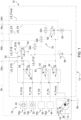
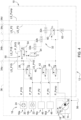
- Fig. 1 shows a schematically illustrated first embodiment of the arrangement according to the invention for operating a load-controlled hydraulic system of an agricultural tractor (not shown).
- the arrangement 10 comprises, as a component of the load-controlled hydraulic system 12, a hydraulic pump 14 whose displacement volume can be adjusted for supplying a large number of hydraulic consumers 16 with pressurized hydraulic fluid.
- the displacement volume of the hydraulic pump 14 is adjusted as a function of a signal transmitted to an actuating device 18 of the hydraulic pump 14.
- load signal pressure LS_Pump This allows a hydraulic supply of the hydraulic consumers 16 corresponding to the actual power requirement.
- the Fig. 1 reproduced hydraulic consumers 16 first and second (primary) hydraulic consumers 16a, 16b, which serve to carry out higher-level hydraulic functions of a hydrostatic vehicle steering 20 and a hydraulic braking system 22, as well as several further (secondary) hydraulic consumers 16c, 16d for carrying out subordinate hydraulic functions that relate to various comfort and work functions of the agricultural tractor, such as a hydraulic axle or cab suspension, a working hydraulic system including the supply of hydraulically operated work units of an additional or attached device attached to the agricultural tractor, but also a hydraulically operated three-point power lift.
- first and second (primary) hydraulic consumers 16a, 16b which serve to carry out higher-level hydraulic functions of a hydrostatic vehicle steering 20 and a hydraulic braking system 22, as well as several further (secondary) hydraulic consumers 16c, 16d for carrying out subordinate hydraulic functions that relate to various comfort and work functions of the agricultural tractor, such as a hydraulic axle or cab suspension, a working hydraulic system including the supply of hydraulically operated work units of an additional or attached device attached to the agricultural tractor, but also
- the first hydraulic consumer 16a or the hydrostatic vehicle steering 20 has a steering orbitrol 24 and a first pressure control valve 26 connected upstream of the steering orbitrol 24, which is actuated as a function of a pressure difference falling across a throttle element 28 against a predetermined restoring force as a function of a load requirement of the hydrostatic vehicle steering 20 represented by a first load signal pressure LS_P1S.
- a hydraulic pressure P_Pump present at a delivery outlet 30 of the hydraulic pump 14 is reduced to a supply pressure P_P1S corresponding to the first load signal pressure LS_P1S, whereas a supply pressure P_P1S required to operate the hydraulic
- the supply pressure P_P1B provided for the braking system 22 is tapped directly at the delivery outlet 30 of the hydraulic pump 14.
- the first load reporting pressure LS_P1S is fed back to a shuttle valve arrangement 32 together with a second load reporting pressure LS_P1B, which represents a load requirement of the hydraulic brake system 22, as well as further load reporting pressures LS_P2, LS_P3 resulting from associated load requirements of the other hydraulic consumers 16c, 16d.
- the displacement volume of the hydraulic pump 14 is specified based on the highest of the load reporting pressures LS_P1S, LS_P1B, LS_P2, LS_P3 reported back by the hydraulic consumers 16.
- the shuttle valve arrangement 32 forms a switching logic consisting of hydraulic shuttle valves 32a, 32b, 32c, which compares the load reporting pressures LS_P1S, LS_P1B, LS_P2, LS_P3 present on the associated load reporting lines 34a, 34b, 34c, 34d in pairs in a cascade manner and forwards or transmits the highest one to the actuating device 18 of the hydraulic pump 14 via a feedback line 36.
- the adjusting device 18 provided for adjusting the displacement volume of the hydraulic pump 14 is a directly pressure-operated actuator 38.
- the adjusting device 18 can also be designed as an electrically operated actuator in accordance with a sensor pressure detection.
- the actuator serves to specifically change a pump swivel angle ⁇ , with the displacement volume of the hydraulic pump 14 increasing as the pump swivel angle ⁇ increases.
- the hydraulic consumers 16 are assigned different supply priorities.
- the hydrostatic vehicle steering 20 and the hydraulic braking system 22 represent higher-level hydraulic functions with the highest supply priority.
- An undersupply leading to possible functional impairments should be avoided as far as possible for these hydraulic consumers 16a, 16b.
- the other hydraulic consumers 16b, 16c are assigned a lower supply priority by means of a priority valve arrangement 40 in view of the fact that they only serve to carry out subordinate hydraulic functions, with the aim of restricting their hydraulic supply if necessary in favor of that of the two hydraulic consumers 16a, 16b with the highest supply priority.
- first and second hydraulic consumers 16a, 16b are connected or can be connected to the delivery outlet 30 of the hydraulic pump 14 directly, while the other hydraulic consumers 16c, 16d are connected or can be connected via intermediate second and third pressure control valves 42, 44, which are part of the priority valve arrangement 40 and serve to provide the associated supply pressures P_P2, P_P3.
- the other hydraulic consumers 16c, 16d are divided into first and second groups 46, 48, whereby the first group 46 can be connected to the delivery outlet 30 of the hydraulic pump 14 via the second pressure control valve 42 and the second group 48 via the third pressure control valve 44.
- the representation of two groups 46, 48 is intended to be merely exemplary. A different number of groups or pressure control valves may also be provided.
- the first load signal pressure LS_P1S is only indirectly reported back to the shuttle valve arrangement 32 via a pressure copying valve 50 provided for fluidic separation, for which purpose the pressure copying valve 50 receives a system pressure generated by the hydraulic pump 14 P_Sys is transmitted to the shuttle valve arrangement 32 by reducing it to a hydraulic pressure LS_P1S' following the first load signaling pressure LS_P1S.
- the first load reporting pressure LS_P1S only serves to control the pressure copying valve 50 without any significant hydraulic flow occurring. There is therefore no direct fluidic connection with the shuttle valve arrangement 32, so that undesirable repercussions on the first load reporting pressure LS_P1S can be reliably ruled out. In the case of the first hydraulic consumer 16a designed as a hydrostatic vehicle steering system 20, this ensures consistent steering behavior independent of the switching state of the shuttle valve arrangement 32.
- Load peaks that occur during operation of the hydrostatic vehicle steering 20 lead to a corresponding increase in the pressure difference falling across the throttle element 28 and cause an increase in the deflection of the first pressure control valve 26 upstream of the steering orbitrol 24 in the direction of a permeable position, which, due to the short control path, leads to a particularly low-reaction and thus "dynamic" adjustment of the hydraulic pressure P_P1S generated to operate the hydrostatic vehicle steering 20.
- the pressure difference is specified for this purpose in the order of 10 to 20 bar.
- the slight but continuous flow of hydraulic fluid through the throttle element 28 in the range of 1 to 5 liters per minute also ensures that a temperature gradient present within the hydraulic circuit of the hydrostatic vehicle steering 20 during a cold start of the agricultural tractor is quickly reduced, jamming in particular the steering orbitrol 24 due to thermal differences or the mechanical stresses caused thereby. This is particularly important at low or wintery outside temperatures.
- the pressure copying valve 50 has a proportional valve 52, to which the system pressure P_Sys generated by the hydraulic pump 14 is applied on the inlet side and the hydraulic pressure LS_P1S' transmitted to the shuttle valve arrangement 32 is applied on the outlet side, wherein the proportional valve 52 is forced into an open position under the effect of the first load reporting pressure LS_P1S against the hydraulic pressure LS_P1S' applied on the outlet side.
- the load reporting pressure LS_P1S' transmitted by the pressure copying valve 50 or the proportional valve 52 to the shuttle valve arrangement 32 then corresponds to the first load reporting pressure LS_P1S except for an offset, which results from a restoring force of a spring element 54 urging the pressure copying valve 50 into a closed position.
- the offset is typically in the range of 1 to 4 bar.
- the system pressure P_Sys is the hydraulic pressure P_Pump present at the delivery outlet 30 of the hydraulic pump 14. This is usually in the order of 200 to 250 bar.
- the hydraulic pressure P_P1S generated by the hydraulic pump 14 to operate the hydrostatic vehicle steering 20 This essentially corresponds to the first Load signal pressure LS_P1S plus the pressure difference across the throttle element 28 and is between 190 and 240 bar.
- the hydraulic pressure LS_P1S' transmitted from the first pressure control valve 26 to the shuttle valve arrangement 32 and thus ultimately the hydraulic pressure P_P1S generated for operating the hydrostatic vehicle steering 20 can be limited by means of a pressure limiting valve 58 opening into a hydraulic reservoir 56 in accordance with a predetermined maximum value P_P1S_max.
- the pressure limiting valve 58 is connected to the outlet of the pressure copying valve 50 or the proportional valve 52 encompassed by it.
- the maximum value P_P1S_max is specified in the range from 170 to 200 bar.
- the hydraulic pressure LS_Pump transmitted to the actuating device 18 of the hydraulic pump 14 can be limited to a specified maximum value LS_Pump_max by means of a pressure control valve 60 on an outlet communicating with the actuating device 18.
- the maximum value LS_Pump_max is specified in such a way that the hydraulic pressure P_Pump generated at the delivery outlet 30 of the hydraulic pump 14 does not exceed a value of 200 and 250 bar. Overpressure-related damage to the hydraulic system or the hydraulic consumers or peripheral components operated with it can thus be reliably prevented.
- the use of the pressure control valve 60 ensures that the hydraulic pressure P_Pump on the outlet side and thus the hydraulic pressure P_Pump generated at the delivery outlet 30 of the hydraulic pump 14 remains constant when the specified maximum value LS_Pump_max is reached in the sense of a stable hydraulic supply.
- a drainage connection in the direction of the hydraulic reservoir 56 is established by means of a further throttle element 62 connected to the outlet of the pressure control valve 60.
- the further throttle element 62 enables a reduction in the hydraulic pressure LS_Pump transmitted to the actuating device 18 of the hydraulic pump 14 in the event that a corresponding reduction in the displacement volume by pivoting the hydraulic pump 14 back is required due to a reduced load requirement reported by the hydraulic consumers 16.
- a further pressure control valve 64 is provided instead of the pressure limiting valve 58, by means of which the hydraulic pressure LS_P1S' transmitted to the shuttle valve arrangement 32 can be limited to a predetermined maximum value LS_P1S'_max at an outlet communicating with the shuttle valve arrangement 32.
- the specification of the maximum value LS_P1S'_max is based on the above-mentioned maximum value P_P1S_max and is approximately 10 to 20 bar lower.
- Fig. 3 or 4 differ in terms of the provision of the system pressure P_Sys. To avoid repetition, reference is made to the relevant description of the variants in question in connection with Fig. 1 or 2 respectively.
Landscapes
- Engineering & Computer Science (AREA)
- Mechanical Engineering (AREA)
- Physics & Mathematics (AREA)
- Fluid Mechanics (AREA)
- General Engineering & Computer Science (AREA)
- Chemical & Material Sciences (AREA)
- Combustion & Propulsion (AREA)
- Transportation (AREA)
- Fluid-Pressure Circuits (AREA)
Abstract
Anordnung (10) zum Betreiben eines lastgesteuerten Hydrauliksystems (12) eines landwirtschaftlichen Traktors, umfassendeine bezüglich ihres Verdrängungsvolumens einstellbare Hydraulikpumpe (14) zur Versorgung mehrerer hydraulischer Verbraucher (16) mit unter Druck stehender Hydraulikflüssigkeit, wobei die Einstellung des Verdrängungsvolumens der Hydraulikpumpe (14) in Abhängigkeit eines an eine Stelleinrichtung (18) der Hydraulikpumpe (14) übermittelten Lastmeldedrucks (LS_Pump) erfolgt. Es sind wenigstens zwei hydraulische Verbraucher (16a, 16b) vorhanden, die entsprechend einer Lastanforderung einen ersten und zweiten Lastmeldedruck (LS_P1S, LS_P1B) an eine Wechselventileinrichtung (32) rückmelden, wobei die Wechselventileinrichtung (32) den jeweils höheren zur Einstellung des Verdrängungsvolumens an die Stelleinrichtung (18) der Hydraulikpumpe (14) übermittelt. Bei einem der hydraulischen Verbraucher (16a) handelt es sich um eine hydrostatische Fahrzeuglenkung (20), wobei deren Lastmeldedruck (LS_P1S) lediglich mittelbar über ein Druckkopierventil (50) an die Wechselventilanordnung (32) rückgemeldet wird.
Description
- Die Erfindung betrifft eine Anordnung zum Betreiben eines lastgesteuerten Hydrauliksystems eines landwirtschaftlichen Traktors, umfassend eine bezüglich ihres Verdrängungsvolumens einstellbare Hydraulikpumpe zur Versorgung hydraulischer Verbraucher mit unter Druck stehender Hydraulikflüssigkeit, wobei die Einstellung des Verdrängungsvolumens der Hydraulikpumpe in Abhängigkeit eines an eine Stelleinrichtung der Hydraulikpumpe übermittelten Lastmeldedrucks erfolgt. Des Weiteren weist die Anordnung einen als hydrostatische Fahrzeuglenkung ausgebildeten ersten hydraulischen Verbraucher mit einem Lenkorbitrol sowie einem dem Lenkorbitrol vorgeschalteten Druckregelventil auf, das in Abhängigkeit einer über ein Drosselelement abfallenden Druckdifferenz entgegen einer vorbestimmten Rückstellkraft in Abhängigkeit einer durch einen ersten Lastmeldedruck repräsentierten Lastanforderung der hydrostatischen Fahrzeuglenkung betätigt wird. Es ist wenigstens ein zweiter hydraulischer Verbraucher vorhanden, der eine durch einen zweiten Lastmeldedruck repräsentierte Lastanforderung an eine Wechselventilanordnung rückmeldet, wobei die Wechselventilanordnung den zweiten Lastmeldedruck mit dem ersten Lastmeldedruck vergleicht sowie den jeweils höheren zur Einstellung des Verdrängungsvolumens der Hydraulikpumpe an die Stelleinrichtung der Hydraulikpumpe übermittelt.
- Ein derart aufgebautes lastgesteuertes Hydrauliksystem findet beispielsweise in landwirtschaftlichen Traktoren der 6R-Serie des Herstellers John Deere Verwendung. Das Hydrauliksystem umfasst hierzu eine aus einem Hydraulikreservoir des landwirtschaftlichen Traktors mit Hydraulikflüssigkeit gespeiste Hydraulikpumpe, deren Verdrängungsvolumen mit dem Betrag eines an einem Steuereingang anliegenden Lastmeldedrucks zunimmt. Auf diese Weise ist eine dem tatsächlichen Leistungsbedarf entsprechende Hydraulikversorgung einer Vielzahl hydraulischer Verbraucher des landwirtschaftlichen Traktors möglich. Hierzu gehören primäre hydraulische Verbraucher, die der Ausführung übergeordneter Hydraulikfunktionen einer hydrostatischen Fahrzeuglenkung sowie einer hydraulischen Bremsanlage dienen, wie auch sekundäre hydraulische Verbraucher zur Ausführung untergeordneter Hydraulikfunktionen, die diverse Komfort- und Arbeitsfunktionen des landwirtschaftlichen Traktors betreffen, wie zum Beispiel einer hydraulischen Achs- oder Kabinenfederung, einer Arbeitshydraulik einschließlich der Versorgung hydraulisch betriebener Arbeitsaggregate eines an dem landwirtschaftlichen Traktor angebrachten Zusatz- oder Anbaugeräts, aber auch eines hydraulisch betätigbaren Dreipunkt-Krafthebers.
- Um für den Fall einer Vielzahl unterschiedlicher hydraulischer Verbraucher eine bedarfsdeckende Versorgung mit hydraulischer Energie sicherzustellen, orientiert sich die Vorgabe des Verdrängungsvolumens am jeweils höchsten der von den hydraulischen Verbrauchern rückgemeldeten Lastmeldedrücke. Zu diesem Zweck ist eine aus hydraulischen Wechselventilen bestehende Schaltlogik vorgesehen, die die an zugehörigen Lastmeldeleitungen anliegenden Lastmeldedrücke paarweise kaskadenartig miteinander vergleicht und den jeweils höchsten an den Steuereingang der Hydraulikpumpe weiterleitet. Je nach Schaltzustand der Wechselventile werden innerhalb der Schaltlogik unterschiedliche Strömungspfade durchlaufen, die der Drainage der Hydraulikflüssigkeit in Richtung eines Hydraulikreservoirs des Hydrauliksystems dienen. Aufgrund der sich daraus ergebenden Variationen des Hydraulikflusses in den Lastmeldeleitungen lassen sich Rückwirkungen auf die an diesen anliegenden Lastmeldedrücke nicht ausschließen. Im Falle eines als hydrostatische Fahrzeuglenkung ausgebildeten hydraulischen Verbrauchers kann dies abhängig vom Schaltzustand der Wechselventilanordnung zu unerwünschten Veränderungen des Lenkverhaltens führen.
- Es ist daher Aufgabe der vorliegenden Erfindung, eine hinsichtlich eines Betriebs einer hydrostatischen Fahrzeuglenkung verbesserte Anordnung der eingangs genannten Art anzugeben.
- Diese Aufgabe wird durch eine Anordnung zum Betreiben eines lastgesteuerten Hydrauliksystems eines landwirtschaftlichen Traktors mit den Merkmalen des Patentanspruchs 1 gelöst.
- Die Anordnung zum Betreiben eines lastgesteuerten Hydrauliksystems eines landwirtschaftlichen Traktors umfasst eine bezüglich ihres Verdrängungsvolumens einstellbare Hydraulikpumpe zur Versorgung hydraulischer Verbraucher mit unter Druck stehender Hydraulikflüssigkeit, wobei die Einstellung des Verdrängungsvolumens der Hydraulikpumpe in Abhängigkeit eines an eine Stelleinrichtung der Hydraulikpumpe übermittelten Lastmeldedrucks erfolgt. Des Weiteren weist die Anordnung einen als hydrostatische Fahrzeuglenkung ausgebildeten ersten hydraulischen Verbraucher mit einem Lenkorbitrol sowie einem dem Lenkorbitrol vorgeschalteten Druckregelventil auf, das in Abhängigkeit einer über ein Drosselelement abfallenden Druckdifferenz entgegen einer vorbestimmten Rückstellkraft in Abhängigkeit einer durch einen ersten Lastmeldedruck repräsentierten Lastanforderung der hydrostatischen Fahrzeuglenkung betätigt wird. Es ist wenigstens ein zweiter hydraulischer Verbraucher vorhanden, der eine durch einen zweiten Lastmeldedruck repräsentierte Lastanforderung an eine Wechselventilanordnung rückmeldet, wobei die Wechselventilanordnung den zweiten Lastmeldedruck mit dem ersten Lastmeldedruck vergleicht sowie den jeweils höheren zur Einstellung des Verdrängungsvolumens der Hydraulikpumpe an die Stelleinrichtung der Hydraulikpumpe übermittelt. Dabei wird der erste Lastmeldedruck lediglich mittelbar über ein zur fluidischen Trennung vorgesehenes Druckkopierventil an die Wechselventilanordnung rückgemeldet, wozu das Druckkopierventil einen mittels der Hydraulikpumpe erzeugten Systemdruck durch Reduzierung auf einen dem ersten Lastmeldedruck folgenden Hydraulikdruck an die Wechselventilanordnung übermittelt.
- Mit anderen Worten dient der erste Lastmeldedruck lediglich der Ansteuerung des Druckkopierventils, ohne dass dabei ein nennenswerter Hydraulikfluss auftritt. Eine unmittelbare fluidische Verbindung mit der Wechselventilanordnung besteht insofern nicht, sodass sich unerwünschte Rückwirkungen auf den ersten Lastmeldedruck verlässlich ausschließen lassen. Für den Fall des als hydrostatische Fahrzeuglenkung ausgebildeten ersten hydraulischen Verbrauchers gewährleistet dies ein vom Schaltzustand der Wechselventilanordnung unabhängiges gleichbleibendes Lenkverhalten.
- Lastspitzen, die beim Betrieb der hydrostatischen Fahrzeuglenkung auftreten, führen zu einer entsprechenden Erhöhung der über das Drosselelement abfallenden Druckdifferenz und verursachen eine Zunahme der Auslenkung des dem Lenkorbitrol vorgeschalteten Druckregelventils in Richtung einer durchlässigen Stellung, was aufgrund der kurzen Regelstrecke zu einer besonders reaktionsarmen und damit "dynamischen" Anpassung eines zum Betrieb der hydrostatischen Fahrzeuglenkung erzeugten Hydraulikdrucks führt. Die Druckdifferenz wird hierzu in der Größenordnung von 10 bis 20 bar vorgegeben.
- Der geringfügige, aber kontinuierliche Fluss von Hydraulikflüssigkeit durch das Drosselelement im Bereich von 1 bis 5 Litern pro Minute gewährleistet zudem, dass ein innerhalb des Hydraulikreislaufs der hydrostatischen Fahrzeuglenkung bei einem Kaltstart des landwirtschaftlichen Traktors vorhandenes Temperaturgefälle rasch abgebaut wird, ein Verklemmen insbesondere des Lenkorbitrols aufgrund thermischer Unterschiede bzw. dadurch verursachter mechanischer Spannungen nicht auftritt. Dies ist vor allem bei niedrigen bzw. winterlichen Außentemperaturen von Belang.
- Bei der zur Einstellung des Verdrängungsvolumens der Hydraulikpumpe vorgesehenen Stelleinrichtung kann es sich entweder um einen unmittelbar druckbetätigten Aktuator oder aber um einen nach Maßgabe einer sensorischen Druckerfassung elektrisch betätigten Aktuator handeln. In beiden Fällen dient der Aktuator der gezielten Veränderung eines Pumpenschwenkwinkels, wobei das Verdrängungsvolumen der Hydraulikpumpe mit größer werdendem Pumpenschwenkwinkel zunimmt.
- Da zum Betrieb der hydraulischen Verbraucher ein und dieselbe Hydraulikpumpe dient, deren Förderkapazität jedoch begrenzt ist, sind den hydraulischen Verbrauchern in der Regel unterschiedliche Versorgungsprioritäten zugeordnet. So stellen hydraulische Brems- und Lenksysteme übergeordnete Hydraulikfunktionen mit der höchsten Versorgungspriorität dar. Eine zu möglichen Funktionsbeeinträchtigungen führende Unterversorgung ist bei diesen hydraulischen Verbrauchern tunlichst auszuschließen. Dementsprechend wird hydraulischen Verbrauchern, die der Ausführung untergeordneter Hydraulikfunktionen dienen, mittels einer Prioritätsventilanordnung eine geringere Versorgungspriorität zugeordnet, mit dem Ziel, deren hydraulische Versorgung bei Bedarf zugunsten derjenigen der hydraulischen Verbraucher der höchsten Versorgungspriorität einzuschränken. Zu den untergeordneten Hydraulikfunktionen zählen insbesondere solche, die den Betrieb von Komfort- und Arbeitsfunktionen des landwirtschaftlichen Traktors, wie zum Beispiel einer hydraulischen Achs- oder Kabinenfederung, einer Arbeitshydraulik einschließlich der Versorgung hydraulisch betriebener Arbeitsaggregate eines an dem landwirtschaftlichen Traktor angebrachten Zusatz- oder Anbaugeräts, aber auch eines hydraulisch betätigbaren Dreipunkt-Krafthebers betreffen.
- Vorteilhafte Ausführungen der erfindungsgemäßen Anordnung gehen aus den Unteransprüchen hervor.
- Vorzugsweise weist das Druckkopierventil ein Proportionalventil auf, an dem einlassseitig der mittels der Hydraulikpumpe erzeugte Systemdruck und auslassseitig der an die Wechselventilanordnung übermittelte Hydraulikdruck anliegt, wobei das Proportionalventil unter der Wirkung des ersten Lastmeldedrucks entgegen dem auslassseitig anliegenden Hydraulikdruck in eine geöffnete Stellung gedrängt wird. Letzteres erfolgt bis zur Einstellung eines Druckgleichgewichts zwischen Einlass und Auslass des Proportionalventils, wobei der von dem Drucckopierventil bzw. dem Proportionalventil an die Wechselventilanordnung übermittelte Lastmeldedruck dann bis auf einen Offset mit dem ersten Lastmeldedruck übereinstimmt, der sich aus einer das Druckkopierventil in eine geschlossene Stellung drängenden Rückstellkraft eines Federelements ergibt. Der Offset liegt typischerweise in der Größenordnung von 1 bis 4 bar.
- Bezüglich der Bereitstellung des Systemdrucks sind verschiedene Varianten denkbar. Zum einen ist es möglich, dass es sich bei dem Systemdruck um einen an einem Förderausgang der Hydraulikpumpe anliegenden Hydraulikdruck handelt. Dieser liegt üblicherweise in der Größenordnung von 200 bis 250 bar. Zum anderen kann es sich auch um einen von der Hydraulikpumpe zum Betrieb der hydrostatischen Fahrzeuglenkung erzeugten Hydraulikdruck handeln. Dieser entspricht im Wesentlichen dem ersten Lastmeldedruck zuzüglich der über das Drosselelement abfallenden Druckdifferenz und beträgt zwischen 190 und 240 bar. Welche der beiden Varianten gewählt wird, hängt letztlich von dem im Einzelfall zur Verfügung stehenden Bauraum zur Verlegung der entsprechenden Zuleitungen ab.
- Des Weiteren besteht die Möglichkeit, dass der von dem Druckregelventil an die Wechselventilanordnung übermittelte Hydraulikdruck und damit letztlich der zum Betrieb der hydrostatischen Fahrzeuglenkung erzeugte Hydraulikdruck mittels eines in ein Hydraulikreservoir mündenden Druckbegrenzungsventils entsprechend einem vorgegebenen Höchstwert begrenzbar ist. Das Druckbegrenzungsventil ist insbesondere am Auslass des Drucckopierventils bzw. des von diesem umfassten Proportionalventils angeschlossen. Der Höchstwert wird im Bereich von 170 bis 200 bar vorgegeben.
- Um die beim Ansprechen des Druckbegrenzungsventils in Richtung des Hydraulikreservoirs auftretenden Hydraulikverluste zu vermeiden, ist es andererseits auch vorstellbar, dass anstelle eines Druckbegrenzungsventils ein Druckregelventil vorgesehen ist, mittels dessen der an die Wechselventilanordnung übermittelte Hydraulikdruck an einem mit der Wechselventilanordnung kommunizierenden Auslass auf einen vorgegebenen Höchstwert begrenzbar ist. Die Vorgabe des Höchstwerts orientiert sich an dem vorstehend erwähnten Höchstwert.
- Ferner kann vorgesehen sein, dass der an die Stelleinrichtung der Hydraulikpumpe übermittelte Hydraulikdruck mittels eines weiteren Druckregelventils an einem mit der Stelleinrichtung kommunizierenden Auslass auf einen vorgegebenen Höchstwert begrenzbar ist. Die Vorgabe des Höchstwerts erfolgt derart, dass der am Förderausgang der Hydraulikpumpe erzeugte Hydraulikdruck einen Wert von 200 und 250 bar nicht überschreitet. Überdruckbedingten Schäden des Hydrauliksystems oder der damit betriebenen hydraulischen Verbraucher bzw. peripheren Komponenten kann so zuverlässig vorgebeugt werden. Die Verwendung eines Druckregelventils stellt sicher, dass der auslassseitige und damit der am Förderausgang der Hydraulikpumpe erzeugte Hydraulikdruck bei Erreichen des vorgegebenen Höchstwerts im Sinne einer stabilen Hydraulikversorgung konstant bleibt.
- Bevorzugt ist mittels eines mit dem Auslass des weiteren Druckregelventils verbundenen weiteren Drosselelements eine Drainageverbindung in Richtung eines Hydraulikreservoirs hergestellt. Das weitere Drosselelement ermöglicht einen Abbau des an die Stelleinrichtung der Hydraulikpumpe übermittelten Hydraulikdrucks, für den Fall, dass aufgrund einer seitens der hydraulischen Verbraucher rückgemeldeten reduzierten Lastanforderung eine entsprechende Verringerung des Verdrängungsvolumens durch Zurückschwenken der Hydraulikpumpe erforderlich ist.
- Die erfindungsgemäße Anordnung wird im Folgenden anhand der beigefügten Zeichnungen näher erläutert. Hierbei bezeichnen übereinstimmende Bezugszeichen identische oder bezüglich ihrer Funktion vergleichbare Komponenten. Es zeigen:
- Fig. 1
- ein schematisch dargestelltes erstes Ausführungsbeispiel der erfindungsgemäßen Anordnung zum Betreiben eines lastgesteuerten Hydrauliksystems eines landwirtschaftlichen Traktors,
- Fig. 2
- eine Variante des in
Fig. 1 wiedergegebenen ersten Ausführungsbeispiels der erfindungsgemäßen Anordnung, - Fig. 3
- ein schematisch dargestelltes zweites Ausführungsbeispiel der erfindungsgemäßen Anordnung zum Betreiben eines lastgesteuerten Hydrauliksystems eines landwirtschaftlichen Traktors, und
- Fig. 4
- eine Variante des in
Fig. 3 wiedergegebenen zweiten Ausführungsbeispiels der erfindungsgemäßen Anordnung. -
Fig. 1 zeigt ein schematisch dargestelltes erstes Ausführungsbeispiel der erfindungsgemäßen Anordnung zum Betreiben eines lastgesteuerten Hydrauliksystems eines nicht wiedergegebenen landwirtschaftlichen Traktors. - Die Anordnung 10 umfasst als Bestandteil des lastgesteuerten Hydrauliksystems 12 eine bezüglich ihres Verdrängungsvolumens einstellbare Hydraulikpumpe 14 zur Versorgung einer Vielzahl hydraulischer Verbraucher 16 mit unter Druck stehender Hydraulikflüssigkeit. Die Einstellung des Verdrängungsvolumens der Hydraulikpumpe 14 erfolgt in Abhängigkeit eines an eine Stelleinrichtung 18 der Hydraulikpumpe 14 übermittelten Lastmeldedrucks LS_Pump. Dies erlaubt eine dem tatsächlichen Leistungsbedarf entsprechende Hydraulikversorgung der hydraulischen Verbraucher 16.
- Beispielsgemäß gehören zu den in
Fig. 1 wiedergegebenen hydraulischen Verbrauchern 16 erste und zweite (primäre) hydraulische Verbraucher 16a, 16b, die der Ausführung übergeordneter Hydraulikfunktionen einer hydrostatischen Fahrzeuglenkung 20 sowie einer hydraulischen Bremsanlage 22 dienen, wie auch mehrere weitere (sekundäre) hydraulische Verbraucher 16c, 16d zur Ausführung untergeordneter Hydraulikfunktionen, die diverse Komfort- und Arbeitsfunktionen des landwirtschaftlichen Traktors betreffen, wie zum Beispiel einer hydraulischen Achs- oder Kabinenfederung, einer Arbeitshydraulik einschließlich der Versorgung hydraulisch betriebener Arbeitsaggregate eines an dem landwirtschaftlichen Traktor angebrachten Zusatz- oder Anbaugeräts, aber auch eines hydraulisch betätigbaren Dreipunkt-Krafthebers. - Hierbei weist der erste hydraulische Verbraucher 16a bzw. die hydrostatische Fahrzeuglenkung 20 ein Lenkorbitrol 24 sowie ein dem Lenkorbitrol 24 vorgeschaltetes erstes Druckregelventil 26 auf, das in Abhängigkeit einer über ein Drosselelement 28 abfallenden Druckdifferenz entgegen einer vorbestimmten Rückstellkraft in Abhängigkeit einer durch einen ersten Lastmeldedruck LS_P1S repräsentierten Lastanforderung der hydrostatischen Fahrzeuglenkung 20 betätigt wird.
- Auf diese Weise wird ein an einem Förderausgang 30 der Hydraulikpumpe 14 anliegender Hydraulikdruck P_Pump auf einen dem ersten Lastmeldedruck LS_P1S entsprechenden Versorgungsdruck P_P1S reduziert, wohingegen ein zum Betrieb der hydraulischen Bremsanlage 22 vorgesehener Versorgungsdruck P_P1B am Förderausgang 30 der Hydraulikpumpe 14 unmittelbar abgegriffen wird.
- Der erste Lastmeldedruck LS_P1S wird gemeinsam mit einem zweiten Lastmeldedruck LS_P1B, der eine Lastanforderung der hydraulischen Bremsanlage 22 repräsentiert, sowie sich aufgrund zugehöriger Lastanforderungen der weiteren hydraulischen Verbraucher 16c, 16d ergebender weiterer Lastmeldedrücke LS_P2, LS_P3 an eine Wechselventilanordnung 32 rückgemeldet.
- Um eine bedarfsdeckende Versorgung mit hydraulischer Energie sicherzustellen, orientiert sich die Vorgabe des Verdrängungsvolumens der Hydraulikpumpe 14 am jeweils höchsten der von den hydraulischen Verbrauchern 16 rückgemeldeten Lastmeldedrücke LS_P1S, LS_P1B, LS_P2, LS_P3. Zu diesem Zweck bildet die Wechselventilanordnung 32 eine aus hydraulischen Wechselventilen 32a, 32b, 32c bestehende Schaltlogik, die die an zugehörigen Lastmeldeleitungen 34a, 34b, 34c, 34d anliegenden Lastmeldedrücke LS_P1S, LS_P1B, LS_P2, LS_P3 paarweise kaskadenartig miteinander vergleicht und den jeweils höchsten über eine Rückmeldeleitung 36 an die Stelleinrichtung 18 der Hydraulikpumpe 14 weiterleitet bzw. an diese übermittelt.
- Vorliegend handelt es sich bei der zur Einstellung des Verdrängungsvolumens der Hydraulikpumpe 14 vorgesehenen Stelleinrichtung 18 um einen unmittelbar druckbetätigten Aktuator 38. Abweichend davon kann die Stelleinrichtung 18 jedoch auch als nach Maßgabe einer sensorischen Druckerfassung elektrisch betätigter Aktuator ausgebildet sein. In beiden Fällen dient der Aktuator der gezielten Veränderung eines Pumpenschwenkwinkels α, wobei das Verdrängungsvolumen der Hydraulikpumpe 14 mit größer werdendem Pumpenschwenkwinkel α zunimmt.
- Da zum Betrieb der hydraulischen Verbraucher 16 ein und dieselbe Hydraulikpumpe 14 Verwendung findet, deren Förderkapazität jedoch begrenzt ist, sind den hydraulischen Verbrauchern 16 unterschiedliche Versorgungsprioritäten zugeordnet. Hierbei stellen die hydrostatische Fahrzeuglenkung 20 wie auch die hydraulische Bremsanlage 22 übergeordnete Hydraulikfunktionen mit der höchsten Versorgungspriorität dar. Eine zu möglichen Funktionsbeeinträchtigungen führende Unterversorgung ist bei diesen hydraulischen Verbrauchern 16a, 16b tunlichst auszuschließen. Dementsprechend wird den weiteren hydraulischen Verbrauchern 16b, 16c angesichts des Umstands, dass diese der Ausführung lediglich untergeordneter Hydraulikfunktionen dienen, mittels einer Prioritätsventilanordnung 40 eine geringere Versorgungspriorität zugeordnet, mit dem Ziel, deren hydraulische Versorgung bei Bedarf zugunsten derjenigen der beiden hydraulischen Verbraucher 16a, 16b der höchsten Versorgungspriorität einzuschränken.
- Hierbei sind die ersten und zweiten hydraulischen Verbraucher 16a, 16b unmittelbar, die weiteren hydraulischen Verbraucher 16c, 16d hingegen über zwischengeschaltete zweite und dritte Druckregelventile 42, 44, die Bestandteil der Prioritätsventilanordnung 40 sind und der Bereitstellung zugehöriger Versorgungsdrücke P_P2, P_P3 dienen, mit dem Förderausgang 30 der Hydraulikpumpe 14 verbunden bzw. verbindbar. Die weiteren hydraulischen Verbraucher 16c, 16d sind in erste bzw. zweite Gruppen 46, 48 unterteilt, wobei sich die erste Gruppe 46 über das zweite Druckregelventil 42 und die zweite Gruppe 48 über das dritte Druckregelventil 44 mit dem Förderausgang 30 der Hydraulikpumpe 14 verbinden lässt. Die Darstellung zweier Gruppen 46, 48 soll dabei lediglich beispielhaften Charakter haben, es kann auch eine davon abweichende Anzahl an Gruppen bzw. Druckregelventilen vorgesehen sein.
- Sind entsprechend dem in
Fig. 1 wiedergegebenen Ausführungsbeispiel der Anordnung 10 mehrere Druckregelventile 42, 44 vorhanden, so werden diese zur Reduzierung des Leistungsbedarfs entsprechend der Förderkapazität der Hydraulikpumpe 14 in einer vorgegebenen Reihenfolge, nämlich bei sukzessivem Abfall der Differenz zwischen dem am Förderausgang 30 der Hydraulikpumpe 14 anliegenden Hydraulikdruck P_Pump und dem an die Stelleinrichtung 18 der Hydraulikpumpe 14 übermittelten Hydraulikdruck LS_Pump unter einen ersten bzw. zweiten Schwellenwert P_P2_min, P_P3_min (P_P2_min > P_P3_min) in ihre geschlossene Stellung verbracht. - Hierdurch lässt sich eine weitere Unterteilung bzw. Abstufung der Versorgungsprioritäten der weiteren hydraulischen Verbraucher 16c, 16d verwirklichen, sodass der Betrieb bestimmter Hydraulikfunktionen so weit wie möglich aufrechterhalten werden kann. So kann bezüglich der Reihenfolge der Drosselung des durch die beiden Druckregelventile 42, 44 hindurchtretenden Hydraulikvolumenstroms vorgesehen sein, dass zunächst Komfortfunktionen und erst danach gegebenenfalls Arbeitsfunktionen einschließlich einer hydraulischen Getriebesteuerung eines von einem Antriebsstrang des landwirtschaftlichen Traktors umfassten Fahr- und/oder Zapfwellengetriebes betroffen sind.
- Wie weiterhin in
Fig. 1 zu erkennen ist, wird der erste Lastmeldedruck LS_P1S lediglich mittelbar über ein zur fluidischen Trennung vorgesehenes Druckkopierventil 50 an die Wechselventilanordnung 32 rückgemeldet, wozu das Druckkopierventil 50 einen mittels der Hydraulikpumpe 14 erzeugten Systemdruck P_Sys durch Reduzierung auf einen dem ersten Lastmeldedruck LS_P1S folgenden Hydraulikdruck LS_P1S' an die Wechselventilanordnung 32 übermittelt. - Mit anderen Worten dient der erste Lastmeldedruck LS_P1S lediglich der Ansteuerung des Druckkopierventils 50, ohne dass dabei ein nennenswerter Hydraulikfluss auftritt. Eine unmittelbare fluidische Verbindung mit der Wechselventilanordnung 32 besteht insofern nicht, sodass sich unerwünschte Rückwirkungen auf den ersten Lastmeldedruck LS_P1S verlässlich ausschließen lassen. Für den Fall des als hydrostatische Fahrzeuglenkung 20 ausgebildeten ersten hydraulischen Verbrauchers 16a gewährleistet dies ein vom Schaltzustand der Wechselventilanordnung 32 unabhängiges gleichbleibendes Lenkverhalten.
- Lastspitzen, die beim Betrieb der hydrostatischen Fahrzeuglenkung 20 auftreten, führen zu einer entsprechenden Erhöhung der über das Drosselelement 28 abfallenden Druckdifferenz und verursachen eine Zunahme der Auslenkung des dem Lenkorbitrol 24 vorgeschalteten ersten Druckregelventils 26 in Richtung einer durchlässigen Stellung, was aufgrund der kurzen Regelstrecke zu einer besonders reaktionsarmen und damit "dynamischen" Anpassung des zum Betrieb der hydrostatischen Fahrzeuglenkung 20 erzeugten Hydraulikdrucks P_P1S führt. Die Druckdifferenz wird hierzu in der Größenordnung von 10 bis 20 bar vorgegeben.
- Der geringfügige, aber kontinuierliche Fluss von Hydraulikflüssigkeit durch das Drosselelement 28 im Bereich von 1 bis 5 Litern pro Minute gewährleistet zudem, dass ein innerhalb des Hydraulikreislaufs der hydrostatischen Fahrzeuglenkung 20 bei einem Kaltstart des landwirtschaftlichen Traktors vorhandenes Temperaturgefälle rasch abgebaut wird, ein Verklemmen insbesondere des Lenkorbitrols 24 aufgrund thermischer Unterschiede bzw. dadurch verursachter mechanischer Spannungen nicht auftritt. Dies ist vor allem bei niedrigen bzw. winterlichen Außentemperaturen von Belang.
- Gemäß
Fig. 1 weist das Druckkopierventil 50 ein Proportionalventil 52 auf, an dem einlassseitig der mittels der Hydraulikpumpe 14 erzeugte Systemdruck P_Sys und auslassseitig der an die Wechselventilanordnung 32 übermittelte Hydraulikdruck LS_P1S' anliegt, wobei das Proportionalventil 52 unter der Wirkung des ersten Lastmeldedrucks LS_P1S entgegen dem auslassseitig anliegenden Hydraulikdruck LS_P1S' in eine geöffnete Stellung gedrängt wird. Letzteres erfolgt bis zur Einstellung eines Druckgleichgewichts zwischen Einlass und Auslass des Proportionalventils 52, wobei der von dem Druckkopierventil 50 bzw. dem Proportionalventil 52 an die Wechselventilanordnung 32 übermittelte Lastmeldedruck LS_P1S' dann bis auf einen Offset mit dem ersten Lastmeldedruck LS_P1S übereinstimmt, der sich aus einer das Druckkopierventil 50 in eine geschlossene Stellung drängenden Rückstellkraft eines Federelements 54 ergibt. Der Offset liegt typischerweise in der Größenordnung von 1 bis 4 bar. - Bezüglich der Bereitstellung des Systemdrucks P_Sys sind verschiedene Varianten denkbar. Zum einen ist es gemäß
Fig. 1 möglich, dass es sich bei dem Systemdruck P_Sys um den am Förderausgang 30 der Hydraulikpumpe 14 anliegenden Hydraulikdruck P_Pump handelt. Dieser liegt üblicherweise in der Größenordnung von 200 bis 250 bar. Zum anderen kann es sich gemäßFig. 2 auch um den von der Hydraulikpumpe 14 zum Betrieb der hydrostatischen Fahrzeuglenkung 20 erzeugten Hydraulikdruck P_P1S handeln. Dieser entspricht im Wesentlichen dem ersten Lastmeldedruck LS_P1S zuzüglich der über das Drosselelement 28 abfallenden Druckdifferenz und beträgt zwischen 190 und 240 bar. - Im Falle des in
Fig. 1 bzw. 2 wiedergegebenen ersten Ausführungsbeispiels ist der von dem ersten Druckregelventil 26 an die Wechselventilanordnung 32 übermittelte Hydraulikdruck LS_P1S' und damit letztlich der zum Betrieb der hydrostatischen Fahrzeuglenkung 20 erzeugte Hydraulikdruck P_P1S mittels eines in ein Hydraulikreservoir 56 mündenden Druckbegrenzungsventils 58 entsprechend einem vorgegebenen Höchstwert P_P1S_max begrenzbar. Das Druckbegrenzungsventil 58 ist am Auslass des Druckkopierventils 50 bzw. des von diesem umfassten Proportionalventils 52 angeschlossen. Der Höchstwert P_P1S_max wird im Bereich von 170 bis 200 bar vorgegeben. - Daneben ist der an die Stelleinrichtung 18 der Hydraulikpumpe 14 übermittelte Hydraulikdruck LS_Pump mittels eines Druckregelventils 60 an einem mit der Stelleinrichtung 18 kommunizierenden Auslass auf einen vorgegebenen Höchstwert LS_Pump_max begrenzbar. Die Vorgabe des Höchstwerts LS_Pump_max erfolgt derart, dass der am Förderausgang 30 der Hydraulikpumpe 14 erzeugte Hydraulikdruck P_Pump einen Wert von 200 und 250 bar nicht überschreitet. Überdruckbedingten Schäden des Hydrauliksystems oder der damit betriebenen hydraulischen Verbraucher bzw. peripheren Komponenten kann so zuverlässig vorgebeugt werden. Die Verwendung des Druckregelventils 60 stellt sicher, dass der auslassseitige und damit der am Förderausgang 30 der Hydraulikpumpe 14 erzeugte Hydraulikdruck P_Pump bei Erreichen des vorgegebenen Höchstwerts LS_Pump_max im Sinne einer stabilen Hydraulikversorgung konstant bleibt.
- Mittels eines mit dem Auslass des Druckregelventils 60 verbundenen weiteren Drosselelements 62 ist eine Drainageverbindung in Richtung des Hydraulikreservoirs 56 hergestellt. Das weitere Drosselelement 62 ermöglicht einen Abbau des an die Stelleinrichtung 18 der Hydraulikpumpe 14 übermittelten Hydraulikdrucks LS_Pump, für den Fall, dass aufgrund einer seitens der hydraulischen Verbraucher 16 rückgemeldeten reduzierten Lastanforderung eine entsprechende Verringerung des Verdrängungsvolumens durch Zurückschwenken der Hydraulikpumpe 14 erforderlich ist.
- Sollen die beim Ansprechen des Druckbegrenzungsventils 58 in Richtung des Hydraulikreservoirs 56 auftretenden Hydraulikverluste vermieden werden, so ist im Falle eines in
Fig. 3 bzw. 4 wiedergegebenen zweiten Ausführungsbeispiels der erfindungsgemäßen Anordnung 10 anstelle des Druckbegrenzungsventils 58 ein weiteres Druckregelventil 64 vorgesehen, mittels dessen der an die Wechselventilanordnung 32 übermittelte Hydraulikdruck LS_P1S' an einem mit der Wechselventilanordnung 32 kommunizierenden Auslass auf einen vorgegebenen Höchstwert LS_P1S'_max begrenzbar ist. Die Vorgabe des Höchstwerts LS_P1S'_max orientiert sich an dem vorstehend erwähnten Höchstwert P_P1S_max und liegt in etwa 10 bis 20 bar darunter. -
Fig. 3 bzw. 4 unterscheiden sich wiederum hinsichtlich der Bereitstellung des Systemdrucks P_Sys. Zur Vermeidung von Wiederholungen sei insofern auf die einschlägige Beschreibung der betreffenden Varianten in Zusammenhang mitFig. 1 bzw. 2 hingewiesen.
Claims (8)
- Anordnung zum Betreiben eines lastgesteuerten Hydrauliksystems eines landwirtschaftlichen Traktors, umfassend eine bezüglich ihres Verdrängungsvolumens einstellbare Hydraulikpumpe (14) zur Versorgung hydraulischer Verbraucher (16) mit unter Druck stehender Hydraulikflüssigkeit, wobei die Einstellung des Verdrängungsvolumens der Hydraulikpumpe (14) in Abhängigkeit eines an eine Stelleinrichtung (18) der Hydraulikpumpe (14) übermittelten Lastmeldedrucks (LS_Pump) erfolgt,
einen als hydrostatische Fahrzeuglenkung (20) ausgebildeten ersten hydraulischen Verbraucher (16a) mit einem Lenkorbitrol (24) sowie einem dem Lenkorbitrol (24) vorgeschalteten Druckregelventil (26), das in Abhängigkeit einer über ein Drosselelement (28) abfallenden Druckdifferenz entgegen einer vorbestimmten Rückstellkraft in Abhängigkeit einer durch einen ersten Lastmeldedruck (LS_P1S) repräsentierten Lastanforderung der hydrostatischen Fahrzeuglenkung (20) betätigt wird, und wenigstens einen zweiten hydraulischen Verbraucher (16b), der eine durch einen zweiten Lastmeldedruck (LS_P1B) repräsentierte Lastanforderung an eine Wechselventilanordnung (32) rückmeldet, wobei die Wechselventilanordnung (32) den zweiten Lastmeldedruck (LS_P1B) mit dem ersten Lastmeldedruck (LS_P1S) vergleicht sowie den jeweils höheren zur Einstellung des Verdrängungsvolumens der Hydraulikpumpe (14) an die Stelleinrichtung (18) der Hydraulikpumpe (14) übermittelt,
dadurch gekennzeichnet, dass der erste Lastmeldedruck (LS_P1S) lediglich mittelbar über ein zur fluidischen Trennung vorgesehenes Druckkopierventil (50) an die Wechselventilanordnung (32) rückgemeldet wird, wozu das Druckkopierventil (50) einen mittels der Hydraulikpumpe (14) erzeugten Systemdruck (P_Sys) durch Reduzierung auf einen dem ersten Lastmeldedruck (LS_P1S) folgenden Hydraulikdruck (LS_P1S') an die Wechselventilanordnung (32) übermittelt. - Anordnung nach Anspruch 1, dadurch gekennzeichnet, dass das Druckkopierventil (50) ein Proportionalventil (52) aufweist, an dem einlassseitig der mittels der Hydraulikpumpe (14) erzeugte Systemdruck (P_Sys) und auslassseitig der an die Wechselventilanordnung (32) zu übermittelte Hydraulikdruck (LS_P1S') anliegt, wobei das Proportionalventil (52) unter der Wirkung des ersten Lastmeldedrucks (LS_P1S) entgegen dem auslassseitig anliegenden Hydraulikdruck (LS_P1S') in eine geöffnete Stellung gedrängt wird.
- Anordnung nach Anspruch 1 oder 2, dadurch gekennzeichnet, dass es sich bei dem Systemdruck (P_Sys) um einen an einem Förderausgang (30) der Hydraulikpumpe (40) anliegenden Hydraulikdruck (P_Pump) handelt.
- Anordnung nach Anspruch 1 oder 2, dadurch gekennzeichnet, dass es sich bei dem Systemdruck (P_Sys) um einen von der Hydraulikpumpe (14) zum Betrieb der hydrostatischen Fahrzeuglenkung (20) erzeugten Hydraulikdruck (P_1PS) handelt.
- Anordnung nach einem der vorhergehenden Ansprüche,
dadurch gekennzeichnet, dass der von dem Druckregelventil (26) an die Wechselventilanordnung (32) übermittelte Hydraulikdruck (LS_P1S') mittels eines in ein Hydraulikreservoir (56) mündenden Druckbegrenzungsventils (58) entsprechend einem vorgegebenen Höchstwert (P_P1S_max) begrenzbar ist. - Anordnung nach einem der vorhergehenden Ansprüche,
dadurch gekennzeichnet, dass ein Druckbegrenzungsventil (60) vorgesehen ist, mittels dessen der an die Wechselventilanordnung (32) übermittelte Hydraulikdruck (LS_P1S') an einem mit der Wechselventilanordnung (32) kommunizierenden Auslass auf einen vorgegebenen Höchstwert (LS_Pump_max) begrenzbar ist. - Anordnung nach einem der vorhergehenden Ansprüche,
dadurch gekennzeichnet, dass der an die Stelleinrichtung (18) der Hydraulikpumpe (14) übermittelte Hydraulikdruck (P_Pump) mittels eines weiteren Druckbegrenzungsventils (64) an einem mit der Stelleinrichtung (18) kommunizierenden Auslass auf einen vorgegebenen Höchstwert (LS_P1S'_max) begrenzbar ist. - Anordnung nach Anspruch 7, dadurch gekennzeichnet, dass mittels eines mit dem Auslass des weiteren Druckbegrenzungsventils (64) verbundenen weiteren Drosselelements (62) eine Drainageverbindung in Richtung eines Hydraulikreservoirs (56) hergestellt ist.
Applications Claiming Priority (2)
| Application Number | Priority Date | Filing Date | Title |
|---|---|---|---|
| DE102023117329 | 2023-06-30 | ||
| DE102023117494.0A DE102023117494A1 (de) | 2023-06-30 | 2023-07-03 | Anordnung zum Betreiben eines lastgesteuerten Hydrauliksystems eines landwirtschaftlichen Traktors |
Publications (1)
| Publication Number | Publication Date |
|---|---|
| EP4484762A1 true EP4484762A1 (de) | 2025-01-01 |
Family
ID=91580854
Family Applications (1)
| Application Number | Title | Priority Date | Filing Date |
|---|---|---|---|
| EP24182147.9A Pending EP4484762A1 (de) | 2023-06-30 | 2024-06-14 | Anordnung zum betreiben eines lastgesteuerten hydrauliksystems eines landwirtschaftlichen traktors |
Country Status (2)
| Country | Link |
|---|---|
| US (1) | US20250003430A1 (de) |
| EP (1) | EP4484762A1 (de) |
Families Citing this family (1)
| Publication number | Priority date | Publication date | Assignee | Title |
|---|---|---|---|---|
| US12434760B2 (en) * | 2023-04-27 | 2025-10-07 | Deere & Company | Apparatus for operating a load-controlled hydraulic supply of an agricultural tractor |
Citations (3)
| Publication number | Priority date | Publication date | Assignee | Title |
|---|---|---|---|---|
| US4463558A (en) * | 1983-08-12 | 1984-08-07 | Deere & Company | Load sensing hydraulic system |
| US20080047423A1 (en) * | 2006-08-25 | 2008-02-28 | Joshua Dean Graeve | Fluid system with signal-mimicking device and associated method |
| US20180222522A1 (en) * | 2017-02-09 | 2018-08-09 | Deere & Company | Dual Margin Priority Circuit For Increased Steering Capacity |
-
2024
- 2024-05-28 US US18/675,460 patent/US20250003430A1/en active Pending
- 2024-06-14 EP EP24182147.9A patent/EP4484762A1/de active Pending
Patent Citations (3)
| Publication number | Priority date | Publication date | Assignee | Title |
|---|---|---|---|---|
| US4463558A (en) * | 1983-08-12 | 1984-08-07 | Deere & Company | Load sensing hydraulic system |
| US20080047423A1 (en) * | 2006-08-25 | 2008-02-28 | Joshua Dean Graeve | Fluid system with signal-mimicking device and associated method |
| US20180222522A1 (en) * | 2017-02-09 | 2018-08-09 | Deere & Company | Dual Margin Priority Circuit For Increased Steering Capacity |
Also Published As
| Publication number | Publication date |
|---|---|
| US20250003430A1 (en) | 2025-01-02 |
Similar Documents
| Publication | Publication Date | Title |
|---|---|---|
| EP3567167B1 (de) | Hydraulische steueranordnung für eine anordnung mobiler arbeitsmaschinen und anordnung mobiler arbeitsmaschinen | |
| EP1642035A1 (de) | Hydraulisches system | |
| DE4108915C2 (de) | Hydraulische Einrichtung zur Druckmittelversorgung eines bevorrechtigten Primärlastkreises | |
| EP3058236B1 (de) | Steuervorrichtung | |
| DE102018125053B4 (de) | Hydraulische Lenkanordnung | |
| DE4235707B4 (de) | Hydrostatisches Antriebssystem | |
| EP3625457B1 (de) | Steuervorrichtung zum versorgen mindestens eines hydraulischen verbrauchers mit fluid | |
| EP3398418A1 (de) | Hydrauliksystem einer land- oder bauwirtschaftlich nutzbaren arbeitsmaschine | |
| DE102021117185A1 (de) | Vorsteuerneutralisierungssystem | |
| DE102021117193A1 (de) | Vorsteuerneutralisierungssystem | |
| DE102006019804B4 (de) | Hydraulische Lenkung | |
| DE19931143B4 (de) | Hydraulische Lenkeinrichtung | |
| DE102007051525B4 (de) | Hydraulisches Versorgungssystem mit einer Verstellpumpeneinrichtung | |
| WO2016091528A1 (de) | Hydraulische ventilanordnung, hydraulischer ventilblock mit einer derartigen ventilanordnung, und hydraulischer antrieb mit einem derartigen ventilblock | |
| EP4455488A1 (de) | Vorrichtung zum betreiben einer lastgesteuerten hydraulikver-sorgung eines landwirtschaftlichen traktors | |
| EP2157320A1 (de) | Hydrauliksteuerung für einen Hydromotor | |
| DE19548943B4 (de) | Ventilanordnung | |
| DE4210252C1 (de) | ||
| DE102023117494A1 (de) | Anordnung zum Betreiben eines lastgesteuerten Hydrauliksystems eines landwirtschaftlichen Traktors | |
| EP4275465B1 (de) | Hydraulische verstellvorrichtung | |
| WO2003087585A1 (de) | Hydraulische steueranordnung in load-sensing technik | |
| EP1954949B1 (de) | Hydraulische steuervorrichtung | |
| DE102016105159B4 (de) | Hydrauliksystem eines land- oder bauwirtschaftlich nutzbaren Fahrzeugs | |
| EP2613059A2 (de) | Vorrichtung zur Ansteuerung eines fluidbetätigten Aktuators bei einer Arbeitsgerätschaft | |
| DE102023205767B3 (de) | Hydraulikventilverband und Mobilhydraulik |
Legal Events
| Date | Code | Title | Description |
|---|---|---|---|
| PUAI | Public reference made under article 153(3) epc to a published international application that has entered the european phase |
Free format text: ORIGINAL CODE: 0009012 |
|
| STAA | Information on the status of an ep patent application or granted ep patent |
Free format text: STATUS: THE APPLICATION HAS BEEN PUBLISHED |
|
| AK | Designated contracting states |
Kind code of ref document: A1 Designated state(s): AL AT BE BG CH CY CZ DE DK EE ES FI FR GB GR HR HU IE IS IT LI LT LU LV MC ME MK MT NL NO PL PT RO RS SE SI SK SM TR |
|
| STAA | Information on the status of an ep patent application or granted ep patent |
Free format text: STATUS: REQUEST FOR EXAMINATION WAS MADE |
|
| 17P | Request for examination filed |
Effective date: 20250701 |