EP4484752A1 - Screw compressor and freezer - Google Patents
Screw compressor and freezer Download PDFInfo
- Publication number
- EP4484752A1 EP4484752A1 EP23775051.8A EP23775051A EP4484752A1 EP 4484752 A1 EP4484752 A1 EP 4484752A1 EP 23775051 A EP23775051 A EP 23775051A EP 4484752 A1 EP4484752 A1 EP 4484752A1
- Authority
- EP
- European Patent Office
- Prior art keywords
- compression chamber
- suction
- end portion
- rotor
- screw
- Prior art date
- Legal status (The legal status is an assumption and is not a legal conclusion. Google has not performed a legal analysis and makes no representation as to the accuracy of the status listed.)
- Pending
Links
Images




Classifications
-
- F—MECHANICAL ENGINEERING; LIGHTING; HEATING; WEAPONS; BLASTING
- F04—POSITIVE - DISPLACEMENT MACHINES FOR LIQUIDS; PUMPS FOR LIQUIDS OR ELASTIC FLUIDS
- F04C—ROTARY-PISTON, OR OSCILLATING-PISTON, POSITIVE-DISPLACEMENT MACHINES FOR LIQUIDS; ROTARY-PISTON, OR OSCILLATING-PISTON, POSITIVE-DISPLACEMENT PUMPS
- F04C18/00—Rotary-piston pumps specially adapted for elastic fluids
- F04C18/48—Rotary-piston pumps with non-parallel axes of movement of co-operating members
- F04C18/50—Rotary-piston pumps with non-parallel axes of movement of co-operating members the axes being arranged at an angle of 90 degrees
- F04C18/52—Rotary-piston pumps with non-parallel axes of movement of co-operating members the axes being arranged at an angle of 90 degrees of intermeshing engagement type, i.e. with engagement of co-operating members similar to that of toothed gearing
-
- F—MECHANICAL ENGINEERING; LIGHTING; HEATING; WEAPONS; BLASTING
- F04—POSITIVE - DISPLACEMENT MACHINES FOR LIQUIDS; PUMPS FOR LIQUIDS OR ELASTIC FLUIDS
- F04C—ROTARY-PISTON, OR OSCILLATING-PISTON, POSITIVE-DISPLACEMENT MACHINES FOR LIQUIDS; ROTARY-PISTON, OR OSCILLATING-PISTON, POSITIVE-DISPLACEMENT PUMPS
- F04C18/00—Rotary-piston pumps specially adapted for elastic fluids
- F04C18/48—Rotary-piston pumps with non-parallel axes of movement of co-operating members
- F04C18/54—Rotary-piston pumps with non-parallel axes of movement of co-operating members the axes being arranged otherwise than at an angle of 90 degrees
- F04C18/56—Rotary-piston pumps with non-parallel axes of movement of co-operating members the axes being arranged otherwise than at an angle of 90 degrees of intermeshing engagement type, i.e. with engagement of co-operating members similar to that of toothed gearing
-
- F—MECHANICAL ENGINEERING; LIGHTING; HEATING; WEAPONS; BLASTING
- F04—POSITIVE - DISPLACEMENT MACHINES FOR LIQUIDS; PUMPS FOR LIQUIDS OR ELASTIC FLUIDS
- F04C—ROTARY-PISTON, OR OSCILLATING-PISTON, POSITIVE-DISPLACEMENT MACHINES FOR LIQUIDS; ROTARY-PISTON, OR OSCILLATING-PISTON, POSITIVE-DISPLACEMENT PUMPS
- F04C27/00—Sealing arrangements in rotary-piston pumps specially adapted for elastic fluids
-
- F—MECHANICAL ENGINEERING; LIGHTING; HEATING; WEAPONS; BLASTING
- F04—POSITIVE - DISPLACEMENT MACHINES FOR LIQUIDS; PUMPS FOR LIQUIDS OR ELASTIC FLUIDS
- F04C—ROTARY-PISTON, OR OSCILLATING-PISTON, POSITIVE-DISPLACEMENT MACHINES FOR LIQUIDS; ROTARY-PISTON, OR OSCILLATING-PISTON, POSITIVE-DISPLACEMENT PUMPS
- F04C27/00—Sealing arrangements in rotary-piston pumps specially adapted for elastic fluids
- F04C27/001—Radial sealings for working fluid
-
- F—MECHANICAL ENGINEERING; LIGHTING; HEATING; WEAPONS; BLASTING
- F04—POSITIVE - DISPLACEMENT MACHINES FOR LIQUIDS; PUMPS FOR LIQUIDS OR ELASTIC FLUIDS
- F04C—ROTARY-PISTON, OR OSCILLATING-PISTON, POSITIVE-DISPLACEMENT MACHINES FOR LIQUIDS; ROTARY-PISTON, OR OSCILLATING-PISTON, POSITIVE-DISPLACEMENT PUMPS
- F04C27/00—Sealing arrangements in rotary-piston pumps specially adapted for elastic fluids
- F04C27/005—Axial sealings for working fluid
- F04C27/006—Elements specially adapted for sealing of the lateral faces of intermeshing-engagement type pumps, e.g. gear pumps
-
- F—MECHANICAL ENGINEERING; LIGHTING; HEATING; WEAPONS; BLASTING
- F04—POSITIVE - DISPLACEMENT MACHINES FOR LIQUIDS; PUMPS FOR LIQUIDS OR ELASTIC FLUIDS
- F04C—ROTARY-PISTON, OR OSCILLATING-PISTON, POSITIVE-DISPLACEMENT MACHINES FOR LIQUIDS; ROTARY-PISTON, OR OSCILLATING-PISTON, POSITIVE-DISPLACEMENT PUMPS
- F04C2240/00—Components
- F04C2240/30—Casings or housings
-
- F—MECHANICAL ENGINEERING; LIGHTING; HEATING; WEAPONS; BLASTING
- F04—POSITIVE - DISPLACEMENT MACHINES FOR LIQUIDS; PUMPS FOR LIQUIDS OR ELASTIC FLUIDS
- F04C—ROTARY-PISTON, OR OSCILLATING-PISTON, POSITIVE-DISPLACEMENT MACHINES FOR LIQUIDS; ROTARY-PISTON, OR OSCILLATING-PISTON, POSITIVE-DISPLACEMENT PUMPS
- F04C2240/00—Components
- F04C2240/50—Bearings
- F04C2240/52—Bearings for assemblies with supports on both sides
-
- F—MECHANICAL ENGINEERING; LIGHTING; HEATING; WEAPONS; BLASTING
- F04—POSITIVE - DISPLACEMENT MACHINES FOR LIQUIDS; PUMPS FOR LIQUIDS OR ELASTIC FLUIDS
- F04C—ROTARY-PISTON, OR OSCILLATING-PISTON, POSITIVE-DISPLACEMENT MACHINES FOR LIQUIDS; ROTARY-PISTON, OR OSCILLATING-PISTON, POSITIVE-DISPLACEMENT PUMPS
- F04C2240/00—Components
- F04C2240/50—Bearings
- F04C2240/56—Bearing bushings or details thereof
-
- F—MECHANICAL ENGINEERING; LIGHTING; HEATING; WEAPONS; BLASTING
- F04—POSITIVE - DISPLACEMENT MACHINES FOR LIQUIDS; PUMPS FOR LIQUIDS OR ELASTIC FLUIDS
- F04C—ROTARY-PISTON, OR OSCILLATING-PISTON, POSITIVE-DISPLACEMENT MACHINES FOR LIQUIDS; ROTARY-PISTON, OR OSCILLATING-PISTON, POSITIVE-DISPLACEMENT PUMPS
- F04C23/00—Combinations of two or more pumps, each being of rotary-piston or oscillating-piston type, specially adapted for elastic fluids; Pumping installations specially adapted for elastic fluids; Multi-stage pumps specially adapted for elastic fluids
- F04C23/008—Hermetic pumps
Definitions
- the present disclosure relates to a screw compressor and a refrigeration apparatus.
- Patent Document 1 discloses a screw compressor including a screw rotor and a gate rotor.
- the screw rotor is inserted into a cylinder, and a gate of the gate rotor meshes with a screw groove of the screw rotor, thereby forming a compression chamber.
- Patent Document 1 Japanese Unexamined Patent Publication No. 2009-197794
- Some screw compressors have a suction cutless structure in which a suction-side end portion of a screw rotor closes a compression chamber.
- a suction-side end portion is formed in a cylindrical shape so that the outer peripheral surface thereof is along the inner peripheral surface of a cylinder portion.
- a refrigerant may flow through a clearance between the suction-side end portion and the cylinder inner surface due to a pressure difference between a space near the suction-side end portion in the compression chamber and a space adjacent to the suction-side end portion outside the compression chamber.
- a suction pressure increases and a compression efficiency decreases.
- a first aspect of the present disclosure is directed to a screw compressor including: a casing (11) containing a cylinder portion (16); an electric motor (13) disposed in the casing (11); a drive shaft (19) connected to the electric motor (13) and configured to be driven to rotate axially; a screw rotor (40) disposed in the cylinder portion (16) and connected to the drive shaft (19); and a gate rotor (50) having a gate (53) configured to mesh with a screw groove (41) of the screw rotor (40), wherein in the cylinder portion (16), a compression chamber is formed by the screw rotor (40) and the gate (53), a suction-side end portion (42) of the screw rotor (40) is formed in a cylindrical shape so that an outer peripheral surface (42a) of the suction-side end portion (42) is along an inner peripheral surface of the cylinder portion (16), a seal portion (80) configured to reduce a flow of fluid is provided on a first surface (F) facing the outer peripheral surface (42a) of
- the space of the compression chamber (25) closer to the suction-side end portion (42) is at a low pressure due to a sucked refrigerant.
- the refrigerant is forced to flow into the compression chamber (25) through a clearance between the first surface (F) and the suction-side end portion (42) due to a refrigerant pressure difference (differential pressure).
- the seal portion (80) provided on the first surface (F) can reduce the refrigerant flowing through the clearance between the first surface (F) and the suction-side end portion (42).
- the differential pressure in the compression chamber (25) can be sufficiently ensured, and degradation of the performance of the screw compressor can be reduced.
- a second aspect of the present disclosure is an embodiment of the first aspect.
- the screw compressor further includes a bearing portion (21) fixed in the cylinder portion (16) and supporting the drive shaft (19), wherein the bearing portion (21) is adjacent to the suction-side end portion (42), and the seal portion (80) is provided in the bearing portion (21).
- the first surface (F) facing the suction-side end portion (42) is provided in the bearing portion (21).
- the seal portion (80) formed on the first surface (F) of the bearing portion (21) can reduce the refrigerant flowing between the suction-side end portion (42) and the bearing portion (21). In this manner, the bearing portion (21) has a bearing function and a seal function.
- a third aspect of the present disclosure is an embodiment of the second aspect.
- the seal portion (80) is provided on the first surface (F) of the bearing portion (21) facing an end surface of the suction-side end portion (42) in the axial direction.
- the seal portion (80) can be provided on the end surface of the bearing portion (21).
- a fourth aspect of the present disclosure is an embodiment of the second or third aspect.
- the bearing portion (21) has a flange portion (21c) disposed between an inner surface of the cylinder portion (16) and the outer peripheral surface (42a) of the suction-side end portion (42), and the seal portion (80) is provided in the flange portion (21c).
- the inner peripheral surface of the flange portion (21c) is the first surface (F), and the seal portion (80) is provided on the inner peripheral surface of the flange portion (21c). In this manner, the seal portion (80) can also be provided on the bearing portion (21) having the flange portion (21c).
- a fifth aspect of the present disclosure is an embodiment of any one of the first to fourth aspects.
- the gate rotor (50) has a first gate rotor (50a) and a second gate rotor (50b)
- the compression chamber (25) includes a first compression chamber (23) which is formed by the first gate rotor (50a) and the screw rotor (40) and in which fluid at a suction pressure introduced into the casing (11) is compressed to an intermediate pressure, and a second compression chamber (24) which is formed by the second gate rotor (50b) and the screw rotor (40) and in which the fluid at the intermediate pressure is compressed to a discharge pressure.
- the screw compressor is configured as a two-stage compression type. While moving to the inlet of the second compression chamber (24), the intermediate-pressure refrigerant discharged from the first compression chamber (23) can be less sucked into the first compression chamber (23) again through the clearance between the first surface (F) and the suction-side end portion (42).
- a sixth aspect of the present disclosure is an embodiment of any one of the first to fifth aspects.
- the seal portion (80) is a labyrinth seal.
- a seventh aspect of the present disclosure is an embodiment of any one of the first to fifth aspects.
- the seal portion (80) is a surface texture.
- An eighth aspect of the present disclosure is directed to a refrigeration apparatus including the screw compressor of any one of the first to seventh aspects.
- a screw compressor (10) of this embodiment is provided in an air conditioner (1) that conditions air in an indoor space.
- the air conditioner (1) is one example of a refrigeration apparatus (1) of the present disclosure.
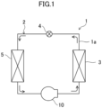
- the air conditioner (1) has a refrigerant circuit (2) filled with refrigerant.
- the refrigerant circuit (2) has the screw compressor (10), a condenser (3), an expansion valve (4), and an evaporator (5).
- the refrigerant circuit (2) performs a vapor compression refrigeration cycle. Arrows in FIG. 1 indicate a direction in which the refrigerant flows.
- the refrigerant compressed by the screw compressor (10) dissipates heat in the condenser (3).
- the refrigerant having dissipated heat is decompressed by the expansion valve (4), is evaporated in the evaporator (5), and is then sucked into the screw compressor (10).
- the screw compressor (10) compresses a refrigerant.
- the screw compressor (10) sucks a low-pressure gas refrigerant and compresses the sucked gas refrigerant.
- the screw compressor (10) discharges the compressed high-pressure gas refrigerant.
- the screw compressor (10) of this embodiment is configured to compress the refrigerant in two stages.
- the screw compressor (10) includes a casing (11), an electric motor (13), a drive shaft (19), and a compression mechanism (30).
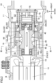
- a casing (11) As illustrated in FIGS. 2 to 4 , the screw compressor (10) includes a casing (11), an electric motor (13), a drive shaft (19), and a compression mechanism (30).
- top,” “bottom,” “right,” and “left” refer to directions when the side surface of the screw compressor (10) illustrated in FIG. 2 is viewed from the front.
- the casing (11) is formed in a horizontally elongated tubular shape.
- the casing (11) has an inlet and an outlet which are not illustrated.
- the casing (11) contains a low-pressure space (S1) and a high-pressure space (S2).
- the low-pressure space (S1) is a space through which a low-pressure gas refrigerant to be sucked into the compression mechanism (30) through the inlet flows.
- the high-pressure space (S2) is a space into which a high-pressure gas refrigerant discharged from the compression mechanism (30) flows.
- the refrigerant in the high-pressure space (S2) flows out of the screw compressor (10) through the outlet.
- a cylinder portion (16) is formed in the casing (11).
- the cylinder portion (16) is formed in substantially cylindrical shape that is horizontally elongated.
- a screw rotor (40) described later is disposed in the cylinder portion (16).
- the electric motor (13) is housed in the casing (11).
- the electric motor (13) is disposed on one end of the casing (11).
- the electric motor (13) has a stator (14) and a rotor (15).
- the stator (14) is fixed to an inner wall of the casing (11).
- the rotor (15) is disposed inside the stator (14).
- the drive shaft (19) is fixed inside the rotor (15).
- the rotational speed of the electric motor (13) can be changed.
- the electric motor (13) is an inverter-driven electric motor.
- the drive shaft (19) is disposed in the casing (11).
- the drive shaft (19) extends along the longitudinal direction of the casing (11).
- the drive shaft (19) extends substantially horizontally.
- the drive shaft (19) is inserted into the cylinder portion (16) along a cylinder axis direction.
- the drive shaft (19) is disposed so that the axial center thereof coincides with the axial center of the cylinder portion (16).
- the drive shaft (19) is driven by the electric motor (13).
- the rotational speed of the drive shaft (19) varies as the rotational speed of the electric motor (13) varies. In other words, the rotational speed of the drive shaft (19) can be changed.
- the drive shaft (19) couples the electric motor (13) and the compression mechanism (30) together.
- the drive shaft (19) is rotatably supported by a first bearing portion (21) and a second bearing portion (22) which are fixed in the cylinder portion (16).
- the first bearing portion (21) is disposed at an intermediate portion of the drive shaft (19).
- the second bearing portion (22) is disposed at the end portion of the drive shaft (19) on the discharge side (end portion opposite to the electric motor (13)).
- the first bearing portion (21) includes a first bearing (21a) and a first bearing holder (21b).
- the second bearing portion (22) includes a second bearing (22a) and a second bearing holder (22b).
- the drive shaft (19) is supported by the bearing holders (21b, 22b) through the bearings (21a, 22a).
- the first bearing (21a) and the second bearing (22a) may be collectively simply referred to as a bearing(s) (21a, 22a).
- the first bearing holder (21b) and the second bearing holder (22b) may be collectively simply referred to as a bearing holder(s) (21b, 22b).
- the bearing holder (21b, 22b) is formed in a substantially cylindrical shape surrounding the entire circumference of the bearing (21a, 22a).
- the outer peripheral surface of the bearing holder is fixed to the inner peripheral surface of the cylinder portion (16).
- the first bearing holder (21b) and the second bearing holder (22b) are arranged so as to sandwich the screw rotor (40).
- Each bearing portion (21) has a tubular peripheral wall (21c, 22c).
- the peripheral wall (21c, 22c) is provided at the outer peripheral edge of an end surface of the bearing holder (21b, 22b) in the axial direction.
- the peripheral wall (21c, 22c) is formed along the inner peripheral surface of the cylinder portion (16).
- the peripheral wall (21c, 22c) is disposed between the inner peripheral surface of the cylinder portion (16) and the outer peripheral surface of an end portion (42, 43) of the screw rotor (40).
- the outer peripheral surface of the peripheral wall (21c, 22c) is fixed to the inner peripheral surface of the cylinder portion (16).
- the inner peripheral surface of the peripheral wall (21c, 22c) is close to the outer peripheral surface of the end portion (42, 43) of the screw rotor (40).
- the peripheral wall (21c, 22c) of the first bearing portion (21) will be referred to as a first peripheral wall (21c)
- the peripheral wall (21c, 22c) of the second bearing portion (22) will be referred to as a second peripheral wall (22c).
- the first peripheral wall (21c) is one example of a flange portion (21c) of the present disclosure.
- the compression mechanism (30) has one cylinder portion (16), one screw rotor (40), two gate rotors (50), and two slide valves (65).
- the cylinder portion (16) houses the screw rotor (40).
- the cylinder portion (16) has a first slit (16a) and a second slit (16b).
- the first slit (16a) and the second slit (16b) are elongated openings extending in the cylinder axis direction.
- the first slit (16a) and the second slit (16b) are arranged adjacent to each other in the circumferential direction.
- the gate rotor (50) penetrates each of the first slit (16a) and the second slit (16b). The first slit (16a) and the second slit (16b) will be described in detail later.
- the cylinder portion (16) includes a valve housing portion (66) in which the slide valve (65) is housed.
- Two valve housing portions (66) are provided in the circumferential direction of the cylinder portion (16).
- Each valve housing portion (66) is formed so as to bulge outward of the cylinder portion (16) in the radial direction.
- the outer peripheral wall of the valve housing portion (66) has a partition wall (66a) separating the low-pressure space (S1) and the high-pressure space (S2) from each other, and a guide wall (66b) extending in the axial direction from the center position of the partition wall (66a) in the width direction thereof toward the high-pressure space (S2).
- the screw rotor (40) is disposed inside the cylinder portion (16).
- the screw rotor (40) is a metal member having a generally columnar shape.
- the screw rotor (40) is fixed to the drive shaft (19).
- the screw rotor (40) rotates as the drive shaft (19) rotates.
- the outer peripheral surface of the screw rotor (40) is close to the inner peripheral surface of the cylinder portion (16).
- first end portion (42) One of end portions of the screw rotor (40) in the cylinder axis direction will be referred to as a first end portion (42), and the other end portion will be referred to as a second end portion (43).
- the first end portion (42) and the second end portion (43) are both formed in a cylindrical shape.
- the first end portion (42) is a suction side end portion of a compression chamber (25) described later.
- the first end portion (42) is a suction side end portion (42) of the present disclosure.
- the second end portion (43) is a discharge side end portion of the compression chamber (25).
- the first end portion (42) is adjacent to the first bearing portion (21).
- the second end portion (43) is adjacent to the second bearing portion (22).
- the outer peripheral surface of the first end portion (42) will be referred to as a first outer peripheral surface (42a), and the end surface of the first end portion (42) will be referred to as a first end surface (42b).
- the outer peripheral surface of the second end portion (43) will be referred to as a second outer peripheral surface (43a), and the end surface of the second end portion (43) will be referred to as a second end surface (43b).
- the first outer peripheral surface (42a) and the second outer peripheral surface (43a) are along the inner peripheral surface of the cylinder portion (16). Specifically, the first outer peripheral surface (42a) is close to the inner surface of the first peripheral wall (21c) of the first bearing portion (21), and the second outer peripheral surface (43a) is close to the inner surface of the second peripheral wall (22c) of the second bearing portion (22).
- the first end surface (42b) and the second end surface (43b) are formed as flat surfaces perpendicular to the cylinder axis direction.
- the first end surface (42b) faces the end surface of the first bearing holder (21b).
- the second end surface (43b) faces the end surface of the second bearing holder (22b). Specifically, the first end surface (42b) is close to the end surface of the first bearing holder (21b), and the second end surface (43b) is close to the end surface of the second bearing holder (22b).
- the outer peripheral surface of the screw rotor (40) has a plurality of screw grooves (41) extending helically.
- the screw groove (41) extends from the first end portion (42) to the second end portion (43) in the axial direction of the screw rotor (40).
- the gate rotor (50) includes a first gate rotor (50a) and a second gate rotor (50b). Each gate rotor (50) has a plurality of gates (53) arranged radially. The gate (53) is inserted into the slit (16a, 16b) of the cylinder portion (16) and meshes with the screw groove (41).
- Each gate rotor (50) is supported by a gate rotor shaft (58).
- the gate rotor shaft (58) extends in the direction perpendicular to the axial direction of the drive shaft (19).
- the gate rotor shaft (58) is housed in a bearing housing (55) defined in the casing (11).
- the gate rotor shaft (58) is rotatably supported through a ball bearing (56) provided in the bearing housing (55).
- the gate rotor (50) and the gate rotor shaft (58) are arranged in a gate rotor chamber (18).
- the gate rotor chamber (18) is defined in the casing (11), and is adjacent to the cylinder portion (16).
- the gate rotor chamber (18) includes a first gate rotor chamber (18a) and a second gate rotor chamber (18b).
- the first gate rotor (50a) is disposed in the first gate rotor chamber (18a).
- the second gate rotor (50b) is disposed in the second gate rotor chamber (18b).
- the first gate rotor chamber (18a) is configured to supply a refrigerant to a first compression chamber (23) described later.
- the second gate rotor chamber (18b) is configured to supply a refrigerant having flowed out of the first compression chamber (23) to a second compression chamber (24) described later.
- the slide valve (65) is housed in the valve housing portion (66).
- the slide valve (65) is slidable in the axial direction of the cylinder portion (16) by a drive mechanism (71) described later. While being inserted into the valve housing portion (66), the slide valve (65) faces the outer peripheral surface of the screw rotor (40).
- the drive mechanism (71) has the cylinder portion (16), a piston (73), a piston rod (74), an arm (75), a connecting rod (76), and a spring (77).
- the cylinder portion (16) is formed on the right sidewall surface of a fixed plate (29).
- the piston (73) is loaded in the cylinder portion (16).
- One end of the piston rod (74) is fixed to the center of the piston (73) and extends leftward.
- the arm (75) is coupled to the other end of the piston rod (74).
- the connecting rod (76) couples the arm (75) and the slide valve (65) to each other.
- the spring (77) is provided on the connecting rod (76) to bias the arm (75) rightward.
- the drive mechanism (71) adjusts the position of the slide valve (65) by controlling movement of the piston (73) through regulation of a gas pressure applied to the right and left end faces of the piston (73).
- the slide valve (65) is capable of adjusting the position of the screw rotor (40) in the axial direction.
- the slide valve (65) can be used as an unloading mechanism that returns a refrigerant that is being compressed in the compression chamber (25) toward the suction side to change an operating capacity.
- the slide valve (65) can also be used as a compression ratio regulation mechanism that adjusts the timing when the refrigerant is discharged from the compression chamber (25) to regulate a compression ratio (internal volume ratio).
- the compression chamber (25) surrounded by the inner peripheral surface of the cylinder portion (16), the screw groove (41) of the screw rotor (40), and the two gate rotors (50) is formed.
- the cylinder portion (16) is provided with a fixed discharge port (not illustrated) permanently communicating with the compression chamber (25) regardless of the position of the slide valve (65).
- the fixed discharge port is provided so as to keep the compression chamber (25) from being hermetically closed in order to avoid liquid compression at the timing when the screw compressor (10) is actuated or is at a low load.
- the compression chamber (25) includes a first compression chamber (23) which is on a low-stage side in the two-stage compression and a second compression chamber (24) which is on a high-stage side.
- the first compression chamber (23) and the second compression chamber (24) are formed inside the cylinder portion (16) by the screw rotor (40) and the gate rotors (50).
- the first compression chamber (23) compresses the refrigerant at a suction pressure introduced into the casing (11) to an intermediate pressure higher than the suction pressure.
- the second compression chamber (24) compresses the intermediate-pressure refrigerant to a discharge pressure (high pressure) higher than the intermediate pressure.
- the low-pressure space (S1) communicates with the first compression chamber (23) through the first gate rotor chamber (18a).
- the low-pressure space (S1), the first gate rotor chamber (18a), the first compression chamber (23), the second gate rotor chamber (18b) serving as an intermediate-pressure space, the second compression chamber (24), and the high-pressure space (S2) are connected together in an ascending order of the pressure of the refrigerant.
- the first slit (16a) allows the low-pressure space (S1) and the first gate rotor chamber (18a) to communicate with the first compression chamber (23).
- the second slit (16b) allows the second gate rotor chamber (18b) serving as the intermediate-pressure space to communicate with the second compression chamber (24).
- the first slit (16a) forms a first inlet through which the low-pressure refrigerant in the low-pressure space (S1) is introduced into the first compression chamber (23).
- the second slit (16b) forms a second inlet through which the refrigerant in the intermediate-pressure space is introduced into the second compression chamber (24).
- the hatched compression chamber (25) (strictly speaking, suction chamber) communicates with a suction-side space.
- the screw groove (41) corresponding to this compression chamber (25) meshes with the gate (53) of the gate rotor (50).
- the gate (53) relatively moves toward the terminal end of the screw groove (41), and the volume of the compression chamber (25) increases accordingly. As a result, the refrigerant is sucked into the compression chamber (25).
- a compression stroke illustrated in FIG. 5 is performed.
- the hatched compression chamber (25) is completely closed. That is, the screw groove (41) corresponding to the compression chamber (25) is separated by the gate (53) from the suction-side space.
- the gate (53) approaches the terminal end of the screw groove (41) along with rotation of the screw rotor (40)
- the volume of the compression chamber (25) gradually decreases. As a result, the refrigerant in the compression chamber (25) is compressed.
- a discharge stroke illustrated in FIG. 5 is performed.
- the hatched compression chamber (25) (strictly speaking, discharge chamber) communicates with a fixed discharge port via a discharge-side end portion.
- the gate (53) approaches the terminal end of the screw groove (41) along with rotation of the screw rotor (40), the compressed refrigerant is pushed out from the compression chamber (25) through the fixed discharge port to the discharge-side space.
- the refrigerant sucked into the casing (11) flows into the low-pressure space (S1), and is then introduced from the low-pressure space (S1) into the first gate rotor chamber (18a).
- the low-pressure refrigerant in the first gate rotor chamber (18a) is sucked into the first compression chamber (23) through the first slit (16a).
- the intermediate-pressure refrigerant compressed in the first compression chamber (23) flows out of the first compression chamber (23), and flows into the second gate rotor chamber (18b) serving as an intermediate-pressure space.
- the intermediate-pressure refrigerant in the second gate rotor chamber (18b) is sucked into the second compression chamber (24) through the second slit (16b).
- the high-pressure refrigerant compressed in the second compression chamber (24) flows out of the second compression chamber (24), and flows into the high-pressure space (S2) serving as a second space.
- the refrigerant having flowed into the high-pressure space (S2) is separated from oil by an oil separator (not illustrated), and flows out of the casing (11) through an outlet (10b).
- the suction-side end portion of the screw rotor needs to have a suction cutless structure for sealing the inner peripheral surface of the cylinder portion and the outer peripheral surface of the screw rotor (equivalent to the first end portion (42) of this embodiment).
- the refrigerant sucked into that screw compressor flows through the low-pressure space (S 1), the first gate rotor chamber (18a), the first compression chamber (23), the second gate rotor chamber (18b) serving as an intermediate-pressure space, the second compression chamber (24), and the high-pressure space (S2) in this order.
- the intermediate-pressure discharged refrigerant compressed in the first compression chamber (23) passes outside the first end portion (42) which is the suction-side end portion of the screw rotor (40) before flowing into the second gate rotor chamber (18b).
- the pressure is low due to the refrigerant sucked into the first compression chamber (23), and thus there is a pressure difference between the outside and inside of the first end portion (42).
- the intermediate-pressure refrigerant outside the first end portion (42) may flow through a gap between the first end portion (42) and the cylinder portion (16) and flow into the first compression chamber (23) (as indicated by a broken line in FIG. 9 ).
- the intermediate-pressure refrigerant flows into the suction side of the first compression chamber (23), a difference between the suction pressure and the discharge pressure of refrigerants in the first compression chamber (23) is reduced, and thus a compression efficiency is degraded.
- the screw compressor (10) of this embodiment is configured so that a seal portion (80) for reducing the flow of the refrigerant is provided in a first surface (F) facing the outer peripheral surface (42a) of the first end portion (42) as a suction-side end portion or the first end surface (42b) of the suction-side end portion (42) in the axial direction.
- the seal portion (80) will be specifically described below.
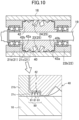
- the seal portion (80) of this embodiment is provided in the first bearing portion (21). Specifically, the seal portion (80) is provided on the inner peripheral surface (F) of the first peripheral wall (21c).
- the inner peripheral surface (F) of the first peripheral wall (21c) is one example of the first surface (F) facing the first end portion (42) of the present disclosure.
- the seal portion (80) of this embodiment is a labyrinth seal.
- the first peripheral wall (21c) has a plurality of recessed grooves (81) formed over the entire circumference of the inner peripheral surface (F) and arranged at regular intervals in the axial direction.
- the plurality of recessed grooves (81) forms an expansion chamber.
- the intermediate-pressure refrigerant flowing into a clearance (flow path) between the first end portion (42) and the first bearing holder (21b) and flowing toward the first compression chamber (23) expands (decompressed) by flowing into the recessed groove (81), and then flows into the flow path.
- the refrigerant expands (decompressed) by flowing into the next recessed groove (81), and then flows into the flow path.
- the intermediate-pressure refrigerant repeatedly flows into the flow path from the expansion chamber.
- a pressure loss occurs. Generation of the pressure loss can reduce the intermediate-pressure refrigerant flowing into the first compression chamber (23).
- the first end portion (42) (suction-side end portion) of the screw rotor (40) is formed in the cylindrical shape so that the first outer peripheral surface (42a) is along the inner peripheral surface of the cylinder portion (16).
- the seal portion (80) for reducing the flow of the refrigerant is provided in the first surface (F) facing the first end portion (42).
- the intermediate-pressure refrigerant discharged from the first compression chamber (23) flows through the space outside the first end portion (42) when moving to the inlet port of the second compression chamber (24).
- the space inside the first end portion (42) is the first compression chamber (23) and forms the space into which the low-pressure refrigerant is sucked, and thus the pressure difference is generated through the first end portion (42).
- the seal portion (80) is provided in the first surface (F) facing the first end portion (42), thereby reducing the intermediate-pressure refrigerant flowing between the first end portion (42) and the first surface (F).
- the screw compressor (10) of this embodiment includes the first bearing portion (21) fixed in the cylinder portion (16) and supporting the drive shaft (19).
- the first bearing portion (21) is adjacent to the first end portion (42), and the seal portion (80) is provided in the first bearing portion (21).
- the first surface (F) facing the first end portion (42) is in the first bearing holder (21b), and the seal portion (80) is provided in the first bearing holder (21b).
- the first bearing portion (21) has a bearing function for the drive shaft (19) and a sealing function for reducing flow of the refrigerant.
- the seal portion (80) can be provided before the first bearing holder (21b) is attached to the inside of the cylinder portion (16), and thus the seal portion (80) can be formed more easily than if the seal portion (80) is provided in the cylinder portion (16).
- the first bearing portion (21) has the first peripheral wall (21c) (flange portion) disposed between the inner surface of the cylinder portion (16) and the outer peripheral surface of the first end portion (42), and the seal portion (80) is provided in the first peripheral wall (21c).
- the seal portion (80) can be provided in the inner peripheral surface of the first peripheral wall (21c). Further, the inner peripheral surface of the first peripheral wall (21c) and the first end surface (42b) can increase the area of contact between the first bearing holder (21b) and the first end portion (42). With such an increase in the area, the flow path through which the refrigerant flows and which is the clearance between the first bearing holder (21b) and the first end portion (42) can be lengthened, and thus an effect of reducing flow of the refrigerant can be enhanced in addition to the effect of the seal portion (80).
- the compression chamber (25) includes the first compression chamber (23) in which the fluid at the suction pressure introduced into the casing (11) is compressed to the intermediate pressure and the second compression chamber (24) in which the fluid at the intermediate pressure is compressed to the discharge pressure.
- part of the intermediate-pressure fluid discharged from the first compression chamber (23) is less sucked into the first compression chamber (23) again through the suction-side end portion (42) while moving to the second compression chamber (24).
- the seal portion (80) is a labyrinth seal. Accordingly, the seal portion (80) can be relatively easily formed.
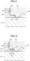
- the seal portion (80) of this variation is a surface texture (surface texturing).
- the surface texture is formed on the inner peripheral surface of the first peripheral wall (21c).
- a Rayleigh step for generating a positive pressure and a reverse Rayleigh step for generating a negative pressure are formed as necessary.
- friction between the inner peripheral surface of the first peripheral wall (21c) and the outer peripheral surface of the first end portion (42) can be reduced.
- the reverse Rayleigh step the refrigerant flowing into the clearance between the inner peripheral surface of the first peripheral wall (21c) and the outer peripheral surface of the first end portion (42) can be sucked back.
- the reverse Rayleigh step may be employed to prevent the intermediate-pressure refrigerant from flowing into the first compression chamber (23).
- the seal portion (80) of this variation is formed on the surface of the first bearing holder (21b) facing the first end surface (42b).
- the surface facing the first end surface (42b) is one example of the first surface (F) of the present disclosure.
- the seal portion (80) is a labyrinth seal
- the plurality of recessed grooves (81) are formed at regular intervals on the first end surface (42b) in a concentric manner about the cylinder axis of the first bearing holder (21b).
- the seal portions (80) of this variation are formed on the inner peripheral surface of the first peripheral wall (21c) and the surface of the first bearing holder (21b) facing the first end surface (42b).
- the seal portions (80) provided on both surfaces facing the first end portion (42) can reliably reduce the refrigerant flowing through the clearance between the first end portion (42) and the bearing holder (21b, 22b).
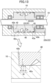
- the first bearing portion (21) of this variation does not have the first bearing holder (21b).
- the first bearing (21a) is embedded in the cylinder portion (16), and a cylinder end surface (26) facing the first end surface (42b) is formed inside the cylinder portion (16).
- the first surface (F) of the present disclosure is the inner peripheral surface of the cylinder portion (16) facing the first outer peripheral surface (42a) and the cylinder end surface (26) facing the first end surface (42b).
- the seal portion (80) is provided on the inner peripheral surface of the cylinder portion (16) facing the first outer peripheral surface (42a).
- the seal portion (80) may be provided on the cylinder end surface (26) facing the end surface of the first end portion (42).
- the seal portions (80) may be provided on both the inner peripheral surface of the cylinder portion (16) facing the first outer peripheral surface (42a) and the cylinder end surface (26) facing the end surface of the first end portion (42).
- the refrigerant circuit (2) of this variation has an economizer circuit (90).
- the economizer circuit (90) of this variation supplies an intermediate-pressure refrigerant to the compression chamber (25). Arrows in FIG. 14 indicate the direction in which the refrigerant flows.
- a gas-liquid separation space (S3) in which the refrigerant is separated into gas and liquid is formed.
- the gas-liquid separation space (S3) is adjacent to the suction side of the compression chamber (25).
- the high-pressure space (S2) in the casing (11) is adjacent to the discharge side of the compression chamber (25).
- An inlet of refrigerant is provided on the suction side of the compression chamber (25).
- the screw compressor (10) of this variation is configured as a single-stage compressor.
- the inlet side of the condenser (3) communicates with the high-pressure space of the screw compressor (10).
- the outlet side of the condenser (3) communicates with the gas-liquid separation space (S3) of the screw compressor (10).
- a first expansion valve (4a) is provided between the condenser (3) and the gas-liquid separation space (S3).
- the inlet side of the evaporator (5) communicates with the gas-liquid separation space (S3) of the screw compressor (10).
- the outlet side of the evaporator (5) communicates with the suction side of the compression chamber (25) of the screw compressor (10).
- a second expansion valve (4b) is provided between the gas-liquid separation space (S3) and the evaporator (5).
- the economizer circuit (90) makes the gas-liquid separation space (S3) and the compression chamber (25) communicate with each other.
- the intermediate-pressure gas refrigerant in the gas-liquid separation space (S3) flows into the intermediate-pressure space of the compression chamber (25).
- a flow rate control valve (91) is connected to the economizer circuit (90). The flow rate control valve (91) controls the flow rate of the refrigerant flowing through the economizer circuit (90).
- the suction side of the compression chamber (25) is adjacent to the gas-liquid separation space (S3).
- the seal portion (80) can reduce the intermediate-pressure refrigerant in the gas-liquid separation space (S3) flowing into the compression chamber (25) through the clearance between the first end portion (42) of the screw rotor (40) and the cylinder portion (16).
- the seal portion (80) may also be provided in the second bearing holder (22b).
- the seal portion (80) may be provided on the inner peripheral surface of the second peripheral wall (22c).
- the first bearing holder (21b) does not necessarily have the first peripheral wall (21c).
- the first surface (F) of the present disclosure is the inner peripheral surface of the cylinder portion (16) facing the first outer peripheral surface (42a) and the end surface of the bearing holder (21b, 22b) facing the first end surface (42b).
- the seal portion(s) (80) is provided on the inner peripheral surface of the cylinder portion (16) facing the first outer peripheral surface (42a), or on the end surface of the bearing holder (21b, 22b) facing the first end surface (42b), or on both of them.
- the seal portion (80) only has to reduce flow between the space inside the first end portion (42) (the compression chamber) and the space outside the first end portion (42), and the seal portion (80) may be configured to reduce the flow in any one of those spaces.
- the labyrinth structure of the seal portion (80) is not particularly limited.
- the labyrinth may be, e.g., an axial labyrinth, a radial labyrinth, or a centered labyrinth.
- the refrigeration apparatus (1) may be applied to a water heater, a chiller unit, or a cooling apparatus that cools air in an internal space.
- the present disclosure is useful for a screw compressor and a refrigeration apparatus.
Landscapes
- Engineering & Computer Science (AREA)
- Mechanical Engineering (AREA)
- General Engineering & Computer Science (AREA)
- Applications Or Details Of Rotary Compressors (AREA)
Abstract
Description
- The present disclosure relates to a screw compressor and a refrigeration apparatus.
-
Patent Document 1 discloses a screw compressor including a screw rotor and a gate rotor. The screw rotor is inserted into a cylinder, and a gate of the gate rotor meshes with a screw groove of the screw rotor, thereby forming a compression chamber. - Patent Document 1:
Japanese Unexamined Patent Publication No. 2009-197794 - Some screw compressors have a suction cutless structure in which a suction-side end portion of a screw rotor closes a compression chamber. Such a suction-side end portion is formed in a cylindrical shape so that the outer peripheral surface thereof is along the inner peripheral surface of a cylinder portion.
- Due to such a suction Cutless shape, a refrigerant may flow through a clearance between the suction-side end portion and the cylinder inner surface due to a pressure difference between a space near the suction-side end portion in the compression chamber and a space adjacent to the suction-side end portion outside the compression chamber. For example, when an intermediate-pressure refrigerant in the space adjacent to the suction-side end portion outside the compression chamber leaks into the suction side of the compression chamber, a suction pressure increases and a compression efficiency decreases.
- It is an object of the present disclosure to reduce the flow of refrigerant around the suction-side end portion of the compression chamber of the screw compressor.
- A first aspect of the present disclosure is directed to a screw compressor including: a casing (11) containing a cylinder portion (16); an electric motor (13) disposed in the casing (11); a drive shaft (19) connected to the electric motor (13) and configured to be driven to rotate axially; a screw rotor (40) disposed in the cylinder portion (16) and connected to the drive shaft (19); and a gate rotor (50) having a gate (53) configured to mesh with a screw groove (41) of the screw rotor (40), wherein in the cylinder portion (16), a compression chamber is formed by the screw rotor (40) and the gate (53), a suction-side end portion (42) of the screw rotor (40) is formed in a cylindrical shape so that an outer peripheral surface (42a) of the suction-side end portion (42) is along an inner peripheral surface of the cylinder portion (16), a seal portion (80) configured to reduce a flow of fluid is provided on a first surface (F) facing the outer peripheral surface (42a) of the suction-side end portion (42) or a first end surface (42b) of the suction-side end portion (42) in an axial direction.
- The space of the compression chamber (25) closer to the suction-side end portion (42) is at a low pressure due to a sucked refrigerant. Thus, if a space adjacent to the compression chamber (25) via the suction-side end portion (42) is at an intermediate pressure, the refrigerant is forced to flow into the compression chamber (25) through a clearance between the first surface (F) and the suction-side end portion (42) due to a refrigerant pressure difference (differential pressure). However, in the first aspect, the seal portion (80) provided on the first surface (F) can reduce the refrigerant flowing through the clearance between the first surface (F) and the suction-side end portion (42). As a result, the differential pressure in the compression chamber (25) can be sufficiently ensured, and degradation of the performance of the screw compressor can be reduced.
- A second aspect of the present disclosure is an embodiment of the first aspect. In the second aspect, the screw compressor further includes a bearing portion (21) fixed in the cylinder portion (16) and supporting the drive shaft (19), wherein the bearing portion (21) is adjacent to the suction-side end portion (42), and the seal portion (80) is provided in the bearing portion (21).
- In a second aspect, the first surface (F) facing the suction-side end portion (42) is provided in the bearing portion (21). The seal portion (80) formed on the first surface (F) of the bearing portion (21) can reduce the refrigerant flowing between the suction-side end portion (42) and the bearing portion (21). In this manner, the bearing portion (21) has a bearing function and a seal function.
- A third aspect of the present disclosure is an embodiment of the second aspect. In the third aspect, the seal portion (80) is provided on the first surface (F) of the bearing portion (21) facing an end surface of the suction-side end portion (42) in the axial direction.
- In the third aspect, the seal portion (80) can be provided on the end surface of the bearing portion (21).
- A fourth aspect of the present disclosure is an embodiment of the second or third aspect. In the fourth aspect, the bearing portion (21) has a flange portion (21c) disposed between an inner surface of the cylinder portion (16) and the outer peripheral surface (42a) of the suction-side end portion (42), and the seal portion (80) is provided in the flange portion (21c).
- In the fourth aspect, the inner peripheral surface of the flange portion (21c) is the first surface (F), and the seal portion (80) is provided on the inner peripheral surface of the flange portion (21c). In this manner, the seal portion (80) can also be provided on the bearing portion (21) having the flange portion (21c).
- A fifth aspect of the present disclosure is an embodiment of any one of the first to fourth aspects. In the fifth aspect, the gate rotor (50) has a first gate rotor (50a) and a second gate rotor (50b), and the compression chamber (25) includes a first compression chamber (23) which is formed by the first gate rotor (50a) and the screw rotor (40) and in which fluid at a suction pressure introduced into the casing (11) is compressed to an intermediate pressure, and a second compression chamber (24) which is formed by the second gate rotor (50b) and the screw rotor (40) and in which the fluid at the intermediate pressure is compressed to a discharge pressure.
- In the fifth aspect, the screw compressor is configured as a two-stage compression type. While moving to the inlet of the second compression chamber (24), the intermediate-pressure refrigerant discharged from the first compression chamber (23) can be less sucked into the first compression chamber (23) again through the clearance between the first surface (F) and the suction-side end portion (42).
- A sixth aspect of the present disclosure is an embodiment of any one of the first to fifth aspects. In the sixth aspect, the seal portion (80) is a labyrinth seal.
- A seventh aspect of the present disclosure is an embodiment of any one of the first to fifth aspects. In the seventh aspect, the seal portion (80) is a surface texture.
- An eighth aspect of the present disclosure is directed to a refrigeration apparatus including the screw compressor of any one of the first to seventh aspects.
-
-
FIG. 1 is a schematic piping system diagram of a refrigeration apparatus according to an embodiment. -
FIG. 2 is a vertical sectional view of a main part of a schematic configuration of a screw compressor of an embodiment. -
FIG. 3 is a sectional view taken along line III-III inFIG. 2 . -
FIG. 4 is a perspective view of a screw rotor and a gate rotor meshing with each other. -
FIG. 5 is a schematic plan view of the screw compressor performing a suction stroke, a compression stroke, and a discharge stroke . -
FIG. 6 is a perspective view illustrating the flow of refrigerant during low-stage compression. -
FIG. 7 is a perspective view illustrating the flow of refrigerant during high-stage compression. -
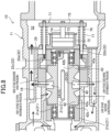
FIG. 8 is a side sectional view illustrating the flow of refrigerant in a compression mechanism. -
FIG. 9 is an enlarged side sectional view illustrating the flow of refrigerant around a first end portion of the compression mechanism. -
FIG. 10 is a side sectional view of part of the compression mechanism and an enlarged view thereof for describing a seal portion of the present embodiment. -
FIG. 11 shows a screw compressor of a second variation and corresponds to an enlarged view ofFIG. 10 . -
FIG. 12 shows a screw compressor of a third variation and corresponds to the enlarged view ofFIG. 10 . -
FIG. 13 shows a screw compressor of a fourth variation and corresponds toFIG. 10 . -
FIG. 14 is a piping system diagram of a refrigerant circuit to which a screw compressor of a fifth variation is connected. - Embodiments of the present invention will be described in detail below with reference to the drawings. The following embodiments are merely exemplary ones in nature, and are not intended to limit the scope, application, or uses of the invention. Features of the embodiments, variations, and other embodiments described below can be combined or partially substituted within the range where the present invention can be embodied.
- As illustrated in
FIG. 1 , a screw compressor (10) of this embodiment is provided in an air conditioner (1) that conditions air in an indoor space. The air conditioner (1) is one example of a refrigeration apparatus (1) of the present disclosure. The air conditioner (1) has a refrigerant circuit (2) filled with refrigerant. - The refrigerant circuit (2) has the screw compressor (10), a condenser (3), an expansion valve (4), and an evaporator (5). The refrigerant circuit (2) performs a vapor compression refrigeration cycle. Arrows in
FIG. 1 indicate a direction in which the refrigerant flows. In the refrigeration cycle, the refrigerant compressed by the screw compressor (10) dissipates heat in the condenser (3). The refrigerant having dissipated heat is decompressed by the expansion valve (4), is evaporated in the evaporator (5), and is then sucked into the screw compressor (10). - The screw compressor (10) compresses a refrigerant. The screw compressor (10) sucks a low-pressure gas refrigerant and compresses the sucked gas refrigerant. The screw compressor (10) discharges the compressed high-pressure gas refrigerant. The screw compressor (10) of this embodiment is configured to compress the refrigerant in two stages.
- As illustrated in
FIGS. 2 to 4 , the screw compressor (10) includes a casing (11), an electric motor (13), a drive shaft (19), and a compression mechanism (30). Hereinafter, the terms "top," "bottom," "right," and "left" refer to directions when the side surface of the screw compressor (10) illustrated inFIG. 2 is viewed from the front. - The casing (11) is formed in a horizontally elongated tubular shape. The casing (11) has an inlet and an outlet which are not illustrated. The casing (11) contains a low-pressure space (S1) and a high-pressure space (S2). The low-pressure space (S1) is a space through which a low-pressure gas refrigerant to be sucked into the compression mechanism (30) through the inlet flows. The high-pressure space (S2) is a space into which a high-pressure gas refrigerant discharged from the compression mechanism (30) flows. The refrigerant in the high-pressure space (S2) flows out of the screw compressor (10) through the outlet. A cylinder portion (16) is formed in the casing (11). The cylinder portion (16) is formed in substantially cylindrical shape that is horizontally elongated. A screw rotor (40) described later is disposed in the cylinder portion (16).
- The electric motor (13) is housed in the casing (11). The electric motor (13) is disposed on one end of the casing (11). The electric motor (13) has a stator (14) and a rotor (15). The stator (14) is fixed to an inner wall of the casing (11). The rotor (15) is disposed inside the stator (14). The drive shaft (19) is fixed inside the rotor (15). The rotational speed of the electric motor (13) can be changed. In this example, the electric motor (13) is an inverter-driven electric motor.
- The drive shaft (19) is disposed in the casing (11). The drive shaft (19) extends along the longitudinal direction of the casing (11). The drive shaft (19) extends substantially horizontally. The drive shaft (19) is inserted into the cylinder portion (16) along a cylinder axis direction. The drive shaft (19) is disposed so that the axial center thereof coincides with the axial center of the cylinder portion (16).
- The drive shaft (19) is driven by the electric motor (13). The rotational speed of the drive shaft (19) varies as the rotational speed of the electric motor (13) varies. In other words, the rotational speed of the drive shaft (19) can be changed. The drive shaft (19) couples the electric motor (13) and the compression mechanism (30) together.
- The drive shaft (19) is rotatably supported by a first bearing portion (21) and a second bearing portion (22) which are fixed in the cylinder portion (16). The first bearing portion (21) is disposed at an intermediate portion of the drive shaft (19). The second bearing portion (22) is disposed at the end portion of the drive shaft (19) on the discharge side (end portion opposite to the electric motor (13)).
- The first bearing portion (21) includes a first bearing (21a) and a first bearing holder (21b). The second bearing portion (22) includes a second bearing (22a) and a second bearing holder (22b). The drive shaft (19) is supported by the bearing holders (21b, 22b) through the bearings (21a, 22a). In the following description, the first bearing (21a) and the second bearing (22a) may be collectively simply referred to as a bearing(s) (21a, 22a). The first bearing holder (21b) and the second bearing holder (22b) may be collectively simply referred to as a bearing holder(s) (21b, 22b).
- The bearing holder (21b, 22b) is formed in a substantially cylindrical shape surrounding the entire circumference of the bearing (21a, 22a). The outer peripheral surface of the bearing holder is fixed to the inner peripheral surface of the cylinder portion (16). The first bearing holder (21b) and the second bearing holder (22b) are arranged so as to sandwich the screw rotor (40).
- Each bearing portion (21) has a tubular peripheral wall (21c, 22c). The peripheral wall (21c, 22c) is provided at the outer peripheral edge of an end surface of the bearing holder (21b, 22b) in the axial direction. The peripheral wall (21c, 22c) is formed along the inner peripheral surface of the cylinder portion (16). Specifically, the peripheral wall (21c, 22c) is disposed between the inner peripheral surface of the cylinder portion (16) and the outer peripheral surface of an end portion (42, 43) of the screw rotor (40). The outer peripheral surface of the peripheral wall (21c, 22c) is fixed to the inner peripheral surface of the cylinder portion (16). The inner peripheral surface of the peripheral wall (21c, 22c) is close to the outer peripheral surface of the end portion (42, 43) of the screw rotor (40). The peripheral wall (21c, 22c) of the first bearing portion (21) will be referred to as a first peripheral wall (21c), and the peripheral wall (21c, 22c) of the second bearing portion (22) will be referred to as a second peripheral wall (22c). The first peripheral wall (21c) is one example of a flange portion (21c) of the present disclosure.
- The compression mechanism (30) has one cylinder portion (16), one screw rotor (40), two gate rotors (50), and two slide valves (65).
- The cylinder portion (16) houses the screw rotor (40). The cylinder portion (16) has a first slit (16a) and a second slit (16b). The first slit (16a) and the second slit (16b) are elongated openings extending in the cylinder axis direction. The first slit (16a) and the second slit (16b) are arranged adjacent to each other in the circumferential direction. The gate rotor (50) penetrates each of the first slit (16a) and the second slit (16b). The first slit (16a) and the second slit (16b) will be described in detail later.
- The cylinder portion (16) includes a valve housing portion (66) in which the slide valve (65) is housed. Two valve housing portions (66) are provided in the circumferential direction of the cylinder portion (16). Each valve housing portion (66) is formed so as to bulge outward of the cylinder portion (16) in the radial direction. The outer peripheral wall of the valve housing portion (66) has a partition wall (66a) separating the low-pressure space (S1) and the high-pressure space (S2) from each other, and a guide wall (66b) extending in the axial direction from the center position of the partition wall (66a) in the width direction thereof toward the high-pressure space (S2).
- The screw rotor (40) is disposed inside the cylinder portion (16). The screw rotor (40) is a metal member having a generally columnar shape. The screw rotor (40) is fixed to the drive shaft (19). The screw rotor (40) rotates as the drive shaft (19) rotates. The outer peripheral surface of the screw rotor (40) is close to the inner peripheral surface of the cylinder portion (16).
- One of end portions of the screw rotor (40) in the cylinder axis direction will be referred to as a first end portion (42), and the other end portion will be referred to as a second end portion (43). The first end portion (42) and the second end portion (43) are both formed in a cylindrical shape. The first end portion (42) is a suction side end portion of a compression chamber (25) described later. The first end portion (42) is a suction side end portion (42) of the present disclosure. The second end portion (43) is a discharge side end portion of the compression chamber (25).
- The first end portion (42) is adjacent to the first bearing portion (21). The second end portion (43) is adjacent to the second bearing portion (22). Hereinafter, the outer peripheral surface of the first end portion (42) will be referred to as a first outer peripheral surface (42a), and the end surface of the first end portion (42) will be referred to as a first end surface (42b). The outer peripheral surface of the second end portion (43) will be referred to as a second outer peripheral surface (43a), and the end surface of the second end portion (43) will be referred to as a second end surface (43b).
- The first outer peripheral surface (42a) and the second outer peripheral surface (43a) are along the inner peripheral surface of the cylinder portion (16). Specifically, the first outer peripheral surface (42a) is close to the inner surface of the first peripheral wall (21c) of the first bearing portion (21), and the second outer peripheral surface (43a) is close to the inner surface of the second peripheral wall (22c) of the second bearing portion (22).
- The first end surface (42b) and the second end surface (43b) are formed as flat surfaces perpendicular to the cylinder axis direction. The first end surface (42b) faces the end surface of the first bearing holder (21b). The second end surface (43b) faces the end surface of the second bearing holder (22b). Specifically, the first end surface (42b) is close to the end surface of the first bearing holder (21b), and the second end surface (43b) is close to the end surface of the second bearing holder (22b).
- The outer peripheral surface of the screw rotor (40) has a plurality of screw grooves (41) extending helically. The screw groove (41) extends from the first end portion (42) to the second end portion (43) in the axial direction of the screw rotor (40).
- The gate rotor (50) includes a first gate rotor (50a) and a second gate rotor (50b). Each gate rotor (50) has a plurality of gates (53) arranged radially. The gate (53) is inserted into the slit (16a, 16b) of the cylinder portion (16) and meshes with the screw groove (41).
- Each gate rotor (50) is supported by a gate rotor shaft (58). The gate rotor shaft (58) extends in the direction perpendicular to the axial direction of the drive shaft (19). The gate rotor shaft (58) is housed in a bearing housing (55) defined in the casing (11). The gate rotor shaft (58) is rotatably supported through a ball bearing (56) provided in the bearing housing (55). The gate rotor (50) and the gate rotor shaft (58) are arranged in a gate rotor chamber (18).
- The gate rotor chamber (18) is defined in the casing (11), and is adjacent to the cylinder portion (16). The gate rotor chamber (18) includes a first gate rotor chamber (18a) and a second gate rotor chamber (18b). The first gate rotor (50a) is disposed in the first gate rotor chamber (18a). The second gate rotor (50b) is disposed in the second gate rotor chamber (18b). The first gate rotor chamber (18a) is configured to supply a refrigerant to a first compression chamber (23) described later. The second gate rotor chamber (18b) is configured to supply a refrigerant having flowed out of the first compression chamber (23) to a second compression chamber (24) described later.
- The slide valve (65) is housed in the valve housing portion (66). The slide valve (65) is slidable in the axial direction of the cylinder portion (16) by a drive mechanism (71) described later. While being inserted into the valve housing portion (66), the slide valve (65) faces the outer peripheral surface of the screw rotor (40).
- The drive mechanism (71) has the cylinder portion (16), a piston (73), a piston rod (74), an arm (75), a connecting rod (76), and a spring (77). The cylinder portion (16) is formed on the right sidewall surface of a fixed plate (29). The piston (73) is loaded in the cylinder portion (16). One end of the piston rod (74) is fixed to the center of the piston (73) and extends leftward. The arm (75) is coupled to the other end of the piston rod (74). The connecting rod (76) couples the arm (75) and the slide valve (65) to each other. The spring (77) is provided on the connecting rod (76) to bias the arm (75) rightward. The drive mechanism (71) adjusts the position of the slide valve (65) by controlling movement of the piston (73) through regulation of a gas pressure applied to the right and left end faces of the piston (73).
- The slide valve (65) is capable of adjusting the position of the screw rotor (40) in the axial direction. The slide valve (65) can be used as an unloading mechanism that returns a refrigerant that is being compressed in the compression chamber (25) toward the suction side to change an operating capacity. The slide valve (65) can also be used as a compression ratio regulation mechanism that adjusts the timing when the refrigerant is discharged from the compression chamber (25) to regulate a compression ratio (internal volume ratio).
- In the compression mechanism (30) of this embodiment, the compression chamber (25) surrounded by the inner peripheral surface of the cylinder portion (16), the screw groove (41) of the screw rotor (40), and the two gate rotors (50) is formed.
- The cylinder portion (16) is provided with a fixed discharge port (not illustrated) permanently communicating with the compression chamber (25) regardless of the position of the slide valve (65). The fixed discharge port is provided so as to keep the compression chamber (25) from being hermetically closed in order to avoid liquid compression at the timing when the screw compressor (10) is actuated or is at a low load.
- The compression chamber (25) includes a first compression chamber (23) which is on a low-stage side in the two-stage compression and a second compression chamber (24) which is on a high-stage side. The first compression chamber (23) and the second compression chamber (24) are formed inside the cylinder portion (16) by the screw rotor (40) and the gate rotors (50). The first compression chamber (23) compresses the refrigerant at a suction pressure introduced into the casing (11) to an intermediate pressure higher than the suction pressure. The second compression chamber (24) compresses the intermediate-pressure refrigerant to a discharge pressure (high pressure) higher than the intermediate pressure.
- In this embodiment, the low-pressure space (S1) communicates with the first compression chamber (23) through the first gate rotor chamber (18a). The low-pressure space (S1), the first gate rotor chamber (18a), the first compression chamber (23), the second gate rotor chamber (18b) serving as an intermediate-pressure space, the second compression chamber (24), and the high-pressure space (S2) are connected together in an ascending order of the pressure of the refrigerant.
- The first slit (16a) allows the low-pressure space (S1) and the first gate rotor chamber (18a) to communicate with the first compression chamber (23). The second slit (16b) allows the second gate rotor chamber (18b) serving as the intermediate-pressure space to communicate with the second compression chamber (24). The first slit (16a) forms a first inlet through which the low-pressure refrigerant in the low-pressure space (S1) is introduced into the first compression chamber (23). The second slit (16b) forms a second inlet through which the refrigerant in the intermediate-pressure space is introduced into the second compression chamber (24).
- In a suction stroke illustrated in
FIG. 5 , the hatched compression chamber (25) (strictly speaking, suction chamber) communicates with a suction-side space. The screw groove (41) corresponding to this compression chamber (25) meshes with the gate (53) of the gate rotor (50). When the screw rotor (40) rotates, the gate (53) relatively moves toward the terminal end of the screw groove (41), and the volume of the compression chamber (25) increases accordingly. As a result, the refrigerant is sucked into the compression chamber (25). - When the screw rotor (40) further rotates, a compression stroke illustrated in
FIG. 5 is performed. In the compression stroke, the hatched compression chamber (25) is completely closed. That is, the screw groove (41) corresponding to the compression chamber (25) is separated by the gate (53) from the suction-side space. When the gate (53) approaches the terminal end of the screw groove (41) along with rotation of the screw rotor (40), the volume of the compression chamber (25) gradually decreases. As a result, the refrigerant in the compression chamber (25) is compressed. - When the screw rotor (40) further rotates, a discharge stroke illustrated in
FIG. 5 is performed. In the discharge stroke, the hatched compression chamber (25) (strictly speaking, discharge chamber) communicates with a fixed discharge port via a discharge-side end portion. When the gate (53) approaches the terminal end of the screw groove (41) along with rotation of the screw rotor (40), the compressed refrigerant is pushed out from the compression chamber (25) through the fixed discharge port to the discharge-side space. - Next, operation for the two-stage compression will be described with reference to
FIGS. 6 and 7 . The refrigerant sucked into the casing (11) flows into the low-pressure space (S1), and is then introduced from the low-pressure space (S1) into the first gate rotor chamber (18a). - The low-pressure refrigerant in the first gate rotor chamber (18a) is sucked into the first compression chamber (23) through the first slit (16a). The intermediate-pressure refrigerant compressed in the first compression chamber (23) flows out of the first compression chamber (23), and flows into the second gate rotor chamber (18b) serving as an intermediate-pressure space.
- The intermediate-pressure refrigerant in the second gate rotor chamber (18b) is sucked into the second compression chamber (24) through the second slit (16b). The high-pressure refrigerant compressed in the second compression chamber (24) flows out of the second compression chamber (24), and flows into the high-pressure space (S2) serving as a second space. The refrigerant having flowed into the high-pressure space (S2) is separated from oil by an oil separator (not illustrated), and flows out of the casing (11) through an outlet (10b).
- In the screw compressor of the present embodiment having the structure in which the two-stage compression is performed by the first compression chamber (23) and the second compression chamber (24), the suction-side end portion of the screw rotor needs to have a suction cutless structure for sealing the inner peripheral surface of the cylinder portion and the outer peripheral surface of the screw rotor (equivalent to the first end portion (42) of this embodiment).
- As illustrated in
FIG. 8 , the refrigerant sucked into that screw compressor flows through the low-pressure space (S 1), the first gate rotor chamber (18a), the first compression chamber (23), the second gate rotor chamber (18b) serving as an intermediate-pressure space, the second compression chamber (24), and the high-pressure space (S2) in this order. - As illustrated in
FIG. 9 , the intermediate-pressure discharged refrigerant compressed in the first compression chamber (23) passes outside the first end portion (42) which is the suction-side end portion of the screw rotor (40) before flowing into the second gate rotor chamber (18b). Inside the first end portion (42), the pressure is low due to the refrigerant sucked into the first compression chamber (23), and thus there is a pressure difference between the outside and inside of the first end portion (42). Accordingly, the intermediate-pressure refrigerant outside the first end portion (42) may flow through a gap between the first end portion (42) and the cylinder portion (16) and flow into the first compression chamber (23) (as indicated by a broken line inFIG. 9 ). When the intermediate-pressure refrigerant flows into the suction side of the first compression chamber (23), a difference between the suction pressure and the discharge pressure of refrigerants in the first compression chamber (23) is reduced, and thus a compression efficiency is degraded. - In contrast, the screw compressor (10) of this embodiment is configured so that a seal portion (80) for reducing the flow of the refrigerant is provided in a first surface (F) facing the outer peripheral surface (42a) of the first end portion (42) as a suction-side end portion or the first end surface (42b) of the suction-side end portion (42) in the axial direction. The seal portion (80) will be specifically described below.
- As illustrated in
FIG. 10 , the seal portion (80) of this embodiment is provided in the first bearing portion (21). Specifically, the seal portion (80) is provided on the inner peripheral surface (F) of the first peripheral wall (21c). The inner peripheral surface (F) of the first peripheral wall (21c) is one example of the first surface (F) facing the first end portion (42) of the present disclosure. - The seal portion (80) of this embodiment is a labyrinth seal. Specifically, the first peripheral wall (21c) has a plurality of recessed grooves (81) formed over the entire circumference of the inner peripheral surface (F) and arranged at regular intervals in the axial direction. The plurality of recessed grooves (81) forms an expansion chamber. For example, the intermediate-pressure refrigerant flowing into a clearance (flow path) between the first end portion (42) and the first bearing holder (21b) and flowing toward the first compression chamber (23) expands (decompressed) by flowing into the recessed groove (81), and then flows into the flow path. The refrigerant expands (decompressed) by flowing into the next recessed groove (81), and then flows into the flow path. In this manner, the intermediate-pressure refrigerant repeatedly flows into the flow path from the expansion chamber. When the refrigerant flowing from the expansion chamber to the flow path is suddenly interrupted and the resistance to the flow is generated, a pressure loss occurs. Generation of the pressure loss can reduce the intermediate-pressure refrigerant flowing into the first compression chamber (23).
- In the screw compressor (10) of this embodiment, the first end portion (42) (suction-side end portion) of the screw rotor (40) is formed in the cylindrical shape so that the first outer peripheral surface (42a) is along the inner peripheral surface of the cylinder portion (16). The seal portion (80) for reducing the flow of the refrigerant is provided in the first surface (F) facing the first end portion (42).
- The intermediate-pressure refrigerant discharged from the first compression chamber (23) flows through the space outside the first end portion (42) when moving to the inlet port of the second compression chamber (24). The space inside the first end portion (42) is the first compression chamber (23) and forms the space into which the low-pressure refrigerant is sucked, and thus the pressure difference is generated through the first end portion (42). According to this embodiment, the seal portion (80) is provided in the first surface (F) facing the first end portion (42), thereby reducing the intermediate-pressure refrigerant flowing between the first end portion (42) and the first surface (F). As a result, the differential pressure in the compression chamber can be sufficiently ensured, and degradation of the performance of the screw compressor can be reduced.
- The screw compressor (10) of this embodiment includes the first bearing portion (21) fixed in the cylinder portion (16) and supporting the drive shaft (19). The first bearing portion (21) is adjacent to the first end portion (42), and the seal portion (80) is provided in the first bearing portion (21).
- According to this embodiment, the first surface (F) facing the first end portion (42) is in the first bearing holder (21b), and the seal portion (80) is provided in the first bearing holder (21b). This can reduce the refrigerant flowing between the first bearing holder (21b) and the first end portion (42). In this manner, the first bearing portion (21) has a bearing function for the drive shaft (19) and a sealing function for reducing flow of the refrigerant. In addition, the seal portion (80) can be provided before the first bearing holder (21b) is attached to the inside of the cylinder portion (16), and thus the seal portion (80) can be formed more easily than if the seal portion (80) is provided in the cylinder portion (16).
- In the screw compressor (10) of this embodiment, the first bearing portion (21) has the first peripheral wall (21c) (flange portion) disposed between the inner surface of the cylinder portion (16) and the outer peripheral surface of the first end portion (42), and the seal portion (80) is provided in the first peripheral wall (21c).
- According to this embodiment, the seal portion (80) can be provided in the inner peripheral surface of the first peripheral wall (21c). Further, the inner peripheral surface of the first peripheral wall (21c) and the first end surface (42b) can increase the area of contact between the first bearing holder (21b) and the first end portion (42). With such an increase in the area, the flow path through which the refrigerant flows and which is the clearance between the first bearing holder (21b) and the first end portion (42) can be lengthened, and thus an effect of reducing flow of the refrigerant can be enhanced in addition to the effect of the seal portion (80).
- In the screw compressor (10) of this embodiment, the compression chamber (25) includes the first compression chamber (23) in which the fluid at the suction pressure introduced into the casing (11) is compressed to the intermediate pressure and the second compression chamber (24) in which the fluid at the intermediate pressure is compressed to the discharge pressure.
- According to this embodiment, part of the intermediate-pressure fluid discharged from the first compression chamber (23) is less sucked into the first compression chamber (23) again through the suction-side end portion (42) while moving to the second compression chamber (24).
- In the screw compressor (10) of this embodiment, the seal portion (80) is a labyrinth seal. Accordingly, the seal portion (80) can be relatively easily formed.
- The above embodiment may be modified as follows. Configurations different from those of the above embodiment will be described below.
- The seal portion (80) of this variation is a surface texture (surface texturing). The surface texture is formed on the inner peripheral surface of the first peripheral wall (21c). In the surface texture, a Rayleigh step for generating a positive pressure and a reverse Rayleigh step for generating a negative pressure are formed as necessary. In the Rayleigh step, friction between the inner peripheral surface of the first peripheral wall (21c) and the outer peripheral surface of the first end portion (42) can be reduced. In the reverse Rayleigh step, the refrigerant flowing into the clearance between the inner peripheral surface of the first peripheral wall (21c) and the outer peripheral surface of the first end portion (42) can be sucked back. In this variation, the reverse Rayleigh step may be employed to prevent the intermediate-pressure refrigerant from flowing into the first compression chamber (23).
- As illustrated in
FIG. 11 , the seal portion (80) of this variation is formed on the surface of the first bearing holder (21b) facing the first end surface (42b). The surface facing the first end surface (42b) is one example of the first surface (F) of the present disclosure. For example, if the seal portion (80) is a labyrinth seal, the plurality of recessed grooves (81) are formed at regular intervals on the first end surface (42b) in a concentric manner about the cylinder axis of the first bearing holder (21b). - As illustrated in
FIG. 12 , the seal portions (80) of this variation are formed on the inner peripheral surface of the first peripheral wall (21c) and the surface of the first bearing holder (21b) facing the first end surface (42b). The seal portions (80) provided on both surfaces facing the first end portion (42) can reliably reduce the refrigerant flowing through the clearance between the first end portion (42) and the bearing holder (21b, 22b). - As illustrated in
FIG. 13 , the first bearing portion (21) of this variation does not have the first bearing holder (21b). In this case, the first bearing (21a) is embedded in the cylinder portion (16), and a cylinder end surface (26) facing the first end surface (42b) is formed inside the cylinder portion (16). In this variation, the first surface (F) of the present disclosure is the inner peripheral surface of the cylinder portion (16) facing the first outer peripheral surface (42a) and the cylinder end surface (26) facing the first end surface (42b). In this variation, the seal portion (80) is provided on the inner peripheral surface of the cylinder portion (16) facing the first outer peripheral surface (42a). The seal portion (80) may be provided on the cylinder end surface (26) facing the end surface of the first end portion (42). The seal portions (80) may be provided on both the inner peripheral surface of the cylinder portion (16) facing the first outer peripheral surface (42a) and the cylinder end surface (26) facing the end surface of the first end portion (42). - As illustrated in
FIG. 14 , the refrigerant circuit (2) of this variation has an economizer circuit (90). The economizer circuit (90) of this variation supplies an intermediate-pressure refrigerant to the compression chamber (25). Arrows inFIG. 14 indicate the direction in which the refrigerant flows. - In the casing (11) of this variation, a gas-liquid separation space (S3) in which the refrigerant is separated into gas and liquid is formed. The gas-liquid separation space (S3) is adjacent to the suction side of the compression chamber (25). The high-pressure space (S2) in the casing (11) is adjacent to the discharge side of the compression chamber (25). An inlet of refrigerant is provided on the suction side of the compression chamber (25). The screw compressor (10) of this variation is configured as a single-stage compressor.
- In the refrigerant circuit (2) of this variation, the inlet side of the condenser (3) communicates with the high-pressure space of the screw compressor (10). The outlet side of the condenser (3) communicates with the gas-liquid separation space (S3) of the screw compressor (10). A first expansion valve (4a) is provided between the condenser (3) and the gas-liquid separation space (S3).
- The inlet side of the evaporator (5) communicates with the gas-liquid separation space (S3) of the screw compressor (10). The outlet side of the evaporator (5) communicates with the suction side of the compression chamber (25) of the screw compressor (10). A second expansion valve (4b) is provided between the gas-liquid separation space (S3) and the evaporator (5).
- The economizer circuit (90) makes the gas-liquid separation space (S3) and the compression chamber (25) communicate with each other. In the economizer circuit (90), the intermediate-pressure gas refrigerant in the gas-liquid separation space (S3) flows into the intermediate-pressure space of the compression chamber (25). A flow rate control valve (91) is connected to the economizer circuit (90). The flow rate control valve (91) controls the flow rate of the refrigerant flowing through the economizer circuit (90).
- In the configuration of the screw compressor (10) of this variation, the suction side of the compression chamber (25) is adjacent to the gas-liquid separation space (S3). Thus, the seal portion (80) can reduce the intermediate-pressure refrigerant in the gas-liquid separation space (S3) flowing into the compression chamber (25) through the clearance between the first end portion (42) of the screw rotor (40) and the cylinder portion (16).
- In the above embodiment and variations, the seal portion (80) may also be provided in the second bearing holder (22b). For example, the seal portion (80) may be provided on the inner peripheral surface of the second peripheral wall (22c).
- In the above embodiment, the first bearing holder (21b) does not necessarily have the first peripheral wall (21c). In this case, the first surface (F) of the present disclosure is the inner peripheral surface of the cylinder portion (16) facing the first outer peripheral surface (42a) and the end surface of the bearing holder (21b, 22b) facing the first end surface (42b). In this case, the seal portion(s) (80) is provided on the inner peripheral surface of the cylinder portion (16) facing the first outer peripheral surface (42a), or on the end surface of the bearing holder (21b, 22b) facing the first end surface (42b), or on both of them.
- In the above embodiment and variations, the seal portion (80) only has to reduce flow between the space inside the first end portion (42) (the compression chamber) and the space outside the first end portion (42), and the seal portion (80) may be configured to reduce the flow in any one of those spaces.
- The labyrinth structure of the seal portion (80) is not particularly limited. The labyrinth may be, e.g., an axial labyrinth, a radial labyrinth, or a centered labyrinth.
- The refrigeration apparatus (1) may be applied to a water heater, a chiller unit, or a cooling apparatus that cools air in an internal space.
- While the embodiments and variations thereof have been described above, it will be understood that various changes in form and details may be made without departing from the spirit and scope of the claims. The embodiments and the variations thereof may be combined and replaced with each other without deteriorating intended functions of the present disclosure. The expressions of "first," "second," ... described above are used to distinguish the terms to which these expressions are given, and do not limit the number and order of the terms.
- As described above, the present disclosure is useful for a screw compressor and a refrigeration apparatus.
-
- 1
- Air Conditioner (Refrigeration Apparatus)
- 10
- Screw Compressor
- 11
- Casing
- 13
- Electric Motor
- 16
- Cylinder Portion
- 19
- Drive Shaft
- 21
- First Bearing Portion (Bearing Portion)
- 21c
- First Peripheral Wall (Flange Portion)
- 23
- Compression Chamber
- 24
- First Compression Chamber
- 25
- Second Compression Chamber
- 40
- Screw Rotor
- 41
- Screw Groove
- 42
- First End Portion (Suction-Side End Portion)
- 50
- Gate Rotor
- 53
- Gate
- 80
- Seal Portion
- F
- First Surface (Inner Peripheral Surface)
Claims (8)
- A screw compressor comprising:a casing (11) containing a cylinder portion (16);an electric motor (13) disposed in the casing (11);a drive shaft (19) connected to the electric motor (13) and configured to be driven to rotate axially;a screw rotor (40) disposed in the cylinder portion (16) and connected to the drive shaft (19); anda gate rotor (50) having a gate (53) configured to mesh with a screw groove (41) of the screw rotor (40),whereinin the cylinder portion (16), a compression chamber is formed by the screw rotor (40) and the gate (53),a suction-side end portion (42) of the screw rotor (40) is formed in a cylindrical shape so that an outer peripheral surface (42a) of the suction-side end portion (42) is along an inner peripheral surface of the cylinder portion (16), anda seal portion (80) configured to reduce a flow of fluid is provided on a first surface (F) facing the outer peripheral surface (42a) of the suction-side end portion (42) or a first end surface (42b) of the suction-side end portion (42) in an axial direction.
- The screw compressor of claim 1, further comprising:a bearing portion (21) fixed in the cylinder portion (16) and supporting the drive shaft (19),whereinthe bearing portion (21) is adjacent to the suction-side end portion (42), andthe seal portion (80) is provided in the bearing portion (21).
- The screw compressor of claim 2, wherein
the seal portion (80) is provided on the first surface (F) of the bearing portion (21) facing an end surface of the suction-side end portion (42) in the axial direction. - The screw compressor of claim 2 or 3, whereinthe bearing portion (21) has a flange portion (21c) disposed between an inner surface of the cylinder portion (16) and the outer peripheral surface (42a) of the suction-side end portion (42), andthe seal portion (80) is provided in the flange portion (21c).
- The screw compressor of any one of claims 1 to 4, whereinthe gate rotor (50) has a first gate rotor (50a) and a second gate rotor (50b), andthe compression chamber (25) includesa first compression chamber (23) which is formed by the first gate rotor (50a) and the screw rotor (40) and in which fluid at a suction pressure introduced into the casing (11) is compressed to an intermediate pressure, anda second compression chamber (24) which is formed by the second gate rotor (50b) and the screw rotor (40) and in which the fluid at the intermediate pressure is compressed to a discharge pressure.
- The screw compressor of any one of claims 1 to 5, wherein the seal portion (80) is a labyrinth seal.
- The screw compressor of any one of claims 1 to 5, wherein the seal portion (80) is a surface texture.
- A refrigeration apparatus comprising: the screw compressor of any one of claims 1 to 7.
Applications Claiming Priority (2)
| Application Number | Priority Date | Filing Date | Title |
|---|---|---|---|
| JP2022047041 | 2022-03-23 | ||
| PCT/JP2023/011627 WO2023182457A1 (en) | 2022-03-23 | 2023-03-23 | Screw compressor and freezer |
Publications (2)
| Publication Number | Publication Date |
|---|---|
| EP4484752A1 true EP4484752A1 (en) | 2025-01-01 |
| EP4484752A4 EP4484752A4 (en) | 2025-05-28 |
Family
ID=88101680
Family Applications (1)
| Application Number | Title | Priority Date | Filing Date |
|---|---|---|---|
| EP23775051.8A Pending EP4484752A4 (en) | 2022-03-23 | 2023-03-23 | SCREW COMPRESSOR AND FREEZER |
Country Status (5)
| Country | Link |
|---|---|
| US (1) | US20250012278A1 (en) |
| EP (1) | EP4484752A4 (en) |
| JP (1) | JP7648924B2 (en) |
| CN (1) | CN119053786A (en) |
| WO (1) | WO2023182457A1 (en) |
Family Cites Families (12)
| Publication number | Priority date | Publication date | Assignee | Title |
|---|---|---|---|---|
| FR1331998A (en) * | 1962-05-08 | 1963-07-12 | Improvements to rotary screw compressors and liquid seals | |
| JP2003286986A (en) * | 2002-03-27 | 2003-10-10 | Mitsubishi Electric Corp | Single screw compressor |
| JP4623089B2 (en) * | 2007-12-20 | 2011-02-02 | ダイキン工業株式会社 | Screw compressor |
| CN101925745B (en) | 2008-01-23 | 2013-04-10 | 大金工业株式会社 | Screw compressor |
| JP5207822B2 (en) * | 2008-05-14 | 2013-06-12 | 三菱電機株式会社 | Screw compressor |
| JP5178613B2 (en) * | 2009-04-16 | 2013-04-10 | 三菱電機株式会社 | Screw compressor |
| JP5334659B2 (en) * | 2009-04-16 | 2013-11-06 | 三菱電機株式会社 | Screw compressor |
| JP5178612B2 (en) * | 2009-04-16 | 2013-04-10 | 三菱電機株式会社 | Screw compressor |
| WO2012030741A2 (en) * | 2010-08-30 | 2012-03-08 | Oscomp Systems Inc. | Compressor with liquid injection cooling |
| EP3514414B1 (en) * | 2016-09-14 | 2021-11-03 | Eagle Industry Co., Ltd. | Mechanical seal |
| US11867180B2 (en) * | 2019-03-22 | 2024-01-09 | Copeland Industrial Lp | Seal assembly for high pressure single screw compressor |
| EP4105486A4 (en) * | 2020-03-31 | 2024-04-10 | Daikin Industries, Ltd. | SCREW COMPRESSOR AND REFRIGERATION DEVICE |
-
2023
- 2023-03-23 JP JP2023046815A patent/JP7648924B2/en active Active
- 2023-03-23 CN CN202380029062.2A patent/CN119053786A/en active Pending
- 2023-03-23 EP EP23775051.8A patent/EP4484752A4/en active Pending
- 2023-03-23 WO PCT/JP2023/011627 patent/WO2023182457A1/en not_active Ceased
-
2024
- 2024-09-20 US US18/892,005 patent/US20250012278A1/en active Pending
Also Published As
| Publication number | Publication date |
|---|---|
| CN119053786A (en) | 2024-11-29 |
| JP2023143865A (en) | 2023-10-06 |
| WO2023182457A1 (en) | 2023-09-28 |
| US20250012278A1 (en) | 2025-01-09 |
| EP4484752A4 (en) | 2025-05-28 |
| JP7648924B2 (en) | 2025-03-19 |
Similar Documents
| Publication | Publication Date | Title |
|---|---|---|
| US10378539B2 (en) | System including high-side and low-side compressors | |
| CN100585186C (en) | variable capacity rotary compressor | |
| US11015598B2 (en) | Compressor having bushing | |
| US11732710B2 (en) | Screw compressor, and refrigeration device | |
| CN101008389A (en) | Sealed rotary compressor and refrigerating circulation device comprising same | |
| WO2013005568A1 (en) | Multi-cylinder rotary compressor and refrigeration cycle device | |
| US7722341B2 (en) | Scroll compressor having variable height scroll | |
| US12421967B2 (en) | Rotary compressor and refrigeration device | |
| JP5228905B2 (en) | Refrigeration equipment | |
| KR20230013200A (en) | Rotary compressor and home appliance including the same | |
| JP5338314B2 (en) | Compressor and refrigeration equipment | |
| JP2018105243A (en) | Hermetic rotary compressor and refrigeration air conditioner | |
| EP1851437B1 (en) | Capacity varying type rotary compressor | |
| EP4008906B1 (en) | Rotary compressor | |
| KR20230013201A (en) | Horizontal type rotary compressor and home appliance including the same | |
| US20250012278A1 (en) | Screw compressor and freezer | |
| JPWO2010013375A1 (en) | Rotary compressor | |
| CN105840520B (en) | Fuel control device, compressor, screw compressor and air-conditioning system | |
| CN113153738A (en) | Sector step for scroll compressor | |
| US12092111B2 (en) | Compressor with oil pump | |
| KR20230173540A (en) | Rotary compressor and home appliance including the same | |
| EP4461969A1 (en) | Turbo fluid machine and refrigeration device | |
| CN111868384B (en) | Multistage compressor | |
| KR20240083924A (en) | Rotary compressor and home appliance including the same | |
| KR20230121233A (en) | Rotary compressor and home appliance including the same |
Legal Events
| Date | Code | Title | Description |
|---|---|---|---|
| STAA | Information on the status of an ep patent application or granted ep patent |
Free format text: STATUS: THE INTERNATIONAL PUBLICATION HAS BEEN MADE |
|
| PUAI | Public reference made under article 153(3) epc to a published international application that has entered the european phase |
Free format text: ORIGINAL CODE: 0009012 |
|
| STAA | Information on the status of an ep patent application or granted ep patent |
Free format text: STATUS: REQUEST FOR EXAMINATION WAS MADE |
|
| 17P | Request for examination filed |
Effective date: 20240923 |
|
| AK | Designated contracting states |
Kind code of ref document: A1 Designated state(s): AL AT BE BG CH CY CZ DE DK EE ES FI FR GB GR HR HU IE IS IT LI LT LU LV MC ME MK MT NL NO PL PT RO RS SE SI SK SM TR |
|
| P01 | Opt-out of the competence of the unified patent court (upc) registered |
Free format text: CASE NUMBER: APP_929/2025 Effective date: 20250108 |
|
| A4 | Supplementary search report drawn up and despatched |
Effective date: 20250429 |
|
| RIC1 | Information provided on ipc code assigned before grant |
Ipc: F04C 27/00 20060101ALI20250423BHEP Ipc: F04C 18/52 20060101AFI20250423BHEP |
|
| DAV | Request for validation of the european patent (deleted) | ||
| DAX | Request for extension of the european patent (deleted) | ||
| STAA | Information on the status of an ep patent application or granted ep patent |
Free format text: STATUS: EXAMINATION IS IN PROGRESS |
|
| 17Q | First examination report despatched |
Effective date: 20251201 |
|
| GRAP | Despatch of communication of intention to grant a patent |
Free format text: ORIGINAL CODE: EPIDOSNIGR1 |
|
| STAA | Information on the status of an ep patent application or granted ep patent |
Free format text: STATUS: GRANT OF PATENT IS INTENDED |
|
| INTG | Intention to grant announced |
Effective date: 20260701 |