EP4484749A1 - An actuator arrangement for an inlet air valve of a compressor, an inlet air valve, and a mining machine - Google Patents
An actuator arrangement for an inlet air valve of a compressor, an inlet air valve, and a mining machine Download PDFInfo
- Publication number
- EP4484749A1 EP4484749A1 EP23182691.8A EP23182691A EP4484749A1 EP 4484749 A1 EP4484749 A1 EP 4484749A1 EP 23182691 A EP23182691 A EP 23182691A EP 4484749 A1 EP4484749 A1 EP 4484749A1
- Authority
- EP
- European Patent Office
- Prior art keywords
- lever
- air valve
- inlet air
- actuator
- connecting point
- Prior art date
- Legal status (The legal status is an assumption and is not a legal conclusion. Google has not performed a legal analysis and makes no representation as to the accuracy of the status listed.)
- Granted
Links
Images


Classifications
-
- F—MECHANICAL ENGINEERING; LIGHTING; HEATING; WEAPONS; BLASTING
- F04—POSITIVE - DISPLACEMENT MACHINES FOR LIQUIDS; PUMPS FOR LIQUIDS OR ELASTIC FLUIDS
- F04B—POSITIVE-DISPLACEMENT MACHINES FOR LIQUIDS; PUMPS
- F04B39/00—Component parts, details, or accessories, of pumps or pumping systems specially adapted for elastic fluids, not otherwise provided for in, or of interest apart from, groups F04B25/00 - F04B37/00
- F04B39/10—Adaptations or arrangements of distribution members
- F04B39/102—Adaptations or arrangements of distribution members the members being disc valves
-
- F—MECHANICAL ENGINEERING; LIGHTING; HEATING; WEAPONS; BLASTING
- F04—POSITIVE - DISPLACEMENT MACHINES FOR LIQUIDS; PUMPS FOR LIQUIDS OR ELASTIC FLUIDS
- F04B—POSITIVE-DISPLACEMENT MACHINES FOR LIQUIDS; PUMPS
- F04B39/00—Component parts, details, or accessories, of pumps or pumping systems specially adapted for elastic fluids, not otherwise provided for in, or of interest apart from, groups F04B25/00 - F04B37/00
- F04B39/10—Adaptations or arrangements of distribution members
-
- F—MECHANICAL ENGINEERING; LIGHTING; HEATING; WEAPONS; BLASTING
- F04—POSITIVE - DISPLACEMENT MACHINES FOR LIQUIDS; PUMPS FOR LIQUIDS OR ELASTIC FLUIDS
- F04B—POSITIVE-DISPLACEMENT MACHINES FOR LIQUIDS; PUMPS
- F04B49/00—Control, e.g. of pump delivery, or pump pressure of, or safety measures for, machines, pumps, or pumping installations, not otherwise provided for, or of interest apart from, groups F04B1/00 - F04B47/00
- F04B49/22—Control, e.g. of pump delivery, or pump pressure of, or safety measures for, machines, pumps, or pumping installations, not otherwise provided for, or of interest apart from, groups F04B1/00 - F04B47/00 by means of valves
-
- F—MECHANICAL ENGINEERING; LIGHTING; HEATING; WEAPONS; BLASTING
- F04—POSITIVE - DISPLACEMENT MACHINES FOR LIQUIDS; PUMPS FOR LIQUIDS OR ELASTIC FLUIDS
- F04B—POSITIVE-DISPLACEMENT MACHINES FOR LIQUIDS; PUMPS
- F04B49/00—Control, e.g. of pump delivery, or pump pressure of, or safety measures for, machines, pumps, or pumping installations, not otherwise provided for, or of interest apart from, groups F04B1/00 - F04B47/00
- F04B49/22—Control, e.g. of pump delivery, or pump pressure of, or safety measures for, machines, pumps, or pumping installations, not otherwise provided for, or of interest apart from, groups F04B1/00 - F04B47/00 by means of valves
- F04B49/225—Control, e.g. of pump delivery, or pump pressure of, or safety measures for, machines, pumps, or pumping installations, not otherwise provided for, or of interest apart from, groups F04B1/00 - F04B47/00 by means of valves with throttling valves or valves varying the pump inlet opening or the outlet opening
-
- F—MECHANICAL ENGINEERING; LIGHTING; HEATING; WEAPONS; BLASTING
- F16—ENGINEERING ELEMENTS AND UNITS; GENERAL MEASURES FOR PRODUCING AND MAINTAINING EFFECTIVE FUNCTIONING OF MACHINES OR INSTALLATIONS; THERMAL INSULATION IN GENERAL
- F16K—VALVES; TAPS; COCKS; ACTUATING-FLOATS; DEVICES FOR VENTING OR AERATING
- F16K1/00—Lift valves or globe valves, i.e. cut-off apparatus with closure members having at least a component of their opening and closing motion perpendicular to the closing faces
- F16K1/16—Lift valves or globe valves, i.e. cut-off apparatus with closure members having at least a component of their opening and closing motion perpendicular to the closing faces with pivoted closure-members
- F16K1/18—Lift valves or globe valves, i.e. cut-off apparatus with closure members having at least a component of their opening and closing motion perpendicular to the closing faces with pivoted closure-members with pivoted discs or flaps
- F16K1/22—Lift valves or globe valves, i.e. cut-off apparatus with closure members having at least a component of their opening and closing motion perpendicular to the closing faces with pivoted closure-members with pivoted discs or flaps with axis of rotation crossing the valve member, e.g. butterfly valves
- F16K1/221—Lift valves or globe valves, i.e. cut-off apparatus with closure members having at least a component of their opening and closing motion perpendicular to the closing faces with pivoted closure-members with pivoted discs or flaps with axis of rotation crossing the valve member, e.g. butterfly valves specially adapted operating means therefor
-
- F—MECHANICAL ENGINEERING; LIGHTING; HEATING; WEAPONS; BLASTING
- F16—ENGINEERING ELEMENTS AND UNITS; GENERAL MEASURES FOR PRODUCING AND MAINTAINING EFFECTIVE FUNCTIONING OF MACHINES OR INSTALLATIONS; THERMAL INSULATION IN GENERAL
- F16K—VALVES; TAPS; COCKS; ACTUATING-FLOATS; DEVICES FOR VENTING OR AERATING
- F16K31/00—Actuating devices; Operating means; Releasing devices
- F16K31/12—Actuating devices; Operating means; Releasing devices actuated by fluid
- F16K31/16—Actuating devices; Operating means; Releasing devices actuated by fluid with a mechanism, other than pulling-or pushing-rod, between fluid motor and closure member
- F16K31/163—Actuating devices; Operating means; Releasing devices actuated by fluid with a mechanism, other than pulling-or pushing-rod, between fluid motor and closure member the fluid acting on a piston
- F16K31/1635—Actuating devices; Operating means; Releasing devices actuated by fluid with a mechanism, other than pulling-or pushing-rod, between fluid motor and closure member the fluid acting on a piston for rotating valves
-
- F—MECHANICAL ENGINEERING; LIGHTING; HEATING; WEAPONS; BLASTING
- F16—ENGINEERING ELEMENTS AND UNITS; GENERAL MEASURES FOR PRODUCING AND MAINTAINING EFFECTIVE FUNCTIONING OF MACHINES OR INSTALLATIONS; THERMAL INSULATION IN GENERAL
- F16K—VALVES; TAPS; COCKS; ACTUATING-FLOATS; DEVICES FOR VENTING OR AERATING
- F16K31/00—Actuating devices; Operating means; Releasing devices
- F16K31/44—Mechanical actuating means
- F16K31/52—Mechanical actuating means with crank, eccentric, or cam
- F16K31/521—Mechanical actuating means with crank, eccentric, or cam comprising a pivoted disc or flap
Definitions
- the embodiments disclosed herein relate to an actuator arrangement for an inlet air valve of a compressor of a mobile mining machine, an inlet valve, and a mobile mining machine.
- Some embodiments of mobile mining machines may include an air compressor system.
- the air compressor system may take air in through an air filter and compress the air with an air compressor and deliver the compressed air as working air, such as flushing air for a drilling rig operation.
- the intake air may flow through an adjustable inlet air valve, which may be configured to control the amount of air that can flow through the adjustable inlet air valve.
- an adjustable inlet air valve By adjusting the adjustable inlet air valve a controller of the compressor system of a mining machine may control the volume of compressed air delivered by the air compressor.
- an actuator arrangement for an inlet air valve of a compressor system of a mining machine is provided.
- the actuator arrangement comprises a linear actuator comprising a movable element, operatively connected via a lever mechanism to a shaft of a closing element of the inlet air valve, wherein a linear movement of the movable element of the linear actuator is transmitted via the lever mechanism to a rotation movement of the shaft of the closing element of the inlet air valve, wherein a transmission ratio of the lever mechanism is configured to vary during a movement of the movable element of the linear actuator.
- the technical effect of one or more embodiments is that by the actuator arrangement of the inlet air valve is suitable for different amount of working air needs, for example adaptable with use of different sized drill units, due to a progressive actuating arrangement of the closing element of the inlet air valve.
- An advantage of the arrangement according to one or more embodiments of the present disclosure is that more stable control of the inlet air valve may be achieved with the actuator arrangement. This enables also more accurate control of the inlet air valve on relatively small flow channel opening values as adjusted with the closing element.
- the actuator arrangement for an inlet valve is characterized by what is stated in the independent claim.
- inventive embodiments are also disclosed in the specification and drawings of this patent application.
- inventive content of the patent application may also be defined in other ways than defined in the following claims.
- inventive content may also be formed of several separate inventions, especially if the invention is examined in the light of expressed or implicit subtasks or in view of obtained benefits or benefit groups. Some of the definitions contained in the following claims may then be unnecessary in view of the separate inventive ideas.
- Features of the different embodiments of the invention may, within the scope of the basic inventive idea, be applied to other embodiments.
- a linear movement of the movable element of the linear actuator may be transmitted via the lever mechanism to a rotation movement of the shaft of the closing element of the inlet air valve.
- a transmission ratio of the lever mechanism may be configured to vary during a movement of the movable element of the linear actuator.
- the movement of the linear actuator may be transmitted progressively via the lever mechanism to the closing element of the inlet air valve.
- the shaft of the closing element of the inlet air valve may be rotatable by the lever mechanism at an angle ( ⁇ ) formed between a closing position, and a fully open position of the closing element.
- the transmission ratio of the lever mechanism may be configurated to vary during the movement of the movable element of the linear actuator.
- the transmission ratio may be a relative movement of the shaft of the closing element of the inlet air valve by a movement of the movable element of the linear actuator.
- the transmission ratio may be an amount of rotation of the shaft of the closing element in relation to an amount of movement of the movable element of the linear actuator transmitted to the shaft of the closing element by the lever mechanism.
- the transmission ratio of the lever mechanism may be configurated to vary during the movement of the movable element of the linear actuator so that in the beginning of the movement of the closing element from the closing position of the closing element towards fully open position of the closing element the transmission ratio of the lever mechanism may be low.
- the transmission ratio of the lever mechanism may be configurated to vary during the movement of the movable element of the linear actuator so that in the beginning of the movement of the closing element from the closing position of the closing element towards fully open position of the closing element the transmission ratio of the lever mechanism may be low so that a movement speed of the closing element may have a first, slow, speed.
- the transmission ratio of the lever mechanism may be configurated to vary during the movement of the movable element of the linear actuator so that the transmission ratio of the lever mechanism may be configured to increase so that the speed of the movement of the closing element may increase during movement of the closing element towards the fully open position.
- the rotation of the shaft of the closing element may be configured to change non-linearly by the lever mechanism in relation to the movement of the movable element of the linear actuator.
- the linear actuator may be fastened on a frame portion through which a shaft of the closing member may extend, and that the lever mechanism may be arranged on a side of the frame portion that may a side away from a flow channel.
- the lever mechanism may comprise a first lever.
- the first lever may comprise a first connecting point and a second connecting point.
- the first lever may be connected in the first connecting point to the shaft of the closing element of the inlet air valve.
- the actuating arrangement may further comprise a second lever.
- the second lever may comprise a first connecting point and a second connecting point.
- the first connecting point of the second lever may be connected to the first lever in the second connecting point.
- the second connecting point may be arranged at a distance from the first connecting point.
- the second connecting point of the second lever may be connected directly, or via a further lever, to the movable element.
- the linear movement of the movable element of the linear actuator may be transmitted via the lever mechanism to a rotation movement of the shaft of the closing element.
- a distance between the connecting points of the second lever may be adjustable.
- the second lever may be, for example, a turnbuckle type of a lever.
- the lever mechanism may comprise a third lever arranged between the second lever and the movable element of the linear actuator.
- the third lever may be connected in a first connection point to a second connecting point of the second lever and in a second connection point to the movable element of the linear actuator, wherein the second connecting point may be at a distance from the first connecting point.
- a fourth lever may be arranged to connect the third lever to a frame portion, wherein a first connecting point of the fourth lever may be connected to the frame portion, and a second connecting point of the fourth lever may be connected to the third lever between the first connecting point and the second connecting point, wherein the lever mechanism may be a four link mechanism.
- a connection point between the first lever and the second lever may be a movable point in relation to the position of the second connecting point of the first lever.
- a connection point between the first lever and the second lever may be a movable point for example, a roll arranged on a second end of the first lever and arranged to move on a path formed on the second lever in relation to the position of the second connecting point of the first lever.
- the linear actuator may be a hydraulic actuator or a pneumatic actuator or an electric actuator or an electro-hydraulic actuator, and may comprise a cylinder and a piston, and a bias element arranged in the actuator for assisting to return the movable element of the linear actuator and the valve element to a closing position.
- an inlet air valve may comprise a valve body, a flow channel through the valve body, a closing element arranged in the flow channel. Said closing element may be arranged movably in the flow channel between at least two positions, a first, closing position, in which the flow channel may be closed, and a second, open position, in which air may flow through the channel.
- the inlet air valve may comprise an actuator arrangement according to one or more embodiments mentioned above or below or a combination of one or more embodiments mentioned above or below.
- the inlet air valve may be configured to have an integrated design comprising an actuator arrangement and valve in a same assembly.
- a mining machine comprising at least one air compressor system for producing working air, such as flushing air for a drilling rig operation.
- the mobile mining machine may be provided with the air compressor system of the mining machine may comprise an inlet air valve according to any one of embodiments mentioned above alone or combined with any other above embodiment or embodiments.
- a meaning of word “closed” may also mean that some air may be able to flow in the flow channel despite that the closing element may be in a first, "closing" position.
- an actuator arrangement for an inlet valve for a compressor device described in this description may be arranged in a mobile mining machine.
- the machine may be a mine machine, or a construction machine, e.g., a rock drilling rig, a development drill, a tunneling drilling machine, a surface drilling machine, a bolting or reinforcing vehicle, a rock removal machine, a longhole drill rig, an explosive charging machine, a loader, a transport vehicle, a loading or hauling machine, a setting vehicle of gallery arcs or nets, a concrete spraying machine, a crusher, or a measuring vehicle.
- a mine machine or a construction machine, e.g., a rock drilling rig, a development drill, a tunneling drilling machine, a surface drilling machine, a bolting or reinforcing vehicle, a rock removal machine, a longhole drill rig, an explosive charging machine, a loader, a transport vehicle, a loading or hauling machine, a setting vehicle of gallery arcs
- inlet air valve 20 is for simplicity presented without a cover arrangement for the inlet air valve actuator arrangement.
- the inlet air valve 20 may comprise a valve body 2.
- the inlet air valve 20 may comprise a flow channel 30 arranged through the valve body 2.
- the inlet air valve 20 may further comprise a closing element 3 arranged in the flow channel 30.
- the closing element 3 may be arranged movably in the flow channel 30 between at least two positions, a first, closing position, in which the flow channel 30 is closed, and a second, open position, in which air may flow through the channel.
- the closing element 4 may be arranged on a shaft 4 that is arranged cross the flow channel 30 and extending through the wall of the flow channel.
- the inlet air valve 20 may comprise an actuator arrangement 1.
- the inlet air valve 20 may be an adjustable inlet air valve.
- the inlet air valve 20 may be an inlet butterfly valve, comprising a disc-like closing element 3.
- the inlet air valve 20 may be biased by a spring to be in a default state of closed.
- the actuator arrangement 1 may be disposed to adjust the inlet air valve to open an adjustable amount to change an amount of air that can flow to the air inlet of the air compressor.
- the inlet air valve 20 may be operated by an electrical, hydraulic, or pneumatic actuator arrangement in communication with the controller.
- the actuator arrangement 1 may be in electrical communication with the controller.
- the compressor system may comprise a pressure sensor 27.
- the pressure sensor may be a transducer for converting pressure into an electrical signal.
- the pressure sensor may be in electrical communication with the controller.
- the pressure sensor may be located in or near the air compressor.
- the engine may be an electric engine or a gasoline motor or a hydraulic motor.
- the air compressor may be a screw air compressor.
- the air inlet of the air compressor may be an air inlet of the air compressor.
- the air outlet of the air compressor may be an air outlet of the air compressor.
- the controller 50 may be a programmable logic controller (PLC).
- PLC programmable logic controller
- the controller may be in electrical communication with the actuator 21 of the inlet air valve 20.
- the actuator arrangement 1 may be the actuator or part of the actuator.
- the controller 50 may be in electrical communication with the sensors.
- the controller 50 may be configured to control the operation of the air compressor system.
- Figures 1 to 5 illustrates an example embodiment of the inlet air valve 20 comprising an actuator arrangement 1 for an inlet air valve.
- the inlet air valve may be a type of a butterfly valve.
- the closing means may be arranged on a shaft 4 that may be arranged rotatably on a valve body cross the flow channel 30. An end of the shaft 4 may extend through a wall of the valve body defining the flow channel 30.
- the actuator arrangement 1 may comprise a linear actuator 11 comprising a movable element 10.
- the movable element 10 of the linear actuator 11 may be operatively connected via a lever mechanism 6, 7, 8, 9 to the shaft 4 of the closing element 3 of the inlet air valve.
- a linear movement of the movable element 10 of the linear actuator 11 may be transmitted via the lever mechanism 6, 7, 8, 9 to a rotation movement of the shaft 4 of the closing element 3 of the inlet air valve.
- a transmission ratio of the lever mechanism is configured to vary during a movement of the movable element 10 of the linear actuator 11.
- the inlet air valve is in a closed state.
- the inlet air valve is in an open state.
- the shaft 4 of the closing element 3 of the inlet air valve is rotatable by the lever mechanism 6, 7, 8, 9 at an angle ( ⁇ ) formed between a closing position, and a fully open position of the closing element 3.
- the lever mechanism 6, 7, 8, 9; 6, 7, 8, 9 comprises a first lever 6.
- the first lever may comprise a first connecting point 5 and a second connecting point 7.
- the first lever 6 may be connected in the first connecting point 5 to the shaft 4 of the closing element 3 of the inlet air valve.
- the actuating arrangement may further comprise a second lever 8, comprising a first connecting point and a second connecting point.
- the first connecting point of the second lever 8 may be pivotally connected to the first lever 6 in the second connecting point 7 arranged at a distance from the first connection point 5.
- the second connecting point 9 of the second lever 8 may be pivotally connected directly or via a further lever, to the movable element 10.
- the linear movement of the movable element 10 of the linear actuator 11 may be transmitted via the lever mechanism 6, 7, 8, 9 to rotation movement of the shaft 4 of the closing element 3.
- a distance between the connecting points 7, 9 of the second lever 8 may be adjustable.
- the second lever 8 may be, for example, a turnbuckle type of a lever.
- the movement of the movable element 10 of the movable element 10 of the linear actuator 11 may be transmitted progressively via the lever mechanism 6, 7, 8, 9 to the shaft 4 of the closing element (3) of the inlet air valve.
- the linear actuator 11 may be fastened on a frame portion 31 through which the shaft 4 of the closing element 3 is extending.
- the lever mechanism 6, 7, 8, 9 may be arranged on a side of the frame portion 31 that is away from the flow channel 30.
- the lever mechanism 6, 7, 8, 9, 91, 92 may comprise a third lever 91 arranged between the second lever 8 and the movable element 10 of the linear actuator 11.
- the third lever 91 may be pivotally connected in a first connection point to a second connecting point 9 of the second lever 8 and pivotally connected in a second connection point to the movable element 10 of the linear actuator 11.
- the second connecting point may be at a distance from the first connecting point.
- a fourth lever 81 may be arranged to connect the third lever 91 to a frame portion 31, wherein a first connecting point of the fourth lever 81 is pivotally connected to the frame 31, and a second connecting point of the fourth lever 81 is connected to the third lever 91 between the first connecting point and the second connecting point.
- the lever mechanism is a four link mechanism.
- connection point between the first lever 6 and the second lever 8 may be a movable point in relation to the position of the second connecting point of the first lever.
- the movable point may be a roll arranged on a second end of the first lever and arranged to move on a path formed on the second lever.
- the linear actuator 11 may be a hydraulic actuator or a pneumatic actuator or an electric actuator or an electro-hydraulic actuator, comprising a cylinder and a piston, and a bias element arranged in the actuator for assisting to return the movable element of the linear actuator and the valve element to a closing position.
- the air flows through the filter, through the inlet air valve (when it is open), and into the air compressor.
- the inlet air valve may be in a default position of closed.
- a bias element (such as a spring, not illustrated) may hold the inlet air valve closed.
- the linear actuator 11 may be connected to the inlet air valve and the controller. The linear actuator may respond to current from the controller by extending the linear actuator.
- the movable element of the linear actuator pushes on the closing element of the inlet air valve which moves the inlet air valve to an open position.
- the inlet air valve may be adjustable so that the size of the opening of the inlet air valve is proportional to the amount the movable element 10 of the linear actuator 11 pushes on the closing element of the inlet air valve.
- the movement of the movable element 10 of the linear actuator 11 may be transmitted progressively via the lever mechanism 6, 7, 8, 9; 6, 7, 8, 9, 91, 92 to the shaft 4 of the closing element 3 of the inlet air valve.
- FIG 8 shows an example embodiment of an air compressor system of a mining machine 100.
- Air flows through the air filter 24 and is filtered by the air filter.
- the air flows through the inlet air valve 20, which may be configured to control the amount of air that can flow through the adjustable inlet air valve 20.
- the controller 50 may control how open the adjustable inlet air valve 20 is by providing signal or impulse the actuator arrangement 21. By adjusting the adjustable inlet air valve 20 the controller 50 can control the volume of compressed air delivered by the air compressor 22. This may be called throttling the air compressor system by controlling the opening of the adjustable inlet air valve 20.
- the air that flows through the adjustable inlet air valve 20 flows into the air inlet 25 of the air compressor 22 and is compressed by the air compressor, which delivers a volume of compressed air to the air outlet 26 of the air compressor.
- the air compressor 22 may be driven by the engine 23.
- the air compressor system may be a part of mobile mining machine 100.
- Figure 9 is a diagram showing examples of opening curves of example embodiments of intake air valves.
- a vertical axis Y-axis
- a size of an opening of a flow channel converted to circular openings having different diameters in mm may have a nominal diameter of 150 mm.
- a flow area (or a size of an opening of a flow channel) may be converted to circular opening diameters, in figure from 0 mm to 150 mm.
- X-axis movement of a moving element of a linear actuator in percentages, 0% to 100%. The percentage is 0% when the moving element is a first position. The percentage increases according to the movement of the movable element of the linear actuator. The percentage is 100% when the moving element is a second position, i.e. in an extended position.
- Ver1 may be an exemplary embodiment of an inlet air valve as shown in figure 1 .
- Ver2 may be an exemplary embodiment of an inlet air valve as shown in figure 6 .
- Ver3 may be an exemplary embodiment of an inlet air valve comprising an actuator arrangement in which a connection point between the first lever and the second lever may be a movable point in relation to the position of the second connecting point of the first lever.
- the movable point may be a roll arranged on a second end of the first lever and arranged to move on a path formed on the second lever.
- the movement of the closing member of the inlet air valve may be slow in the beginning of movement of the closing member from a closing position towards a fully open position. This may enable an accurate control of inlet air valve, also at small flow channel opening values.
- the frame portion 31 may be a plate like element, with an upper wall and a lower wall and a side wall connecting the upper wall to the lower wall.
- the inlet air valve may be configured to have an integrated design comprising an actuator arrangement and valve in a same assembly.
- a mobile mining machine 100 may comprise at least one at least one air compressor system for producing working air, such as flushing air for a drilling rig operation, wherein the air compressor system of the mining machine comprises an inlet air valve 20 according.
Landscapes
- Engineering & Computer Science (AREA)
- General Engineering & Computer Science (AREA)
- Mechanical Engineering (AREA)
- Mechanically-Actuated Valves (AREA)
- Compressor (AREA)
- Lift Valve (AREA)
Abstract
Description
- The embodiments disclosed herein relate to an actuator arrangement for an inlet air valve of a compressor of a mobile mining machine, an inlet valve, and a mobile mining machine.
- Various embodiments of mining machines are known. Some embodiments of mobile mining machines may include an air compressor system. The air compressor system may take air in through an air filter and compress the air with an air compressor and deliver the compressed air as working air, such as flushing air for a drilling rig operation.
- The intake air may flow through an adjustable inlet air valve, which may be configured to control the amount of air that can flow through the adjustable inlet air valve. By adjusting the adjustable inlet air valve a controller of the compressor system of a mining machine may control the volume of compressed air delivered by the air compressor.
- At some situations there is a need for reliable control the intake air valve to open progressively from a closed state to a fully open state.
- According to a first aspect, there is provided an actuator arrangement for an inlet air valve of a compressor system of a mining machine.
- According to an embodiment of the actuator arrangement for an inlet air valve the actuator arrangement comprises a linear actuator comprising a movable element, operatively connected via a lever mechanism to a shaft of a closing element of the inlet air valve, wherein a linear movement of the movable element of the linear actuator is transmitted via the lever mechanism to a rotation movement of the shaft of the closing element of the inlet air valve, wherein a transmission ratio of the lever mechanism is configured to vary during a movement of the movable element of the linear actuator.
- The technical effect of one or more embodiments is that by the actuator arrangement of the inlet air valve is suitable for different amount of working air needs, for example adaptable with use of different sized drill units, due to a progressive actuating arrangement of the closing element of the inlet air valve.
- An advantage of the arrangement according to one or more embodiments of the present disclosure is that more stable control of the inlet air valve may be achieved with the actuator arrangement. This enables also more accurate control of the inlet air valve on relatively small flow channel opening values as adjusted with the closing element.
- The actuator arrangement for an inlet valve is characterized by what is stated in the independent claim.
- Some other embodiments are characterized by what is stated in the other claims.
- Inventive embodiments are also disclosed in the specification and drawings of this patent application. The inventive content of the patent application may also be defined in other ways than defined in the following claims. The inventive content may also be formed of several separate inventions, especially if the invention is examined in the light of expressed or implicit subtasks or in view of obtained benefits or benefit groups. Some of the definitions contained in the following claims may then be unnecessary in view of the separate inventive ideas. Features of the different embodiments of the invention may, within the scope of the basic inventive idea, be applied to other embodiments.
- In an example embodiment of the actuator arrangement a linear movement of the movable element of the linear actuator may be transmitted via the lever mechanism to a rotation movement of the shaft of the closing element of the inlet air valve. A transmission ratio of the lever mechanism may be configured to vary during a movement of the movable element of the linear actuator.
- In an example embodiment of the actuator arrangement the movement of the linear actuator may be transmitted progressively via the lever mechanism to the closing element of the inlet air valve.
- In an example embodiment of the actuator arrangement the shaft of the closing element of the inlet air valve may be rotatable by the lever mechanism at an angle (α) formed between a closing position, and a fully open position of the closing element.
- In an example embodiment of the actuator arrangement the transmission ratio of the lever mechanism may be configurated to vary during the movement of the movable element of the linear actuator. In an example embodiment the transmission ratio may be a relative movement of the shaft of the closing element of the inlet air valve by a movement of the movable element of the linear actuator. In an example embodiment the transmission ratio may be an amount of rotation of the shaft of the closing element in relation to an amount of movement of the movable element of the linear actuator transmitted to the shaft of the closing element by the lever mechanism. In an example embodiment the transmission ratio of the lever mechanism may be configurated to vary during the movement of the movable element of the linear actuator so that in the beginning of the movement of the closing element from the closing position of the closing element towards fully open position of the closing element the transmission ratio of the lever mechanism may be low. In an example embodiment the transmission ratio of the lever mechanism may be configurated to vary during the movement of the movable element of the linear actuator so that in the beginning of the movement of the closing element from the closing position of the closing element towards fully open position of the closing element the transmission ratio of the lever mechanism may be low so that a movement speed of the closing element may have a first, slow, speed. In an example embodiment the transmission ratio of the lever mechanism may be configurated to vary during the movement of the movable element of the linear actuator so that the transmission ratio of the lever mechanism may be configured to increase so that the speed of the movement of the closing element may increase during movement of the closing element towards the fully open position.
- In an example embodiment of the actuator arrangement the rotation of the shaft of the closing element may be configured to change non-linearly by the lever mechanism in relation to the movement of the movable element of the linear actuator.
- In an example embodiment of the actuator arrangement the linear actuator may be fastened on a frame portion through which a shaft of the closing member may extend, and that the lever mechanism may be arranged on a side of the frame portion that may a side away from a flow channel.
- In an example embodiment of the actuator arrangement the lever mechanism may comprise a first lever. The first lever may comprise a first connecting point and a second connecting point. The first lever may be connected in the first connecting point to the shaft of the closing element of the inlet air valve. The actuating arrangement may further comprise a second lever. The second lever may comprise a first connecting point and a second connecting point. The first connecting point of the second lever may be connected to the first lever in the second connecting point. The second connecting point may be arranged at a distance from the first connecting point. The second connecting point of the second lever may be connected directly, or via a further lever, to the movable element. The linear movement of the movable element of the linear actuator may be transmitted via the lever mechanism to a rotation movement of the shaft of the closing element.
- In an example embodiment of the actuator arrangement a distance between the connecting points of the second lever may be adjustable. In an example embodiment of the actuator arrangement the second lever may be, for example, a turnbuckle type of a lever.
- In an example embodiment of the actuator arrangement the lever mechanism may comprise a third lever arranged between the second lever and the movable element of the linear actuator.
- In an example embodiment of the actuator arrangement the third lever may be connected in a first connection point to a second connecting point of the second lever and in a second connection point to the movable element of the linear actuator, wherein the second connecting point may be at a distance from the first connecting point.
- In an example embodiment of the actuator arrangement a fourth lever may be arranged to connect the third lever to a frame portion, wherein a first connecting point of the fourth lever may be connected to the frame portion, and a second connecting point of the fourth lever may be connected to the third lever between the first connecting point and the second connecting point, wherein the lever mechanism may be a four link mechanism.
- In an example embodiment of the actuator arrangement a connection point between the first lever and the second lever may be a movable point in relation to the position of the second connecting point of the first lever. In an example embodiment of the actuator arrangement a connection point between the first lever and the second lever may be a movable point for example, a roll arranged on a second end of the first lever and arranged to move on a path formed on the second lever in relation to the position of the second connecting point of the first lever.
- In an example embodiment of the actuator arrangement the linear actuator may be a hydraulic actuator or a pneumatic actuator or an electric actuator or an electro-hydraulic actuator, and may comprise a cylinder and a piston, and a bias element arranged in the actuator for assisting to return the movable element of the linear actuator and the valve element to a closing position.
- According to a second aspect, there is provided an inlet air valve. According to an example embodiment the inlet air valve may comprise a valve body, a flow channel through the valve body, a closing element arranged in the flow channel. Said closing element may be arranged movably in the flow channel between at least two positions, a first, closing position, in which the flow channel may be closed, and a second, open position, in which air may flow through the channel. The inlet air valve may comprise an actuator arrangement according to one or more embodiments mentioned above or below or a combination of one or more embodiments mentioned above or below. In an example embodiment of the inlet air valve may be configured to have an integrated design comprising an actuator arrangement and valve in a same assembly.
- According to a third aspect, there is provided a mining machine comprising at least one air compressor system for producing working air, such as flushing air for a drilling rig operation. According to an example embodiment, the mobile mining machine may be provided with the air compressor system of the mining machine may comprise an inlet air valve according to any one of embodiments mentioned above alone or combined with any other above embodiment or embodiments.
- In the disclosure a meaning of word "closed" may also mean that some air may be able to flow in the flow channel despite that the closing element may be in a first, "closing" position.
- The accompanying drawings, which are included to provide a further understanding of the embodiments and constitute a part of this specification together with the description help to explain the principles of the invention set out in the claims. In the drawings:
-
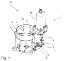
Figure 1 is a simplified perspective view of an example embodiment of an inlet air valve with an example embodiment of an actuating arrangement, -
Figure 2 is a simplified side view of an example embodiment of the inlet air valve with an example embodiment of an actuating arrangement, -
Figure 3 is a simplified side view, of an example embodiment of the inlet air valve with an actuating arrangement, and partly cross-sectional view taken along a line U-U ofFigure 2 , -
Figure 4 is a simplified side view, of an example embodiment of the inlet air valve with an actuating arrangement, and partly cross-sectional view taken along a line A-A ofFigure 3 , -
Figure 5 is a simplified top view, of an example embodiment of the inlet air valve with an actuating arrangement, and partly cross-sectional view taken along a line B-B ofFigure 3 , -
Figure 6 is a simplified side view of an example embodiment of the inlet air valve with an example embodiment of an actuating arrangement in a first position, closing position, -
Figure 6a is a simplified detail C ofFigure 6 , -
Figure 7 is a simplified side view of an example embodiment of the inlet air valve with example embodiment of an actuating arrangement in a second position, open position, -
Figure 7a is a simplified detail D ofFigure 7 , -
Figure 8 is a simplified schematical figure of an example embodiment of an air compressor system of a mining machine, and -
Figure 9 is a diagram showing examples of opening curves of example embodiments of intake air valves. - In the figures, some embodiments are shown simplified for the sake of clarity. Similar parts are marked with the same reference numbers in the figures.
- According to an aspect, an actuator arrangement for an inlet valve for a compressor device described in this description may be arranged in a mobile mining machine. The machine may be a mine machine, or a construction machine, e.g., a rock drilling rig, a development drill, a tunneling drilling machine, a surface drilling machine, a bolting or reinforcing vehicle, a rock removal machine, a longhole drill rig, an explosive charging machine, a loader, a transport vehicle, a loading or hauling machine, a setting vehicle of gallery arcs or nets, a concrete spraying machine, a crusher, or a measuring vehicle.
- In
figure 1 theinlet air valve 20 is for simplicity presented without a cover arrangement for the inlet air valve actuator arrangement. - The
inlet air valve 20 may comprise avalve body 2. Theinlet air valve 20 may comprise aflow channel 30 arranged through thevalve body 2. Theinlet air valve 20 may further comprise aclosing element 3 arranged in theflow channel 30. Theclosing element 3 may be arranged movably in theflow channel 30 between at least two positions, a first, closing position, in which theflow channel 30 is closed, and a second, open position, in which air may flow through the channel. In an example embodiment theclosing element 4 may be arranged on ashaft 4 that is arranged cross theflow channel 30 and extending through the wall of the flow channel. Theinlet air valve 20 may comprise anactuator arrangement 1. - In an example embodiment the
inlet air valve 20 may be an adjustable inlet air valve. In an example embodiment theinlet air valve 20 may be an inlet butterfly valve, comprising a disc-like closing element 3. Theinlet air valve 20 may be biased by a spring to be in a default state of closed. Theactuator arrangement 1 may be disposed to adjust the inlet air valve to open an adjustable amount to change an amount of air that can flow to the air inlet of the air compressor. In example embodiments theinlet air valve 20 may be operated by an electrical, hydraulic, or pneumatic actuator arrangement in communication with the controller. In example embodiments theactuator arrangement 1 may be in electrical communication with the controller. In an example embodiment the compressor system may comprise apressure sensor 27. The pressure sensor may be a transducer for converting pressure into an electrical signal. The pressure sensor may be in electrical communication with the controller. The pressure sensor may be located in or near the air compressor. The engine may be an electric engine or a gasoline motor or a hydraulic motor. The air compressor may be a screw air compressor. The air inlet of the air compressor may be an air inlet of the air compressor. The air outlet of the air compressor may be an air outlet of the air compressor. Thecontroller 50 may be a programmable logic controller (PLC). The controller may be in electrical communication with theactuator 21 of theinlet air valve 20. In an example embodiment theactuator arrangement 1 may be the actuator or part of the actuator. Thecontroller 50 may be in electrical communication with the sensors. Thecontroller 50 may be configured to control the operation of the air compressor system. -
Figures 1 to 5 illustrates an example embodiment of theinlet air valve 20 comprising anactuator arrangement 1 for an inlet air valve. In an example embodiment the inlet air valve may be a type of a butterfly valve. The closing means may be arranged on ashaft 4 that may be arranged rotatably on a valve body cross theflow channel 30. An end of theshaft 4 may extend through a wall of the valve body defining theflow channel 30. Theactuator arrangement 1 may comprise alinear actuator 11 comprising amovable element 10. Themovable element 10 of thelinear actuator 11 may be operatively connected via alever mechanism shaft 4 of theclosing element 3 of the inlet air valve. A linear movement of themovable element 10 of thelinear actuator 11 may be transmitted via thelever mechanism shaft 4 of theclosing element 3 of the inlet air valve. In an example embodiment a transmission ratio of the lever mechanism is configured to vary during a movement of themovable element 10 of thelinear actuator 11. In an example embodiment offigure 1 the inlet air valve is in a closed state. In an example embodiment offigures 2 to 5 the inlet air valve is in an open state. - In an example embodiment the
shaft 4 of theclosing element 3 of the inlet air valve is rotatable by thelever mechanism closing element 3. - In an example embodiment the
lever mechanism first lever 6. The first lever may comprise a firstconnecting point 5 and a secondconnecting point 7. Thefirst lever 6 may be connected in the first connectingpoint 5 to theshaft 4 of theclosing element 3 of the inlet air valve. The actuating arrangement may further comprise asecond lever 8, comprising a first connecting point and a second connecting point. The first connecting point of thesecond lever 8 may be pivotally connected to thefirst lever 6 in the secondconnecting point 7 arranged at a distance from thefirst connection point 5. The secondconnecting point 9 of thesecond lever 8 may be pivotally connected directly or via a further lever, to themovable element 10. The linear movement of themovable element 10 of thelinear actuator 11 may be transmitted via thelever mechanism shaft 4 of theclosing element 3. - In an example embodiment a distance between the connecting
points second lever 8 may be adjustable. Thesecond lever 8 may be, for example, a turnbuckle type of a lever. - The movement of the
movable element 10 of themovable element 10 of thelinear actuator 11 may be transmitted progressively via thelever mechanism shaft 4 of the closing element (3) of the inlet air valve. - In an example embodiment the
linear actuator 11 may be fastened on aframe portion 31 through which theshaft 4 of theclosing element 3 is extending. Thelever mechanism frame portion 31 that is away from theflow channel 30. - In an example embodiment of
figures 6, 6a, 7, 7a thelever mechanism third lever 91 arranged between thesecond lever 8 and themovable element 10 of thelinear actuator 11. - The
third lever 91 may be pivotally connected in a first connection point to a secondconnecting point 9 of thesecond lever 8 and pivotally connected in a second connection point to themovable element 10 of thelinear actuator 11. The second connecting point may be at a distance from the first connecting point. - In an example embodiment a
fourth lever 81 may be arranged to connect thethird lever 91 to aframe portion 31, wherein a first connecting point of thefourth lever 81 is pivotally connected to theframe 31, and a second connecting point of thefourth lever 81 is connected to thethird lever 91 between the first connecting point and the second connecting point. In an example embodiment the lever mechanism is a four link mechanism. - In an example embodiment a connection point between the
first lever 6 and thesecond lever 8 may be a movable point in relation to the position of the second connecting point of the first lever. In an example embodiment the movable point may be a roll arranged on a second end of the first lever and arranged to move on a path formed on the second lever. - In an example embodiment the
linear actuator 11 may be a hydraulic actuator or a pneumatic actuator or an electric actuator or an electro-hydraulic actuator, comprising a cylinder and a piston, and a bias element arranged in the actuator for assisting to return the movable element of the linear actuator and the valve element to a closing position. - The air flows through the filter, through the inlet air valve (when it is open), and into the air compressor. The inlet air valve may be in a default position of closed. A bias element (such as a spring, not illustrated) may hold the inlet air valve closed. The
linear actuator 11 may be connected to the inlet air valve and the controller. The linear actuator may respond to current from the controller by extending the linear actuator. The movable element of the linear actuator pushes on the closing element of the inlet air valve which moves the inlet air valve to an open position. The inlet air valve may be adjustable so that the size of the opening of the inlet air valve is proportional to the amount themovable element 10 of thelinear actuator 11 pushes on the closing element of the inlet air valve. In an example embodiment the movement of themovable element 10 of thelinear actuator 11 may be transmitted progressively via thelever mechanism shaft 4 of theclosing element 3 of the inlet air valve. -
Figure 8 shows an example embodiment of an air compressor system of amining machine 100. Air flows through theair filter 24 and is filtered by the air filter. The air flows through theinlet air valve 20, which may be configured to control the amount of air that can flow through the adjustableinlet air valve 20. Thecontroller 50 may control how open the adjustableinlet air valve 20 is by providing signal or impulse theactuator arrangement 21. By adjusting the adjustableinlet air valve 20 thecontroller 50 can control the volume of compressed air delivered by theair compressor 22. This may be called throttling the air compressor system by controlling the opening of the adjustableinlet air valve 20. - The air that flows through the adjustable
inlet air valve 20 flows into theair inlet 25 of theair compressor 22 and is compressed by the air compressor, which delivers a volume of compressed air to theair outlet 26 of the air compressor. Theair compressor 22 may be driven by theengine 23. In an example embodiment the air compressor system may be a part ofmobile mining machine 100. -
Figure 9 is a diagram showing examples of opening curves of example embodiments of intake air valves. In thefigure 9 is presented on a vertical axis (Y-axis) a size of an opening of a flow channel converted to circular openings having different diameters in mm. In an example embodiment the flow channel may have a nominal diameter of 150 mm. In an example embodiment a flow area (or a size of an opening of a flow channel) may be converted to circular opening diameters, in figure from 0 mm to 150 mm. On a horizontal axis (X-axis) is presented movement of a moving element of a linear actuator in percentages, 0% to 100%. The percentage is 0% when the moving element is a first position. The percentage increases according to the movement of the movable element of the linear actuator. The percentage is 100% when the moving element is a second position, i.e. in an extended position. - When the percentage of movement of the moving element of the linear actuator increases the opening of the flow channel becomes larger due the movement of the linear actuator transmitted by the lever mechanism to the closing element from closing position towards fully open position of the inlet air valve.
- In the prior art version (Prior art) the opening curve seems to be linear. In exemplary embodiments of the different inlet air valve versions (Ver1, Ver2, Ver3) with different actuator arrangements the opening curves seem to be clearly non-linear. Ver1 may be an exemplary embodiment of an inlet air valve as shown in
figure 1 . Ver2 may be an exemplary embodiment of an inlet air valve as shown infigure 6 . Ver3 may be an exemplary embodiment of an inlet air valve comprising an actuator arrangement in which a connection point between the first lever and the second lever may be a movable point in relation to the position of the second connecting point of the first lever. In an example embodiment the movable point may be a roll arranged on a second end of the first lever and arranged to move on a path formed on the second lever. In an exemplary embodiments of each of exemplary embodiments Ver1, Ver2, or Ver3 the movement of the closing member of the inlet air valve may be slow in the beginning of movement of the closing member from a closing position towards a fully open position. This may enable an accurate control of inlet air valve, also at small flow channel opening values. - In an example embodiment the
frame portion 31 may be a plate like element, with an upper wall and a lower wall and a side wall connecting the upper wall to the lower wall. In an example embodiment of the inlet air valve may be configured to have an integrated design comprising an actuator arrangement and valve in a same assembly. - In an example embodiment of a
mobile mining machine 100 may comprise at least one at least one air compressor system for producing working air, such as flushing air for a drilling rig operation, wherein the air compressor system of the mining machine comprises aninlet air valve 20 according. - It is obvious to a person skilled in the art that with the advancement of technology, the basic idea of the invention may be implemented in various ways. The invention and its embodiments are thus not limited to the examples described above, instead they may vary within the scope of the claims.
Claims (15)
- An actuator arrangement (1) for an inlet air valve of a compressor system of a mining machine, the actuator arrangement comprises a linear actuator (11) comprising a movable element (10), operatively connected via a lever mechanism (6, 7, 8, 9; 6, 7, 8, 9, 91, 92) to a shaft (4) of a closing element (3) of the inlet air valve, wherein a linear movement of the movable element (10) of the linear actuator (11) is transmitted via the lever mechanism to a rotation movement of the shaft (4) of the closing element (3) of the inlet air valve, wherein a transmission ratio of the lever mechanism is configured to vary during a movement of the movable element (10) of the linear actuator (11).
- The arrangement according to claim 1, wherein the movement of the movable element (10) of the linear actuator (11) is transmitted progressively via the lever mechanism (6, 7, 8, 9; 6, 7, 8, 9, 91, 92) to the shaft (4) of the closing element (3) of the inlet air valve.
- The arrangement according to claim 1 or 2, wherein the shaft (4) of the closing element (3) of the inlet air valve is rotatable by the lever mechanism (6, 7, 8, 9; 6, 7, 8, 9, 91, 92) at an angle (α) formed between a closing position, and a fully open position of the closing element (3).
- The arrangement according to any one of claims 1 to 3, wherein the transmission ratio of the lever mechanism (6, 7, 8, 9; 6, 7, 8, 9, 91, 92) is configurated to vary during the movement of the movable element (10) of the linear actuator (11) so that in the beginning of the movement of the closing element from the closing position of the closing element (3) towards fully open position of the closing element the transmission ratio of the lever mechanism is low so that a movement speed of the closing element (3) has a first, slow, speed, and wherein the transmission ratio of the lever mechanism is configured to increase so that the speed of the movement of the closing element (3) increases during movement of the closing element towards the fully open position.
- The arrangement according to any one of claims 1 to 4, wherein the rotation of the shaft (4) of the closing element (3) is configured to change non-linearly by the lever mechanism (6, 7, 8, 9; 6, 7, 8, 9, 91, 92) in relation to the movement of the movable element (10) of the linear actuator (11).
- The arrangement according to any one of claims 1 to 5, wherein the linear actuator (11) is fastened on a frame portion (31) through which the shaft (4) of the closing element (3) is extending, and that the lever mechanism (6, 7, 8, 9; 6, 7, 8, 9, 91, 92) is arranged on a side of the frame portion (31) that is away from the flow channel (30).
- The arrangement according to any one of claims 1 to 6, wherein the lever mechanism (6, 7, 8, 9; 6, 7, 8, 9, 91, 92) comprises a first lever (6), comprising a first connecting point (5) and a second connecting point (7), wherein the first lever (6) is connected in the first connecting point (5) to the shaft (4) of the closing element (3) of the inlet air valve, and the actuating arrangement further comprises a second lever (8), comprising a first connecting point and a second connecting point, wherein the first connecting point of the second lever (8) is pivotally connected to the first lever in the second connecting point (7) arranged at a distance from the first connection point (5), wherein the second connecting point (9) of the second lever (8) is pivotally connected directly or via a further lever, to the movable element (10), wherein linear movement of the movable element (10) of the linear actuator is transmitted via the lever mechanism (6, 7, 8, 9; 6, 7, 8, 9, 91, 92) to rotation movement of the shaft (4) of the closing element (3).
- The arrangement according to any one of claims 1 to 7, wherein a distance between the connecting points (7, 9) of the second lever (8) is adjustable, wherein the second lever is, for example, a turnbuckle type of a lever.
- The arrangement according to any one of claims 1 to 8, wherein the lever mechanism (6, 7, 8, 9; 6, 7, 8, 9, 91, 92) comprises a third lever (91) arranged between the second lever (8) and the movable element (10) of the linear actuator (11).
- The arrangement according to claim 9, wherein the third lever (91) is pivotally connected in a first connection point to a second connecting point (9) of the second lever (8) and pivotally connected in a second connection point to the movable element (10) of the linear actuator (11), wherein the second connecting point is at a distance from the first connecting point.
- The arrangement according to claim 9 or 10, wherein a fourth lever (81) is arranged to connect the third lever (91) to a frame portion (31), wherein a first connecting point of the fourth lever (81) is pivotally connected to the frame (31), and a second connecting point of the fourth lever (81) is connected to the third lever between the first connecting point and the second connecting point, wherein the lever mechanism is a four link mechanism.
- The arrangement according to any one of claims 1 to 11, wherein a connection point between the first lever (6) and the second lever (8) is a movable point in relation to the position of the second connecting point of the first lever.
- The arrangement according to any one of claims 1 to 12, wherein the linear actuator (11) is a hydraulic actuator or a pneumatic actuator or an electric actuator or an electro-hydraulic actuator, comprising a cylinder and a piston, and a bias element arranged in the actuator for assisting to return the movable element of the linear actuator and the valve element to a closing position.
- An inlet air valve (20) comprising a valve body (2), a flow channel (30) through the valve body, a closing element (3) arranged in the flow channel, said closing element is arranged movably in the flow channel between at least two positions, a first, closing position, in which the flow channel (30) is closed, and a second, open position, in which air may flow through the channel, wherein the inlet air valve comprises a actuator arrangement (1) according to any one of claims 1 to 13.
- A mining machine (100) comprising at least one air compressor system for producing working air, such as flushing air for a drilling rig operation, wherein the air compressor system of the mining machine comprises an inlet air valve (20) according to claim 14.
Priority Applications (4)
| Application Number | Priority Date | Filing Date | Title |
|---|---|---|---|
| EP23182691.8A EP4484749B1 (en) | 2023-06-30 | 2023-06-30 | An actuator arrangement for an inlet air valve of a compressor, an inlet air valve, and a mining machine |
| JP2025575847A JP2026523224A (en) | 2023-06-30 | 2024-06-17 | Actuator device for compressor intake valve, intake valve, and mining machine |
| AU2024309502A AU2024309502A1 (en) | 2023-06-30 | 2024-06-17 | An actuator arrangement for an inlet air valve of a compressor, an inlet air valve, and a mining machine |
| PCT/EP2024/066856 WO2025002889A1 (en) | 2023-06-30 | 2024-06-17 | An actuator arrangement for an inlet air valve of a compressor, an inlet air valve, and a mining machine |
Applications Claiming Priority (1)
| Application Number | Priority Date | Filing Date | Title |
|---|---|---|---|
| EP23182691.8A EP4484749B1 (en) | 2023-06-30 | 2023-06-30 | An actuator arrangement for an inlet air valve of a compressor, an inlet air valve, and a mining machine |
Publications (3)
| Publication Number | Publication Date |
|---|---|
| EP4484749A1 true EP4484749A1 (en) | 2025-01-01 |
| EP4484749C0 EP4484749C0 (en) | 2025-12-17 |
| EP4484749B1 EP4484749B1 (en) | 2025-12-17 |
Family
ID=87060244
Family Applications (1)
| Application Number | Title | Priority Date | Filing Date |
|---|---|---|---|
| EP23182691.8A Active EP4484749B1 (en) | 2023-06-30 | 2023-06-30 | An actuator arrangement for an inlet air valve of a compressor, an inlet air valve, and a mining machine |
Country Status (4)
| Country | Link |
|---|---|
| EP (1) | EP4484749B1 (en) |
| JP (1) | JP2026523224A (en) |
| AU (1) | AU2024309502A1 (en) |
| WO (1) | WO2025002889A1 (en) |
Families Citing this family (1)
| Publication number | Priority date | Publication date | Assignee | Title |
|---|---|---|---|---|
| CN119900829B (en) * | 2025-03-26 | 2026-01-09 | 浙江东开半导体科技有限公司 | Pneumatic air valve and device |
Citations (5)
| Publication number | Priority date | Publication date | Assignee | Title |
|---|---|---|---|---|
| US2600499A (en) * | 1948-09-25 | 1952-06-17 | Everlasting Valve Co | Swinging gate valve mechanism |
| US2991002A (en) * | 1956-03-21 | 1961-07-04 | Chicago Pneumatic Tool Co | Installations for compressing air or gas |
| US3317179A (en) * | 1963-08-09 | 1967-05-02 | David F Wiseman & Sons Ltd | Valve operating linkages |
| US4134619A (en) * | 1977-09-15 | 1979-01-16 | Fmc Corporation | Subterranean mining |
| US20020108659A1 (en) * | 2001-02-12 | 2002-08-15 | Horvath Josef M. | Device for controlling the output of rotary compressors |
-
2023
- 2023-06-30 EP EP23182691.8A patent/EP4484749B1/en active Active
-
2024
- 2024-06-17 WO PCT/EP2024/066856 patent/WO2025002889A1/en not_active Ceased
- 2024-06-17 JP JP2025575847A patent/JP2026523224A/en active Pending
- 2024-06-17 AU AU2024309502A patent/AU2024309502A1/en active Pending
Patent Citations (5)
| Publication number | Priority date | Publication date | Assignee | Title |
|---|---|---|---|---|
| US2600499A (en) * | 1948-09-25 | 1952-06-17 | Everlasting Valve Co | Swinging gate valve mechanism |
| US2991002A (en) * | 1956-03-21 | 1961-07-04 | Chicago Pneumatic Tool Co | Installations for compressing air or gas |
| US3317179A (en) * | 1963-08-09 | 1967-05-02 | David F Wiseman & Sons Ltd | Valve operating linkages |
| US4134619A (en) * | 1977-09-15 | 1979-01-16 | Fmc Corporation | Subterranean mining |
| US20020108659A1 (en) * | 2001-02-12 | 2002-08-15 | Horvath Josef M. | Device for controlling the output of rotary compressors |
Also Published As
| Publication number | Publication date |
|---|---|
| EP4484749C0 (en) | 2025-12-17 |
| JP2026523224A (en) | 2026-07-13 |
| WO2025002889A1 (en) | 2025-01-02 |
| EP4484749B1 (en) | 2025-12-17 |
| AU2024309502A1 (en) | 2025-11-20 |
Similar Documents
| Publication | Publication Date | Title |
|---|---|---|
| AU2004202818B2 (en) | Control system for pneumatically-powered door installation | |
| CN101874183B (en) | Improved Air Regulator | |
| JP2582266B2 (en) | Fluid pressure control system | |
| EP4484749B1 (en) | An actuator arrangement for an inlet air valve of a compressor, an inlet air valve, and a mining machine | |
| CN101952517A (en) | Interference prevention control device for operating machinery | |
| EP1068932A2 (en) | Valve and position control system integrable with clamp | |
| EP2090496A1 (en) | Bending construction vehicle | |
| BR112012027716B1 (en) | PUMP CONTROL SET AND METHOD FOR ACTING A PUMP CONTROL SET | |
| EP2446150B1 (en) | Valve device | |
| US5678642A (en) | Drilling arrangement and drilling feed mechanism | |
| US6732629B1 (en) | Pneumatic actuator circuit | |
| RU2646244C2 (en) | Air flow system for mining machine | |
| AU2020202150B2 (en) | Control system for drilling machines | |
| US12584295B2 (en) | Work machine | |
| KR102201181B1 (en) | Apparatus for automatically adjusting the amount of opening and closing of damper | |
| EP0010557B1 (en) | Apparatus for safeguarding transport of a suspension of dredging spoil and water | |
| KR20160074866A (en) | Hydraulic system for construction equipment and control method for there of | |
| CN209457931U (en) | A kind of mechanical structure of the instruction sending system of petroleum orientation device | |
| JPH0726562Y2 (en) | Hydraulic actuator drive | |
| US20050000350A1 (en) | Actuator cylinder | |
| JP2023049997A5 (en) | ||
| JP2026079940A (en) | Hydraulic system of a hydraulic crusher | |
| RU2019102201A (en) | WORKING MACHINE WITH HYDRAULICS FOR ENERGY RECOVERY | |
| KR20000021947A (en) | Regulator of hydraulic pressure operation body for heavy equipment vehicle |
Legal Events
| Date | Code | Title | Description |
|---|---|---|---|
| PUAI | Public reference made under article 153(3) epc to a published international application that has entered the european phase |
Free format text: ORIGINAL CODE: 0009012 |
|
| STAA | Information on the status of an ep patent application or granted ep patent |
Free format text: STATUS: THE APPLICATION HAS BEEN PUBLISHED |
|
| AK | Designated contracting states |
Kind code of ref document: A1 Designated state(s): AL AT BE BG CH CY CZ DE DK EE ES FI FR GB GR HR HU IE IS IT LI LT LU LV MC ME MK MT NL NO PL PT RO RS SE SI SK SM TR |
|
| STAA | Information on the status of an ep patent application or granted ep patent |
Free format text: STATUS: REQUEST FOR EXAMINATION WAS MADE |
|
| 17P | Request for examination filed |
Effective date: 20250701 |
|
| GRAP | Despatch of communication of intention to grant a patent |
Free format text: ORIGINAL CODE: EPIDOSNIGR1 |
|
| STAA | Information on the status of an ep patent application or granted ep patent |
Free format text: STATUS: GRANT OF PATENT IS INTENDED |
|
| RIC1 | Information provided on ipc code assigned before grant |
Ipc: F04B 39/10 20060101AFI20250821BHEP Ipc: F04B 49/22 20060101ALI20250821BHEP Ipc: F16K 3/04 20060101ALI20250821BHEP Ipc: F16K 3/06 20060101ALI20250821BHEP Ipc: F16K 1/22 20060101ALI20250821BHEP Ipc: F16K 31/163 20060101ALI20250821BHEP Ipc: F16K 31/52 20060101ALI20250821BHEP |
|
| INTG | Intention to grant announced |
Effective date: 20250915 |
|
| GRAS | Grant fee paid |
Free format text: ORIGINAL CODE: EPIDOSNIGR3 |
|
| GRAA | (expected) grant |
Free format text: ORIGINAL CODE: 0009210 |
|
| STAA | Information on the status of an ep patent application or granted ep patent |
Free format text: STATUS: THE PATENT HAS BEEN GRANTED |
|
| AK | Designated contracting states |
Kind code of ref document: B1 Designated state(s): AL AT BE BG CH CY CZ DE DK EE ES FI FR GB GR HR HU IE IS IT LI LT LU LV MC ME MK MT NL NO PL PT RO RS SE SI SK SM TR |
|
| REG | Reference to a national code |
Ref country code: CH Ref legal event code: F10 Free format text: ST27 STATUS EVENT CODE: U-0-0-F10-F00 (AS PROVIDED BY THE NATIONAL OFFICE) Effective date: 20251217 Ref country code: GB Ref legal event code: FG4D |
|
| REG | Reference to a national code |
Ref country code: DE Ref legal event code: R096 Ref document number: 602023009742 Country of ref document: DE |
|
| U01 | Request for unitary effect filed |
Effective date: 20251217 |
|
| U07 | Unitary effect registered |
Designated state(s): AT BE BG DE DK EE FI FR IT LT LU LV MT NL PT RO SE SI Effective date: 20251223 |
|
| PG25 | Lapsed in a contracting state [announced via postgrant information from national office to epo] |
Ref country code: NO Free format text: LAPSE BECAUSE OF FAILURE TO SUBMIT A TRANSLATION OF THE DESCRIPTION OR TO PAY THE FEE WITHIN THE PRESCRIBED TIME-LIMIT Effective date: 20260317 |
|
| PG25 | Lapsed in a contracting state [announced via postgrant information from national office to epo] |
Ref country code: HR Free format text: LAPSE BECAUSE OF FAILURE TO SUBMIT A TRANSLATION OF THE DESCRIPTION OR TO PAY THE FEE WITHIN THE PRESCRIBED TIME-LIMIT Effective date: 20251217 |
|
| PG25 | Lapsed in a contracting state [announced via postgrant information from national office to epo] |
Ref country code: RS Free format text: LAPSE BECAUSE OF FAILURE TO SUBMIT A TRANSLATION OF THE DESCRIPTION OR TO PAY THE FEE WITHIN THE PRESCRIBED TIME-LIMIT Effective date: 20260317 |
|
| PG25 | Lapsed in a contracting state [announced via postgrant information from national office to epo] |
Ref country code: SM Free format text: LAPSE BECAUSE OF FAILURE TO SUBMIT A TRANSLATION OF THE DESCRIPTION OR TO PAY THE FEE WITHIN THE PRESCRIBED TIME-LIMIT Effective date: 20251217 |
|
| PG25 | Lapsed in a contracting state [announced via postgrant information from national office to epo] |
Ref country code: ES Free format text: LAPSE BECAUSE OF FAILURE TO SUBMIT A TRANSLATION OF THE DESCRIPTION OR TO PAY THE FEE WITHIN THE PRESCRIBED TIME-LIMIT Effective date: 20251217 |
|
| PG25 | Lapsed in a contracting state [announced via postgrant information from national office to epo] |
Ref country code: PL Free format text: LAPSE BECAUSE OF FAILURE TO SUBMIT A TRANSLATION OF THE DESCRIPTION OR TO PAY THE FEE WITHIN THE PRESCRIBED TIME-LIMIT Effective date: 20251217 |
|
| PG25 | Lapsed in a contracting state [announced via postgrant information from national office to epo] |
Ref country code: IS Free format text: LAPSE BECAUSE OF FAILURE TO SUBMIT A TRANSLATION OF THE DESCRIPTION OR TO PAY THE FEE WITHIN THE PRESCRIBED TIME-LIMIT Effective date: 20260417 |
|
| PG25 | Lapsed in a contracting state [announced via postgrant information from national office to epo] |
Ref country code: CZ Free format text: LAPSE BECAUSE OF FAILURE TO SUBMIT A TRANSLATION OF THE DESCRIPTION OR TO PAY THE FEE WITHIN THE PRESCRIBED TIME-LIMIT Effective date: 20251217 |
|
| PG25 | Lapsed in a contracting state [announced via postgrant information from national office to epo] |
Ref country code: SK Free format text: LAPSE BECAUSE OF FAILURE TO SUBMIT A TRANSLATION OF THE DESCRIPTION OR TO PAY THE FEE WITHIN THE PRESCRIBED TIME-LIMIT Effective date: 20251217 |
|
| U20 | Renewal fee for the european patent with unitary effect paid |
Year of fee payment: 4 Effective date: 20260630 |