EP4484716A1 - Systems for vane pitch actuation - Google Patents
Systems for vane pitch actuation Download PDFInfo
- Publication number
- EP4484716A1 EP4484716A1 EP24182922.5A EP24182922A EP4484716A1 EP 4484716 A1 EP4484716 A1 EP 4484716A1 EP 24182922 A EP24182922 A EP 24182922A EP 4484716 A1 EP4484716 A1 EP 4484716A1
- Authority
- EP
- European Patent Office
- Prior art keywords
- sync ring
- gear teeth
- axis
- electric motor
- recited
- Prior art date
- Legal status (The legal status is an assumption and is not a legal conclusion. Google has not performed a legal analysis and makes no representation as to the accuracy of the status listed.)
- Pending
Links
Images


Classifications
-
- F—MECHANICAL ENGINEERING; LIGHTING; HEATING; WEAPONS; BLASTING
- F01—MACHINES OR ENGINES IN GENERAL; ENGINE PLANTS IN GENERAL; STEAM ENGINES
- F01D—NON-POSITIVE DISPLACEMENT MACHINES OR ENGINES, e.g. STEAM TURBINES
- F01D17/00—Regulating or controlling by varying flow
- F01D17/10—Final actuators
- F01D17/12—Final actuators arranged in stator parts
- F01D17/14—Final actuators arranged in stator parts varying effective cross-sectional area of nozzles or guide conduits
- F01D17/16—Final actuators arranged in stator parts varying effective cross-sectional area of nozzles or guide conduits by means of nozzle vanes
- F01D17/162—Final actuators arranged in stator parts varying effective cross-sectional area of nozzles or guide conduits by means of nozzle vanes for axial flow, i.e. the vanes turning around axes which are essentially perpendicular to the rotor centre line
-
- F—MECHANICAL ENGINEERING; LIGHTING; HEATING; WEAPONS; BLASTING
- F01—MACHINES OR ENGINES IN GENERAL; ENGINE PLANTS IN GENERAL; STEAM ENGINES
- F01D—NON-POSITIVE DISPLACEMENT MACHINES OR ENGINES, e.g. STEAM TURBINES
- F01D9/00—Stators
- F01D9/02—Nozzles; Nozzle boxes; Stator blades; Guide conduits, e.g. individual nozzles
- F01D9/04—Nozzles; Nozzle boxes; Stator blades; Guide conduits, e.g. individual nozzles forming ring or sector
- F01D9/041—Nozzles; Nozzle boxes; Stator blades; Guide conduits, e.g. individual nozzles forming ring or sector using blades
-
- F—MECHANICAL ENGINEERING; LIGHTING; HEATING; WEAPONS; BLASTING
- F01—MACHINES OR ENGINES IN GENERAL; ENGINE PLANTS IN GENERAL; STEAM ENGINES
- F01D—NON-POSITIVE DISPLACEMENT MACHINES OR ENGINES, e.g. STEAM TURBINES
- F01D17/00—Regulating or controlling by varying flow
- F01D17/20—Devices dealing with sensing elements or final actuators or transmitting means between them, e.g. power-assisted
- F01D17/22—Devices dealing with sensing elements or final actuators or transmitting means between them, e.g. power-assisted the operation or power assistance being predominantly non-mechanical
- F01D17/24—Devices dealing with sensing elements or final actuators or transmitting means between them, e.g. power-assisted the operation or power assistance being predominantly non-mechanical electrical
-
- F—MECHANICAL ENGINEERING; LIGHTING; HEATING; WEAPONS; BLASTING
- F05—INDEXING SCHEMES RELATING TO ENGINES OR PUMPS IN VARIOUS SUBCLASSES OF CLASSES F01-F04
- F05D—INDEXING SCHEME FOR ASPECTS RELATING TO NON-POSITIVE-DISPLACEMENT MACHINES OR ENGINES, GAS-TURBINES OR JET-PROPULSION PLANTS
- F05D2260/00—Function
- F05D2260/40—Transmission of power
- F05D2260/403—Transmission of power through the shape of the drive components
- F05D2260/4031—Transmission of power through the shape of the drive components as in toothed gearing
-
- F—MECHANICAL ENGINEERING; LIGHTING; HEATING; WEAPONS; BLASTING
- F05—INDEXING SCHEMES RELATING TO ENGINES OR PUMPS IN VARIOUS SUBCLASSES OF CLASSES F01-F04
- F05D—INDEXING SCHEME FOR ASPECTS RELATING TO NON-POSITIVE-DISPLACEMENT MACHINES OR ENGINES, GAS-TURBINES OR JET-PROPULSION PLANTS
- F05D2260/00—Function
- F05D2260/70—Adjusting of angle of incidence or attack of rotating blades
- F05D2260/74—Adjusting of angle of incidence or attack of rotating blades by turning around an axis perpendicular the rotor centre line
-
- F—MECHANICAL ENGINEERING; LIGHTING; HEATING; WEAPONS; BLASTING
- F05—INDEXING SCHEMES RELATING TO ENGINES OR PUMPS IN VARIOUS SUBCLASSES OF CLASSES F01-F04
- F05D—INDEXING SCHEME FOR ASPECTS RELATING TO NON-POSITIVE-DISPLACEMENT MACHINES OR ENGINES, GAS-TURBINES OR JET-PROPULSION PLANTS
- F05D2260/00—Function
- F05D2260/70—Adjusting of angle of incidence or attack of rotating blades
- F05D2260/79—Bearing, support or actuation arrangements therefor
-
- F—MECHANICAL ENGINEERING; LIGHTING; HEATING; WEAPONS; BLASTING
- F05—INDEXING SCHEMES RELATING TO ENGINES OR PUMPS IN VARIOUS SUBCLASSES OF CLASSES F01-F04
- F05D—INDEXING SCHEME FOR ASPECTS RELATING TO NON-POSITIVE-DISPLACEMENT MACHINES OR ENGINES, GAS-TURBINES OR JET-PROPULSION PLANTS
- F05D2270/00—Control
- F05D2270/60—Control system actuates means
- F05D2270/62—Electrical actuators
Definitions
- the present disclosure relates to variable pitch stator vanes, and more particularly to actuation of variable pitch stator vanes in gas turbine engines.
- Variable pitch stator vanes are actuated to adapt an engine to the various engine operating conditions for power and efficiency.
- Traditional stator actuation schemes are hydraulic, e.g. using fuel from the fuel system as the hydraulic fluid, comprising a high-pressure pump, lines, and hydraulic cylinder type actuators that act on a sync ring to move all actuators of a stage.
- the traditional actuators are controlled with feedback loops using position feedback, pressure, and engine speed.
- These systems (the pump) can be mechanically driven from the turbine of the engine and have constant parasitic power draw from the engine to function, i.e. even when the variable pitch stator vanes are stationary.
- a system for vane pitch actuation includes an electric motor with a rotary output shaft defining a drive axis.
- a worm shaft as aligned with the drive axis, and is operatively connected to be driven in rotation about the drive axis by the rotary output shaft of the electric motor.
- a sync ring is defined about an engine axis that is orthogonal to the drive axis. The sync ring is configured to rotate about the engine axis over a range of positions for driving a plurality of variable pitch stator vanes to each have a pitch based on position of the sync ring.
- the sync ring includes a plurality of worm wheel gear teeth engaged to one or more worm gear teeth of the worm shaft for actuation of the sync ring by the electric motor.
- the worm wheel gear teeth can be defined on a forward facing surface of the sync ring relative to the engine axis.
- the worm wheel gear teeth can be defined on an aft facing surface of the sync ring relative to the engine axis.
- the worm wheel gear teeth can be defined on a radially outward facing surface of the sync ring relative to the engine axis.
- a plurality of vane linkages can be connected to the sync ring, each for rotating pitch of one of the plurality of variable pitch stator vanes.
- the plurality of variable pitch stator vanes can be each operatively connected to a respective one of the plurality of vane linkages for rotating pitch.
- the gas turbine engine can be included, defined along the engine axis.
- the gas turbine engine can include an inner case defining a gas path, wherein the plurality of variable pitch stator vanes are inside the inner case, in the gas path.
- the worm wheel gear teeth and the one or more worm gear teeth can be outside of the inner case but inside an outer case of the gas turbine engine.
- the electric motor can be outside the outer case.
- At least one of the rotary output shaft and/or the worm shaft can extend through the outer case.
- the worm shaft can be oriented tangent to the sync ring.
- a position resolver can be operatively connected to at least one of the rotary shaft, to the sync ring, and/or to the worm shaft to generate feedback indicative of position of the sync ring.
- a controller can be operatively connected to receive the feedback indicative of position and to control the electric motor based on the feedback.
- a system for vane pitch actuation includes an electric motor with a rotary output shaft defining a drive axis.
- a pinion is aligned with the drive axis, and is operatively connected to be driven in rotation about the drive axis by the rotary output shaft of the electric motor.
- a sync ring is defined about an engine axis that is orthogonal to the drive axis. The sync ring is configured to rotate about the engine axis over a range of positions for driving a plurality of variable pitch stator vanes to each have a pitch based on position of the sync ring.
- the sync ring includes a plurality of rack gear teeth engaged to one or more pinion gear teeth of the pinion for actuation of the sync ring by the electric motor.
- the rack gear teeth can be defined on a forward facing surface of the sync ring relative to the engine axis.
- the rack gear teeth can be defined on an aft facing surface of the sync ring relative to the engine axis.
- the rack gear teeth can be defined on a radially outward facing surface of the sync ring relative to the engine axis.
- a plurality of vane linkages can be connected to the sync ring, each for rotating pitch of one of the plurality of variable pitch stator vanes.
- the plurality of variable pitch stator vanes can be each operatively connected to a respective one of the plurality of vane linkages for rotating pitch.
- the gas turbine engine can be included, defined along the engine axis.
- the gas turbine engine can include an inner case defining a gas path, wherein the plurality of variable pitch stator vanes are inside the inner case, in the gas path.
- the rack gear teeth and the one or more pinion gear teeth can be outside of the inner case but inside an outer case of the gas turbine engine.
- the electric motor can be outside the outer case.
- the rotary output shaft can extend through the outer case.
- the pinion can be oriented radial to the sync ring.
- a position resolver can be operatively connected to at least one of the rotary shaft, to the sync ring, and/or to the pinion to generate feedback indicative of position of the sync ring.
- a controller can be operatively connected to receive the feedback indicative of position and to control the electric motor based on the feedback.
- Fig. 1 a partial view of an embodiment of a system in accordance with the disclosure is shown in Fig. 1 and is designated generally by reference character 100.
- FIGs. 2-4 Other embodiments of systems in accordance with the disclosure, or aspects thereof, are provided in Figs. 2-4 , as will be described.
- the systems and methods described herein can be used to electrically actuate variable pitch vanes, e.g. to reduce power needed to run hydraulic actuation systems that traditionally drive van actuation.
- the gas turbine engine 102 is defined along the engine axis A.
- the gas turbine engine 102 includes an inner case 104 defining a gas path P.
- a plurality of variable pitch stator vanes 106 e.g. in the fan, turbine section, or compressor section of the gas turbine engine 102, are inside the inner case 104, in the gas path P.
- the rotor vanes 107 alternate with the stator vanes 106 in the longitudinal direction along the engine axis A.
- Each variable pitch stator vane 106 can change its angle of attack in the gas path P by rotation about its radial axis ⁇ .
- the system 100 for vane pitch actuation includes an electric motor 108 with a rotary output shaft 110 defining a drive axis B.
- a worm shaft 112 is aligned on the drive axis B, and is operatively connected to be driven in rotation about the drive axis B by the rotary output shaft 110 of the electric motor 108.
- a sync ring 114 is defined about the engine axis that is orthogonal to the drive axis. The sync ring 114 is configured to rotate about the engine axis A over a range of positions, schematically indicated in Fig. 1 by the large double headed arrow, for driving a plurality of the variable pitch stator vanes 106 to each have a pitch based on position of their sync ring 114.
- the sync ring 114 includes a plurality of worm wheel gear teeth 116 engaged to one or more worm gear teeth 118 of the worm shaft for actuation of the sync ring 114 by the electric motor 108.
- the worm wheel gear teeth 118 can be defined on a forward facing surface 120 of the sync ring 114, on an aft facing surface 122 of the sync ring 114, or on the radially outward facing surface 124 of the sync ring 114 relative to the engine axis A.
- a plurality of vane linkages 126 are connected to the sync ring 114, each for rotating pitch of one of the variable pitch stator vanes 106.
- the variable pitch stator vanes 106 are each operatively connected to a respective one of the plurality of vane linkages 126 for rotating pitch.
- the worm wheel gear teeth 116 and the one or more worm gear teeth 118 are outside of the inner case 104 but inside an outer case 128 of the gas turbine engine 102.
- the electric motor 108 is outside the outer case 128.
- At least one of the rotary output shaft 110 and/or the worm shaft 112 extend through the outer case 128.
- the worm shaft 112, and its rotation axis B, is oriented tangent to the sync ring 114, which is defined around the engine axis A.
- a position resolver 130 is operatively connected to at least one of the rotary shaft 110, to the sync ring 114, and/or to the worm shaft 112 to generate feedback indicative of position of the sync ring 114.
- a controller 132 is operatively connected to receive the feedback indicative of position and to control the electric motor 108 based on the feedback.
- each sync ring 114 can be individually actuated, or each sync ring can be connected by a linkage 134 (one of which is indicated in Fig. 1 with broken lines) to the one sync ring 114 that is directly connected to the motor 108 so that all of the sync rings 104 can be actuated together.
- a similar system 100 for vane pitch actuation includes an electric motor 108 with a rotary output shaft 110 defining a drive axis B.
- a pinion 112 defines a drive axis B, and is operatively connected to be driven in rotation about the drive axis B by the rotary output shaft 110 of the electric motor 108.
- a sync ring 114 is defined about an engine axis A as described above for adjusting angle of attack of a plurality of variable pitch stator vanes 114.
- the sync ring 114 includes a plurality of rack gear teeth 116 engaged to one or more pinion gear teeth 118 of the pinion 112 for actuation of the sync ring 114 by the electric motor 108.
- the rack gear teeth 118 can be defined on the forward, aft, or radially outward facing surfaces 120, 124, 122 of the sync ring 114 as long as they mesh with the pinion 112, much as described above with respect to Figs. 1-2 .
- Other aspects of the system 100 in Fig. 3 that are the same as already described above with respect to Figs. 1-2 will not be repeated, but like reference numbers are used in Figs. 3-4 for like components.
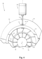
- the rack and pinion configuration of the system 100 is shown in elevation.
- the rack gear teeth 116 and the one or more pinion gear teeth 118 are outside of the inner case 104 but inside the outer case 128 of the gas turbine engine 102.
- the electric motor 108 is outside the outer case 128.
- the rotary output 110 shaft a extends through the outer case 128.
- the pinion 112 by virtue of rotating about the drive axis B, is oriented radial to the sync ring 114 instead of tangent as in the worm drive configuration of Fig. 2 .
- Systems and methods as disclosed herein provide potential benefits including the following. They can remove or substantially reduce the size of the fuel system hydraulic needs of engine actuation system over traditional hydraulically driven sync ring systems. They allow for reduced mechanical part count, reduced envelope, and reduced weight of the vane actuation system compared to more traditional configurations. They can provide for zero parasitic power consumption, e.g., when utilizing non-backfeeding gears. They can also provide improved positional accuracy and reduced hysteresis.
- traditional variable pitch actuation there is an actuator that drives a drive link, that drives a torque box, that drives a drive link, that drives the sync ring, which drives the vane arm.
- the number of pinned/bolted joints is reduced, reducing the overall slop in the linkage, which improves accuracy and reduces hysteresis relative to the traditional configurations.
- variable pitch vanes e.g. to reduce power needed to run hydraulic actuation systems that traditionally drive van actuation.
- apparatus and methods of the subject disclosure have been shown and described with reference to preferred embodiments, those skilled in the art will readily appreciate that changes and/or modifications may be made thereto without departing from the scope of the subject disclosure.
Landscapes
- Engineering & Computer Science (AREA)
- Mechanical Engineering (AREA)
- General Engineering & Computer Science (AREA)
- Connection Of Motors, Electrical Generators, Mechanical Devices, And The Like (AREA)
- Control Of Turbines (AREA)
Abstract
A system for vane pitch actuation includes an electric motor (108) with a rotary output shaft (110) defining a drive axis (B). A worm shaft or a pinion (112) defines a drive axis, and is operatively connected to be driven in rotation about the drive axis by the rotary output shaft of the electric motor. A sync ring (114) is defined about an engine axis (A) that is orthogonal to the drive axis. The sync ring is configured to rotate about the engine axis over a range of positions for driving a plurality of variable pitch stator vanes (106) to each have a pitch based on position of the sync ring. The sync ring includes a plurality of gear teeth (116) for actuation of the sync ring by the electric motor.

Description
- The present disclosure relates to variable pitch stator vanes, and more particularly to actuation of variable pitch stator vanes in gas turbine engines.
- Fans, Compressor sections, and turbine sections in gas turbine engines can include variable pitch stator vanes. Variable pitch stator vanes are actuated to adapt an engine to the various engine operating conditions for power and efficiency. Traditional stator actuation schemes are hydraulic, e.g. using fuel from the fuel system as the hydraulic fluid, comprising a high-pressure pump, lines, and hydraulic cylinder type actuators that act on a sync ring to move all actuators of a stage. The traditional actuators are controlled with feedback loops using position feedback, pressure, and engine speed. These systems (the pump) can be mechanically driven from the turbine of the engine and have constant parasitic power draw from the engine to function, i.e. even when the variable pitch stator vanes are stationary.
- The conventional techniques have been considered satisfactory for their intended purpose. However, there is an ever present need for improved systems and methods for actuating variable pitch stator vanes. This disclosure provides a solution for this need.
- A system for vane pitch actuation includes an electric motor with a rotary output shaft defining a drive axis. A worm shaft as aligned with the drive axis, and is operatively connected to be driven in rotation about the drive axis by the rotary output shaft of the electric motor. A sync ring is defined about an engine axis that is orthogonal to the drive axis. The sync ring is configured to rotate about the engine axis over a range of positions for driving a plurality of variable pitch stator vanes to each have a pitch based on position of the sync ring. The sync ring includes a plurality of worm wheel gear teeth engaged to one or more worm gear teeth of the worm shaft for actuation of the sync ring by the electric motor.
- The worm wheel gear teeth can be defined on a forward facing surface of the sync ring relative to the engine axis. The worm wheel gear teeth can be defined on an aft facing surface of the sync ring relative to the engine axis. The worm wheel gear teeth can be defined on a radially outward facing surface of the sync ring relative to the engine axis.
- A plurality of vane linkages can be connected to the sync ring, each for rotating pitch of one of the plurality of variable pitch stator vanes. The plurality of variable pitch stator vanes can be each operatively connected to a respective one of the plurality of vane linkages for rotating pitch.
- The gas turbine engine can be included, defined along the engine axis. The gas turbine engine can include an inner case defining a gas path, wherein the plurality of variable pitch stator vanes are inside the inner case, in the gas path. The worm wheel gear teeth and the one or more worm gear teeth can be outside of the inner case but inside an outer case of the gas turbine engine. The electric motor can be outside the outer case. At least one of the rotary output shaft and/or the worm shaft can extend through the outer case. The worm shaft can be oriented tangent to the sync ring.
- A position resolver can be operatively connected to at least one of the rotary shaft, to the sync ring, and/or to the worm shaft to generate feedback indicative of position of the sync ring. A controller can be operatively connected to receive the feedback indicative of position and to control the electric motor based on the feedback.
- A system for vane pitch actuation includes an electric motor with a rotary output shaft defining a drive axis. A pinion is aligned with the drive axis, and is operatively connected to be driven in rotation about the drive axis by the rotary output shaft of the electric motor. A sync ring is defined about an engine axis that is orthogonal to the drive axis. The sync ring is configured to rotate about the engine axis over a range of positions for driving a plurality of variable pitch stator vanes to each have a pitch based on position of the sync ring. The sync ring includes a plurality of rack gear teeth engaged to one or more pinion gear teeth of the pinion for actuation of the sync ring by the electric motor.
- The rack gear teeth can be defined on a forward facing surface of the sync ring relative to the engine axis. The rack gear teeth can be defined on an aft facing surface of the sync ring relative to the engine axis. The rack gear teeth can be defined on a radially outward facing surface of the sync ring relative to the engine axis.
- A plurality of vane linkages can be connected to the sync ring, each for rotating pitch of one of the plurality of variable pitch stator vanes. The plurality of variable pitch stator vanes can be each operatively connected to a respective one of the plurality of vane linkages for rotating pitch.
- The gas turbine engine can be included, defined along the engine axis. The gas turbine engine can include an inner case defining a gas path, wherein the plurality of variable pitch stator vanes are inside the inner case, in the gas path. The rack gear teeth and the one or more pinion gear teeth can be outside of the inner case but inside an outer case of the gas turbine engine. The electric motor can be outside the outer case. The rotary output shaft can extend through the outer case. The pinion can be oriented radial to the sync ring.
- A position resolver can be operatively connected to at least one of the rotary shaft, to the sync ring, and/or to the pinion to generate feedback indicative of position of the sync ring. A controller can be operatively connected to receive the feedback indicative of position and to control the electric motor based on the feedback.
- These and other features of the systems and methods of the subject disclosure will become more readily apparent to those skilled in the art from the following detailed description of the preferred embodiments taken in conjunction with the drawings.
- So that those skilled in the art to which the subject disclosure appertains will readily understand how to make and use the devices and methods of the subject disclosure without undue experimentation, preferred embodiments thereof will be described in detail herein below with reference to certain figures, wherein:
-
Fig. 1 is a schematic perspective view of an embodiment of a vane actuation system constructed in accordance with the present disclosure, showing a worm gear configuration for driving the vane actuation electrically; -
Fig. 2 is a schematic axial end elevation view of a portion of the system ofFig. 1 , showing the tangential arrangement of the sync ring and the worm shaft; -
Fig. 3 is a is a schematic perspective view of an embodiment of a vane actuation system constructed in accordance with the present disclosure, showing a rack and pinion configuration for driving the vane actuation electrically; and -
Fig. 4 schematic axial end elevation view of a portion of the system ofFig. 3 , showing the radial arrangement of the pinion relative to the sync ring. - Reference will now be made to the drawings wherein like reference numerals identify similar structural features or aspects of the subject disclosure. For purposes of explanation and illustration, and not limitation, a partial view of an embodiment of a system in accordance with the disclosure is shown in
Fig. 1 and is designated generally byreference character 100. Other embodiments of systems in accordance with the disclosure, or aspects thereof, are provided inFigs. 2-4 , as will be described. The systems and methods described herein can be used to electrically actuate variable pitch vanes, e.g. to reduce power needed to run hydraulic actuation systems that traditionally drive van actuation. - The
gas turbine engine 102 is defined along the engine axis A. Thegas turbine engine 102 includes aninner case 104 defining a gas path P. A plurality of variablepitch stator vanes 106, e.g. in the fan, turbine section, or compressor section of thegas turbine engine 102, are inside theinner case 104, in the gas path P. The rotor vanes 107 alternate with thestator vanes 106 in the longitudinal direction along the engine axis A. Each variablepitch stator vane 106 can change its angle of attack in the gas path P by rotation about its radial axis α. Thesystem 100 for vane pitch actuation includes anelectric motor 108 with arotary output shaft 110 defining a drive axis B.A worm shaft 112 is aligned on the drive axis B, and is operatively connected to be driven in rotation about the drive axis B by therotary output shaft 110 of theelectric motor 108. Async ring 114 is defined about the engine axis that is orthogonal to the drive axis. Thesync ring 114 is configured to rotate about the engine axis A over a range of positions, schematically indicated inFig. 1 by the large double headed arrow, for driving a plurality of the variablepitch stator vanes 106 to each have a pitch based on position of theirsync ring 114. Thesync ring 114 includes a plurality of wormwheel gear teeth 116 engaged to one or moreworm gear teeth 118 of the worm shaft for actuation of thesync ring 114 by theelectric motor 108. The wormwheel gear teeth 118 can be defined on aforward facing surface 120 of thesync ring 114, on anaft facing surface 122 of thesync ring 114, or on the radially outward facingsurface 124 of thesync ring 114 relative to the engine axis A. - A plurality of
vane linkages 126 are connected to thesync ring 114, each for rotating pitch of one of the variable pitch stator vanes 106. The variablepitch stator vanes 106 are each operatively connected to a respective one of the plurality ofvane linkages 126 for rotating pitch. - With reference now to
Fig. 2 , the wormwheel gear teeth 116 and the one or moreworm gear teeth 118 are outside of theinner case 104 but inside anouter case 128 of thegas turbine engine 102. Theelectric motor 108 is outside theouter case 128. At least one of therotary output shaft 110 and/or theworm shaft 112 extend through theouter case 128. Theworm shaft 112, and its rotation axis B, is oriented tangent to thesync ring 114, which is defined around the engine axis A. - With reference again to
Fig. 1 , aposition resolver 130 is operatively connected to at least one of therotary shaft 110, to thesync ring 114, and/or to theworm shaft 112 to generate feedback indicative of position of thesync ring 114. Acontroller 132 is operatively connected to receive the feedback indicative of position and to control theelectric motor 108 based on the feedback. Although inFig. 1 , there is only onesync ring 114 connected to themotor 108, those skilled in the art will readily appreciate that eachsync ring 114 can have its own motor 108 (one of which is indicated inFig. 1 with broken lines) so all of the sync rings 114 can be individually actuated, or each sync ring can be connected by a linkage 134 (one of which is indicated inFig. 1 with broken lines) to the onesync ring 114 that is directly connected to themotor 108 so that all of the sync rings 104 can be actuated together. - With reference now to
Fig. 3 , asimilar system 100 for vane pitch actuation includes anelectric motor 108 with arotary output shaft 110 defining a drive axis B. Apinion 112 defines a drive axis B, and is operatively connected to be driven in rotation about the drive axis B by therotary output shaft 110 of theelectric motor 108. Async ring 114 is defined about an engine axis A as described above for adjusting angle of attack of a plurality of variable pitch stator vanes 114. Thesync ring 114 includes a plurality ofrack gear teeth 116 engaged to one or morepinion gear teeth 118 of thepinion 112 for actuation of thesync ring 114 by theelectric motor 108. Therack gear teeth 118 can be defined on the forward, aft, or radially outward facingsurfaces sync ring 114 as long as they mesh with thepinion 112, much as described above with respect toFigs. 1-2 . Other aspects of thesystem 100 inFig. 3 that are the same as already described above with respect toFigs. 1-2 will not be repeated, but like reference numbers are used inFigs. 3-4 for like components. - With reference to
Fig. 4 , the rack and pinion configuration of thesystem 100 is shown in elevation. Therack gear teeth 116 and the one or morepinion gear teeth 118 are outside of theinner case 104 but inside theouter case 128 of thegas turbine engine 102. Theelectric motor 108 is outside theouter case 128. Therotary output 110 shaft a extends through theouter case 128. Thepinion 112, by virtue of rotating about the drive axis B, is oriented radial to thesync ring 114 instead of tangent as in the worm drive configuration ofFig. 2 . - Systems and methods as disclosed herein provide potential benefits including the following. They can remove or substantially reduce the size of the fuel system hydraulic needs of engine actuation system over traditional hydraulically driven sync ring systems. They allow for reduced mechanical part count, reduced envelope, and reduced weight of the vane actuation system compared to more traditional configurations. They can provide for zero parasitic power consumption, e.g., when utilizing non-backfeeding gears. They can also provide improved positional accuracy and reduced hysteresis. In traditional variable pitch actuation, there is an actuator that drives a drive link, that drives a torque box, that drives a drive link, that drives the sync ring, which drives the vane arm. However, with systems and methods as disclosed herein, the number of pinned/bolted joints is reduced, reducing the overall slop in the linkage, which improves accuracy and reduces hysteresis relative to the traditional configurations.
- The methods and systems of the present disclosure, as described above and shown in the drawings, provide for electrical actuation of variable pitch vanes, e.g. to reduce power needed to run hydraulic actuation systems that traditionally drive van actuation. While the apparatus and methods of the subject disclosure have been shown and described with reference to preferred embodiments, those skilled in the art will readily appreciate that changes and/or modifications may be made thereto without departing from the scope of the subject disclosure.
Claims (15)
- A system for vane pitch actuation comprising:an electric motor (108) with a rotary output shaft (110) defining a drive axis (B);a worm shaft (112) aligned with the drive axis, operatively connected to be driven in rotation about the drive axis by the rotary output shaft of the electric motor; anda sync ring (114) defined about an engine axis (A) that is orthogonal to the drive axis, wherein the sync ring is configured to rotate about the engine axis over a range of positions for driving a plurality of variable pitch stator vanes (106) to each have a pitch based on position of the sync ring, and wherein the sync ring includes a plurality of worm wheel gear teeth (118) engaged to one or more worm gear teeth of the worm shaft for actuation of the sync ring by the electric motor.
- The system as recited in claim 1, wherein the worm wheel gear teeth (118) are defined on a forward facing surface (120) of the sync ring (114) relative to the engine axis (A); or wherein the worm wheel gear teeth are defined on an aft facing surface (122) of the sync ring relative to the engine axis; or wherein the worm wheel gear teeth are defined on a radially outward facing surface (124) of the sync ring relative to the engine axis.
- The system as recited in claim 1 or 2, further comprising a plurality of vane linkages (126) connected to the sync ring (114), each for rotating pitch of one of the plurality of variable pitch stator vanes (106).
- The system as recited in claim 3, further comprising the plurality of variable pitch stator vanes (106), each operatively connected to a respective one of the plurality of vane linkages (126) for rotating pitch.
- The system as recited in claim 4, further comprising the gas turbine engine (102) defined along the engine axis (A), wherein the gas turbine engine includes an inner case (104) defining a gas path (P), wherein the plurality of variable pitch stator vanes (106) are inside the inner case, in the gas path; and optionally:
wherein the worm wheel gear teeth (118) and the one or more worm gear teeth are outside of the inner case (104) but inside an outer case (128) of the gas turbine engine (102), and wherein the electric motor (108) is outside the outer case, and wherein at least one of the rotary output shaft (110) and/or the worm shaft (112) extend through the outer case. - The system as recited in any preceding claim, wherein the worm shaft (112) is oriented tangent to the sync ring (114).
- The system as recited in any preceding claim, further comprising a position resolver (130) operatively connected to at least one of the rotary shaft (110), to the sync ring (114), and/or to the worm shaft (112) to generate feedback indicative of position of the sync ring; and a controller (132) operatively connected to receive the feedback indicative of position and to control the electric motor (108) based on the feedback.
- A system for vane pitch actuation comprising:an electric motor (108) with a rotary output shaft (110) defining a drive axis (B);a pinion (112) aligned with the drive axis, operatively connected to be driven in rotation about the drive axis by the rotary output shaft of the electric motor; anda sync ring (114) defined about an engine axis (A) that is orthogonal to the drive axis, wherein the sync ring is configured to rotate about the engine axis over a range of positions for driving a plurality of variable pitch stator vanes (106) to each have a pitch based on position of the sync ring, and wherein the sync ring includes a plurality of rack gear teeth (116) engaged to one or more pinion gear teeth (118) of the pinion for actuation of the sync ring by the electric motor.
- The system as recited in claim 8, wherein the rack gear teeth (116) are defined on a forward facing surface (120) of the sync ring (114) relative to the engine axis (A); or wherein the rack gear teeth are defined on an aft facing surface (122) of the sync ring relative to the engine axis; or wherein the rack gear teeth are defined on a radially outward facing surface (124) of the sync ring relative to the engine axis.
- The system as recited in claim 8 or 9, further comprising a plurality of vane linkages (126) connected to the sync ring (114), each for rotating pitch of one of the plurality of variable pitch stator vanes (106).
- The system as recited in claim 10, further comprising the plurality of variable pitch stator vanes (106), each operatively connected to a respective one of the plurality of vane linkages (106) for rotating pitch.
- The system as recited in claim 11, further comprising the gas turbine engine (102) defined along the engine axis (A), wherein the gas turbine engine includes an inner case (104) defining a gas path (P), wherein the plurality of variable pitch stator vanes (106) are inside the inner case, in the gas path.
- The system as recited in claim 12, wherein the rack gear teeth (116) and the one or more pinion gear teeth (118) are outside of the inner case (104) but inside an outer case (128) of the gas turbine engine (102), and wherein the electric motor (108) is outside the outer case, and wherein the rotary output shaft (110) extends through the outer case.
- The system as recited in any of claims 8 to 13, wherein the pinion (112) defines a pinion rotation axis that is oriented radial to the sync ring (114).
- The system as recited in any of claims 8 to 14, further comprising a position resolver (130) operatively connected to at least one of the rotary shaft (110), to the sync ring (114), and/or to the pinion (112) to generate feedback indicative of position of the sync ring; and a controller (132) operatively connected to receive the feedback indicative of position and to control the electric motor (108) based on the feedback.
Applications Claiming Priority (1)
| Application Number | Priority Date | Filing Date | Title |
|---|---|---|---|
| US18/214,064 US20240426225A1 (en) | 2023-06-26 | 2023-06-26 | Electrical actuation of variable stator vanes |
Publications (1)
| Publication Number | Publication Date |
|---|---|
| EP4484716A1 true EP4484716A1 (en) | 2025-01-01 |
Family
ID=91585634
Family Applications (1)
| Application Number | Title | Priority Date | Filing Date |
|---|---|---|---|
| EP24182922.5A Pending EP4484716A1 (en) | 2023-06-26 | 2024-06-18 | Systems for vane pitch actuation |
Country Status (2)
| Country | Link |
|---|---|
| US (1) | US20240426225A1 (en) |
| EP (1) | EP4484716A1 (en) |
Citations (5)
| Publication number | Priority date | Publication date | Assignee | Title |
|---|---|---|---|---|
| US20120308364A1 (en) * | 2010-02-19 | 2012-12-06 | Markus Hofmann | Drive device for pivoting adjustable blades of a turbomachine |
| WO2013087863A1 (en) * | 2011-12-16 | 2013-06-20 | Siemens Aktiengesellschaft | Turbomachine and method for the operation thereof |
| US20160201491A1 (en) * | 2013-08-21 | 2016-07-14 | United Technologies Corporation | Variable area turbine arrangement with secondary flow modulation |
| US20170276148A1 (en) * | 2016-03-24 | 2017-09-28 | United Technologies Corporation | Off-axis electric actuation for variable vanes |
| US20220098995A1 (en) * | 2020-07-23 | 2022-03-31 | Williams International Co., L.L.C. | Gas-turbine-engine overspeed protection system |
Family Cites Families (24)
| Publication number | Priority date | Publication date | Assignee | Title |
|---|---|---|---|---|
| US3314654A (en) * | 1965-07-30 | 1967-04-18 | Gen Electric | Variable area turbine nozzle for axial flow gas turbine engines |
| US3632224A (en) * | 1970-03-02 | 1972-01-04 | Gen Electric | Adjustable-blade turbine |
| US4193738A (en) * | 1977-09-19 | 1980-03-18 | General Electric Company | Floating seal for a variable area turbine nozzle |
| US4750862A (en) * | 1986-11-28 | 1988-06-14 | United Technologies Corporation | Modular propeller blade pitch actuation system |
| GB2210935B (en) * | 1987-10-10 | 1992-05-27 | Rolls Royce Plc | Variable stator vane assembly |
| GB2367595A (en) * | 2000-08-08 | 2002-04-10 | Rolls Royce Plc | Actuator mechanism for variable angle vanes having a unison ring directly connected to a vane spindle |
| DE10105032A1 (en) * | 2001-02-05 | 2002-08-29 | Bosch Gmbh Robert | Actuator with limited travel distance and emergency decoupling |
| US7628579B2 (en) * | 2005-07-20 | 2009-12-08 | United Technologies Corporation | Gear train variable vane synchronizing mechanism for inner diameter vane shroud |
| US7690889B2 (en) * | 2005-07-20 | 2010-04-06 | United Technologies Corporation | Inner diameter variable vane actuation mechanism |
| CH700499B1 (en) * | 2006-05-18 | 2010-09-15 | Man Diesel & Turbo Se | Diffuser for a turbine of a turbocharger and exhaust gas turbocharger having the same. |
| US8202043B2 (en) * | 2007-10-15 | 2012-06-19 | United Technologies Corp. | Gas turbine engines and related systems involving variable vanes |
| EP2058524A1 (en) * | 2007-11-12 | 2009-05-13 | Siemens Aktiengesellschaft | Air bleed compressor with variable guide vanes |
| FR2928979B1 (en) * | 2008-03-19 | 2015-05-01 | Snecma | DEVICE FOR CONTROLLING AUBES WITH VARIABLE TIMING IN A TURBOMACHINE. |
| US7922445B1 (en) * | 2008-09-19 | 2011-04-12 | Florida Turbine Technologies, Inc. | Variable inlet guide vane with actuator |
| US8262345B2 (en) * | 2009-02-06 | 2012-09-11 | General Electric Company | Ceramic matrix composite turbine engine |
| FR2945512B1 (en) * | 2009-05-15 | 2012-08-24 | Snecma | NON-CAREED PROPELLER HAVING A VARIABLE SHAFT FOR A TURBOMACHINE |
| US8393857B2 (en) * | 2009-10-09 | 2013-03-12 | Rolls-Royce Corporation | Variable vane actuation system |
| US20130084179A1 (en) * | 2011-09-30 | 2013-04-04 | Hamilton Sundstrand Corporation | Variable vane angular position sensor |
| US20130213006A1 (en) * | 2012-02-16 | 2013-08-22 | Hamilton Sundstrand Corporation | Actuator assembly |
| US10443431B2 (en) * | 2016-03-24 | 2019-10-15 | United Technologies Corporation | Idler gear connection for multi-stage variable vane actuation |
| US10294813B2 (en) * | 2016-03-24 | 2019-05-21 | United Technologies Corporation | Geared unison ring for variable vane actuation |
| BE1024982B1 (en) * | 2017-02-09 | 2018-09-10 | Safran Aero Boosters Sa | TURBOMACHINE COMPRESSOR WITH AUBES WITH VARIABLE SHIFT |
| US10450890B2 (en) * | 2017-09-08 | 2019-10-22 | Pratt & Whitney Canada Corp. | Variable stator guide vane system |
| US11021991B2 (en) * | 2019-05-31 | 2021-06-01 | Raytheon Technologies Corporation | Proximity vane angle measurement |
-
2023
- 2023-06-26 US US18/214,064 patent/US20240426225A1/en not_active Abandoned
-
2024
- 2024-06-18 EP EP24182922.5A patent/EP4484716A1/en active Pending
Patent Citations (5)
| Publication number | Priority date | Publication date | Assignee | Title |
|---|---|---|---|---|
| US20120308364A1 (en) * | 2010-02-19 | 2012-12-06 | Markus Hofmann | Drive device for pivoting adjustable blades of a turbomachine |
| WO2013087863A1 (en) * | 2011-12-16 | 2013-06-20 | Siemens Aktiengesellschaft | Turbomachine and method for the operation thereof |
| US20160201491A1 (en) * | 2013-08-21 | 2016-07-14 | United Technologies Corporation | Variable area turbine arrangement with secondary flow modulation |
| US20170276148A1 (en) * | 2016-03-24 | 2017-09-28 | United Technologies Corporation | Off-axis electric actuation for variable vanes |
| US20220098995A1 (en) * | 2020-07-23 | 2022-03-31 | Williams International Co., L.L.C. | Gas-turbine-engine overspeed protection system |
Also Published As
| Publication number | Publication date |
|---|---|
| US20240426225A1 (en) | 2024-12-26 |
Similar Documents
| Publication | Publication Date | Title |
|---|---|---|
| EP1881176B1 (en) | An engine arrangement | |
| CN103270293B (en) | Wind turbine rotor | |
| US8162611B2 (en) | Controllable pitch propeller with electrical power generation | |
| US6767187B2 (en) | Electrohydraulic device for varying the pitch of the blades of a machine rotor | |
| EP1746258B1 (en) | Rack and pinion variable van synchronizing mechanism for inner diameter vane shroud | |
| EP3575573B1 (en) | Hybrid amplification of high spool motoring via low spool power extraction and motoring of a differential geared generator | |
| EP3019709B1 (en) | Fan drive gear system mechanical controller | |
| EP3530886B1 (en) | Variable vane synchronization ring transmission mechanisms | |
| EP2626521A1 (en) | A unison ring gear assembly for a gas turbine | |
| US11780562B2 (en) | Turbomachine module for a propeller having variable-pitch blades and turbomachine comprising same | |
| JP7065702B2 (en) | How to assemble a reversing harmonic gear actuator and a reversing harmonic gear actuator | |
| EP3029814A2 (en) | Concentric ring generators | |
| US11015477B2 (en) | Assembly for controlling variable pitch blades | |
| EP2525046B1 (en) | Propulsion engine | |
| US20240426225A1 (en) | Electrical actuation of variable stator vanes | |
| EP2703606A1 (en) | System and method to control variable stator vanes in gas turbine engines | |
| EP2524866B1 (en) | A variable pitch propeller rotor | |
| CN1811136A (en) | Stator vane stage actuated by a rotary actuator ring moved by electric motor means | |
| US12110903B2 (en) | Variable pitch fan of a gas turbine engine | |
| US10704411B2 (en) | Variable vane actuation system for a turbo machine | |
| EP3770064A1 (en) | Aircraft propeller electric blade pitch change and control | |
| US12281581B1 (en) | Module for an aircraft turbine engine | |
| CN113479315B (en) | Blade pitch actuator | |
| US20130180397A1 (en) | Hydraulic device of a control device, such as a blade pitch-change device | |
| US6794772B1 (en) | Rotary motor using electrical linear actuators |
Legal Events
| Date | Code | Title | Description |
|---|---|---|---|
| PUAI | Public reference made under article 153(3) epc to a published international application that has entered the european phase |
Free format text: ORIGINAL CODE: 0009012 |
|
| STAA | Information on the status of an ep patent application or granted ep patent |
Free format text: STATUS: THE APPLICATION HAS BEEN PUBLISHED |
|
| AK | Designated contracting states |
Kind code of ref document: A1 Designated state(s): AL AT BE BG CH CY CZ DE DK EE ES FI FR GB GR HR HU IE IS IT LI LT LU LV MC ME MK MT NL NO PL PT RO RS SE SI SK SM TR |
|
| STAA | Information on the status of an ep patent application or granted ep patent |
Free format text: STATUS: REQUEST FOR EXAMINATION WAS MADE |
|
| 17P | Request for examination filed |
Effective date: 20250630 |