EP4484697A1 - Downhole wireline tool - Google Patents
Downhole wireline tool Download PDFInfo
- Publication number
- EP4484697A1 EP4484697A1 EP23182865.8A EP23182865A EP4484697A1 EP 4484697 A1 EP4484697 A1 EP 4484697A1 EP 23182865 A EP23182865 A EP 23182865A EP 4484697 A1 EP4484697 A1 EP 4484697A1
- Authority
- EP
- European Patent Office
- Prior art keywords
- downhole
- wireline tool
- gearing
- tool according
- machining bit
- Prior art date
- Legal status (The legal status is an assumption and is not a legal conclusion. Google has not performed a legal analysis and makes no representation as to the accuracy of the status listed.)
- Withdrawn
Links
Images



Classifications
-
- E—FIXED CONSTRUCTIONS
- E21—EARTH OR ROCK DRILLING; MINING
- E21B—EARTH OR ROCK DRILLING; OBTAINING OIL, GAS, WATER, SOLUBLE OR MELTABLE MATERIALS OR A SLURRY OF MINERALS FROM WELLS
- E21B29/00—Cutting or destroying pipes, packers, plugs or wire lines, located in boreholes or wells, e.g. cutting of damaged pipes, of windows; Deforming of pipes in boreholes or wells; Reconditioning of well casings while in the ground
- E21B29/002—Cutting, e.g. milling, a pipe with a cutter rotating along the circumference of the pipe
-
- E—FIXED CONSTRUCTIONS
- E21—EARTH OR ROCK DRILLING; MINING
- E21B—EARTH OR ROCK DRILLING; OBTAINING OIL, GAS, WATER, SOLUBLE OR MELTABLE MATERIALS OR A SLURRY OF MINERALS FROM WELLS
- E21B29/00—Cutting or destroying pipes, packers, plugs or wire lines, located in boreholes or wells, e.g. cutting of damaged pipes, of windows; Deforming of pipes in boreholes or wells; Reconditioning of well casings while in the ground
- E21B29/002—Cutting, e.g. milling, a pipe with a cutter rotating along the circumference of the pipe
- E21B29/005—Cutting, e.g. milling, a pipe with a cutter rotating along the circumference of the pipe with a radially-expansible cutter rotating inside the pipe, e.g. for cutting an annular window
-
- E—FIXED CONSTRUCTIONS
- E21—EARTH OR ROCK DRILLING; MINING
- E21B—EARTH OR ROCK DRILLING; OBTAINING OIL, GAS, WATER, SOLUBLE OR MELTABLE MATERIALS OR A SLURRY OF MINERALS FROM WELLS
- E21B4/00—Drives for drilling, used in the borehole
- E21B4/006—Mechanical motion converting means, e.g. reduction gearings
-
- E—FIXED CONSTRUCTIONS
- E21—EARTH OR ROCK DRILLING; MINING
- E21B—EARTH OR ROCK DRILLING; OBTAINING OIL, GAS, WATER, SOLUBLE OR MELTABLE MATERIALS OR A SLURRY OF MINERALS FROM WELLS
- E21B23/00—Apparatus for displacing, setting, locking, releasing or removing tools, packers or the like in boreholes or wells
- E21B23/001—Self-propelling systems or apparatus, e.g. for moving tools within the horizontal portion of a borehole
-
- E—FIXED CONSTRUCTIONS
- E21—EARTH OR ROCK DRILLING; MINING
- E21B—EARTH OR ROCK DRILLING; OBTAINING OIL, GAS, WATER, SOLUBLE OR MELTABLE MATERIALS OR A SLURRY OF MINERALS FROM WELLS
- E21B4/00—Drives for drilling, used in the borehole
- E21B4/04—Electric drives
Definitions
- the present invention relates to a downhole wireline tool for performing an operation on a rotatable component part mounted as part of a well tubular metal structure in a well, the downhole wireline tool having an axial extension and a front face facing away from a top of the well.
- the invention also relates to a downhole system comprising the downhole wireline tool and a driving unit, such as a downhole tractor, for propelling the downhole system forward in the well.
- balls with varying diameters are dropped down the well in order to be seated in a matching ball seat, and some balls are designed to release and others to dissolve after a predetermined period of time.
- this operation fails, the balls need to be drilled out, which can be very troublesome as machining in a rotating object is not easy, and therefore several designs have been tried out.
- part of the plug may hinder easy removal as a rotating object like the ball just rotates along with the rotating drilling bit seeks to drill out the ball or plug.
- a downhole wireline tool for performing an operation on a rotatable component part mounted as part of a well tubular metal structure in a well, the downhole wireline tool having an axial extension and a front face facing away from a top of the well, and the downhole wireline tool comprising:
- first gearing part may be connected to a first output shaft rotatable with the first gearing part in the first direction
- second gearing part may be connected to a second output shaft that is hollow and rotatable with the second gearing part in the second direction, the first output shaft extending through the second output shaft
- the downhole wireline tool may further comprise a first machining bit forming the front face and being connected to and rotated by the first output shaft.
- the second output shaft may be a hollow shaft rotating around the first output shaft.
- the second output shaft may be connected to a gripping element or a second machining bit forming the front face and being connected to and rotated by the second output shaft.
- first machining bit may be hollow.
- first machining bit may have a first outer diameter
- second machining bit may have a second inner diameter that is larger than the first outer diameter
- the first machining bit may be tubular, having a first inner diameter that is less than 10 mm smaller than the first outer diameter, preferably less than 7 mm, and more preferably less than 5 mm.
- the second machining bit may be tubular, having a second inner diameter that is less than 10 mm smaller than the second outer diameter, preferably less than 7 mm, and more preferably less than 5 mm.
- the second inner diameter may be less than 5 mm larger than the first outer diameter.
- the first machining bit may comprise inserts extending from the front face along the axial extension.
- the second machining bit may be a tubular second machining bit having a circumference and circumferenting the first machining bit.
- the second machining bit may comprise inserts extending from the front face along the axial extension.
- the second machining bit may comprise inserts distributed along the circumference.
- the inserts may be abrasive inserts.
- inserts may comprise grains and binder.
- the grains may be made of tungsten carbide, diamonds or the like.
- the first machining bit may have a front face facing away from the tool towards the component to be removed, the first machining bit comprising a central bore 19 extending from the front face towards the first gearing part.
- first machining bit may have a first rotation axis
- second machining bit may have a second rotation axis, the first rotation axis being coincident with the second rotation axis.
- the downhole wireline tool may further comprise a reduction gear, such as a pericyclic gear, a wobbling gear or a nutating bevel gear, for reducing the rotational speed of the rotatable shaft.
- a reduction gear such as a pericyclic gear, a wobbling gear or a nutating bevel gear
- the pericyclic gear may be a pericyclic nutating gear such as a wobbling gear or a nutating bevel gear.
- the reduction gear may be a pericyclic nutating gear such as a wobbling or a nutating bevel gear for reducing the rotational speed of the rotatable shaft with a reduction ratio of at least 1:10, preferably at least 1:50, more preferably at least 1:100, even more preferably at least 1:200, and even more preferably at least 1:1000.
- the pericyclic gear may comprise a reaction control member driven by the rotatable shaft, a pericyclic motion converter driven by the reaction control member, and an output gear driven by the pericyclic motion converter for driving an output rotatable shaft connected to the first gearing part.
- the pericyclic gear may be a double-sided nutating bevel gear.
- the reduction gear may be arranged between the motor and the gearing system.
- the reduction gear may comprise bearings arranged between the rotatable shaft and the reaction control member, the pericyclic motion converter and the output gear.
- the teeth of the reaction control member may engage a first set of teeth of the pericyclic motion converter, and a second set of teeth of the pericyclic motion converter may engage teeth of the output gear, the output gear being connected to the output shaft.
- the downhole wireline tool may comprise a housing and a fixture for fixating the intermediate gearing part.
- the downhole wireline tool may also comprise an electric control unit, the wireline connection unit being connected to the electric control unit.
- the downhole wireline tool may further comprise a driving unit, such as a downhole tractor, for propelling the tool forward in the well.
- a driving unit such as a downhole tractor
- the downhole wireline tool may further comprise an anchoring section for anchoring the tool at a position in the well so that a first tool part of the tool comprising the wireline connection unit is prevented from moving along the axial extension.
- the tool may comprise a second tool part rotating in relation to the first tool part.
- the first machining bit may be a drill bit such as a pilot bit.
- the invention relates to a downhole system comprising the downhole wireline tool and a driving unit, such as a downhole tractor, for propelling the downhole system forward in the well.
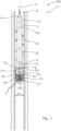
- Fig. 1 shows a downhole wireline tool 1 for performing an operation on a rotatable component part mounted as part of a well tubular metal structure in a well.
- the downhole wireline tool has an axial extension 2 along the extension of the well and a front face 3 facing down the well away from a top of the well.
- the downhole wireline tool 1 comprises a wireline connection unit 4 for connection to a wireline 5, an electric motor 6 powered by the wireline 5 for rotating a rotatable shaft 7 and a gearing system 8 driven by an electric motor 6.
- the gearing system 8 comprises a first gearing part 9 connected with the rotatable shaft 7 and configured to rotate in a first direction D1.
- the gearing system 8 further comprises an intermediate gearing part 10 rotated by the first gearing part 9 and a second gearing part 11 rotated by the intermediate gearing part 10 to rotate in a second direction D2 opposite the first direction D1.
- the first gearing part 9 is connected to a first output shaft 14 that is rotatable with the first gearing part 9 in the first direction D1
- the second gearing part 11 is connected to a second output shaft 15 that is hollow and rotatable with the second gearing part 11 in the second direction D2, the first output shaft 14 extending through the second output shaft 15.
- the downhole wireline tool 1 is able to also drill out rotating objects in a completion of a well in an easy, safe and quick manner.
- the downhole wireline tool 1 further comprises a first machining bit 16 forming the front face 3 and connected to and rotated by the first output shaft 14.
- the first machining bit 16 is rotated for machining through a stuck completion component in the well, such as a stuck plug or a ball in a ball seat.
- the second output shaft 15 is a hollow shaft rotating around the first output shaft 14.
- the second output shaft 15 is connected to a gripping element or a second machining bit 17 forming the front face 3 and being connected to and rotated by the second output shaft 15.
- the second machining bit 17 is rotated in the second direction D2 opposite the first direction D1 so that the second machining bit 17 grips in the circumference of e.g.
- the first machining bit 16 rotating in the first direction D1 is able to machine through the rotatable ball as the second machining bit 17 grips in the ball and fixates the ball in relation to the second machining bit 17 so that the first machining bit 16 is able to rotate in relation to the ball, which is required for the first machining bit 16 to be able to perform the machining operation.
- the second machining bit 17 is a tubular second machining bit having a circumference and circumferenting the first machining bit 16.
- the first machining bit 16 is also hollow.
- the first machining bit 16 is a drill bit such as a pilot bit or a similar bit able to cut its way through the rotatable part of the component by drilling.
- the operation on a rotatable component part mounted as part of the well tubular metal structure may also be performed on a plug where the plug has a rotatable part at the upper part near its circumference, and the centre is fixed in relation to the well tubular metal structure.
- the downhole wireline tool 1 needs to be able to rotate the inner part in relation to the plug and to machine very closely to the circumference of the plug in order to remove as much as possible of the plug and provide as large an inner diameter of the well tubular metal structure as possible.
- the first machining bit 16 and the second machining bit 17 need to rotate in opposite directions and as closely to the circumference of the plug as possible, and thus both bits need to contact the rotatable part of the plug and be able to machine through the rotatable part.
- the remaining machining operation is performed on the fixed part of the plug.
- the first machining bit 16 has a first outer diameter OD1
- the second machining bit 17 has a second inner diameter ID2 that is larger than the first outer diameter OD1.
- the first machining bit 16 is tubular, having a first inner diameter ID1 that is less than 10 mm smaller than the first outer diameter OD1, preferably less than 7 mm, and more preferably less than 5 mm.
- the second machining bit 17 is tubular, having a second inner diameter ID2 that is less than 10 mm smaller than the second outer diameter OD2, preferably less than 7 mm, and more preferably less than 5 mm.
- the second inner diameter ID2 is less than 5 mm larger than the first outer diameter OD1, preferably less than 2 mm, so that the first machining bit 16 can machine very closely to the second machining bit 17 in order for both bits to engage the rotatable part of the plug.
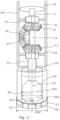
- the first machining bit 16 comprises inserts 18 extending from the front face along the axial extension 2.
- the second machining bit 17 also comprises inserts 18 extending from the front face along the axial extension 2.
- the inserts 18 are distributed along the circumference and with a distance d between the inserts 18.
- the inserts are abrasive inserts comprising grains and binder. The grains are made of tungsten carbide, diamonds or the like.
- the first machining bit 16 has the front face 3 facing away from the tool towards the component to be removed, and the first machining bit 16 comprises a central bore 19 extending from the front face 3 towards the first gearing part 9.
- the first machining bit 16 has a first rotation axis 41
- the second machining bit 17 has a second rotation axis 42, the first rotation axis 41 being coincident with the second rotation axis 42.
- the first machining bit 16 has the centre bore and is thus hollow, and a centre bit 29 is arranged inside the first machining bit 16. In this way, the centre part of the component is also grinded or even pulverised so that no large unmachined piece, also known as a coupon, is left in the well.
- the gearing system 8 comprises the intermediate gearing part 10 rotated by the first gearing part 9 to rotate the second gearing part 11 in the second direction D2.
- the intermediate gearing part 10 is fixated in relation to a tool housing 24 by means of a fastening element 23 which is connected to the electric motor 6.
- the axis of rotation of the intermediate gearing part 10 is perpendicular to the first rotation axis 41 and the second rotation axis 42, and the teeth of the intermediate gearing part 10 engage both the teeth of the first gearing part 9 and the teeth of the second gearing part 11; thus, the rotation of the first gearing part 9 is transmitted to rotation of the second gearing part 11 in a direction opposite to the first direction D1.
- the second gearing part 11 forms part of the second machining bit 17, and the first output shaft 14 is connected to the first machining bit 16.
- the first output shaft 14 extends through the second gearing part 11.
- the first gearing part 9 and the second gearing part 11 have holes in order to reduce their weight.
- the gearing parts 9, 11 are conventional toothed gears.
- the intermediate gearing part 10, the first gearing part 9 and the second gearing part 11 are bevel gears, and the intermediate gearing part 10 rotates around a bearing 23 which is connected to the tool housing 24 and forms the fastening element 23.
- the second gearing part 11 forms part of the second machining bit 17, the first output shaft 14 is connected to the first machining bit 16, and the first output shaft 14 extends through the second gearing part 11.
- the second machining bit 17 comprises a cutting element forming the front face 3.
- the second output shaft 15 is connected to the gripping element having spikes or similar gripping parts for engaging the rotatable part of the component to be machined away, i.e. grinded or milled out.
- the intermediate gearing part 10, the first gearing part 9 and the second gearing part 11 form a planetary gear having three intermediate gearing parts 10 forming the sun gears, the first gearing part 9 forming the centre gear, and the second gearing part 11 forming the ring gear.
- the three intermediate gearing parts 10 are rotating around pins on a carrier plate part which is fixed to the tool housing 24 so that the carrier plate part 23 forms the fastening element 23.
- the second gearing part 11 is connected to the second output shaft 15 and rotates in the second direction D2.
- the first gearing part 9 is driven by the rotatable shaft 7 rotating in the first direction D1, and the first gearing part 9 rotates the first output shaft 14 in the first direction D1.
- the first output shaft 14 is connected to the first machining bit 16.
- the downhole wireline tool 1 may further comprise a reduction gear 43, such as a pericyclic gear 43, as shown in Fig. 4 .
- the pericyclic gear 43 may be a pericyclic nutating gear such as a wobbling gear or a nutating bevel gear for reducing the rotational speed of the rotatable shaft 7.
- the pericyclic gear 43 comprises a reaction control member 44 driven by the rotatable shaft 7, a pericyclic motion converter 45 driven by the reaction control member 44, an output gear 46 driven by the pericyclic motion converter 45 for driving an output rotatable shaft 7' connected to the first gearing part 9.
- the pericyclic motion converter 45 is the wobbling element.
- the nutating wobble motion will cause fluctuating moments around an axis 50 which alternates between a CW direction 51 and a CCW direction 52.
- the rotational speed of the rotatable shaft 7 is thus reduced at the output rotatable shaft 7'.
- the rotatable shaft 7, the output rotatable shaft 7' and the centre part of the pericyclic gear 43 are hollow so that electric lines or hydraulic lines can pass through them.
- Teeth 48, 48a of the reaction control member 44 engage a first set of teeth 48, 48b of the pericyclic motion converter 45, and a second set of teeth 48, 48c of the pericyclic motion converter 45 engages teeth 48, 48d of the output gear 46, which is connected to the output rotatable shaft 7'.
- the reaction control member 44 has the teeth 48a with a teeth number Z1 engaging the teeth 48b with a teeth number Z2 on one side of the pericyclic motion converter 45, and on the other side of the pericyclic motion converter 45, the teeth 48c with a teeth number Z3 engage the teeth 48d with a teeth number Z4 of the output gear 46 in order to reduce the rotational speed of the rotatable 7.
- the teeth number Z1 is one tooth 48 less than the teeth number Z2, and the teeth number Z3 is one tooth less than the teeth number Z4.
- the teeth number Z1/Z2 may be 40/41, and the teeth number Z3/Z4 may be 61/60, which corresponds to a reduction ratio of 1:123.
- the teeth number Z1/Z2 may also be 20/21, and the teeth number Z3/Z4 may be 32/31, which corresponds to a reduction ratio of 1:59.
- the reduction ratio may be up to 1:1000.
- the reduction gear 43 is thus a double or two-sided nutating bevel gear or wobbling gear.
- the pericyclic gear 43 is a reduction gear for reducing rotation of the rotational shaft with a reduction ratio of at least 1:10, preferably at least 1:50, more preferably at least 1:100, even more preferably at least 1:200, and even more preferably at least 1:1000.
- the reduction gear 43 By using a pericyclic gear 43 such as a wobbling gear or a nutating bevel gear for reducing the rotational speed of the rotatable shaft 7, the reduction gear 43 has a higher efficiency than conventional planetary reduction gears.
- the wobbling gear or nutating bevel gear is also more robust, easier to mount and requires less space.
- the tools are internally pressure-compensated, and thus fluid acts against any motion, which means that by using a wobbling gear or a nutating bevel gear, the efficiency is higher as the teeth do not intentionally act as "scoop wheel".
- the reduction gear 43 is arranged between the electric motor 6 and the gearing system 8, providing the double rotational movement.
- the reduction gear 43 comprises bearings 47 arranged between the rotatable shaft 7 and the reaction control member 44, the pericyclic motion converter 45 and the output gear 46.
- the reduction gear 43 is also a wobbling gear or a nutating bevel gear, but the output gear 46 has a larger diameter than that of the reaction control member 44.
- the wobbling pericyclic motion converter 45 has a diameter on one side matching the diameter of the output gear 46 and on the other side a diameter matching the diameter of the reaction control member 44.
- the reduction gear 43 can be made with an overall smaller outer diameter than that in Fig. 4 .
- the rotatable shaft 7 and the output rotatable shaft 7' have a hollow passage for electric lines and/or hydraulic lines.
- Fig. 6 shows a reduction gear 43 which is a balanced pericyclic transmission in that the reduction gear of Fig. 4 is supplemented with a balancing part of a similar configuration in order to outbalance any vibration caused by the reduction gear 43 of Fig. 4 .
- the function of the reduction gear 43 shown in Fig. 6 is the same as the reduction gear 43 shown in Fig 4 .
- the rotatable shafts 7, 7' are hollow, and the number of teeth is the same.
- the reduction gear 43 shown in Fig. 7 also comprises a wobbling pericyclic motion converter 45 as in Figs. 4-6 , but the set of teeth 48b engaging the teeth 48a of the reaction control member 44 is positioned on the same side of the wobbling pericyclic motion converter 45 as the teeth 48c engaging the teeth 48d of the output gear 46.
- the reduction gear 43 of Fig. 7 has a larger outer diameter OD than that of the gears in Figs. 4-6 , but a shorter extension along the axial extension 2 for the same strength and number of teeth.
- the rotatable shafts 7, 7' are hollow for electric and/or hydraulic feedthrough.
- a downhole system 100 comprising the downhole wireline tool 1 and a driving unit 32, such as a downhole tractor, for propelling the downhole system forward in the well.
- the downhole wireline tool 1 further comprises an electric control unit 31, and the wireline connection unit 4 is connected to the electric control unit 31.
- the downhole wireline tool 1 also comprises an anchoring section 33 for anchoring the tool at a position in the well so that a first tool part 21 of the tool comprising the wireline connection unit 4 is prevented from moving along the axial extension 2.
- the downhole wireline tool 1 comprises a second tool part 22 rotating in relation to the first tool part 21, the second tool part 22 comprising the first machining bit 16.
- fluid or well fluid any kind of fluid that may be present in oil or gas wells downhole, such as natural gas, oil, oil mud, crude oil, water, etc.
- gas any kind of gas composition present in a well, completion or open hole
- oil any kind of oil composition, such as crude oil, an oil-containing fluid, etc.
- Gas, oil and water fluids may thus all comprise other elements or substances than gas, oil and/or water, respectively.
- casing or well tubular metal structure is meant any kind of pipe, tubing, tubular, liner, string, etc., used downhole in relation to oil or natural gas production.
- a downhole tractor can be used to push the tool all the way into position in the well.
- the downhole tractor may have projectable arms having wheels, wherein the wheels contact the inner surface of the casing for propelling the tractor and the tool forward in the casing.
- a downhole tractor is any kind of driving tool capable of pushing or pulling tools in a well downhole, such as a Well Tractor ® .
Landscapes
- Engineering & Computer Science (AREA)
- Life Sciences & Earth Sciences (AREA)
- Geology (AREA)
- Mining & Mineral Resources (AREA)
- Physics & Mathematics (AREA)
- Environmental & Geological Engineering (AREA)
- Fluid Mechanics (AREA)
- General Life Sciences & Earth Sciences (AREA)
- Geochemistry & Mineralogy (AREA)
- Mechanical Engineering (AREA)
- Finish Polishing, Edge Sharpening, And Grinding By Specific Grinding Devices (AREA)
- Processing Of Stones Or Stones Resemblance Materials (AREA)
Abstract
The present invention relates to a downhole wireline tool for performing an operation on a rotatable component part mounted as part of a well tubular metal structure in a well, the downhole wireline tool having an axial extension and a front face facing away from a top of the well, and the downhole wireline tool comprising a wireline connection unit for connection to a wireline, an electric motor powered by the wireline for rotating a rotatable shaft, and a gearing system driven by the electric motor, the gearing system comprising a first gearing part connected with the rotatable shaft and configured to rotate in a first direction, wherein the gearing system further comprises an intermediate gearing part rotated by the first gearing part and a second gearing part rotated by the intermediate gearing part to rotate in a second direction opposite the first direction. The invention also relates to a downhole system comprising the downhole wireline tool and a driving unit, such as a downhole tractor, for propelling the downhole system forward in the well.
Description
- The present invention relates to a downhole wireline tool for performing an operation on a rotatable component part mounted as part of a well tubular metal structure in a well, the downhole wireline tool having an axial extension and a front face facing away from a top of the well. The invention also relates to a downhole system comprising the downhole wireline tool and a driving unit, such as a downhole tractor, for propelling the downhole system forward in the well.
- During fracturing operations, balls with varying diameters are dropped down the well in order to be seated in a matching ball seat, and some balls are designed to release and others to dissolve after a predetermined period of time. When this operation fails, the balls need to be drilled out, which can be very troublesome as machining in a rotating object is not easy, and therefore several designs have been tried out. Also, when drilling out other objects such as a stuck plug rotating, part of the plug may hinder easy removal as a rotating object like the ball just rotates along with the rotating drilling bit seeks to drill out the ball or plug.
- It is an object of the present invention to wholly or partly overcome the above disadvantages and drawbacks of the prior art. More specifically, it is an object to provide an improved downhole wireline tool able to also drill out rotating objects in a completion of a well in an easy, safe and quick manner.
- The above objects, together with numerous other objects, advantages and features, which will become evident from the below description, are accomplished by a solution in accordance with the present invention by a downhole wireline tool for performing an operation on a rotatable component part mounted as part of a well tubular metal structure in a well, the downhole wireline tool having an axial extension and a front face facing away from a top of the well, and the downhole wireline tool comprising:
- a wireline connection unit for connection to a wireline,
- an electric motor powered by the wireline for rotating a rotatable shaft, and
- a gearing system driven by the electric motor, the gearing system comprising a first gearing part connected with the rotatable shaft and configured to rotate in a first direction,
- Also, the first gearing part may be connected to a first output shaft rotatable with the first gearing part in the first direction, and the second gearing part may be connected to a second output shaft that is hollow and rotatable with the second gearing part in the second direction, the first output shaft extending through the second output shaft.
- Moreover, the downhole wireline tool may further comprise a first machining bit forming the front face and being connected to and rotated by the first output shaft.
- Furthermore, the second output shaft may be a hollow shaft rotating around the first output shaft.
- In addition, the second output shaft may be connected to a gripping element or a second machining bit forming the front face and being connected to and rotated by the second output shaft.
- Further, the first machining bit may be hollow.
- Also, the first machining bit may have a first outer diameter, and the second machining bit may have a second inner diameter that is larger than the first outer diameter.
- Furthermore, the first machining bit may be tubular, having a first inner diameter that is less than 10 mm smaller than the first outer diameter, preferably less than 7 mm, and more preferably less than 5 mm.
- In addition, the second machining bit may be tubular, having a second inner diameter that is less than 10 mm smaller than the second outer diameter, preferably less than 7 mm, and more preferably less than 5 mm.
- Moreover, the second inner diameter may be less than 5 mm larger than the first outer diameter.
- Further, the first machining bit may comprise inserts extending from the front face along the axial extension.
- Also, the second machining bit may be a tubular second machining bit having a circumference and circumferenting the first machining bit.
- Furthermore, the second machining bit may comprise inserts extending from the front face along the axial extension.
- In addition, the second machining bit may comprise inserts distributed along the circumference.
- Moreover, the inserts may be abrasive inserts.
- Further, the inserts may comprise grains and binder.
- Also, the grains may be made of tungsten carbide, diamonds or the like.
- Furthermore, the first machining bit may have a front face facing away from the tool towards the component to be removed, the first machining bit comprising a
central bore 19 extending from the front face towards the first gearing part. - In addition, the first machining bit may have a first rotation axis, and the second machining bit may have a second rotation axis, the first rotation axis being coincident with the second rotation axis.
- Moreover, the downhole wireline tool may further comprise a reduction gear, such as a pericyclic gear, a wobbling gear or a nutating bevel gear, for reducing the rotational speed of the rotatable shaft.
- Also, the pericyclic gear may be a pericyclic nutating gear such as a wobbling gear or a nutating bevel gear.
- In addition, the reduction gear may be a pericyclic nutating gear such as a wobbling or a nutating bevel gear for reducing the rotational speed of the rotatable shaft with a reduction ratio of at least 1:10, preferably at least 1:50, more preferably at least 1:100, even more preferably at least 1:200, and even more preferably at least 1:1000.
- Further, the pericyclic gear may comprise a reaction control member driven by the rotatable shaft, a pericyclic motion converter driven by the reaction control member, and an output gear driven by the pericyclic motion converter for driving an output rotatable shaft connected to the first gearing part.
- Also, the pericyclic gear may be a double-sided nutating bevel gear.
- In addition, the reduction gear may be arranged between the motor and the gearing system.
- Moreover, the reduction gear may comprise bearings arranged between the rotatable shaft and the reaction control member, the pericyclic motion converter and the output gear.
- Further, the teeth of the reaction control member may engage a first set of teeth of the pericyclic motion converter, and a second set of teeth of the pericyclic motion converter may engage teeth of the output gear, the output gear being connected to the output shaft.
- Also, the downhole wireline tool may comprise a housing and a fixture for fixating the intermediate gearing part.
- Furthermore, the downhole wireline tool may also comprise an electric control unit, the wireline connection unit being connected to the electric control unit.
- In addition, the downhole wireline tool may further comprise a driving unit, such as a downhole tractor, for propelling the tool forward in the well.
- Moreover, the downhole wireline tool may further comprise an anchoring section for anchoring the tool at a position in the well so that a first tool part of the tool comprising the wireline connection unit is prevented from moving along the axial extension.
- Further, the tool may comprise a second tool part rotating in relation to the first tool part.
- Also, the first machining bit may be a drill bit such as a pilot bit.
- Finally, the invention relates to a downhole system comprising the downhole wireline tool and a driving unit, such as a downhole tractor, for propelling the downhole system forward in the well.
- The invention and its many advantages will be described in more detail below with reference to the accompanying schematic drawings, which for the purpose of illustration show some non-limiting embodiments and in which:
-
Fig. 1 shows a partly cross-sectional view of a downhole wireline tool, -
Fig. 2 shows a partly cross-sectional view of part of another downhole wireline tool having a gearing system comprising a first gearing part configured to rotate in a first direction and a second gearing part rotating opposite the first direction, -
Fig. 3 shows a partly cross-sectional view of part of yet another downhole wireline tool, -
Fig. 4 shows a partly cross-sectional view of a pericyclic gear of another downhole tool, -
Fig. 5 shows a cross-sectional view of another pericyclic gear of another downhole tool, -
Fig. 6 shows a cross-sectional view of yet another pericyclic gear of another downhole tool, -
Fig. 7 shows a cross-sectional view of yet another pericyclic gear of another downhole tool, and -
Fig. 8 shows another gearing system. - All the figures are highly schematic and not necessarily to scale, and they show only those parts which are necessary in order to elucidate the invention, other parts being omitted or merely suggested.
-
Fig. 1 shows adownhole wireline tool 1 for performing an operation on a rotatable component part mounted as part of a well tubular metal structure in a well. The downhole wireline tool has anaxial extension 2 along the extension of the well and afront face 3 facing down the well away from a top of the well. Thedownhole wireline tool 1 comprises awireline connection unit 4 for connection to awireline 5, anelectric motor 6 powered by thewireline 5 for rotating arotatable shaft 7 and agearing system 8 driven by anelectric motor 6. Thegearing system 8 comprises afirst gearing part 9 connected with therotatable shaft 7 and configured to rotate in a first direction D1. Thegearing system 8 further comprises anintermediate gearing part 10 rotated by thefirst gearing part 9 and asecond gearing part 11 rotated by theintermediate gearing part 10 to rotate in a second direction D2 opposite the first direction D1. Thefirst gearing part 9 is connected to afirst output shaft 14 that is rotatable with thefirst gearing part 9 in the first direction D1, and thesecond gearing part 11 is connected to asecond output shaft 15 that is hollow and rotatable with thesecond gearing part 11 in the second direction D2, thefirst output shaft 14 extending through thesecond output shaft 15. - By having the
gearing system 8 providing a first rotation in the first direction D1 and a second rotation in the second direction D2, thedownhole wireline tool 1 is able to also drill out rotating objects in a completion of a well in an easy, safe and quick manner. - The
downhole wireline tool 1 further comprises afirst machining bit 16 forming thefront face 3 and connected to and rotated by thefirst output shaft 14. Thefirst machining bit 16 is rotated for machining through a stuck completion component in the well, such as a stuck plug or a ball in a ball seat. Thesecond output shaft 15 is a hollow shaft rotating around thefirst output shaft 14. Thesecond output shaft 15 is connected to a gripping element or asecond machining bit 17 forming thefront face 3 and being connected to and rotated by thesecond output shaft 15. Thesecond machining bit 17 is rotated in the second direction D2 opposite the first direction D1 so that thesecond machining bit 17 grips in the circumference of e.g. the rotatable ball; by rotating thesecond machining bit 17 in the second direction D2, thefirst machining bit 16 rotating in the first direction D1 is able to machine through the rotatable ball as thesecond machining bit 17 grips in the ball and fixates the ball in relation to thesecond machining bit 17 so that thefirst machining bit 16 is able to rotate in relation to the ball, which is required for thefirst machining bit 16 to be able to perform the machining operation. InFig. 1 , thesecond machining bit 17 is a tubular second machining bit having a circumference and circumferenting thefirst machining bit 16. Thefirst machining bit 16 is also hollow. In another solution, thefirst machining bit 16 is a drill bit such as a pilot bit or a similar bit able to cut its way through the rotatable part of the component by drilling. - The operation on a rotatable component part mounted as part of the well tubular metal structure may also be performed on a plug where the plug has a rotatable part at the upper part near its circumference, and the centre is fixed in relation to the well tubular metal structure. When removing such stuck plug by machining, the
downhole wireline tool 1 needs to be able to rotate the inner part in relation to the plug and to machine very closely to the circumference of the plug in order to remove as much as possible of the plug and provide as large an inner diameter of the well tubular metal structure as possible. Thefirst machining bit 16 and thesecond machining bit 17 need to rotate in opposite directions and as closely to the circumference of the plug as possible, and thus both bits need to contact the rotatable part of the plug and be able to machine through the rotatable part. When machining through the rotatable part, the remaining machining operation is performed on the fixed part of the plug. Thus, thefirst machining bit 16 has a first outer diameter OD1, and thesecond machining bit 17 has a second inner diameter ID2 that is larger than the first outer diameter OD1. Thefirst machining bit 16 is tubular, having a first inner diameter ID1 that is less than 10 mm smaller than the first outer diameter OD1, preferably less than 7 mm, and more preferably less than 5 mm. Thesecond machining bit 17 is tubular, having a second inner diameter ID2 that is less than 10 mm smaller than the second outer diameter OD2, preferably less than 7 mm, and more preferably less than 5 mm. The second inner diameter ID2 is less than 5 mm larger than the first outer diameter OD1, preferably less than 2 mm, so that thefirst machining bit 16 can machine very closely to thesecond machining bit 17 in order for both bits to engage the rotatable part of the plug. - In
Fig. 2 , thefirst machining bit 16 comprisesinserts 18 extending from the front face along theaxial extension 2. Thesecond machining bit 17 also comprisesinserts 18 extending from the front face along theaxial extension 2. Theinserts 18 are distributed along the circumference and with a distance d between theinserts 18. The inserts are abrasive inserts comprising grains and binder. The grains are made of tungsten carbide, diamonds or the like. As shown inFig. 3 , thefirst machining bit 16 has thefront face 3 facing away from the tool towards the component to be removed, and thefirst machining bit 16 comprises acentral bore 19 extending from thefront face 3 towards thefirst gearing part 9. - The
first machining bit 16 has afirst rotation axis 41, and thesecond machining bit 17 has asecond rotation axis 42, thefirst rotation axis 41 being coincident with thesecond rotation axis 42. Thefirst machining bit 16 has the centre bore and is thus hollow, and acentre bit 29 is arranged inside thefirst machining bit 16. In this way, the centre part of the component is also grinded or even pulverised so that no large unmachined piece, also known as a coupon, is left in the well. - In order to rotate the
first output shaft 14 in the first direction D1 and thesecond output shaft 15 in the opposite second direction D2, thegearing system 8 comprises theintermediate gearing part 10 rotated by thefirst gearing part 9 to rotate thesecond gearing part 11 in the second direction D2. InFig. 2 , theintermediate gearing part 10 is fixated in relation to atool housing 24 by means of afastening element 23 which is connected to theelectric motor 6. The axis of rotation of theintermediate gearing part 10 is perpendicular to thefirst rotation axis 41 and thesecond rotation axis 42, and the teeth of theintermediate gearing part 10 engage both the teeth of thefirst gearing part 9 and the teeth of thesecond gearing part 11; thus, the rotation of thefirst gearing part 9 is transmitted to rotation of thesecond gearing part 11 in a direction opposite to the first direction D1. Thesecond gearing part 11 forms part of thesecond machining bit 17, and thefirst output shaft 14 is connected to thefirst machining bit 16. Thefirst output shaft 14 extends through thesecond gearing part 11. Thefirst gearing part 9 and thesecond gearing part 11 have holes in order to reduce their weight. Thegearing parts - In
Fig. 3 , theintermediate gearing part 10, thefirst gearing part 9 and thesecond gearing part 11 are bevel gears, and theintermediate gearing part 10 rotates around abearing 23 which is connected to thetool housing 24 and forms thefastening element 23. Thesecond gearing part 11 forms part of thesecond machining bit 17, thefirst output shaft 14 is connected to thefirst machining bit 16, and thefirst output shaft 14 extends through thesecond gearing part 11. Thesecond machining bit 17 comprises a cutting element forming thefront face 3. In another solution, thesecond output shaft 15 is connected to the gripping element having spikes or similar gripping parts for engaging the rotatable part of the component to be machined away, i.e. grinded or milled out. - In
Fig. 8 , theintermediate gearing part 10, thefirst gearing part 9 and thesecond gearing part 11 form a planetary gear having threeintermediate gearing parts 10 forming the sun gears, thefirst gearing part 9 forming the centre gear, and thesecond gearing part 11 forming the ring gear. The threeintermediate gearing parts 10 are rotating around pins on a carrier plate part which is fixed to thetool housing 24 so that thecarrier plate part 23 forms thefastening element 23. Thesecond gearing part 11 is connected to thesecond output shaft 15 and rotates in the second direction D2. Thefirst gearing part 9 is driven by therotatable shaft 7 rotating in the first direction D1, and thefirst gearing part 9 rotates thefirst output shaft 14 in the first direction D1. Thefirst output shaft 14 is connected to thefirst machining bit 16. - In order to reduce the rotational speed of the
first output shaft 14, thedownhole wireline tool 1 may further comprise areduction gear 43, such as apericyclic gear 43, as shown inFig. 4 . Thepericyclic gear 43 may be a pericyclic nutating gear such as a wobbling gear or a nutating bevel gear for reducing the rotational speed of therotatable shaft 7. Thepericyclic gear 43 comprises areaction control member 44 driven by therotatable shaft 7, apericyclic motion converter 45 driven by thereaction control member 44, anoutput gear 46 driven by thepericyclic motion converter 45 for driving an output rotatable shaft 7' connected to thefirst gearing part 9. Thepericyclic motion converter 45 is the wobbling element. The nutating wobble motion will cause fluctuating moments around an axis 50 which alternates between a CW direction 51 and a CCW direction 52. The rotational speed of therotatable shaft 7 is thus reduced at the output rotatable shaft 7'. Therotatable shaft 7, the output rotatable shaft 7' and the centre part of thepericyclic gear 43 are hollow so that electric lines or hydraulic lines can pass through them.Teeth reaction control member 44 engage a first set ofteeth pericyclic motion converter 45, and a second set ofteeth pericyclic motion converter 45 engagesteeth output gear 46, which is connected to the output rotatable shaft 7'. Thereaction control member 44 has theteeth 48a with a teeth number Z1 engaging theteeth 48b with a teeth number Z2 on one side of thepericyclic motion converter 45, and on the other side of thepericyclic motion converter 45, theteeth 48c with a teeth number Z3 engage theteeth 48d with a teeth number Z4 of theoutput gear 46 in order to reduce the rotational speed of therotatable 7. The teeth number Z1 is onetooth 48 less than the teeth number Z2, and the teeth number Z3 is one tooth less than the teeth number Z4. The teeth number Z1/Z2 may be 40/41, and the teeth number Z3/Z4 may be 61/60, which corresponds to a reduction ratio of 1:123. The teeth number Z1/Z2 may also be 20/21, and the teeth number Z3/Z4 may be 32/31, which corresponds to a reduction ratio of 1:59. Thus, the reduction ratio may be up to 1:1000. Thereduction gear 43 is thus a double or two-sided nutating bevel gear or wobbling gear. InFig. 4 , thepericyclic gear 43 is a reduction gear for reducing rotation of the rotational shaft with a reduction ratio of at least 1:10, preferably at least 1:50, more preferably at least 1:100, even more preferably at least 1:200, and even more preferably at least 1:1000. - By using a
pericyclic gear 43 such as a wobbling gear or a nutating bevel gear for reducing the rotational speed of therotatable shaft 7, thereduction gear 43 has a higher efficiency than conventional planetary reduction gears. The wobbling gear or nutating bevel gear is also more robust, easier to mount and requires less space. In downhole wireline tools, the tools are internally pressure-compensated, and thus fluid acts against any motion, which means that by using a wobbling gear or a nutating bevel gear, the efficiency is higher as the teeth do not intentionally act as "scoop wheel". - The
reduction gear 43 is arranged between theelectric motor 6 and thegearing system 8, providing the double rotational movement. Thereduction gear 43 comprisesbearings 47 arranged between therotatable shaft 7 and thereaction control member 44, thepericyclic motion converter 45 and theoutput gear 46. - In
Fig. 5 , thereduction gear 43 is also a wobbling gear or a nutating bevel gear, but theoutput gear 46 has a larger diameter than that of thereaction control member 44. The wobblingpericyclic motion converter 45 has a diameter on one side matching the diameter of theoutput gear 46 and on the other side a diameter matching the diameter of thereaction control member 44. By having varying diameters, thereduction gear 43 can be made with an overall smaller outer diameter than that inFig. 4 . As can be seen, therotatable shaft 7 and the output rotatable shaft 7' have a hollow passage for electric lines and/or hydraulic lines. -
Fig. 6 shows areduction gear 43 which is a balanced pericyclic transmission in that the reduction gear ofFig. 4 is supplemented with a balancing part of a similar configuration in order to outbalance any vibration caused by thereduction gear 43 ofFig. 4 . The function of thereduction gear 43 shown inFig. 6 is the same as thereduction gear 43 shown inFig 4 . Therotatable shafts 7, 7' are hollow, and the number of teeth is the same. - The
reduction gear 43 shown inFig. 7 also comprises a wobblingpericyclic motion converter 45 as inFigs. 4-6 , but the set ofteeth 48b engaging theteeth 48a of thereaction control member 44 is positioned on the same side of the wobblingpericyclic motion converter 45 as theteeth 48c engaging theteeth 48d of theoutput gear 46. Thereduction gear 43 ofFig. 7 has a larger outer diameter OD than that of the gears inFigs. 4-6 , but a shorter extension along theaxial extension 2 for the same strength and number of teeth. Therotatable shafts 7, 7' are hollow for electric and/or hydraulic feedthrough. - In
Fig. 1 , adownhole system 100 is shown comprising thedownhole wireline tool 1 and a drivingunit 32, such as a downhole tractor, for propelling the downhole system forward in the well. Thedownhole wireline tool 1 further comprises anelectric control unit 31, and thewireline connection unit 4 is connected to theelectric control unit 31. Thedownhole wireline tool 1 also comprises ananchoring section 33 for anchoring the tool at a position in the well so that afirst tool part 21 of the tool comprising thewireline connection unit 4 is prevented from moving along theaxial extension 2. Thedownhole wireline tool 1 comprises asecond tool part 22 rotating in relation to thefirst tool part 21, thesecond tool part 22 comprising thefirst machining bit 16. - By fluid or well fluid is meant any kind of fluid that may be present in oil or gas wells downhole, such as natural gas, oil, oil mud, crude oil, water, etc. By gas is meant any kind of gas composition present in a well, completion or open hole, and by oil is meant any kind of oil composition, such as crude oil, an oil-containing fluid, etc. Gas, oil and water fluids may thus all comprise other elements or substances than gas, oil and/or water, respectively.
- By casing or well tubular metal structure is meant any kind of pipe, tubing, tubular, liner, string, etc., used downhole in relation to oil or natural gas production.
- In the event that the tool is not submergible all the way into the casing, a downhole tractor can be used to push the tool all the way into position in the well. The downhole tractor may have projectable arms having wheels, wherein the wheels contact the inner surface of the casing for propelling the tractor and the tool forward in the casing. A downhole tractor is any kind of driving tool capable of pushing or pulling tools in a well downhole, such as a Well Tractor®.
- Although the invention has been described above in connection with preferred embodiments of the invention, it will be evident to a person skilled in the art that several modifications are conceivable without departing from the invention as defined by the following claims.
Claims (15)
- A downhole wireline tool (1) for performing an operation on a rotatable component part mounted as part of a well tubular metal structure in a well, the downhole wireline tool having an axial extension (2) and a front face (3) facing away from a top of the well, and the downhole wireline tool comprising:- a wireline connection unit (4) for connection to a wireline (5),- an electric motor (6) powered by the wireline for rotating a rotatable shaft (7), and- a gearing system (8) driven by the electric motor, the gearing system comprising a first gearing part (9) connected with the rotatable shaft and configured to rotate in a first direction (D1),wherein the gearing system further comprises an intermediate gearing part (10) rotated by the first gearing part and a second gearing part (11) rotated by the intermediate gearing part to rotate in a second direction (D2) opposite the first direction.
- A downhole wireline tool according to claim 1, wherein the first gearing part is connected to a first output shaft (14) that is rotatable with the first gearing part in the first direction, and the second gearing part is connected to a second output shaft (15) that is hollow and rotatable with the second gearing part in the second direction, the first output shaft extending through the second output shaft.
- A downhole wireline tool according to claim 2, further comprising a first machining bit (16) forming the front face and connected to and rotated by the first output shaft.
- A downhole wireline tool according to claim 2 or 3, wherein the second output shaft is a hollow shaft rotating around the first output shaft.
- A downhole wireline tool according to claim 2 or 3, wherein the second output shaft is connected to a gripping element or a second machining bit (17) forming the front face and connected to and rotated by the second output shaft.
- A downhole wireline tool according to claim 4, wherein the first machining bit has a first outer diameter (OD1), and the second machining bit has a second inner diameter (ID2) that is larger than the first outer diameter.
- A downhole wireline tool according to any of the preceding claims 3-6, wherein the first machining bit comprises inserts (18) extending from the front face along the axial extension.
- A downhole wireline tool according to claim 5 or 6, wherein the second machining bit is a tubular second machining bit having a circumference and circumferenting the first machining bit.
- A downhole wireline tool according to any of the preceding claims 3-8, wherein the second machining bit comprises inserts extending from the front face along the axial extension.
- A downhole wireline tool according to claim 8 or 9, wherein the second machining bit comprises inserts distributed along the circumference.
- A downhole wireline tool according to any of claims 7-10, wherein the inserts are abrasive inserts.
- A downhole wireline tool according to any of the preceding claims 3-11, wherein the first machining bit has a first rotation axis (41), and the second machining bit has a second rotation axis (42), the first rotation axis being coincident with the second rotation axis.
- A downhole wireline tool according to any of the preceding claims, further comprising a reduction gear (43), such as a pericyclic gear, a wobbling gear or a nutating bevel gear, for reducing the rotation of the rotatable shaft.
- A downhole wireline tool according to any of the preceding claims, wherein the first machining bit (16) is a drill bit such as a pilot bit.
- Downhole system (100) comprising the downhole wireline tool according to any of claims 1-14 and a driving unit, such as a downhole tractor, for propelling the downhole system forward in the well.
Priority Applications (6)
| Application Number | Priority Date | Filing Date | Title |
|---|---|---|---|
| EP23182865.8A EP4484697A1 (en) | 2023-06-30 | 2023-06-30 | Downhole wireline tool |
| EP24738250.0A EP4735725A1 (en) | 2023-06-30 | 2024-06-28 | Downhole wireline tool |
| CN202480040171.9A CN121311658A (en) | 2023-06-30 | 2024-06-28 | Downhole cable tools |
| US18/758,363 US12428921B2 (en) | 2023-06-30 | 2024-06-28 | Downhole wireline tool |
| AU2024307675A AU2024307675A1 (en) | 2023-06-30 | 2024-06-28 | Downhole wireline tool |
| PCT/EP2024/068313 WO2025003440A1 (en) | 2023-06-30 | 2024-06-28 | Downhole wireline tool |
Applications Claiming Priority (1)
| Application Number | Priority Date | Filing Date | Title |
|---|---|---|---|
| EP23182865.8A EP4484697A1 (en) | 2023-06-30 | 2023-06-30 | Downhole wireline tool |
Publications (1)
| Publication Number | Publication Date |
|---|---|
| EP4484697A1 true EP4484697A1 (en) | 2025-01-01 |
Family
ID=87060559
Family Applications (2)
| Application Number | Title | Priority Date | Filing Date |
|---|---|---|---|
| EP23182865.8A Withdrawn EP4484697A1 (en) | 2023-06-30 | 2023-06-30 | Downhole wireline tool |
| EP24738250.0A Pending EP4735725A1 (en) | 2023-06-30 | 2024-06-28 | Downhole wireline tool |
Family Applications After (1)
| Application Number | Title | Priority Date | Filing Date |
|---|---|---|---|
| EP24738250.0A Pending EP4735725A1 (en) | 2023-06-30 | 2024-06-28 | Downhole wireline tool |
Country Status (5)
| Country | Link |
|---|---|
| US (1) | US12428921B2 (en) |
| EP (2) | EP4484697A1 (en) |
| CN (1) | CN121311658A (en) |
| AU (1) | AU2024307675A1 (en) |
| WO (1) | WO2025003440A1 (en) |
Families Citing this family (1)
| Publication number | Priority date | Publication date | Assignee | Title |
|---|---|---|---|---|
| US12486729B2 (en) * | 2023-11-21 | 2025-12-02 | Saudi Arabian Oil Company | Expandable liner removal well tool |
Citations (7)
| Publication number | Priority date | Publication date | Assignee | Title |
|---|---|---|---|---|
| GB2523160A (en) * | 2014-02-14 | 2015-08-19 | Southard Drilling Technologies L P | Device and method usable in well drilling and other well operations |
| US20160215564A1 (en) * | 2013-09-10 | 2016-07-28 | Welltec A/S | Drilling tool |
| US20160222734A1 (en) * | 2013-11-25 | 2016-08-04 | Halliburton Energy Services, Inc. | Rotary steerable drilling system |
| US20160356089A1 (en) * | 2014-12-29 | 2016-12-08 | Halliburton Energy Services, Inc. | Mitigating stick-slip effects in rotary steerable tools |
| US10316602B2 (en) * | 2013-06-14 | 2019-06-11 | Welltec A/S | Downhole machining system and method |
| US20210285289A1 (en) * | 2019-10-22 | 2021-09-16 | China University Of Geosciences (Beijing) | All-metal downhole power drilling tool based on multi-stage dual plunger eccentric gear mechanism |
| US11649678B1 (en) * | 2022-07-01 | 2023-05-16 | GQ Technical LLC | Piston motor system |
Family Cites Families (7)
| Publication number | Priority date | Publication date | Assignee | Title |
|---|---|---|---|---|
| US4192380A (en) * | 1978-10-02 | 1980-03-11 | Dresser Industries, Inc. | Method and apparatus for logging inclined earth boreholes |
| US7610970B2 (en) * | 2006-12-07 | 2009-11-03 | Schlumberger Technology Corporation | Apparatus for eliminating net drill bit torque and controlling drill bit walk |
| US7562700B2 (en) * | 2006-12-08 | 2009-07-21 | Baker Hughes Incorporated | Wireline supported tubular mill |
| AU2012394996B2 (en) * | 2012-11-26 | 2016-08-11 | Halliburton Energy Services, Inc. | Well runner |
| US9759040B2 (en) * | 2013-12-20 | 2017-09-12 | Weatherford Technology Holdings, Llc | Autonomous selective shifting tool |
| EP3070257B1 (en) * | 2015-03-20 | 2018-08-08 | Welltec A/S | Downhole tool string |
| US11414965B2 (en) * | 2018-02-27 | 2022-08-16 | Schlumberger Technology Corporation | Rotating loading tube and angled shaped charges for oriented perforating |
-
2023
- 2023-06-30 EP EP23182865.8A patent/EP4484697A1/en not_active Withdrawn
-
2024
- 2024-06-28 US US18/758,363 patent/US12428921B2/en active Active
- 2024-06-28 AU AU2024307675A patent/AU2024307675A1/en active Pending
- 2024-06-28 EP EP24738250.0A patent/EP4735725A1/en active Pending
- 2024-06-28 CN CN202480040171.9A patent/CN121311658A/en active Pending
- 2024-06-28 WO PCT/EP2024/068313 patent/WO2025003440A1/en not_active Ceased
Patent Citations (7)
| Publication number | Priority date | Publication date | Assignee | Title |
|---|---|---|---|---|
| US10316602B2 (en) * | 2013-06-14 | 2019-06-11 | Welltec A/S | Downhole machining system and method |
| US20160215564A1 (en) * | 2013-09-10 | 2016-07-28 | Welltec A/S | Drilling tool |
| US20160222734A1 (en) * | 2013-11-25 | 2016-08-04 | Halliburton Energy Services, Inc. | Rotary steerable drilling system |
| GB2523160A (en) * | 2014-02-14 | 2015-08-19 | Southard Drilling Technologies L P | Device and method usable in well drilling and other well operations |
| US20160356089A1 (en) * | 2014-12-29 | 2016-12-08 | Halliburton Energy Services, Inc. | Mitigating stick-slip effects in rotary steerable tools |
| US20210285289A1 (en) * | 2019-10-22 | 2021-09-16 | China University Of Geosciences (Beijing) | All-metal downhole power drilling tool based on multi-stage dual plunger eccentric gear mechanism |
| US11649678B1 (en) * | 2022-07-01 | 2023-05-16 | GQ Technical LLC | Piston motor system |
Also Published As
| Publication number | Publication date |
|---|---|
| WO2025003440A1 (en) | 2025-01-02 |
| US20250003305A1 (en) | 2025-01-02 |
| AU2024307675A1 (en) | 2026-02-05 |
| EP4735725A1 (en) | 2026-05-06 |
| US12428921B2 (en) | 2025-09-30 |
| CN121311658A (en) | 2026-01-09 |
Similar Documents
| Publication | Publication Date | Title |
|---|---|---|
| EP1988252B1 (en) | Locking clutch for downhole motor | |
| AU2008361682B2 (en) | Locking clutch for downhole motor | |
| US6378626B1 (en) | Balanced torque drilling system | |
| EP3757345B1 (en) | Downhole wireline machining tool string | |
| CN104919131B (en) | Down-hole rotary locking mechanism | |
| US12428921B2 (en) | Downhole wireline tool | |
| US7703551B2 (en) | Fluid driven drilling motor and system | |
| CN104379864B (en) | Completion system with reaming tool | |
| CN113914780B (en) | High-speed balance pdc drill bit for petroleum drilling | |
| WO2023104899A1 (en) | Downhole wireline tool | |
| EP4484696A1 (en) | Downhole wireline tool | |
| EP3179028A1 (en) | Downhole wireline machining tool string | |
| AU2013228003B2 (en) | Locking clutch for downhole motor | |
| SU1025892A1 (en) | Core drill | |
| WO2024175165A2 (en) | An advanced autonomous drilling tool | |
| EA049505B1 (en) | DOWNHOLE WIRE TOOL COLUMN | |
| RU2272885C1 (en) | Advance bore reaming device | |
| RIDWAN | Rotor of a drilling rig for drilling oil and gas wells to a depth of 4000 m with an improvement in the device for gripping the Kelly | |
| CA2549739A1 (en) | Fluid driven drilling motor and system |
Legal Events
| Date | Code | Title | Description |
|---|---|---|---|
| PUAI | Public reference made under article 153(3) epc to a published international application that has entered the european phase |
Free format text: ORIGINAL CODE: 0009012 |
|
| STAA | Information on the status of an ep patent application or granted ep patent |
Free format text: STATUS: THE APPLICATION HAS BEEN PUBLISHED |
|
| AK | Designated contracting states |
Kind code of ref document: A1 Designated state(s): AL AT BE BG CH CY CZ DE DK EE ES FI FR GB GR HR HU IE IS IT LI LT LU LV MC ME MK MT NL NO PL PT RO RS SE SI SK SM TR |
|
| STAA | Information on the status of an ep patent application or granted ep patent |
Free format text: STATUS: THE APPLICATION IS DEEMED TO BE WITHDRAWN |
|
| 18D | Application deemed to be withdrawn |
Effective date: 20250702 |