EP4484636A1 - Gas clothes dryer - Google Patents
Gas clothes dryer Download PDFInfo
- Publication number
- EP4484636A1 EP4484636A1 EP23758933.8A EP23758933A EP4484636A1 EP 4484636 A1 EP4484636 A1 EP 4484636A1 EP 23758933 A EP23758933 A EP 23758933A EP 4484636 A1 EP4484636 A1 EP 4484636A1
- Authority
- EP
- European Patent Office
- Prior art keywords
- plate
- connecting plate
- mounting
- gas
- fired
- Prior art date
- Legal status (The legal status is an assumption and is not a legal conclusion. Google has not performed a legal analysis and makes no representation as to the accuracy of the status listed.)
- Granted
Links
Images



Classifications
-
- D—TEXTILES; PAPER
- D06—TREATMENT OF TEXTILES OR THE LIKE; LAUNDERING; FLEXIBLE MATERIALS NOT OTHERWISE PROVIDED FOR
- D06F—LAUNDERING, DRYING, IRONING, PRESSING OR FOLDING TEXTILE ARTICLES
- D06F58/00—Domestic laundry dryers
- D06F58/20—General details of domestic laundry dryers
- D06F58/26—Heating arrangements, e.g. gas heating equipment
- D06F58/263—Gas heating equipment
-
- D—TEXTILES; PAPER
- D06—TREATMENT OF TEXTILES OR THE LIKE; LAUNDERING; FLEXIBLE MATERIALS NOT OTHERWISE PROVIDED FOR
- D06F—LAUNDERING, DRYING, IRONING, PRESSING OR FOLDING TEXTILE ARTICLES
- D06F58/00—Domestic laundry dryers
- D06F58/02—Domestic laundry dryers having dryer drums rotating about a horizontal axis
-
- D—TEXTILES; PAPER
- D06—TREATMENT OF TEXTILES OR THE LIKE; LAUNDERING; FLEXIBLE MATERIALS NOT OTHERWISE PROVIDED FOR
- D06F—LAUNDERING, DRYING, IRONING, PRESSING OR FOLDING TEXTILE ARTICLES
- D06F58/00—Domestic laundry dryers
- D06F58/20—General details of domestic laundry dryers
Definitions
- Embodiments of the present application belong to the field of clothes dryer technology and, in particular, to a gas-fired clothes dryer.
- a gas-fired clothes dryer uses heat generated by the combustion of fuel gas to heat the air, and the heated dry hot air enters a clothes drying drum and contacts the wet clothes in the clothes drying drum, thereby drying the clothes.
- a gas-fired clothes dryer includes a casing, a clothes drying drum, a blower fan and a gas-fired heating device.
- An accommodating space is provided in the casing, and the clothes drying drum, the blower fan and the gas-fired heating device are all disposed in the accommodating space.
- the gas-fired heating device includes a burner, a combustion cylinder and an igniter, a spray nozzle of the burner and the igniter are both accommodated in the combustion cylinder.
- the fuel gas sprayed from the spray nozzle is ignited by the igniter, and heat generated by the combustion of the fuel gas heats the air in the combustion cylinder. Under the action of the blower fan, the heated air enters the clothes drying drum to dry the clothes in the clothes drying drum.
- the fuel gas of the gas-fired clothes dryer may be natural gas or liquefied gas.
- the burners adapted to natural gas and liquefied gas are different in structure.
- the burner mounted in the casing is adapted to natural gas, and if the user wants to use liquefied gas, the burner needs to be replaced. For replacing the burner, it is necessary to open the casing and move the clothes drying drum out of the accommodating space before replacing the burner, and the process is complicated.
- the main purpose of embodiments of the present application is to provide a gas-fired clothes dryer, so as to solve the problem that the process of replacing a burner of the gas-fired clothes dryer in the related art is complicated.
- a gas-fired clothes dryer including: a housing, a gas-fired heating device and a mounting frame, where the housing has an operating side surface, and the operating side surface is disposed toward a user, the operating side surface is provided with a maintenance port, and the maintenance port is arranged to allow the gas-fired heating device and the mounting frame to pass through; and a mounting base is disposed in the housing, the mounting base faces the maintenance port, the mounting frame is detachably connected to the mounting base, and the gas-fired heating device is connected to the mounting frame.
- a supporting plate is provided on a top of the mounting base, and the mounting base also has a connecting sidewall, the connecting sidewall is located below the supporting plate, the connecting sidewall is adjacent to the supporting plate, and the connecting sidewall is disposed toward the maintenance port; and the mounting frame includes a first connecting plate and a second connecting plate, the first connecting plate is parallel to the supporting plate, the second connecting plate is disposed at a bottom of the first connecting plate, the first connecting plate is attached to the supporting plate, the second connecting plate is attached to the connecting sidewall, and a fastening bolt is connected with the connecting sidewall after penetrating the second connecting plate.
- a first clamping plate is disposed at the bottom of the first connecting plate, the first clamping plate is perpendicular to the first connecting plate, a notch is provided at an end of the first clamping plate away from the second connecting plate, and the notch extends to the first connecting plate; and the supporting plate is provided with a first mounting hole, the first mounting hole is arranged to allow the first clamping plate to pass through, and the supporting plate is clamped in the notch.
- the first mounting hole includes a first hole section, a second hole section and a third hole section, the first hole section, the second hole section and the third hole section are connected with each other, and distances between the first hole section and the second connecting plate, between the second hole section and the second connecting plate, and between the third hole section and the second connecting plate increase in sequence; and in a direction perpendicular to the first clamping plate, a width of the third hole section is equal to a thickness of the first clamping plate, a width of the first hole section is greater than the width of the third hole section, and a width of the second hole section decreases in a direction from the first hole section to the third hole section.
- a width of the notch in a direction perpendicular to the first connecting plate is equal to a thickness of the supporting plate.
- a second clamping plate is disposed at the bottom of the first connecting plate, the second clamping plate has a fixed end and a movable end, the fixed end is connected with the first connecting plate, and the movable end extends away from the second connecting plate, and there is an accommodating gap between the second clamping plate and the first connecting plate; and the supporting plate is provided with a second mounting hole, the second mounting hole is arranged to allow the second clamping plate to pass through, and the supporting plate is clamped in the accommodating gap.
- the first connecting plate is concave downward to form a mounting groove, and a rabbet of the mounting groove forms the second mounting hole, and the second clamping plate is capable of being accommodated in the mounting groove, and a groove wall of the mounting groove away from the second connecting plate is provided with a third mounting hole, and the third mounting hole is arranged to allow the second clamping plate to pass through.
- a maintenance cover plate is disposed on the operating side surface, and the maintenance cover plate is detachably connected with the housing, and is arranged to close the maintenance port.
- the gas-fired heating device includes a burner, and the burner is detachably connected to the mounting frame.
- the burner has a first mounting plate and a second mounting plate, and a plane where the first mounting plate is located and a plane where the second mounting plate is located are coplanar; and the mounting frame further includes a third connecting plate and a fourth connecting plate, the third connecting plate and the fourth connecting plate are parallel and spaced apart from one another on a top of the first connecting plate, and are perpendicular to the first connecting plate, and a top end of the third connecting plate is bent toward the fourth connecting plate to form a first bent plate, and the first mounting plate is detachably connected with the first bent plate; and a top end of the fourth connecting plate is bent toward the third connecting plate to form a second bent plate, and the second mounting plate is detachably connected with the second bent plate.
- the mounting base is disposed in the housing, the gas-fired heating device is connected to the mounting frame, and the mounting frame is detachably connected to the mounting base; and the housing is provided with the maintenance port, and the maintenance port directly faces the mounting base and is arranged to allow the gas-fired heating device and the mounting frame to pass through.
- orientations or positional relationships indicated by the terms “inside”, “outside”, etc. are based on the orientations or positional relationships shown in the drawings, which is only for the convenience of description, and does not indicate or imply that the device or member must be of a specific orientation, be constructed and operate in a specific orientation, and therefore should not be understood as limiting the embodiments of the present application.
- connection and “connecting” should be understood in a broad sense.
- connection may be a fixed connection, a detachable connection, or an integral connection
- connection may be a mechanical connection or an electrical connection
- connection may be a direct connection or an indirect connection through an intermediate medium
- connection may be an internal communication of two members.
- a gas-fired clothes dryer in the related art includes a casing, a clothes drying drum, a blower fan and a gas-fired heating device, an accommodating space is provided in the casing, and the clothes drying drum, the blower fan and the gas-fired heating device are all disposed in the accommodating space.
- the gas-fired heating device includes a gas valve, an inlet pipe, a burner, a combustion cylinder and an igniter, the gas valve is provided with an inlet and an outlet, the inlet is connected with the inlet pipe, and the outlet is connected with the burner.
- the burner is provided with a combustion-supporting air inlet and a spray nozzle, the combustion-supporting air inlet is arranged to enable the combustion-supporting air to enter the burner, and the combustion-supporting air and the fuel gas are mixed in the burner and then sprayed from the spray nozzle.
- Both the spray nozzle and the igniter are accommodated in the combustion cylinder, and the fuel gas sprayed from the spray nozzle is ignited by the igniter, heat generated by the combustion of the fuel gas heats the air in the combustion cylinder, and under the action of the blower fan, the heated air enters the clothes drying drum to dry the clothes in the clothes drying drum.
- the fuel gas used in the gas-fired clothes dryer may be natural gas or liquefied gas, and the amount of combustion-supporting air required when natural gas and liquefied gas are combusted is quite different.
- the amount of combustion-supporting air required by liquefied gas is about three times the amount of combustion-supporting air required by natural gas, so the burners adapted to natural gas and liquefied gas are different in structure, and the combustion-supporting air inlet on the burner adapted to liquefied gas is larger than that on the burner adapted to natural gas.
- the burner mounted in the casing is adapted to natural gas, and if the user wants to use liquefied gas, the burner needs to be replaced. For replacing the burner, it is necessary to open the casing and move the clothes drying drum out of the accommodating space before replacing the burner, and the process is cumbersome.
- This embodiment provides a gas-fired clothes dryer, where a mounting base is disposed in a housing, a gas-fired heating device is connected to a mounting frame, the mounting frame is detachably connected to the mounting base, and a maintenance port is provided on the housing, and the maintenance port directly faces the mounting base.
- a gas-fired heating device is connected to a mounting frame
- the mounting frame is detachably connected to the mounting base
- a maintenance port is provided on the housing, and the maintenance port directly faces the mounting base.
- a gas-fired clothes dryer provided in embodiments of the present application includes a housing 100, a gas-fired heating device 300 and a mounting frame 400.
- An accommodating space is provided in the housing 100, and a mounting base 200 is disposed in the accommodating space.
- the housing 100 has an operating side surface 101.
- the operating side surface 101 is disposed toward the user.
- a maintenance port 102 (as shown in FIG. 1 ) is provided on the operating side surface 101, and the maintenance port 102 is connected with the accommodation space and directly faces the mounting base 200.
- the gas-fired heating device 300 is connected to the mounting frame 400.
- the gas-fired heating device 300 includes a burner 301, and the burner 301 is detachably connected to the mounting frame 400.
- the mounting frame 400 is detachably connected to the mounting base 200.
- the maintenance port 102 also directly faces the gas-fired heating device 300 and the mounting frame 400, and the gas-fired heating device 300 and the mounting frame 400 can pass through the maintenance port 102.
- the mounting frame 400 is detached from the mounting base 200 through the maintenance port 102, then the gas-fired heating device 300 and the mounting frame 400 are moved out of the housing 100 from the maintenance port 102.
- the burner 301 is detached from the mounting frame 400, and the burner 301 to be used is mounted on the mounting frame 400.
- the mounting frame 400 and the gas-fired heating device 300 are moved from the maintenance port 102 into the accommodating space, and the mounting frame 400 is assembled on the mounting base 200 through the maintenance port 102.
- the mounting base 200 described above may be disposed on an inner sidewall of the housing 100 or at a bottom of the accommodating space.
- a fixing plate may be disposed at a bottom of the mounting base 200.
- the fixing plate may be parallel to the horizontal plane, and a fixing hole may be disposed on the fixing plate, and a fastening bolt is connected with the housing 100 after passing through the fixing hole, so that the base may be detachably connected to the housing 100.
- the mounting base 200 may also be welded on the housing 100.
- a supporting plate 201 may be provided on a top of the mounting base 200.
- the mounting base 200 is also provided with a connecting sidewall 202.
- the connecting sidewall 202 is located below the supporting plate 201, and the connecting sidewall 202 is adjacent to the supporting plate 201, and the connecting sidewall 202 is disposed toward the maintenance port 102.
- the mounting frame 400 may include a first connecting plate 401 and a second connecting plate 402.
- the first connecting plate 401 is parallel to the supporting plate 201, and the second connecting plate 402 is disposed at a bottom of the first connecting plate 401.
- the first connecting plate 401 is attached to the supporting plate 201, and the second connecting plate 402 is attached to the connecting sidewall 202, and the fastening bolt is connected with the connecting sidewall 202 after penetrating the second connecting plate 402.
- the fastening bolt is loosened, so that the second connecting plate 402 is detached from the connecting sidewall 202.
- the mounting frame 400 is held by hand and moved toward the maintenance port 102 to detach the mounting frame 400 from the mounting base 200 and move the mounting frame 400 out of the maintenance port 102. Since the gas-fired heating device 300 is connected to the mounting frame 400, the gas-fired heating device 300 is moved out of the maintenance port 102 together with the mounting frame 400, so as to facilitate the replacement of the burner 301 by maintenance personnel. After the replacement is finished, the mounting frame 400 is mounted on the mounting base 200 from the maintenance port 102.
- the mounting base 200 may have a second sidewall and a third sidewall.
- the second sidewall is away from the inner sidewall of the housing 100 where the mounting base 200 is located, the third sidewall is adjacent to the second sidewall, and the third sidewall faces the maintenance port 102.
- the mounting frame 400 may include a first connecting plate 401 and a second connecting plate 402. The first connecting plate 401 is adjacent to the second connecting plate 402, the first connecting plate 401 is attached to the second sidewall, and the second connecting plate 402 is attached to the third sidewall, and the fastening bolt is connected with the third sidewall after penetrating the second connecting plate 402.
- a first clamping plate 403 may also be provided at the bottom of the first connecting plate 401.
- the first clamping plate 403 is perpendicular to the first connecting plate 401, and a notch 404 is provided at an end of the first clamping plate 403 away from the second connecting plate 402 (as shown in FIG. 9 ), and a top end of the notch 404 extends to the bottom of the first connecting plate 401.
- the supporting plate 201 is provided with a first mounting hole 203, the first mounting hole 203 is arranged to allow the first clamping plate 403 to pass through, and the supporting plate 201 is clamped in the notch 404 (as shown in FIG. 4 ).
- a width of the notch 404 described above in a direction perpendicular to the first connecting plate 401 is equal to a thickness of the supporting plate 201, so the supporting plate 201 may be just clamped in the notch 404, so that after the supporting plate 201 is clamped in the notch 404, it is not easy for a shake to occur between the first connecting plate 401 and the supporting plate 201, thereby making the connection between the mounting frame 400 and the mounting base 200 more stable.
- the first clamping plate 403 is first moved above the first mounting hole 203, and then the mounting frame 400 is moved downward, so that the first clamping plate 403 is inserted into the first mounting hole 203 from top to bottom. After that, the mounting frame 400 is moved away from the maintenance port 102, so that the supporting plate 201 is clamped in the notch 404, thereby realizing the connection between the first connecting plate 401 and the supporting plate 201 and making the connection between the mounting frame 400 and the mounting base 200 more stable.
- the mounting frame 400 For detaching the mounting frame 400 from the mounting base 200, the mounting frame 400 is moved toward the maintenance port 102 to detach the supporting plate 201 from the notch 404, and then the mounting frame 400 is moved upward to detach the first clamping plate 403 from the first mounting hole 203, thereby detaching the mounting frame 400 from the mounting base 200, which is convenient and fast.
- the first mounting hole 203 may include a first hole section 204, a second hole section 205 and a third hole section 206.
- the first hole section 204, the second hole section 205 and the third hole section 206 are connected with each other, and distances between the first hole section 204 and the second connecting plate 402, between the second hole section 205 and the second connecting plate 402, and between the third hole section 206 and the second connecting plate 402 increase in sequence.
- a width of the third hole section 206 is equal to a thickness of the first clamping plate 403 so as to clamp the first clamping plate 403 in the third hole section 206.
- a width of the first hole section 204 is greater than a width of the third hole section 206, that is, the width of the first hole section 204 is greater than the thickness of the first clamping plate 403, and thus the first clamping plate 403 may be inserted into the first hole section 204 more easily.
- a width of the second hole section 205 decreases in a direction from the first hole section 204 to the third hole section 206, and a sidewall of the second hole section 205 may guide the first clamping plate 403, so that the first clamping plate 403 may move into the third hole section 206 along the sidewall of the second hole section 205 after be inserted into the first hole section 204, which makes the assembly of the mounting frame 400 and the mounting base 200 more convenient and fast.
- a second clamping plate 405 may also be provided at the bottom of the first connecting plate 401.
- the second clamping plate 405 has a fixed end 406 and a movable end 407.
- the fixed end 406 is connected with the first connecting plate 401
- the movable end 407 extends away from the second connecting plate 402, and there is an accommodating gap 408 between the second clamping plate 405 and the first connecting plate 401.
- the supporting plate 201 is provided with a second mounting hole, the second mounting hole is arranged to allow the second clamping plate 405 to pass through, and the supporting plate 201 is clamped in the accommodating gap 408.
- the second clamping plate 405 is first moved above the second mounting hole, and then the mounting frame 400 is moved downward, so that the second clamping plate 405 is inserted into the second mounting hole from top to bottom. After that, the mounting frame 400 is moved toward a direction away from the maintenance port 102, so that the supporting plate 201 is clamped in the accommodating gap 408 (as shown in FIG. 4 ), thereby realizing the connection between the first connecting plate 401 and the supporting plate 201 and making the connection between the mounting frame 400 and the mounting base 200 more stable.
- the mounting frame 400 For detaching the mounting frame 400 from the mounting base 200, the mounting frame 400 is moved toward the maintenance port 102 to move the supporting plate 201 out of the accommodating gap 408, and then the mounting frame 400 is moved upward to move the second clamping plate 405 out of the second mounting hole, so as to detach the mounting frame 400 from the mounting base 200, which is convenient and fast.
- part of the first connecting plate 401 is concave downward to form a mounting groove 207, and a rabbet of the mounting groove 207 forms a second mounting hole.
- the second clamping plate 405 may be accommodated in the mounting groove 207, and a groove wall of the mounting groove 207 away from the second connecting plate 402 is provided with a third mounting hole 208.
- the third mounting hole 208 is located below the first connecting plate 401, a top end of the third mounting hole 208 may extend to the bottom of the first connecting plate 401, and the third mounting hole 208 is arranged to allow the second clamping plate 405 to pass through.
- the second clamping plate 405 described above may extend in a wave shape, and the second clamping plate 405 may have a wave trough and a wave peak.
- the second clamping plate 405 at the wave peak may abut against a bottom of the supporting plate 201 to reduce a contact area between the second clamping plate 405 and the supporting plate 201, thereby reducing the friction between the second clamping plate 405 and the supporting plate 201, so that for mounting/detaching the mounting frame 400 on/from the mounting base 200, less external force is needed, and it is easier to assemble the mounting frame 400 and mounting base 200.
- a maintenance cover plate 103 may be disposed on the operating side surface 101.
- the maintenance cover plate 103 is arranged to close the maintenance port 102, and the maintenance cover plate 103 is detachably connected with the housing 100.
- the maintenance cover plate 103 may be connected with the housing 100 by a fastening bolt.
- the maintenance cover plate 103 is opened to expose the maintenance port 102, and then the mounting frame 400 is detached from the mounting base 200 through the maintenance port 102, and the burner 301 is replaced.
- the burner 301 has a first mounting plate 302 and a second mounting plate 303, and a plane where the first mounting plate 302 is located and a plane where the second mounting plate 303 is located are coplanar.
- the mounting frame 400 further includes a third connecting plate 409 and a fourth connecting plate 410.
- the third connecting plate 409 and the fourth connecting plate 410 are parallel and spaced apart from one another on a top of the first connecting plate 401, and are both perpendicular to the first connecting plate 401.
- a top end of the third connecting plate 409 is bent toward the fourth connecting plate 410 to form a first bent plate 411, and the first mounting plate 302 is detachably connected with the first bent plate 411.
- the first mounting plate 302 and the first bent plate 411 may be connected by a fastening bolt.
- a top end of the fourth connecting plate 410 is bent toward the third connecting plate 409 to form a second bent plate 412, and the second mounting plate 303 is detachably connected with the second bent plate 412.
- the second mounting plate 303 and the second bent plate 412 may be connected by a fastening bolt.
- the third connecting plate 409 and/or the fourth connecting plate 410 may be provided with a gripping portion, and the gripping portion is arranged to be gripped by a hand of the maintenance personnel.
- the gripping portion may include an opening for gripping 413 or a handle for gripping, and the handle for gripping may be disposed outside the third connecting plate 409 and/or the fourth connecting plate 410.
- the opening for gripping 413 may be provided on the third connecting plate 409 and/or the fourth connecting plate 410.
- the fingers of the maintenance personnel are inserted into the opening for gripping 413 and pull the mounting frame 400 toward the maintenance port 102, so that the mounting frame 400 may be detached from the mounting base 200 more easily.
- the fingers of the maintenance personnel are inserted into the opening for gripping 413 and push the mounting frame 400 away from the maintenance port 102, so that it is easy to assemble the mounting frame 400 and the mounting base 200.
- the gas-fired heating device 300 may further include a gas valve 304, an inlet pipe 305, an igniter 307 and a combustion cylinder 308.
- the gas valve 304 is provided with an inlet and an outlet, the inlet is connected with the inlet pipe 305, and the outlet is connected with the burner 301.
- the inlet pipe 305 may be provided with an inlet valve 306, and the fuel gas enters the gas valve 304 from the inlet pipe 305, and enters the burner 301 from the gas valve 304.
- the burner 301 has a spray nozzle, and the fuel gas is sprayed from the spray nozzle.
- the igniter 307 is disposed near the spray nozzle, and both the igniter 307 and the spray nozzle are accommodated in the combustion cylinder 308.
- the igniter 307 is arranged to ignite the fuel gas sprayed from the spray nozzle, and heat generated by the combustion of the fuel gas heats the air in the combustion cylinder 308.
- the gas valve 304, the igniter 307 and the combustion cylinder 308 may all be detachably connected with the mounting frame 400, and when the gas valve 304, the igniter 307 or the combustion cylinder 308 is damaged, it is convenient to replace the damaged part.
- the mounting base 200 is disposed in the housing 100, the gas-fired heating device 300 is connected to the mounting frame 400, and the mounting frame 400 is detachably connected to the mounting base 200.
- the housing 100 is provided with a maintenance port 102, the maintenance port 102 directly faces the mounting base 200, and the maintenance port 102 is arranged to allow the gas-fired heating device 300 and the mounting frame 400 to pass through.
- the mounting frame 400 is detached from the mounting base 200 through the maintenance port 102, and then the gas-fired heating device 300 and the mounting frame 400 are moved out of the housing 100 from the maintenance port 102 to replace the burner 301 on the gas-fired heating device 300, making the whole process convenient and fast, saving the maintenance time and reducing the maintenance cost.
Landscapes
- Engineering & Computer Science (AREA)
- Textile Engineering (AREA)
- Detail Structures Of Washing Machines And Dryers (AREA)
- Drying Of Solid Materials (AREA)
Abstract
Description
- This application claims priority to
Chinese Patent Application No. 202210182644.1, filed with the China National Intellectual Property Administration on February 25, 2022 - Embodiments of the present application belong to the field of clothes dryer technology and, in particular, to a gas-fired clothes dryer.
- A gas-fired clothes dryer uses heat generated by the combustion of fuel gas to heat the air, and the heated dry hot air enters a clothes drying drum and contacts the wet clothes in the clothes drying drum, thereby drying the clothes.
- In the related art, a gas-fired clothes dryer includes a casing, a clothes drying drum, a blower fan and a gas-fired heating device. An accommodating space is provided in the casing, and the clothes drying drum, the blower fan and the gas-fired heating device are all disposed in the accommodating space. The gas-fired heating device includes a burner, a combustion cylinder and an igniter, a spray nozzle of the burner and the igniter are both accommodated in the combustion cylinder. The fuel gas sprayed from the spray nozzle is ignited by the igniter, and heat generated by the combustion of the fuel gas heats the air in the combustion cylinder. Under the action of the blower fan, the heated air enters the clothes drying drum to dry the clothes in the clothes drying drum.
- The fuel gas of the gas-fired clothes dryer may be natural gas or liquefied gas. The burners adapted to natural gas and liquefied gas are different in structure. When the gas-fired clothes dryer leaves factory, the burner mounted in the casing is adapted to natural gas, and if the user wants to use liquefied gas, the burner needs to be replaced. For replacing the burner, it is necessary to open the casing and move the clothes drying drum out of the accommodating space before replacing the burner, and the process is complicated.
- The main purpose of embodiments of the present application is to provide a gas-fired clothes dryer, so as to solve the problem that the process of replacing a burner of the gas-fired clothes dryer in the related art is complicated.
- In order to achieve the above purpose, embodiments of the present application provide a gas-fired clothes dryer including: a housing, a gas-fired heating device and a mounting frame, where the housing has an operating side surface, and the operating side surface is disposed toward a user, the operating side surface is provided with a maintenance port, and the maintenance port is arranged to allow the gas-fired heating device and the mounting frame to pass through; and a mounting base is disposed in the housing, the mounting base faces the maintenance port, the mounting frame is detachably connected to the mounting base, and the gas-fired heating device is connected to the mounting frame.
- In a preferred technical solution of the above gas-fired clothes dryer, a supporting plate is provided on a top of the mounting base, and the mounting base also has a connecting sidewall, the connecting sidewall is located below the supporting plate, the connecting sidewall is adjacent to the supporting plate, and the connecting sidewall is disposed toward the maintenance port; and the mounting frame includes a first connecting plate and a second connecting plate, the first connecting plate is parallel to the supporting plate, the second connecting plate is disposed at a bottom of the first connecting plate, the first connecting plate is attached to the supporting plate, the second connecting plate is attached to the connecting sidewall, and a fastening bolt is connected with the connecting sidewall after penetrating the second connecting plate.
- In a preferred technical solution of the above gas-fired clothes dryer, a first clamping plate is disposed at the bottom of the first connecting plate, the first clamping plate is perpendicular to the first connecting plate, a notch is provided at an end of the first clamping plate away from the second connecting plate, and the notch extends to the first connecting plate; and the supporting plate is provided with a first mounting hole, the first mounting hole is arranged to allow the first clamping plate to pass through, and the supporting plate is clamped in the notch.
- In a preferred technical solution of the above gas-fired clothes dryer, the first mounting hole includes a first hole section, a second hole section and a third hole section, the first hole section, the second hole section and the third hole section are connected with each other, and distances between the first hole section and the second connecting plate, between the second hole section and the second connecting plate, and between the third hole section and the second connecting plate increase in sequence; and in a direction perpendicular to the first clamping plate, a width of the third hole section is equal to a thickness of the first clamping plate, a width of the first hole section is greater than the width of the third hole section, and a width of the second hole section decreases in a direction from the first hole section to the third hole section.
- In a preferred technical solution of the above gas-fired clothes dryer, a width of the notch in a direction perpendicular to the first connecting plate is equal to a thickness of the supporting plate.
- In a preferred technical solution of the above gas-fired clothes dryer, a second clamping plate is disposed at the bottom of the first connecting plate, the second clamping plate has a fixed end and a movable end, the fixed end is connected with the first connecting plate, and the movable end extends away from the second connecting plate, and there is an accommodating gap between the second clamping plate and the first connecting plate; and the supporting plate is provided with a second mounting hole, the second mounting hole is arranged to allow the second clamping plate to pass through, and the supporting plate is clamped in the accommodating gap.
- In a preferred technical solution of the above gas-fired clothes dryer, the first connecting plate is concave downward to form a mounting groove, and a rabbet of the mounting groove forms the second mounting hole, and the second clamping plate is capable of being accommodated in the mounting groove, and a groove wall of the mounting groove away from the second connecting plate is provided with a third mounting hole, and the third mounting hole is arranged to allow the second clamping plate to pass through.
- In a preferred technical solution of the above gas-fired clothes dryer, a maintenance cover plate is disposed on the operating side surface, and the maintenance cover plate is detachably connected with the housing, and is arranged to close the maintenance port.
- In a preferred technical solution of the above gas-fired clothes dryer, the gas-fired heating device includes a burner, and the burner is detachably connected to the mounting frame.
- In a preferred technical solution of the above gas-fired clothes dryer, the burner has a first mounting plate and a second mounting plate, and a plane where the first mounting plate is located and a plane where the second mounting plate is located are coplanar; and the mounting frame further includes a third connecting plate and a fourth connecting plate, the third connecting plate and the fourth connecting plate are parallel and spaced apart from one another on a top of the first connecting plate, and are perpendicular to the first connecting plate, and a top end of the third connecting plate is bent toward the fourth connecting plate to form a first bent plate, and the first mounting plate is detachably connected with the first bent plate; and a top end of the fourth connecting plate is bent toward the third connecting plate to form a second bent plate, and the second mounting plate is detachably connected with the second bent plate.
- It can be understood by those skilled in the art that in the gas-fired clothes dryer in the embodiments of the present application, the mounting base is disposed in the housing, the gas-fired heating device is connected to the mounting frame, and the mounting frame is detachably connected to the mounting base; and the housing is provided with the maintenance port, and the maintenance port directly faces the mounting base and is arranged to allow the gas-fired heating device and the mounting frame to pass through. Through the above arrangement, for replacing the burner, the mounting frame is detached from the mounting base through the maintenance port, and then the gas-fired heating device and the mounting frame are moved out of the housing from the maintenance port, so as to replace the burner on the gas-fired heating device, making the whole process convenient and fast, saving the maintenance time and reducing the maintenance cost.
- Preferred implementations of a gas-fired clothes dryer according to embodiments of the present application are described with reference to the drawings in the following. The drawings are:
-
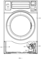
FIG. 1 is a first schematic structural diagram of a gas-fired clothes dryer according to an embodiment of the present application. -
FIG. 2 is a second schematic structural diagram of a gas-fired clothes dryer according to an embodiment of the present application. -
FIG. 3 is a schematic structural diagram of a mounting base in a gas-fired clothes dryer according to an embodiment of the present application. -
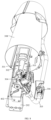
FIG. 4 is a first schematic structural diagram of a mounting base, a mounting frame and a gas-fired heating device in a gas-fired clothes dryer according to an embodiment of the present application. -
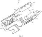
FIG. 5 is a first schematic structural diagram of a mounting frame in a gas-fired clothes dryer according to an embodiment of the present application. -
FIG. 6 is a second schematic structural diagram of a mounting frame in a gas-fired clothes dryer according to an embodiment of the present application. -
FIG. 7 is a second schematic structural diagram of a mounting base, a mounting frame and a gas-fired heating device in a gas-fired clothes dryer according to an embodiment of the present application. -
FIG. 8 is a third schematic structural diagram of a mounting base, a mounting frame and a gas-fired heating device in a gas-fired clothes dryer according to an embodiment of the present application. -
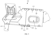
FIG. 9 is a third schematic structural diagram of a mounting frame in a gas-fired clothes dryer according to an embodiment of the present application. - In the drawings:
- 100, housing; 200, mounting base;
- 300, gas-fired heating device; 400, mounting frame;
- 101, operating side surface; 102, maintenance port;
- 103, maintenance cover plate; 201, supporting plate;
- 202, connecting sidewall; 203, first mounting hole;
- 204, first hole section; 205, second hole section;
- 206, third hole section; 207, mounting groove;
- 208, third mounting hole; 301, burner;
- 302, first mounting plate; 303, second mounting plate;
- 304, gas valve; 305, inlet pipe;
- 306, inlet valve; 307, igniter;
- 308, combustion cylinder; 401, first connecting plate;
- 402, second connecting plate; 403, first clamping plate;
- 404, notch; 405, second clamping plate;
- 406, fixed end; 407, movable end;
- 408, accommodating gap; 409, third connecting plate;
- 410, fourth connecting plate; 411, first bent plate;
- 412, second bent plate; 413, opening for gripping.
- First, it should be understood by those skilled in the art that these implementations are only used to explain the technical principles of embodiments of the present application, and are not intended to limit the protection scope of the embodiments of the present application. Those skilled in the art may make adjustment according to their needs, so as to adapt to specific application scenarios.
- Second, it is to be noted that in the description of embodiments of the present application, orientations or positional relationships indicated by the terms "inside", "outside", etc. are based on the orientations or positional relationships shown in the drawings, which is only for the convenience of description, and does not indicate or imply that the device or member must be of a specific orientation, be constructed and operate in a specific orientation, and therefore should not be understood as limiting the embodiments of the present application.
- In addition, it is also to be noted that in the description of embodiments of the present application, unless otherwise expressly specified and defined, the terms "connection" and "connecting" should be understood in a broad sense. For example, "connection" may be a fixed connection, a detachable connection, or an integral connection; "connection" may be a mechanical connection or an electrical connection; "connection" may be a direct connection or an indirect connection through an intermediate medium; and "connection" may be an internal communication of two members. For those of ordinary skill in the art, the specific meanings of the above terms in embodiments of the present application may be understood according to the specific situation.
- In order to make the purposes, technical solutions and advantages of embodiments of the present application clearer, the technical solutions in embodiments of the present application will be described clearly and comprehensively in combination with the drawings in the present application. Obviously, the described embodiments are merely some rather than all of embodiments of the present application. All other embodiments obtained by those of ordinary skill in the art based on embodiments of the present application without creative effort shall fall within the protection scope of the present application.
- A gas-fired clothes dryer in the related art includes a casing, a clothes drying drum, a blower fan and a gas-fired heating device, an accommodating space is provided in the casing, and the clothes drying drum, the blower fan and the gas-fired heating device are all disposed in the accommodating space. The gas-fired heating device includes a gas valve, an inlet pipe, a burner, a combustion cylinder and an igniter, the gas valve is provided with an inlet and an outlet, the inlet is connected with the inlet pipe, and the outlet is connected with the burner. The burner is provided with a combustion-supporting air inlet and a spray nozzle, the combustion-supporting air inlet is arranged to enable the combustion-supporting air to enter the burner, and the combustion-supporting air and the fuel gas are mixed in the burner and then sprayed from the spray nozzle. Both the spray nozzle and the igniter are accommodated in the combustion cylinder, and the fuel gas sprayed from the spray nozzle is ignited by the igniter, heat generated by the combustion of the fuel gas heats the air in the combustion cylinder, and under the action of the blower fan, the heated air enters the clothes drying drum to dry the clothes in the clothes drying drum.
- The fuel gas used in the gas-fired clothes dryer may be natural gas or liquefied gas, and the amount of combustion-supporting air required when natural gas and liquefied gas are combusted is quite different. When the same volume of natural gas and liquefied gas are combusted, the amount of combustion-supporting air required by liquefied gas is about three times the amount of combustion-supporting air required by natural gas, so the burners adapted to natural gas and liquefied gas are different in structure, and the combustion-supporting air inlet on the burner adapted to liquefied gas is larger than that on the burner adapted to natural gas.
- When the gas-fired clothes dryer leaves factory, the burner mounted in the casing is adapted to natural gas, and if the user wants to use liquefied gas, the burner needs to be replaced. For replacing the burner, it is necessary to open the casing and move the clothes drying drum out of the accommodating space before replacing the burner, and the process is cumbersome.
- This embodiment provides a gas-fired clothes dryer, where a mounting base is disposed in a housing, a gas-fired heating device is connected to a mounting frame, the mounting frame is detachably connected to the mounting base, and a maintenance port is provided on the housing, and the maintenance port directly faces the mounting base. For replacing a burner, the mounting frame is detached from the mounting base through the maintenance port, and then the gas-fired heating device and the mounting frame are moved out of the housing from the maintenance port to replace the burner on the gas-fired heating device, and the whole process is convenient and fast.
- The principles and features of embodiments of the present application are described below with reference to the drawings. The cited examples are only used to explain the embodiments of the present application, and are not used to limit the scope of the embodiments of the present application.
- As shown in
FIG. 1 , a gas-fired clothes dryer provided in embodiments of the present application includes ahousing 100, a gas-firedheating device 300 and a mountingframe 400. An accommodating space is provided in thehousing 100, and a mountingbase 200 is disposed in the accommodating space. As shown inFIG. 2 , thehousing 100 has an operatingside surface 101. The operatingside surface 101 is disposed toward the user. A maintenance port 102 (as shown inFIG. 1 ) is provided on the operatingside surface 101, and themaintenance port 102 is connected with the accommodation space and directly faces the mountingbase 200. - With continued reference to
FIG. 1 , the gas-firedheating device 300 is connected to the mountingframe 400. The gas-firedheating device 300 includes aburner 301, and theburner 301 is detachably connected to the mountingframe 400. The mountingframe 400 is detachably connected to the mountingbase 200. Themaintenance port 102 also directly faces the gas-firedheating device 300 and the mountingframe 400, and the gas-firedheating device 300 and the mountingframe 400 can pass through themaintenance port 102. - When the
burner 301 needs to be replaced, the mountingframe 400 is detached from the mountingbase 200 through themaintenance port 102, then the gas-firedheating device 300 and the mountingframe 400 are moved out of thehousing 100 from themaintenance port 102. Theburner 301 is detached from the mountingframe 400, and theburner 301 to be used is mounted on the mountingframe 400. Then the mountingframe 400 and the gas-firedheating device 300 are moved from themaintenance port 102 into the accommodating space, and the mountingframe 400 is assembled on the mountingbase 200 through themaintenance port 102. - In the process of replacing the
burner 301, there is no need to open a casing and remove a clothes drying drum, the whole process is convenient and fast, the maintenance time is saved and the maintenance cost is reduced. - The mounting
base 200 described above may be disposed on an inner sidewall of thehousing 100 or at a bottom of the accommodating space. With continued reference toFIG. 1 , in the implementation that the mountingbase 200 is disposed at the bottom of the accommodating space, a fixing plate may be disposed at a bottom of the mountingbase 200. The fixing plate may be parallel to the horizontal plane, and a fixing hole may be disposed on the fixing plate, and a fastening bolt is connected with thehousing 100 after passing through the fixing hole, so that the base may be detachably connected to thehousing 100. Of course, the mountingbase 200 may also be welded on thehousing 100. As shown inFIG. 3 andFIG.4 , a supportingplate 201 may be provided on a top of the mountingbase 200. The mountingbase 200 is also provided with a connectingsidewall 202. The connectingsidewall 202 is located below the supportingplate 201, and the connectingsidewall 202 is adjacent to the supportingplate 201, and the connectingsidewall 202 is disposed toward themaintenance port 102. As shown inFIG. 5 andFIG. 6 , the mountingframe 400 may include a first connectingplate 401 and a second connectingplate 402. The first connectingplate 401 is parallel to the supportingplate 201, and the second connectingplate 402 is disposed at a bottom of the first connectingplate 401. As shown inFIG. 7 andFIG. 8 , the first connectingplate 401 is attached to the supportingplate 201, and the second connectingplate 402 is attached to the connectingsidewall 202, and the fastening bolt is connected with the connectingsidewall 202 after penetrating the second connectingplate 402. - For replacing the
burner 301, the fastening bolt is loosened, so that the second connectingplate 402 is detached from the connectingsidewall 202. Then the mountingframe 400 is held by hand and moved toward themaintenance port 102 to detach the mountingframe 400 from the mountingbase 200 and move the mountingframe 400 out of themaintenance port 102. Since the gas-firedheating device 300 is connected to the mountingframe 400, the gas-firedheating device 300 is moved out of themaintenance port 102 together with the mountingframe 400, so as to facilitate the replacement of theburner 301 by maintenance personnel. After the replacement is finished, the mountingframe 400 is mounted on the mountingbase 200 from themaintenance port 102. - In the implementation that the mounting
base 200 is disposed on the inner sidewall of thehousing 100, the mountingbase 200 may have a second sidewall and a third sidewall. The second sidewall is away from the inner sidewall of thehousing 100 where the mountingbase 200 is located, the third sidewall is adjacent to the second sidewall, and the third sidewall faces themaintenance port 102. The mountingframe 400 may include a first connectingplate 401 and a second connectingplate 402. The first connectingplate 401 is adjacent to the second connectingplate 402, the first connectingplate 401 is attached to the second sidewall, and the second connectingplate 402 is attached to the third sidewall, and the fastening bolt is connected with the third sidewall after penetrating the second connectingplate 402. - With continued reference to
FIG. 6 , in the implementation that the mountingbase 200 is disposed at the bottom of the accommodating space, afirst clamping plate 403 may also be provided at the bottom of the first connectingplate 401. Thefirst clamping plate 403 is perpendicular to the first connectingplate 401, and anotch 404 is provided at an end of thefirst clamping plate 403 away from the second connecting plate 402 (as shown inFIG. 9 ), and a top end of thenotch 404 extends to the bottom of the first connectingplate 401. With continued reference toFIG. 3 , the supportingplate 201 is provided with a first mountinghole 203, the first mountinghole 203 is arranged to allow thefirst clamping plate 403 to pass through, and the supportingplate 201 is clamped in the notch 404 (as shown inFIG. 4 ). - A width of the
notch 404 described above in a direction perpendicular to the first connectingplate 401 is equal to a thickness of the supportingplate 201, so the supportingplate 201 may be just clamped in thenotch 404, so that after the supportingplate 201 is clamped in thenotch 404, it is not easy for a shake to occur between the first connectingplate 401 and the supportingplate 201, thereby making the connection between the mountingframe 400 and the mountingbase 200 more stable. - For assembling the mounting
frame 400 and the mountingbase 200, thefirst clamping plate 403 is first moved above the first mountinghole 203, and then the mountingframe 400 is moved downward, so that thefirst clamping plate 403 is inserted into the first mountinghole 203 from top to bottom. After that, the mountingframe 400 is moved away from themaintenance port 102, so that the supportingplate 201 is clamped in thenotch 404, thereby realizing the connection between the first connectingplate 401 and the supportingplate 201 and making the connection between the mountingframe 400 and the mountingbase 200 more stable. - For detaching the mounting
frame 400 from the mountingbase 200, the mountingframe 400 is moved toward themaintenance port 102 to detach the supportingplate 201 from thenotch 404, and then the mountingframe 400 is moved upward to detach thefirst clamping plate 403 from the first mountinghole 203, thereby detaching the mountingframe 400 from the mountingbase 200, which is convenient and fast. - With continued reference to
FIG. 3 , further, the first mountinghole 203 may include a first hole section 204, asecond hole section 205 and a third hole section 206. The first hole section 204, thesecond hole section 205 and the third hole section 206 are connected with each other, and distances between the first hole section 204 and the second connectingplate 402, between thesecond hole section 205 and the second connectingplate 402, and between the third hole section 206 and the second connectingplate 402 increase in sequence. In a direction perpendicular to thefirst clamping plate 403, a width of the third hole section 206 is equal to a thickness of thefirst clamping plate 403 so as to clamp thefirst clamping plate 403 in the third hole section 206. A width of the first hole section 204 is greater than a width of the third hole section 206, that is, the width of the first hole section 204 is greater than the thickness of thefirst clamping plate 403, and thus thefirst clamping plate 403 may be inserted into the first hole section 204 more easily. A width of thesecond hole section 205 decreases in a direction from the first hole section 204 to the third hole section 206, and a sidewall of thesecond hole section 205 may guide thefirst clamping plate 403, so that thefirst clamping plate 403 may move into the third hole section 206 along the sidewall of thesecond hole section 205 after be inserted into the first hole section 204, which makes the assembly of the mountingframe 400 and the mountingbase 200 more convenient and fast. - With continued reference to
FIG. 6 , in the implementation that the mountingbase 200 is disposed at the bottom of the accommodation space, asecond clamping plate 405 may also be provided at the bottom of the first connectingplate 401. Thesecond clamping plate 405 has a fixedend 406 and amovable end 407. Thefixed end 406 is connected with the first connectingplate 401, themovable end 407 extends away from the second connectingplate 402, and there is anaccommodating gap 408 between thesecond clamping plate 405 and the first connectingplate 401. The supportingplate 201 is provided with a second mounting hole, the second mounting hole is arranged to allow thesecond clamping plate 405 to pass through, and the supportingplate 201 is clamped in theaccommodating gap 408. - For assembling the mounting
frame 400 and the mountingbase 200, thesecond clamping plate 405 is first moved above the second mounting hole, and then the mountingframe 400 is moved downward, so that thesecond clamping plate 405 is inserted into the second mounting hole from top to bottom. After that, the mountingframe 400 is moved toward a direction away from themaintenance port 102, so that the supportingplate 201 is clamped in the accommodating gap 408 (as shown inFIG. 4 ), thereby realizing the connection between the first connectingplate 401 and the supportingplate 201 and making the connection between the mountingframe 400 and the mountingbase 200 more stable. - For detaching the mounting
frame 400 from the mountingbase 200, the mountingframe 400 is moved toward themaintenance port 102 to move the supportingplate 201 out of theaccommodating gap 408, and then the mountingframe 400 is moved upward to move thesecond clamping plate 405 out of the second mounting hole, so as to detach the mountingframe 400 from the mountingbase 200, which is convenient and fast. - With continued reference to
FIG. 3 , further, part of the first connectingplate 401 is concave downward to form a mountinggroove 207, and a rabbet of the mountinggroove 207 forms a second mounting hole. Thesecond clamping plate 405 may be accommodated in the mountinggroove 207, and a groove wall of the mountinggroove 207 away from the second connectingplate 402 is provided with athird mounting hole 208. Thethird mounting hole 208 is located below the first connectingplate 401, a top end of the third mountinghole 208 may extend to the bottom of the first connectingplate 401, and the third mountinghole 208 is arranged to allow thesecond clamping plate 405 to pass through. - With continued reference to
FIG. 6 andFIG. 9 , thesecond clamping plate 405 described above may extend in a wave shape, and thesecond clamping plate 405 may have a wave trough and a wave peak. Thesecond clamping plate 405 at the wave peak may abut against a bottom of the supportingplate 201 to reduce a contact area between thesecond clamping plate 405 and the supportingplate 201, thereby reducing the friction between thesecond clamping plate 405 and the supportingplate 201, so that for mounting/detaching the mountingframe 400 on/from the mountingbase 200, less external force is needed, and it is easier to assemble the mountingframe 400 and mountingbase 200. - With continued reference to
FIG. 2 , in some embodiments, amaintenance cover plate 103 may be disposed on the operatingside surface 101. Themaintenance cover plate 103 is arranged to close themaintenance port 102, and themaintenance cover plate 103 is detachably connected with thehousing 100. For example, themaintenance cover plate 103 may be connected with thehousing 100 by a fastening bolt. - When the
burner 301 needs to be replaced, themaintenance cover plate 103 is opened to expose themaintenance port 102, and then the mountingframe 400 is detached from the mountingbase 200 through themaintenance port 102, and theburner 301 is replaced. - With continued reference to
FIG. 8 , in some embodiments, theburner 301 has afirst mounting plate 302 and asecond mounting plate 303, and a plane where the first mountingplate 302 is located and a plane where thesecond mounting plate 303 is located are coplanar. With continued reference toFIG. 5 , the mountingframe 400 further includes a third connectingplate 409 and a fourth connectingplate 410. The third connectingplate 409 and the fourth connectingplate 410 are parallel and spaced apart from one another on a top of the first connectingplate 401, and are both perpendicular to the first connectingplate 401. A top end of the third connectingplate 409 is bent toward the fourth connectingplate 410 to form a firstbent plate 411, and the first mountingplate 302 is detachably connected with the firstbent plate 411. For example, the first mountingplate 302 and the firstbent plate 411 may be connected by a fastening bolt. A top end of the fourth connectingplate 410 is bent toward the third connectingplate 409 to form a secondbent plate 412, and thesecond mounting plate 303 is detachably connected with the secondbent plate 412. For example, thesecond mounting plate 303 and the secondbent plate 412 may be connected by a fastening bolt. - Further, the third connecting
plate 409 and/or the fourth connectingplate 410 may be provided with a gripping portion, and the gripping portion is arranged to be gripped by a hand of the maintenance personnel. For example, the gripping portion may include an opening for gripping 413 or a handle for gripping, and the handle for gripping may be disposed outside the third connectingplate 409 and/or the fourth connectingplate 410. With continued reference toFIG. 4 to FIG. 7 , the opening for gripping 413 may be provided on the third connectingplate 409 and/or the fourth connectingplate 410. For detaching the mountingframe 400, the fingers of the maintenance personnel are inserted into the opening for gripping 413 and pull the mountingframe 400 toward themaintenance port 102, so that the mountingframe 400 may be detached from the mountingbase 200 more easily. For assembling the mountingframe 400 and the mountingbase 200, the fingers of the maintenance personnel are inserted into the opening for gripping 413 and push the mountingframe 400 away from themaintenance port 102, so that it is easy to assemble the mountingframe 400 and the mountingbase 200. - With continued reference to
FIG. 7 , the gas-firedheating device 300 may further include agas valve 304, aninlet pipe 305, anigniter 307 and acombustion cylinder 308. Thegas valve 304 is provided with an inlet and an outlet, the inlet is connected with theinlet pipe 305, and the outlet is connected with theburner 301. Theinlet pipe 305 may be provided with aninlet valve 306, and the fuel gas enters thegas valve 304 from theinlet pipe 305, and enters theburner 301 from thegas valve 304. Theburner 301 has a spray nozzle, and the fuel gas is sprayed from the spray nozzle. Theigniter 307 is disposed near the spray nozzle, and both theigniter 307 and the spray nozzle are accommodated in thecombustion cylinder 308. Theigniter 307 is arranged to ignite the fuel gas sprayed from the spray nozzle, and heat generated by the combustion of the fuel gas heats the air in thecombustion cylinder 308. - In addition to the detachable connection between the
burner 301 and the mountingframe 400, thegas valve 304, theigniter 307 and thecombustion cylinder 308 may all be detachably connected with the mountingframe 400, and when thegas valve 304, theigniter 307 or thecombustion cylinder 308 is damaged, it is convenient to replace the damaged part. - To sum up, in the gas-fired clothes dryer according to the embodiments of the present application, the mounting
base 200 is disposed in thehousing 100, the gas-firedheating device 300 is connected to the mountingframe 400, and the mountingframe 400 is detachably connected to the mountingbase 200. In addition, thehousing 100 is provided with amaintenance port 102, themaintenance port 102 directly faces the mountingbase 200, and themaintenance port 102 is arranged to allow the gas-firedheating device 300 and the mountingframe 400 to pass through. Through the above arrangement, for replacing theburner 301, the mountingframe 400 is detached from the mountingbase 200 through themaintenance port 102, and then the gas-firedheating device 300 and the mountingframe 400 are moved out of thehousing 100 from themaintenance port 102 to replace theburner 301 on the gas-firedheating device 300, making the whole process convenient and fast, saving the maintenance time and reducing the maintenance cost. - Finally, it should be noted that the above embodiments are only used to illustrate the technical solutions of the present application, but not to limit them. Although the present application has been illustrated in detail with reference to the aforementioned embodiments, it should be understood by those ordinarily skilled in the art that they may still make modifications to the technical solutions recorded in the aforementioned embodiments, or make equivalent substitutions to some or all of the technical features therein. However, these modifications or substitutions do not make the essence of corresponding technical solutions deviate from the scope of the technical solutions of the embodiments of the present application.
Claims (10)
- A gas-fired clothes dryer, comprising: a housing, a gas-fired heating device and a mounting frame, wherein the housing has an operating side surface, the operating side surface is disposed toward a user, the operating side surface is provided with a maintenance port, and the maintenance port is arranged to allow the gas-fired heating device and the mounting frame to pass through; and
a mounting base is disposed in the housing, the mounting base directly faces the maintenance port, the mounting frame is detachably connected to the mounting base, and the gas-fired heating device is connected to the mounting frame. - The gas-fired clothes dryer according to claim 1, wherein a supporting plate is provided on a top of the mounting base, and the mounting base also has a connecting sidewall, the connecting sidewall is located below the supporting plate, the connecting sidewall is adjacent to the supporting plate, and the connecting sidewall is disposed toward the maintenance port; and
the mounting frame comprises a first connecting plate and a second connecting plate, the first connecting plate is parallel to the supporting plate, the second connecting plate is disposed at a bottom of the first connecting plate, the first connecting plate is attached to the supporting plate, the second connecting plate is attached to the connecting sidewall, and a fastening bolt is connected with the connecting sidewall after penetrating the second connecting plate. - The gas-fired clothes dryer according to claim 2, wherein a first clamping plate is disposed at the bottom of the first connecting plate, the first clamping plate is perpendicular to the first connecting plate, and a notch is provided at an end of the first clamping plate away from the second connecting plate, and the notch extends to the first connecting plate; and
the supporting plate is provided with a first mounting hole, the first mounting hole is arranged to allow the first clamping plate to pass through, and the supporting plate is clamped in the notch. - The gas-fired clothes dryer according to claim 3, wherein the first mounting hole comprises a first hole section, a second hole section and a third hole section, the first hole section, the second hole section and the third hole section are connected with each other, and distances between the first hole section and the second connecting plate, between the second hole section and the second connecting plate, and between the third hole section and the second connecting plate increase in sequence; and
in a direction perpendicular to the first clamping plate, a width of the third hole section is equal to a thickness of the first clamping plate, a width of the first hole section is greater than the width of the third hole section, and a width of the second hole section decreases in a direction from the first hole section to the third hole section. - The gas-fired clothes dryer according to claim 3 or 4, wherein a width of the notch in a direction perpendicular to the first connecting plate is equal to a thickness of the supporting plate.
- The gas-fired clothes dryer according to claim 2, wherein a second clamping plate is disposed at the bottom of the first connecting plate, the second clamping plate has a fixed end and a movable end, the fixed end is connected with the first connecting plate, and the movable end extends away from the second connecting plate, and there is an accommodating gap between the second clamping plate and the first connecting plate; and
the supporting plate is provided with a second mounting hole, the second mounting hole is arranged to allow the second clamping plate to pass through, and the supporting plate is clamped in the accommodating gap. - The gas-fired clothes dryer according to claim 6, wherein the first connecting plate is concave downward to form a mounting groove, and a rabbet of the mounting groove forms the second mounting hole, and the second clamping plate is capable of being accommodated in the mounting groove, and a groove wall of the mounting groove away from the second connecting plate is provided with a third mounting hole, and the third mounting hole is arranged to allow the second clamping plate to pass through.
- The gas-fired clothes dryer according to any one of claims 1 to 7, wherein a maintenance cover plate is disposed on the operating side surface, the maintenance cover plate is detachably connected with the housing, and the maintenance cover plate is arranged to close the maintenance port.
- The gas-fired clothes dryer according to any one of claims 2 to 7, wherein the gas-fired heating device comprises a burner, and the burner is detachably connected to the mounting frame.
- The gas-fired clothes dryer according to claim 9, wherein the burner has a first mounting plate and a second mounting plate, and a plane where the first mounting plate is located and a plane where the second mounting plate is located are coplanar; and
the mounting frame further comprises a third connecting plate and a fourth connecting plate, the third connecting plate and the fourth connecting plate are parallel and spaced apart from one another on a top of the first connecting plate, and are perpendicular to the first connecting plate, and a top end of the third connecting plate is bent toward the fourth connecting plate to form a first bent plate, and the first mounting plate is detachably connected with the first bent plate; and a top end of the fourth connecting plate is bent toward the third connecting plate to form a second bent plate, and the second mounting plate is detachably connected with the second bent plate.
Applications Claiming Priority (2)
| Application Number | Priority Date | Filing Date | Title |
|---|---|---|---|
| CN202210182644.1A CN114622392B (en) | 2022-02-25 | 2022-02-25 | Gas dryer |
| PCT/CN2023/072693 WO2023160308A1 (en) | 2022-02-25 | 2023-01-17 | Gas clothes dryer |
Publications (3)
| Publication Number | Publication Date |
|---|---|
| EP4484636A1 true EP4484636A1 (en) | 2025-01-01 |
| EP4484636A4 EP4484636A4 (en) | 2025-04-30 |
| EP4484636B1 EP4484636B1 (en) | 2026-07-22 |
Family
ID=81899448
Family Applications (1)
| Application Number | Title | Priority Date | Filing Date |
|---|---|---|---|
| EP23758933.8A Active EP4484636B1 (en) | 2022-02-25 | 2023-01-17 | Gas clothes dryer |
Country Status (4)
| Country | Link |
|---|---|
| US (1) | US20240410106A1 (en) |
| EP (1) | EP4484636B1 (en) |
| CN (1) | CN114622392B (en) |
| WO (1) | WO2023160308A1 (en) |
Families Citing this family (1)
| Publication number | Priority date | Publication date | Assignee | Title |
|---|---|---|---|---|
| CN114622392B (en) * | 2022-02-25 | 2026-06-16 | 青岛海尔洗衣机有限公司 | Gas dryer |
Family Cites Families (11)
| Publication number | Priority date | Publication date | Assignee | Title |
|---|---|---|---|---|
| US5379750A (en) * | 1993-09-16 | 1995-01-10 | Carrier Corporation | Burner mounting assembly for gas furnace |
| KR100578325B1 (en) * | 2001-09-05 | 2006-05-11 | 주식회사 엘지이아이 | Burner Support Device of Dryer |
| KR100583242B1 (en) * | 2004-08-14 | 2006-05-25 | (주)제이엠씨텍 | Clothes dryer with gas switching device |
| KR100762341B1 (en) * | 2006-09-07 | 2007-10-02 | 주식회사 대우일렉트로닉스 | Gas heater and dryer having same |
| CA2619213A1 (en) * | 2007-08-14 | 2009-02-14 | Johnson Controls Technology Company | Furnace burner box |
| US8069582B2 (en) * | 2007-12-27 | 2011-12-06 | Daewoo Electronics Corporation | Dryer |
| CN105443517B (en) * | 2014-08-04 | 2017-12-26 | 无锡小天鹅股份有限公司 | Dryer, heating component and support for dryer |
| CN209144528U (en) * | 2018-09-07 | 2019-07-23 | 青岛海尔滚筒洗衣机有限公司 | A kind of fuel gas dryer |
| CN111336517A (en) * | 2018-12-18 | 2020-06-26 | 无锡小天鹅电器有限公司 | Nozzle assembly of burner, burner and clothes dryer |
| CN114075773B (en) * | 2020-08-21 | 2023-06-30 | 青岛胶州海尔洗涤电器有限公司 | Burner and gas clothes dryer |
| CN114622392B (en) * | 2022-02-25 | 2026-06-16 | 青岛海尔洗衣机有限公司 | Gas dryer |
-
2022
- 2022-02-25 CN CN202210182644.1A patent/CN114622392B/en active Active
-
2023
- 2023-01-17 WO PCT/CN2023/072693 patent/WO2023160308A1/en not_active Ceased
- 2023-01-17 EP EP23758933.8A patent/EP4484636B1/en active Active
-
2024
- 2024-08-19 US US18/809,214 patent/US20240410106A1/en active Pending
Also Published As
| Publication number | Publication date |
|---|---|
| CN114622392B (en) | 2026-06-16 |
| EP4484636A4 (en) | 2025-04-30 |
| CN114622392A (en) | 2022-06-14 |
| EP4484636B1 (en) | 2026-07-22 |
| US20240410106A1 (en) | 2024-12-12 |
| WO2023160308A1 (en) | 2023-08-31 |
Similar Documents
| Publication | Publication Date | Title |
|---|---|---|
| US20240410106A1 (en) | Gas-fired clothes dryer | |
| EP4484637A1 (en) | Gas heating apparatus and gas clothes dryer | |
| CN108626878B (en) | Gas water heater | |
| CN214179146U (en) | Detachable heat-not-burn electronic cigarette | |
| TWI578911B (en) | Barbeque stove | |
| CN110145871A (en) | Combustion chamber structure and gas water heater | |
| JP6546478B2 (en) | Hot pot | |
| CN116556031B (en) | A combustion chamber structure and a gas-fired clothes dryer | |
| CN112617628B (en) | Baking oven | |
| JPH1019209A (en) | Burners for gas appliances | |
| CN209144528U (en) | A kind of fuel gas dryer | |
| KR101215688B1 (en) | Condensing boiler heat exchanger | |
| CN215637348U (en) | Gas stove | |
| WO2023214730A1 (en) | Gas burner for camping | |
| CN209386564U (en) | Combustor outer casing and water heater | |
| CN218864223U (en) | Ignition device and gas water heater | |
| CN115614750A (en) | Burners and Gas Water Heaters | |
| CN219713350U (en) | Furnace end | |
| CN223050221U (en) | Combustion assembly, gas equipment and cover plate | |
| CN113405124A (en) | Gas stove | |
| CN216203347U (en) | Gas heat exchanger and combustion structure | |
| CN223709710U (en) | Foldable infrared gas double-end furnace | |
| CN223448657U (en) | Gas equipment and gas water heater | |
| CN111609425A (en) | Multifunctional outdoor stove | |
| CN221403488U (en) | Heat insulation end plate structure |
Legal Events
| Date | Code | Title | Description |
|---|---|---|---|
| STAA | Information on the status of an ep patent application or granted ep patent |
Free format text: STATUS: THE INTERNATIONAL PUBLICATION HAS BEEN MADE |
|
| PUAI | Public reference made under article 153(3) epc to a published international application that has entered the european phase |
Free format text: ORIGINAL CODE: 0009012 |
|
| STAA | Information on the status of an ep patent application or granted ep patent |
Free format text: STATUS: REQUEST FOR EXAMINATION WAS MADE |
|
| 17P | Request for examination filed |
Effective date: 20240819 |
|
| AK | Designated contracting states |
Kind code of ref document: A1 Designated state(s): AL AT BE BG CH CY CZ DE DK EE ES FI FR GB GR HR HU IE IS IT LI LT LU LV MC ME MK MT NL NO PL PT RO RS SE SI SK SM TR |
|
| A4 | Supplementary search report drawn up and despatched |
Effective date: 20250401 |
|
| RIC1 | Information provided on ipc code assigned before grant |
Ipc: D06F 58/26 20060101ALI20250326BHEP Ipc: D06F 58/02 20060101AFI20250326BHEP |
|
| DAV | Request for validation of the european patent (deleted) | ||
| DAX | Request for extension of the european patent (deleted) | ||
| GRAP | Despatch of communication of intention to grant a patent |
Free format text: ORIGINAL CODE: EPIDOSNIGR1 |
|
| STAA | Information on the status of an ep patent application or granted ep patent |
Free format text: STATUS: GRANT OF PATENT IS INTENDED |
|
| GRAS | Grant fee paid |
Free format text: ORIGINAL CODE: EPIDOSNIGR3 |
|
| GRAA | (expected) grant |
Free format text: ORIGINAL CODE: 0009210 |
|
| STAA | Information on the status of an ep patent application or granted ep patent |
Free format text: STATUS: THE PATENT HAS BEEN GRANTED |
|
| INTG | Intention to grant announced |
Effective date: 20260527 |
|
| AK | Designated contracting states |
Kind code of ref document: B1 Designated state(s): AL AT BE BG CH CY CZ DE DK EE ES FI FR GB GR HR HU IE IS IT LI LT LU LV MC ME MK MT NL NO PL PT RO RS SE SI SK SM TR |
|
| REG | Reference to a national code |
Ref country code: CH Ref legal event code: F10 Free format text: ST27 STATUS EVENT CODE: U-0-0-F10-F00 (AS PROVIDED BY THE NATIONAL OFFICE) Effective date: 20260722 Ref country code: GB Ref legal event code: FG4D |
|
| REG | Reference to a national code |
Ref country code: IE Ref legal event code: FG4D |
|
| REG | Reference to a national code |
Ref country code: DE Ref legal event code: R096 Ref document number: 602023020262 Country of ref document: DE |