EP4484587A1 - Steel pipe, component for vehicles, method for producing steel pipe and method for producing component for vehicles - Google Patents
Steel pipe, component for vehicles, method for producing steel pipe and method for producing component for vehicles Download PDFInfo
- Publication number
- EP4484587A1 EP4484587A1 EP23756499.2A EP23756499A EP4484587A1 EP 4484587 A1 EP4484587 A1 EP 4484587A1 EP 23756499 A EP23756499 A EP 23756499A EP 4484587 A1 EP4484587 A1 EP 4484587A1
- Authority
- EP
- European Patent Office
- Prior art keywords
- less
- content
- steel tube
- further preferably
- oxide coating
- Prior art date
- Legal status (The legal status is an assumption and is not a legal conclusion. Google has not performed a legal analysis and makes no representation as to the accuracy of the status listed.)
- Pending
Links
Images
Classifications
-
- C—CHEMISTRY; METALLURGY
- C22—METALLURGY; FERROUS OR NON-FERROUS ALLOYS; TREATMENT OF ALLOYS OR NON-FERROUS METALS
- C22C—ALLOYS
- C22C38/00—Ferrous alloys, e.g. steel alloys
- C22C38/04—Ferrous alloys, e.g. steel alloys containing manganese
-
- B—PERFORMING OPERATIONS; TRANSPORTING
- B21—MECHANICAL METAL-WORKING WITHOUT ESSENTIALLY REMOVING MATERIAL; PUNCHING METAL
- B21D—WORKING OR PROCESSING OF SHEET METAL OR METAL TUBES, RODS OR PROFILES WITHOUT ESSENTIALLY REMOVING MATERIAL; PUNCHING METAL
- B21D53/00—Making other particular articles
- B21D53/88—Making other particular articles other parts for vehicles, e.g. cowlings, mudguards
-
- C—CHEMISTRY; METALLURGY
- C21—METALLURGY OF IRON
- C21D—MODIFYING THE PHYSICAL STRUCTURE OF FERROUS METALS; GENERAL DEVICES FOR HEAT TREATMENT OF FERROUS OR NON-FERROUS METALS OR ALLOYS; MAKING METAL MALLEABLE, e.g. BY DECARBURISATION OR TEMPERING
- C21D1/00—General methods or devices for heat treatment, e.g. annealing, hardening, quenching or tempering
- C21D1/18—Hardening; Quenching with or without subsequent tempering
-
- C—CHEMISTRY; METALLURGY
- C21—METALLURGY OF IRON
- C21D—MODIFYING THE PHYSICAL STRUCTURE OF FERROUS METALS; GENERAL DEVICES FOR HEAT TREATMENT OF FERROUS OR NON-FERROUS METALS OR ALLOYS; MAKING METAL MALLEABLE, e.g. BY DECARBURISATION OR TEMPERING
- C21D1/00—General methods or devices for heat treatment, e.g. annealing, hardening, quenching or tempering
- C21D1/18—Hardening; Quenching with or without subsequent tempering
- C21D1/25—Hardening, combined with annealing between 300 degrees Celsius and 600 degrees Celsius, i.e. heat refining ("Vergüten")
-
- C—CHEMISTRY; METALLURGY
- C21—METALLURGY OF IRON
- C21D—MODIFYING THE PHYSICAL STRUCTURE OF FERROUS METALS; GENERAL DEVICES FOR HEAT TREATMENT OF FERROUS OR NON-FERROUS METALS OR ALLOYS; MAKING METAL MALLEABLE, e.g. BY DECARBURISATION OR TEMPERING
- C21D1/00—General methods or devices for heat treatment, e.g. annealing, hardening, quenching or tempering
- C21D1/26—Methods of annealing
-
- C—CHEMISTRY; METALLURGY
- C21—METALLURGY OF IRON
- C21D—MODIFYING THE PHYSICAL STRUCTURE OF FERROUS METALS; GENERAL DEVICES FOR HEAT TREATMENT OF FERROUS OR NON-FERROUS METALS OR ALLOYS; MAKING METAL MALLEABLE, e.g. BY DECARBURISATION OR TEMPERING
- C21D6/00—Heat treatment of ferrous alloys
- C21D6/005—Heat treatment of ferrous alloys containing Mn
-
- C—CHEMISTRY; METALLURGY
- C21—METALLURGY OF IRON
- C21D—MODIFYING THE PHYSICAL STRUCTURE OF FERROUS METALS; GENERAL DEVICES FOR HEAT TREATMENT OF FERROUS OR NON-FERROUS METALS OR ALLOYS; MAKING METAL MALLEABLE, e.g. BY DECARBURISATION OR TEMPERING
- C21D8/00—Modifying the physical properties of ferrous metals or ferrous alloys by deformation combined with, or followed by, heat treatment
- C21D8/10—Modifying the physical properties of ferrous metals or ferrous alloys by deformation combined with, or followed by, heat treatment during manufacturing of tubular bodies
-
- C—CHEMISTRY; METALLURGY
- C21—METALLURGY OF IRON
- C21D—MODIFYING THE PHYSICAL STRUCTURE OF FERROUS METALS; GENERAL DEVICES FOR HEAT TREATMENT OF FERROUS OR NON-FERROUS METALS OR ALLOYS; MAKING METAL MALLEABLE, e.g. BY DECARBURISATION OR TEMPERING
- C21D9/00—Heat treatment, e.g. annealing, hardening, quenching or tempering, adapted for particular articles; Furnaces therefor
- C21D9/08—Heat treatment, e.g. annealing, hardening, quenching or tempering, adapted for particular articles; Furnaces therefor for tubular bodies or pipes
-
- C—CHEMISTRY; METALLURGY
- C21—METALLURGY OF IRON
- C21D—MODIFYING THE PHYSICAL STRUCTURE OF FERROUS METALS; GENERAL DEVICES FOR HEAT TREATMENT OF FERROUS OR NON-FERROUS METALS OR ALLOYS; MAKING METAL MALLEABLE, e.g. BY DECARBURISATION OR TEMPERING
- C21D9/00—Heat treatment, e.g. annealing, hardening, quenching or tempering, adapted for particular articles; Furnaces therefor
- C21D9/08—Heat treatment, e.g. annealing, hardening, quenching or tempering, adapted for particular articles; Furnaces therefor for tubular bodies or pipes
- C21D9/085—Cooling or quenching
-
- C—CHEMISTRY; METALLURGY
- C21—METALLURGY OF IRON
- C21D—MODIFYING THE PHYSICAL STRUCTURE OF FERROUS METALS; GENERAL DEVICES FOR HEAT TREATMENT OF FERROUS OR NON-FERROUS METALS OR ALLOYS; MAKING METAL MALLEABLE, e.g. BY DECARBURISATION OR TEMPERING
- C21D9/00—Heat treatment, e.g. annealing, hardening, quenching or tempering, adapted for particular articles; Furnaces therefor
- C21D9/50—Heat treatment, e.g. annealing, hardening, quenching or tempering, adapted for particular articles; Furnaces therefor for welded joints
-
- C—CHEMISTRY; METALLURGY
- C21—METALLURGY OF IRON
- C21D—MODIFYING THE PHYSICAL STRUCTURE OF FERROUS METALS; GENERAL DEVICES FOR HEAT TREATMENT OF FERROUS OR NON-FERROUS METALS OR ALLOYS; MAKING METAL MALLEABLE, e.g. BY DECARBURISATION OR TEMPERING
- C21D9/00—Heat treatment, e.g. annealing, hardening, quenching or tempering, adapted for particular articles; Furnaces therefor
- C21D9/50—Heat treatment, e.g. annealing, hardening, quenching or tempering, adapted for particular articles; Furnaces therefor for welded joints
- C21D9/505—Cooling thereof
-
- C—CHEMISTRY; METALLURGY
- C22—METALLURGY; FERROUS OR NON-FERROUS ALLOYS; TREATMENT OF ALLOYS OR NON-FERROUS METALS
- C22C—ALLOYS
- C22C38/00—Ferrous alloys, e.g. steel alloys
- C22C38/02—Ferrous alloys, e.g. steel alloys containing silicon
-
- C—CHEMISTRY; METALLURGY
- C23—COATING METALLIC MATERIAL; COATING MATERIAL WITH METALLIC MATERIAL; CHEMICAL SURFACE TREATMENT; DIFFUSION TREATMENT OF METALLIC MATERIAL; COATING BY VACUUM EVAPORATION, BY SPUTTERING, BY ION IMPLANTATION OR BY CHEMICAL VAPOUR DEPOSITION, IN GENERAL; INHIBITING CORROSION OF METALLIC MATERIAL OR INCRUSTATION IN GENERAL
- C23C—COATING METALLIC MATERIAL; COATING MATERIAL WITH METALLIC MATERIAL; SURFACE TREATMENT OF METALLIC MATERIAL BY DIFFUSION INTO THE SURFACE, BY CHEMICAL CONVERSION OR SUBSTITUTION; COATING BY VACUUM EVAPORATION, BY SPUTTERING, BY ION IMPLANTATION OR BY CHEMICAL VAPOUR DEPOSITION, IN GENERAL
- C23C2/00—Hot-dipping or immersion processes for applying the coating material in the molten state without affecting the shape; Apparatus therefor
- C23C2/04—Hot-dipping or immersion processes for applying the coating material in the molten state without affecting the shape; Apparatus therefor characterised by the coating material
- C23C2/12—Aluminium or alloys based thereon
-
- C—CHEMISTRY; METALLURGY
- C23—COATING METALLIC MATERIAL; COATING MATERIAL WITH METALLIC MATERIAL; CHEMICAL SURFACE TREATMENT; DIFFUSION TREATMENT OF METALLIC MATERIAL; COATING BY VACUUM EVAPORATION, BY SPUTTERING, BY ION IMPLANTATION OR BY CHEMICAL VAPOUR DEPOSITION, IN GENERAL; INHIBITING CORROSION OF METALLIC MATERIAL OR INCRUSTATION IN GENERAL
- C23C—COATING METALLIC MATERIAL; COATING MATERIAL WITH METALLIC MATERIAL; SURFACE TREATMENT OF METALLIC MATERIAL BY DIFFUSION INTO THE SURFACE, BY CHEMICAL CONVERSION OR SUBSTITUTION; COATING BY VACUUM EVAPORATION, BY SPUTTERING, BY ION IMPLANTATION OR BY CHEMICAL VAPOUR DEPOSITION, IN GENERAL
- C23C8/00—Solid state diffusion of only non-metal elements into metallic material surfaces; Chemical surface treatment of metallic material by reaction of the surface with a reactive gas, leaving reaction products of surface material in the coating, e.g. conversion coatings, passivation of metals
- C23C8/06—Solid state diffusion of only non-metal elements into metallic material surfaces; Chemical surface treatment of metallic material by reaction of the surface with a reactive gas, leaving reaction products of surface material in the coating, e.g. conversion coatings, passivation of metals using gases
- C23C8/08—Solid state diffusion of only non-metal elements into metallic material surfaces; Chemical surface treatment of metallic material by reaction of the surface with a reactive gas, leaving reaction products of surface material in the coating, e.g. conversion coatings, passivation of metals using gases only one element being applied
- C23C8/10—Oxidising
-
- C—CHEMISTRY; METALLURGY
- C21—METALLURGY OF IRON
- C21D—MODIFYING THE PHYSICAL STRUCTURE OF FERROUS METALS; GENERAL DEVICES FOR HEAT TREATMENT OF FERROUS OR NON-FERROUS METALS OR ALLOYS; MAKING METAL MALLEABLE, e.g. BY DECARBURISATION OR TEMPERING
- C21D2211/00—Microstructure comprising significant phases
- C21D2211/005—Ferrite
-
- C—CHEMISTRY; METALLURGY
- C21—METALLURGY OF IRON
- C21D—MODIFYING THE PHYSICAL STRUCTURE OF FERROUS METALS; GENERAL DEVICES FOR HEAT TREATMENT OF FERROUS OR NON-FERROUS METALS OR ALLOYS; MAKING METAL MALLEABLE, e.g. BY DECARBURISATION OR TEMPERING
- C21D2211/00—Microstructure comprising significant phases
- C21D2211/009—Pearlite
-
- C—CHEMISTRY; METALLURGY
- C21—METALLURGY OF IRON
- C21D—MODIFYING THE PHYSICAL STRUCTURE OF FERROUS METALS; GENERAL DEVICES FOR HEAT TREATMENT OF FERROUS OR NON-FERROUS METALS OR ALLOYS; MAKING METAL MALLEABLE, e.g. BY DECARBURISATION OR TEMPERING
- C21D8/00—Modifying the physical properties of ferrous metals or ferrous alloys by deformation combined with, or followed by, heat treatment
- C21D8/02—Modifying the physical properties of ferrous metals or ferrous alloys by deformation combined with, or followed by, heat treatment during manufacturing of plates or strips
- C21D8/0247—Modifying the physical properties of ferrous metals or ferrous alloys by deformation combined with, or followed by, heat treatment during manufacturing of plates or strips characterised by the heat treatment
- C21D8/0257—Modifying the physical properties of ferrous metals or ferrous alloys by deformation combined with, or followed by, heat treatment during manufacturing of plates or strips characterised by the heat treatment with diffusion of elements, e.g. decarburising, nitriding
-
- C—CHEMISTRY; METALLURGY
- C21—METALLURGY OF IRON
- C21D—MODIFYING THE PHYSICAL STRUCTURE OF FERROUS METALS; GENERAL DEVICES FOR HEAT TREATMENT OF FERROUS OR NON-FERROUS METALS OR ALLOYS; MAKING METAL MALLEABLE, e.g. BY DECARBURISATION OR TEMPERING
- C21D9/00—Heat treatment, e.g. annealing, hardening, quenching or tempering, adapted for particular articles; Furnaces therefor
- C21D9/46—Heat treatment, e.g. annealing, hardening, quenching or tempering, adapted for particular articles; Furnaces therefor for sheet metals
-
- C—CHEMISTRY; METALLURGY
- C22—METALLURGY; FERROUS OR NON-FERROUS ALLOYS; TREATMENT OF ALLOYS OR NON-FERROUS METALS
- C22C—ALLOYS
- C22C38/00—Ferrous alloys, e.g. steel alloys
- C22C38/002—Ferrous alloys, e.g. steel alloys containing In, Mg, or other elements not provided for in one single group C22C38/001 - C22C38/60
-
- C—CHEMISTRY; METALLURGY
- C22—METALLURGY; FERROUS OR NON-FERROUS ALLOYS; TREATMENT OF ALLOYS OR NON-FERROUS METALS
- C22C—ALLOYS
- C22C38/00—Ferrous alloys, e.g. steel alloys
- C22C38/08—Ferrous alloys, e.g. steel alloys containing nickel
-
- C—CHEMISTRY; METALLURGY
- C22—METALLURGY; FERROUS OR NON-FERROUS ALLOYS; TREATMENT OF ALLOYS OR NON-FERROUS METALS
- C22C—ALLOYS
- C22C38/00—Ferrous alloys, e.g. steel alloys
- C22C38/12—Ferrous alloys, e.g. steel alloys containing tungsten, tantalum, molybdenum, vanadium, or niobium
-
- C—CHEMISTRY; METALLURGY
- C22—METALLURGY; FERROUS OR NON-FERROUS ALLOYS; TREATMENT OF ALLOYS OR NON-FERROUS METALS
- C22C—ALLOYS
- C22C38/00—Ferrous alloys, e.g. steel alloys
- C22C38/14—Ferrous alloys, e.g. steel alloys containing titanium or zirconium
-
- C—CHEMISTRY; METALLURGY
- C22—METALLURGY; FERROUS OR NON-FERROUS ALLOYS; TREATMENT OF ALLOYS OR NON-FERROUS METALS
- C22C—ALLOYS
- C22C38/00—Ferrous alloys, e.g. steel alloys
- C22C38/16—Ferrous alloys, e.g. steel alloys containing copper
-
- C—CHEMISTRY; METALLURGY
- C22—METALLURGY; FERROUS OR NON-FERROUS ALLOYS; TREATMENT OF ALLOYS OR NON-FERROUS METALS
- C22C—ALLOYS
- C22C38/00—Ferrous alloys, e.g. steel alloys
- C22C38/18—Ferrous alloys, e.g. steel alloys containing chromium
Definitions
- the present disclosure relates to a steel tube, a vehicle component, a method for producing a steel tube, and a method for producing a vehicle component.
- Vehicles such as automobiles are provided with vehicle components.
- vehicle components include a stabilizer, an inner tie rod, a drive shaft, and an upper arm. Vehicle components are subjected to repeated stress caused by vibrations that occur during vehicle travel. Therefore, vehicle components are required to have excellent fatigue strength.
- hollow vehicle components are being used for the purpose of reducing the weight of vehicle bodies.
- the kinds of stabilizers that are in use include solid stabilizers which are produced from a steel bar or the like, and hollow stabilizers which are produced from a steel tube or the like.
- the use of hollow stabilizers is increasing.
- Patent Literature 1 International Application Publication No. WO2020/230795 (Patent Literature 1) and International Application Publication No. WO2013/175821 (Patent Literature 2).
- An electric resistance welded steel tube for a hollow stabilizer disclosed in Patent Literature 1 has a chemical composition containing, in mass%, C: 0.20 to 0.40%, Si: 0.1 to 1.0%, Mn: 0.1 to 2.0%, P: 0.1% or less, S: 0.01% or less, Al: 0.01 to 0.10%, Cr: 0.01 to 0.50%, Ti: 0.010 to 0.050%, B: 0.0005 to 0.0050%, Ca: 0.0001 to 0.0050%, N: 0.0050% or less, and Sn: 0.010 to 0.050%, with the balance being Fe and unavoidable impurities, in which the depths of total decarburized layers at an inner surface and an outer surface are 100 ⁇ m or less.
- Patent Literature 1 an amount of 0.010% or more of Sn is contained in the electric resistance welded steel tube for a hollow stabilizer. By this means, formation of decarburized layers is suppressed and the fatigue strength is increased.
- a hollow stabilizer disclosed in Patent Literature 2 has a chemical composition containing, as chemical components, in mass%, C: 0.26 to 0.30%, Si: 0.05 to 0.35%, Mn: 0.5 to 1.0%, Cr: 0.05 to 1.0%, Ti: 0.005 to 0.05%, B: 0.0005 to 0.005%, Ca: 0.0005 to 0.005%, and also containing Al: 0.08% or less, P: 0.05% or less, S: less than 0.0030%, N: 0.006% or less, and O: 0.004% or less, with the balance being Fe and unavoidable impurities, in which the value of the product of the content of Mn and content of S is 0.0025 or less, and a critical cooling velocity Vc90 represented by Equation 1 is 40°C/s or less.
- the metal micro-structure of the hollow stabilizer is composed of tempered martensite.
- the length of elongated MnS present at a central portion of the wall thickness of the hollow stabilizer is 150 ⁇ m or less.
- the hardness on the Rockwell C scale (HRC) of the hollow stabilizer is from 40 to 50, the wall thickness/outer diameter ratio is 0.14 or more, and the depth of a decarburized layer at an inner surface part of the hollow stabilizer is 20 ⁇ m or less from the inner surface.
- HRC Rockwell C scale
- Patent Literature 2 the formation of elongated MnS is suppressed, and the Rockwell C scale hardness, the wall thickness/outer diameter ratio, and a decarburized layer depth at an inner surface part are controlled. By this means, the fatigue strength of the hollow stabilizer is increased.
- the fatigue strength of a vehicle component can be increased by the technologies disclosed in Patent Literature 1 and Patent Literature 2.
- a vehicle component that is excellent in fatigue strength may also be obtained by means that is different from the means disclosed in Patent Literature 1 and Patent Literature 2.
- An objective of the present disclosure is to provide a vehicle component that is excellent in fatigue strength, a steel tube with which a vehicle component that is excellent in fatigue strength can be produced, a method for producing the steel tube, and a method for producing the vehicle component.
- a steel tube of the present disclosure includes:
- a vehicle component of the present disclosure includes:
- a method for producing a steel tube of the present disclosure includes:
- a method for producing a vehicle component of the present disclosure includes:
- the vehicle component of the present disclosure is excellent in fatigue strength.
- the steel tube of the present disclosure can be used to produce a vehicle component that is excellent in fatigue strength.
- the method for producing a vehicle component of the present disclosure can produce a vehicle component that is excellent in fatigue strength.
- the method for producing a steel tube of the present disclosure can produce a steel tube with which a vehicle component that is excellent in fatigue strength can be produced.
- the present inventors conducted studies regarding a vehicle component which is excellent in fatigue strength, and a steel tube with which a vehicle component that is excellent in fatigue strength can be produced. As a result, the present inventors obtained the following findings.
- a hollow vehicle component is produced, for example, by subjecting a steel tube to cold bending and thereafter performing quenching and tempering.
- Patent Literature 1 it is described that "Especially, surface decarburization is considered to be an important factor among the surface characteristics. If surface decarburization occurs during a heating stage of quenching, surface hardness cannot be improved by the quenching. As a result, sufficient fatigue resistance cannot be obtained.” (paragraph [0005] of Patent Literature 1).
- Patent Literature 2 it is described that "In the case of a hollow stabilizer, fatigue failure is sometimes generated from the inner surface which is absent in a solid stabilizer. This is because fatigue failure is generated from a decarburized layer on the inner surface even when the fatigue strength of the outer surface of the steel tube is improved by increasing the strength of the steel tube. (paragraph [0005] of Patent Literature 2). Thus, it is known that the fatigue strength of vehicle components which include hollow stabilizers is decreased by forming a decarburized layer.
- Patent Literature 1 it is described that "During the heating of a steel material, surface decarburization reaction occurs when carbon atoms in the steel diffuse outward toward the surface and react with oxygen. It is effective to increase the lattice parameter of iron to suppress the outward diffusion of carbon. (paragraph [0017] of Patent Literature 1). Therefore, according to the technology disclosed in Patent Literature 1, Sn, which is effective for increasing the lattice parameter of iron, is contained in an amount of 0.010% or more to suppress the formation of a decarburized layer.
- Patent Literature 2 it is described that "The decarburized layer is formed easily on the inner surface of the steel tube for hollow stabilizers when the steel tube passes through the dual phase range during cooling from a high temperature at which the metal micro-structure is composed of an austenite single phase (paragraph [0053] of Patent Literature 2). It is described in Patent Literature 2 that formation of the decarburized layer can be suppressed by increasing the cooling rate during passage through the dual phase range (paragraph [0054] of Patent Literature 2).
- the present inventors conducted studies regarding means for suppressing the formation of a decarburized layer that is different from the means disclosed in Patent Literature 1 and Patent Literature 2.
- a decarburized layer is formed by quenching during production of a vehicle component. During heating and/or during cooling when performing quenching, carbon in the steel diffuses outward to the surface and reacts with oxygen. As a result, a decarburized layer is formed.
- the present inventors focused their attention on the behavior of oxygen during quenching. The present inventors considered that, during quenching, if contact between oxygen and the surface of a steel tube for producing a vehicle component can be suppressed, the formation of a decarburized layer can be suppressed.
- the present inventors conducted studies regarding means for suppressing contact between a steel tube surface and oxygen during quenching.
- the present inventors focused on an oxide coating that is formed before quenching.
- An oxide coating that suppresses contact between the steel tube surface and oxygen is formed before quenching. It is considered that, by this means, contact between the steel tube surface and oxygen during quenching is suppressed, and hence the formation of a decarburized layer is suppressed.
- an oxide coating which, when the sum of peak intensities in X-ray diffraction of Fe 3 O 4 , Fe 2 O 3 , and FeO is taken as 100%, is composed of, in terms of the peak intensity proportions in the X-ray diffraction, Fe 3 O 4 in an amount of 70% or more, Fe 2 O 3 in an amount of 20% or more, and FeO in an amount of 10% or less, with the balance being impurities, and which has a thickness of 0.80 to 2.50 ⁇ m, and in which the standard deviation of the thickness is 0.90 ⁇ m or less, the fatigue life of the steel tube after quenching is extended.
- a steel tube for producing a vehicle component is thermally expanded by heating during quenching. If a difference between the coefficient of linear expansion of the steel tube and the coefficient of linear expansion of the oxide coating on the steel tube surface is small, a difference between the amount of change in the surface area of the steel tube caused by the heating during quenching and the amount of a change in the volume of the oxide coating will be small. In this case, it will be difficult for the oxide coating to peel off from the surface of the steel tube, and the oxide coating will tend to remain on the steel tube surface until immediately before being subjected to quenching. In such case, contact between the steel tube surface and oxygen is suppressed.
- the oxide coating in order to obtain an effect that suppresses contact between the steel tube surface and oxygen, it is necessary for the oxide coating to have a certain thickness or more. On the other hand, if the oxide coating is too thick, the oxide coating will easily peel off. Therefore, it is necessary to control the thickness of the oxide coating to within a certain range.
- the present inventors also made the following finding.
- an oxide coating is formed which is composed of, in terms of the peak intensity proportions in the X-ray diffraction, Fe 3 O 4 in an amount of 80% or more, FeO in an amount of 15% or less, and Fe 2 O 3 in an amount of 5% or less, with the balance being impurities, and which has a thickness of 3.50 ⁇ m or less.
- the vehicle component in question has a long fatigue life and is excellent in fatigue strength.
- a steel tube, a method for producing a steel tube, a vehicle component, and a method for producing a vehicle component of the present embodiment that were completed based on the above findings are as follows.
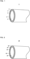
- FIG. 1 is a perspective view of an end of the steel tube of the present embodiment.
- a steel tube 1 includes a base metal 2, and an oxide coating 3 on the base metal 2.
- the steel tube 1 includes an outer surface 4 and an inner surface 5.
- the oxide coating 3 may be formed only on the outer surface 4 of the steel tube 1, may be formed only on the inner surface 5, or may be formed on both the outer surface 4 and the inner surface 5. It is possible to remove a decarburized layer of the outer surface of a vehicle component by, for example, shotpeening. On the other hand, in some cases it is difficult to remove a decarburized layer of the inner surface of a vehicle component. Therefore, preferably, the steel tube 1 includes the oxide coating 3 on at least the inner surface 5.
- the steel tube 1 of the present embodiment has the following characteristics.
- the chemical composition of the base metal 2 consists of, in mass%, C: 0.23 to 0.50%, Si: 0.01 to 0.50%, Mn: 0.50 to 2.50%, P: 0.050% or less, S: 0.0100% or less, N: 0.0100% or less, O: 0.0100% or less, sol.
- the microstructure of the base metal 2 consists of, by area fraction, ferrite in an amount of 20% to 60% and pearlite in an amount of 40% to 80%.
- the oxide coating 3 is formed which, when the sum of peak intensities in X-ray diffraction of Fe 3 O 4 , Fe 2 O 3 , and FeO is taken as 100%, is composed of, in terms of the peak intensity proportions in the X-ray diffraction, Fe 3 O 4 in an amount of 70% or more, Fe 2 O 3 in an amount of 20% or more, and FeO in an amount of 10% or less, with the balance being impurities.
- the thickness of the oxide coating 3 is 0.80 to 2.50 ⁇ m.
- the standard deviation of the thickness of the oxide coating 3 is 0.90 ⁇ m or less.
- the chemical composition of the base metal 2 of the steel tube 1 of the present embodiment contains the following elements.
- Carbon (C) increases the hardenability of the steel.
- C dissolves in the steel.
- C increases the strength of the steel.
- the content of C is less than 0.23%, the aforementioned advantageous effect will not be sufficiently obtained even if the contents of other elements are within the range of the present embodiment.
- the content of C is more than 0.50%, the hot workability of the steel will decrease even if the contents of other elements are within the range of the present embodiment.
- the content of C is more than 0.50%, furthermore, the toughness of the vehicle component after quenching will decrease even if the contents of other elements are within the range of the present embodiment. Therefore, the content of C is to be 0.23 to 0.50%.
- the lower limit of the content of C is preferably 0.25%, more preferably is 0.27%, further preferably is 0.30%, further preferably is 0.33%, further preferably is 0.35%, further preferably is 0.38%, and further preferably is 0.40%.
- Si deoxidizes the steel. Si also dissolves in the steel and thereby increases the strength of the steel. If the content of Si is less than 0.01%, the aforementioned advantageous effects will not be sufficiently obtained even if the contents of other elements are within the range of the present embodiment. On the other hand, if the content of Si is more than 0.50%, the ductility and toughness of the steel tube 1 will decrease even if the contents of other elements are within the range of the present embodiment. Therefore, the content of Si is to be 0.01 to 0.50%.
- the lower limit of the content of Si is preferably 0.05%, more preferably is 0.10%, further preferably is 0.15%, further preferably is 0.20%, and further preferably is 0.25%.
- the upper limit of the content of Si is preferably 0.45%, more preferably is 0.40%, further preferably is 0.35%, and further preferably is 0.30%.
- the lower limit of the content of Mn is preferably 0.60%, more preferably is 0.70%, further preferably is 0.75%, further preferably is 0.80%, further preferably is 0.90%, further preferably is 1.00%, and further preferably is 1.10%.
- the upper limit of the content of Mn is preferably 2.40%, more preferably is 2.30%, further preferably is 2.20%, further preferably is 2.10%, further preferably is 2.00%, further preferably is 1.90%, further preferably is 1.80%, further preferably is 1.70%, further preferably is 1.60%, and further preferably is 1.50%.
- Phosphorus (P) is an impurity. Therefore, the content of P is more than 0%. If the content of P is more than 0.050%, even if the contents of other elements are within the range of the present embodiment, P will segregate to grain boundaries, and will thereby cause the ductility of the steel to decrease. Therefore, the content of P is to be 0.050% or less.
- the content of P is preferably as low as possible. However, extremely reducing the content of P will greatly increase the production cost. Therefore, when taking industrial production into consideration, the lower limit of the content of P is preferably 0.001%, more preferably is 0.002%, further preferably is 0.003%, and further preferably is 0.005%.
- the upper limit of the content of P is preferably 0.040%, more preferably is 0.030%, further preferably is 0.020%, and further preferably is 0.010%.
- S Sulfur
- S is an impurity. Therefore, the content of S is more than 0%. If the content of S is more than 0.0100%, the hot workability, toughness, and fatigue strength of the steel will decrease even if the contents of other elements are within the range of the present embodiment. Therefore, the content of S is to be 0.0100% or less.
- the content of S is preferably as low as possible. However, extremely reducing the content of S will greatly increase the production cost. Therefore, when taking industrial production into consideration, the lower limit of the content of S is preferably 0.0001%, more preferably is 0.0002%, further preferably is 0.0003%, and further preferably is 0.0005%.
- the upper limit of the content of S is preferably 0.0080%, more preferably is 0.0070%, further preferably is 0.0060%, further preferably is 0.0050%, and further preferably is 0.0040%.
- N Nitrogen
- N is an impurity. Therefore, the content of N is more than 0%. If the content of N is more than 0.0100%, the toughness of the steel will decrease even if the contents of other elements are within the range of the present embodiment. Therefore, the content of N is to be 0.0100% or less. On the other hand, N forms nitrides and/or carbo-nitrides, thereby increasing the strength of the steel.
- a preferable lower limit of the content of N is 0.0001%, more preferably is 0.0002%, further preferably is 0.0003%, further preferably is 0.0005%, further preferably is 0.0010%, further preferably is 0.0020%, and further preferably is 0.0030%.
- the upper limit of the content of N is preferably 0.0080%, more preferably is 0.0070%, further preferably is 0.0060%, further preferably is 0.0050%, and further preferably is 0.0040%.
- Oxygen (O) is an impurity. Therefore, the content of O is more than 0%. If the content of O is more than 0.0100%, the toughness of the steel will decrease even if the contents of other elements are within the range of the present embodiment. Therefore, the content of O is to be 0.0100% or less.
- the content of O is preferably as low as possible. However, extremely reducing the content of O will greatly increase the production cost. Therefore, when taking industrial production into consideration, a preferable lower limit of the content of O is 0.0001%, more preferably is 0.0002%, further preferably is 0.0003%, and further preferably is 0.0005%.
- the upper limit of the content of O is preferably 0.0080%, more preferably is 0.0070%, further preferably is 0.0060%, further preferably is 0.0050%, further preferably is 0.0040%, and further preferably is 0.0030%.
- the balance of the chemical composition of the steel tube 1 of the present embodiment is Fe and impurities.
- impurities with respect to the chemical composition means substances which are mixed in from ore and scrap as the raw material or from the production environment or the like when industrially producing the steel tube 1, and which are not intentionally contained but are permitted within a range that does not adversely affect the steel tube 1 of the present embodiment.
- the chemical composition of the base metal 2 of the steel tube 1 of the present embodiment may further contain, in lieu of a part of Fe, one or more elements selected from the group consisting of:
- the chemical composition of the base metal 2 of the steel tube 1 according to the present embodiment may further contain Al in lieu of a part of Fe.
- Aluminum (Al) is an optional element, and does not have to be contained. That is, the content of Al may be 0%. When Al is contained, that is, when the content of Al is more than 0%, Al deoxidizes the steel. In addition, Al combines with nitrogen (N) to form AlN. The AlN suppresses coarsening of grains during quenching. If even a small amount of Al is contained, the aforementioned advantageous effects will be obtained to a certain extent. On the other hand, if the content of Al is more than 0.080%, even if the contents of other elements are within the range of the present embodiment, Al will combine with oxygen (O) and an excessive amount of inclusions will be formed. This will cause the fatigue strength of the vehicle component to decrease. Therefore, the content of Al is to be 0 to 0.080%.
- the lower limit of the content of Al is preferably more than 0%, more preferably is 0.001%, further preferably is 0.005%, further preferably is 0.010%, and further preferably is 0.015%.
- the upper limit of the content of Al is preferably 0.070%, more preferably is 0.060%, further preferably is 0.050%, further preferably is 0.040%, and further preferably is 0.030%.
- the chemical composition of the base metal 2 of the steel tube 1 according to the present embodiment may further contain one or more elements selected from a group consisting of Cr, Mo, Ni, and Cu in lieu of a part of Fe.
- Each of these elements is an optional element, and does not have to be contained. When contained, each of these elements increases the strength of the steel.
- Chromium (Cr) is an optional element, and does not have to be contained. That is, the content of Cr may be 0%. When Cr is contained, that is, when the content of Cr is more than 0%, Cr increases the strength of the steel. If even a small amount of Cr is contained, the aforementioned advantageous effect will be obtained to a certain extent. On the other hand, if the content of Cr is more than 1.50%, the ductility of the steel will decrease even if the contents of other elements are within the range of the present embodiment. Therefore, the content of Cr is to be 0 to 1.50%.
- the lower limit of the content of Cr is preferably 0.01%, more preferably is 0.05%, further preferably is 0.10%, further preferably is 0.20%, and further preferably is 0.30%.
- the upper limit of the content of Cr is preferably 1.20%, more preferably is 1.00%, further preferably is 0.80%, further preferably is 0.60%, and further preferably is 0.40%.
- Molybdenum (Mo) is an optional element, and does not have to be contained. That is, the content of Mo may be 0%. When Mo is contained, that is, when the content of Mo is more than 0%, Mo increases the strength of the steel. If even a small amount of Mo is contained, the aforementioned advantageous effect will be obtained to a certain extent. On the other hand, if the content of Mo is more than 1.00%, the ductility of the steel will decrease even if the contents of other elements are within the range of the present embodiment. Therefore, the content of Mo is to be 0 to 1.00%.
- the lower limit of the content of Mo is preferably 0.01%, more preferably is 0.02%, further preferably is 0.03%, further preferably is 0.04%, and further preferably is 0.05%.
- the upper limit of the content of Mo is preferably 0.80%, more preferably is 0.60%, further preferably is 0.40%, further preferably is 0.20%, and further preferably is 0.10%.
- the lower limit of the content of Ni is preferably 0.01%, more preferably is 0.02%, further preferably is 0.05%, further preferably is 0.10%, and further preferably is 0.15%.
- the upper limit of the content of Ni is preferably 0.80%, more preferably is 0.60%, further preferably is 0.40%, and further preferably is 0.20%.
- Copper (Cu) is an optional element, and does not have to be contained. That is, the content of Cu may be 0%. When Cu is contained, that is, when the content of Cu is more than 0%, Cu increases the strength of the steel. If even a small amount of Cu is contained, the aforementioned advantageous effect will be obtained to a certain extent. On the other hand, if the content of Cu is more than 1.00%, the ductility of the steel will decrease even if the contents of other elements are within the range of the present embodiment. Therefore, the content of Cu is to be 0 to 1.00%.
- the lower limit of the content of Cu is preferably 0.01%, more preferably is 0.02%, further preferably is 0.03%, further preferably is 0.04%, and further preferably is 0.05%.
- the upper limit of the content of Cu is preferably 0.80%, more preferably is 0.60%, further preferably is 0.40%, and further preferably is 0.20%.
- the chemical composition of the base metal 2 of the steel tube 1 according to the present embodiment may further contain one or more elements selected from a group consisting of Ti, Nb, and V in lieu of a part of Fe.
- Each of these elements is an optional element, and does not have to be contained. When contained, each of these elements increases the strength and workability of the steel.
- Titanium (Ti) is an optional element, and does not have to be contained. That is, the content of Ti may be 0%. When Ti is contained, that is, when the content of Ti is more than 0%, Ti forms carbides, nitrides, and/or carbo-nitrides. By this means, Ti increases the strength and workability of the steel. If even a small amount of Ti is contained, the aforementioned advantageous effects will be obtained to a certain extent. On the other hand, if the content of Ti is more than 0.100%, the ductility of the steel will decrease even if the contents of other elements are within the range of the present embodiment. Therefore, the content of Ti is to be 0 to 0.100%.
- the lower limit of the content of Ti is preferably 0.001%, more preferably is 0.005%, further preferably is 0.010%, further preferably is 0.020%, and further preferably is 0.030%.
- the upper limit of the content of Ti is preferably 0.090%, more preferably is 0.080%, further preferably is 0.070%, and further preferably is 0.060%.
- Niobium (Nb) is an optional element, and does not have to be contained. That is, the content of Nb may be 0%. When Nb is contained, that is, when the content of Nb is more than 0%, Nb forms carbides, nitrides, and/or carbo-nitrides. By this means, Nb increases the strength and workability of the steel. If even a small amount of Nb is contained, the aforementioned advantageous effects will be obtained to a certain extent. On the other hand, if the content of Nb is more than 0.100%, the ductility of the steel will decrease even if the contents of other elements are within the range of the present embodiment. Therefore, the content of Nb is to be 0 to 0.100%.
- the lower limit of the content of Nb is preferably 0.001%, more preferably is 0.002%, further preferably is 0.005%, further preferably is 0.010%, and further preferably is 0.015%.
- the upper limit of the content of Nb is preferably 0.090%, more preferably is 0.070%, further preferably is 0.050%, further preferably is 0.030%, and further preferably is 0.020%.
- Vanadium (V) is an optional element, and does not have to be contained. That is, the content of V may be 0%. When V is contained, that is, when the content of V is more than 0%, V forms carbides, nitrides, and/or carbo-nitrides. By this means, V increases the strength and workability of the steel. If even a small amount of V is contained, the aforementioned advantageous effects will be obtained to a certain extent. On the other hand, if the content of V is more than 0.100%, the ductility of the steel will decrease even if the contents of other elements are within the range of the present embodiment. Therefore, the content of V is to be 0 to 0.100%.
- the lower limit of the content of V is preferably 0.001%, more preferably is 0.005%, further preferably is 0.010%, further preferably is 0.015%, and further preferably is 0.020%.
- the upper limit of the content of V is preferably 0.090%, more preferably is 0.080%, further preferably is 0.070%, further preferably is 0.060%, further preferably is 0.050%, and further preferably is 0.040%.
- Boron (B) is an optional element, and does not have to be contained. That is, the content of B may be 0%. When B is contained, that is, when the content of B is more than 0%, B increases the hardenability of the steel. If even a small amount of B is contained, the aforementioned advantageous effect will be obtained to a certain extent. On the other hand, if the content of B is more than 0.0050%, even if the contents of other elements are within the range of the present embodiment, the steel will easily become brittle. Therefore, the content of B is to be 0 to 0.0050%.
- the lower limit of the content of B is preferably 0.0001%, more preferably is 0.0002%, further preferably is 0.0003%, further preferably is 0.0005%, and further preferably is 0.0010%.
- the upper limit of the content of B is preferably 0.0040%, more preferably is 0.0030%, and further preferably is 0.0020%.
- the chemical composition of the base metal 2 of the steel tube 1 according to the present embodiment may further contain Ca in lieu of a part of Fe.
- Calcium (Ca) is an optional element, and does not have to be contained. That is, the content of Ca may be 0%. When Ca is contained, that is, when the content of Ca is more than 0%, Ca increases the hot workability of the steel. If even a small amount of Ca is contained, the aforementioned advantageous effect will be obtained to a certain extent. On the other hand, if the content of Ca is more than 0.0050%, the toughness of the steel will decrease even if the contents of other elements are within the range of the present embodiment. Therefore, the content of Ca is to be 0 to 0.0050%.
- the upper limit of the content of Ca is preferably 0.0040%, more preferably is 0.0030%, and further preferably is 0.0025%.
- the chemical composition of the base metal 2 of the steel tube 1 of the present embodiment can be measured by a well-known composition analysis method.
- the steel tube 1 is cut to a length of 10 cm in the axial direction of the steel tube 1.
- the oxide coating 3 on the outer surface 4 and the inner surface 5 of the cut steel tube 1 is then removed by cutting.
- the steel tube 1 from which the oxide coating 3 has been removed is finely pulverized and dissolved in acid to obtain a liquid solution.
- the liquid solution is subjected to ICP-AES (Inductively Coupled Plasma Atomic Emission Spectrometry) to perform elementary analysis of the chemical composition.
- the content of C and the content of S are determined by a well-known high-frequency combustion method (combustion-infrared absorption method).
- the content of N is determined using a well-known inert gas fusion-thermal conductivity method.
- the content of O is determined using a well-known inert gas fusion-nondispersive infrared absorption
- a numerical value up to the least significant digit of the content of each element defined in the present embodiment that is obtained by rounding off a fraction of the measured numerical value based on the significant figures defined in the present embodiment is taken as the content of the relevant element.
- the content of C in the steel tube 1 of the present embodiment is defined as a numerical value up to the hundredths place. Therefore, a numerical value up to the hundredths place that is obtained by rounding off the thousandths place of the measured numerical value is taken as the content of C.
- a value obtained by rounding off a fraction of the numerical value of the measured value up to the least significant digit defined in the present embodiment is taken as the content of the relevant element.
- rounding off means rounding down if the fraction is less than 5, and rounding up if the fraction is 5 or more.
- the base metal 2 of the steel tube 1 of the present embodiment has a microstructure composed of, by area fraction, ferrite in an amount of 20% to 60% and pearlite in an amount of 40% to 80%.
- a vehicle component can be produced by, for example, subjecting the steel tube 1 to cold bending and thereafter performing quenching and tempering. Therefore, the steel tube 1 is required to have excellent workability.
- the microstructure of the base metal 2 is composed of, by area fraction, ferrite in an amount of 20% to 60% and pearlite in an amount of 40% to 80%, the steel tube 1 has excellent workability.
- the lower limit of the area fraction of ferrite is preferably 25%, more preferably is 30%, further preferably is 35%, and further preferably is 40%.
- the upper limit of the area fraction of ferrite is preferably 55%, more preferably is 50%, and further preferably is 45%.
- the lower limit of the area fraction of pearlite is preferably 45%, more preferably is 50%, and further preferably is 55%.
- the upper limit of the area fraction of pearlite is preferably 75%, more preferably is 70%, further preferably is 65%, and further preferably is 60%.
- the area fractions of ferrite and pearlite in the base metal 2 of the steel tube 1 are determined by the following method.
- a test specimen which includes a central portion of the wall thickness of a cross section perpendicular to the axial direction of the steel tube 1 and which has a length of 10 cm in the axial direction of the steel tube 1 is taken from each of arbitrary three locations in the steel tube 1. In other words, three test specimens are taken.
- a surface corresponding to a cross section perpendicular to the axial direction of the steel tube 1 is adopted as an observation surface.
- the observation surface of each test specimen is mirror-polished.
- the mirror-polished observation surface is subjected to etching using a 3% nitric acid-alcohol solution (nital etching reagent).
- a 3% nitric acid-alcohol solution nital etching reagent
- the central portion of the wall thickness of the steel tube 1 is set as an observation visual field.
- the size of the observation visual field is set to 200 ⁇ m ⁇ 200 ⁇ m.
- the observation visual field is observed with an optical microscope at a magnification of 500 ⁇ .
- the respective structures such as pearlite and ferrite can be easily distinguished by contrast.
- ferrite is observed as a white region.
- Pearlite is observed as a region having a lamellar structure that has a lower brightness than ferrite.
- Each structure in the observation visual field is identified.
- the area fraction (%) of ferrite is determined based on the area of ferrite in the observation visual field and the total area of the observation visual field.
- the area fraction (%) of pearlite is determined based on the area of pearlite in the observation visual field and the total area of the observation visual field.
- the arithmetic average values of the values obtained for ferrite and pearlite, respectively, in the three test specimens are defined as the area fraction of ferrite and the area fraction of pearlite, respectively.
- the steel tube 1 of the present embodiment includes the oxide coating 3 on the base metal 2.
- the oxide coating 3 is composed of, in terms of the peak intensity proportions in the X-ray diffraction, Fe 3 O 4 in an amount of 70% or more, Fe 2 O 3 in an amount of 20% or more, and FeO in an amount of 10% or less, with the balance being impurities.
- the oxide coating 3 having the composition described above is formed on the steel tube 1 before quenching. By this means, the fatigue strength of the vehicle component increases.
- the lower limit of the peak intensity proportion of Fe 3 O 4 is preferably 72%, more preferably is 74%, and further preferably is 75%.
- the upper limit of the peak intensity proportion of Fe 3 O 4 is, for example, 80%.
- the upper limit of the peak intensity proportion of Fe 3 O 4 is preferably 78%, more preferably is 76%, and further preferably is 75%.
- the composition of the oxide coating 3 of the steel tube 1 is determined by the following method.
- the surface of the oxide coating 3 is subjected to X-ray diffraction measurement to obtain an X-ray diffraction profile. Measurement is performed at arbitrary three locations on the surface of the oxide coating 3.
- the measurement conditions for the X-ray diffraction measurement are as follows.
- the peak intensities in the X-ray diffraction of Fe 3 O 4 , Fe 2 O 3 , and FeO are determined from the obtained X-ray diffraction profile.
- the sum of the peak intensities in the X-ray diffraction of Fe 3 O 4 , Fe 2 O 3 , and FeO is taken as 100%.
- the peak intensity proportions of Fe 3 O 4 , Fe 2 O 3 , and FeO are determined based on the sum of the peak intensities, and the peak intensities in the X-ray diffraction of Fe 3 O 4 , Fe 2 O 3 , and FeO.
- the arithmetic average value of the numerical values measured at the three locations is taken as the peak intensity proportion. Note that, the intensity proportion of each peak does not necessarily match the area ratio or the mass percent determined by quantitative analysis of the respective peaks.
- the thickness of the oxide coating 3 is less than 0.80 ⁇ m, an effect that suppresses contact between the surfaces 4 and 5 of the steel tube 1 and oxygen will not be obtained.
- the thickness of the oxide coating 3 is more than 2.50 ⁇ m, the adhesion of the oxide coating 3 will decrease and the oxide coating 3 will peel off from the surfaces 4 and 5 of the steel tube 1. Therefore, the thickness of the oxide coating 3 is to be 0.80 to 2.50 ⁇ m.
- the lower limit of the thickness of the oxide coating 3 is preferably 0.84 ⁇ m, more preferably is 0.88 ⁇ m, further preferably is 1.00 ⁇ m, and further preferably is 1.20 ⁇ m.
- the upper limit of the thickness of the oxide coating 3 is preferably 2.40 ⁇ m, more preferably is 2.30 ⁇ m, further preferably is 2.20 ⁇ m, further preferably is 2.00 ⁇ m, and further preferably is 1.80 ⁇ m.
- the thickness of the oxide coating 3 of the steel tube 1 is determined by the following method.
- the steel tube 1 is cut perpendicularly to the axial direction to obtain test specimens.
- Three test specimens are taken at a pitch of 100 mm in the axial direction of the steel tube 1.
- a cut surface which is perpendicular to the axial direction of the steel tube 1 is adopted as the observation surface.
- Each test specimen is embedded in resin in a manner so that the observation surface can be observed. After the test specimen is embedded in resin, the observation surface is polished.
- a scanning electron microscope (SEM) - energy dispersive X-ray spectroscope (EDS) is used to generate a secondary electron image of an observation visual field including the oxide coating 3 on the observation surface after polishing.
- the size of the observation visual field is set to 50 ⁇ m ⁇ 40 ⁇ m.
- the observation visual field is set to an area with dimensions of 50 ⁇ m in the radial direction of the steel tube 1 and 40 ⁇ m in the direction perpendicular to the radial direction (the direction perpendicular to the radial direction corresponds to the circumferential direction, and hereunder is referred to as "C direction").
- the base metal 2 and the oxide coating 3 can be easily distinguished based on contrast.
- the base metal 2 and the oxide coating 3 may be distinguished from each other by performing elemental mapping of oxygen (O) in the observation visual field using an EDS device attached to an SEM.
- elemental mapping of oxygen (O) by an EDS a region in which the oxygen concentration is high corresponds to the oxide coating 3 and a region in which the oxygen concentration is low corresponds to the base metal 2. Since a region in which the oxygen concentration is high and a region in which the oxygen concentration is low are clearly separated, the oxide coating 3 can be easily distinguished.
- the thickness of the identified oxide coating 3 is measured at 10 locations at a pitch of 3 ⁇ m in the C direction.
- the arithmetic average value of the values obtained for the thickness of the oxide coating 3 at the measurement locations on the three test specimens (total of 30 locations) is defined as the thickness of the oxide coating 3.
- the standard deviation of the thickness of the oxide coating 3 is more than 0.90 ⁇ m, contact between the surfaces 4 and 5 of the steel tube 1 and oxygen cannot be suppressed at a portion where the oxide coating 3 is thin. In such case, intergranular oxidation will occur locally on the surfaces 4 and 5 of the steel tube 1.
- the standard deviation of the thickness of the oxide coating 3 is to be 0.90 ⁇ m or less.
- the lower limit of the standard deviation of the thickness of the oxide coating 3 may be 0 ⁇ m.
- the lower limit of the standard deviation of the thickness of the oxide coating 3 is preferably 0.01 ⁇ m, more preferably is 0.03 ⁇ m, and further preferably is 0.05 ⁇ m.
- the upper limit of the thickness of the oxide coating 3 is preferably 0.80 ⁇ m, more preferably is 0.70 ⁇ m, further preferably is 0.60 ⁇ m, and further preferably is 0.50 ⁇ m.
- the standard deviation of the thickness of the oxide coating of the steel tube is determined by the following method.
- the thickness of the oxide coating 3 is measured by the method described above in the section [Method for measuring thickness of oxide coating of steel tube].
- the standard deviation of the thickness of the oxide coating 3 at the 30 locations is defined as the standard deviation of the thickness of the oxide coating 3.
- standard deviation refers to the "sample standard deviation” (JIS Z8101-1: 2015).
- the method for producing the steel tube 1 described hereinafter is one example for producing the steel tube 1 of the present embodiment. Accordingly, the steel tube 1 composed as described above may also be produced by a production method other than the production method described hereinafter. However, the production method described hereinafter is a preferable example of a method for producing the steel tube 1 of the present embodiment.
- One example of a method for producing the steel tube 1 of the present embodiment includes the following steps.
- a steel sheet for producing the steel tube 1 of the present embodiment is prepared.
- the steel sheet may be obtained from a third party, or may be produced.
- molten steel in which the content of each element in the chemical composition is within the range of the present embodiment is produced.
- the refining method is not particularly limited and it suffices to use a well-known method.
- the molten steel is used to produce a starting material by a well-known casting process. For example, an ingot may be produced by an ingot-making process using the molten steel. Further, a bloom may be produced by a continuous casting process using the molten steel. A starting material (ingot or bloom) is produced by the above method.
- the starting material is heated and subjected to rough rolling and finish rolling by a well-known method.
- the coiling temperature of the steel sheet is, for example, within the range of more than 600 to 700°C.
- a steel sheet having a microstructure composed of, by area fraction, ferrite in an amount of 20% to 60% and pearlite in an amount of 40% to 80% is produced by the above production process.
- Heat treatment temperature 450 to 600°C
- the produced hot-rolled steel sheet is in a state in which it has been wound into a coil.
- the steel sheet is uncoiled, and a low-temperature heat treatment is performed in a state in which the surface of the steel sheet is exposed to an air atmosphere.
- the low-temperature heat treatment conditions are as described above.
- the oxide coating 3 that is composed of, in terms of peak intensity proportions in X-ray diffraction on the surface of the steel sheet, Fe 3 O 4 in an amount of 70% or more, Fe 2 O 3 in an amount of 20% or more, and FeO in an amount of 10% or less with the balance being impurities, and that has a thickness of 0.80 to 2.50 ⁇ m, and in which the standard deviation of the thickness is 0.90 ⁇ m or less is formed by the low-temperature heat treatment.
- the aforementioned oxide coating is formed, the fatigue strength of the vehicle component increases.
- a preferable lower limit of the heat treatment temperature is more than 450°C, more preferably is 460°C, and further preferably is 470°C.
- An electric resistance welded steel tube is produced using the hot-rolled steel sheet that underwent the low-temperature heat treatment.
- a forming roll is used to form the hot-rolled steel sheet into a cylindrical hollow shell (open steel tube).
- the formed hollow shell is formed in a manner so that the width direction of the hot-rolled steel sheet is the circumferential direction of the hollow shell. Butted parts extending in the longitudinal direction of the hollow shell are subjected to electric resistance welding.
- An electric resistance welded steel tube is produced by the above tube-making step.
- the steel tube 1 of the present embodiment can be produced by the above steps.
- a method for producing the steel tube 1 of the present embodiment may also include one or more other steps.
- An example of another step is a diameter-reduction rolling step.
- diameter-reduction rolling step for example, diameter-reduction rolling may be performed according to well-known conditions.
- the steel tube 1 of the present disclosure is used as a starting material for vehicle components.
- vehicle components are, for example, a stabilizer, an inner tie rod, a drive shaft, an upper arm, and the like.
- the steel tube 1 is suitable for use in a stabilizer.
- the steel tube 1 of the present embodiment has the following characteristics.
- the chemical composition of the base metal 2 consists of, in mass%, C: 0.23 to 0.50%, Si: 0.01 to 0.50%, Mn: 0.50 to 2.50%, P: 0.050% or less, S: 0.0100% or less, N: 0.0100% or less, O: 0.0100% or less, sol.
- the thickness of the oxide coating 3 is 0.80 to 2.50 ⁇ m.
- the standard deviation of the thickness of the oxide coating 3 is 0.90 ⁇ m or less.
- the steel tube 1 of the present embodiment that has Characteristics 1 to 5 can be used to produce a vehicle component which is excellent in fatigue strength. That is, in the case of the steel tube 1 of the present embodiment, excellent fatigue strength is obtained in a vehicle component that is produced using the steel tube 1 as a starting material.
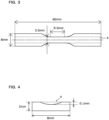
- FIG. 2 is a perspective view of an end of a vehicle component of the present embodiment.
- a vehicle component 10 includes a hollow-shell base metal 20, and an oxide coating 30 on the base metal 20.
- the vehicle component 10 includes an outer surface 40 and an inner surface 50.
- the oxide coating 30 may be formed only on the outer surface 40 of the vehicle component 10, may be formed only on the inner surface 50 of the vehicle component 10, or may be formed on both the outer surface 40 and the inner surface 50. It is possible to remove a decarburized layer of the outer surface 40 of the vehicle component 10 by, for example, shotpeening. On the other hand, in some cases it is difficult to remove a decarburized layer of the inner surface 50 of the vehicle component 10. Therefore, preferably, the vehicle component 10 includes the oxide coating 30 on at least the inner surface 50.
- the vehicle component 10 is, for example, a stabilizer, an inner tie rod, a drive shaft, an upper arm or the like.
- the vehicle component 10 of the present embodiment has the following characteristics.
- the chemical composition of the base metal 20 consists of, in mass%, C: 0.23 to 0.50%, Si: 0.01 to 0.50%, Mn: 0.50 to 2.50%, P: 0.050% or less, S: 0.0100% or less, N: 0.0100% or less, O: 0.0100% or less, sol.
- the microstructure of the base metal 20 consists of tempered martensite, and a Vickers hardness in accordance with JIS Z 2244: 2020 of the base metal 20 is 400 to 550 HV.
- the oxide coating 30 which, when a sum of the peak intensities in X-ray diffraction of Fe 3 O 4 , FeO, and Fe 2 O 3 is taken as 100%, is composed of, in terms of the peak intensity proportions in the X-ray diffraction, Fe 3 O 4 in an amount of 80% or more, FeO in an amount of 15% or less, and Fe 2 O 3 in an amount of 5% or less, with the balance being impurities, is formed on the base metal 20.
- the thickness of the oxide coating 30 is 3.50 ⁇ m or less.
- the chemical composition of the base metal 20 of the vehicle component 10 of the present embodiment contains the following elements.
- the upper limit of the content of C is preferably 0.48%, more preferably is 0.46%, further preferably is 0.44%, further preferably is 0.42%, further preferably is 0.40%, and further preferably is 0.38%.
- Si deoxidizes the steel. Si also dissolves in the steel and thereby increases the strength of the steel. If the content of Si is less than 0.01%, the aforementioned advantageous effects will not be sufficiently obtained even if the contents of other elements are within the range of the present embodiment. On the other hand, if the content of Si is more than 0.50%, the ductility and toughness of the vehicle component 10 will decrease even if the contents of other elements are within the range of the present embodiment. Therefore, the content of Si is to be 0.01 to 0.50%.
- the lower limit of the content of Si is preferably 0.05%, more preferably is 0.10%, further preferably is 0.15%, further preferably is 0.20%, and further preferably is 0.25%.
- the upper limit of the content of Si is preferably 0.45%, more preferably is 0.40%, further preferably is 0.35%, and further preferably is 0.30%.
- Manganese (Mn) increases the hardenability of the steel. Mn also dissolves in the steel. By this means, Mn increases the strength of the steel. If the content of Mn is less than 0.50%, the aforementioned advantageous effects will not be sufficiently obtained even if the contents of other elements are within the range of the present embodiment. On the other hand, if the content of Mn is more than 2.50%, the toughness and ductility of the vehicle component 10 after quenching will decrease even if the contents of other elements are within the range of the present embodiment. Therefore, the content of Mn is to be 0.50 to 2.50%.
- the lower limit of the content of Mn is preferably 0.60%, more preferably is 0.70%, further preferably is 0.75%, further preferably is 0.80%, further preferably is 0.90%, further preferably is 1.00%, and further preferably is 1.10%.
- the upper limit of the content of Mn is preferably 2.40%, more preferably is 2.30%, further preferably is 2.20%, further preferably is 2.10%, further preferably is 2.00%, further preferably is 1.90%, further preferably is 1.80%, further preferably is 1.70%, further preferably is 1.60%, and further preferably is 1.50%.
- Phosphorus (P) is an impurity. Therefore, the content of P is more than 0%. If the content of P is more than 0.050%, even if the contents of other elements are within the range of the present embodiment, P will segregate to grain boundaries, and will thereby cause the ductility of the steel to decrease. Therefore, the content of P is to be 0.050% or less.
- the content of P is preferably as low as possible. However, extremely reducing the content of P will greatly increase the production cost. Therefore, when taking industrial production into consideration, the lower limit of the content of P is preferably 0.001%, more preferably is 0.002%, further preferably is 0.003%, and further preferably is 0.005%.
- the upper limit of the content of P is preferably 0.040%, more preferably is 0.030%, further preferably is 0.020%, and further preferably is 0.010%.
- S Sulfur
- S is an impurity. Therefore, the content of S is more than 0%. If the content of S is more than 0.0100%, the hot workability, toughness, and fatigue strength of the steel will decrease even if the contents of other elements are within the range of the present embodiment. Therefore, the content of S is to be 0.0100% or less.
- the content of S is preferably as low as possible. However, extremely reducing the content of S will greatly increase the production cost. Therefore, when taking industrial production into consideration, the lower limit of the content of S is preferably 0.0001%, more preferably is 0.0002%, further preferably is 0.0003%, and further preferably is 0.0005%.
- the upper limit of the content of S is preferably 0.0080%, more preferably is 0.0070%, further preferably is 0.0060%, further preferably is 0.0050%, and further preferably is 0.0040%.
- N Nitrogen
- N is an impurity. Therefore, the content of N is more than 0%. If the content of N is more than 0.0100%, the toughness of the steel will decrease even if the contents of other elements are within the range of the present embodiment. Therefore, the content of N is to be 0.0100% or less. On the other hand, N forms nitrides and/or carbo-nitrides, thereby increasing the strength of the steel.
- a preferable lower limit of the content of N is 0.0001%, more preferably is 0.0002%, further preferably is 0.0003%, further preferably is 0.0005%, further preferably is 0.0010%, further preferably is 0.0020%, and further preferably is 0.0030%.
- the upper limit of the content of N is preferably 0.0080%, more preferably is 0.0070%, further preferably is 0.0060%, further preferably is 0.0050%, and further preferably is 0.0040%.
- Oxygen (O) is an impurity. Therefore, the content of O is more than 0%. If the content of O is more than 0.0100%, the toughness of the steel will decrease even if the contents of other elements are within the range of the present embodiment. Therefore, the content of O is to be 0.0100% or less.
- the content of O is preferably as low as possible. However, extremely reducing the content of O will greatly increase the production cost. Therefore, when taking industrial production into consideration, a preferable lower limit of the content of O is 0.0001%, more preferably is 0.0002%, further preferably is 0.0003%, and further preferably is 0.0005%.
- the upper limit of the content of O is preferably 0.0080%, more preferably is 0.0070%, further preferably is 0.0060%, further preferably is 0.0050%, further preferably is 0.0040%, and further preferably is 0.0030%.
- the balance of the chemical composition of the base metal 20 of the vehicle component 10 of the present embodiment is Fe and impurities.
- impurities with respect to the chemical composition means substances which are mixed in from ore and scrap as the raw material or from the production environment or the like when industrially producing the base metal 20 of the vehicle component 10, and which are not intentionally contained but are permitted within a range that does not adversely affect the base metal 20 of the vehicle component 10 of the present embodiment.
- the chemical composition of the base metal 20 of the vehicle component 10 of the present embodiment may further contain, in lieu of a part of Fe, one or more elements selected from the group consisting of:
- the chemical composition of the base metal 20 of the vehicle component 10 according to the present embodiment may further contain Al in lieu of a part of Fe.
- Aluminum (Al) is an optional element, and does not have to be contained. That is, the content of Al may be 0%. When Al is contained, that is, when the content of Al is more than 0%, Al deoxidizes the steel. In addition, Al combines with nitrogen (N) to form AlN. The AlN suppresses coarsening of grains during quenching. If even a small amount of Al is contained, the aforementioned advantageous effect will be obtained to a certain extent. On the other hand, if the content of Al is more than 0.080%, even if the contents of other elements are within the range of the present embodiment, Al will combine with oxygen (O) and an excessive amount of inclusions will be formed. This will cause the fatigue strength of the vehicle component 10 to decrease. Therefore, the content of Al is to be 0 to 0.080%.
- the lower limit of the content of Al is preferably more than 0%, more preferably is 0.001%, further preferably is 0.005%, further preferably is 0.010%, and further preferably is 0.015%.
- the upper limit of the content of Al is preferably 0.070%, more preferably is 0.060%, further preferably is 0.050%, further preferably is 0.040%, and further preferably is 0.030%.
- Chromium (Cr) is an optional element, and does not have to be contained. That is, the content of Cr may be 0%. When Cr is contained, that is, when the content of Cr is more than 0%, Cr increases the strength of the vehicle component 10. If even a small amount of Cr is contained, the aforementioned advantageous effect will be obtained to a certain extent. On the other hand, if the content of Cr is more than 1.50%, the ductility of the vehicle component 10 will decrease even if the contents of other elements are within the range of the present embodiment. Therefore, the content of Cr is to be 0 to 1.50%.
- the lower limit of the content of Cr is preferably 0.01%, more preferably is 0.05%, further preferably is 0.10%, further preferably is 0.20%, and further preferably is 0.30%.
- the upper limit of the content of Cr is preferably 1.20%, more preferably is 1.00%, further preferably is 0.80%, further preferably is 0.60%, and further preferably is 0.40%.
- Molybdenum (Mo) is an optional element, and does not have to be contained. That is, the content of Mo may be 0%. When Mo is contained, that is, when the content of Mo is more than 0%, Mo increases the strength of the vehicle component 10. If even a small amount of Mo is contained, the aforementioned advantageous effect will be obtained to a certain extent. On the other hand, if the content of Mo is more than 1.00%, the ductility of the vehicle component 10 will decrease even if the contents of other elements are within the range of the present embodiment. Therefore, the content of Mo is to be 0 to 1.00%.
- the lower limit of the content of Mo is preferably 0.01%, more preferably is 0.02%, further preferably is 0.03%, further preferably is 0.04%, and further preferably is 0.05%.
- the lower limit of the content of Ni is preferably 0.01%, more preferably is 0.02%, further preferably is 0.05%, further preferably is 0.10%, and further preferably is 0.15%.
- Copper (Cu) is an optional element, and does not have to be contained. That is, the content of Cu may be 0%. When Cu is contained, that is, when the content of Cu is more than 0%, Cu increases the strength of the vehicle component 10. If even a small amount of Cu is contained, the aforementioned advantageous effect will be obtained to a certain extent. On the other hand, if the content of Cu is more than 1.00%, the ductility of the vehicle component 10 will decrease even if the contents of other elements are within the range of the present embodiment. Therefore, the content of Cu is to be 0 to 1.00%.
- the lower limit of the content of Cu is preferably 0.01%, more preferably is 0.02%, further preferably is 0.03%, further preferably is 0.04%, and further preferably is 0.05%.
- the upper limit of the content of Cu is preferably 0.80%, more preferably is 0.60%, further preferably is 0.40%, and further preferably is 0.20%.
- Ti increases the strength and workability of the vehicle component 10. If even a small amount of Ti is contained, the aforementioned advantageous effect will be obtained to a certain extent. On the other hand, if the content of Ti is more than 0.100%, the ductility of the vehicle component 10 will decrease even if the contents of other elements are within the range of the present embodiment. Therefore, the content of Ti is to be 0 to 0.100%.
- the lower limit of the content of Ti is preferably 0.001%, more preferably is 0.005%, further preferably is 0.010%, further preferably is 0.020%, and further preferably is 0.030%.
- the upper limit of the content of Ti is preferably 0.090%, more preferably is 0.080%, further preferably is 0.070%, and further preferably is 0.060%.
- Niobium (Nb) is an optional element, and does not have to be contained. That is, the content of Nb may be 0%. When Nb is contained, that is, when the content of Nb is more than 0%, Nb forms carbides, nitrides, and/or carbo-nitrides. By this means, Nb increases the strength and workability of the vehicle component 10. If even a small amount of Nb is contained, the aforementioned advantageous effect will be obtained to a certain extent. On the other hand, if the content of Nb is more than 0.100%, the ductility of the vehicle component 10 will decrease even if the contents of other elements are within the range of the present embodiment. Therefore, the content of Nb is to be 0 to 0.100%.
- the lower limit of the content of Nb is preferably 0.001%, more preferably is 0.002%, further preferably is 0.005%, further preferably is 0.010%, and further preferably is 0.015%.
- the upper limit of the content of Nb is preferably 0.090%, more preferably is 0.070%, further preferably is 0.050%, further preferably is 0.030%, and further preferably is 0.020%.
- Vanadium (V) is an optional element, and does not have to be contained. That is, the content of V may be 0%. When V is contained, that is, when the content of V is more than 0%, V forms carbides, nitrides, and/or carbo-nitrides. By this means, V increases the strength and workability of the vehicle component 10.
- V is more than 0.100%, the ductility of the vehicle component 10 will decrease even if the contents of other elements are within the range of the present embodiment. Therefore, the content of V is to be 0 to 0.100%.
- the lower limit of the content of V is preferably 0.001%, more preferably is 0.005%, further preferably is 0.010%, further preferably is 0.015%, and further preferably is 0.020%.
- the upper limit of the content of V is preferably 0.090%, more preferably is 0.080%, further preferably is 0.070%, further preferably is 0.060%, further preferably is 0.050%, and further preferably is 0.040%.
- Boron (B) is an optional element, and does not have to be contained. That is, the content of B may be 0%. When B is contained, that is, when the content of B is more than 0%, B increases the hardenability of the steel. If even a small amount ofB is contained, the aforementioned advantageous effect will be obtained to a certain extent. On the other hand, if the content of B is more than 0.0050%, even if the contents of other elements are within the range of the present embodiment, the vehicle component 10 will easily become brittle. Therefore, the content of B is to be 0 to 0.0050%.
- the lower limit of the content of B is preferably 0.0001%, more preferably is 0.0002%, further preferably is 0.0003%, further preferably is 0.0005%, and further preferably is 0.0010%.
- the upper limit of the content of B is preferably 0.0040%, more preferably is 0.0030%, and further preferably is 0.0020%.
- the chemical composition of the base metal 20 of the vehicle component 10 according to the present embodiment may further contain Ca in lieu of a part of Fe.
- Calcium (Ca) is an optional element, and does not have to be contained. That is, the content of Ca may be 0%. When Ca is contained, that is, when the content of Ca is more than 0%, Ca increases the hot workability of the steel. If even a small amount of Ca is contained, the aforementioned advantageous effect will be obtained to a certain extent. On the other hand, if the content of Ca is more than 0.0050%, the toughness of the vehicle component 10 will decrease even if the contents of other elements are within the range of the present embodiment. Therefore, the content of Ca is to be 0 to 0.0050%.
- the lower limit of the content of Ca is preferably 0.0001%, more preferably is 0.0002%, further preferably is 0.0003%, further preferably is 0.0005%, further preferably is 0.0010%, and further preferably is 0.0015%.
- the upper limit of the content of Ca is preferably 0.0040%, more preferably is 0.0030%, and further preferably is 0.0025%.
- the chemical composition of the base metal 20 of the vehicle component 10 of the present embodiment is determined by the same method as the method used to determine the chemical composition of the base metal 2 of the steel tube 1.
- the vehicle component 10 is cut to a length of 10 cm in the axial direction of the vehicle component 10.
- the oxide coating 30 on the outer surface 40 and the inner surface 50 of the cut vehicle component 10 is then removed by cutting.
- the vehicle component 10 from which the oxide coating 30 has been removed is finely pulverized and dissolved in acid to obtain a liquid solution.
- the liquid solution is subjected to ICP-AES to perform elementary analysis of the chemical composition.
- the content of C and the content of S are determined by a well-known high-frequency combustion method (combustion-infrared absorption method).
- the content of N is determined using a well-known inert gas fusion-thermal conductivity method.
- the content of O is determined using a well-known inert gas fusion-nondispersive infrared absorption method.
- a numerical value up to the least significant digit of the content of each element defined in the present embodiment that is obtained by rounding off a fraction of the measured numerical value based on the significant figures defined in the present embodiment is taken as the content of the relevant element.
- the base metal 20 of the vehicle component 10 of the present embodiment has a microstructure composed of tempered martensite, and the Vickers hardness in accordance with JIS Z 2244: 2020 of the base metal 20 is 400 to 550 HV.
- the microstructure of the base metal 20 of the vehicle component 10 of the present embodiment is composed of tempered martensite.
- the area fraction of any phase other than tempered martensite is negligibly small.
- the area fraction of tempered martensite of the base metal 20 of the vehicle component 10 is determined by the following method.
- a test specimen which includes a central portion of the wall thickness of a cross section perpendicular to the longitudinal direction of the vehicle component 10 and which has a length of 10 cm in the longitudinal direction of the vehicle component 10 is taken from arbitrary three locations of the vehicle component 10. In other words, three test specimens are taken.
- a surface corresponding to a cross section perpendicular to the longitudinal direction of the vehicle component 10 is adopted as an observation surface.
- the observation surface of each test specimen is mirror-polished.
- the mirror-polished observation surface is subjected to etching using a 3% nitric acid-alcohol solution (nital etching reagent).
- the central portion of the wall thickness of the vehicle component 10 is set as an observation visual field.
- the size of the observation visual field is set to 200 ⁇ m ⁇ 200 ⁇ m.
- the observation visual field is observed with an optical microscope at a magnification of 500x.
- Tempered martensite is observed as a fine structure which is gray and has low brightness. Ferrite is observed as a white region that has a higher brightness than tempered martensite and pearlite. Pearlite is observed as a phase having a lamellar structure that has a lower brightness than ferrite.
- the area fraction (%) of tempered martensite is determined based on the area of tempered martensite in the observation visual field and the total area of the observation visual field. The arithmetic average value of the values obtained for the three test specimens is defined as the area fraction of tempered martensite.
- the Vickers hardness in accordance with JIS Z 2244: 2020 is 400 to 550 HV.
- a preferable lower limit of the Vickers hardness is 405 HV, more preferably is 410 HV, further preferably is 415 HV, and further preferably is 420 HV.
- a preferable upper limit of the Vickers hardness is 545 HV, more preferably is 540 HV, further preferably is 535 HV, further preferably is 530 HV, and further preferably is 525 HV.
- the Vickers hardness of the base metal 20 of the vehicle component 10 of the present embodiment is measured by the following method.
- a test specimen in which a longitudinal section parallel to the longitudinal direction of the vehicle component 10 is adopted as a measurement surface is taken.
- the measurement surface of the test specimen is polished.
- the Vickers hardness (HV) in accordance with JIS Z 2244: 2020 is measured at arbitrary three locations in the base metal 20 which are at positions at a depth of 20 ⁇ m on the inner part of the base metal 20 from the boundary (interface) between the oxide coating 30 and the base metal 20.
- the test force during measurement is to be 0.098 N.
- the arithmetic average value of the obtained values is defined as the Vickers hardness (HV).
- the determination to distinguish between the oxide coating 30 and the base metal 20 is performed based on the difference in brightness using a microscope.
- the vehicle component 10 of the present embodiment includes the oxide coating 30 on the base metal 20.
- the oxide coating 30 is composed of, when a sum of the peak intensities in X-ray diffraction of Fe 3 O 4 , FeO, and Fe 2 O 3 is taken as 100%, in terms of the peak intensity proportions in the X-ray diffraction, Fe 3 O 4 in an amount of 80% or more, FeO in an amount of 15% or less, and Fe 2 O 3 in an amount of 5% or less, with the balance being impurities.
- the lower limit of the peak intensity proportion of Fe 3 O 4 is preferably 81%, more preferably is 85%, and further preferably is 90%.
- the upper limit of the peak intensity proportion of Fe 3 O 4 may be 100%.
- the upper limit of the peak intensity proportion of Fe 3 O 4 is preferably 99%, more preferably is 98%, further preferably is 97%, and further preferably is 96%.
- the lower limit of the peak intensity proportion of FeO may be 0%.
- the lower limit of the peak intensity proportion of FeO is preferably 1%, more preferably is 2%, and further preferably is 3%.
- the upper limit of the peak intensity proportion of FeO is preferably 14%, more preferably is 13%, further preferably is 12%, and further preferably is 11%.
- the lower limit of the peak intensity proportion of Fe 2 O 3 may be 0%.
- the lower limit of the peak intensity proportion of Fe 2 O 3 is preferably 0.1%, and more preferably is 0.2%.
- the upper limit of the peak intensity proportion of Fe 2 O 3 is preferably 4%, and more preferably is 3%.
- the composition of the oxide coating 30 of the vehicle component 10 is determined by the following method.
- the surface of the oxide coating 30 is subjected to X-ray diffraction measurement to obtain an X-ray diffraction profile. Measurement is performed at arbitrary three locations on the surface of the oxide coating 30.
- the measurement conditions for the X-ray diffraction measurement are the same as the measurement conditions described above in the section [Method for measuring composition of oxide coating of steel tube].
- the peak intensities in the X-ray diffraction of Fe 3 O 4 , FeO, and Fe 2 O 3 are determined from the obtained X-ray diffraction profile.
- the sum of the peak intensities in the X-ray diffraction of Fe 3 O 4 , FeO, and Fe 2 O 3 is taken as 100%.
- the peak intensity proportions of Fe 3 O 4 , FeO, and Fe 2 O 3 are determined based on the sum of the peak intensities, and the peak intensities in the X-ray diffraction of Fe 3 O 4 , FeO, and Fe 2 O 3 .
- the arithmetic average value of the numerical values measured at the three locations is taken as the peak intensity proportion. Note that, the intensity proportion of each peak does not necessarily match the area ratio or the mass percent determined by quantitative analysis of the respective peaks.
- the thickness of the oxide coating 30 is more than 3.50 ⁇ m, the adhesion of the oxide coating 30 will decrease. Therefore, the thickness of the oxide coating 30 is to be 3.50 ⁇ m or less.
- the lower limit of the thickness of the oxide coating 30 is, for example, 0.01 ⁇ m.
- the lower limit of the thickness of the oxide coating 30 is preferably 0.50 ⁇ m, more preferably is 1.00 ⁇ m, further preferably is 1.50 ⁇ m, and further preferably is 2.00 ⁇ m.
- the upper limit of the thickness of the oxide coating 30 is preferably 3.40 ⁇ m, more preferably is 3.20 ⁇ m, further preferably is 3.00 ⁇ m, further preferably is 2.90 ⁇ m, further preferably is 2.80 ⁇ m, and further preferably is 2.50 ⁇ m.
- the thickness of the oxide coating 30 of the vehicle component 10 is determined by the following method.
- the vehicle component 10 is cut perpendicularly to the longitudinal direction to obtain test specimens.
- Three test specimens are taken at a pitch of 100 mm in the longitudinal direction of the vehicle component 10.
- the cut surface is adopted as the observation surface.
- Each test specimen is embedded in resin in a manner so that the observation surface can be observed.
- the observation surface is polished.
- An SEM-EDS is used to generate a secondary electron image of an observation visual field including the oxide coating 30 on the observation surface after polishing.
- the size of the observation visual field is set to 50 ⁇ m ⁇ 40 ⁇ m.
- the observation visual field is set to an area with dimensions of 50 ⁇ m in the radial direction of the vehicle component 10 and 40 ⁇ m in the direction perpendicular to the radial direction (the direction perpendicular to the radial direction corresponds to the circumferential direction, and hereunder is referred to as the "C direction").
- the base metal 20 and the oxide coating 30 can be easily distinguished based on contrast.
- the base metal 20 and the oxide coating 30 may be distinguished from each other by performing elemental mapping of oxygen (O) in the observation visual field using an EDS device attached to an SEM.
- elemental mapping of oxygen (O) by an EDS a region in which the oxygen concentration is high corresponds to the oxide coating 30 and a region in which the oxygen concentration is low corresponds to the base metal 20. Since a region in which the oxygen concentration is high and a region in which the oxygen concentration is low are clearly separated, the oxide coating 30 can be easily distinguished.
- the oxide coating 30 since the oxide coating 30 is thicker than the oxide coating 3, in some cases the oxide coating 30 may peel off during polishing. In such case, there may be times where the oxide coating cannot be identified by elemental mapping of oxygen (O) using an SEM-EDS. However, in such a case, a gap between the resin and the base metal 20 after the oxide coating 30 has peeled off may be regarded as the oxide coating 30.
- O elemental mapping of oxygen
- the thickness of the identified oxide coating 30 is measured at 10 locations at a pitch of 3 ⁇ m in the C direction.
- the arithmetic average value of the values of the thickness of the oxide coating 30 obtained at the measurement locations of the three test specimens (total of 30 locations) is defined as the thickness of the oxide coating 30.
- the method for producing the vehicle component 10 described hereinafter is one example for producing the vehicle component 10 of the present embodiment. Accordingly, the vehicle component 10 composed as described above may also be produced by a production method other than the production method described hereinafter. However, the production method described hereinafter is a preferable example of a method for producing the vehicle component 10 of the present embodiment.
- One example of a method for producing the vehicle component 10 of the present embodiment includes the following steps.
- the steel tube 1 for producing the vehicle component 10 of the present embodiment is prepared.
- the steel tube 1 is cut to a predetermined length.
- the cut steel tube 1 is subjected to cold bending to be bent into a predetermined shape.
- the bent steel tube 1 is heated under the following condition, and thereafter is rapidly cooled.
- a well-known cooling method is employed as the cooling method.
- a c3 +50°C or more to 1150°C or less
- the A c3 point (°C) is defined by the following formula.
- a c3 910-203 ⁇ ( ⁇ C)-15.2 ⁇ Ni+44.7 ⁇ Si+104 ⁇ V+31.5 ⁇ Mo (A)
- the steel tube 1 after quenching is tempered under the following conditions.
- Tempering temperature 150 to 350°C
- the vehicle component 10 of the present embodiment can be produced by the above steps.
- the method for producing the vehicle component 10 of the present embodiment may also include one or more other steps.
- An example of another step is a surface treatment step.
- the surface treatment step for example, the outer surface 40 of the obtained vehicle component 10 may be subjected to shotpeening.
- the outer surface 40 of the obtained vehicle component 10 may be subjected to a dustproofing treatment.
- the vehicle component 10 of the present disclosure is suitable for use as a stabilizer. However, use of the vehicle component 10 of the present disclosure is not limited to use as a stabilizer.
- the vehicle component 10 of the present disclosure can also be used, for example, as an inner tie rod, a drive shaft, or an upper arm.
- the vehicle component 10 of the present embodiment has the following characteristics.
- the chemical composition of the base metal 20 consists of, in mass%, C: 0.23 to 0.50%, Si: 0.01 to 0.50%, Mn: 0.50 to 2.50%, P: 0.050% or less, S: 0.0100% or less, N: 0.0100% or less, O: 0.0100% or less, sol.
- the microstructure of the base metal 20 is composed of tempered martensite, and the Vickers hardness in accordance with JIS Z 2244: 2020 of the base metal 20 is 400 to 550 HV.
- the oxide coating 30 which, when a sum of the peak intensities in X-ray diffraction of Fe 3 O 4 , FeO, and Fe 2 O 3 is taken as 100%, is composed of, in terms of the peak intensity proportions in the X-ray diffraction, Fe 3 O 4 in an amount of 80% or more, FeO in an amount of 15% or less, and Fe 2 O 3 in an amount of 5% or less, with the balance being impurities, is formed on the base metal 20.
- the thickness of the oxide coating 30 is 3.50 ⁇ m or less.
- the vehicle component 10 of the present embodiment that has Characteristics 6 to 9 is excellent in fatigue strength.
- the advantageous effects of the steel tube 1 and the vehicle component 10 of the present embodiment are described more specifically hereunder by way of examples.
- the conditions adopted in the following examples are one example of conditions adopted for confirming the feasibility and advantageous effects of the steel tube 1 and the vehicle component 10 of the present embodiment. Accordingly, the steel tube 1 and the vehicle component 10 of the present embodiment are not limited to this one example of conditions.
- Sample materials (steel sheets simulating steel tubes) having the chemical compositions shown in Table 1A and Table 1B were produced.
- a slab was prepared from molten steel of each test number. Each slab was subjected to rough rolling and finish rolling to produce a steel sheet having a length of 1000 cm, a width of 300 cm, and a thickness of 4 mm. The steel sheet of each test number was subjected to a low-temperature heat treatment under conditions of a heat treatment temperature and a heat treatment time that are shown in Table 2, using a heat treatment furnace with an air atmosphere. Sample materials (steel sheets) simulating steel tubes were produced by the above production process.
- composition of the oxide coating formed on the base metal (steel sheet) of each sample material was measured based on the method described above in the section [Method for measuring composition of oxide coating of steel tube]. Note that, in the measurement, X-ray diffraction measurement was performed with respect to the surface of the oxide coating formed on the surface of the steel sheet, and an X-ray diffraction profile was obtained. The results are shown in Table 2.
- the thickness of the oxide coating formed on the base metal (steel sheet) of each sample material and the standard deviation of the thickness were measured based on the methods described above in the sections [Method for measuring thickness of oxide coating of steel tube] and [Method for measuring standard deviation of thickness of oxide coating of steel tube]. Note that, for these measurements, three test specimens were taken at a pitch of 100 mm in the rolling direction of the steel sheet that was the sample material.
- the area fractions of ferrite and pearlite of the base metal (steel sheet) of the sample material were measured based on the method described above in the section [Method for measuring area fractions of ferrite and pearlite].
- a surface corresponding to a cross section perpendicular to the rolling direction of the steel sheet that was the sample material was adopted as an observation surface.
- the base metal (steel sheet) of the sample material of each test number had a microstructure composed of, by area fraction, ferrite in an amount of 20% to 60% and pearlite in an amount of 40% to 80%.
- the sample material of each test number was subjected to quenching at the quenching temperature shown in Table 3. After quenching, tempering was performed in which each sample material was held at a tempering temperature of 200°C for 60 minutes. A simulated component that simulated a vehicle component was produced by the above production process.
- the area fraction of tempered martensite of the base metal of the simulated component was determined based on the method described above in the section [Method for measuring area fraction of tempered martensite].
- a surface corresponding to a cross section perpendicular to the longitudinal direction of the simulated component was adopted as an observation surface.
- the measurement results showed that the microstructure of the base metal of the steel sheet of each test number was a structure consisting of tempered martensite.
- composition of the oxide coating of the simulated component was measured based on the method described above in the section [Method for measuring composition of oxide coating of vehicle component]. The results are shown in Table 3.
- the thickness of the oxide coating formed on the steel sheet after quenching was measured based on the method described above in the section [Method for measuring thickness of oxide coating of vehicle component]. For each test number, observation and measurement were performed with respect to three steel sheets. The arithmetic average value of the values for the thickness of the oxide coatings of the three steel sheets was defined as the thickness of the oxide coating of each test number. The results are shown in Table 3.
- FIG. 3 is a front view of the torsional fatigue test specimen.
- FIG. 4 is a side view illustrating the torsional fatigue test specimen as seen from the longitudinal direction.
- the torsional fatigue test specimen had a concavely curved groove "a" having a bottom depth of 0.1 mm and a curvature radius of 8.7 mm simulating the inner surface of a steel tube at a central portion in the width direction of the surface thereof.
- a torsional fatigue test was performed in air at a set stress of 400 MPa.
- a cyclic fatigue test was performed using an electromagnetic force-type torsional fatigue testing machine under the following conditions: test waveform: sine wave; test speed: 15 Hz; test environment: room temperature; air atmosphere; and stress ratio: -1 (completely reversed), and the number of times until the torsional fatigue test specimen failures was measured. If the test specimen had not failed at 5.0 ⁇ 10 6 cycles, it was determined that excellent fatigue strength was obtained. The results are shown in Table 3.
- the composition, the thickness, and the standard deviation of the thickness of the oxide coating of the sample material were appropriate.
- the composition and thickness of the oxide coating of the simulated components of these test numbers were appropriate. As a result, excellent fatigue strength was obtained in these test numbers.
Landscapes
- Chemical & Material Sciences (AREA)
- Engineering & Computer Science (AREA)
- Mechanical Engineering (AREA)
- Materials Engineering (AREA)
- Metallurgy (AREA)
- Organic Chemistry (AREA)
- Physics & Mathematics (AREA)
- Thermal Sciences (AREA)
- Crystallography & Structural Chemistry (AREA)
- Chemical Kinetics & Catalysis (AREA)
- Manufacturing & Machinery (AREA)
- Heat Treatment Of Articles (AREA)
- Heat Treatment Of Steel (AREA)
Abstract
Description
- The present disclosure relates to a steel tube, a vehicle component, a method for producing a steel tube, and a method for producing a vehicle component.
- Vehicles such as automobiles are provided with vehicle components. Examples of vehicle components include a stabilizer, an inner tie rod, a drive shaft, and an upper arm. Vehicle components are subjected to repeated stress caused by vibrations that occur during vehicle travel. Therefore, vehicle components are required to have excellent fatigue strength.
- In recent years, hollow vehicle components are being used for the purpose of reducing the weight of vehicle bodies. For example, the kinds of stabilizers that are in use include solid stabilizers which are produced from a steel bar or the like, and hollow stabilizers which are produced from a steel tube or the like. In recent years, the use of hollow stabilizers is increasing.
- Technology for increasing the fatigue strength of vehicle components as typified by hollow stabilizers is disclosed in International Application Publication No.
WO2020/230795 (Patent Literature 1) and International Application Publication No.WO2013/175821 (Patent Literature 2). - An electric resistance welded steel tube for a hollow stabilizer disclosed in
Patent Literature 1 has a chemical composition containing, in mass%, C: 0.20 to 0.40%, Si: 0.1 to 1.0%, Mn: 0.1 to 2.0%, P: 0.1% or less, S: 0.01% or less, Al: 0.01 to 0.10%, Cr: 0.01 to 0.50%, Ti: 0.010 to 0.050%, B: 0.0005 to 0.0050%, Ca: 0.0001 to 0.0050%, N: 0.0050% or less, and Sn: 0.010 to 0.050%, with the balance being Fe and unavoidable impurities, in which the depths of total decarburized layers at an inner surface and an outer surface are 100 µm or less. - According to
Patent Literature 1, an amount of 0.010% or more of Sn is contained in the electric resistance welded steel tube for a hollow stabilizer. By this means, formation of decarburized layers is suppressed and the fatigue strength is increased. - A hollow stabilizer disclosed in
Patent Literature 2 has a chemical composition containing, as chemical components, in mass%, C: 0.26 to 0.30%, Si: 0.05 to 0.35%, Mn: 0.5 to 1.0%, Cr: 0.05 to 1.0%, Ti: 0.005 to 0.05%, B: 0.0005 to 0.005%, Ca: 0.0005 to 0.005%, and also containing Al: 0.08% or less, P: 0.05% or less, S: less than 0.0030%, N: 0.006% or less, and O: 0.004% or less, with the balance being Fe and unavoidable impurities, in which the value of the product of the content of Mn and content of S is 0.0025 or less, and a critical cooling velocity Vc90 represented byEquation 1 is 40°C/s or less. The metal micro-structure of the hollow stabilizer is composed of tempered martensite. The length of elongated MnS present at a central portion of the wall thickness of the hollow stabilizer is 150 µm or less. The hardness on the Rockwell C scale (HRC) of the hollow stabilizer is from 40 to 50, the wall thickness/outer diameter ratio is 0.14 or more, and the depth of a decarburized layer at an inner surface part of the hollow stabilizer is 20 µm or less from the inner surface.
- According to the technology disclosed in
Patent Literature 2, the formation of elongated MnS is suppressed, and the Rockwell C scale hardness, the wall thickness/outer diameter ratio, and a decarburized layer depth at an inner surface part are controlled. By this means, the fatigue strength of the hollow stabilizer is increased. -
- Patent Literature 1: International Application Publication No.
2020/230795 - Patent Literature 2: International Application Publication No.
2013/175821 - The fatigue strength of a vehicle component can be increased by the technologies disclosed in
Patent Literature 1 andPatent Literature 2. However, a vehicle component that is excellent in fatigue strength may also be obtained by means that is different from the means disclosed inPatent Literature 1 andPatent Literature 2. - An objective of the present disclosure is to provide a vehicle component that is excellent in fatigue strength, a steel tube with which a vehicle component that is excellent in fatigue strength can be produced, a method for producing the steel tube, and a method for producing the vehicle component.
- A steel tube of the present disclosure includes:
- a base metal that has a chemical composition consisting of, in mass%,
- C: 0.23 to 0.50%,
- Si: 0.01 to 0.50%,
- Mn: 0.50 to 2.50%,
- P: 0.050% or less,
- S: 0.0100% or less,
- N: 0.0100% or less,
- O: 0.0100% or less,
- sol. Al: 0 to 0.080%,
- Cr: 0 to 1.50%,
- Mo: 0 to 1.00%,
- Ni: 0 to 1.00%,
- Cu: 0 to 1.00%,
- Ti: 0 to 0.100%,
- Nb: 0 to 0.100%,
- V: 0 to 0.100%,
- B: 0 to 0.0050%, and
- Ca: 0 to 0.0050%,
- with the balance being Fe and impurities, and
- that has a microstructure composed of, by area fraction, ferrite in an amount of 20% to 60% and pearlite in an amount of 40% to 80%; and
- an oxide coating on the base metal,
- wherein when a sum of peak intensities in X-ray diffraction of Fe3O4, Fe2O3, and FeO is taken as 100%, the oxide coating is composed of, in terms of the peak intensity proportions in the X-ray diffraction, Fe3O4 in an amount of 70% or more, Fe2O3 in an amount of 20% or more, and FeO in an amount of 10% or less, with the balance being impurities, and
- wherein a thickness of the oxide coating is 0.80 to 2.50 µm, and a standard deviation of the thickness is 0.90 µm or less.
- A vehicle component of the present disclosure includes:
- a hollow-shell base metal that has a chemical composition consisting of, in mass%,
- C: 0.23 to 0.50%,
- Si: 0.01 to 0.50%,
- Mn: 0.50 to 2.50%,
- P: 0.050% or less,
- S: 0.0100% or less,
- N: 0.0100% or less,
- O: 0.0100% or less,
- sol. Al: 0 to 0.080%,
- Cr: 0 to 1.50%,
- Mo: 0 to 1.00%,
- Ni: 0 to 1.00%,
- Cu: 0 to 1.00%,
- Ti: 0 to 0.100%,
- Nb: 0 to 0.100%,
- V: 0 to 0.100%,
- B: 0 to 0.0050%, and
- Ca: 0 to 0.0050%,
- with the balance being Fe and impurities, and
- that has a microstructure composed of tempered martensite,
- wherein the base metal has a Vickers hardness in accordance with JIS Z 2244: 2020 of 400 to 550 HV; and
- an oxide coating on the base metal,
- wherein when a sum of peak intensities in X-ray diffraction of Fe3O4, FeO, and Fe2O3 is taken as 100%, the oxide coating is composed of, in terms of the peak intensity proportions in the X-ray diffraction, Fe3O4 in an amount of 80% or more, FeO in an amount of 15% or less, and Fe2O3 in an amount of 5% or less, with the balance being impurities, and
- wherein a thickness of the oxide coating is 3.50 µm or less.
- A method for producing a steel tube of the present disclosure includes:
- a step of preparing a steel sheet that has
- a chemical composition consisting of, in mass%,
- C: 0.23 to 0.50%,
- Si: 0.01 to 0.50%,
- Mn: 0.50 to 2.50%,
- P: 0.050% or less,
- S: 0.0100% or less,
- N: 0.0100% or less,
- O: 0.0100% or less,
- sol. Al: 0 to 0.080%,
- Cr: 0 to 1.50%,
- Mo: 0 to 1.00%,
- Ni: 0 to 1.00%,
- Cu: 0 to 1.00%,
- Ti: 0 to 0.100%,
- Nb: 0 to 0.100%,
- V: 0 to 0.100%,
- B: 0 to 0.0050%, and
- Ca: 0 to 0.0050%,
- with the balance being Fe and impurities, and
- that has a microstructure composed of, by area fraction, ferrite in an amount of 20% to 60% and pearlite in an amount of 40% to 80%;
- a step of subjecting the steel sheet to a heat treatment at 450 to 600°C for 0.5 to 3.0 minutes; and
- a step of subjecting the steel sheet after the heat treatment to electric resistance welding to produce a steel tube.
- A method for producing a vehicle component of the present disclosure includes:
- a step of preparing a steel tube described above;
- a step of subjecting the steel tube to bending;
- a step of holding the steel tube after the bending at a temperature within a range of Ac3 + 50°C or more to 1150°C or less for 10 seconds or more, and thereafter rapidly cooling the steel tube; and
- a step of tempering the steel tube after the rapid cooling by holding the steel tube after the rapid cooling at a temperature of 150 to 350°C for 10 minutes or more.
- The vehicle component of the present disclosure is excellent in fatigue strength. The steel tube of the present disclosure can be used to produce a vehicle component that is excellent in fatigue strength. The method for producing a vehicle component of the present disclosure can produce a vehicle component that is excellent in fatigue strength. The method for producing a steel tube of the present disclosure can produce a steel tube with which a vehicle component that is excellent in fatigue strength can be produced.
-
- [
FIG. 1] FIG. 1 is a perspective view of an end of a steel tube of the present embodiment. - [
FIG. 2] FIG. 2 is a perspective view of an end of a vehicle component of the present embodiment. - [
FIG. 3] FIG. 3 is a front view of a torsional fatigue test specimen. - [
FIG. 4] FIG. 4 is a side view illustrating the torsional fatigue test specimen as seen from the longitudinal direction. - The present inventors conducted studies regarding a vehicle component which is excellent in fatigue strength, and a steel tube with which a vehicle component that is excellent in fatigue strength can be produced. As a result, the present inventors obtained the following findings.
- A hollow vehicle component is produced, for example, by subjecting a steel tube to cold bending and thereafter performing quenching and tempering.
- In
Patent Literature 1, it is described that "Especially, surface decarburization is considered to be an important factor among the surface characteristics. If surface decarburization occurs during a heating stage of quenching, surface hardness cannot be improved by the quenching. As a result, sufficient fatigue resistance cannot be obtained." (paragraph [0005] of Patent Literature 1). InPatent Literature 2, it is described that "In the case of a hollow stabilizer, fatigue failure is sometimes generated from the inner surface which is absent in a solid stabilizer. This is because fatigue failure is generated from a decarburized layer on the inner surface even when the fatigue strength of the outer surface of the steel tube is improved by increasing the strength of the steel tube. (paragraph [0005] of Patent Literature 2). Thus, it is known that the fatigue strength of vehicle components which include hollow stabilizers is decreased by forming a decarburized layer. - In
Patent Literature 1, it is described that "During the heating of a steel material, surface decarburization reaction occurs when carbon atoms in the steel diffuse outward toward the surface and react with oxygen. It is effective to increase the lattice parameter of iron to suppress the outward diffusion of carbon. (paragraph [0017] of Patent Literature 1). Therefore, according to the technology disclosed inPatent Literature 1, Sn, which is effective for increasing the lattice parameter of iron, is contained in an amount of 0.010% or more to suppress the formation of a decarburized layer. - In
Patent Literature 2, it is described that "The decarburized layer is formed easily on the inner surface of the steel tube for hollow stabilizers when the steel tube passes through the dual phase range during cooling from a high temperature at which the metal micro-structure is composed of an austenite single phase (paragraph [0053] of Patent Literature 2). It is described inPatent Literature 2 that formation of the decarburized layer can be suppressed by increasing the cooling rate during passage through the dual phase range (paragraph [0054] of Patent Literature 2). - The present inventors conducted studies regarding means for suppressing the formation of a decarburized layer that is different from the means disclosed in
Patent Literature 1 andPatent Literature 2. - A decarburized layer is formed by quenching during production of a vehicle component. During heating and/or during cooling when performing quenching, carbon in the steel diffuses outward to the surface and reacts with oxygen. As a result, a decarburized layer is formed. The present inventors focused their attention on the behavior of oxygen during quenching. The present inventors considered that, during quenching, if contact between oxygen and the surface of a steel tube for producing a vehicle component can be suppressed, the formation of a decarburized layer can be suppressed.
- Therefore, the present inventors conducted studies regarding means for suppressing contact between a steel tube surface and oxygen during quenching. The present inventors focused on an oxide coating that is formed before quenching. An oxide coating that suppresses contact between the steel tube surface and oxygen is formed before quenching. It is considered that, by this means, contact between the steel tube surface and oxygen during quenching is suppressed, and hence the formation of a decarburized layer is suppressed.
- As a result of diligent studies conducted by the present inventors, it has been found that if an oxide coating is formed which, when the sum of peak intensities in X-ray diffraction of Fe3O4, Fe2O3, and FeO is taken as 100%, is composed of, in terms of the peak intensity proportions in the X-ray diffraction, Fe3O4 in an amount of 70% or more, Fe2O3 in an amount of 20% or more, and FeO in an amount of 10% or less, with the balance being impurities, and which has a thickness of 0.80 to 2.50 µm, and in which the standard deviation of the thickness is 0.90 µm or less, the fatigue life of the steel tube after quenching is extended.
- Although the reason for this is not certain, the present inventors consider the reason to be as follows. A steel tube for producing a vehicle component is thermally expanded by heating during quenching. If a difference between the coefficient of linear expansion of the steel tube and the coefficient of linear expansion of the oxide coating on the steel tube surface is small, a difference between the amount of change in the surface area of the steel tube caused by the heating during quenching and the amount of a change in the volume of the oxide coating will be small. In this case, it will be difficult for the oxide coating to peel off from the surface of the steel tube, and the oxide coating will tend to remain on the steel tube surface until immediately before being subjected to quenching. In such case, contact between the steel tube surface and oxygen is suppressed. It is considered that there is a possibility that the coefficient of linear expansion of an oxide coating having the composition described above is close to the coefficient of linear expansion of the steel tube. Contact between the steel tube surface and oxygen is suppressed as a result of the oxide coating remaining on the steel tube surface until immediately prior to quenching. Therefore, formation of a decarburized layer is suppressed. It is considered that, as a result, the fatigue strength of the steel tube increases, and the fatigue life of the steel tube is extended.
- In addition, in order to obtain an effect that suppresses contact between the steel tube surface and oxygen, it is necessary for the oxide coating to have a certain thickness or more. On the other hand, if the oxide coating is too thick, the oxide coating will easily peel off. Therefore, it is necessary to control the thickness of the oxide coating to within a certain range.
- Further, if there are large deviations in the thickness of the oxide coating, it will not be possible to sufficiently suppress contact between the steel tube surface and oxygen at a portion where the oxide coating is thin. In such a case, intergranular oxidation will occur locally on the steel tube surface. A recess will occur locally at a portion where intergranular oxidation has occurred. The fatigue strength of the vehicle component decreases due to stress concentrating at the recess. Therefore, it is considered that localized intergranular oxidation of the steel tube surface can be suppressed by reducing deviations in the thickness of the oxide coating.
- In addition, the present inventors also made the following finding. In a case where a steel tube which includes the aforementioned oxide coating is subjected to quenching and used to produce a vehicle component, when the sum of the peak intensities in X-ray diffraction of Fe3O4, FeO, and Fe2O3 is taken as 100%, an oxide coating is formed which is composed of, in terms of the peak intensity proportions in the X-ray diffraction, Fe3O4 in an amount of 80% or more, FeO in an amount of 15% or less, and Fe2O3 in an amount of 5% or less, with the balance being impurities, and which has a thickness of 3.50 µm or less. The vehicle component in question has a long fatigue life and is excellent in fatigue strength.
- A steel tube, a method for producing a steel tube, a vehicle component, and a method for producing a vehicle component of the present embodiment that were completed based on the above findings are as follows.
-
- [1] A steel tube including:
- a base metal that has a chemical composition consisting of, in mass%,
- C: 0.23 to 0.50%,
- Si: 0.01 to 0.50%,
- Mn: 0.50 to 2.50%,
- P: 0.050% or less,
- S: 0.0100% or less,
- N: 0.0100% or less,
- O: 0.0100% or less,
- sol. Al: 0 to 0.080%,
- Cr: 0 to 1.50%,
- Mo: 0 to 1.00%,
- Ni: 0 to 1.00%,
- Cu: 0 to 1.00%,
- Ti: 0 to 0.100%,
- Nb: 0 to 0.100%,
- V: 0 to 0.100%,
- B: 0 to 0.0050%, and,
- Ca: 0 to 0.0050%,
- with the balance being Fe and impurities, and
- that has a microstructure composed of, by area fraction, ferrite in an amount of 20% to 60% and pearlite in an amount of 40% to 80%; and
- an oxide coating on the base metal
- wherein when a sum of peak intensities in X-ray diffraction of Fe3O4, Fe2O3, and FeO is taken as 100%, the oxide coating is composed of, in terms of the peak intensity proportions in the X-ray diffraction, Fe3O4 in an amount of 70% or more, Fe2O3 in an amount of 20% or more, and FeO in an amount of 10% or less, with the balance being impurities, and
- wherein a thickness of the oxide coating is 0.80 to 2.50 µm, and a standard deviation of the thickness is 0.90 µm or less.
- [2] The steel tube according to [1], wherein the chemical composition contains one or more elements selected from a group consisting of, in mass%,
- sol. Al: 0.001 to 0.080%,
- Cr: 0.01 to 1.50%,
- Mo: 0.01 to 1.00%,
- Ni: 0.01 to 1.00%,
- Cu: 0.01 to 1.00%,
- Ti: 0.001 to 0.100%,
- Nb: 0.001 to 0.100%,
- V: 0.001 to 0.100%,
- B: 0.0001 to 0.0050%, and
- Ca: 0.0001 to 0.0050%.
- [3] A vehicle component including:
- a hollow-shell base metal that has a chemical composition consisting of, in mass%,
- C: 0.23 to 0.50%,
- Si: 0.01 to 0.50%,
- Mn: 0.50 to 2.50%,
- P: 0.050% or less,
- S: 0.0100% or less,
- N: 0.0100% or less,
- O: 0.0100% or less,
- sol. Al: 0 to 0.080%,
- Cr: 0 to 1.50%,
- Mo: 0 to 1.00%,
- Ni: 0 to 1.00%,
- Cu: 0 to 1.00%,
- Ti: 0 to 0.100%,
- Nb: 0 to 0.100%,
- V: 0 to 0.100%,
- B: 0 to 0.0050%, and
- Ca: 0 to 0.0050%,
- with the balance being Fe and impurities, and
- that has a microstructure composed of tempered martensite,
- wherein the base metal has a Vickers hardness in accordance with JIS Z 2244: 2020 of 400 to 550 HV; and
- an oxide coating on the base metal
- wherein when a sum of peak intensities in X-ray diffraction of Fe3O4, FeO, and Fe2O3 is taken as 100%, the oxide coating is composed of, in terms of the peak intensity proportions in the X-ray diffraction, Fe3O4 in an amount of 80% or more, FeO in an amount of 15% or less, and Fe2O3 in an amount of 5% or less, with the balance being impurities, and
- wherein a thickness of the oxide coating is 3.50 µm or less.
- [4] The vehicle component according to [3], wherein the chemical composition contains one or more elements selected from a group consisting of, in mass%,
- sol. Al: 0.001 to 0.080%,
- Cr: 0.01 to 1.50%,
- Mo: 0.01 to 1.00%,
- Ni: 0.01 to 1.00%,
- Cu: 0.01 to 1.00%,
- Ti: 0.001 to 0.100%,
- Nb: 0.001 to 0.100%,
- V: 0.001 to 0.100%,
- B: 0.0001 to 0.0050%, and
- Ca: 0.0001 to 0.0050%.
- [5] A method for producing a steel tube, including:
- a step of preparing a steel sheet that has
- a chemical composition consisting of, in mass%,
- C: 0.23 to 0.50%,
- Si: 0.01 to 0.50%,
- Mn: 0.50 to 2.50%,
- P: 0.050% or less,
- S: 0.0100% or less,
- N: 0.0100% or less,
- O: 0.0100% or less,
- sol. Al: 0 to 0.080%,
- Cr: 0 to 1.50%,
- Mo: 0 to 1.00%,
- Ni: 0 to 1.00%,
- Cu: 0 to 1.00%,
- Ti: 0 to 0.100%,
- Nb: 0 to 0.100%,
- V: 0 to 0.100%,
- B: 0 to 0.0050%, and
- Ca: 0 to 0.0050%,
- with the balance being Fe and impurities, and
- that has a microstructure composed of, by area fraction, ferrite in an amount of 20% to 60% and pearlite in an amount of 40% to 80%;
- a step of subjecting the steel sheet to a heat treatment at 450 to 600°C for 0.5 to 3.0 minutes; and
- a step of subjecting the steel sheet after the heat treatment to electric resistance welding to produce a steel tube.
- [6] A method for producing a vehicle component, including:
- a step of preparing a steel tube according to [1] or [2];
- a step of subjecting the steel tube to bending;
- a step of holding the steel tube after the bending at a temperature within a range of Ac3 + 50°C or more to 1150°C or less for 10 seconds or more, and thereafter rapidly cooling the steel tube; and
- a step of tempering the steel tube after the rapid cooling by holding the steel tube after the rapid cooling at a temperature of 150 to 350°C for 10 minutes or more.
- Hereunder, the steel tube, the vehicle component, the method for producing a steel tube, and the method for producing a vehicle component of the present embodiment are described in detail. Note that, the symbol "%" in relation to elements means mass percent unless otherwise stated.
-
FIG. 1 is a perspective view of an end of the steel tube of the present embodiment. Referring toFIG. 1 , asteel tube 1 includes abase metal 2, and anoxide coating 3 on thebase metal 2. Thesteel tube 1 includes anouter surface 4 and aninner surface 5. Theoxide coating 3 may be formed only on theouter surface 4 of thesteel tube 1, may be formed only on theinner surface 5, or may be formed on both theouter surface 4 and theinner surface 5. It is possible to remove a decarburized layer of the outer surface of a vehicle component by, for example, shotpeening. On the other hand, in some cases it is difficult to remove a decarburized layer of the inner surface of a vehicle component. Therefore, preferably, thesteel tube 1 includes theoxide coating 3 on at least theinner surface 5. - The
steel tube 1 may be a seamless steel tube, or may be an electric resistance welded steel tube. Preferably, thesteel tube 1 is an electric resistance welded steel steel tube. Although not particularly limited, the external diameter of thesteel tube 1 is, for example, 10 to 100 mm. Although not particularly limited, the wall thickness of thesteel tube 1 is, for example, 2 to 10 mm. - The
steel tube 1 of the present embodiment has the following characteristics. - The chemical composition of the
base metal 2 consists of, in mass%, C: 0.23 to 0.50%, Si: 0.01 to 0.50%, Mn: 0.50 to 2.50%, P: 0.050% or less, S: 0.0100% or less, N: 0.0100% or less, O: 0.0100% or less, sol. Al: 0 to 0.080%, Cr: 0 to 1.50%, Mo: 0 to 1.00%, Ni: 0 to 1.00%, Cu: 0 to 1.00%, Ti: 0 to 0.100%, Nb: 0 to 0.100%, V: 0 to 0.100%, B: 0 to 0.0050%, and Ca: 0 to 0.0050%, with the balance being Fe and impurities. - The microstructure of the
base metal 2 consists of, by area fraction, ferrite in an amount of 20% to 60% and pearlite in an amount of 40% to 80%. - On the
base metal 2, theoxide coating 3 is formed which, when the sum of peak intensities in X-ray diffraction of Fe3O4, Fe2O3, and FeO is taken as 100%, is composed of, in terms of the peak intensity proportions in the X-ray diffraction, Fe3O4 in an amount of 70% or more, Fe2O3 in an amount of 20% or more, and FeO in an amount of 10% or less, with the balance being impurities. - The thickness of the
oxide coating 3 is 0.80 to 2.50 µm. - The standard deviation of the thickness of the
oxide coating 3 is 0.90 µm or less. -
Characteristics 1 to 5 are each described hereunder. - The chemical composition of the
base metal 2 of thesteel tube 1 of the present embodiment contains the following elements. - Carbon (C) increases the hardenability of the steel. In addition, C dissolves in the steel. By this means, C increases the strength of the steel. If the content of C is less than 0.23%, the aforementioned advantageous effect will not be sufficiently obtained even if the contents of other elements are within the range of the present embodiment. On the other hand, if the content of C is more than 0.50%, the hot workability of the steel will decrease even if the contents of other elements are within the range of the present embodiment. If the content of C is more than 0.50%, furthermore, the toughness of the vehicle component after quenching will decrease even if the contents of other elements are within the range of the present embodiment. Therefore, the content of C is to be 0.23 to 0.50%.
- The lower limit of the content of C is preferably 0.25%, more preferably is 0.27%, further preferably is 0.30%, further preferably is 0.33%, further preferably is 0.35%, further preferably is 0.38%, and further preferably is 0.40%.
- The upper limit of the content of C is preferably 0.48%, more preferably is 0.46%, further preferably is 0.44%, further preferably is 0.42%, further preferably is 0.40%, and further preferably is 0.38%.
- Silicon (Si) deoxidizes the steel. Si also dissolves in the steel and thereby increases the strength of the steel. If the content of Si is less than 0.01%, the aforementioned advantageous effects will not be sufficiently obtained even if the contents of other elements are within the range of the present embodiment. On the other hand, if the content of Si is more than 0.50%, the ductility and toughness of the
steel tube 1 will decrease even if the contents of other elements are within the range of the present embodiment. Therefore, the content of Si is to be 0.01 to 0.50%. - The lower limit of the content of Si is preferably 0.05%, more preferably is 0.10%, further preferably is 0.15%, further preferably is 0.20%, and further preferably is 0.25%.
- The upper limit of the content of Si is preferably 0.45%, more preferably is 0.40%, further preferably is 0.35%, and further preferably is 0.30%.
- Manganese (Mn) increases the hardenability of the steel. Mn also dissolves in the steel. By this means, Mn increases the strength of the steel. If the content of Mn is less than 0.50%, the aforementioned advantageous effects will not be sufficiently obtained even if the contents of other elements are within the range of the present embodiment. On the other hand, if the content of Mn is more than 2.50%, the toughness and ductility of the vehicle component after quenching will decrease even if the contents of other elements are within the range of the present embodiment. Therefore, the content of Mn is to be 0.50 to 2.50%.
- The lower limit of the content of Mn is preferably 0.60%, more preferably is 0.70%, further preferably is 0.75%, further preferably is 0.80%, further preferably is 0.90%, further preferably is 1.00%, and further preferably is 1.10%.
- The upper limit of the content of Mn is preferably 2.40%, more preferably is 2.30%, further preferably is 2.20%, further preferably is 2.10%, further preferably is 2.00%, further preferably is 1.90%, further preferably is 1.80%, further preferably is 1.70%, further preferably is 1.60%, and further preferably is 1.50%.
- Phosphorus (P) is an impurity. Therefore, the content of P is more than 0%. If the content of P is more than 0.050%, even if the contents of other elements are within the range of the present embodiment, P will segregate to grain boundaries, and will thereby cause the ductility of the steel to decrease. Therefore, the content of P is to be 0.050% or less.
- The content of P is preferably as low as possible. However, extremely reducing the content of P will greatly increase the production cost. Therefore, when taking industrial production into consideration, the lower limit of the content of P is preferably 0.001%, more preferably is 0.002%, further preferably is 0.003%, and further preferably is 0.005%.
- The upper limit of the content of P is preferably 0.040%, more preferably is 0.030%, further preferably is 0.020%, and further preferably is 0.010%.
- Sulfur (S) is an impurity. Therefore, the content of S is more than 0%. If the content of S is more than 0.0100%, the hot workability, toughness, and fatigue strength of the steel will decrease even if the contents of other elements are within the range of the present embodiment. Therefore, the content of S is to be 0.0100% or less.
- The content of S is preferably as low as possible. However, extremely reducing the content of S will greatly increase the production cost. Therefore, when taking industrial production into consideration, the lower limit of the content of S is preferably 0.0001%, more preferably is 0.0002%, further preferably is 0.0003%, and further preferably is 0.0005%.
- The upper limit of the content of S is preferably 0.0080%, more preferably is 0.0070%, further preferably is 0.0060%, further preferably is 0.0050%, and further preferably is 0.0040%.
- Nitrogen (N) is an impurity. Therefore, the content of N is more than 0%. If the content of N is more than 0.0100%, the toughness of the steel will decrease even if the contents of other elements are within the range of the present embodiment. Therefore, the content of N is to be 0.0100% or less. On the other hand, N forms nitrides and/or carbo-nitrides, thereby increasing the strength of the steel.
- A preferable lower limit of the content of N is 0.0001%, more preferably is 0.0002%, further preferably is 0.0003%, further preferably is 0.0005%, further preferably is 0.0010%, further preferably is 0.0020%, and further preferably is 0.0030%.
- The upper limit of the content of N is preferably 0.0080%, more preferably is 0.0070%, further preferably is 0.0060%, further preferably is 0.0050%, and further preferably is 0.0040%.
- Oxygen (O) is an impurity. Therefore, the content of O is more than 0%. If the content of O is more than 0.0100%, the toughness of the steel will decrease even if the contents of other elements are within the range of the present embodiment. Therefore, the content of O is to be 0.0100% or less.
- The content of O is preferably as low as possible. However, extremely reducing the content of O will greatly increase the production cost. Therefore, when taking industrial production into consideration, a preferable lower limit of the content of O is 0.0001%, more preferably is 0.0002%, further preferably is 0.0003%, and further preferably is 0.0005%.
- The upper limit of the content of O is preferably 0.0080%, more preferably is 0.0070%, further preferably is 0.0060%, further preferably is 0.0050%, further preferably is 0.0040%, and further preferably is 0.0030%.
- The balance of the chemical composition of the
steel tube 1 of the present embodiment is Fe and impurities. Here, the term "impurities" with respect to the chemical composition means substances which are mixed in from ore and scrap as the raw material or from the production environment or the like when industrially producing thesteel tube 1, and which are not intentionally contained but are permitted within a range that does not adversely affect thesteel tube 1 of the present embodiment. - The chemical composition of the
base metal 2 of thesteel tube 1 of the present embodiment may further contain, in lieu of a part of Fe, one or more elements selected from the group consisting of: - sol. Al: 0 to 0.080%,
- Cr: 0 to 1.50%,
- Mo: 0 to 1.00%,
- Ni: 0 to 1.00%,
- Cu: 0 to 1.00%,
- Ti: 0 to 0.100%,
- Nb: 0 to 0.100%,
- V: 0 to 0.100%,
- B: 0 to 0.0050%, and
- Ca: 0 to 0.0050%.
- Hereunder, each of these optional elements is described.
- The chemical composition of the
base metal 2 of thesteel tube 1 according to the present embodiment may further contain Al in lieu of a part of Fe. - Aluminum (Al) is an optional element, and does not have to be contained. That is, the content of Al may be 0%. When Al is contained, that is, when the content of Al is more than 0%, Al deoxidizes the steel. In addition, Al combines with nitrogen (N) to form AlN. The AlN suppresses coarsening of grains during quenching. If even a small amount of Al is contained, the aforementioned advantageous effects will be obtained to a certain extent. On the other hand, if the content of Al is more than 0.080%, even if the contents of other elements are within the range of the present embodiment, Al will combine with oxygen (O) and an excessive amount of inclusions will be formed. This will cause the fatigue strength of the vehicle component to decrease. Therefore, the content of Al is to be 0 to 0.080%.
- The lower limit of the content of Al is preferably more than 0%, more preferably is 0.001%, further preferably is 0.005%, further preferably is 0.010%, and further preferably is 0.015%.
- The upper limit of the content of Al is preferably 0.070%, more preferably is 0.060%, further preferably is 0.050%, further preferably is 0.040%, and further preferably is 0.030%.
- The chemical composition of the
base metal 2 of thesteel tube 1 according to the present embodiment may further contain one or more elements selected from a group consisting of Cr, Mo, Ni, and Cu in lieu of a part of Fe. Each of these elements is an optional element, and does not have to be contained. When contained, each of these elements increases the strength of the steel. - Chromium (Cr) is an optional element, and does not have to be contained. That is, the content of Cr may be 0%. When Cr is contained, that is, when the content of Cr is more than 0%, Cr increases the strength of the steel. If even a small amount of Cr is contained, the aforementioned advantageous effect will be obtained to a certain extent. On the other hand, if the content of Cr is more than 1.50%, the ductility of the steel will decrease even if the contents of other elements are within the range of the present embodiment. Therefore, the content of Cr is to be 0 to 1.50%.
- The lower limit of the content of Cr is preferably 0.01%, more preferably is 0.05%, further preferably is 0.10%, further preferably is 0.20%, and further preferably is 0.30%.
- The upper limit of the content of Cr is preferably 1.20%, more preferably is 1.00%, further preferably is 0.80%, further preferably is 0.60%, and further preferably is 0.40%.
- Molybdenum (Mo) is an optional element, and does not have to be contained. That is, the content of Mo may be 0%. When Mo is contained, that is, when the content of Mo is more than 0%, Mo increases the strength of the steel. If even a small amount of Mo is contained, the aforementioned advantageous effect will be obtained to a certain extent. On the other hand, if the content of Mo is more than 1.00%, the ductility of the steel will decrease even if the contents of other elements are within the range of the present embodiment. Therefore, the content of Mo is to be 0 to 1.00%.
- The lower limit of the content of Mo is preferably 0.01%, more preferably is 0.02%, further preferably is 0.03%, further preferably is 0.04%, and further preferably is 0.05%.
- The upper limit of the content of Mo is preferably 0.80%, more preferably is 0.60%, further preferably is 0.40%, further preferably is 0.20%, and further preferably is 0.10%.
- Nickel (Ni) is an optional element, and does not have to be contained. That is, the content of Ni may be 0%. When Ni is contained, that is, when the content of Ni is more than 0%, Ni increases the strength of the steel. If even a small amount of Ni is contained, the aforementioned advantageous effect will be obtained to a certain extent. On the other hand, if the content of Ni is more than 1.00%, the ductility of the steel will decrease even if the contents of other elements are within the range of the present embodiment. Therefore, the content of Ni is to be 0 to 1.00%.
- The lower limit of the content of Ni is preferably 0.01%, more preferably is 0.02%, further preferably is 0.05%, further preferably is 0.10%, and further preferably is 0.15%.
- The upper limit of the content of Ni is preferably 0.80%, more preferably is 0.60%, further preferably is 0.40%, and further preferably is 0.20%.
- Copper (Cu) is an optional element, and does not have to be contained. That is, the content of Cu may be 0%. When Cu is contained, that is, when the content of Cu is more than 0%, Cu increases the strength of the steel. If even a small amount of Cu is contained, the aforementioned advantageous effect will be obtained to a certain extent. On the other hand, if the content of Cu is more than 1.00%, the ductility of the steel will decrease even if the contents of other elements are within the range of the present embodiment. Therefore, the content of Cu is to be 0 to 1.00%.
- The lower limit of the content of Cu is preferably 0.01%, more preferably is 0.02%, further preferably is 0.03%, further preferably is 0.04%, and further preferably is 0.05%.
- The upper limit of the content of Cu is preferably 0.80%, more preferably is 0.60%, further preferably is 0.40%, and further preferably is 0.20%.
- The chemical composition of the
base metal 2 of thesteel tube 1 according to the present embodiment may further contain one or more elements selected from a group consisting of Ti, Nb, and V in lieu of a part of Fe. Each of these elements is an optional element, and does not have to be contained. When contained, each of these elements increases the strength and workability of the steel. - Titanium (Ti) is an optional element, and does not have to be contained. That is, the content of Ti may be 0%. When Ti is contained, that is, when the content of Ti is more than 0%, Ti forms carbides, nitrides, and/or carbo-nitrides. By this means, Ti increases the strength and workability of the steel. If even a small amount of Ti is contained, the aforementioned advantageous effects will be obtained to a certain extent. On the other hand, if the content of Ti is more than 0.100%, the ductility of the steel will decrease even if the contents of other elements are within the range of the present embodiment. Therefore, the content of Ti is to be 0 to 0.100%.
- The lower limit of the content of Ti is preferably 0.001%, more preferably is 0.005%, further preferably is 0.010%, further preferably is 0.020%, and further preferably is 0.030%.
- The upper limit of the content of Ti is preferably 0.090%, more preferably is 0.080%, further preferably is 0.070%, and further preferably is 0.060%.
- Niobium (Nb) is an optional element, and does not have to be contained. That is, the content of Nb may be 0%. When Nb is contained, that is, when the content of Nb is more than 0%, Nb forms carbides, nitrides, and/or carbo-nitrides. By this means, Nb increases the strength and workability of the steel. If even a small amount of Nb is contained, the aforementioned advantageous effects will be obtained to a certain extent. On the other hand, if the content of Nb is more than 0.100%, the ductility of the steel will decrease even if the contents of other elements are within the range of the present embodiment. Therefore, the content of Nb is to be 0 to 0.100%.
- The lower limit of the content of Nb is preferably 0.001%, more preferably is 0.002%, further preferably is 0.005%, further preferably is 0.010%, and further preferably is 0.015%.
- The upper limit of the content of Nb is preferably 0.090%, more preferably is 0.070%, further preferably is 0.050%, further preferably is 0.030%, and further preferably is 0.020%.
- Vanadium (V) is an optional element, and does not have to be contained. That is, the content of V may be 0%. When V is contained, that is, when the content of V is more than 0%, V forms carbides, nitrides, and/or carbo-nitrides. By this means, V increases the strength and workability of the steel. If even a small amount of V is contained, the aforementioned advantageous effects will be obtained to a certain extent. On the other hand, if the content of V is more than 0.100%, the ductility of the steel will decrease even if the contents of other elements are within the range of the present embodiment. Therefore, the content of V is to be 0 to 0.100%.
- The lower limit of the content of V is preferably 0.001%, more preferably is 0.005%, further preferably is 0.010%, further preferably is 0.015%, and further preferably is 0.020%.
- The upper limit of the content of V is preferably 0.090%, more preferably is 0.080%, further preferably is 0.070%, further preferably is 0.060%, further preferably is 0.050%, and further preferably is 0.040%.
- The chemical composition of the
base metal 2 of thesteel tube 1 according to the present embodiment may further contain B in lieu of a part of Fe. - Boron (B) is an optional element, and does not have to be contained. That is, the content of B may be 0%. When B is contained, that is, when the content of B is more than 0%, B increases the hardenability of the steel. If even a small amount of B is contained, the aforementioned advantageous effect will be obtained to a certain extent. On the other hand, if the content of B is more than 0.0050%, even if the contents of other elements are within the range of the present embodiment, the steel will easily become brittle. Therefore, the content of B is to be 0 to 0.0050%.
- The lower limit of the content of B is preferably 0.0001%, more preferably is 0.0002%, further preferably is 0.0003%, further preferably is 0.0005%, and further preferably is 0.0010%.
- The upper limit of the content of B is preferably 0.0040%, more preferably is 0.0030%, and further preferably is 0.0020%.
- The chemical composition of the
base metal 2 of thesteel tube 1 according to the present embodiment may further contain Ca in lieu of a part of Fe. - Calcium (Ca) is an optional element, and does not have to be contained. That is, the content of Ca may be 0%. When Ca is contained, that is, when the content of Ca is more than 0%, Ca increases the hot workability of the steel. If even a small amount of Ca is contained, the aforementioned advantageous effect will be obtained to a certain extent. On the other hand, if the content of Ca is more than 0.0050%, the toughness of the steel will decrease even if the contents of other elements are within the range of the present embodiment. Therefore, the content of Ca is to be 0 to 0.0050%.
- The lower limit of the content of Ca is preferably 0.0001%, more preferably is 0.0002%, further preferably is 0.0003%, further preferably is 0.0005%, further preferably is 0.0010%, and further preferably is 0.0015%.
- The upper limit of the content of Ca is preferably 0.0040%, more preferably is 0.0030%, and further preferably is 0.0025%.
- The chemical composition of the
base metal 2 of thesteel tube 1 of the present embodiment can be measured by a well-known composition analysis method. In this case, thesteel tube 1 is cut to a length of 10 cm in the axial direction of thesteel tube 1. Theoxide coating 3 on theouter surface 4 and theinner surface 5 of the cutsteel tube 1 is then removed by cutting. Thesteel tube 1 from which theoxide coating 3 has been removed is finely pulverized and dissolved in acid to obtain a liquid solution. The liquid solution is subjected to ICP-AES (Inductively Coupled Plasma Atomic Emission Spectrometry) to perform elementary analysis of the chemical composition. The content of C and the content of S are determined by a well-known high-frequency combustion method (combustion-infrared absorption method). The content of N is determined using a well-known inert gas fusion-thermal conductivity method. The content of O is determined using a well-known inert gas fusion-nondispersive infrared absorption method. - Note that, for the content of each element, a numerical value up to the least significant digit of the content of each element defined in the present embodiment that is obtained by rounding off a fraction of the measured numerical value based on the significant figures defined in the present embodiment is taken as the content of the relevant element. For example, the content of C in the
steel tube 1 of the present embodiment is defined as a numerical value up to the hundredths place. Therefore, a numerical value up to the hundredths place that is obtained by rounding off the thousandths place of the measured numerical value is taken as the content of C. - Similarly, for the content of each element other than the content of C in the
steel tube 1 of the present embodiment also, a value obtained by rounding off a fraction of the numerical value of the measured value up to the least significant digit defined in the present embodiment is taken as the content of the relevant element. The term "rounding off" means rounding down if the fraction is less than 5, and rounding up if the fraction is 5 or more. - The
base metal 2 of thesteel tube 1 of the present embodiment has a microstructure composed of, by area fraction, ferrite in an amount of 20% to 60% and pearlite in an amount of 40% to 80%. As described above, a vehicle component can be produced by, for example, subjecting thesteel tube 1 to cold bending and thereafter performing quenching and tempering. Therefore, thesteel tube 1 is required to have excellent workability. When the microstructure of thebase metal 2 is composed of, by area fraction, ferrite in an amount of 20% to 60% and pearlite in an amount of 40% to 80%, thesteel tube 1 has excellent workability. - The lower limit of the area fraction of ferrite is preferably 25%, more preferably is 30%, further preferably is 35%, and further preferably is 40%. The upper limit of the area fraction of ferrite is preferably 55%, more preferably is 50%, and further preferably is 45%.
- The lower limit of the area fraction of pearlite is preferably 45%, more preferably is 50%, and further preferably is 55%. The upper limit of the area fraction of pearlite is preferably 75%, more preferably is 70%, further preferably is 65%, and further preferably is 60%.
- The area fractions of ferrite and pearlite in the
base metal 2 of thesteel tube 1 are determined by the following method. A test specimen which includes a central portion of the wall thickness of a cross section perpendicular to the axial direction of thesteel tube 1 and which has a length of 10 cm in the axial direction of thesteel tube 1 is taken from each of arbitrary three locations in thesteel tube 1. In other words, three test specimens are taken. Among the surfaces of each test specimen, a surface corresponding to a cross section perpendicular to the axial direction of thesteel tube 1 is adopted as an observation surface. The observation surface of each test specimen is mirror-polished. The mirror-polished observation surface is subjected to etching using a 3% nitric acid-alcohol solution (nital etching reagent). On the etched observation surface, the central portion of the wall thickness of thesteel tube 1 is set as an observation visual field. The size of the observation visual field is set to 200 µm × 200 µm. The observation visual field is observed with an optical microscope at a magnification of 500×. - In the observation visual field, the respective structures such as pearlite and ferrite can be easily distinguished by contrast. For example, ferrite is observed as a white region. Pearlite is observed as a region having a lamellar structure that has a lower brightness than ferrite. Each structure in the observation visual field is identified. Next, the area fraction (%) of ferrite is determined based on the area of ferrite in the observation visual field and the total area of the observation visual field. The area fraction (%) of pearlite is determined based on the area of pearlite in the observation visual field and the total area of the observation visual field. The arithmetic average values of the values obtained for ferrite and pearlite, respectively, in the three test specimens are defined as the area fraction of ferrite and the area fraction of pearlite, respectively.
- The
steel tube 1 of the present embodiment includes theoxide coating 3 on thebase metal 2. When the sum of peak intensities in X-ray diffraction of Fe3O4, Fe2O3, and FeO is taken as 100%, theoxide coating 3 is composed of, in terms of the peak intensity proportions in the X-ray diffraction, Fe3O4 in an amount of 70% or more, Fe2O3 in an amount of 20% or more, and FeO in an amount of 10% or less, with the balance being impurities. Theoxide coating 3 having the composition described above is formed on thesteel tube 1 before quenching. By this means, the fatigue strength of the vehicle component increases. - The lower limit of the peak intensity proportion of Fe3O4 is preferably 72%, more preferably is 74%, and further preferably is 75%. Although not particularly limited, the upper limit of the peak intensity proportion of Fe3O4 is, for example, 80%. The upper limit of the peak intensity proportion of Fe3O4 is preferably 78%, more preferably is 76%, and further preferably is 75%.
- The lower limit of the peak intensity proportion of Fe2O3 is preferably 21%, more preferably is 22%, further preferably is 23%, and further preferably is 25%. Although not particularly limited, the upper limit of the peak intensity proportion of Fe2O3 is, for example, 30%. The upper limit of the peak intensity proportion of Fe2O3 is preferably 29%, more preferably is 28%, and further preferably is 27%.
- The lower limit of the peak intensity proportion of FeO is not particularly limited, and may be 0%. The upper limit of the peak intensity proportion of FeO is preferably 8%, more preferably is 6%, further preferably is 4%, and further preferably is 2%.
- The composition of the
oxide coating 3 of thesteel tube 1 is determined by the following method. The surface of theoxide coating 3 is subjected to X-ray diffraction measurement to obtain an X-ray diffraction profile. Measurement is performed at arbitrary three locations on the surface of theoxide coating 3. The measurement conditions for the X-ray diffraction measurement are as follows. - X-ray tube: Cu-Kα ray (assumed to be Cu-Kα1 ray by use of a monochromator)
- X-ray output: 45 kV
- 200 mA measurement range: 20 = 10 to 120°
- Scan method: Continuous scan
- Continuous scan speed: 2.0°/min
- The peak intensities in the X-ray diffraction of Fe3O4, Fe2O3, and FeO are determined from the obtained X-ray diffraction profile. The sum of the peak intensities in the X-ray diffraction of Fe3O4, Fe2O3, and FeO is taken as 100%. The peak intensity proportions of Fe3O4, Fe2O3, and FeO are determined based on the sum of the peak intensities, and the peak intensities in the X-ray diffraction of Fe3O4, Fe2O3, and FeO. For each of Fe3O4, Fe2O3, and FeO, the arithmetic average value of the numerical values measured at the three locations is taken as the peak intensity proportion. Note that, the intensity proportion of each peak does not necessarily match the area ratio or the mass percent determined by quantitative analysis of the respective peaks.
- If the thickness of the
oxide coating 3 is less than 0.80 µm, an effect that suppresses contact between thesurfaces steel tube 1 and oxygen will not be obtained. On the other hand, if the thickness of theoxide coating 3 is more than 2.50 µm, the adhesion of theoxide coating 3 will decrease and theoxide coating 3 will peel off from thesurfaces steel tube 1. Therefore, the thickness of theoxide coating 3 is to be 0.80 to 2.50 µm. - The lower limit of the thickness of the
oxide coating 3 is preferably 0.84 µm, more preferably is 0.88 µm, further preferably is 1.00 µm, and further preferably is 1.20 µm. - The upper limit of the thickness of the
oxide coating 3 is preferably 2.40 µm, more preferably is 2.30 µm, further preferably is 2.20 µm, further preferably is 2.00 µm, and further preferably is 1.80 µm. - The thickness of the
oxide coating 3 of thesteel tube 1 is determined by the following method. Thesteel tube 1 is cut perpendicularly to the axial direction to obtain test specimens. Three test specimens are taken at a pitch of 100 mm in the axial direction of thesteel tube 1. In each test specimen, a cut surface which is perpendicular to the axial direction of thesteel tube 1 is adopted as the observation surface. Each test specimen is embedded in resin in a manner so that the observation surface can be observed. After the test specimen is embedded in resin, the observation surface is polished. A scanning electron microscope (SEM) - energy dispersive X-ray spectroscope (EDS) is used to generate a secondary electron image of an observation visual field including theoxide coating 3 on the observation surface after polishing. The size of the observation visual field is set to 50 µm × 40 µm. Here, on the observation surface, the observation visual field is set to an area with dimensions of 50 µm in the radial direction of thesteel tube - In the secondary electron image, the
base metal 2 and theoxide coating 3 can be easily distinguished based on contrast. Note that, thebase metal 2 and theoxide coating 3 may be distinguished from each other by performing elemental mapping of oxygen (O) in the observation visual field using an EDS device attached to an SEM. In the elemental mapping of oxygen (O) by an EDS, a region in which the oxygen concentration is high corresponds to theoxide coating 3 and a region in which the oxygen concentration is low corresponds to thebase metal 2. Since a region in which the oxygen concentration is high and a region in which the oxygen concentration is low are clearly separated, theoxide coating 3 can be easily distinguished. - After the
oxide coating 3 is identified, the thickness of the identifiedoxide coating 3 is measured at 10 locations at a pitch of 3 µm in the C direction. The arithmetic average value of the values obtained for the thickness of theoxide coating 3 at the measurement locations on the three test specimens (total of 30 locations) is defined as the thickness of theoxide coating 3. - If the standard deviation of the thickness of the
oxide coating 3 is more than 0.90 µm, contact between thesurfaces steel tube 1 and oxygen cannot be suppressed at a portion where theoxide coating 3 is thin. In such case, intergranular oxidation will occur locally on thesurfaces steel tube 1. - A recess will occur locally at a portion where such intergranular oxidation occurs. The fatigue strength of the vehicle component will decrease due to stress concentrating at the recess. For this reason, the standard deviation of the thickness of the
oxide coating 3 is to be 0.90 µm or less. The lower limit of the standard deviation of the thickness of theoxide coating 3 may be 0 µm. However, because there are cases where unevenness occurs in the thickness of theoxide coating 3 in the production process, the lower limit of the standard deviation of the thickness of theoxide coating 3 is preferably 0.01 µm, more preferably is 0.03 µm, and further preferably is 0.05 µm. The upper limit of the thickness of theoxide coating 3 is preferably 0.80 µm, more preferably is 0.70 µm, further preferably is 0.60 µm, and further preferably is 0.50 µm. - The standard deviation of the thickness of the oxide coating of the steel tube is determined by the following method. The thickness of the
oxide coating 3 is measured by the method described above in the section [Method for measuring thickness of oxide coating of steel tube]. The standard deviation of the thickness of theoxide coating 3 at the 30 locations is defined as the standard deviation of the thickness of theoxide coating 3. In the present disclosure, the term "standard deviation" refers to the "sample standard deviation" (JIS Z8101-1: 2015). - An example of a method for producing the
steel tube 1 of the present embodiment will now be described. In the following example, a method for producing an electric resistance welded steel tube is described. The method for producing thesteel tube 1 described hereinafter is one example for producing thesteel tube 1 of the present embodiment. Accordingly, thesteel tube 1 composed as described above may also be produced by a production method other than the production method described hereinafter. However, the production method described hereinafter is a preferable example of a method for producing thesteel tube 1 of the present embodiment. - One example of a method for producing the
steel tube 1 of the present embodiment includes the following steps. - (Step 1) Steel sheet preparation step
- (Step 2) Low-temperature heat treatment step
- (Step 3) Tube-making step
- Hereunder, each step is described.
- In the steel sheet preparation step, a steel sheet for producing the
steel tube 1 of the present embodiment is prepared. The steel sheet may be obtained from a third party, or may be produced. In the case of producing the steel sheet, molten steel in which the content of each element in the chemical composition is within the range of the present embodiment is produced. The refining method is not particularly limited and it suffices to use a well-known method. The molten steel is used to produce a starting material by a well-known casting process. For example, an ingot may be produced by an ingot-making process using the molten steel. Further, a bloom may be produced by a continuous casting process using the molten steel. A starting material (ingot or bloom) is produced by the above method. The starting material is heated and subjected to rough rolling and finish rolling by a well-known method. The coiling temperature of the steel sheet is, for example, within the range of more than 600 to 700°C. A steel sheet having a microstructure composed of, by area fraction, ferrite in an amount of 20% to 60% and pearlite in an amount of 40% to 80% is produced by the above production process. - In the low-temperature heat treatment step, the steel sheet is subjected to a low-temperature heat treatment under the following conditions.
- Heat treatment temperature: 450 to 600°C
- Heat treatment time: 0.5 to 3.0 minutes
- The produced hot-rolled steel sheet is in a state in which it has been wound into a coil. In the low-temperature heat treatment step, the steel sheet is uncoiled, and a low-temperature heat treatment is performed in a state in which the surface of the steel sheet is exposed to an air atmosphere. The low-temperature heat treatment conditions are as described above. The
oxide coating 3 that is composed of, in terms of peak intensity proportions in X-ray diffraction on the surface of the steel sheet, Fe3O4 in an amount of 70% or more, Fe2O3 in an amount of 20% or more, and FeO in an amount of 10% or less with the balance being impurities, and that has a thickness of 0.80 to 2.50 µm, and in which the standard deviation of the thickness is 0.90 µm or less is formed by the low-temperature heat treatment. When the aforementioned oxide coating is formed, the fatigue strength of the vehicle component increases. - Note that, a preferable lower limit of the heat treatment temperature is more than 450°C, more preferably is 460°C, and further preferably is 470°C.
- An electric resistance welded steel tube is produced using the hot-rolled steel sheet that underwent the low-temperature heat treatment. In the tube-making step, a forming roll is used to form the hot-rolled steel sheet into a cylindrical hollow shell (open steel tube). The formed hollow shell is formed in a manner so that the width direction of the hot-rolled steel sheet is the circumferential direction of the hollow shell. Butted parts extending in the longitudinal direction of the hollow shell are subjected to electric resistance welding. An electric resistance welded steel tube is produced by the above tube-making step.
- The
steel tube 1 of the present embodiment can be produced by the above steps. - A method for producing the
steel tube 1 of the present embodiment may also include one or more other steps. An example of another step is a diameter-reduction rolling step. In the diameter-reduction rolling step, for example, diameter-reduction rolling may be performed according to well-known conditions. - The
steel tube 1 of the present disclosure is used as a starting material for vehicle components. The vehicle components are, for example, a stabilizer, an inner tie rod, a drive shaft, an upper arm, and the like. Thesteel tube 1 is suitable for use in a stabilizer. - The
steel tube 1 of the present embodiment has the following characteristics. - The chemical composition of the
base metal 2 consists of, in mass%, C: 0.23 to 0.50%, Si: 0.01 to 0.50%, Mn: 0.50 to 2.50%, P: 0.050% or less, S: 0.0100% or less, N: 0.0100% or less, O: 0.0100% or less, sol. Al: 0 to 0.080%, Cr: 0 to 1.50%, Mo: 0 to 1.00%, Ni: 0 to 1.00%, Cu: 0 to 1.00%, Ti: 0 to 0.100%, Nb: 0 to 0.100%, V: 0 to 0.100%, B: 0 to 0.0050%, and Ca: 0 to 0.0050%, with the balance being Fe and impurities. - The microstructure of the
base metal 2 consists of, by area fraction, ferrite in an amount of 20% to 60% and pearlite in an amount of 40% to 80%. - On the
base metal 2, theoxide coating 3 is formed which, when the sum of peak intensities in X-ray diffraction of Fe3O4, Fe2O3, and FeO is taken as 100%, is composed of, in terms of the peak intensity proportions in the X-ray diffraction, Fe3O4 in an amount of 70% or more, Fe2O3 in an amount of 20% or more, and FeO in an amount of 10% or less, with the balance being impurities. - The thickness of the
oxide coating 3 is 0.80 to 2.50 µm. - The standard deviation of the thickness of the
oxide coating 3 is 0.90 µm or less. - The
steel tube 1 of the present embodiment that hasCharacteristics 1 to 5 can be used to produce a vehicle component which is excellent in fatigue strength. That is, in the case of thesteel tube 1 of the present embodiment, excellent fatigue strength is obtained in a vehicle component that is produced using thesteel tube 1 as a starting material. -
FIG. 2 is a perspective view of an end of a vehicle component of the present embodiment. Referring toFIG. 2 , avehicle component 10 includes a hollow-shell base metal 20, and anoxide coating 30 on the base metal 20. Thevehicle component 10 includes anouter surface 40 and aninner surface 50. Theoxide coating 30 may be formed only on theouter surface 40 of thevehicle component 10, may be formed only on theinner surface 50 of thevehicle component 10, or may be formed on both theouter surface 40 and theinner surface 50. It is possible to remove a decarburized layer of theouter surface 40 of thevehicle component 10 by, for example, shotpeening. On the other hand, in some cases it is difficult to remove a decarburized layer of theinner surface 50 of thevehicle component 10. Therefore, preferably, thevehicle component 10 includes theoxide coating 30 on at least theinner surface 50. - The
vehicle component 10 is, for example, a stabilizer, an inner tie rod, a drive shaft, an upper arm or the like. - The
vehicle component 10 of the present embodiment has the following characteristics. - The chemical composition of the base metal 20 consists of, in mass%, C: 0.23 to 0.50%, Si: 0.01 to 0.50%, Mn: 0.50 to 2.50%, P: 0.050% or less, S: 0.0100% or less, N: 0.0100% or less, O: 0.0100% or less, sol. Al: 0 to 0.080%, Cr: 0 to 1.50%, Mo: 0 to 1.00%, Ni: 0 to 1.00%, Cu: 0 to 1.00%, Ti: 0 to 0.100%, Nb: 0 to 0.100%, V: 0 to 0.100%, B: 0 to 0.0050%, and Ca: 0 to 0.0050%, with the balance being Fe and impurities.
- The microstructure of the base metal 20 consists of tempered martensite, and a Vickers hardness in accordance with JIS Z 2244: 2020 of the base metal 20 is 400 to 550 HV.
- The
oxide coating 30 which, when a sum of the peak intensities in X-ray diffraction of Fe3O4, FeO, and Fe2O3 is taken as 100%, is composed of, in terms of the peak intensity proportions in the X-ray diffraction, Fe3O4 in an amount of 80% or more, FeO in an amount of 15% or less, and Fe2O3 in an amount of 5% or less, with the balance being impurities, is formed on the base metal 20. - The thickness of the
oxide coating 30 is 3.50 µm or less. - Hereunder, Characteristics 6 to 9 are described.
- The chemical composition of the base metal 20 of the
vehicle component 10 of the present embodiment contains the following elements. - Carbon (C) increases the hardenability of the steel. In addition, C dissolves in the steel. By this means, C increases the strength of the steel. If the content of C is less than 0.23%, the aforementioned advantageous effect will not be sufficiently obtained even if the contents of other elements are within the range of the present embodiment. On the other hand, if the content of C is more than 0.50%, the hot workability of the steel will decrease even if the contents of other elements are within the range of the present embodiment. If the content of C is more than 0.50%, furthermore, the toughness of the
vehicle component 10 after quenching will decrease even if the contents of other elements are within the range of the present embodiment. Therefore, the content of C is to be 0.23 to 0.50%. - The lower limit of the content of C is preferably 0.25%, more preferably is 0.27%, further preferably is 0.30%, further preferably is 0.33%, further preferably is 0.35%, further preferably is 0.38%, and further preferably is 0.40%.
- The upper limit of the content of C is preferably 0.48%, more preferably is 0.46%, further preferably is 0.44%, further preferably is 0.42%, further preferably is 0.40%, and further preferably is 0.38%.
- Silicon (Si) deoxidizes the steel. Si also dissolves in the steel and thereby increases the strength of the steel. If the content of Si is less than 0.01%, the aforementioned advantageous effects will not be sufficiently obtained even if the contents of other elements are within the range of the present embodiment. On the other hand, if the content of Si is more than 0.50%, the ductility and toughness of the
vehicle component 10 will decrease even if the contents of other elements are within the range of the present embodiment. Therefore, the content of Si is to be 0.01 to 0.50%. - The lower limit of the content of Si is preferably 0.05%, more preferably is 0.10%, further preferably is 0.15%, further preferably is 0.20%, and further preferably is 0.25%.
- The upper limit of the content of Si is preferably 0.45%, more preferably is 0.40%, further preferably is 0.35%, and further preferably is 0.30%.
- Manganese (Mn) increases the hardenability of the steel. Mn also dissolves in the steel. By this means, Mn increases the strength of the steel. If the content of Mn is less than 0.50%, the aforementioned advantageous effects will not be sufficiently obtained even if the contents of other elements are within the range of the present embodiment. On the other hand, if the content of Mn is more than 2.50%, the toughness and ductility of the
vehicle component 10 after quenching will decrease even if the contents of other elements are within the range of the present embodiment. Therefore, the content of Mn is to be 0.50 to 2.50%. - The lower limit of the content of Mn is preferably 0.60%, more preferably is 0.70%, further preferably is 0.75%, further preferably is 0.80%, further preferably is 0.90%, further preferably is 1.00%, and further preferably is 1.10%.
- The upper limit of the content of Mn is preferably 2.40%, more preferably is 2.30%, further preferably is 2.20%, further preferably is 2.10%, further preferably is 2.00%, further preferably is 1.90%, further preferably is 1.80%, further preferably is 1.70%, further preferably is 1.60%, and further preferably is 1.50%.
- Phosphorus (P) is an impurity. Therefore, the content of P is more than 0%. If the content of P is more than 0.050%, even if the contents of other elements are within the range of the present embodiment, P will segregate to grain boundaries, and will thereby cause the ductility of the steel to decrease. Therefore, the content of P is to be 0.050% or less.
- The content of P is preferably as low as possible. However, extremely reducing the content of P will greatly increase the production cost. Therefore, when taking industrial production into consideration, the lower limit of the content of P is preferably 0.001%, more preferably is 0.002%, further preferably is 0.003%, and further preferably is 0.005%.
- The upper limit of the content of P is preferably 0.040%, more preferably is 0.030%, further preferably is 0.020%, and further preferably is 0.010%.
- Sulfur (S) is an impurity. Therefore, the content of S is more than 0%. If the content of S is more than 0.0100%, the hot workability, toughness, and fatigue strength of the steel will decrease even if the contents of other elements are within the range of the present embodiment. Therefore, the content of S is to be 0.0100% or less.
- The content of S is preferably as low as possible. However, extremely reducing the content of S will greatly increase the production cost. Therefore, when taking industrial production into consideration, the lower limit of the content of S is preferably 0.0001%, more preferably is 0.0002%, further preferably is 0.0003%, and further preferably is 0.0005%.
- The upper limit of the content of S is preferably 0.0080%, more preferably is 0.0070%, further preferably is 0.0060%, further preferably is 0.0050%, and further preferably is 0.0040%.
- Nitrogen (N) is an impurity. Therefore, the content of N is more than 0%. If the content of N is more than 0.0100%, the toughness of the steel will decrease even if the contents of other elements are within the range of the present embodiment. Therefore, the content of N is to be 0.0100% or less. On the other hand, N forms nitrides and/or carbo-nitrides, thereby increasing the strength of the steel.
- A preferable lower limit of the content of N is 0.0001%, more preferably is 0.0002%, further preferably is 0.0003%, further preferably is 0.0005%, further preferably is 0.0010%, further preferably is 0.0020%, and further preferably is 0.0030%.
- The upper limit of the content of N is preferably 0.0080%, more preferably is 0.0070%, further preferably is 0.0060%, further preferably is 0.0050%, and further preferably is 0.0040%.
- Oxygen (O) is an impurity. Therefore, the content of O is more than 0%. If the content of O is more than 0.0100%, the toughness of the steel will decrease even if the contents of other elements are within the range of the present embodiment. Therefore, the content of O is to be 0.0100% or less.
- The content of O is preferably as low as possible. However, extremely reducing the content of O will greatly increase the production cost. Therefore, when taking industrial production into consideration, a preferable lower limit of the content of O is 0.0001%, more preferably is 0.0002%, further preferably is 0.0003%, and further preferably is 0.0005%.
- The upper limit of the content of O is preferably 0.0080%, more preferably is 0.0070%, further preferably is 0.0060%, further preferably is 0.0050%, further preferably is 0.0040%, and further preferably is 0.0030%.
- The balance of the chemical composition of the base metal 20 of the
vehicle component 10 of the present embodiment is Fe and impurities. Here, the term "impurities" with respect to the chemical composition means substances which are mixed in from ore and scrap as the raw material or from the production environment or the like when industrially producing the base metal 20 of thevehicle component 10, and which are not intentionally contained but are permitted within a range that does not adversely affect the base metal 20 of thevehicle component 10 of the present embodiment. - The chemical composition of the base metal 20 of the
vehicle component 10 of the present embodiment may further contain, in lieu of a part of Fe, one or more elements selected from the group consisting of: - sol. Al: 0 to 0.080%,
- Cr: 0 to 1.50%,
- Mo: 0 to 1.00%,
- Ni: 0 to 1.00%,
- Cu: 0 to 1.00%,
- Ti: 0 to 0.100%,
- Nb: 0 to 0.100%,
- V: 0 to 0.100%,
- B: 0 to 0.0050%, and
- Ca: 0 to 0.0050%.
- Hereunder, these optional elements are described.
- The chemical composition of the base metal 20 of the
vehicle component 10 according to the present embodiment may further contain Al in lieu of a part of Fe. - Aluminum (Al) is an optional element, and does not have to be contained. That is, the content of Al may be 0%. When Al is contained, that is, when the content of Al is more than 0%, Al deoxidizes the steel. In addition, Al combines with nitrogen (N) to form AlN. The AlN suppresses coarsening of grains during quenching. If even a small amount of Al is contained, the aforementioned advantageous effect will be obtained to a certain extent. On the other hand, if the content of Al is more than 0.080%, even if the contents of other elements are within the range of the present embodiment, Al will combine with oxygen (O) and an excessive amount of inclusions will be formed. This will cause the fatigue strength of the
vehicle component 10 to decrease. Therefore, the content of Al is to be 0 to 0.080%. - The lower limit of the content of Al is preferably more than 0%, more preferably is 0.001%, further preferably is 0.005%, further preferably is 0.010%, and further preferably is 0.015%.
- The upper limit of the content of Al is preferably 0.070%, more preferably is 0.060%, further preferably is 0.050%, further preferably is 0.040%, and further preferably is 0.030%.
- The chemical composition of the base metal 20 of the
vehicle component 10 according to the present embodiment may further contain one or more elements selected from a group consisting of Cr, Mo, Ni, and Cu in lieu of a part of Fe. Each of these elements is an optional element, and does not have to be contained. When contained, each of these elements increases the strength of thevehicle component 10. - Chromium (Cr) is an optional element, and does not have to be contained. That is, the content of Cr may be 0%. When Cr is contained, that is, when the content of Cr is more than 0%, Cr increases the strength of the
vehicle component 10. If even a small amount of Cr is contained, the aforementioned advantageous effect will be obtained to a certain extent. On the other hand, if the content of Cr is more than 1.50%, the ductility of thevehicle component 10 will decrease even if the contents of other elements are within the range of the present embodiment. Therefore, the content of Cr is to be 0 to 1.50%. - The lower limit of the content of Cr is preferably 0.01%, more preferably is 0.05%, further preferably is 0.10%, further preferably is 0.20%, and further preferably is 0.30%.
- The upper limit of the content of Cr is preferably 1.20%, more preferably is 1.00%, further preferably is 0.80%, further preferably is 0.60%, and further preferably is 0.40%.
- Molybdenum (Mo) is an optional element, and does not have to be contained. That is, the content of Mo may be 0%. When Mo is contained, that is, when the content of Mo is more than 0%, Mo increases the strength of the
vehicle component 10. If even a small amount of Mo is contained, the aforementioned advantageous effect will be obtained to a certain extent. On the other hand, if the content of Mo is more than 1.00%, the ductility of thevehicle component 10 will decrease even if the contents of other elements are within the range of the present embodiment. Therefore, the content of Mo is to be 0 to 1.00%. - The lower limit of the content of Mo is preferably 0.01%, more preferably is 0.02%, further preferably is 0.03%, further preferably is 0.04%, and further preferably is 0.05%.
- The upper limit of the content of Mo is preferably 0.80%, more preferably is 0.60%, further preferably is 0.40%, further preferably is 0.20%, and further preferably is 0.10%.
- Nickel (Ni) is an optional element, and does not have to be contained. That is, the content of Ni may be 0%. When Ni is contained, that is, when the content of Ni is more than 0%, Ni increases the strength of the
vehicle component 10. If even a small amount of Ni is contained, the aforementioned advantageous effect will be obtained to a certain extent. On the other hand, if the content of Ni is more than 1.00%, the ductility of thevehicle component 10 will decrease even if the contents of other elements are within the range of the present embodiment. Therefore the content of Ni is to be 0 to 1.00%. - The lower limit of the content of Ni is preferably 0.01%, more preferably is 0.02%, further preferably is 0.05%, further preferably is 0.10%, and further preferably is 0.15%.
- The upper limit of the content of Ni is preferably 0.80%, more preferably is 0.60%, further preferably is 0.40%, and further preferably is 0.20%.
- Copper (Cu) is an optional element, and does not have to be contained. That is, the content of Cu may be 0%. When Cu is contained, that is, when the content of Cu is more than 0%, Cu increases the strength of the
vehicle component 10. If even a small amount of Cu is contained, the aforementioned advantageous effect will be obtained to a certain extent. On the other hand, if the content of Cu is more than 1.00%, the ductility of thevehicle component 10 will decrease even if the contents of other elements are within the range of the present embodiment. Therefore, the content of Cu is to be 0 to 1.00%. - The lower limit of the content of Cu is preferably 0.01%, more preferably is 0.02%, further preferably is 0.03%, further preferably is 0.04%, and further preferably is 0.05%.
- The upper limit of the content of Cu is preferably 0.80%, more preferably is 0.60%, further preferably is 0.40%, and further preferably is 0.20%.
- The chemical composition of the base metal 20 of the
vehicle component 10 according to the present embodiment may further contain one or more elements selected from a group consisting of Ti, Nb, and V in lieu of a part of Fe. Each of these elements is an optional element, and does not have to be contained. When contained, each of these elements increases the strength and workability of thevehicle component 10. - Titanium (Ti) is an optional element, and does not have to be contained. That is, the content of Ti may be 0%. When Ti is contained, that is, when the content of Ti is more than 0%, Ti forms carbides, nitrides, and/or carbo-nitrides.
- By this means, Ti increases the strength and workability of the
vehicle component 10. If even a small amount of Ti is contained, the aforementioned advantageous effect will be obtained to a certain extent. On the other hand, if the content of Ti is more than 0.100%, the ductility of thevehicle component 10 will decrease even if the contents of other elements are within the range of the present embodiment. Therefore, the content of Ti is to be 0 to 0.100%. - The lower limit of the content of Ti is preferably 0.001%, more preferably is 0.005%, further preferably is 0.010%, further preferably is 0.020%, and further preferably is 0.030%.
- The upper limit of the content of Ti is preferably 0.090%, more preferably is 0.080%, further preferably is 0.070%, and further preferably is 0.060%.
- Niobium (Nb) is an optional element, and does not have to be contained. That is, the content of Nb may be 0%. When Nb is contained, that is, when the content of Nb is more than 0%, Nb forms carbides, nitrides, and/or carbo-nitrides. By this means, Nb increases the strength and workability of the
vehicle component 10. If even a small amount of Nb is contained, the aforementioned advantageous effect will be obtained to a certain extent. On the other hand, if the content of Nb is more than 0.100%, the ductility of thevehicle component 10 will decrease even if the contents of other elements are within the range of the present embodiment. Therefore, the content of Nb is to be 0 to 0.100%. - The lower limit of the content of Nb is preferably 0.001%, more preferably is 0.002%, further preferably is 0.005%, further preferably is 0.010%, and further preferably is 0.015%.
- The upper limit of the content of Nb is preferably 0.090%, more preferably is 0.070%, further preferably is 0.050%, further preferably is 0.030%, and further preferably is 0.020%.
- Vanadium (V) is an optional element, and does not have to be contained. That is, the content of V may be 0%. When V is contained, that is, when the content of V is more than 0%, V forms carbides, nitrides, and/or carbo-nitrides. By this means, V increases the strength and workability of the
vehicle component 10. - If even a small amount of V is contained, the aforementioned advantageous effect will be obtained to a certain extent. On the other hand, if the content of V is more than 0.100%, the ductility of the
vehicle component 10 will decrease even if the contents of other elements are within the range of the present embodiment. Therefore, the content of V is to be 0 to 0.100%. - The lower limit of the content of V is preferably 0.001%, more preferably is 0.005%, further preferably is 0.010%, further preferably is 0.015%, and further preferably is 0.020%.
- The upper limit of the content of V is preferably 0.090%, more preferably is 0.080%, further preferably is 0.070%, further preferably is 0.060%, further preferably is 0.050%, and further preferably is 0.040%.
- The chemical composition of the base metal 20 of the
vehicle component 10 according to the present embodiment may further contain B in lieu of a part of Fe. - Boron (B) is an optional element, and does not have to be contained. That is, the content of B may be 0%. When B is contained, that is, when the content of B is more than 0%, B increases the hardenability of the steel. If even a small amount ofB is contained, the aforementioned advantageous effect will be obtained to a certain extent. On the other hand, if the content of B is more than 0.0050%, even if the contents of other elements are within the range of the present embodiment, the
vehicle component 10 will easily become brittle. Therefore, the content of B is to be 0 to 0.0050%. - The lower limit of the content of B is preferably 0.0001%, more preferably is 0.0002%, further preferably is 0.0003%, further preferably is 0.0005%, and further preferably is 0.0010%.
- The upper limit of the content of B is preferably 0.0040%, more preferably is 0.0030%, and further preferably is 0.0020%.
- The chemical composition of the base metal 20 of the
vehicle component 10 according to the present embodiment may further contain Ca in lieu of a part of Fe. - Calcium (Ca) is an optional element, and does not have to be contained. That is, the content of Ca may be 0%. When Ca is contained, that is, when the content of Ca is more than 0%, Ca increases the hot workability of the steel. If even a small amount of Ca is contained, the aforementioned advantageous effect will be obtained to a certain extent. On the other hand, if the content of Ca is more than 0.0050%, the toughness of the
vehicle component 10 will decrease even if the contents of other elements are within the range of the present embodiment. Therefore, the content of Ca is to be 0 to 0.0050%. - The lower limit of the content of Ca is preferably 0.0001%, more preferably is 0.0002%, further preferably is 0.0003%, further preferably is 0.0005%, further preferably is 0.0010%, and further preferably is 0.0015%.
- The upper limit of the content of Ca is preferably 0.0040%, more preferably is 0.0030%, and further preferably is 0.0025%.
- The chemical composition of the base metal 20 of the
vehicle component 10 of the present embodiment is determined by the same method as the method used to determine the chemical composition of thebase metal 2 of thesteel tube 1. Thevehicle component 10 is cut to a length of 10 cm in the axial direction of thevehicle component 10. Theoxide coating 30 on theouter surface 40 and theinner surface 50 of thecut vehicle component 10 is then removed by cutting. Thevehicle component 10 from which theoxide coating 30 has been removed is finely pulverized and dissolved in acid to obtain a liquid solution. The liquid solution is subjected to ICP-AES to perform elementary analysis of the chemical composition. The content of C and the content of S are determined by a well-known high-frequency combustion method (combustion-infrared absorption method). The content of N is determined using a well-known inert gas fusion-thermal conductivity method. The content of O is determined using a well-known inert gas fusion-nondispersive infrared absorption method. - Similarly to when determining the content of each element of the
base metal 2 of thesteel tube 1, for the content of each element, a numerical value up to the least significant digit of the content of each element defined in the present embodiment that is obtained by rounding off a fraction of the measured numerical value based on the significant figures defined in the present embodiment is taken as the content of the relevant element. - The base metal 20 of the
vehicle component 10 of the present embodiment has a microstructure composed of tempered martensite, and the Vickers hardness in accordance with JIS Z 2244: 2020 of the base metal 20 is 400 to 550 HV. - The microstructure of the base metal 20 of the
vehicle component 10 of the present embodiment is composed of tempered martensite. In the microstructure of the base metal 20 of thevehicle component 10, the area fraction of any phase other than tempered martensite is negligibly small. - The area fraction of tempered martensite of the base metal 20 of the
vehicle component 10 is determined by the following method. A test specimen which includes a central portion of the wall thickness of a cross section perpendicular to the longitudinal direction of thevehicle component 10 and which has a length of 10 cm in the longitudinal direction of thevehicle component 10 is taken from arbitrary three locations of thevehicle component 10. In other words, three test specimens are taken. Among the surfaces of each test specimen, a surface corresponding to a cross section perpendicular to the longitudinal direction of thevehicle component 10 is adopted as an observation surface. The observation surface of each test specimen is mirror-polished. The mirror-polished observation surface is subjected to etching using a 3% nitric acid-alcohol solution (nital etching reagent). On the etched observation surface, the central portion of the wall thickness of thevehicle component 10 is set as an observation visual field. The size of the observation visual field is set to 200 µm × 200 µm. The observation visual field is observed with an optical microscope at a magnification of 500x. - In the observation visual field, tempered martensite and other structures (pearlite, ferrite and the like) can be easily distinguished based on contrast. Tempered martensite is observed as a fine structure which is gray and has low brightness. Ferrite is observed as a white region that has a higher brightness than tempered martensite and pearlite. Pearlite is observed as a phase having a lamellar structure that has a lower brightness than ferrite. The area fraction (%) of tempered martensite is determined based on the area of tempered martensite in the observation visual field and the total area of the observation visual field. The arithmetic average value of the values obtained for the three test specimens is defined as the area fraction of tempered martensite.
- In the base metal 20 of the
vehicle component 10 of the present embodiment, the Vickers hardness in accordance with JIS Z 2244: 2020 is 400 to 550 HV. - A preferable lower limit of the Vickers hardness is 405 HV, more preferably is 410 HV, further preferably is 415 HV, and further preferably is 420 HV.
- A preferable upper limit of the Vickers hardness is 545 HV, more preferably is 540 HV, further preferably is 535 HV, further preferably is 530 HV, and further preferably is 525 HV.
- The Vickers hardness of the base metal 20 of the
vehicle component 10 of the present embodiment is measured by the following method. - A test specimen in which a longitudinal section parallel to the longitudinal direction of the
vehicle component 10 is adopted as a measurement surface is taken. The measurement surface of the test specimen is polished. On the measurement surface after polishing, the Vickers hardness (HV) in accordance with JIS Z 2244: 2020 is measured at arbitrary three locations in the base metal 20 which are at positions at a depth of 20 µm on the inner part of the base metal 20 from the boundary (interface) between theoxide coating 30 and the base metal 20. The test force during measurement is to be 0.098 N. The arithmetic average value of the obtained values is defined as the Vickers hardness (HV). The determination to distinguish between theoxide coating 30 and the base metal 20 is performed based on the difference in brightness using a microscope. - The
vehicle component 10 of the present embodiment includes theoxide coating 30 on the base metal 20. Theoxide coating 30 is composed of, when a sum of the peak intensities in X-ray diffraction of Fe3O4, FeO, and Fe2O3 is taken as 100%, in terms of the peak intensity proportions in the X-ray diffraction, Fe3O4 in an amount of 80% or more, FeO in an amount of 15% or less, and Fe2O3 in an amount of 5% or less, with the balance being impurities. - The lower limit of the peak intensity proportion of Fe3O4 is preferably 81%, more preferably is 85%, and further preferably is 90%. The upper limit of the peak intensity proportion of Fe3O4 may be 100%. The upper limit of the peak intensity proportion of Fe3O4 is preferably 99%, more preferably is 98%, further preferably is 97%, and further preferably is 96%.
- The lower limit of the peak intensity proportion of FeO may be 0%. The lower limit of the peak intensity proportion of FeO is preferably 1%, more preferably is 2%, and further preferably is 3%. The upper limit of the peak intensity proportion of FeO is preferably 14%, more preferably is 13%, further preferably is 12%, and further preferably is 11%.
- The lower limit of the peak intensity proportion of Fe2O3 may be 0%. The lower limit of the peak intensity proportion of Fe2O3 is preferably 0.1%, and more preferably is 0.2%. The upper limit of the peak intensity proportion of Fe2O3 is preferably 4%, and more preferably is 3%.
- The composition of the
oxide coating 30 of thevehicle component 10 is determined by the following method. The surface of theoxide coating 30 is subjected to X-ray diffraction measurement to obtain an X-ray diffraction profile. Measurement is performed at arbitrary three locations on the surface of theoxide coating 30. The measurement conditions for the X-ray diffraction measurement are the same as the measurement conditions described above in the section [Method for measuring composition of oxide coating of steel tube]. The peak intensities in the X-ray diffraction of Fe3O4, FeO, and Fe2O3 are determined from the obtained X-ray diffraction profile. The sum of the peak intensities in the X-ray diffraction of Fe3O4, FeO, and Fe2O3 is taken as 100%. The peak intensity proportions of Fe3O4, FeO, and Fe2O3 are determined based on the sum of the peak intensities, and the peak intensities in the X-ray diffraction of Fe3O4, FeO, and Fe2O3. For each of Fe3O4, FeO, and Fe2O3, the arithmetic average value of the numerical values measured at the three locations is taken as the peak intensity proportion. Note that, the intensity proportion of each peak does not necessarily match the area ratio or the mass percent determined by quantitative analysis of the respective peaks. - If the thickness of the
oxide coating 30 is more than 3.50 µm, the adhesion of theoxide coating 30 will decrease. Therefore, the thickness of theoxide coating 30 is to be 3.50 µm or less. - Although not particularly limited, the lower limit of the thickness of the
oxide coating 30 is, for example, 0.01 µm. The lower limit of the thickness of theoxide coating 30 is preferably 0.50 µm, more preferably is 1.00 µm, further preferably is 1.50 µm, and further preferably is 2.00 µm. - The upper limit of the thickness of the
oxide coating 30 is preferably 3.40 µm, more preferably is 3.20 µm, further preferably is 3.00 µm, further preferably is 2.90 µm, further preferably is 2.80 µm, and further preferably is 2.50 µm. - The thickness of the
oxide coating 30 of thevehicle component 10 is determined by the following method. Thevehicle component 10 is cut perpendicularly to the longitudinal direction to obtain test specimens. Three test specimens are taken at a pitch of 100 mm in the longitudinal direction of thevehicle component 10. The cut surface is adopted as the observation surface. Each test specimen is embedded in resin in a manner so that the observation surface can be observed. After the test specimen is embedded in resin, the observation surface is polished. An SEM-EDS is used to generate a secondary electron image of an observation visual field including theoxide coating 30 on the observation surface after polishing. The size of the observation visual field is set to 50 µm × 40 µm. Here, on the observation surface, the observation visual field is set to an area with dimensions of 50 µm in the radial direction of thevehicle component - In the secondary electron image, the base metal 20 and the
oxide coating 30 can be easily distinguished based on contrast. Note that, the base metal 20 and theoxide coating 30 may be distinguished from each other by performing elemental mapping of oxygen (O) in the observation visual field using an EDS device attached to an SEM. In the elemental mapping of oxygen (O) by an EDS, a region in which the oxygen concentration is high corresponds to theoxide coating 30 and a region in which the oxygen concentration is low corresponds to the base metal 20. Since a region in which the oxygen concentration is high and a region in which the oxygen concentration is low are clearly separated, theoxide coating 30 can be easily distinguished. - Note that, since the
oxide coating 30 is thicker than theoxide coating 3, in some cases theoxide coating 30 may peel off during polishing. In such case, there may be times where the oxide coating cannot be identified by elemental mapping of oxygen (O) using an SEM-EDS. However, in such a case, a gap between the resin and the base metal 20 after theoxide coating 30 has peeled off may be regarded as theoxide coating 30. - After the
oxide coating 30 is identified, the thickness of the identifiedoxide coating 30 is measured at 10 locations at a pitch of 3 µm in the C direction. The arithmetic average value of the values of the thickness of theoxide coating 30 obtained at the measurement locations of the three test specimens (total of 30 locations) is defined as the thickness of theoxide coating 30. - An example of a method for producing the
vehicle component 10 of the present embodiment will now be described. In the following example, a method for producing a stabilizer is described. The method for producing thevehicle component 10 described hereinafter is one example for producing thevehicle component 10 of the present embodiment. Accordingly, thevehicle component 10 composed as described above may also be produced by a production method other than the production method described hereinafter. However, the production method described hereinafter is a preferable example of a method for producing thevehicle component 10 of the present embodiment. - One example of a method for producing the
vehicle component 10 of the present embodiment includes the following steps. - (Step 4) Tube preparation step
- (Step 5) Bending step
- (Step 6) Quenching step
- (Step 7) Tempering step
- Hereunder, each step is described.
- In the tube preparation step, the
steel tube 1 for producing thevehicle component 10 of the present embodiment is prepared. - In the bending step, the
steel tube 1 is cut to a predetermined length. The cutsteel tube 1 is subjected to cold bending to be bent into a predetermined shape. - In the quenching step, the
bent steel tube 1 is heated under the following condition, and thereafter is rapidly cooled. A well-known cooling method is employed as the cooling method. - Quenching temperature: Ac3+50°C or more to 1150°C or less Note that, the Ac3 point (°C) is defined by the following formula. Ac3 = 910-203×(√C)-15.2×Ni+44.7×Si+104×V+31.5×Mo (A)
- In Formula (A), the content in percent by mass of a corresponding element is substituted for each symbol of an element.
- In the tempering step, the
steel tube 1 after quenching is tempered under the following conditions. - Tempering temperature: 150 to 350°C
- Holding time: 10 minutes or more
- The
vehicle component 10 of the present embodiment can be produced by the above steps. - The method for producing the
vehicle component 10 of the present embodiment may also include one or more other steps. An example of another step is a surface treatment step. In the surface treatment step, for example, theouter surface 40 of the obtainedvehicle component 10 may be subjected to shotpeening. Theouter surface 40 of the obtainedvehicle component 10 may be subjected to a dustproofing treatment. - The
vehicle component 10 of the present disclosure is suitable for use as a stabilizer. However, use of thevehicle component 10 of the present disclosure is not limited to use as a stabilizer. Thevehicle component 10 of the present disclosure can also be used, for example, as an inner tie rod, a drive shaft, or an upper arm. - The
vehicle component 10 of the present embodiment has the following characteristics. - The chemical composition of the base metal 20 consists of, in mass%, C: 0.23 to 0.50%, Si: 0.01 to 0.50%, Mn: 0.50 to 2.50%, P: 0.050% or less, S: 0.0100% or less, N: 0.0100% or less, O: 0.0100% or less, sol. Al: 0 to 0.080%, Cr: 0 to 1.50%, Mo: 0 to 1.00%, Ni: 0 to 1.00%, Cu: 0 to 1.00%, Ti: 0 to 0.100%, Nb: 0 to 0.100%, V: 0 to 0.100%, B: 0 to 0.0050%, and Ca: 0 to 0.0050%, with the balance being Fe and impurities.
- The microstructure of the base metal 20 is composed of tempered martensite, and the Vickers hardness in accordance with JIS Z 2244: 2020 of the base metal 20 is 400 to 550 HV.
- The
oxide coating 30 which, when a sum of the peak intensities in X-ray diffraction of Fe3O4, FeO, and Fe2O3 is taken as 100%, is composed of, in terms of the peak intensity proportions in the X-ray diffraction, Fe3O4 in an amount of 80% or more, FeO in an amount of 15% or less, and Fe2O3 in an amount of 5% or less, with the balance being impurities, is formed on the base metal 20. - The thickness of the
oxide coating 30 is 3.50 µm or less. - The
vehicle component 10 of the present embodiment that has Characteristics 6 to 9 is excellent in fatigue strength. - The advantageous effects of the
steel tube 1 and thevehicle component 10 of the present embodiment are described more specifically hereunder by way of examples. The conditions adopted in the following examples are one example of conditions adopted for confirming the feasibility and advantageous effects of thesteel tube 1 and thevehicle component 10 of the present embodiment. Accordingly, thesteel tube 1 and thevehicle component 10 of the present embodiment are not limited to this one example of conditions. - Sample materials (steel sheets simulating steel tubes) having the chemical compositions shown in Table 1A and Table 1B were produced.
-
Table 1A Steel Number Chemical Composition (unit is mass%; balance is Fe and impurities) C Si Mn P S N O Sol.Al 1 0.38 0.28 1.21 0.017 0.0038 0.0033 0.0029 0.024 2 0.35 0.22 1.30 0.015 0.0033 0.0036 0.0024 0.028 3 0.32 0.21 1.31 0.012 0.0038 0.0032 0.0026 0.023 4 0.28 0.25 0.78 0.012 0.0028 0.0031 0.0021 0.017 5 0.28 0.27 0.79 0.018 0.0028 0.0031 0.0027 0.017 6 0.28 0.31 1.09 0.014 0.0037 0.0038 0.0018 0.022 7 0.29 0.21 1.30 0.015 0.0035 0.0034 0.0022 0.030 8 0.23 0.21 0.55 0.015 0.0035 0.0037 0.0024 0.030 9 0.26 0.29 0.77 0.007 0.0026 0.0048 0.0022 0.022 10 0.30 0.30 0.80 0.006 0.0020 0.0045 0.0032 0.020 11 0.09 0.42 2.38 0.021 0.0081 0.0082 0.0021 0.071 12 0.23 0.35 2.37 0.043 0.0062 0.0095 0.0023 0.063 13 0.49 0.39 2.41 0.029 0.0095 0.0042 0.0022 0.056 14 0.60 0.41 2.48 0.038 0.0071 0.0061 0.0028 0.038 -
Table 1B Steel Number Chemical Composition (unit is mass%; balance is Fe and impurities) Cr Mo Ni Cu Ti Nb V B Ca 1 - - - - - - - - - 2 0.35 - - - - - - - - 3 - 0.91 - - - - - - - 4 - - 0.93 - - - - - - 5 - - - 0.35 - - - - - 6 - - - - 0.051 - - - - 7 - - - - - 0.058 - - - 8 - - - - - - 0.090 - - 9 - - - - - - - 0.0035 - 10 - - - - - - - - 0.0034 11 1.23 - - - - - - - - 12 1.38 - - - - - - - - 13 1.25 - - - - - - - - 14 1.31 - - - - - - - - - The symbol "-" in Table 1B indicates that the content of the corresponding element was at the level of an impurity or less.
- A slab was prepared from molten steel of each test number. Each slab was subjected to rough rolling and finish rolling to produce a steel sheet having a length of 1000 cm, a width of 300 cm, and a thickness of 4 mm. The steel sheet of each test number was subjected to a low-temperature heat treatment under conditions of a heat treatment temperature and a heat treatment time that are shown in Table 2, using a heat treatment furnace with an air atmosphere. Sample materials (steel sheets) simulating steel tubes were produced by the above production process.
-
Table 2 Test Number Steel Number Heat Treatment Temperature (°C) Heat Treatment Time (min) Oxide Coating of Sample Material Composition Thickness (µm) Standard Deviation of Thickness (µm) Fe3O4 (mass%) Fe2O3 (mass%) FeO (mass%) 1 1 450 2.0 72 28 0 1.00 0.22 2 2 450 2.0 71 29 0 0.90 0.29 3 3 450 3.0 77 23 0 1.30 0.44 4 4 550 1.0 71 29 0 1.40 0.43 5 5 550 1.0 75 25 0 1.50 0.46 6 6 550 1.0 76 24 0 1.30 0.38 7 7 550 3.0 79 21 0 2.50 0.77 8 8 550 1.0 77 23 0 1.40 0.42 9 9 550 1.0 75 25 0 1.30 0.55 10 10 550 1.0 79 21 0 1.50 0.45 11 12 550 1.0 73 27 0 1.10 0.39 12 13 550 1.0 70 30 0 1.30 0.51 13 1 550 1.0 75 25 0 1.40 0.42 14 1 550 1.0 79 21 0 1.30 0.55 15 9 550 1.0 79 21 0 1.50 0.39 16 9 550 1.0 73 27 0 1.10 0.51 17 5 550 4.0 79 21 0 3.20 0.85 18 6 550 0.2 78 22 0 0.30 0.18 19 8 250 180.0 73 27 0 1.30 1.18 20 1 850 1.0 68 26 6 24.80 1.07 21 2 1150 1.0 62 20 18 112.20 23.00 22 3 25 1440 or More - - - 0.01 0.00 23 4 250 1.0 - - - 0.10 0.02 24 7 950 0.1 63 27 10 2.90 0.98 25 11 550 1.0 72 28 0 1.20 0.49 26 14 550 1.0 76 24 0 1.90 0.40 - The composition of the oxide coating formed on the base metal (steel sheet) of each sample material was measured based on the method described above in the section [Method for measuring composition of oxide coating of steel tube]. Note that, in the measurement, X-ray diffraction measurement was performed with respect to the surface of the oxide coating formed on the surface of the steel sheet, and an X-ray diffraction profile was obtained. The results are shown in Table 2.
- The thickness of the oxide coating formed on the base metal (steel sheet) of each sample material and the standard deviation of the thickness were measured based on the methods described above in the sections [Method for measuring thickness of oxide coating of steel tube] and [Method for measuring standard deviation of thickness of oxide coating of steel tube]. Note that, for these measurements, three test specimens were taken at a pitch of 100 mm in the rolling direction of the steel sheet that was the sample material.
- The area fractions of ferrite and pearlite of the base metal (steel sheet) of the sample material were measured based on the method described above in the section [Method for measuring area fractions of ferrite and pearlite]. Among the surfaces of each test specimen, a surface corresponding to a cross section perpendicular to the rolling direction of the steel sheet that was the sample material was adopted as an observation surface. As a result, it has been found that the base metal (steel sheet) of the sample material of each test number had a microstructure composed of, by area fraction, ferrite in an amount of 20% to 60% and pearlite in an amount of 40% to 80%.
- The sample material of each test number was subjected to quenching at the quenching temperature shown in Table 3. After quenching, tempering was performed in which each sample material was held at a tempering temperature of 200°C for 60 minutes. A simulated component that simulated a vehicle component was produced by the above production process.
- The area fraction of tempered martensite of the base metal of the simulated component was determined based on the method described above in the section [Method for measuring area fraction of tempered martensite]. Among the surfaces of each test specimen, a surface corresponding to a cross section perpendicular to the longitudinal direction of the simulated component was adopted as an observation surface. The measurement results showed that the microstructure of the base metal of the steel sheet of each test number was a structure consisting of tempered martensite.
- The Vickers hardness of the base metal of each simulated component was measured in accordance with the method described above in the section [Method for measuring Vickers hardness]. The obtained results are shown in Table 3.
- The composition of the oxide coating of the simulated component was measured based on the method described above in the section [Method for measuring composition of oxide coating of vehicle component]. The results are shown in Table 3.
-
Table 3 Test Number Steel Numbe r Quenching Temperature (°C) Oxide Coating of Simulated Component Base Metal of Simulated Component 400 MPa Fatigue Life (cycles) Remarks Composition Thickness (µm) Hardness HV Fe3O4 (mass%) FeO (mass%) Fe2O3 (mass%) 1 1 850 95 5 0 2.30 540 5.0×10⁶, Runout Inventive Example of Present Invention 2 2 850 95 5 0 2.30 530 5.0×10⁶, Runout Inventive Example of Present Invention 3 3 850 95 5 0 2.20 500 5.0×10⁶, Runout Inventive Example of Present Invention 4 4 850 95 5 0 2.50 480 5.0×10⁶, Runout Inventive Example of Present Invention 5 5 850 90 10 0 2.50 490 5.0×10⁶, Runout Inventive Example of Present Invention 6 6 850 95 5 0 2.70 430 5.0×10⁶, Runout Inventive Example of Present Invention 7 7 850 90 10 0 3.40 450 5.0×10⁶, Runout Inventive Example of Present Invention 8 8 850 95 5 0 2.70 410 5.0×10⁶, Runout Inventive Example of Present Invention 9 9 850 95 5 0 2.80 430 5.0×10⁶, Runout Inventive Example of Present Invention 10 10 850 90 10 0 2.10 480 5.0×10⁶, Runout Inventive Example of Present Invention 11 12 850 85 15 0 3.20 430 5.0×10⁶, Runout Inventive Example of Present Invention 12 13 850 90 10 0 2.60 540 5.0×10⁶, Runout Inventive Example of Present Invention 13 1 950 90 10 0 2.40 530 5.0×10⁶, Runout Inventive Example of Present Invention 14 1 950 95 5 0 2.80 540 5.0×10⁶, Runout Inventive Example of Present Invention 15 9 950 85 15 0 2.70 430 5.0×10⁶, Runout Inventive Example of Present Invention 16 9 950 95 5 0 2.30 410 5.0×10⁶, Runout Inventive Example of Present Invention 17 5 850 90 10 0 9.10 480 1.9×10⁶ Comparative Example 18 6 850 95 5 0 4.80 420 1.2×10⁶ Comparative Example 19 8 850 95 5 0 6.90 420 9.3×10⁵ Comparative Example 20 1 850 80 20 0 10.50 540 7.5×10⁵ Comparative Example 21 2 850 10 90 0 18.90 410 2.0×10⁵ Comparative Example 22 3 850 100 0 0 3.90 500 2.4×10⁵ Comparative Example 23 4 850 90 10 0 6.50 460 7.4×10⁵ Comparative Example 24 7 850 65 35 0 5.80 420 2.7×10⁵ Comparative Example 25 11 850 99 1 0 2.90 310 Less than 1.0×10⁴ Comparative Example 26 14 850 90 10 0 2.30 630 8.3×10⁵ Comparative Example - The thickness of the oxide coating formed on the steel sheet after quenching was measured based on the method described above in the section [Method for measuring thickness of oxide coating of vehicle component]. For each test number, observation and measurement were performed with respect to three steel sheets. The arithmetic average value of the values for the thickness of the oxide coatings of the three steel sheets was defined as the thickness of the oxide coating of each test number. The results are shown in Table 3.
- The fatigue life of each simulated component was measured. A sheet-like torsional fatigue test specimen having a thickness of 2 mm, a width of 8 mm, and a length of 60 mm, in which the length of a parallel portion was 9.5 mm was obtained from the simulated component (steel sheet) of each test number.
FIG. 3 is a front view of the torsional fatigue test specimen.FIG. 4 is a side view illustrating the torsional fatigue test specimen as seen from the longitudinal direction. The torsional fatigue test specimen had a concavely curved groove "a" having a bottom depth of 0.1 mm and a curvature radius of 8.7 mm simulating the inner surface of a steel tube at a central portion in the width direction of the surface thereof. A torsional fatigue test was performed in air at a set stress of 400 MPa. For the torsional fatigue test, a cyclic fatigue test was performed using an electromagnetic force-type torsional fatigue testing machine under the following conditions: test waveform: sine wave; test speed: 15 Hz; test environment: room temperature; air atmosphere; and stress ratio: -1 (completely reversed), and the number of times until the torsional fatigue test specimen failures was measured. If the test specimen had not failed at 5.0×10⁶ cycles, it was determined that excellent fatigue strength was obtained. The results are shown in Table 3. - Referring to Table 1 to Table 3, in Test Nos. 1 to 16, the composition, the thickness, and the standard deviation of the thickness of the oxide coating of the sample material were appropriate. In addition, the composition and thickness of the oxide coating of the simulated components of these test numbers were appropriate. As a result, excellent fatigue strength was obtained in these test numbers.
- On the other hand, in Test No. 17, the oxide coating of the sample material was too thick. Consequently, the oxide coating of the simulated component was too thick. As a result, excellent fatigue strength was not obtained.
- In Test No. 18, the oxide coating of the sample material was too thin. Consequently, the oxide coating of the simulated component was too thin. As a result, excellent fatigue strength was not obtained.
- In Test No. 19, the standard deviation of the thickness of the oxide coating of the sample material was too large. Consequently, the oxide coating of the simulated component was too thick. As a result, excellent fatigue strength was not obtained.
- In Test Nos. 20, 21, and 24, the composition of the oxide coating of the sample material was not appropriate, and in addition, the oxide coating was too thick and the standard deviation of the thickness was too large. Consequently, the composition of the oxide coating of the simulated component was not appropriate, and in addition, the oxide coating was too thick. As a result, excellent fatigue strength was not obtained.
- In Test Nos. 22 and 23, the oxide coating of the sample material was too thin. Consequently, it was difficult to perform an analysis of the composition of the oxide coating (indicated by the symbol "-" in the column "Composition" in the column "Oxide Coating of Sample Material" in Table 2). Therefore, the oxide coating after quenching was too thick. As a result, excellent fatigue strength was not obtained.
- In Test No. 25, the content of C of the base metal was too low. Consequently, the Vickers hardness of the simulated component was too low. As a result, excellent fatigue strength was not obtained.
- In Test No. 26, the content of C of the base metal was too high. Consequently, the Vickers hardness of the simulated component was too high. As a result, excellent fatigue strength was not obtained.
- An embodiment of the present disclosure has been described above. However, the embodiment described above is merely an example for carrying out the present disclosure. Therefore, the present disclosure is not limited to the above-described embodiment, and can be implemented by appropriately modifying the above embodiment within a range that does not depart from the gist of the present disclosure.
-
- 1
- Steel tube
- 2
- Base Metal
- 3
- Oxide Coating
- 10
- Vehicle Component
- 20
- Base Metal
- 30
- Oxide Coating
Claims (6)
- A steel tube, comprising:a base metal that has a chemical composition consisting of, in mass%,C: 0.23 to 0.50%,Si: 0.01 to 0.50%,Mn: 0.50 to 2.50%,P: 0.050% or less,S: 0.0100% or less,N: 0.0100% or less,O: 0.0100% or less,sol. Al: 0 to 0.080%,Cr: 0 to 1.50%,Mo: 0 to 1.00%,Ni: 0 to 1.00%,Cu: 0 to 1.00%,Ti: 0 to 0.100%,Nb: 0 to 0.100%,V: 0 to 0.100%,B: 0 to 0.0050%, andCa: 0 to 0.0050%,with the balance being Fe and impurities, andthat has a microstructure composed of, by area fraction, ferrite in an amount of 20% to 60% and pearlite in an amount of 40% to 80%; andan oxide coating on the base metalwherein when a sum of peak intensities in X-ray diffraction of Fe3O4, Fe2O3, and FeO is taken as 100%, the oxide coating is composed of, in terms of the peak intensity proportions in the X-ray diffraction, Fe3O4 in an amount of 70% or more, Fe2O3 in an amount of 20% or more, and FeO in an amount of 10% or less, with the balance being impurities, andwherein a thickness of the oxide coating is 0.80 to 2.50 µm, and a standard deviation of the thickness is 0.90 µm or less.
- The steel tube according to claim 1, wherein:the chemical composition contains one or more elements selected from a group consisting of, in mass%,sol. Al: 0.001 to 0.080%,Cr: 0.01 to 1.50%,Mo: 0.01 to 1.00%,Ni: 0.01 to 1.00%,Cu: 0.01 to 1.00%,Ti: 0.001 to 0.100%,Nb: 0.001 to 0.100%,V: 0.001 to 0.100%,B: 0.0001 to 0.0050%, andCa: 0.0001 to 0.0050%.
- A vehicle component, comprising:a hollow-shell base metal that has a chemical composition consisting of, in mass%,C: 0.23 to 0.50%,Si: 0.01 to 0.50%,Mn: 0.50 to 2.50%,P: 0.050% or less,S: 0.0100% or less,N: 0.0100% or less,O: 0.0100% or less,sol. Al: 0 to 0.080%,Cr: 0 to 1.50%,Mo: 0 to 1.00%,Ni: 0 to 1.00%,Cu: 0 to 1.00%,Ti: 0 to 0.100%,Nb: 0 to 0.100%,V: 0 to 0.100%,B: 0 to 0.0050%, andCa: 0 to 0.0050%,with the balance being Fe and impurities, andthat has a microstructure composed of tempered martensite,wherein the base metal has a Vickers hardness in accordance with JIS Z 2244: 2020 of 400 to 550 HV; andan oxide coating on the base metalwherein when a sum of peak intensities in X-ray diffraction of Fe3O4, FeO, and Fe2O3 is taken as 100%, the oxide coating is composed of, in terms of the peak intensity proportions in the X-ray diffraction, Fe3O4 in an amount of 80% or more, FeO in an amount of 15% or less, and Fe2O3 in an amount of 5% or less, with the balance being impurities, andwherein a thickness of the oxide coating is 3.50 µm or less.
- The vehicle component according to claim 3, wherein:the chemical composition contains one or more elements selected from a group consisting of, in mass%,sol. Al: 0.001 to 0.080%,Cr: 0.01 to 1.50%,Mo: 0.01 to 1.00%,Ni: 0.01 to 1.00%,Cu: 0.01 to 1.00%,Ti: 0.001 to 0.100%,Nb: 0.001 to 0.100%,V: 0.001 to 0.100%,B: 0.0001 to 0.0050%, andCa: 0.0001 to 0.0050%.
- A method for producing a steel tube, comprising:a step of preparing a steel sheet that has a chemical composition consisting of, in mass%,C: 0.23 to 0.50%,Si: 0.01 to 0.50%,Mn: 0.50 to 2.50%,P: 0.050% or less,S: 0.0100% or less,N: 0.0100% or less,O: 0.0100% or less,sol. Al: 0 to 0.080%,Cr: 0 to 1.50%,Mo: 0 to 1.00%,Ni: 0 to 1.00%,Cu: 0 to 1.00%,Ti: 0 to 0.100%,Nb: 0 to 0.100%,V: 0 to 0.100%,B: 0 to 0.0050%, andCa: 0 to 0.0050%,with the balance being Fe and impurities, andthat has a microstructure composed of, by area fraction, ferrite in an amount of 20% to 60% and pearlite in an amount of 40% to 80%;a step of subjecting the steel sheet to a heat treatment at 450 to 600°C for 0.5 to 3.0 minutes; anda step of subjecting the steel sheet after the heat treatment to electric resistance welding to produce a steel tube.
- A method for producing a vehicle component, comprising:a step of preparing the steel tube according to claim 1 or claim 2;a step of subjecting the steel tube to bending;a step of holding the steel tube after the bending at a temperature within a range of Ac3 + 50°C or more to 1150°C or less for 10 seconds or more, and thereafter rapidly cooling the steel tube; anda step of tempering the steel tube after the rapid cooling by holding the steel tube after the rapid cooling at a temperature of 150 to 350°C for 10 minutes or more.
Applications Claiming Priority (2)
| Application Number | Priority Date | Filing Date | Title |
|---|---|---|---|
| PCT/JP2022/006953 WO2023157297A1 (en) | 2022-02-21 | 2022-02-21 | Steel pipe, component for vehicles, method for producing steel pipe, and method for producing component for vehicles |
| PCT/JP2023/006173 WO2023157975A1 (en) | 2022-02-21 | 2023-02-21 | Steel pipe, component for vehicles, method for producing steel pipe and method for producing component for vehicles |
Publications (2)
| Publication Number | Publication Date |
|---|---|
| EP4484587A1 true EP4484587A1 (en) | 2025-01-01 |
| EP4484587A4 EP4484587A4 (en) | 2025-06-11 |
Family
ID=87578171
Family Applications (1)
| Application Number | Title | Priority Date | Filing Date |
|---|---|---|---|
| EP23756499.2A Pending EP4484587A4 (en) | 2022-02-21 | 2023-02-21 | STEEL PIPE, VEHICLE COMPONENT, METHOD FOR PRODUCING STEEL PIPE AND METHOD FOR PRODUCING VEHICLE COMPONENT |
Country Status (6)
| Country | Link |
|---|---|
| US (1) | US20250215539A1 (en) |
| EP (1) | EP4484587A4 (en) |
| JP (1) | JP7839426B2 (en) |
| CN (1) | CN118696143A (en) |
| MX (1) | MX2024010168A (en) |
| WO (2) | WO2023157297A1 (en) |
Family Cites Families (12)
| Publication number | Priority date | Publication date | Assignee | Title |
|---|---|---|---|---|
| JPH04268016A (en) * | 1991-02-20 | 1992-09-24 | Kobe Steel Ltd | Production of high tensile strength steel sheet for door guide bar having excellent crushing characteristic |
| JP2005105341A (en) | 2003-09-30 | 2005-04-21 | Nisshin Steel Co Ltd | Square-shaped electric-resistance-welded steel pipe material having superior high-temperature strength for frame of color-picture tube |
| JP5666999B2 (en) * | 2011-06-24 | 2015-02-12 | 株式会社神戸製鋼所 | Steel bar manufacturing method |
| MX358844B (en) | 2012-05-25 | 2018-09-05 | Nippon Steel & Sumitomo Metal Corp | HOLLOW STABILIZER AND STEEL PIPE FOR HOLLOW STABILIZERS AND PRODUCTION METHOD OF THE SAME. |
| KR101665819B1 (en) | 2014-12-24 | 2016-10-13 | 주식회사 포스코 | Steel material for heat treating, formed component having extra high strength and high fatigue resistance and method for manufacturing the formed component |
| KR102232097B1 (en) * | 2016-10-24 | 2021-03-24 | 제이에프이 스틸 가부시키가이샤 | Electrically-sealed steel pipe for high-strength thin-walled hollow stabilizer and its manufacturing method |
| KR102043524B1 (en) * | 2017-12-26 | 2019-11-12 | 주식회사 포스코 | Ultra high strength hot rolled steel, steel tube, steel member, and method for manufacturing thereof |
| JP6760425B2 (en) * | 2018-04-03 | 2020-09-23 | Jfeスチール株式会社 | Hot-rolled steel sheet with excellent scale adhesion and its manufacturing method |
| KR102209555B1 (en) * | 2018-12-19 | 2021-01-29 | 주식회사 포스코 | Hot rolled and annealed steel sheet having low strength-deviation, formed member, and manufacturing method of therefor |
| WO2020129337A1 (en) * | 2018-12-19 | 2020-06-25 | Jfeスチール株式会社 | Electric resistance welded steel pipe |
| KR102639340B1 (en) | 2019-05-13 | 2024-02-21 | 제이에프이 스틸 가부시키가이샤 | Electric-resistance-welded steel pipe or tube for hollow stabilizer |
| CN115667565B (en) * | 2020-03-31 | 2023-08-29 | 日本制铁株式会社 | steel |
-
2022
- 2022-02-21 WO PCT/JP2022/006953 patent/WO2023157297A1/en not_active Ceased
-
2023
- 2023-02-21 JP JP2024501469A patent/JP7839426B2/en active Active
- 2023-02-21 WO PCT/JP2023/006173 patent/WO2023157975A1/en not_active Ceased
- 2023-02-21 CN CN202380021944.4A patent/CN118696143A/en active Pending
- 2023-02-21 EP EP23756499.2A patent/EP4484587A4/en active Pending
- 2023-02-21 US US18/835,275 patent/US20250215539A1/en active Pending
-
2024
- 2024-08-19 MX MX2024010168A patent/MX2024010168A/en unknown
Also Published As
| Publication number | Publication date |
|---|---|
| US20250215539A1 (en) | 2025-07-03 |
| JPWO2023157975A1 (en) | 2023-08-24 |
| MX2024010168A (en) | 2024-11-08 |
| WO2023157975A1 (en) | 2023-08-24 |
| WO2023157297A1 (en) | 2023-08-24 |
| CN118696143A (en) | 2024-09-24 |
| EP4484587A4 (en) | 2025-06-11 |
| JP7839426B2 (en) | 2026-04-02 |
Similar Documents
| Publication | Publication Date | Title |
|---|---|---|
| EP3992315B1 (en) | Steel sheet | |
| EP3441495B1 (en) | Austenitic stainless steel material | |
| EP3569724B1 (en) | High strength seamless stainless steel pipe and production method therefor | |
| EP3072987B1 (en) | High-carbon steel sheet and method for producing the same | |
| EP2578717B1 (en) | Steel for nitriding purposes, and nitrided member | |
| EP2762587B1 (en) | Ingot for bearing and production process | |
| EP3088550B1 (en) | Production method of carburized steel component and carburized steel component | |
| EP3733898A1 (en) | High-strength cold rolled steel sheet and method for manufacturing same | |
| CN113748224B (en) | Wire rod | |
| EP2309014A1 (en) | Thick, high tensile-strength hot-rolled steel sheets with excellent low temperature toughness and manufacturing method therefor | |
| RU2690059C1 (en) | Steel material and steel pipe for oil wells | |
| EP3521477A1 (en) | Steel sheet for carburization, and production method for steel sheet for carburization | |
| EP4589039A1 (en) | Austenite alloy material | |
| KR102124914B1 (en) | Austenitic stainless steel | |
| EP3489380A1 (en) | Steel for induction hardening | |
| EP3489377A1 (en) | Steel for induction hardening | |
| EP3489381A1 (en) | Steel for induction hardening | |
| EP3489379A1 (en) | Steel for induction hardening | |
| EP3524708A1 (en) | Nitrided component and method for producing same | |
| EP3489378A1 (en) | Steel for induction hardening | |
| EP3524709A1 (en) | Nitrided component and method for producing same | |
| EP3971307B1 (en) | Electric-resistance-welded steel pipe or tube for hollow stabilizer | |
| EP3327162B1 (en) | High-strength pc steel wire | |
| EP4411002A1 (en) | Duplex stainless steel pipe | |
| EP4411001A1 (en) | Martensitic stainless steel pipe |
Legal Events
| Date | Code | Title | Description |
|---|---|---|---|
| STAA | Information on the status of an ep patent application or granted ep patent |
Free format text: STATUS: THE INTERNATIONAL PUBLICATION HAS BEEN MADE |
|
| PUAI | Public reference made under article 153(3) epc to a published international application that has entered the european phase |
Free format text: ORIGINAL CODE: 0009012 |
|
| STAA | Information on the status of an ep patent application or granted ep patent |
Free format text: STATUS: REQUEST FOR EXAMINATION WAS MADE |
|
| 17P | Request for examination filed |
Effective date: 20240809 |
|
| AK | Designated contracting states |
Kind code of ref document: A1 Designated state(s): AL AT BE BG CH CY CZ DE DK EE ES FI FR GB GR HR HU IE IS IT LI LT LU LV MC ME MK MT NL NO PL PT RO RS SE SI SK SM TR |
|
| DAV | Request for validation of the european patent (deleted) | ||
| DAX | Request for extension of the european patent (deleted) | ||
| A4 | Supplementary search report drawn up and despatched |
Effective date: 20250509 |
|
| RIC1 | Information provided on ipc code assigned before grant |
Ipc: C22C 38/58 20060101ALI20250506BHEP Ipc: C22C 38/00 20060101ALI20250506BHEP Ipc: C21D 9/08 20060101ALI20250506BHEP Ipc: C21D 8/10 20060101AFI20250506BHEP |