EP4484387A1 - Optical fiber preform - Google Patents
Optical fiber preform Download PDFInfo
- Publication number
- EP4484387A1 EP4484387A1 EP23759777.8A EP23759777A EP4484387A1 EP 4484387 A1 EP4484387 A1 EP 4484387A1 EP 23759777 A EP23759777 A EP 23759777A EP 4484387 A1 EP4484387 A1 EP 4484387A1
- Authority
- EP
- European Patent Office
- Prior art keywords
- rod
- optical fiber
- clad
- hole
- end side
- Prior art date
- Legal status (The legal status is an assumption and is not a legal conclusion. Google has not performed a legal analysis and makes no representation as to the accuracy of the status listed.)
- Pending
Links
Images


Classifications
-
- C—CHEMISTRY; METALLURGY
- C03—GLASS; MINERAL OR SLAG WOOL
- C03B—MANUFACTURE, SHAPING, OR SUPPLEMENTARY PROCESSES
- C03B37/00—Manufacture or treatment of flakes, fibres, or filaments from softened glass, minerals, or slags
- C03B37/01—Manufacture of glass fibres or filaments
- C03B37/012—Manufacture of preforms for drawing fibres or filaments
- C03B37/01205—Manufacture of preforms for drawing fibres or filaments starting from tubes, rods, fibres or filaments
- C03B37/01211—Manufacture of preforms for drawing fibres or filaments starting from tubes, rods, fibres or filaments by inserting one or more rods or tubes into a tube
-
- C—CHEMISTRY; METALLURGY
- C03—GLASS; MINERAL OR SLAG WOOL
- C03B—MANUFACTURE, SHAPING, OR SUPPLEMENTARY PROCESSES
- C03B37/00—Manufacture or treatment of flakes, fibres, or filaments from softened glass, minerals, or slags
- C03B37/01—Manufacture of glass fibres or filaments
- C03B37/012—Manufacture of preforms for drawing fibres or filaments
- C03B37/01205—Manufacture of preforms for drawing fibres or filaments starting from tubes, rods, fibres or filaments
- C03B37/01211—Manufacture of preforms for drawing fibres or filaments starting from tubes, rods, fibres or filaments by inserting one or more rods or tubes into a tube
- C03B37/01222—Manufacture of preforms for drawing fibres or filaments starting from tubes, rods, fibres or filaments by inserting one or more rods or tubes into a tube for making preforms of multiple core optical fibres
-
- C—CHEMISTRY; METALLURGY
- C03—GLASS; MINERAL OR SLAG WOOL
- C03B—MANUFACTURE, SHAPING, OR SUPPLEMENTARY PROCESSES
- C03B23/00—Re-forming shaped glass
- C03B23/20—Uniting glass pieces by fusing without substantial reshaping
- C03B23/207—Uniting glass rods, glass tubes, or hollow glassware
-
- C—CHEMISTRY; METALLURGY
- C03—GLASS; MINERAL OR SLAG WOOL
- C03B—MANUFACTURE, SHAPING, OR SUPPLEMENTARY PROCESSES
- C03B37/00—Manufacture or treatment of flakes, fibres, or filaments from softened glass, minerals, or slags
- C03B37/01—Manufacture of glass fibres or filaments
- C03B37/012—Manufacture of preforms for drawing fibres or filaments
- C03B37/01205—Manufacture of preforms for drawing fibres or filaments starting from tubes, rods, fibres or filaments
- C03B37/01225—Means for changing or stabilising the shape, e.g. diameter, of tubes or rods in general, e.g. collapsing
- C03B37/01251—Reshaping the ends
-
- C—CHEMISTRY; METALLURGY
- C03—GLASS; MINERAL OR SLAG WOOL
- C03B—MANUFACTURE, SHAPING, OR SUPPLEMENTARY PROCESSES
- C03B37/00—Manufacture or treatment of flakes, fibres, or filaments from softened glass, minerals, or slags
- C03B37/01—Manufacture of glass fibres or filaments
- C03B37/02—Manufacture of glass fibres or filaments by drawing or extruding, e.g. direct drawing of molten glass from nozzles; Cooling fins therefor
- C03B37/025—Manufacture of glass fibres or filaments by drawing or extruding, e.g. direct drawing of molten glass from nozzles; Cooling fins therefor from reheated softened tubes, rods, fibres or filaments, e.g. drawing fibres from preforms
- C03B37/027—Fibres composed of different sorts of glass, e.g. glass optical fibres
- C03B37/02754—Solid fibres drawn from hollow preforms
-
- C—CHEMISTRY; METALLURGY
- C03—GLASS; MINERAL OR SLAG WOOL
- C03B—MANUFACTURE, SHAPING, OR SUPPLEMENTARY PROCESSES
- C03B2203/00—Fibre product details, e.g. structure, shape
- C03B2203/34—Plural core other than bundles, e.g. double core
Definitions
- the present invention relates to an optical fiber preform.
- a hole opening method As a method for manufacturing an optical fiber preform for manufacturing an optical fiber, for example, a hole opening method has been known, and the hole opening method is disclosed in Patent Literature 1 below.
- a through hole is provided in a clad rod that constitutes a clad using a drill or the like, and a core rod that constitutes a core is inserted into the through hole, thereby manufacturing an optical fiber preform.
- the optical fiber preform is drawn for use in obtaining an optical fiber, after being subjected to fusing processing in which both end portions thereof are fused to form sealing portions at both end portions of the clad rod, the sealing portions being welded to the core rod to close the ends of the through hole.
- an object of the present invention is to provide an optical fiber preform capable of efficiently producing an optical fiber.
- a first aspect of the present invention is an optical fiber preform including: a clad rod having a hole extending along a longitudinal direction with both ends being opened, and including a clad glass body that constitutes at least a part of a clad in an optical fiber; and a glass rod including a predetermined glass body that constitutes a predetermined portion different from the clad in the optical fiber, the glass rod being held in the hole, in which the hole has a diameter that increases from one end side toward the other end side.
- the closing member can close the glass rod.
- a second aspect of the present invention is an optical fiber preform including: a clad rod having a hole extending along a longitudinal direction, and including a clad glass body that constitutes at least a part of a clad in an optical fiber; and a glass rod including a predetermined glass body that constitutes a predetermined portion different from the clad in the optical fiber, the glass rod being held in the hole, in which the hole has a diameter that increases from one end side toward the other end side, and the clad rod includes a first sealing portion welded to the glass rod at an end portion on the other end side thereof to close an end on the other end side of the hole, and a second sealing portion welded to the glass rod at an end portion on the one end side to close an end on the one end side of the hole.
- the core rod 10Ra is mainly different from the core rod 10R of the rod assembly 1P in that the length is shortened, and is a part of the core rod 10R of the rod assembly 1P.
- the clad rod 20Ra is mainly different from the clad rod 20R of the rod assembly 1P in that the length is shortened, and a first sealing portion 23, a second sealing portion 24, and a main body portion 20RaB are included.
- the clad rod 20Ra has four holes 25a extending along the longitudinal direction, and each of the holes 25a is a part of the hole 25 of the clad rod 20R of the rod assembly 1P.
- the core rod 10Ra is held in each of the holes 25a.
- the diameter of each hole 25a increases from one end side toward the other end side, and in the present embodiment, the diameter of each hole 25a increases stepwise, and the number of change stages is two.
- FIG. 5 is a flowchart illustrating processes in a method for manufacturing the optical fiber 1 including a method for manufacturing the optical fiber preform 1Pa according to the present embodiment.
- the method for manufacturing the optical fiber preform 1Pa according to the present embodiment includes a preparation process P1, a closing process P2, a first fusing process P3, and a second fusing process P4.
- the method for manufacturing the optical fiber 1 includes a drawing process P5 of drawing the manufactured optical fiber preform 1Pa.
- This process is a process of preparing the rod assembly 1P illustrated in FIG. 2 .
- This process according to the present embodiment includes a glass member preparation process P11, a dummy glass tube welding process P12, an etching process P13, and an insertion process P14.
- the rotation of the clad rod 20R and the rotation of the first glass tube 41 are synchronized, and in this state, the other end portion of the clad rod 20R and the end portion of the first glass tube 41 facing the clad rod 20R are heated by an oxyhydrogen burner 50.
- one end surface of the first glass tube 41 is brought into abutment against the end surface on the other end side of the clad rod 20R, and the first glass tube 41 is welded to the end surface on the other end side of the clad rod 20R such that the clad rod 20R and the first glass tube 41 are substantially coaxial.
- a second glass tube is welded to the end surface on one end side of the clad rod 20R.
- the first glass tube 41 is welded to the dummy rod 43, and the dummy rod 43 is welded to the other end of the rod assembly 1P.
- the dummy rod 43 is attached to the end surface on the other end side of the clad rod 20R, and as a result, in the present embodiment, the opening on the other end side of each hole 25 of the clad rod 20R is entirely closed by the dummy rod 43 and the first glass tube 41.
- the core rod 10R since the other end portion of the clad rod 20R surrounds the other end portion of the core rod 10R, the core rod 10R is positioned at the fused other end portion of the rod assembly 1P, and the formed first sealing portion 23 is welded to the core rod 10R. Then, one end of the support rod 40 is welded to a tip of the first sealing portion 23.
- the second glass tube 42 and the support rod 40 are moved to be relatively away in the longitudinal direction, and one end portion of the rod assembly 1P is fused with the constricted portion 27 as a starting point to form a second sealing portion 24.
- the formed second sealing portion 24 is welded to the core rod 10R.
- the clad rod 20R of the rod assembly 1P becomes the clad rod 20Ra of the optical fiber preform 1Pa
- the hole 25 of the clad rod 20R of the rod assembly 1P becomes the hole 25a of the clad rod 20Ra of the optical fiber preform 1Pa
- the core rod 10R of the rod assembly 1P becomes the core rod 10Ra of the optical fiber preform 1Pa, thereby obtaining the optical fiber preform 1Pa illustrated in FIG. 4 .
- the optical fiber preform 1Pa according to the present embodiment When the optical fiber preform 1Pa according to the present embodiment is drawn from the end portion on the second sealing portion 24 side, a melted portion ND is formed at the end portion on the second sealing portion 24 side as illustrated in FIG. 13 .
- the melted portion ND closes the other end side of the hole 25a, and approaches the first sealing portion 23 side as the drawing progresses.
- the size of the hole 25a increases from the second sealing portion 24 side toward the first sealing portion 23 side.
- the optical fiber preform 1Pa according to the present embodiment is capable of suppressing a positional deviation of the core 10 as a predetermined portion, and reducing a gas pressure increase in the space in a state where the drawing has progressed, making it possible to suppress an optical fiber 1 from including bubbles, as compared with the above-described case. Therefore, the optical fiber preform 1Pa according to the present embodiment is capable of efficiently producing an optical fiber 1.
- the first sealing portion 23 is welded to the core rod 10Ra. If the optical fiber preform 1Pa is drawn from the end portion on the second sealing portion 24 side in a case where the first sealing portion 23 is not welded to the core rod 10Ra, the distance between the end on the first sealing portion 23 side of the core rod 10Ra and the first sealing portion 23 may vary during the drawing. In this case, the drawn amount of the core glass body 10P per unit time varies, and the diameter of the core 10 of the optical fiber 1 varies in the longitudinal direction. However, the optical fiber preform 1Pa according to the present embodiment is capable of suppressing the diameter of the core 10 from varying in the longitudinal direction as compared with the above-described case.
- the pressure in the hole 25a is lower than the atmospheric pressure. Therefore, the optical fiber preform 1Pa according to the present embodiment is capable of reducing the pressure in the space between the clad rod 20Ra and the core rod 10Ra in a state where the drawing has progressed, making it possible to suppress an optical fiber 1 from including bubbles, as compared with the case where the pressure in the hole 25a is equal to or higher than the atmospheric pressure. Note that the pressure in the hole 25a may be equal to or higher than the atmospheric pressure.
- each of the rod assembly 1P and the optical fiber preform 1Pa according to the present embodiment a plurality of core rods 10R or 10Ra are provided, and a plurality of holes 25 or 25a in which the plurality of core rods 10R or 10Ra are individually held are provided in the clad rod 20R or 20Ra. Therefore, as described above, the rod assembly 1P and the optical fiber preform 1Pa according to the present embodiment is capable of manufacture an optical fiber 1 that is a multi-core fiber.
- the method for manufacturing the optical fiber preform 1Pa includes a preparation process P1 and a first fusing process P3.
- a rod assembly 1P is prepared.
- the first fusing process P3 when the rod assembly 1P is rotated about the center axis of the clad rod 20R in a state where the opening on the other end side of the hole 25 is at least partially closed and the center axis of the clad rod 20R is substantially horizontal, the end portion on the other end side of the rod assembly 1P is heated and fused.
- the clad rod 20R or 20Ra in which the diameter of the hole 25 or 25a increase from one end side toward the other end side in a stepwise manner have been described as an example.
- the diameter of the hole 25 or 25a only needs to increase from one end side toward the other end side.
- the diameter of the hole 25 or 25a may gradually increase from one end side toward the other end side, and in this case, the inner peripheral surface defining the hole 25 or 25a is inclined from one end side toward the other end side in a direction opposite to the central axis side of the hole 25 or 25a.
- FIG. 14 is a view illustrating an optical fiber preform 1P according to a modification similarly to FIG.
- FIG. 14 is a rod assembly 1P before fusing processing.
- FIG. 15 is a view illustrating a state in which the optical fiber preform 1P illustrated in FIG. 14 is subjected to fusing processing, similarly to FIG. 4 .
- the core rod 10R can be suppressed from protruding from the hole 25 by closing one on the other end side of the openings of the hole 25.
- the optical fiber preform 1Pa according to the present modification is capable of suppressing an optical fiber 1 from including bubbles, similarly to the above-described embodiment.
- the glass rod may be a glass rod in which a core glass body that constitutes a core 10 is covered with a glass body that constitutes a low refractive index layer surrounding the core 10.
- a predetermined glass body included in at least one of the plurality of glass rods may be different from a predetermined glass body included in at least one other glass rod of the plurality of glass rods.
- the oxyhydrogen burner 50 is used for heating the glass member.
- the heating device for heating the glass member is not particularly limited, and may be, for example, an electric furnace or the like. From the viewpoint of reducing processing waste, it is preferable that the rod assembly 1P is fused by the oxyhydrogen burner 50 in the first fusing process P3 and the second fusing process P4. In general, the heat spot of the oxyhydrogen burner is narrower than the heat spot of the electric furnace.
- the sizes of the constricted portions 26 and 27 formed in the first fusing process P3 and the second fusing process P4 can be reduced, making it possible to reducing the lengths of the first sealing portion 23 and the second sealing portion 24 and reducing processing waste, as compared with the case where the electric furnace is used.
- the heating source may be light having a high absorptivity with respect to glass such as a CO2 laser. When the laser is used as a heat source, the heat spots can be arbitrarily distributed, making it possible to realize heating optimum for the size and material of the preform.
- both end portions of the clad rod 20R surround the end portions of the core rod 10R
- at least one of both ends of the clad rod 20R may not surround the core rod 10R.
- the preparation process P1 including the glass member preparation process P11, the dummy glass tube welding process P12, the etching process P13, and the insertion process P14 has been described as an example.
- the preparation process P1 is not particularly limited as long as the rod assembly 1P can be prepared.
- the etching process P13 may be omitted.
- the closing process P2 of entirely closing the opening on one end side of the hole 25 of the clad rod 20R with the dummy rod 43 as a closing member has been described as an example.
- the closing process P2 the opening on one end side of the hole 25 may be at least partially closed, and the closing member is not limited.
- an optical fiber preform capable of efficiently producing an optical fiber is provided, and can be used in various fields related to optical fibers.
Landscapes
- Chemical & Material Sciences (AREA)
- Engineering & Computer Science (AREA)
- Materials Engineering (AREA)
- Organic Chemistry (AREA)
- Life Sciences & Earth Sciences (AREA)
- General Life Sciences & Earth Sciences (AREA)
- Geochemistry & Mineralogy (AREA)
- Manufacturing & Machinery (AREA)
- Manufacture, Treatment Of Glass Fibers (AREA)
Abstract
Description
- The present invention relates to an optical fiber preform.
- As a method for manufacturing an optical fiber preform for manufacturing an optical fiber, for example, a hole opening method has been known, and the hole opening method is disclosed in Patent Literature 1 below. In the hole opening method, a through hole is provided in a clad rod that constitutes a clad using a drill or the like, and a core rod that constitutes a core is inserted into the through hole, thereby manufacturing an optical fiber preform. The optical fiber preform is drawn for use in obtaining an optical fiber, after being subjected to fusing processing in which both end portions thereof are fused to form sealing portions at both end portions of the clad rod, the sealing portions being welded to the core rod to close the ends of the through hole.
- [Patent Literature 1]
JP 2019-031427 A - In the fusing processing of the optical fiber preform, for example, the end portions are fused while rotating the optical fiber preform about the central axis of the clad rod in a state where the central axis of the clad rod is substantially horizontal. In addition, a glass rod or the like may be welded to an end surface of the clad rod before the fusing processing, and the welding may be performed while rotating the optical fiber preform about the central axis of the clad rod. When the optical fiber preform is rotated as described above, the core rod held in the through hole may move in the longitudinal direction with respect to the clad rod. In the optical fiber preform in which the through hole of the clad rod is not inclined in the longitudinal direction of the optical fiber preform, in a case where the core rod exists in an inclined state in the through hole of the clad rod, if the core rod moves in this state, an end portion on one side of the core rod may protrude from the through hole of the clad rod. In this case, the fused position on the side opposite to the side where the core rod protrudes in the optical fiber preform is shifted to the side where the core rod protrudes in accordance with the movement of the core rod, and the length of the optical fiber preform after the fusing processing is shortened. In order to prevent the core rod from protruding from the through hole before the fusing processing, for example, it is conceivable to close the openings at both ends of the through hole, but the number of processing steps increases and the processing efficiency decreases. Therefore, there is a demand for realizing an optical fiber preform capable of efficiently producing an optical fiber by suppressing a decrease in processing efficiency.
- When the optical fiber preform subjected to the fusing processing is drawn from one end portion thereof, the clad rod and the core rod are melted to form a tapered melted portion at one end portion, and one end side of the hole of the clad rod is closed by the melted portion. As the drawing progresses, the optical fiber preform becomes shorter from one end side, and the space between the clad rod and the core rod, which is a space in the hole, becomes smaller. When the space becomes smaller, the pressure of the gas in the space increases, and a manufactured optical fiber is likely to include bubbles. Therefore, there is also a demand for realizing an optical fiber preform capable of efficiently producing an optical fiber by suppressing the optical fiber from including bubbles.
- Therefore, an object of the present invention is to provide an optical fiber preform capable of efficiently producing an optical fiber.
- In order to achieve the aforementioned object, a first aspect of the present invention is an optical fiber preform including: a clad rod having a hole extending along a longitudinal direction with both ends being opened, and including a clad glass body that constitutes at least a part of a clad in an optical fiber; and a glass rod including a predetermined glass body that constitutes a predetermined portion different from the clad in the optical fiber, the glass rod being held in the hole, in which the hole has a diameter that increases from one end side toward the other end side.
- The optical fiber preform according to the first aspect is drawn after being subjected to fusing processing. In the optical fiber preform according to the first aspect, the diameter of the hole increases from one end side toward the other end side. For this reason, when the optical fiber preform is rotated about the center axis of the clad rod in a state where the center axis of the clad rod is substantially horizontal, the glass rod may be inclined downward from one end side toward the other end side by its own weight. As a result, during such rotation, a force directed from one end side to the other end side may be applied to the glass rod. In the optical fiber preform according to the first aspect, the direction in which the glass rod protrudes from the hole of the clad rod can be specified as the other end side. Therefore, even if the openings at both ends of the hole are not closed before fusing processing, when one on the other end side of the openings of the hole is at least partially closed by a closing member or the like, the closing member can close the glass rod. By doing so, it is possible to suppress the glass rod from protruding from the hole of the clad rod, and it is possible to suppress a decrease in processing efficiency as compared with the case where the openings at both ends of the hole are closed before fusing processing, thereby realizing an optical fiber preform capable of efficiently producing an optical fiber.
- In order to achieve the aforementioned object, a second aspect of the present invention is an optical fiber preform including: a clad rod having a hole extending along a longitudinal direction, and including a clad glass body that constitutes at least a part of a clad in an optical fiber; and a glass rod including a predetermined glass body that constitutes a predetermined portion different from the clad in the optical fiber, the glass rod being held in the hole, in which the hole has a diameter that increases from one end side toward the other end side, and the clad rod includes a first sealing portion welded to the glass rod at an end portion on the other end side thereof to close an end on the other end side of the hole, and a second sealing portion welded to the glass rod at an end portion on the one end side to close an end on the one end side of the hole.
- When the optical fiber preform according to the second aspect is drawn from the end portion on the second sealing portion side, a tapered melted portion is formed at the end portion on the second sealing portion side, and the melted portion approaches the first sealing portion side as the drawing progresses. In the optical fiber preform according to the second aspect, the size of the hole increases from the second sealing portion side toward the first sealing portion side. Therefore, by drawing the optical fiber preform according to the second aspect from the end portion on the second sealing portion side, it is possible to increase the space between the clad rod and the glass rod in a state where drawing has progressed without increasing the minimum diameter of the hole as compared with the case where the diameter of the hole is constant in the longitudinal direction. Therefore, the optical fiber preform according to the second aspect is capable of suppressing a positional deviation of the predetermined portion, and reducing a gas pressure increase in the space in a state where the drawing has progressed, making it possible to suppress an optical fiber from including bubbles, as compared with the above-described case. Therefore, the optical fiber preform according to the second aspect can be realized as an optical fiber preform capable of efficiently producing an optical fiber.
- A third aspect of the present invention is the optical fiber preform according to the first or second aspect, in which the diameter of the hole increases from the one end side toward the other end side in a stepwise manner. A fourth aspect of the present invention is the optical fiber preform according to the first or second aspect, in which the diameter of the hole gradually increases from the one end side toward the other end side.
- A fifth aspect of the present invention is the optical fiber preform according to any one of the first to fourth aspects, in which a plurality of glass rods are provided, and a plurality of holes in which the plurality of glass rods are individually held are provided in the clad rod. By adopting such a configuration in a case where the above-described predetermined glass body is a core glass body, a multi-core fiber can be manufactured.
- As described above, according to the present invention, it is possible to provide an optical fiber preform capable of efficiently producing an optical fiber.
-
-
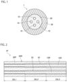
FIG. 1 is a cross-sectional view perpendicular to a longitudinal direction of an optical fiber manufactured by an optical fiber preform according to an embodiment of the present invention. -
FIG. 2 is a cross-sectional view in a longitudinal direction of an optical fiber preform for manufacturing the optical fiber illustrated inFIG. 1 . -
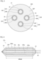
FIG. 3 is a cross-sectional view perpendicular to the longitudinal direction of the optical fiber preform illustrated inFIG. 2 . -
FIG. 4 is a view illustrating a state in which the optical fiber preform illustrated inFIG. 2 is subjected to fusing processing. -
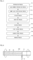
FIG. 5 is a flowchart illustrating processes in a method for manufacturing the optical fiber including a method for manufacturing the optical fiber preform according to the present embodiment. -
FIG. 6 is a view illustrating a state of a dummy glass tube welding process. -
FIG. 7 is a view illustrating a state of an etching process. -
FIG. 8 is a view illustrating a state after an insertion process. -
FIG. 9 is a view illustrating a state of a closing process. -
FIG. 10 is a view illustrating a state of a first fusing process. -
FIG. 11 is a view illustrating a state after the first fusing process. -
FIG. 12 is a view illustrating a state of a second fusing process. -
FIG. 13 is a view illustrating a state of a drawing process. -
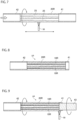
FIG. 14 is a view illustrating an optical fiber preform according to a modification, similarly toFIG. 2 . -
FIG. 15 is a view illustrating a state in which the optical fiber preform illustrated inFIG. 14 is subjected to fusing processing, similarly toFIG. 4 . - Hereinafter, modes for carrying out an optical fiber preform according to the present invention will be exemplified together with the accompanying drawings. The embodiments exemplified below are provided to facilitate understanding of the present invention, and are not intended to limit the present invention. The present invention can be modified and improved from the following embodiments without departing from the gist thereof. In addition, in the present specification, dimensions of members may be exaggerated for easy understanding.
-
FIG. 1 is a cross-sectional view perpendicular to a longitudinal direction of an optical fiber manufactured by an optical fiber preform according to an embodiment of the present invention. As illustrated inFIG. 1 , the optical fiber 1 according to the present embodiment is a multi-core fiber, and mainly includes a plurality ofcores 10, aclad 20 surrounding an outer peripheral surface of each of thecores 10, and acoating layer 30 coating an outer peripheral surface of theclad 20. In the present embodiment, the number ofcores 10 is four, and thecores 10 are arranged at substantially equal intervals on a circumference with the central axis of the optical fiber 1 being the center thereof. In addition, the outer shape of thecore 10 and the outer shape of theclad 20 in the cross section perpendicular to the longitudinal direction of the optical fiber are circular, but these outer shapes may be non-circular such as elliptical. In addition, the number ofcores 10 is not particularly limited, and for example, the optical fiber 1 may be a single-core fiber having onecore 10. - The
core 10 has a higher refractive index than the clad 20. In the present embodiment, thecore 10 is made of silica glass to which a dopant that increases the refractive index, such as germanium, is added, and the clad 20 is made of silica glass without any additive. Note that the core 10 may be made of silica glass without any additive, and the clad 20 may be made of silica glass to which a dopant that decreases the refractive index, such as fluorine (F), is added, and the dopant that changes the refractive index is not particularly limited. - The
coating layer 30 is made of, for example, a resin such as a thermosetting resin or an ultraviolet curable resin. -
FIG. 2 is a cross-sectional view in a longitudinal direction of an optical fiber preform for manufacturing the optical fiber 1 illustrated inFIG. 1 . As illustrated inFIG. 2 , theoptical fiber preform 1P is a rod assembly including a plurality of glass rods, and mainly includescore rods 10R and aclad rod 20R including a cladglass body 20P that constitutes at least a part of the clad 20 of the optical fiber 1 in the present embodiment. The number ofcore rods 10R is 4, which is the same as the number ofcores 10 of the optical fiber 1. -
FIG. 3 is a cross-sectional view perpendicular to the longitudinal direction of theoptical fiber preform 1P illustrated inFIG. 2 . As illustrated inFIG. 3 , thecore rods 10R have the same configuration, each including a rod-shapedcore glass body 10P that constitutes the core 10 as a predetermined portion different from the clad 20 in the optical fiber 1. Thecore rod 10R according to the present embodiment is a glass rod in which an outer peripheral surface of thecore glass body 10P is coated with a coating layer 10RL made of the same glass body as theclad glass body 20P, and the diameter of thecore rod 10R is substantially constant in the longitudinal direction. - As illustrated in
FIGS. 2 and3 , theclad rod 20R according to the present embodiment is made of theclad glass body 20P. The outer shape of the cross section of theclad rod 20R is circular, and the outer diameter of theclad rod 20R is substantially constant in the longitudinal direction. The length of theclad rod 20R is substantially the same as the length of thecore rod 10R. Theclad rod 20R has fourholes 25 extending along the longitudinal direction, and theseholes 25 correspond to the fourcore rods 10R on a one-to-one basis. Therefore, in a case where the number ofcore rods 10R is one, the number ofholes 25 provided in theclad rod 20R is one. Theseholes 25 are through holes whose both ends are opened to both end surfaces of theclad rod 20R. - The
core rod 10R is held in each of theholes 25. In the present embodiment, an end portion on one end side of theclad rod 20R surrounds an end portion on one end side of thecore rod 10R, and an end portion on the other end side of theclad rod 20R surrounds an end portion on the other end side of thecore rod 10R. Hereinafter, the end portion on one end side may be referred to as one end portion, and the end portion on the other end side may be referred to as the other end portion. The position of thehole 25 with respect to the central axis of theclad rod 20R is substantially similar to the position of the core 10 with respect to the central axis of the optical fiber 1. In addition, the diameter of eachhole 25 increases from one end side toward the other end side, and in the present embodiment, the diameter of eachhole 25 increases stepwise. The number of diameter change stages is not limited, and it is illustrated inFIG. 2 as an example that the diameter increases in two stages. - Such an
optical fiber preform 1P is used after being subjected to fusing processing in which both end portions are fused to form sealing portions for closing the ends of thehole 25 at both end portions of theclad rod 20R. - Next, the optical fiber preform subjected to fusing processing will be described.
-
FIG. 4 is a view illustrating a state in which theoptical fiber preform 1P illustrated inFIG. 2 is subjected to fusing processing, and is a cross-sectional view in the longitudinal direction of the optical fiber preform subjected to fusing processing. In the following description, in order to make it easy to distinguish the optical fiber preform 1Pa after the fusing processing and theoptical fiber preform 1P before the fusing processing, theoptical fiber preform 1P before the fusing processing will be referred to as a rod assembly. - As illustrated in
FIG. 4 , similarly to therod assembly 1P, the optical fiber preform 1Pa includes four core rods 10Ra and a clad rod 20Ra. - The core rod 10Ra is mainly different from the
core rod 10R of therod assembly 1P in that the length is shortened, and is a part of thecore rod 10R of therod assembly 1P. - The clad rod 20Ra is mainly different from the clad
rod 20R of therod assembly 1P in that the length is shortened, and afirst sealing portion 23, asecond sealing portion 24, and a main body portion 20RaB are included. The clad rod 20Ra has fourholes 25a extending along the longitudinal direction, and each of theholes 25a is a part of thehole 25 of theclad rod 20R of therod assembly 1P. The core rod 10Ra is held in each of theholes 25a. In addition, the diameter of eachhole 25a increases from one end side toward the other end side, and in the present embodiment, the diameter of eachhole 25a increases stepwise, and the number of change stages is two. - The clad rod 20Ra has a
first sealing portion 23 at the other end portion on the side where the diameter of thehole 25a is large, and has asecond sealing portion 24 at one end portion on the side where the diameter of thehole 25a is small, and the main body portion 20RaB is a portion between thefirst sealing portion 23 and thesecond sealing portion 24. The outer shape of the cross section of the main body portion 20RaB is circular, and the outer diameter of the main body portion 20RaB is substantially constant in the longitudinal direction. - The
first sealing portion 23 is formed in a tapered shape in which the outer diameter thereof decreases from one end side toward the other end side, and is welded to the other end portion of each core rod 10Ra while surrounding the other end portion of each core rod 10Ra to close the end on the other end side of eachhole 25a, and the core rod 10Ra is connected to thefirst sealing portion 23. A portion of the core rod 10Ra surrounded by thefirst sealing portion 23 is formed in a tapered shape in which the outer diameter thereof decreases from one end side toward the other end side. One end of asupport rod 40 made of silica glass is welded to a tip portion of thefirst sealing portion 23, and the central axis of thesupport rod 40 and the central axis of the clad rod 20Ra substantially coincide with each other. - The
second sealing portion 24 is formed in a tapered shape in which the outer diameter thereof decreases from the other end side toward the one end side, and is welded to one end portion of each core rod 10Ra while surrounding one end portion of each core rod 10Ra to close the end on one end side of eachhole 25a, and the core rod 10Ra is connected to thesecond sealing portion 24. A portion of the core rod 10Ra surrounded by thesecond sealing portion 24 is formed in a tapered shape in which the outer diameter thereof decreases from the other end side toward one end side. In this manner, both ends of eachhole 25a are closed by thefirst sealing portion 23 and thesecond sealing portion 24, and the inside of eachhole 25a is a closed space. The pressure in the space between the clad rod 20Ra and the core rod 10Ra, which is the space inside thehole 25a, is lower than the atmospheric pressure, and is, for example, about 10-5 Pa to 10-8 Pa. - Next, a method for manufacturing the optical fiber preform 1Pa and a method for manufacturing the optical fiber 1 will be described.
-
FIG. 5 is a flowchart illustrating processes in a method for manufacturing the optical fiber 1 including a method for manufacturing the optical fiber preform 1Pa according to the present embodiment. As illustrated inFIG. 5 , the method for manufacturing the optical fiber preform 1Pa according to the present embodiment includes a preparation process P1, a closing process P2, a first fusing process P3, and a second fusing process P4. The method for manufacturing the optical fiber 1 includes a drawing process P5 of drawing the manufactured optical fiber preform 1Pa. - This process is a process of preparing the
rod assembly 1P illustrated inFIG. 2 . This process according to the present embodiment includes a glass member preparation process P11, a dummy glass tube welding process P12, an etching process P13, and an insertion process P14. - This process is a process of preparing a plurality of glass members. The plurality of glass members prepared in the present embodiment are four
core rods 10R and aclad rod 20R included in therod assembly 1P. These members may be washed in advance using pure water, ethanol, hydrofluoric acid, or the like. - This process is a process of welding a dummy glass tube to each of both end surfaces of the
clad rod 20R prepared in the preparation process P1. The dummy glass tube according to the present embodiment is a cylindrical tube made of silica glass and having an outer diameter that is substantially the same as the outer diameter of theclad rod 20R. In the following description, the dummy glass tube welded to an end surface on the other end side, which is a side where the diameter of thehole 25 of theclad rod 20R is large, will be referred to as a first glass tube, and the dummy glass tube welded to an end surface on one end side, which is a side where the diameter of thehole 25 of theclad rod 20R is small, will be referred to as a second glass tube. -
FIG. 6 is a view illustrating a state of this process. The other end portion of theclad rod 20R is heated by an oxyhydrogen burner while theclad rod 20R is rotated about the central axis by a lathe (not illustrated) in a state where the central axis of theclad rod 20R is substantially horizontal. Next, afirst glass tube 41 disposed such that one end surface thereof faces the end surface on the other end side of theclad rod 20R with a predetermined interval is rotated around the central axis of thefirst glass tube 41 by the lathe (not illustrated). The rotation of theclad rod 20R and the rotation of thefirst glass tube 41 are synchronized, and in this state, the other end portion of theclad rod 20R and the end portion of thefirst glass tube 41 facing theclad rod 20R are heated by anoxyhydrogen burner 50. Next, one end surface of thefirst glass tube 41 is brought into abutment against the end surface on the other end side of theclad rod 20R, and thefirst glass tube 41 is welded to the end surface on the other end side of theclad rod 20R such that theclad rod 20R and thefirst glass tube 41 are substantially coaxial. Similarly to thefirst glass tube 41, a second glass tube is welded to the end surface on one end side of theclad rod 20R. In a state where thefirst glass tube 41 and the second glass tube are welded, an end on the other end side of eachhole 25 of theclad rod 20R is opened to an internal space of thefirst glass tube 41, and an end on one end side of eachhole 25 of theclad rod 20R is opened to an internal space of the second glass tube. - This process is a process of etching an inner peripheral surface defining each
hole 25 in theclad rod 20R.FIG. 7 is a view illustrating a state of this process. In the present embodiment, an etching gas such as a sulfur hexafluoride (SF6) gas flows from thesecond glass tube 42 into thehole 25 of theclad rod 20R to which theglass tubes clad rod 20R is rotated about the central axis by the lathe (not illustrated) in a state where the central axis is substantially horizontal. At this time, theoxyhydrogen burner 50 traverses along the longitudinal direction of theclad rod 20R to heat theclad rod 20R. In this manner, the inner peripheral surface defining thehole 25 is etched. The etching method is not particularly limited, and for example, etching may be performed with an etching solution such as hydrofluoric acid (HF) . - This process is a process of inserting the
core rods 10R prepared in the glass member preparation process P11 into theholes 25 of theclad rod 20R.FIG. 8 is a view illustrating a state after this process. In the present embodiment, first, a part of thefirst glass tube 41 is fused using theoxyhydrogen burner 50 to shorten thefirst glass tube 41. Next, eachcore rod 10R is inserted into thehole 25 corresponding to thecore rod 10R. In the present embodiment, thecore rod 10R is inserted into thehole 25 such that the other end portion of thecore rod 10R is surrounded by the other end portion of theclad rod 20R. Then, therod assembly 1P illustrated inFIG. 2 is obtained. In therod assembly 1P, thefirst glass tube 41 and thesecond glass tube 42 are welded to theclad rod 20R. In addition, since the length of theclad rod 20R and the length of thecore rod 10R are substantially the same, one end portion of thecore rod 10R is surrounded by one end portion of theclad rod 20R. - This process is a process of attaching a closing member to the end surface on the other end side of the
clad rod 20R to at least partially close the opening on the other end side of thehole 25.FIG. 9 is a view illustrating a state of this process. In the present embodiment, the closing member is acylindrical dummy rod 43 made of silica glass, and the diameter of thedummy rod 43 is smaller than the inner diameter of thefirst glass tube 41. As illustrated inFIG. 9 , thedummy rod 43 is inserted into the internal space of thefirst glass tube 41 such that one end surface of thedummy rod 43 comes into contact with the end surface on the other end side of theclad rod 20R. The central axis of theclad rod 20R and the central axis of thedummy rod 43 substantially coincide with each other. In this state, in the present embodiment, the opening on the other end side of eachhole 25 is entirely covered with thedummy rod 43. Next, the other end portion of therod assembly 1P, the end portion of thedummy rod 43 facing therod assembly 1P, and thefirst glass tube 41 are heated by theoxyhydrogen burner 50 while therod assembly 1P and thedummy rod 43 are synchronously rotated about the central axis by the lathe (not illustrated) in a state where the central axis is substantially horizontal. Then, thefirst glass tube 41 is welded to thedummy rod 43, and thedummy rod 43 is welded to the other end of therod assembly 1P. In this way, thedummy rod 43 is attached to the end surface on the other end side of theclad rod 20R, and as a result, in the present embodiment, the opening on the other end side of eachhole 25 of theclad rod 20R is entirely closed by thedummy rod 43 and thefirst glass tube 41. - This process is a process of fusing the other end portion of the
rod assembly 1P to form afirst sealing portion 23 that closes the other end side of thehole 25 at the other end portion of theclad rod 20R.FIG. 10 is a view illustrating a state of this process, andFIG. 11 is a view illustrating a state after this process. As illustrated inFIG. 10 , while the inside of eachhole 25 of theclad rod 20R of therod assembly 1P is evacuated by a vacuum pump (not illustrated) connected to thesecond glass tube 42, therod assembly 1P is rotated about the central axis of theclad rod 20R by the lathe (not illustrated) in a state where the central axis of theclad rod 20R is substantially horizontal. In this state, the other end portion of therod assembly 1P is heated by theoxyhydrogen burner 50 to evaporate the other end portion of theclad rod 20R from the outer peripheral surface side and form aconstricted portion 26 having a reduced outer diameter at the other end portion of theclad rod 20R. Then, thesecond glass tube 42 and thedummy rod 43 are moved to be relatively away in the longitudinal direction, and the other end portion of therod assembly 1P is fused with theconstricted portion 26 as a starting point to form afirst sealing portion 23 as illustrated inFIG. 11 . In the present embodiment, since the other end portion of theclad rod 20R surrounds the other end portion of thecore rod 10R, thecore rod 10R is positioned at the fused other end portion of therod assembly 1P, and the formed first sealingportion 23 is welded to thecore rod 10R. Then, one end of thesupport rod 40 is welded to a tip of thefirst sealing portion 23. - This process is a process of fusing one end portion of the
rod assembly 1P to form asecond sealing portion 24 that closes one end side of thehole 25 at one end portion of theclad rod 20R.FIG. 12 is a view illustrating a state of this process. As illustrated inFIG. 12 , similarly to the first fusing process P3, therod assembly 1P is rotated by the lathe (not illustrated) while the inside of eachhole 25 is evacuated by the vacuum pump (not illustrated). In this state, one end portion of therod assembly 1P is heated by theoxyhydrogen burner 50 to form aconstricted portion 27 having a reduced outer diameter at one end portion of theclad rod 20R. Then, thesecond glass tube 42 and thesupport rod 40 are moved to be relatively away in the longitudinal direction, and one end portion of therod assembly 1P is fused with theconstricted portion 27 as a starting point to form asecond sealing portion 24. In the present embodiment, since one end portion of theclad rod 20R surrounds one end portion of thecore rod 10R, the formed second sealingportion 24 is welded to thecore rod 10R. - As the
second sealing portion 24 is formed in this manner, theclad rod 20R of therod assembly 1P becomes the clad rod 20Ra of the optical fiber preform 1Pa, thehole 25 of theclad rod 20R of therod assembly 1P becomes thehole 25a of the clad rod 20Ra of the optical fiber preform 1Pa, and thecore rod 10R of therod assembly 1P becomes the core rod 10Ra of the optical fiber preform 1Pa, thereby obtaining the optical fiber preform 1Pa illustrated inFIG. 4 . - This process is a process of drawing the optical fiber preform 1Pa to obtain an optical fiber 1.
FIG. 13 is a view illustrating a state of this process. As illustrated inFIG. 13 , in this process, an end portion of the optical fiber preform 1Pa on the side opposite to thefirst sealing portion 23 side is heated by a spinningfurnace 60 to form a tapered melted portion ND in which the clad rod 20Ra and the core rod 10Ra are melted and integrated at the heated end portion, and glass is drawn from a tip of the melted portion ND. The melted portion ND closes an end of thehole 25a of the clad rod 20Ra on the side opposite to thefirst sealing portion 23 side. The glass drawn from the melted portion ND is immediately solidified, and thecore glass body 10P becomes the core 10 and theclad glass body 20P becomes the clad 20, thereby obtaining an optical fiberbare wire 1N including thecore 10 and the clad 20. Acoating layer 30 is provided on an outer peripheral surface of the optical fiberbare wire 1N by acoating device 70, thereby obtaining the optical fiber 1 illustrated inFIG. 1 . - As described above, the
rod assembly 1P, which is an optical fiber preform according to the present embodiment, includes aclad rod 20R and acore rod 10R as a glass rod. Theclad rod 20R has ahole 25 extending along a longitudinal direction with both ends thereof being opened, and thecore rod 10R is held in thehole 25. Thehole 25 of theclad rod 20R has a diameter that increases from one end side toward the other end side. For this reason, when therod assembly 1P is rotated about the center axis of theclad rod 20R in a state where the center axis of theclad rod 20R is substantially horizontal, thecore rod 10R may be inclined downward from one end side toward the other end side by its own weight. As a result, during such rotation, a force directed from one end side to the other end side may be applied to thecore rod 10R. In therod assembly 1P according to the present embodiment, the direction in which thecore rod 10R protrudes from thehole 25 of theclad rod 20R can be specified as the other end side. Therefore, as in the closing process P2 and the first fusing process P3 described above, even if the openings at both ends of thehole 25 are not closed before fusing processing, when one on the other end side of the openings of thehole 25 is closed, the closing member can close thecore rod 10R. By doing so, it is possible to suppress thecore rod 10R from protruding from thehole 25, and it is possible to suppress a decrease in processing efficiency as compared with the case where the openings at both ends are closed before fusing processing, thereby realizing arod assembly 1P capable of efficiently producing an optical fiber 1. In the closing process P2 and the first fusing process P3 described above, the opening on the other end side of thehole 25 is entirely closed. However, from the viewpoint of suppressing thecore rod 10R from protruding from thehole 25, the opening on the other end side of thehole 25 may be at least partially closed. - An inclination angle of the
core rod 10R with respect to the central axis of theclad rod 20R in a state where the central axis of theclad rod 20R is horizontal is preferably, for example, 0° or more and 0.1° or less. Further, in the present embodiment, the diameter of thehole 25 increases from one end side toward the other end side in a stepwise manner, but lengths 25L1, 25L2, and 25L3 of portions each having a constant diameter in thehole 25 are preferably, for example, 200 mm or more and 2000 mm or less. InFIG. 2 , the number of portions each having a constant diameter in thehole 25 is three, but the number of portions each having a constant diameter in thehole 25 is not limited to three in the present embodiment. In addition, in a case where thehole 25 becomes larger in the stepwise manner as described above, a diameter increase amount of thehole 25 at the portion where the diameter of thehole 25 increases is preferably, for example, 0.01 mm or more and 5 mm or less. - In addition, the optical fiber preform 1Pa according to the present embodiment includes a clad rod 20Ra and a core rod 10Ra as a glass rod. The clad rod 20Ra has a
hole 25a extending along a longitudinal direction, and the core rod 10Ra is held in thehole 25a. Thehole 25a has a diameter that increases from one end side toward the other end side. The clad rod 20Ra has afirst sealing portion 23 that closes an end on the other end side of thehole 25a at an end portion on the other end side thereof, and asecond sealing portion 24 that is welded to the core rod 10Ra at an end portion on one end side thereof to close an end on one end side of thehole 25a. When the optical fiber preform 1Pa according to the present embodiment is drawn from the end portion on thesecond sealing portion 24 side, a melted portion ND is formed at the end portion on thesecond sealing portion 24 side as illustrated inFIG. 13 . The melted portion ND closes the other end side of thehole 25a, and approaches thefirst sealing portion 23 side as the drawing progresses. In the optical fiber preform 1Pa according to the present embodiment, the size of thehole 25a increases from thesecond sealing portion 24 side toward thefirst sealing portion 23 side. Therefore, by drawing the optical fiber preform 1Pa according to the present embodiment from the end portion on thesecond sealing portion 24 side, it is possible to increase the space between the clad rod 20Ra and thecore rod 10R in a state where drawing has progressed without increasing the minimum diameter of thehole 25a as compared with the case where the diameter of thehole 25a is constant in the longitudinal direction. Therefore, the optical fiber preform 1Pa according to the present embodiment is capable of suppressing a positional deviation of the core 10 as a predetermined portion, and reducing a gas pressure increase in the space in a state where the drawing has progressed, making it possible to suppress an optical fiber 1 from including bubbles, as compared with the above-described case. Therefore, the optical fiber preform 1Pa according to the present embodiment is capable of efficiently producing an optical fiber 1. - In the optical fiber preform 1Pa according to the present embodiment, the
first sealing portion 23 is welded to the core rod 10Ra. If the optical fiber preform 1Pa is drawn from the end portion on thesecond sealing portion 24 side in a case where thefirst sealing portion 23 is not welded to the core rod 10Ra, the distance between the end on thefirst sealing portion 23 side of the core rod 10Ra and thefirst sealing portion 23 may vary during the drawing. In this case, the drawn amount of thecore glass body 10P per unit time varies, and the diameter of thecore 10 of the optical fiber 1 varies in the longitudinal direction. However, the optical fiber preform 1Pa according to the present embodiment is capable of suppressing the diameter of the core 10 from varying in the longitudinal direction as compared with the above-described case. - In the optical fiber preform 1Pa according to the present embodiment, the pressure in the
hole 25a is lower than the atmospheric pressure. Therefore, the optical fiber preform 1Pa according to the present embodiment is capable of reducing the pressure in the space between the clad rod 20Ra and the core rod 10Ra in a state where the drawing has progressed, making it possible to suppress an optical fiber 1 from including bubbles, as compared with the case where the pressure in thehole 25a is equal to or higher than the atmospheric pressure. Note that the pressure in thehole 25a may be equal to or higher than the atmospheric pressure. - In each of the
rod assembly 1P and the optical fiber preform 1Pa according to the present embodiment, a plurality ofcore rods 10R or 10Ra are provided, and a plurality ofholes core rods 10R or 10Ra are individually held are provided in theclad rod 20R or 20Ra. Therefore, as described above, therod assembly 1P and the optical fiber preform 1Pa according to the present embodiment is capable of manufacture an optical fiber 1 that is a multi-core fiber. - The method for manufacturing the optical fiber preform 1Pa according to the present embodiment includes a preparation process P1 and a first fusing process P3. In the preparation process P1, a
rod assembly 1P is prepared. In the first fusing process P3, when therod assembly 1P is rotated about the center axis of theclad rod 20R in a state where the opening on the other end side of thehole 25 is at least partially closed and the center axis of theclad rod 20R is substantially horizontal, the end portion on the other end side of therod assembly 1P is heated and fused. In the manufacturing method according to the present embodiment, since the diameter of thehole 25 of theclad rod 20R increases from one end side toward the other end side, even if the opening on one end side of thehole 25 is not closed in the first fusing process P3, thecore rod 10R can be suppressed from protruding from thehole 25. Therefore, the manufacturing method according to the present embodiment is capable of suppressing a decrease in processing efficiency as compared with the case where the openings at both ends of thehole 25 are closed in the first fusing process P3. - Although the present invention has been described by taking the above-described embodiment as an example, the present invention is not limited thereto.
- For example, in the embodiment described above, the
clad rod 20R or 20Ra in which the diameter of thehole hole FIGS. 14 and15 , the diameter of thehole hole hole FIG. 14 is a view illustrating anoptical fiber preform 1P according to a modification similarly toFIG. 2 , and theoptical fiber preform 1P illustrated inFIG. 14 is arod assembly 1P before fusing processing.FIG. 15 is a view illustrating a state in which theoptical fiber preform 1P illustrated inFIG. 14 is subjected to fusing processing, similarly toFIG. 4 . In therod assembly 1P according to the present modification, similarly to the above-described embodiment, when therod assembly 1P is rotated about the central axis of theclad rod 20R in a state where the central axis of theclad rod 20R is substantially horizontal, thecore rod 10R can be suppressed from protruding from thehole 25 by closing one on the other end side of the openings of thehole 25. In addition, the optical fiber preform 1Pa according to the present modification is capable of suppressing an optical fiber 1 from including bubbles, similarly to the above-described embodiment. - In the embodiment described above, the
clad rod 20R or 20Ra constituted by theclad glass body 20P has been described as an example. However, theclad rod 20R or 20Ra only needs to include theclad glass body 20P, and may further include a predetermined glass body that constitutes a predetermined portion different from the clad 20 in the optical fiber 1. Examples of such a predetermined portion include acore 10, a marker, and a stress applying portion that applies stress to thecore 10. In addition, theclad rod 20R may have an empty hole extending along the longitudinal direction with no glass rod being accommodated therein. - In the embodiment described above, the
rod assembly 1P including thecore rod 10R as a glass rod and the optical fiber preform 1Pa including the core rod 10Ra as a glass rod have been described as an example. However, the glass rod included in therod assembly 1P or the optical fiber preform 1Pa only needs to be a glass rod including a predetermined glass body that constitutes a predetermined portion different from the clad 20 in the optical fiber 1. For example, the predetermined glass body included in the glass rod may be a glass body that constitutes a marker as the predetermined portion or a glass body that constitutes a stress applying portion as the predetermined portion. The glass rod may be a glass rod in which a core glass body that constitutes acore 10 is covered with a glass body that constitutes a low refractive index layer surrounding thecore 10. In addition, when there are a plurality of glass rods, a predetermined glass body included in at least one of the plurality of glass rods may be different from a predetermined glass body included in at least one other glass rod of the plurality of glass rods. - In the embodiment described above, the
oxyhydrogen burner 50 is used for heating the glass member. However, the heating device for heating the glass member is not particularly limited, and may be, for example, an electric furnace or the like. From the viewpoint of reducing processing waste, it is preferable that therod assembly 1P is fused by theoxyhydrogen burner 50 in the first fusing process P3 and the second fusing process P4. In general, the heat spot of the oxyhydrogen burner is narrower than the heat spot of the electric furnace. Therefore, by using the oxyhydrogen burner, the sizes of the constrictedportions first sealing portion 23 and thesecond sealing portion 24 and reducing processing waste, as compared with the case where the electric furnace is used. The heating source may be light having a high absorptivity with respect to glass such as a CO2 laser. When the laser is used as a heat source, the heat spots can be arbitrarily distributed, making it possible to realize heating optimum for the size and material of the preform. - In the embodiment described above, the
rod assembly 1P in which both end portions of theclad rod 20R surround the end portions of thecore rod 10R has been described as an example. However, at least one of both ends of theclad rod 20R may not surround thecore rod 10R. However, from the viewpoint of reducing processing waste, it is preferable that one end portion of theclad rod 20R surrounds one end portion of thecore rod 10R, and the other end portion of theclad rod 20R surrounds the other end portion of thecore rod 10R. - In the method for manufacturing the optical fiber preform 1Pa according to the embodiment described above, the preparation process P1 including the glass member preparation process P11, the dummy glass tube welding process P12, the etching process P13, and the insertion process P14 has been described as an example. However, the preparation process P1 is not particularly limited as long as the
rod assembly 1P can be prepared. For example, in a case where aclad rod 20R of which an inner peripheral surface defining ahole 25 is etched is prepared, the etching process P13 may be omitted. In addition, the closing process P2 of entirely closing the opening on one end side of thehole 25 of theclad rod 20R with thedummy rod 43 as a closing member has been described as an example. However, in the closing process P2, the opening on one end side of thehole 25 may be at least partially closed, and the closing member is not limited. - According to the present invention, an optical fiber preform capable of efficiently producing an optical fiber is provided, and can be used in various fields related to optical fibers.
Claims (5)
- An optical fiber preform comprising:a clad rod having a hole extending along a longitudinal direction with both ends being opened, and including a clad glass body that constitutes at least a part of a clad in an optical fiber; anda glass rod including a predetermined glass body that constitutes a predetermined portion different from the clad in the optical fiber, the glass rod being held in the hole,wherein the hole has a diameter that increases from one end side toward other end side.
- An optical fiber preform comprising:a clad rod having a hole extending along a longitudinal direction, and including a clad glass body that constitutes at least a part of a clad in an optical fiber; anda glass rod including a predetermined glass body that constitutes a predetermined portion different from the clad in the optical fiber, the glass rod being held in the hole,wherein the hole has a diameter that increases from one end side toward other end side, andthe clad rod includes a first sealing portion welded to the glass rod at an end portion on the other end side thereof to close an end on the other end side of the hole, and a second sealing portion welded to the glass rod at an end portion on the one end side to close an end on the one end side of the hole.
- The optical fiber preform according to claim 1 or 2, wherein
the diameter of the hole increases from the one end side toward the other end side in a stepwise manner. - The optical fiber preform according to claim 1 or 2, wherein
the diameter of the hole gradually increases from the one end side toward the other end side. - The optical fiber preform according to claim 1 or 2, whereina plurality of glass rods are provided, anda plurality of holes in which the plurality of glass rods are individually held are provided in the clad rod.
Applications Claiming Priority (2)
| Application Number | Priority Date | Filing Date | Title |
|---|---|---|---|
| JP2022025998 | 2022-02-22 | ||
| PCT/JP2023/004929 WO2023162775A1 (en) | 2022-02-22 | 2023-02-14 | Optical fiber preform |
Publications (2)
| Publication Number | Publication Date |
|---|---|
| EP4484387A1 true EP4484387A1 (en) | 2025-01-01 |
| EP4484387A4 EP4484387A4 (en) | 2026-02-18 |
Family
ID=87765831
Family Applications (1)
| Application Number | Title | Priority Date | Filing Date |
|---|---|---|---|
| EP23759777.8A Pending EP4484387A4 (en) | 2022-02-22 | 2023-02-14 | PREFORM FOR OPTICAL FIBERS |
Country Status (5)
| Country | Link |
|---|---|
| US (1) | US20250162925A1 (en) |
| EP (1) | EP4484387A4 (en) |
| JP (1) | JP7777669B2 (en) |
| CN (1) | CN118414317A (en) |
| WO (1) | WO2023162775A1 (en) |
Family Cites Families (8)
| Publication number | Priority date | Publication date | Assignee | Title |
|---|---|---|---|---|
| JP3376422B2 (en) * | 1993-09-20 | 2003-02-10 | 日本電信電話株式会社 | Glass jacket tube manufacturing apparatus and optical fiber manufacturing method |
| US7143611B2 (en) * | 2003-09-19 | 2006-12-05 | Fitel Usa Corp | Rod-In-Tube optical fiber preform assembly and method having reduced movement |
| DE102004014345B4 (en) * | 2004-03-22 | 2007-09-20 | Heraeus Tenevo Gmbh | Method for producing an optical component |
| JP2011228541A (en) * | 2010-04-21 | 2011-11-10 | Photonic Science Technology Inc | Method of manufacturing tapered optical fiber |
| US20140186645A1 (en) * | 2013-01-02 | 2014-07-03 | Ofs Fitel, Llc | Manufacture of bend insensitive multimode optical fiber |
| JP6151310B2 (en) * | 2015-07-02 | 2017-06-21 | 株式会社フジクラ | Optical fiber preform manufacturing method and optical fiber manufacturing method |
| CN110709362B (en) * | 2017-08-09 | 2022-03-15 | 株式会社藤仓 | Manufacturing method of optical fiber base material, optical fiber base material, and manufacturing method of optical fiber |
| JP7068945B2 (en) * | 2017-08-09 | 2022-05-17 | 株式会社フジクラ | Manufacturing method of optical fiber base material, manufacturing method of optical fiber base material, optical fiber |
-
2023
- 2023-02-14 EP EP23759777.8A patent/EP4484387A4/en active Pending
- 2023-02-14 JP JP2024503046A patent/JP7777669B2/en active Active
- 2023-02-14 CN CN202380015287.2A patent/CN118414317A/en active Pending
- 2023-02-14 US US18/840,253 patent/US20250162925A1/en active Pending
- 2023-02-14 WO PCT/JP2023/004929 patent/WO2023162775A1/en not_active Ceased
Also Published As
| Publication number | Publication date |
|---|---|
| JPWO2023162775A1 (en) | 2023-08-31 |
| JP7777669B2 (en) | 2025-11-28 |
| CN118414317A (en) | 2024-07-30 |
| US20250162925A1 (en) | 2025-05-22 |
| EP4484387A4 (en) | 2026-02-18 |
| WO2023162775A1 (en) | 2023-08-31 |
Similar Documents
| Publication | Publication Date | Title |
|---|---|---|
| CN103936277B (en) | Multi-core optical fiber manufacturing method | |
| CN102016667A (en) | Fibre coupler | |
| US5944867A (en) | Method of manufacturing a multi-core optical fiber | |
| EP3180293B1 (en) | Method for forming a quartz glass optical component and system | |
| JP2007534592A (en) | Optical fibers, their preforms, and their manufacturing methods and equipment | |
| US12001050B2 (en) | Manufacturing method of multicore fiber preform, multicore fiber preform, and multicore fiber | |
| JP5435504B2 (en) | Method for manufacturing preform for optical fiber | |
| CN114355505B (en) | A kind of laser shaping optical fiber, its preparation method and application | |
| US9733424B2 (en) | Multicore fiber and method of manufacturing the same | |
| CN103153889B (en) | Method for preparing preform, method for producing optical fiber, and optical fiber | |
| EP4484387A1 (en) | Optical fiber preform | |
| EP0352957B1 (en) | Method of reproducibly making fiber optic coupler | |
| US20240217860A1 (en) | Process of making multi-core fiber preform by integrating core rods and cladding cylinder | |
| EP4463426A1 (en) | Reduction of multi-core fiber preform geometric distortion | |
| JP7842580B2 (en) | optical fiber base material | |
| JP7853115B2 (en) | optical fiber base material | |
| US12459853B2 (en) | Multi-core optical fiber preform, multi-core optical fiber preform production method, and multi-core optical fiber production method | |
| JP7829384B2 (en) | Clad rod, method for manufacturing a preform for optical fibers using the same, and method for manufacturing optical fibers | |
| WO2012111436A1 (en) | Method for manufacturing optical fibers | |
| US12358829B2 (en) | Method for manufacturing a preform for a multi-core optical fiber and method for manufacturing multi-core optical fibers | |
| JP6517583B2 (en) | Method of manufacturing base material for multi-core fiber, and method of manufacturing multi-core fiber using the same | |
| CN111051258B (en) | Method for producing a glass fiber preform having a core with a polygonal core cross section | |
| WO2025070794A1 (en) | Method for producing anti-resonant fiber preform and method for producing anti-resonant fiber | |
| JP3815169B2 (en) | Microstructured optical fiber preform and method of manufacturing microstructured optical fiber | |
| JP7144348B2 (en) | Method for manufacturing optical fiber preform and method for manufacturing optical fiber |
Legal Events
| Date | Code | Title | Description |
|---|---|---|---|
| STAA | Information on the status of an ep patent application or granted ep patent |
Free format text: STATUS: THE INTERNATIONAL PUBLICATION HAS BEEN MADE |
|
| PUAI | Public reference made under article 153(3) epc to a published international application that has entered the european phase |
Free format text: ORIGINAL CODE: 0009012 |
|
| STAA | Information on the status of an ep patent application or granted ep patent |
Free format text: STATUS: REQUEST FOR EXAMINATION WAS MADE |
|
| 17P | Request for examination filed |
Effective date: 20240906 |
|
| AK | Designated contracting states |
Kind code of ref document: A1 Designated state(s): AL AT BE BG CH CY CZ DE DK EE ES FI FR GB GR HR HU IE IS IT LI LT LU LV MC ME MK MT NL NO PL PT RO RS SE SI SK SM TR |
|
| DAV | Request for validation of the european patent (deleted) | ||
| DAX | Request for extension of the european patent (deleted) | ||
| A4 | Supplementary search report drawn up and despatched |
Effective date: 20260119 |
|
| RIC1 | Information provided on ipc code assigned before grant |
Ipc: C03B 37/012 20060101AFI20260113BHEP |