EP4484339A1 - Article transfer apparatus - Google Patents
Article transfer apparatus Download PDFInfo
- Publication number
- EP4484339A1 EP4484339A1 EP24180015.0A EP24180015A EP4484339A1 EP 4484339 A1 EP4484339 A1 EP 4484339A1 EP 24180015 A EP24180015 A EP 24180015A EP 4484339 A1 EP4484339 A1 EP 4484339A1
- Authority
- EP
- European Patent Office
- Prior art keywords
- unit
- article
- articles
- conveyor
- alignment
- Prior art date
- Legal status (The legal status is an assumption and is not a legal conclusion. Google has not performed a legal analysis and makes no representation as to the accuracy of the status listed.)
- Pending
Links
- 238000011144 upstream manufacturing Methods 0.000 claims abstract description 14
- 238000001514 detection method Methods 0.000 claims description 45
- 230000005856 abnormality Effects 0.000 claims description 4
- 230000008859 change Effects 0.000 abstract description 2
- 230000032258 transport Effects 0.000 description 25
- 238000000034 method Methods 0.000 description 11
- 230000008569 process Effects 0.000 description 11
- 230000002265 prevention Effects 0.000 description 10
- 230000004048 modification Effects 0.000 description 7
- 238000012986 modification Methods 0.000 description 7
- 238000007689 inspection Methods 0.000 description 3
- 238000011109 contamination Methods 0.000 description 2
- 238000010586 diagram Methods 0.000 description 2
- 230000005484 gravity Effects 0.000 description 1
- 238000009434 installation Methods 0.000 description 1
- 238000004806 packaging method and process Methods 0.000 description 1
- 230000009467 reduction Effects 0.000 description 1
- 238000005303 weighing Methods 0.000 description 1
Images



Classifications
-
- B—PERFORMING OPERATIONS; TRANSPORTING
- B65—CONVEYING; PACKING; STORING; HANDLING THIN OR FILAMENTARY MATERIAL
- B65G—TRANSPORT OR STORAGE DEVICES, e.g. CONVEYORS FOR LOADING OR TIPPING, SHOP CONVEYOR SYSTEMS OR PNEUMATIC TUBE CONVEYORS
- B65G47/00—Article or material-handling devices associated with conveyors; Methods employing such devices
- B65G47/02—Devices for feeding articles or materials to conveyors
- B65G47/04—Devices for feeding articles or materials to conveyors for feeding articles
- B65G47/12—Devices for feeding articles or materials to conveyors for feeding articles from disorderly-arranged article piles or from loose assemblages of articles
- B65G47/14—Devices for feeding articles or materials to conveyors for feeding articles from disorderly-arranged article piles or from loose assemblages of articles arranging or orientating the articles by mechanical or pneumatic means during feeding
- B65G47/1492—Devices for feeding articles or materials to conveyors for feeding articles from disorderly-arranged article piles or from loose assemblages of articles arranging or orientating the articles by mechanical or pneumatic means during feeding the articles being fed from a feeding conveyor
-
- B—PERFORMING OPERATIONS; TRANSPORTING
- B65—CONVEYING; PACKING; STORING; HANDLING THIN OR FILAMENTARY MATERIAL
- B65G—TRANSPORT OR STORAGE DEVICES, e.g. CONVEYORS FOR LOADING OR TIPPING, SHOP CONVEYOR SYSTEMS OR PNEUMATIC TUBE CONVEYORS
- B65G47/00—Article or material-handling devices associated with conveyors; Methods employing such devices
- B65G47/22—Devices influencing the relative position or the attitude of articles during transit by conveyors
- B65G47/26—Devices influencing the relative position or the attitude of articles during transit by conveyors arranging the articles, e.g. varying spacing between individual articles
- B65G47/30—Devices influencing the relative position or the attitude of articles during transit by conveyors arranging the articles, e.g. varying spacing between individual articles during transit by a series of conveyors
- B65G47/31—Devices influencing the relative position or the attitude of articles during transit by conveyors arranging the articles, e.g. varying spacing between individual articles during transit by a series of conveyors by varying the relative speeds of the conveyors forming the series
-
- B—PERFORMING OPERATIONS; TRANSPORTING
- B65—CONVEYING; PACKING; STORING; HANDLING THIN OR FILAMENTARY MATERIAL
- B65G—TRANSPORT OR STORAGE DEVICES, e.g. CONVEYORS FOR LOADING OR TIPPING, SHOP CONVEYOR SYSTEMS OR PNEUMATIC TUBE CONVEYORS
- B65G43/00—Control devices, e.g. for safety, warning or fault-correcting
- B65G43/08—Control devices operated by article or material being fed, conveyed or discharged
-
- B—PERFORMING OPERATIONS; TRANSPORTING
- B65—CONVEYING; PACKING; STORING; HANDLING THIN OR FILAMENTARY MATERIAL
- B65G—TRANSPORT OR STORAGE DEVICES, e.g. CONVEYORS FOR LOADING OR TIPPING, SHOP CONVEYOR SYSTEMS OR PNEUMATIC TUBE CONVEYORS
- B65G47/00—Article or material-handling devices associated with conveyors; Methods employing such devices
- B65G47/34—Devices for discharging articles or materials from conveyor
- B65G47/46—Devices for discharging articles or materials from conveyor and distributing, e.g. automatically, to desired points
- B65G47/51—Devices for discharging articles or materials from conveyor and distributing, e.g. automatically, to desired points according to unprogrammed signals, e.g. influenced by supply situation at destination
- B65G47/5104—Devices for discharging articles or materials from conveyor and distributing, e.g. automatically, to desired points according to unprogrammed signals, e.g. influenced by supply situation at destination for articles
-
- B—PERFORMING OPERATIONS; TRANSPORTING
- B65—CONVEYING; PACKING; STORING; HANDLING THIN OR FILAMENTARY MATERIAL
- B65G—TRANSPORT OR STORAGE DEVICES, e.g. CONVEYORS FOR LOADING OR TIPPING, SHOP CONVEYOR SYSTEMS OR PNEUMATIC TUBE CONVEYORS
- B65G47/00—Article or material-handling devices associated with conveyors; Methods employing such devices
- B65G47/52—Devices for transferring articles or materials between conveyors i.e. discharging or feeding devices
- B65G47/525—Devices for transferring articles or materials between conveyors i.e. discharging or feeding devices using fluid jets
-
- B—PERFORMING OPERATIONS; TRANSPORTING
- B65—CONVEYING; PACKING; STORING; HANDLING THIN OR FILAMENTARY MATERIAL
- B65G—TRANSPORT OR STORAGE DEVICES, e.g. CONVEYORS FOR LOADING OR TIPPING, SHOP CONVEYOR SYSTEMS OR PNEUMATIC TUBE CONVEYORS
- B65G47/00—Article or material-handling devices associated with conveyors; Methods employing such devices
- B65G47/74—Feeding, transfer, or discharging devices of particular kinds or types
- B65G47/76—Fixed or adjustable ploughs or transverse scrapers
- B65G47/766—Adjustable ploughs or transverse scrapers
-
- B—PERFORMING OPERATIONS; TRANSPORTING
- B65—CONVEYING; PACKING; STORING; HANDLING THIN OR FILAMENTARY MATERIAL
- B65G—TRANSPORT OR STORAGE DEVICES, e.g. CONVEYORS FOR LOADING OR TIPPING, SHOP CONVEYOR SYSTEMS OR PNEUMATIC TUBE CONVEYORS
- B65G47/00—Article or material-handling devices associated with conveyors; Methods employing such devices
- B65G47/74—Feeding, transfer, or discharging devices of particular kinds or types
- B65G47/82—Rotary or reciprocating members for direct action on articles or materials, e.g. pushers, rakes, shovels
-
- B—PERFORMING OPERATIONS; TRANSPORTING
- B65—CONVEYING; PACKING; STORING; HANDLING THIN OR FILAMENTARY MATERIAL
- B65G—TRANSPORT OR STORAGE DEVICES, e.g. CONVEYORS FOR LOADING OR TIPPING, SHOP CONVEYOR SYSTEMS OR PNEUMATIC TUBE CONVEYORS
- B65G2203/00—Indexing code relating to control or detection of the articles or the load carriers during conveying
- B65G2203/02—Control or detection
- B65G2203/0208—Control or detection relating to the transported articles
- B65G2203/0225—Orientation of the article
-
- B—PERFORMING OPERATIONS; TRANSPORTING
- B65—CONVEYING; PACKING; STORING; HANDLING THIN OR FILAMENTARY MATERIAL
- B65G—TRANSPORT OR STORAGE DEVICES, e.g. CONVEYORS FOR LOADING OR TIPPING, SHOP CONVEYOR SYSTEMS OR PNEUMATIC TUBE CONVEYORS
- B65G2203/00—Indexing code relating to control or detection of the articles or the load carriers during conveying
- B65G2203/02—Control or detection
- B65G2203/0208—Control or detection relating to the transported articles
- B65G2203/0241—Quantity of articles
-
- B—PERFORMING OPERATIONS; TRANSPORTING
- B65—CONVEYING; PACKING; STORING; HANDLING THIN OR FILAMENTARY MATERIAL
- B65G—TRANSPORT OR STORAGE DEVICES, e.g. CONVEYORS FOR LOADING OR TIPPING, SHOP CONVEYOR SYSTEMS OR PNEUMATIC TUBE CONVEYORS
- B65G2203/00—Indexing code relating to control or detection of the articles or the load carriers during conveying
- B65G2203/04—Detection means
- B65G2203/041—Camera
-
- B—PERFORMING OPERATIONS; TRANSPORTING
- B65—CONVEYING; PACKING; STORING; HANDLING THIN OR FILAMENTARY MATERIAL
- B65G—TRANSPORT OR STORAGE DEVICES, e.g. CONVEYORS FOR LOADING OR TIPPING, SHOP CONVEYOR SYSTEMS OR PNEUMATIC TUBE CONVEYORS
- B65G47/00—Article or material-handling devices associated with conveyors; Methods employing such devices
- B65G47/02—Devices for feeding articles or materials to conveyors
- B65G47/04—Devices for feeding articles or materials to conveyors for feeding articles
- B65G47/06—Devices for feeding articles or materials to conveyors for feeding articles from a single group of articles arranged in orderly pattern, e.g. workpieces in magazines
- B65G47/08—Devices for feeding articles or materials to conveyors for feeding articles from a single group of articles arranged in orderly pattern, e.g. workpieces in magazines spacing or grouping the articles during feeding
Definitions
- the present disclosure relates to an article transfer apparatus.
- Patent Document 1 JP-A No. 2018-154468 discloses an apparatus where articles conveyed thereto in a first direction by a first conveyor are aligned on a second conveyor, form an article group, and are conveyed in a second direction.
- an article transfer apparatus is desired in which the operation of aligning the articles is not hindered even when the supply intervals of the articles change.
- An article transfer apparatus of a first aspect includes a conveyance unit, an alignment unit, a sorting unit, and a control unit.
- the conveyance unit conveys articles.
- the alignment unit collects and aligns a predetermined number of the articles conveyed thereto from the conveyance unit to form an article group.
- the sorting unit sorts the articles off the conveyance unit before the articles on the conveyance unit reach the alignment unit.
- the control unit determines whether the articles heading to the alignment unit can be aligned in the alignment unit and, when it determines that the articles cannot be aligned, sorts the articles via the sorting unit.
- the aligned orientation of the articles becomes disturbed. Therefore, articles determined to be unable to be aligned by the alignment unit are sorted on the conveyance unit and are not allowed to reach the alignment unit, whereby disturbances in the aligned orientation of the articles are avoided beforehand.
- An article transfer apparatus of a second aspect is the article transfer apparatus of the first aspect, wherein the alignment unit includes an alignment conveyor. Each time the alignment conveyor receives one of the articles from the conveyance unit, it conveys that article a predetermined distance in one direction, stops, and waits to receive a trailing article.
- An article transfer apparatus of a third aspect is the article transfer apparatus of the first aspect or the second aspect, further including a first detection unit.
- the first detection unit detects supply intervals of the articles supplied to the conveyance unit. When the supply intervals are equal to or less than a first threshold, the control unit sorts the articles off the conveyance unit via the sorting unit.
- An article transfer apparatus of a fourth aspect is the article transfer apparatus of the third aspect, further including a second detection unit.
- the second detection unit detects a queued number of the articles in the alignment unit.
- a plurality of the article groups can be aligned in the alignment unit.
- the control unit sorts the articles off the conveyance unit via the sorting unit regardless of the supply intervals of the articles supplied to the conveyance unit.
- the articles on the conveyance unit are sorted off the conveyance unit regardless of the supply intervals of the articles supplied to the conveyance unit, whereby hindrances to the alignment of the articles in the alignment unit are avoided.
- An article transfer apparatus of a fifth aspect is the article transfer apparatus of the fourth aspect, wherein the control unit doubles as the second detection unit.
- the control unit calculates the queued number of the articles based on the number of alignment operations in the alignment unit.
- An article transfer apparatus of a sixth aspect is the article transfer apparatus of the fourth aspect, wherein the second detection unit is a camera.
- the control unit comprehends the queued number of the articles from an image obtained by the camera.
- An article transfer apparatus of a seventh aspect is the article transfer apparatus of any one of the first aspect to the sixth aspect, wherein the sorting unit includes an air nozzle, an air supply source, and a valve.
- the air nozzle jets air toward the articles.
- the air supply source supplies air to the air nozzle.
- the valve is connected between the air nozzle and the air supply source.
- the control unit controls the switching on and off of the valve to thereby switch between causing air to be jetted from the air nozzle and stopping air from being jetted from the air nozzle. In this article transfer apparatus, installation is easy and space is saved.
- An article transfer apparatus of an eighth aspect is the article transfer apparatus of any one of the first aspect to the sixth aspect, wherein the sorting unit has a swinging member.
- the swinging member swings between a standby position in which it does not interfere with the articles on the conveyance unit and an operative position in which it hits the articles on the conveyance unit and guides the articles off the conveyance unit.
- An article transfer apparatus of a ninth aspect is the article transfer apparatus of any one of the first aspect to the eighth aspect, wherein the sorting unit sorts the articles off the conveyance unit in a zone between an upstream end and a middle of the conveyance unit.
- An article transfer apparatus of a tenth aspect is the article transfer apparatus of any one of the first aspect to the ninth aspect, further including transporting means for transporting the article group to a predetermined position.
- the predetermined position is movable. Even if an abnormality occurs in the movement of the predetermined position, the conveyance of the articles from the conveyance unit to the alignment unit is continued.
- articles determined to be unable to be aligned by the alignment unit are sorted on the conveyance unit and are not allowed to reach the alignment unit, whereby disturbances in the aligned orientation of the articles are avoided beforehand.
- FIG. 1 is a schematic perspective view showing configurations of an article transfer apparatus 1.
- a weighing apparatus and a bagmaking and packaging machine not shown in the drawings are disposed.
- To the article transfer apparatus 1 are supplied only bags G that have passed weight, seal, and contamination inspections in the upstream process.
- the article transfer apparatus 1 is configured by an article conveyance unit 10, an article alignment unit 20, an article transport unit 30, an article detection unit 60, and an article sorting unit 70.
- the article conveyance unit 10 receives the bags G and conveys them to the article alignment unit 20.
- the article alignment unit 20 aligns the bags G supplied from the article conveyance unit 10.
- the article transport unit 30 collectively transports to a container 40 a plurality of the bags G aligned by the article alignment unit 20.
- the article sorting unit 70 sorts the bags G off the article conveyance unit 10 in cases where it is determined that the bags G heading to the article alignment unit 20 cannot be aligned in the article alignment unit 20.
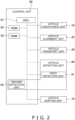
- FIG. 2 is a control block diagram of the article transfer apparatus 1.
- a control unit 80 controls operations of drive parts of the article conveyance unit 10, the article alignment unit 20, the article transport unit 30, and the article sorting unit 70 of the article transfer apparatus 1.
- the control unit 80 includes a CPU 81 and a ROM 82 and a RAM 83 that are connected to the CPU 81.
- the article conveyance unit 10 has an article introduction conveyor 11, an infeed conveyor 12, a support conveyor 13, and an orientation changing conveyor 14.
- the article introduction conveyor 11 receives a supply of the bags G that have passed the weight, seal, and contamination inspections and guides the bags G to the infeed conveyor 12.
- the infeed conveyor 12 conveys the bags G conveyed thereto from the article introduction conveyor 11 to the article alignment unit 20.
- the conveyance surface of the infeed conveyor 12 is inclined in a clockwise direction when its downstream side is seen from its upstream side in the conveyance direction of the bags G.
- the orientation of each of the bags G when switching from the infeed conveyor 12 to an alignment conveyor 21 is inclined in such a way that the part of the bag G that lands on the bag G already placed on the alignment conveyor 21 is up and the part of the bag G that lands directly on the alignment conveyor 21 is down.
- the infeed conveyor 12 is extensible and retractable.
- the surface of the infeed conveyor 12 contacting the bags G is instantaneously removed.
- FIG. 3 is a perspective view of the article transfer apparatus 1 in which the infeed conveyor 12 is seen from the alignment conveyor 21 side in a state in which the surface of the infeed conveyor 12 contacting a bag G is instantaneously removed.
- FIG. 4 is a front elevation view of the orientation of a bag G when the bag G drops from the infeed conveyor 12 in a case where the surface of the infeed conveyor 12 contacting the bag G is instantaneously removed.
- a leading end portion roller R1 of the infeed conveyor 12 moves a distance D1 in a direction X2 opposite the conveyance direction (a first direction X1).
- an intermediate roller R2 of the infeed conveyor 12 also moves the distance D1 in the direction X2 in conjunction therewith, thereby absorbing slack in the conveyor belt when the leading end portion roller R1 moves in the direction X2.
- the bag G suddenly loses the drag from the conveyance surface of the infeed conveyor 12 but due to inertia maintains the orientation that it had while it was being conveyed.
- the bag G easily maintains its orientation when it leaves the infeed conveyor 12, and a disturbance in orientation when the bag G lands on the alignment conveyor 21 is inhibited.
- the support conveyor 13 is disposed on the lower end portion in the direction of inclination of the infeed conveyor 12.
- the conveyance surface of the support conveyor 13 and the conveyance surface of the infeed conveyor 12 are orthogonal to each other.
- the bags G moving on the conveyance surface of the infeed conveyor 12 are subjected to a component of the force of gravity along the direction of inclination, so they move while sliding downward toward the support conveyor 13 and thereafter move along the support conveyor 13.
- the conveyance surface of the support conveyor 13 moves along the advancing direction of the conveyance surface of the infeed conveyor 12 so as to not hinder the conveyance of the bags G.
- the orientation changing conveyor 14 is disposed on the upper end portion in the direction of inclination of the infeed conveyor 12.
- the orientation changing conveyor 14 is disposed in such a way as to oppose the support conveyor 13 on the conveyance surface of the infeed conveyor 12.
- the downstream end of the orientation changing conveyor 14 in the conveyance direction is in a position nearer to the support conveyor 13 than the upstream end.
- the bags G rotate in a counterclockwise direction about the point of contact and the orientation of the bags G changes so that long sides of the bags G are oriented obliquely downward along the orientation changing conveyor 14. Thereafter, the bags G hit the support conveyor 13, changing orientation so that the long sides of the bags G are along the support conveyor 13, and head to the alignment conveyor 21.
- the article alignment unit 20 has the alignment conveyor 21, an outfeed conveyor 22, and a rotation prevention conveyor 23.
- the alignment conveyor 21 and the infeed conveyor 12 are arranged in such a way that their conveyance surfaces are orthogonal to each other. Each time the alignment conveyor 21 catches one bag G, it conveys that bag G a fixed distance toward the outfeed conveyor 22.
- the bag G moves the fixed distance closer to the outfeed conveyor 22 from the position where it dropped. A part of the bag G that comes dropping thereafter lands on the alignment conveyor 21 while the remaining part inclines against the preceding bag G. Therefore, the bags G on the alignment conveyor 21 form a line in such a way that mutually adjacent bags partially lie on top of each other.
- the alignment conveyor 21 and the outfeed conveyor 22 simultaneously start operating, and the alignment conveyor 21 and the outfeed conveyor 22 perform a conveyance operation in the same direction.
- N-number of the bags G aligned in a line on the alignment conveyor 21 move as one article group to the outfeed conveyor 22, and the article group that was already on the outfeed conveyor 22 further advances on the outfeed conveyor 22.
- the rotation prevention conveyor 23 is disposed in a substantially vertical orientation so as to oppose the terminal end of the infeed conveyor 12. Specifically, the rotation prevention conveyor 23 is disposed along the side surface of the alignment conveyor 21 positioned on the far side from the terminal end of the infeed conveyor 12 among the two side surfaces of the alignment conveyor 21.
- the bags G that have lost the drag from the infeed conveyor 12 are given a velocity component in the first direction X1 as shown in FIG. 4 , so they drop while moving closer to the side surface of the alignment conveyor 21 on the far side from the terminal end of the infeed conveyor 12 among the two side surfaces of the alignment conveyor 21.
- the conveyance surface of the rotation prevention conveyor 23 advances synchronously with the alignment conveyor 21 at the same speed as the conveyance surface of the alignment conveyor 21 in a second direction Y that is the conveyance direction of the alignment conveyor 21. Therefore, the short sides of the bags G contacting the conveyance surface of the rotation prevention conveyor 23 and the short sides of the bags G not contacting the conveyance surface of the rotation prevention conveyor 23 advance at the same speed, so rotation of the bags G is avoided.
- the rotation prevention conveyor 23 prevents rotation of the bags G and does not just merely guide the bags G so that the short sides of the bags G are along the second direction Y
- the article transport unit 30 is a parallel link robot having three sets of links.
- the article transport unit 30 picks up the article group of the bags G that have been conveyed thereto on the outfeed conveyor 22 and moves in a horizontal direction to the area over a container 40.
- the article transport unit 30 reaches the area over the container, it transfers the article group to the inside of the container 40.
- FIG. 5 is a front elevation view of the article transport unit 30.
- the article transport unit 30 includes a base 32, three servomotors 33a, 33b, 33c, parallel link arms 34a, 34b, 34c, and a suction holder 38.
- the article transport unit 30 is a robot configured by these.
- the base 32 is positioned over the outfeed conveyor 22 or the container 40 (see FIG. 3 ).
- the base 32 holds under it the three servomotors 33a, 33b, 33c at equal distances from each other.
- the amounts of rotation and the directions of rotation of the output shafts of the servomotors 33a, 33b, 33c are appropriately controlled so that the lower ends of the parallel link arms 34a, 34b, 34c move in the horizontal direction and the vertical direction and the suction holder 38 moves to arbitrary positions in a fixed three-dimensional space.
- the suction holder 38 has a plurality of suction pads 38a on its lower portion.
- the suction pads 38a are connected to a suction tube 36 extending from a vacuum pump or a vacuum blower (not shown in the drawings) and switch between a state in which they suck and hold the bags G and a state in which suction is canceled. Due to the suction of the article groups by the suction pads 38a and the cancelation of the suction, the suction holder 38 can both grab hold of and release the article groups.
- the suction holder 38 collectively grabs hold of a bag G1, a bag G2, and a bag G3 on the outfeed conveyor 22, the parallel link arms 34a, 34b, 34c raise and planarly move the suction holder 38, and the suction by the suction holder 38 is canceled over the container 40. Because of this, the bag G1, the bag G2, and the bag G3 disengage from the suction holder 38 and are transferred into the container.
- a bag G4 While the bag G1, the bag G2, and the bag G3, which are a first article group, are being transported, a bag G4, a bag G5, and a bag G6, which are a subsequent second article group, are already standing by on the alignment conveyor 21. A gap along the conveyance direction is ensured between the first article group and the second article group, so when the article transport unit 30 transports the first article group, the bag G4, the bag G5, and the bag G6 of the second article group are kept from being sucked by the suction holder 38.
- FIG. 6A is a schematic side view of the article transport unit 30 collectively holding a plurality of bags G. Furthermore, FIG. 6B is a schematic side view of the article transport unit 30 transporting the plurality of bags G to a container 40.
- the suction holder 38 of the article transport unit 30 collectively sucks the plurality of bags G in the article group moving thereto on the outfeed conveyor 22, transports them to the container 40, and transfers them into the container 40.
- the container 40 is moved to a subsequent position by a container conveyor 50 each time an article group is dropped.
- the article detection unit 60 includes a first detection unit 61 and a second detection unit 62.
- the first detection unit 61 detects the bags G passing over the article introduction conveyor 11 of the article conveyance unit 10.
- the second detection unit 62 detects the quantity of the bags G waiting on the alignment conveyor 21 and the outfeed conveyor 22.
- the control unit 80 doubles as the second detection unit 62.
- FIG. 7 is a schematic plan view of the article conveyance unit 10 and the article alignment unit 20.
- the first detection unit 61 is a photoelectric sensor having a light emitting unit 61a and a light receiving unit 61b.
- the first detection unit 61 is disposed in a position in which it can detect the bags G advancing past the entrance of the article introduction conveyor 11.
- the first detection unit 61 (the light emitting unit 61a and the light receiving unit 61b) are connected to the control unit 80.
- the signal voltage input to the control unit 80 when the light receiving unit 61b is receiving the light from the light emitting unit 61a and the signal voltage input to the control unit 80 when the light receiving unit 61b is not receiving the light from the light emitting unit 61a are different.
- the control unit 80 successively measures, from this series of operations, the quantity of the bags G waiting on the alignment conveyor 21 and the outfeed conveyor 22 (hereinafter called a queued number F).
- a queued number F the quantity of the bags G waiting on the alignment conveyor 21 and the outfeed conveyor 22.
- FIG. 8 is a schematic plan view of the article conveyance unit 10 and the article alignment unit 20 when the article sorting unit 70 is operating.
- the article sorting unit 70 has an air nozzle 71, an air supply source 72, and an electromagnetic valve 73.
- the air nozzle 71 can jet air toward the bags G.
- the air supply source 72 supplies air to the air nozzle.
- the electromagnetic valve 73 is connected between the air nozzle 71 and the air supply source 72.
- the control unit 80 controls the switching on and off of the electromagnetic valve 73 to thereby switch between causing air to be jetted from the air nozzle 71 and stopping air from being jetted from the air nozzle 71.
- the control unit 80 measures, based on the input signals from the first detection unit 61, a time interval Pt from when an Nth bag G is detected to when an N+1th bag G is detected. Furthermore, the control unit 80 calculates the relative distance between the Nth bag G and the N+1th bag G based on the conveyance speeds of the article introduction conveyor 11 and the infeed conveyor 12 and the time interval Pt.
- control unit 80 causes air to be jetted from the air nozzle 71 toward the N+1th bag G to thereby sort the N+1th bag G off the article introduction conveyor 11.
- the air nozzle 71 can sort the bags G off the article conveyance unit 10 in the zone of the article introduction conveyor 11. Therefore, reject articles are immediately excluded not only in cases where the alignment of a preceding bag G will be hindered but also in cases where the bags G are determined to be rejects in the process upstream of the article introduction conveyor 11.
- the infeed conveyor 12 conveys toward the alignment conveyor 21 the bag G1 supplied from the article introduction conveyor 11.
- the leading end portion of the bag G1 reaches the leading end portion of the infeed conveyor 12
- the leading end portion of the infeed conveyor 12 instantaneously moves the distance D1 in the direction X2 opposite the first direction X1 as shown in FIG. 4 .
- the bag G1 lands on the alignment conveyor 21 while maintaining the orientation it had just before the surface of the infeed conveyor 12 contacting the bag G1 was removed.
- the bag G1 becomes the front of the line on the alignment conveyor 21.
- the bag G1 will be described as the front of the line.
- the alignment conveyor 21 When the alignment conveyor 21 catches the bag G1, it conveys the bag G1 the fixed distance toward the outfeed conveyor 22 and waits to receive the trailing bag G2.
- the infeed conveyor 12 is inclined in such a way that the part of the bag G2 that lands on the bag G1 already placed on the alignment conveyor 21 is up and the part of the bag G2 that lands directly on the alignment conveyor 21 is down, so the bag G2 drops while maintaining its inclined orientation, a part of the bag G2 lands on the bag G1, and the remaining part of the bag G2 lands on the alignment conveyor 21.
- the alignment conveyor 21 When the alignment conveyor 21 catches the bag G2, it conveys the bag G1 and the bag G2 the fixed distance toward the outfeed conveyor 22 and waits to receive the trailing bag G3.
- the surface of the infeed conveyor 12 contacting the bag G3 is instantaneously removed and the bag G3 also lands on the alignment conveyor 21 while maintaining the orientation it has at that time.
- a part of the bag G3 lands on the bag G2 while the remaining part lands on the alignment conveyor 21.
- the bag G1, the bag G2, and the bag G3 on the alignment conveyor 21 form a line in which mutually adjacent bags partially lie on top of each other.
- the alignment conveyor 21 conveys the line as one article group to the outfeed conveyor 22.
- the outfeed conveyor 22 also operates in the same direction, so the article group on the alignment conveyor 21 moves onto the outfeed conveyor 22. If there is a preceding article group on the outfeed conveyor 22, that article group moves further downstream.
- the suction holder 38 of the article transport unit 30 collectively sucks the plurality of bags G in the article group moving thereto on the outfeed conveyor 22, transports them to the container 40, and transfers them into the container 40.
- the container 40 is moved to a subsequent position by the container conveyor 50 each time an article group is dropped.
- the article transfer apparatus 1 repeats the above operations to pack the necessary bags G in the container 40.
- FIG. 9 is a control flowchart of the article sorting unit 70.
- step S2 the control unit 80 starts keeping time.
- step S3 the control unit 80 determines whether there is a bag detection signal indicating that a bag G has been detected.
- the control unit 80 proceeds to step S4 when there is a bag detection signal and continues determining whether there is a bag detection signal when there is not a bag detection signal.
- step S4 the control unit 80 stores the time when the bag G was detected in step S3 as a time t(N) when the Nth bag G was detected.
- step S5 the control unit 80 determines whether there is a bag detection signal indicating that a bag G has been detected.
- the control unit 80 proceeds to step S6 when there is a bag detection signal and continues determining whether there is a bag detection signal when there is not a bag detection signal.
- step S6 the control unit 80 adds 1 to the counter.
- step S7 the control unit 80 stores the time when the bag G was detected in step S5 as a time t(N+1) when the N+1th bag G was detected.
- step S9 the control unit 80 determines whether the time interval Pt is equal to or less than the first threshold SH1.
- Pt ⁇ SH1 the N+1th bag G is too close to the Nth bag G. Therefore, there is the risk that as the Nth bag G is being aligned on the alignment conveyor 21 the N+1th bag G will reach the alignment conveyor 21 and hinder the alignment of the Nth bag G.
- step S10 the control unit 80 proceeds to step S10 and needs to exclude the N+1th bag G before it reaches the alignment conveyor 21.
- Pt is not ⁇ SH1
- the control unit 80 returns to step S5.
- step S10 the control unit 80 opens the electromagnetic valve 73 of the article sorting unit 70 to jet air from the nozzle 71 toward the N+1th bag G on the article introduction conveyor 11. Because of this, the N+1th bag G is sorted off the article introduction conveyor 11.
- step S11 the control unit 80 determines whether there is a signal to stop the article transfer apparatus 1.
- the control unit 80 ends the control when there is a stop signal and returns to step S5 when there is not a stop signal.
- the article sorting unit 70 can exclude the bags G that risk hindering alignment.
- FIG. 10 is a control flowchart of the article sorting unit 70 of the article transfer apparatus 1 pertaining to an example modification. What is different from the control flowchart of FIG. 9 is that step S9 is changed to step S9A and a new step S9B is added.
- steps S1 to S8, S10, and S11 are the same as those in the above embodiment, so description thereof is omitted.
- step S9A the control unit 80 determines whether the time interval Pt is equal to or less than the first threshold SH1.
- Pt ⁇ SH1 the N+1th bag G is too close to the Nth bag G. Therefore, there is the risk that as the Nth bag G is being aligned on the alignment conveyor 21 the N+1th bag G will reach the alignment conveyor 21 and hinder the alignment of the Nth bag G.
- step S10 the control unit 80 proceeds to step S10 and needs to exclude the N+1th bag G before it reaches the alignment conveyor 21.
- step S9B the control unit 80 proceeds to step S9B.
- step S9B the control unit 80 determines whether the queued number F, which is the quantity of the bags G waiting on the alignment conveyor 21 and the outfeed conveyor 22, is equal to or greater than a second threshold SH2.
- F ⁇ SH2 even if the interval between the N+1th bag G and the Nth bag G is proper, the bags G are stalled on the alignment conveyor 21 and the outfeed conveyor 22, so it is best not to convey the bags G to the alignment conveyor 21.
- step S10 the control unit 80 proceeds to step S10 and needs to exclude the N+1th bag G before it reaches the alignment conveyor 21.
- the control unit 80 returns to step S5.
- the article sorting unit 70 excludes the bags G that risk hindering alignment.
- the air nozzle 71 of the article sorting unit 70 sorts the bags G off the article introduction conveyor 11.
- the alignment conveyor 21 receives one of the bags G from the infeed conveyor 12, it conveys that bag G a predetermined distance in one direction, stops, and waits to receive a trailing bag G. Some time to spare for the alignment conveyor 21 to align the bags G can be ensured without the alignment conveyor 21 immediately delivering to the next process the bags G it has received from the infeed conveyor 12, so a situation where the next process is pressed to process the bags G is inhibited.
- the control unit 80 measures via the first detection unit 61 the time intervals Pt that are supply intervals of the bags G supplied to the article introduction conveyor 11. When the time intervals Pt are equal to or less than the first threshold SH1, the control unit 80 sorts the bags G off the article introduction conveyor 11 via the article sorting unit 70. Whether to sort the bags G is determined at the stage where the bags G are supplied to the article introduction conveyor 11, so the bags G are reliably sorted before they reach the alignment conveyor 21.
- the second detection unit 62 detects the queued number of the bags G on the alignment conveyor 21 and the outfeed conveyor 22.
- the control unit 80 sorts the bags G off the article introduction conveyor 11 via the article sorting unit 70 regardless of the time intervals Pt.
- the bags G are sorted off the article introduction conveyor 11 regardless of the supply intervals of the bags G supplied to the article introduction conveyor 11, whereby hindrances to the alignment of the bags G on the alignment conveyor 21 are avoided.
- the control unit 80 doubles as the second detection unit 62.
- the control unit 80 calculates the queued number F of the articles based on the number of alignment operations in the alignment conveyor 21 and the outfeed conveyor 22.
- the article sorting unit 70 includes the air nozzle 71, the air supply source 72, and the electromagnetic valve 73.
- the control unit 80 controls the switching on and off of the electromagnetic valve 73 to thereby switch between causing air to be jetted from the air nozzle 71 and stopping air from being jetted from the air nozzle 71.
- the air nozzle 71 can sort the bags G off the article conveyance unit 10 in the zone of the article introduction conveyor 11. In cases where it is determined in a process upstream of the article introduction conveyor 11 that the bags G are rejects, the reject articles are immediately excluded.
- control unit 80 doubles as the second detection unit 62 and the air nozzle 71 is employed for the article sorting unit 70.
- the disclosure is not limited to this, and the second detection unit 62 may be a camera.
- the article sorting unit 70 may be a swinging arm that swings between a standby position and an operative position.
- FIG. 11 is a perspective view of the article transfer apparatus 1 pertaining to another example modification.
- a camera 162 is employed as the second detection unit 62
- a swinging arm 171 is employed as the article sorting unit 70.
- the control unit 80 comprehends the queued number F of the bags G on the alignment conveyor 21 and the outfeed conveyor 22 from an image obtained by the camera 162.
- step S9B of FIG. 10 the control unit 80 determines whether the queued number F is equal to or greater than the second threshold SH2.
- F ⁇ SH2 even if the interval between the N+1th bag G and the Nth bag G is proper, the bags G are stalled on the alignment conveyor 21 and the outfeed conveyor 22, so it is best not to convey the bags G to the alignment conveyor 21.
- control unit 80 proceeds to step S10 of FIG. 10 and needs to exclude the N+1th bag G before it reaches the alignment conveyor 21.
- control unit 80 returns to step S5 of FIG. 10 .
- the camera 162 is also useful as the second detection unit 62.
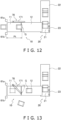
- FIG. 12 is a schematic plan view of the article conveyance unit 10 and the article alignment unit 20 in which the swinging arm 171 is disposed as the article sorting unit 70.
- the article sorting unit 70 has the swinging arm 171.
- a motor or an air cylinder is employed for the actuator that causes the swinging arm 171 to swing.
- FIG. 13 is a schematic plan view of the article conveyance unit 10 and the article alignment unit 20 when the swinging arm 171 of FIG. 12 is operating.
- the swinging arm 171 swings from a standby position ( FIG. 12 ) in which it does not interfere with the bags G on the article introduction conveyor 11 to an operative position in which it hits the bags G on the article introduction conveyor 11 and guides the bags G off the article introduction conveyor 11.
- the swinging arm 171 is also useful as the article sorting unit 70.
- Patent Document 1 JP-A No. 2018-154468
Landscapes
- Engineering & Computer Science (AREA)
- Mechanical Engineering (AREA)
- Attitude Control For Articles On Conveyors (AREA)
- Sorting Of Articles (AREA)
Abstract
It is a problem of the present disclosure to provide an article transfer apparatus in which an operation of aligning articles is not hindered even when supply intervals of the articles change. In an article transfer apparatus (1), in cases where time intervals (Pt) of bags (G) supplied from upstream to an article introduction conveyor (11) become short and a control unit (80) judges that the bags (G) will not be able to be aligned even if they reach an alignment conveyor (21), an air nozzle (71) of an article sorting unit (70) sorts the bags (G) off the article introduction conveyor (11).
Description
- The present disclosure relates to an article transfer apparatus.
- In recent years, article transfer apparatus that group together a plurality of articles and transport them to a predetermined position have become widespread. For example, Patent Document 1 (
JP-A No. 2018-154468 - In apparatus such as described above, it is necessary to perform an operation of aligning the articles on the second conveyor, and if the intervals between the articles conveyed by the first conveyed become narrow, there is the risk that there will not be enough time for the second conveyor to process the articles and that the alignment operation will be hindered, thus disturbing the orientation of the article group.
- Therefore, an article transfer apparatus is desired in which the operation of aligning the articles is not hindered even when the supply intervals of the articles change.
- An article transfer apparatus of a first aspect includes a conveyance unit, an alignment unit, a sorting unit, and a control unit. The conveyance unit conveys articles. The alignment unit collects and aligns a predetermined number of the articles conveyed thereto from the conveyance unit to form an article group. The sorting unit sorts the articles off the conveyance unit before the articles on the conveyance unit reach the alignment unit. The control unit determines whether the articles heading to the alignment unit can be aligned in the alignment unit and, when it determines that the articles cannot be aligned, sorts the articles via the sorting unit.
- In the article transfer apparatus, if the supply intervals of the articles supplied from upstream to the conveyance unit become short, there are cases where the articles may not be able to be aligned by the alignment unit even if they reach the alignment unit from the conveyance unit. In such cases, the aligned orientation of the articles becomes disturbed. Therefore, articles determined to be unable to be aligned by the alignment unit are sorted on the conveyance unit and are not allowed to reach the alignment unit, whereby disturbances in the aligned orientation of the articles are avoided beforehand.
- An article transfer apparatus of a second aspect is the article transfer apparatus of the first aspect, wherein the alignment unit includes an alignment conveyor. Each time the alignment conveyor receives one of the articles from the conveyance unit, it conveys that article a predetermined distance in one direction, stops, and waits to receive a trailing article.
- In this article transfer apparatus, some time to spare for the alignment conveyor to align the articles can be ensured without the alignment conveyor immediately delivering to the next process the articles it has received from the conveyance unit, so a situation where the next process is pressed to process the articles is inhibited.
- An article transfer apparatus of a third aspect is the article transfer apparatus of the first aspect or the second aspect, further including a first detection unit. The first detection unit detects supply intervals of the articles supplied to the conveyance unit. When the supply intervals are equal to or less than a first threshold, the control unit sorts the articles off the conveyance unit via the sorting unit.
- In this article transfer apparatus, whether to sort the articles is determined at the stage where the articles are supplied to the conveyance unit, so the articles are reliably sorted before they reach the alignment unit.
- An article transfer apparatus of a fourth aspect is the article transfer apparatus of the third aspect, further including a second detection unit. The second detection unit detects a queued number of the articles in the alignment unit. A plurality of the article groups can be aligned in the alignment unit. When the queued number of the articles becomes equal to or greater than a second threshold, the control unit sorts the articles off the conveyance unit via the sorting unit regardless of the supply intervals of the articles supplied to the conveyance unit.
- In this article transfer apparatus, even if the supply intervals of the articles supplied to the conveyance unit are appropriate, if the articles exceed an allowable level in the alignment unit there is the risk that this will disturb the alignment of the articles in the alignment unit. In such cases, the articles on the conveyance unit are sorted off the conveyance unit regardless of the supply intervals of the articles supplied to the conveyance unit, whereby hindrances to the alignment of the articles in the alignment unit are avoided.
- An article transfer apparatus of a fifth aspect is the article transfer apparatus of the fourth aspect, wherein the control unit doubles as the second detection unit. The control unit calculates the queued number of the articles based on the number of alignment operations in the alignment unit.
- In this article transfer apparatus, there is no need to provide a physical sensor, so this contributes to a reduction in apparatus cost.
- An article transfer apparatus of a sixth aspect is the article transfer apparatus of the fourth aspect, wherein the second detection unit is a camera. The control unit comprehends the queued number of the articles from an image obtained by the camera.
- An article transfer apparatus of a seventh aspect is the article transfer apparatus of any one of the first aspect to the sixth aspect, wherein the sorting unit includes an air nozzle, an air supply source, and a valve. The air nozzle jets air toward the articles. The air supply source supplies air to the air nozzle. The valve is connected between the air nozzle and the air supply source. The control unit controls the switching on and off of the valve to thereby switch between causing air to be jetted from the air nozzle and stopping air from being jetted from the air nozzle. In this article transfer apparatus, installation is easy and space is saved.
- An article transfer apparatus of an eighth aspect is the article transfer apparatus of any one of the first aspect to the sixth aspect, wherein the sorting unit has a swinging member. The swinging member swings between a standby position in which it does not interfere with the articles on the conveyance unit and an operative position in which it hits the articles on the conveyance unit and guides the articles off the conveyance unit.
- An article transfer apparatus of a ninth aspect is the article transfer apparatus of any one of the first aspect to the eighth aspect, wherein the sorting unit sorts the articles off the conveyance unit in a zone between an upstream end and a middle of the conveyance unit.
- In this article transfer apparatus, in cases where it is determined in a process upstream of the conveyance unit that the articles are rejects, the reject articles are immediately excluded.
- An article transfer apparatus of a tenth aspect is the article transfer apparatus of any one of the first aspect to the ninth aspect, further including transporting means for transporting the article group to a predetermined position. The predetermined position is movable. Even if an abnormality occurs in the movement of the predetermined position, the conveyance of the articles from the conveyance unit to the alignment unit is continued.
- In the article transfer apparatus of the present disclosure, articles determined to be unable to be aligned by the alignment unit are sorted on the conveyance unit and are not allowed to reach the alignment unit, whereby disturbances in the aligned orientation of the articles are avoided beforehand.
-
-
FIG. 1 is a schematic perspective view showing configurations of an article transfer apparatus; -
FIG. 2 is a control block diagram of the article transfer apparatus; -
FIG. 3 is a perspective view of the article transfer apparatus in which an infeed conveyor is seen from an alignment conveyor side in a state in which a surface of the infeed conveyor contacting a bag is instantaneously removed; -
FIG. 4 is a front elevation view of the orientation of a bag when the bag drops from the infeed conveyor in a case where the surface of the infeed conveyor contacting the bag is instantaneously removed; -
FIG. 5 is a front elevation view of an article transport unit; -
FIG. 6A is a schematic side view of the article transport unit collectively holding a plurality of bags; -
FIG. 6B is a schematic side view of the article transport unit transporting the plurality of bags to a container; -
FIG. 7 is a schematic plan view of an article conveyance unit and an article alignment unit; -
FIG. 8 is a schematic plan view of the article conveyance unit and the article alignment unit when an article sorting unit is operating; -
FIG. 9 is a control flowchart of the article sorting unit; -
FIG. 10 is a control flowchart of the article sorting unit of the article transfer apparatus pertaining to an example modification; -
FIG. 11 is a perspective view of the article transfer apparatus pertaining to another example modification; -
FIG. 12 is a schematic plan view of the article conveyance unit and the article alignment unit in which a swinging arm is disposed as the article sorting unit; and -
FIG. 13 is a schematic plan view of the article conveyance unit and the article alignment unit when the swinging arm ofFIG. 12 is operating. -
FIG. 1 is a schematic perspective view showing configurations of anarticle transfer apparatus 1. Referring toFIG. 1 , in a process upstream of thearticle transfer apparatus 1 in a flow of bags G, a weighing apparatus and a bagmaking and packaging machine not shown in the drawings are disposed. To thearticle transfer apparatus 1 are supplied only bags G that have passed weight, seal, and contamination inspections in the upstream process. - The
article transfer apparatus 1 is configured by anarticle conveyance unit 10, anarticle alignment unit 20, anarticle transport unit 30, anarticle detection unit 60, and anarticle sorting unit 70. Thearticle conveyance unit 10 receives the bags G and conveys them to thearticle alignment unit 20. Thearticle alignment unit 20 aligns the bags G supplied from thearticle conveyance unit 10. Thearticle transport unit 30 collectively transports to a container 40 a plurality of the bags G aligned by thearticle alignment unit 20. Thearticle sorting unit 70 sorts the bags G off thearticle conveyance unit 10 in cases where it is determined that the bags G heading to thearticle alignment unit 20 cannot be aligned in thearticle alignment unit 20. -
FIG. 2 is a control block diagram of thearticle transfer apparatus 1. Referring toFIG. 2 , acontrol unit 80 controls operations of drive parts of thearticle conveyance unit 10, thearticle alignment unit 20, thearticle transport unit 30, and thearticle sorting unit 70 of thearticle transfer apparatus 1. Thecontrol unit 80 includes aCPU 81 and aROM 82 and aRAM 83 that are connected to theCPU 81. - The
article conveyance unit 10 has anarticle introduction conveyor 11, aninfeed conveyor 12, asupport conveyor 13, and anorientation changing conveyor 14. - The
article introduction conveyor 11 receives a supply of the bags G that have passed the weight, seal, and contamination inspections and guides the bags G to theinfeed conveyor 12. - The
infeed conveyor 12 conveys the bags G conveyed thereto from thearticle introduction conveyor 11 to thearticle alignment unit 20. - Furthermore, as shown in
FIG. 1 , the conveyance surface of theinfeed conveyor 12 is inclined in a clockwise direction when its downstream side is seen from its upstream side in the conveyance direction of the bags G. - Specifically, the orientation of each of the bags G when switching from the
infeed conveyor 12 to analignment conveyor 21 is inclined in such a way that the part of the bag G that lands on the bag G already placed on thealignment conveyor 21 is up and the part of the bag G that lands directly on thealignment conveyor 21 is down. - The
infeed conveyor 12 is extensible and retractable. In the present embodiment, when the bags G reach the leading end portion of theinfeed conveyor 12, the surface of theinfeed conveyor 12 contacting the bags G is instantaneously removed.FIG. 3 is a perspective view of thearticle transfer apparatus 1 in which theinfeed conveyor 12 is seen from thealignment conveyor 21 side in a state in which the surface of theinfeed conveyor 12 contacting a bag G is instantaneously removed. Furthermore,FIG. 4 is a front elevation view of the orientation of a bag G when the bag G drops from theinfeed conveyor 12 in a case where the surface of theinfeed conveyor 12 contacting the bag G is instantaneously removed. - Referring to
FIG. 3 andFIG. 4 , when a bag G is conveyed to the downstream side of theinfeed conveyor 12 and aposition sensor 15 detects that the leading end portion of the bag G has reached the leading end portion of theinfeed conveyor 12, a leading end portion roller R1 of theinfeed conveyor 12 moves a distance D1 in a direction X2 opposite the conveyance direction (a first direction X1). At this time, an intermediate roller R2 of theinfeed conveyor 12 also moves the distance D1 in the direction X2 in conjunction therewith, thereby absorbing slack in the conveyor belt when the leading end portion roller R1 moves in the direction X2. - Because the leading end portion of the
infeed conveyor 12 instantaneously moves to the upstream side of the bag G, the bag G suddenly loses the drag from the conveyance surface of theinfeed conveyor 12 but due to inertia maintains the orientation that it had while it was being conveyed. - Therefore, the bag G easily maintains its orientation when it leaves the
infeed conveyor 12, and a disturbance in orientation when the bag G lands on thealignment conveyor 21 is inhibited. - The
support conveyor 13 is disposed on the lower end portion in the direction of inclination of theinfeed conveyor 12. The conveyance surface of thesupport conveyor 13 and the conveyance surface of theinfeed conveyor 12 are orthogonal to each other. The bags G moving on the conveyance surface of theinfeed conveyor 12 are subjected to a component of the force of gravity along the direction of inclination, so they move while sliding downward toward thesupport conveyor 13 and thereafter move along thesupport conveyor 13. The conveyance surface of thesupport conveyor 13 moves along the advancing direction of the conveyance surface of theinfeed conveyor 12 so as to not hinder the conveyance of the bags G. - The
orientation changing conveyor 14 is disposed on the upper end portion in the direction of inclination of theinfeed conveyor 12. Theorientation changing conveyor 14 is disposed in such a way as to oppose thesupport conveyor 13 on the conveyance surface of theinfeed conveyor 12. When theorientation changing conveyor 14 is seen using the conveyance surface of theinfeed conveyor 12 as a front elevation, the downstream end of theorientation changing conveyor 14 in the conveyance direction is in a position nearer to thesupport conveyor 13 than the upstream end. - When the corners of the bags G contact the
orientation changing conveyor 14, the bags G rotate in a counterclockwise direction about the point of contact and the orientation of the bags G changes so that long sides of the bags G are oriented obliquely downward along theorientation changing conveyor 14. Thereafter, the bags G hit thesupport conveyor 13, changing orientation so that the long sides of the bags G are along thesupport conveyor 13, and head to thealignment conveyor 21. - The
article alignment unit 20 has thealignment conveyor 21, anoutfeed conveyor 22, and arotation prevention conveyor 23. - The
alignment conveyor 21 and theinfeed conveyor 12 are arranged in such a way that their conveyance surfaces are orthogonal to each other. Each time thealignment conveyor 21 catches one bag G, it conveys that bag G a fixed distance toward theoutfeed conveyor 22. - Therefore, the bag G moves the fixed distance closer to the
outfeed conveyor 22 from the position where it dropped. A part of the bag G that comes dropping thereafter lands on thealignment conveyor 21 while the remaining part inclines against the preceding bag G. Therefore, the bags G on thealignment conveyor 21 form a line in such a way that mutually adjacent bags partially lie on top of each other. - After the bag G at the rear of the line lands on the
alignment conveyor 21, thealignment conveyor 21 and theoutfeed conveyor 22 simultaneously start operating, and thealignment conveyor 21 and theoutfeed conveyor 22 perform a conveyance operation in the same direction. N-number of the bags G aligned in a line on thealignment conveyor 21 move as one article group to theoutfeed conveyor 22, and the article group that was already on theoutfeed conveyor 22 further advances on theoutfeed conveyor 22. - The
rotation prevention conveyor 23 is disposed in a substantially vertical orientation so as to oppose the terminal end of theinfeed conveyor 12. Specifically, therotation prevention conveyor 23 is disposed along the side surface of thealignment conveyor 21 positioned on the far side from the terminal end of theinfeed conveyor 12 among the two side surfaces of thealignment conveyor 21. - The bags G that have lost the drag from the
infeed conveyor 12 are given a velocity component in the first direction X1 as shown inFIG. 4 , so they drop while moving closer to the side surface of thealignment conveyor 21 on the far side from the terminal end of theinfeed conveyor 12 among the two side surfaces of thealignment conveyor 21. - When the bags G land on the
alignment conveyor 21, they land in such a way that short sides of the bags G hit therotation prevention conveyor 23 and those short sides are substantially along the conveyance surface of therotation prevention conveyor 23. - The conveyance surface of the
rotation prevention conveyor 23 advances synchronously with thealignment conveyor 21 at the same speed as the conveyance surface of thealignment conveyor 21 in a second direction Y that is the conveyance direction of thealignment conveyor 21. Therefore, the short sides of the bags G contacting the conveyance surface of therotation prevention conveyor 23 and the short sides of the bags G not contacting the conveyance surface of therotation prevention conveyor 23 advance at the same speed, so rotation of the bags G is avoided. - Consequently, the
rotation prevention conveyor 23 prevents rotation of the bags G and does not just merely guide the bags G so that the short sides of the bags G are along the second direction Y - The
article transport unit 30 is a parallel link robot having three sets of links. Thearticle transport unit 30 picks up the article group of the bags G that have been conveyed thereto on theoutfeed conveyor 22 and moves in a horizontal direction to the area over acontainer 40. When thearticle transport unit 30 reaches the area over the container, it transfers the article group to the inside of thecontainer 40. -
FIG. 5 is a front elevation view of thearticle transport unit 30. Referring toFIG. 5 , thearticle transport unit 30 includes abase 32, threeservomotors parallel link arms suction holder 38. Thearticle transport unit 30 is a robot configured by these. - As shown in
FIG. 5 , thebase 32 is positioned over theoutfeed conveyor 22 or the container 40 (seeFIG. 3 ). Thebase 32 holds under it the threeservomotors - Upper ends of the
parallel link arms servomotors suction holder 38. - During operation of the
article transport unit 30, the amounts of rotation and the directions of rotation of the output shafts of theservomotors parallel link arms suction holder 38 moves to arbitrary positions in a fixed three-dimensional space. - The
suction holder 38 has a plurality ofsuction pads 38a on its lower portion. Thesuction pads 38a are connected to asuction tube 36 extending from a vacuum pump or a vacuum blower (not shown in the drawings) and switch between a state in which they suck and hold the bags G and a state in which suction is canceled. Due to the suction of the article groups by thesuction pads 38a and the cancelation of the suction, thesuction holder 38 can both grab hold of and release the article groups. - Specifically, as shown in
FIG. 5 , thesuction holder 38 collectively grabs hold of a bag G1, a bag G2, and a bag G3 on theoutfeed conveyor 22, theparallel link arms suction holder 38, and the suction by thesuction holder 38 is canceled over thecontainer 40. Because of this, the bag G1, the bag G2, and the bag G3 disengage from thesuction holder 38 and are transferred into the container. - While the bag G1, the bag G2, and the bag G3, which are a first article group, are being transported, a bag G4, a bag G5, and a bag G6, which are a subsequent second article group, are already standing by on the
alignment conveyor 21. A gap along the conveyance direction is ensured between the first article group and the second article group, so when thearticle transport unit 30 transports the first article group, the bag G4, the bag G5, and the bag G6 of the second article group are kept from being sucked by thesuction holder 38. -
FIG. 6A is a schematic side view of thearticle transport unit 30 collectively holding a plurality of bags G. Furthermore,FIG. 6B is a schematic side view of thearticle transport unit 30 transporting the plurality of bags G to acontainer 40. - Referring to
FIG. 6A and FIG. 6B , thesuction holder 38 of thearticle transport unit 30 collectively sucks the plurality of bags G in the article group moving thereto on theoutfeed conveyor 22, transports them to thecontainer 40, and transfers them into thecontainer 40. Thecontainer 40 is moved to a subsequent position by acontainer conveyor 50 each time an article group is dropped. - The
article detection unit 60 includes afirst detection unit 61 and asecond detection unit 62. Thefirst detection unit 61 detects the bags G passing over thearticle introduction conveyor 11 of thearticle conveyance unit 10. Thesecond detection unit 62 detects the quantity of the bags G waiting on thealignment conveyor 21 and theoutfeed conveyor 22. Here, thecontrol unit 80 doubles as thesecond detection unit 62. -
FIG. 7 is a schematic plan view of thearticle conveyance unit 10 and thearticle alignment unit 20. Referring toFIG. 7 , thefirst detection unit 61 is a photoelectric sensor having alight emitting unit 61a and alight receiving unit 61b. Thefirst detection unit 61 is disposed in a position in which it can detect the bags G advancing past the entrance of thearticle introduction conveyor 11. - Furthermore, as shown in
FIG. 2 , the first detection unit 61 (thelight emitting unit 61a and thelight receiving unit 61b) are connected to thecontrol unit 80. The signal voltage input to thecontrol unit 80 when thelight receiving unit 61b is receiving the light from thelight emitting unit 61a and the signal voltage input to thecontrol unit 80 when thelight receiving unit 61b is not receiving the light from thelight emitting unit 61a are different. - When the bags G pass between the
light emitting unit 61a and thelight receiving unit 61b, the light from thelight emitting unit 61a is blocked, so thelight receiving unit 61b cannot receive the light and the signal voltage input to thecontrol unit 80 changes. This allows the passage of the bags G to be detected. - Regarding the control by the
control unit 80, each time thealignment conveyor 21 catches one bag G, it conveys that bag G a fixed distance toward theoutfeed conveyor 22. Then, when an article group comprising a predetermined number of the bags G is formed on thealignment conveyor 21, thealignment conveyor 21 conveys the article group onto theoutfeed conveyor 22. - The
control unit 80 successively measures, from this series of operations, the quantity of the bags G waiting on thealignment conveyor 21 and the outfeed conveyor 22 (hereinafter called a queued number F). Here, although thecontrol unit 80 doubles as thesecond detection unit 62, thesecond detection unit 62 is not limited to this, and a sensor may be separately provided as thesecond detection unit 62. -
FIG. 8 is a schematic plan view of thearticle conveyance unit 10 and thearticle alignment unit 20 when thearticle sorting unit 70 is operating. Referring toFIG. 8 , thearticle sorting unit 70 has anair nozzle 71, anair supply source 72, and anelectromagnetic valve 73. - The
air nozzle 71 can jet air toward the bags G. Theair supply source 72 supplies air to the air nozzle. Theelectromagnetic valve 73 is connected between theair nozzle 71 and theair supply source 72. - The
control unit 80 controls the switching on and off of theelectromagnetic valve 73 to thereby switch between causing air to be jetted from theair nozzle 71 and stopping air from being jetted from theair nozzle 71. - As shown in
FIG. 7 , thecontrol unit 80 measures, based on the input signals from thefirst detection unit 61, a time interval Pt from when an Nth bag G is detected to when an N+1th bag G is detected. Furthermore, thecontrol unit 80 calculates the relative distance between the Nth bag G and the N+1th bag G based on the conveyance speeds of thearticle introduction conveyor 11 and theinfeed conveyor 12 and the time interval Pt. - Consequently, the shorter the time interval Pt is, the shorter the relative distance between the Nth bag G and the N+1th bag G is. If the relative distance between the Nth bag G and the N+1th bag G is too short, there is the risk that the N+1th bag G will reach the
alignment conveyor 21 before the Nth bag G is completely aligned on thealignment conveyor 21 and disturb the alignment of the bags G. - Thus, in the present embodiment, when the time interval Pt is equal to or less than a first threshold SH1, it is judged that the trailing N+1th bag G is too close to the preceding Nth bag G and that the alignment of the Nth bag G on the
alignment conveyor 21 will be hindered. - Therefore, before the N+1th bag G on the
article introduction conveyor 11 moves to theinfeed conveyor 12, thecontrol unit 80 causes air to be jetted from theair nozzle 71 toward the N+1th bag G to thereby sort the N+1th bag G off thearticle introduction conveyor 11. - As shown in
FIG. 8 , theair nozzle 71 can sort the bags G off thearticle conveyance unit 10 in the zone of thearticle introduction conveyor 11. Therefore, reject articles are immediately excluded not only in cases where the alignment of a preceding bag G will be hindered but also in cases where the bags G are determined to be rejects in the process upstream of thearticle introduction conveyor 11. - Here, operations will be described supposing a state in which the bag G1, the bag G2, and the bag G3 that have passed the inspections have been introduced from upstream at appropriate supply intervals to the
article introduction conveyor 11 and are being sequentially supplied to theinfeed conveyor 12. Consequently, the operation of thearticle sorting unit 70 will not be described here but will be described further below. - The
infeed conveyor 12 conveys toward thealignment conveyor 21 the bag G1 supplied from thearticle introduction conveyor 11. When the leading end portion of the bag G1 reaches the leading end portion of theinfeed conveyor 12, the leading end portion of theinfeed conveyor 12 instantaneously moves the distance D1 in the direction X2 opposite the first direction X1 as shown inFIG. 4 . - The bag G1 lands on the
alignment conveyor 21 while maintaining the orientation it had just before the surface of theinfeed conveyor 12 contacting the bag G1 was removed. When there is no preceding bag on thealignment conveyor 21, the bag G1 becomes the front of the line on thealignment conveyor 21. For convenience of description, the bag G1 will be described as the front of the line. - When the
alignment conveyor 21 catches the bag G1, it conveys the bag G1 the fixed distance toward theoutfeed conveyor 22 and waits to receive the trailing bag G2. - Next, when the leading end portion of the bag G2 reaches the leading end portion of the
infeed conveyor 12, the surface of theinfeed conveyor 12 contacting the bag G2 is instantaneously removed and the bag G2 also lands on thealignment conveyor 21 while maintaining the orientation it has at that time. - The
infeed conveyor 12 is inclined in such a way that the part of the bag G2 that lands on the bag G1 already placed on thealignment conveyor 21 is up and the part of the bag G2 that lands directly on thealignment conveyor 21 is down, so the bag G2 drops while maintaining its inclined orientation, a part of the bag G2 lands on the bag G1, and the remaining part of the bag G2 lands on thealignment conveyor 21. - When the
alignment conveyor 21 catches the bag G2, it conveys the bag G1 and the bag G2 the fixed distance toward theoutfeed conveyor 22 and waits to receive the trailing bag G3. - Next, when the leading end portion of the bag G3 reaches the leading end portion of the
infeed conveyor 12, the surface of theinfeed conveyor 12 contacting the bag G3 is instantaneously removed and the bag G3 also lands on thealignment conveyor 21 while maintaining the orientation it has at that time. A part of the bag G3 lands on the bag G2 while the remaining part lands on thealignment conveyor 21. - The bag G1, the bag G2, and the bag G3 on the
alignment conveyor 21 form a line in which mutually adjacent bags partially lie on top of each other. When the line of the bag G1, the bag G2, and the bag G3 is finished, thealignment conveyor 21 conveys the line as one article group to theoutfeed conveyor 22. At this time, theoutfeed conveyor 22 also operates in the same direction, so the article group on thealignment conveyor 21 moves onto theoutfeed conveyor 22. If there is a preceding article group on theoutfeed conveyor 22, that article group moves further downstream. - As shown in
FIG. 6A and FIG. 6B , thesuction holder 38 of thearticle transport unit 30 collectively sucks the plurality of bags G in the article group moving thereto on theoutfeed conveyor 22, transports them to thecontainer 40, and transfers them into thecontainer 40. Thecontainer 40 is moved to a subsequent position by thecontainer conveyor 50 each time an article group is dropped. - The
article transfer apparatus 1 repeats the above operations to pack the necessary bags G in thecontainer 40. - Furthermore, even if an abnormality occurs in the movement of the
container 40 by thecontainer conveyor 50, the conveyance of the bags G from thearticle conveyance unit 10 to thearticle alignment unit 20 is continued. - Here, the operation of the
article sorting unit 70 will be describing supposing a case where the supply intervals of the bags G supplied to thearticle introduction conveyor 11 are not stable.FIG. 9 is a control flowchart of thearticle sorting unit 70. - In step S1 of
FIG. 9 , thecontrol unit 80 resets a counter to N = 1. - In step S2, the
control unit 80 starts keeping time. - In step S3, the
control unit 80 determines whether there is a bag detection signal indicating that a bag G has been detected. Thecontrol unit 80 proceeds to step S4 when there is a bag detection signal and continues determining whether there is a bag detection signal when there is not a bag detection signal. - In step S4, the
control unit 80 stores the time when the bag G was detected in step S3 as a time t(N) when the Nth bag G was detected. - In step S5, the
control unit 80 determines whether there is a bag detection signal indicating that a bag G has been detected. Thecontrol unit 80 proceeds to step S6 when there is a bag detection signal and continues determining whether there is a bag detection signal when there is not a bag detection signal. - In step S6, the
control unit 80 adds 1 to the counter. - In step S7, the
control unit 80 stores the time when the bag G was detected in step S5 as a time t(N+1) when the N+1th bag G was detected. - In step S8, the
control unit 80 calculates the time interval Pt = t(N+1) - t(N). - In step S9, the
control unit 80 determines whether the time interval Pt is equal to or less than the first threshold SH1. When Pt ≤ SH1, the N+1th bag G is too close to the Nth bag G. Therefore, there is the risk that as the Nth bag G is being aligned on thealignment conveyor 21 the N+1th bag G will reach thealignment conveyor 21 and hinder the alignment of the Nth bag G. - When Pt ≤ SH1, the
control unit 80 proceeds to step S10 and needs to exclude the N+1th bag G before it reaches thealignment conveyor 21. When Pt is not ≤ SH1, thecontrol unit 80 returns to step S5. - In step S10, the
control unit 80 opens theelectromagnetic valve 73 of thearticle sorting unit 70 to jet air from thenozzle 71 toward the N+1th bag G on thearticle introduction conveyor 11. Because of this, the N+1th bag G is sorted off thearticle introduction conveyor 11. - In step S11, the
control unit 80 determines whether there is a signal to stop thearticle transfer apparatus 1. Thecontrol unit 80 ends the control when there is a stop signal and returns to step S5 when there is not a stop signal. - As described above, in the present embodiment, in cases where the supply intervals of the bags G supplied to the
article introduction conveyor 11 are unstable and there is the risk that the intervals between the bags G are narrow and will hinder the alignment of the bags G, thearticle sorting unit 70 can exclude the bags G that risk hindering alignment. -
FIG. 10 is a control flowchart of thearticle sorting unit 70 of thearticle transfer apparatus 1 pertaining to an example modification. What is different from the control flowchart ofFIG. 9 is that step S9 is changed to step S9A and a new step S9B is added. - Referring to
FIG. 10 , steps S1 to S8, S10, and S11 are the same as those in the above embodiment, so description thereof is omitted. - In step S9A, the
control unit 80 determines whether the time interval Pt is equal to or less than the first threshold SH1. When Pt ≤ SH1, the N+1th bag G is too close to the Nth bag G. Therefore, there is the risk that as the Nth bag G is being aligned on thealignment conveyor 21 the N+1th bag G will reach thealignment conveyor 21 and hinder the alignment of the Nth bag G. - Therefore, when Pt ≤ SH1, the
control unit 80 proceeds to step S10 and needs to exclude the N+1th bag G before it reaches thealignment conveyor 21. When Pt is not ≤ SH1, thecontrol unit 80 proceeds to step S9B. - In step S9B, the
control unit 80 determines whether the queued number F, which is the quantity of the bags G waiting on thealignment conveyor 21 and theoutfeed conveyor 22, is equal to or greater than a second threshold SH2. When F ≥ SH2, even if the interval between the N+1th bag G and the Nth bag G is proper, the bags G are stalled on thealignment conveyor 21 and theoutfeed conveyor 22, so it is best not to convey the bags G to thealignment conveyor 21. - Therefore, when F ≥ SH2, the
control unit 80 proceeds to step S10 and needs to exclude the N+1th bag G before it reaches thealignment conveyor 21. When F is not ≥ SH2, thecontrol unit 80 returns to step S5. - As described above, in the present example modification, even if the supply intervals of the bags G supplied to the
article introduction conveyor 11 are stable, in cases where there is the risk that the bags G are stalled on thealignment conveyor 21 and theoutfeed conveyor 22 and the alignment of the bags G will be hindered, thearticle sorting unit 70 excludes the bags G that risk hindering alignment. - In the
article transfer apparatus 1, in cases where the time intervals Pt of the bags G supplied from upstream to thearticle introduction conveyor 11 become short and thecontrol unit 80 judges that the bags G will not be able to be aligned even if they reach thealignment conveyor 21, theair nozzle 71 of thearticle sorting unit 70 sorts the bags G off thearticle introduction conveyor 11. - Each time the
alignment conveyor 21 receives one of the bags G from theinfeed conveyor 12, it conveys that bag G a predetermined distance in one direction, stops, and waits to receive a trailing bag G. Some time to spare for thealignment conveyor 21 to align the bags G can be ensured without thealignment conveyor 21 immediately delivering to the next process the bags G it has received from theinfeed conveyor 12, so a situation where the next process is pressed to process the bags G is inhibited. - The
control unit 80 measures via thefirst detection unit 61 the time intervals Pt that are supply intervals of the bags G supplied to thearticle introduction conveyor 11. When the time intervals Pt are equal to or less than the first threshold SH1, thecontrol unit 80 sorts the bags G off thearticle introduction conveyor 11 via thearticle sorting unit 70. Whether to sort the bags G is determined at the stage where the bags G are supplied to thearticle introduction conveyor 11, so the bags G are reliably sorted before they reach thealignment conveyor 21. - The
second detection unit 62 detects the queued number of the bags G on thealignment conveyor 21 and theoutfeed conveyor 22. When the queued number of the bags G is equal to or greater than the second threshold SH2, thecontrol unit 80 sorts the bags G off thearticle introduction conveyor 11 via thearticle sorting unit 70 regardless of the time intervals Pt. - Even if the time intervals Pt that are supply intervals of the bags G supplied to the
article introduction conveyor 11 are appropriate, if the queued number F of the bags G on thealignment conveyor 21 and theoutfeed conveyor 22 exceeds an allowable level there is the risk that this will disturb the alignment of the bags G on thealignment conveyor 21 and theoutfeed conveyor 22. In such cases, the bags G are sorted off thearticle introduction conveyor 11 regardless of the supply intervals of the bags G supplied to thearticle introduction conveyor 11, whereby hindrances to the alignment of the bags G on thealignment conveyor 21 are avoided. - The
control unit 80 doubles as thesecond detection unit 62. Thecontrol unit 80 calculates the queued number F of the articles based on the number of alignment operations in thealignment conveyor 21 and theoutfeed conveyor 22. - The
article sorting unit 70 includes theair nozzle 71, theair supply source 72, and theelectromagnetic valve 73. Thecontrol unit 80 controls the switching on and off of theelectromagnetic valve 73 to thereby switch between causing air to be jetted from theair nozzle 71 and stopping air from being jetted from theair nozzle 71. - The
air nozzle 71 can sort the bags G off thearticle conveyance unit 10 in the zone of thearticle introduction conveyor 11. In cases where it is determined in a process upstream of thearticle introduction conveyor 11 that the bags G are rejects, the reject articles are immediately excluded. - Even if an abnormality occurs in the movement of the
container 40, the conveyance of the bags G from thearticle conveyance unit 10 to thearticle alignment unit 20 is continued. - In the above embodiment, the
control unit 80 doubles as thesecond detection unit 62 and theair nozzle 71 is employed for thearticle sorting unit 70. However, the disclosure is not limited to this, and thesecond detection unit 62 may be a camera. Furthermore, thearticle sorting unit 70 may be a swinging arm that swings between a standby position and an operative position. -
FIG. 11 is a perspective view of thearticle transfer apparatus 1 pertaining to another example modification. Referring toFIG. 11 , acamera 162 is employed as thesecond detection unit 62, and a swingingarm 171 is employed as thearticle sorting unit 70. - The
control unit 80 comprehends the queued number F of the bags G on thealignment conveyor 21 and theoutfeed conveyor 22 from an image obtained by thecamera 162. - In step S9B of
FIG. 10 , thecontrol unit 80 determines whether the queued number F is equal to or greater than the second threshold SH2. When F ≥ SH2, even if the interval between the N+1th bag G and the Nth bag G is proper, the bags G are stalled on thealignment conveyor 21 and theoutfeed conveyor 22, so it is best not to convey the bags G to thealignment conveyor 21. - Therefore, when F ≥ SH2, the
control unit 80 proceeds to step S10 ofFIG. 10 and needs to exclude the N+1th bag G before it reaches thealignment conveyor 21. When F is not ≥ SH2, thecontrol unit 80 returns to step S5 ofFIG. 10 . - As described above, the
camera 162 is also useful as thesecond detection unit 62. -
FIG. 12 is a schematic plan view of thearticle conveyance unit 10 and thearticle alignment unit 20 in which the swingingarm 171 is disposed as thearticle sorting unit 70. Referring toFIG. 12 , thearticle sorting unit 70 has the swingingarm 171. For the actuator that causes the swingingarm 171 to swing, a motor or an air cylinder is employed. -
FIG. 13 is a schematic plan view of thearticle conveyance unit 10 and thearticle alignment unit 20 when the swingingarm 171 ofFIG. 12 is operating. Referring toFIG. 13 , the swingingarm 171 swings from a standby position (FIG. 12 ) in which it does not interfere with the bags G on thearticle introduction conveyor 11 to an operative position in which it hits the bags G on thearticle introduction conveyor 11 and guides the bags G off thearticle introduction conveyor 11. - As described above, the swinging
arm 171 is also useful as thearticle sorting unit 70. -
- 1
- Article Transfer Apparatus
- 10
- Article Conveyance Unit (Conveyance Unit)
- 11
- Article Introduction Conveyor (Conveyance Unit)
- 12
- Infeed Conveyor (Conveyance Unit)
- 20
- Article Alignment Unit (Alignment Unit)
- 21
- Alignment Conveyor (Alignment Unit)
- 30
- Article Transport Unit (Transporting Means)
- 40
- Container (Predetermined Position)
- 61
- First Detection Unit
- 62
- Second Detection Unit
- 70
- Article Sorting Unit (Sorting Unit)
- 71
- Air Nozzle
- 72
- Air Supply Source
- 73
- Electromagnetic Valve (Valve)
- 80
- Control Unit
- 162
- Camera (Second Detection Unit)
- 171
- Swinging Arm (Swinging Member)
- G
- Bags
- G1, G2, G3
- First Article Group (Article Group)
- G4, G5, G6
- Second Article Group (Article Group)
- Patent Document 1:
JP-A No. 2018-154468
Claims (10)
- An article transfer apparatus comprising:a conveyance unit that conveys articles;an alignment unit that collects and aligns a predetermined number of the articles conveyed thereto from the conveyance unit to form an article group;a sorting unit that sorts the articles off the conveyance unit before the articles on the conveyance unit reach the alignment unit; anda control unit that determines whether the articles heading to the alignment unit can be aligned in the alignment unit and, when it determines that the articles cannot be aligned, sorts the articles via the sorting unit.
- The article transfer apparatus of claim 1, wherein the alignment unit includes an alignment conveyor which, each time it receives one of the articles from the conveyance unit, conveys that article a predetermined distance in one direction, stops, and waits to receive a trailing article.
- The article transfer apparatus of claim 1 or claim 2, further comprising a first detection unit that detects supply intervals of the articles supplied to the conveyance unit, wherein when the supply intervals are equal to or less than a first threshold, the control unit sorts the articles off the conveyance unit via the sorting unit.
- The article transfer apparatus of claim 3, further comprising a second detection unit that detects a queued number of the articles in the alignment unit, whereina plurality of the article groups can be aligned in the alignment unit, andwhen the queued number of the articles becomes equal to or greater than a second threshold, the control unit sorts the articles off the conveyance unit via the sorting unit regardless of the supply intervals of the articles supplied to the conveyance unit.
- The article transfer apparatus of claim 4, whereinthe control unit doubles as the second detection unit, andthe control unit calculates the queued number of the articles based on the number of alignment operations in the alignment unit.
- The article transfer apparatus of claim 4, whereinthe second detection unit is a camera, andthe control unit comprehends the queued number of the articles from an image obtained by the camera.
- The article transfer apparatus of any one of claims 1 to 6, whereinthe sorting unit includes an air nozzle that jets air toward the articles, an air supply source that supplies air to the air nozzle, and a valve that is connected between the air nozzle and the air supply source, andthe control unit controls the switching on and off of the valve to thereby switch between causing air to be jetted from the air nozzle and stopping air from being jetted from the air nozzle.
- The article transfer apparatus of any one of claims 1 to 6, wherein the sorting unit has a swinging member that swings between a standby position in which it does not interfere with the articles on the conveyance unit and an operative position in which it hits the articles on the conveyance unit and guides the articles off the conveyance unit.
- The article transfer apparatus of any one of claims 1 to 8, wherein the sorting unit sorts the articles off the conveyance unit in a zone between an upstream end and a middle of the conveyance unit.
- The article transfer apparatus of any one of claims 1 to 9, further comprising transporting means for transporting the article group to a predetermined position, whereinthe predetermined position is movable, andeven if an abnormality occurs in the movement of the predetermined position, the conveyance of the articles from the conveyance unit to the alignment unit is continued.
Applications Claiming Priority (1)
| Application Number | Priority Date | Filing Date | Title |
|---|---|---|---|
| JP2023108274A JP2025007098A (en) | 2023-06-30 | 2023-06-30 | Item transfer device |
Publications (1)
| Publication Number | Publication Date |
|---|---|
| EP4484339A1 true EP4484339A1 (en) | 2025-01-01 |
Family
ID=91376535
Family Applications (1)
| Application Number | Title | Priority Date | Filing Date |
|---|---|---|---|
| EP24180015.0A Pending EP4484339A1 (en) | 2023-06-30 | 2024-06-04 | Article transfer apparatus |
Country Status (3)
| Country | Link |
|---|---|
| US (1) | US20250002264A1 (en) |
| EP (1) | EP4484339A1 (en) |
| JP (1) | JP2025007098A (en) |
Citations (4)
| Publication number | Priority date | Publication date | Assignee | Title |
|---|---|---|---|---|
| DE102007028680A1 (en) * | 2007-06-21 | 2008-12-24 | Elau Elektronik-Automations-Ag | Goods e.g. soft cheese, grouping station for packaging machine, has goods pick-up unit movable position-synchronously to conveyor belt, where unit is positioned on goods and brought at preselectable distance to previously moved goods |
| JP2018154468A (en) | 2017-03-17 | 2018-10-04 | 株式会社イシダ | Article alignment device |
| CN112978214A (en) * | 2020-02-10 | 2021-06-18 | 伟博泰有限公司 | Belt conveyor with ejector |
| DE102021129997A1 (en) * | 2021-11-17 | 2023-05-17 | HTI Automation GmbH | separation device |
-
2023
- 2023-06-30 JP JP2023108274A patent/JP2025007098A/en active Pending
-
2024
- 2024-06-03 US US18/732,493 patent/US20250002264A1/en active Pending
- 2024-06-04 EP EP24180015.0A patent/EP4484339A1/en active Pending
Patent Citations (4)
| Publication number | Priority date | Publication date | Assignee | Title |
|---|---|---|---|---|
| DE102007028680A1 (en) * | 2007-06-21 | 2008-12-24 | Elau Elektronik-Automations-Ag | Goods e.g. soft cheese, grouping station for packaging machine, has goods pick-up unit movable position-synchronously to conveyor belt, where unit is positioned on goods and brought at preselectable distance to previously moved goods |
| JP2018154468A (en) | 2017-03-17 | 2018-10-04 | 株式会社イシダ | Article alignment device |
| CN112978214A (en) * | 2020-02-10 | 2021-06-18 | 伟博泰有限公司 | Belt conveyor with ejector |
| DE102021129997A1 (en) * | 2021-11-17 | 2023-05-17 | HTI Automation GmbH | separation device |
Also Published As
| Publication number | Publication date |
|---|---|
| US20250002264A1 (en) | 2025-01-02 |
| JP2025007098A (en) | 2025-01-17 |
Similar Documents
| Publication | Publication Date | Title |
|---|---|---|
| US4527792A (en) | Apparatus for changing the direction of motion of letters and similar rectangular pieces of mail | |
| US7275633B2 (en) | Device for changing the direction of conveyance of flat postal items and the position of the postal items relative to their direction of conveyance | |
| JP5711011B2 (en) | Article sorting device | |
| CN113286754B (en) | Item Handling Equipment | |
| AU2007209736B2 (en) | Apparatus for collating flat objects and for conveying the collated objects further | |
| EP3971117A1 (en) | Systems, devices, and methods for extendable conveyors | |
| US10689215B2 (en) | Automatic cloth feeder | |
| JP2020125208A (en) | Article accumulation device | |
| US20100107571A1 (en) | Device for handling diapers | |
| JP6353625B2 (en) | Article handling equipment | |
| EP4477584A1 (en) | Article transfer apparatus | |
| KR20220048940A (en) | Article transport facility | |
| US20250002264A1 (en) | Article-transfer apparatus | |
| JP6038624B2 (en) | Weight sorter | |
| JP2018177539A (en) | Article supply method | |
| CN116897132A (en) | Conveyor belts for transporting materials and packaging systems including such conveyor belts | |
| WO2024118928A1 (en) | Apparatus for transferring products supplied via a first conveying apparatus to a second conveying apparatus | |
| CN114313902A (en) | Automatic part supply device | |
| JP2579006Y2 (en) | Crop sorting equipment | |
| EP4493332B1 (en) | System and method for the processing of products | |
| KR20220054296A (en) | branch facility | |
| KR20120087075A (en) | Tray Holding and Carrying Out Apparatus | |
| JP2025514061A (en) | Equipment and methods for packaging products | |
| US7083374B2 (en) | Gripping members gripping and moving packets stacked by a conveyor | |
| CN110899141B (en) | A pneumatic weighing and defective product rejection machine |
Legal Events
| Date | Code | Title | Description |
|---|---|---|---|
| PUAI | Public reference made under article 153(3) epc to a published international application that has entered the european phase |
Free format text: ORIGINAL CODE: 0009012 |
|
| STAA | Information on the status of an ep patent application or granted ep patent |
Free format text: STATUS: REQUEST FOR EXAMINATION WAS MADE |
|
| 17P | Request for examination filed |
Effective date: 20240604 |
|
| AK | Designated contracting states |
Kind code of ref document: A1 Designated state(s): AL AT BE BG CH CY CZ DE DK EE ES FI FR GB GR HR HU IE IS IT LI LT LU LV MC ME MK MT NL NO PL PT RO RS SE SI SK SM TR |