EP4484322A1 - Flip-top cap and container with which said cap is associated - Google Patents
Flip-top cap and container with which said cap is associated Download PDFInfo
- Publication number
- EP4484322A1 EP4484322A1 EP24185112.0A EP24185112A EP4484322A1 EP 4484322 A1 EP4484322 A1 EP 4484322A1 EP 24185112 A EP24185112 A EP 24185112A EP 4484322 A1 EP4484322 A1 EP 4484322A1
- Authority
- EP
- European Patent Office
- Prior art keywords
- cap
- closing element
- top closing
- tubular body
- container
- Prior art date
- Legal status (The legal status is an assumption and is not a legal conclusion. Google has not performed a legal analysis and makes no representation as to the accuracy of the status listed.)
- Granted
Links
Images



Classifications
-
- B—PERFORMING OPERATIONS; TRANSPORTING
- B65—CONVEYING; PACKING; STORING; HANDLING THIN OR FILAMENTARY MATERIAL
- B65D—CONTAINERS FOR STORAGE OR TRANSPORT OF ARTICLES OR MATERIALS, e.g. BAGS, BARRELS, BOTTLES, BOXES, CANS, CARTONS, CRATES, DRUMS, JARS, TANKS, HOPPERS, FORWARDING CONTAINERS; ACCESSORIES, CLOSURES, OR FITTINGS THEREFOR; PACKAGING ELEMENTS; PACKAGES
- B65D47/00—Closures with filling and discharging, or with discharging, devices
- B65D47/04—Closures with discharging devices other than pumps
- B65D47/06—Closures with discharging devices other than pumps with pouring spouts or tubes; with discharge nozzles or passages
- B65D47/08—Closures with discharging devices other than pumps with pouring spouts or tubes; with discharge nozzles or passages having articulated or hinged closures
- B65D47/0804—Closures with discharging devices other than pumps with pouring spouts or tubes; with discharge nozzles or passages having articulated or hinged closures integrally formed with the base element provided with the spout or discharge passage
-
- B—PERFORMING OPERATIONS; TRANSPORTING
- B65—CONVEYING; PACKING; STORING; HANDLING THIN OR FILAMENTARY MATERIAL
- B65D—CONTAINERS FOR STORAGE OR TRANSPORT OF ARTICLES OR MATERIALS, e.g. BAGS, BARRELS, BOTTLES, BOXES, CANS, CARTONS, CRATES, DRUMS, JARS, TANKS, HOPPERS, FORWARDING CONTAINERS; ACCESSORIES, CLOSURES, OR FITTINGS THEREFOR; PACKAGING ELEMENTS; PACKAGES
- B65D2251/00—Details relating to container closures
- B65D2251/10—Details of hinged closures
- B65D2251/1008—Means for locking the closure in open position
Definitions
- the present invention concerns the field of plastic caps, and in particular the field of flip-top caps, which can be opened easily, for example with a movement of the thumb.
- a flip-top cap is attached to the dispenser mouth of a thin-walled flexible container, preferably suitable for holding toilet cleaners.
- Flip-top caps consist of a dispenser tubular body applied to the upper end of a container and in turn provided with a dispenser mouth.
- This cap is also provided with a top closing element made as a single body with the dispenser tubular body, which alternately determines the open and closed conditions of the dispenser tubular body itself.
- the top closing element is joined to the dispenser tubular body by flexible hinge means called, in fact, hinge; the hinge is such that it allows the top closing element and the dispenser tubular body to move with respect to each other during the opening and closing steps of the container.
- the top closing element protects the dispenser mouth of the dispenser tubular body, through which the liquid flows out of the container, from contact with foreign bodies, and ensures the necessary hygiene. Moreover, advantageously, with said caps it is not necessary to pay attention to the above-mentioned top closing element during the opening step, as it remains integral with the dispenser tubular body and there is no risk of losing it and of dirtying it if it is accidentally dropped.
- the containers associated with these types of caps are used to hold shampoos, body washes or dishwashing detergents.
- flip-top caps are configured to dispense the contents of the container in a direction that is essentially parallel to the extension axis of the container itself.
- the first reason is related to the fact that, with the dispenser mouth in a direction substantially parallel to the extension of the container, it is difficult to reach the above-mentioned rim.
- the second reason is related to the fact that the above-mentioned top closing element itself, once opened, becomes an obstacle when approaching said rim or any area of any object having no direct access.
- the first is related to the fact that the cap that closes said latter containers is a separate item, with the disadvantage that it can be lost or can accidentally fall on the ground and become contaminated.
- the second is related to the fact that said containers in the above-mentioned particular shape are, from an industrial point of view, much more complex to fill with the appropriate liquid product compared to containers whose dispenser mouth is substantially parallel to the extension axis of the container itself, and therefore pointing upwards during filling, and which are subsequently coupled with a flip-top cap.
- the task of the present invention is to develop a flip-top cap that overcomes the drawbacks of the caps of the known type.
- the container to which the cap according to the invention is associated is also part of the invention.
- the flip-top cap according to the invention which can be associated with thin-walled flexible containers, is shown in Figures from 1 to 6, where it is indicated as a whole by 1 .
- Said cap 1 comprises a tubular body 2 in which, at a first end 2a lying on a first plane ⁇ 1 , coupling means 3 are defined for coupling the same cap 1 and a container 100 together.
- the cap 1 is provided with a dispenser tube 4 , visible in Figures from 4 to 6, comprising a tubular wall 41 that defines a dispenser mouth 5 of the cap 1 according to a main axis X1 , through which the contents of the container 100 are dispensed.
- a dispenser tube 4 visible in Figures from 4 to 6, comprising a tubular wall 41 that defines a dispenser mouth 5 of the cap 1 according to a main axis X1 , through which the contents of the container 100 are dispensed.
- the dispenser tube 4 extends projecting from a surface 6 defined at the second end 2b of the tubular body 2 , so that the main axis X1 is substantially orthogonal to the surface 6.
- the cap 1 comprises a top closing element 7 hinged to the tubular body 2 through hinge means 8 , so as to allow the top closing element 7 to rotate around a hinge axis Y1 orthogonal to the main axis X1 .
- the top closing element 7 is suited to close the dispenser mouth 5 of the dispenser tube 4.
- the surface 6 lies on a second plane ⁇ 2 incident on the first plane ⁇ 1 , as can be seen in Figures 1 , 3 , 4 and 6 , so that the main axis X1 is oblique with respect to the first plane ⁇ 1 .
- the top closing element 7 is hinged to the tubular body 2 at a first section 9 of the second end 2b of the tubular body 2 itself, facing towards the line of incidence r between the first plane ⁇ 1 and said second plane ⁇ 2 .
- the combination of features described above has the advantage of making it possible to provide a flip-top cap that can be applied to the same containers to which the known flip-top caps are applied, and at the same time makes it possible to define a dispensing direction of the contents of such containers that is oblique with respect to the extension axis of the containers themselves. This makes it possible to easily fill containers at the industrial stage, while at the same time allowing the container with the associated cap 1 of the invention to be used to apply said contents to areas without direct access, such as for example the rim of a toilet.
- top closing element 7 is hinged to the tubular body 2 at said first section 9 allows the same top closing element 7 , when the cap 1 is open, not to hinder the approaching movement of the dispenser mouth 5 , for example, to the rim B of a toilet, as schematically shown in Figure 7 .
- the top closing element 7 is configured to rotate around the hinge axis Y1 from a closed position, in which the top closing element 7 itself closes the dispenser mouth 5 , to a completely open position, according to which the bottom 7a of said top closing element 7 is substantially coplanar with the surface 6 .
- said last detail feature provides a better guarantee that the top closing element 7 is not an obstacle to the approaching movement of the dispenser mouth 5 towards the rim of a toilet, for example.
- the cap 1 is also provided with first locking means 11 , at the portion 10 of the side wall 2c of the tubular body 2 facing towards the line of incidence r, and with second locking means 12 , complementary to the first locking means 11 , at the outer wall 7b of the top closing element 7 facing the portion 10 of the side wall 2c , when the top closing element 7 is in the completely open position.
- the first locking means 11 and the second locking means 12 are configured to be reversibly coupled together and keep the top closing element 7 locked in the completely open position. This makes it possible to keep the top closing element 7 in the completely open position when applying the contents of the container at the level of the rim of a toilet, for example, thus preventing the top closing element 7 from moving and hindering said application.
- the first locking means 11 comprise a locking tooth 13 projecting from the portion 10 of the side wall 2c and the second locking means 12 comprise a locking opening 14 in which the locking tooth 13 is suited to become engaged by interference, when the top closing element 7 is in the completely open position.
- the dispenser tube 4 has substantially the shape of a truncated cone, as can be observed in Figure 4 .
- the top closing element 7 is substantially in the shape of a scalene trapezoid 15 , in which the lower portion 16 of the longer oblique side 15a is hinged to the tubular body 2 .
- Said characteristic advantageously makes it easier to ensure the coplanarity of the bottom 7a of the top closing element 7 with respect to the surface 6 , when the top closing element 7 itself is in the completely open position, as shown in Figure 4 .
- the cap 1 is configured so that the tubular body 2 comprises first coupling means 18 at a second section 17 of the second end 2b , diametrically opposite the hinge means 8 . Furthermore, it is provided that the top closing element 7 , at its portion facing the first coupling means 18 , when it is in said closed position, comprises second coupling means 19 , complementary to the first coupling means 18 , so that said first coupling means 18 are reversibly engaged with the second coupling means 19 , as shown in Figure 2 .
- This advantageously, makes it possible to keep the cap 1 closed in a stable manner and to prevent the cap itself from opening accidentally.
- a thin-walled flexible container 100 shown in Figure 8 and preferably suitable for holding toilet cleaners, is also part of the invention.
- Said container has a substantially longitudinal extension along an extension axis X3.
- said container 100 comprises a cap 1 of the invention coupled thereto at its dispenser mouth 101.
- the dispenser mouth 101 of the container 100 is defined on a surface 102 substantially parallel to the bottom 103 of the container itself and perpendicular to the extension axis X3. In this way, the container 100 remains easy to be filled at an industrial level.
- the cap 1 of the invention is coupled with the container 100 through coupling means 3 at the level of said surface 102 , so that the main axis X1 of the same cap 1 is oblique with respect to the bottom 103 and the longitudinal axis X3 .
- the object to provide a flip-top cap suited to be applied to containers whose dispenser mouth is parallel to the extension axis of the container and, at the same time, which are suited to be used for the application, for example, of toilet detergents or other detergents at the level of the rim of a toilet or at any other area without direct access is achieved.
- the object to provide a flip-top cap which makes such particular uses possible and which, at the same time, can be associated with containers that are easier to fill industrially than the containers specifically made for such uses is achieved.
Landscapes
- Engineering & Computer Science (AREA)
- Mechanical Engineering (AREA)
- Closures For Containers (AREA)
Abstract
Description
- The present invention concerns the field of plastic caps, and in particular the field of flip-top caps, which can be opened easily, for example with a movement of the thumb.
- According to the present invention, in particular, a flip-top cap is attached to the dispenser mouth of a thin-walled flexible container, preferably suitable for holding toilet cleaners.
- Flip-top caps are known which consist of a dispenser tubular body applied to the upper end of a container and in turn provided with a dispenser mouth.
- This cap is also provided with a top closing element made as a single body with the dispenser tubular body, which alternately determines the open and closed conditions of the dispenser tubular body itself. In particular, the top closing element is joined to the dispenser tubular body by flexible hinge means called, in fact, hinge; the hinge is such that it allows the top closing element and the dispenser tubular body to move with respect to each other during the opening and closing steps of the container.
- Advantageously, the top closing element protects the dispenser mouth of the dispenser tubular body, through which the liquid flows out of the container, from contact with foreign bodies, and ensures the necessary hygiene. Moreover, advantageously, with said caps it is not necessary to pay attention to the above-mentioned top closing element during the opening step, as it remains integral with the dispenser tubular body and there is no risk of losing it and of dirtying it if it is accidentally dropped.
- Usually, the containers associated with these types of caps are used to hold shampoos, body washes or dishwashing detergents.
- However, despite the said advantages, flip-top caps are configured to dispense the contents of the container in a direction that is essentially parallel to the extension axis of the container itself.
- This, consequently, leads to the technical disadvantage that the containers to which said flip-top caps are attached are not suitable to be used for particular purposes or in particular circumstances, above all when the container is intended to be used to apply a toilet cleaner to the rim of the toilet, that is, to its inner upper edge, under which the flush water usually runs.
- In fact, said containers with flip-top caps are not suitable for the use described above for basically two reasons.
- The first reason is related to the fact that, with the dispenser mouth in a direction substantially parallel to the extension of the container, it is difficult to reach the above-mentioned rim.
- The second reason is related to the fact that the above-mentioned top closing element itself, once opened, becomes an obstacle when approaching said rim or any area of any object having no direct access.
- In fact, it is known that there are specific containers made for these special uses, having an integrated dispensing spout whose dispenser mouth is oblique with respect to the extension axis of the container, so as to facilitate the approach of said dispenser mouth to the particular areas to be treated such as, for example, the toilet rim.
- However, even this type of containers has two major disadvantages.
- The first is related to the fact that the cap that closes said latter containers is a separate item, with the disadvantage that it can be lost or can accidentally fall on the ground and become contaminated.
- The second, instead, is related to the fact that said containers in the above-mentioned particular shape are, from an industrial point of view, much more complex to fill with the appropriate liquid product compared to containers whose dispenser mouth is substantially parallel to the extension axis of the container itself, and therefore pointing upwards during filling, and which are subsequently coupled with a flip-top cap.
- The task of the present invention is to develop a flip-top cap that overcomes the drawbacks of the caps of the known type.
- More specifically, it is the object of the invention to provide a flip-top cap suited to be applied to containers whose dispenser mouth is parallel to the extension axis of the container and, at the same time, which are suited to be used for the application, for example, of toilet detergents or other detergents at the level of the rim of a toilet or at any other area without direct access.
- Even more specifically, it is the object of the present invention to provide a flip-top cap which makes such particular uses possible and which, at the same time, can be associated with containers that are easier to fill industrially than the containers specifically made for such uses.
- The task and the objects mentioned above are fulfilled by a flip-top cap according to claim 1.
- Further characteristics of the cap according to claim 1 are described in the dependent claims.
- The container to which the cap according to the invention is associated is also part of the invention.
- The task and the above-mentioned objects, together with the advantages that will be mentioned below, are highlighted in the description of an embodiment of the invention, which is provided by way of non-limiting example, with reference to the attached drawings, wherein:
-
Figure 1 shows a side view of a cap according to the invention in the closed configuration; -
Figure 2 shows a first axonometric view of the cap of the invention shown inFigure 1 ; -
Figure 3 shows a second axonometric view of the cap of the invention shown inFigure 1 ; -
Figure 4 shows a side view of the cap of the invention in the open configuration; -
Figure 5 shows a first axonometric view of the cap of the invention shown inFigure 4 ; -
Figure 6 shows a second axonometric view of the cap of the invention shown inFigure 4 ; -
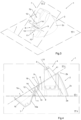
Figure 7 schematically shows the use of a container associated with the cap of the invention for applying a detergent product at the level of the rim of a toilet; -
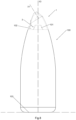
Figure 8 shows a container according to the invention, with which the cap of the invention is associated. - The flip-top cap according to the invention, which can be associated with thin-walled flexible containers, is shown in Figures from 1 to 6, where it is indicated as a whole by 1.
- Said cap 1 comprises a
tubular body 2 in which, at afirst end 2a lying on a first plane π1, coupling means 3 are defined for coupling the same cap 1 and acontainer 100 together. - In addition, the cap 1 is provided with a
dispenser tube 4, visible in Figures from 4 to 6, comprising atubular wall 41 that defines adispenser mouth 5 of the cap 1 according to a main axis X1, through which the contents of thecontainer 100 are dispensed. - The
dispenser tube 4, as can be observed inFigure 4 , extends projecting from asurface 6 defined at thesecond end 2b of thetubular body 2, so that the main axis X1 is substantially orthogonal to thesurface 6. - Furthermore, the cap 1 comprises a
top closing element 7 hinged to thetubular body 2 through hinge means 8, so as to allow thetop closing element 7 to rotate around a hinge axis Y1 orthogonal to the main axis X1. - The
top closing element 7 is suited to close thedispenser mouth 5 of thedispenser tube 4. - According to the invention, the
surface 6 lies on a second plane π2 incident on the first plane π1, as can be seen inFigures 1 ,3 ,4 and6 , so that the main axis X1 is oblique with respect to the first plane π1. Furthermore, according to the invention, thetop closing element 7 is hinged to thetubular body 2 at afirst section 9 of thesecond end 2b of thetubular body 2 itself, facing towards the line of incidence r between the first plane π1 and said second plane π2. - The combination of features described above has the advantage of making it possible to provide a flip-top cap that can be applied to the same containers to which the known flip-top caps are applied, and at the same time makes it possible to define a dispensing direction of the contents of such containers that is oblique with respect to the extension axis of the containers themselves. This makes it possible to easily fill containers at the industrial stage, while at the same time allowing the container with the associated cap 1 of the invention to be used to apply said contents to areas without direct access, such as for example the rim of a toilet.
- Furthermore, the fact that the
top closing element 7 is hinged to thetubular body 2 at saidfirst section 9 allows the sametop closing element 7, when the cap 1 is open, not to hinder the approaching movement of thedispenser mouth 5, for example, to the rim B of a toilet, as schematically shown inFigure 7 . - In particular, according to a preferred embodiment of the invention, the
top closing element 7 is configured to rotate around the hinge axis Y1 from a closed position, in which thetop closing element 7 itself closes thedispenser mouth 5, to a completely open position, according to which thebottom 7a of saidtop closing element 7 is substantially coplanar with thesurface 6. Advantageously, said last detail feature provides a better guarantee that thetop closing element 7 is not an obstacle to the approaching movement of thedispenser mouth 5 towards the rim of a toilet, for example. - According to an embodiment of the invention, the cap 1 is also provided with first locking means 11, at the
portion 10 of theside wall 2c of thetubular body 2 facing towards the line of incidence r, and with second locking means 12, complementary to the first locking means 11, at theouter wall 7b of thetop closing element 7 facing theportion 10 of theside wall 2c, when thetop closing element 7 is in the completely open position. - In this way, advantageously, the first locking means 11 and the second locking means 12 are configured to be reversibly coupled together and keep the
top closing element 7 locked in the completely open position. This makes it possible to keep thetop closing element 7 in the completely open position when applying the contents of the container at the level of the rim of a toilet, for example, thus preventing thetop closing element 7 from moving and hindering said application. - More specifically, according to the latter embodiment, the first locking means 11 comprise a
locking tooth 13 projecting from theportion 10 of theside wall 2c and the second locking means 12 comprise a locking opening 14 in which thelocking tooth 13 is suited to become engaged by interference, when thetop closing element 7 is in the completely open position. - According to a further aspect of the invention, in an embodiment of the cap 1 the
dispenser tube 4 has substantially the shape of a truncated cone, as can be observed inFigure 4 . - This, advantageously, allows the
dispenser tube 4 to wedge through easier to the toilet rim, for example. - Furthermore, according to an embodiment of the invention, according to a cross section plane π3, on which the main axis X1 lies, the
top closing element 7 is substantially in the shape of ascalene trapezoid 15, in which thelower portion 16 of the longeroblique side 15a is hinged to thetubular body 2. Said characteristic advantageously makes it easier to ensure the coplanarity of thebottom 7a of thetop closing element 7 with respect to thesurface 6, when thetop closing element 7 itself is in the completely open position, as shown inFigure 4 . - Furthermore, according to the preferred embodiment of the invention, the cap 1 is configured so that the
tubular body 2 comprises first coupling means 18 at asecond section 17 of thesecond end 2b, diametrically opposite the hinge means 8. Furthermore, it is provided that thetop closing element 7, at its portion facing the first coupling means 18, when it is in said closed position, comprises second coupling means 19, complementary to the first coupling means 18, so that said first coupling means 18 are reversibly engaged with the second coupling means 19, as shown inFigure 2 . This, advantageously, makes it possible to keep the cap 1 closed in a stable manner and to prevent the cap itself from opening accidentally. - As mentioned above, a thin-walled
flexible container 100, shown inFigure 8 and preferably suitable for holding toilet cleaners, is also part of the invention. Said container has a substantially longitudinal extension along an extension axis X3. According to the invention, saidcontainer 100 comprises a cap 1 of the invention coupled thereto at itsdispenser mouth 101. - In particular, the
dispenser mouth 101 of thecontainer 100 is defined on asurface 102 substantially parallel to thebottom 103 of the container itself and perpendicular to the extension axis X3. In this way, thecontainer 100 remains easy to be filled at an industrial level. - The cap 1 of the invention is coupled with the
container 100 through coupling means 3 at the level ofsaid surface 102, so that the main axis X1 of the same cap 1 is oblique with respect to thebottom 103 and the longitudinal axis X3. As a result of what has been described above, it can be understood that the flip-top cap of the invention and the container to which said cap of the invention is applied achieve all the set objects. - More specifically, the object to provide a flip-top cap suited to be applied to containers whose dispenser mouth is parallel to the extension axis of the container and, at the same time, which are suited to be used for the application, for example, of toilet detergents or other detergents at the level of the rim of a toilet or at any other area without direct access is achieved. Even more specifically, the object to provide a flip-top cap which makes such particular uses possible and which, at the same time, can be associated with containers that are easier to fill industrially than the containers specifically made for such uses is achieved.
Claims (10)
- Flip-top cap (1) for thin-walled flexible containers (100), comprising:- a tubular body (2) in which, at a first end (2a) lying on a first plane (π1), coupling means (3) are defined for coupling said cap (1) to one of said containers (100);- a dispenser tube (4) comprising a tubular wall (41) defining a dispenser mouth (5) of said cap (1) according to a main axis (X1), wherein said dispenser tube (4) extends so as to project from a surface (6) defined at the second end (2b) of said tubular body (2) so that said main axis (X1) is substantially orthogonal to said surface (6);- a top closing element (7) hinged to said tubular body (2) by means of hinging means (8) for rotating said top closing element (7) about a hinge axis (Y1) orthogonal to the main axis (X1), said top closing element (7) being suitable for closing said dispenser mouth (5) of said dispenser tube (4);wherein said surface (6) lies on a second plane (π2) incident on said first plane (π1), so that said main axis (X1) is oblique with respect to said first plane (π1), the cap (1) being characterized in that said top closing element (7) is hinged to said tubular body (2) at a first section (9) of said second end (2b) facing towards the line of incidence (r) between said first plane (π1) and said second plane (π2).
- Cap (1) according to claim 1, characterized in that said top closing element (7) is configured to rotate around said hinge axis (Y1) from a closed position, in which said top closing element (7) closes said dispenser mouth (5), to a completely open position, according to which the bottom (7a) of said top closing element (7) is substantially coplanar with said surface (6).
- Cap (1) according to claim 2, characterized in that:- first locking means (11) are defined at the portion (10) of the side wall (2c) of said tubular body (2) facing towards said line of incidence (r);- second locking means (12) complementary to said first locking means (11) are defined on the outer wall (7b) of said top closing element (7) facing said portion (10) of said side wall (2c) when said top closing element (7) is in said completely open position, said first locking means (11) and said second locking means (12) being configured to be reversibly coupled together and maintain said top closing element (7) locked in said completely open position.
- Cap (1) according to claim 3, characterized in that said first locking means (11) comprise a locking tooth (13) projecting from said portion (10) of said side wall (2c) and said second locking means (12) comprise a locking opening (14) in which said locking tooth (13) can become engaged by interference when said top closing element (7) is in said completely open position.
- Cap (1) according to any of the preceding claims, characterized in that said dispenser tube (4) is substantially in the shape of a truncated cone.
- Cap (1) according to any of the preceding claims, characterized in that, according to a cross section plane (π3) on which said main axis (X1) lies, said top closing element (7) has substantially the shape of a scalene trapezoid (15), in which the lower portion (16) of the longer oblique side (15a) is hinged to said tubular body (2).
- Cap (1) according to any of the preceding claims, characterized in that:- first coupling means (18) are defined in said tubular body (2) at a second section (17) of said second end (2b) diametrically opposite said hinge means (8);- said top closing element (7), at its portion facing said first coupling means (18), when it is in the closed position, comprises second coupling means (19) complementary to said first coupling means (18) in such a manner that said first coupling means (18) are reversibly coupled with said second coupling means (19).
- Thin-walled flexible container (100) preferably suited to contain toilet cleaners, substantially extending longitudinally along an extension axis (X3), characterized in that it comprises, coupled thereto at its dispenser mouth (101), a cap (1) according to any of the preceding claims.
- Container (100) according to claim 8, characterized in that said dispenser mouth (101) is defined on a surface (102) which is substantially parallel to the bottom (103) of said container (100) and perpendicular to said extension axis (X3).
- Container (100) according to claim 9, characterized in that said cap (1) is coupled with said container (100) through said coupling means (3) at the level of said surface (102) in such a way that said main axis (X1) of said cap (1) is oblique with respect to said bottom (103) and to said longitudinal axis (X3).
Applications Claiming Priority (1)
| Application Number | Priority Date | Filing Date | Title |
|---|---|---|---|
| IT102023000013515A IT202300013515A1 (en) | 2023-06-29 | 2023-06-29 | FLIP-TOP CAP AND CONTAINER WITH WHICH THE CAP IS ASSOCIATED |
Publications (2)
| Publication Number | Publication Date |
|---|---|
| EP4484322A1 true EP4484322A1 (en) | 2025-01-01 |
| EP4484322B1 EP4484322B1 (en) | 2026-03-04 |
Family
ID=88097740
Family Applications (1)
| Application Number | Title | Priority Date | Filing Date |
|---|---|---|---|
| EP24185112.0A Active EP4484322B1 (en) | 2023-06-29 | 2024-06-27 | Flip-top cap and container with which said cap is associated |
Country Status (5)
| Country | Link |
|---|---|
| EP (1) | EP4484322B1 (en) |
| ES (1) | ES3071603T3 (en) |
| IT (1) | IT202300013515A1 (en) |
| PL (1) | PL4484322T3 (en) |
| PT (1) | PT4484322T (en) |
Citations (7)
| Publication number | Priority date | Publication date | Assignee | Title |
|---|---|---|---|---|
| US3254812A (en) * | 1964-05-05 | 1966-06-07 | Lever Brothers Ltd | Closure structure for containers for granular products |
| DE2930529A1 (en) * | 1979-07-27 | 1981-06-04 | Franz 7500 Karlsruhe Kutterer | Liquid tight closure for tubes - has spout fitting slid over outlet with attached closure cap pressed on spout |
| DE8421061U1 (en) * | 1984-07-13 | 1985-11-07 | Weener Plastik Gmbh & Co Kg, 2952 Weener | Container closure mouthpiece with hinged hinged lid |
| US4949883A (en) * | 1988-01-26 | 1990-08-21 | Alfatechnic Ag | One-piece plastic closure with a hinge |
| US5605254A (en) * | 1995-03-01 | 1997-02-25 | George J. Wagner, III | Ventilated directional dispensing cap |
| US6050274A (en) * | 1998-12-03 | 2000-04-18 | Anthony L. Gelardi | Applicator |
| US20040050883A1 (en) * | 2002-09-17 | 2004-03-18 | George J. Wagner Iii | Aerated rapid flow dispensing cap |
-
2023
- 2023-06-29 IT IT102023000013515A patent/IT202300013515A1/en unknown
-
2024
- 2024-06-27 PL PL24185112.0T patent/PL4484322T3/en unknown
- 2024-06-27 ES ES24185112T patent/ES3071603T3/en active Active
- 2024-06-27 PT PT241851120T patent/PT4484322T/en unknown
- 2024-06-27 EP EP24185112.0A patent/EP4484322B1/en active Active
Patent Citations (7)
| Publication number | Priority date | Publication date | Assignee | Title |
|---|---|---|---|---|
| US3254812A (en) * | 1964-05-05 | 1966-06-07 | Lever Brothers Ltd | Closure structure for containers for granular products |
| DE2930529A1 (en) * | 1979-07-27 | 1981-06-04 | Franz 7500 Karlsruhe Kutterer | Liquid tight closure for tubes - has spout fitting slid over outlet with attached closure cap pressed on spout |
| DE8421061U1 (en) * | 1984-07-13 | 1985-11-07 | Weener Plastik Gmbh & Co Kg, 2952 Weener | Container closure mouthpiece with hinged hinged lid |
| US4949883A (en) * | 1988-01-26 | 1990-08-21 | Alfatechnic Ag | One-piece plastic closure with a hinge |
| US5605254A (en) * | 1995-03-01 | 1997-02-25 | George J. Wagner, III | Ventilated directional dispensing cap |
| US6050274A (en) * | 1998-12-03 | 2000-04-18 | Anthony L. Gelardi | Applicator |
| US20040050883A1 (en) * | 2002-09-17 | 2004-03-18 | George J. Wagner Iii | Aerated rapid flow dispensing cap |
Also Published As
| Publication number | Publication date |
|---|---|
| IT202300013515A1 (en) | 2024-12-29 |
| ES3071603T3 (en) | 2026-06-24 |
| PL4484322T3 (en) | 2026-07-06 |
| PT4484322T (en) | 2026-05-06 |
| EP4484322B1 (en) | 2026-03-04 |
Similar Documents
| Publication | Publication Date | Title |
|---|---|---|
| EP0826606B1 (en) | Dispensing cap with improved gripping means | |
| KR910002434B1 (en) | Spout for packaging containers | |
| ES2314221T3 (en) | PAINT CONTAINER. | |
| US7040499B1 (en) | Container with primary closure and a secondary closure | |
| US4377248A (en) | Dispensing cap construction | |
| US20040155045A1 (en) | Closing element with outlet channel extending in funnel-like manner | |
| US20080110942A1 (en) | Closure With One Or More Lids | |
| ES2473815T3 (en) | Closure that facilitates the pouring from an inverted container | |
| FR2612159A1 (en) | Package with a container and a safety pouring stopper | |
| EA038679B1 (en) | Closure | |
| US5421487A (en) | Dispenser cap for a fluid substance container, with a movable dispensing nozzle | |
| CH636819A5 (en) | CLOSING CAP WITH RETRACTABLE SPOUT FOR A CONTAINER WITH A NECK. | |
| US6216945B1 (en) | Pouring element | |
| EP4484322B1 (en) | Flip-top cap and container with which said cap is associated | |
| FR2804755A1 (en) | DOSING DEVICE FOR LIQUID PRODUCTS CONTAINED IN BOTTLES OR THE LIKE | |
| PT92339A (en) | DEVICE FOR EMPTYING PACKAGING CONTAINERS, IN PARTICULAR, PACKAGING TYPE CONTAINING A BAG | |
| RU2493073C2 (en) | Container | |
| US20110297705A1 (en) | Reclosable Dispensing Container Cap For Flowable Material Containers | |
| EP0154897A2 (en) | A metering dispenser cover with shut-off lever, particularly for jars and the like containers of syrupy and/or viscous fluids, incoherent products, and the like | |
| FR2848992A1 (en) | Cap for container of fluid product, e.g. cosmetic or pharmaceutical, has opening top with flexible tongue held under ring to guarantee that it has not been opened. | |
| JPH1072053A (en) | Cap with lid | |
| JP7387229B2 (en) | hinge cap | |
| WO1995013224A1 (en) | Bagbottle | |
| EP0128070A1 (en) | Laundry or dish washer with detergent dispenser | |
| US20060097006A1 (en) | Pour spout fitment with internal cut off |
Legal Events
| Date | Code | Title | Description |
|---|---|---|---|
| PUAI | Public reference made under article 153(3) epc to a published international application that has entered the european phase |
Free format text: ORIGINAL CODE: 0009012 |
|
| STAA | Information on the status of an ep patent application or granted ep patent |
Free format text: STATUS: THE APPLICATION HAS BEEN PUBLISHED |
|
| AK | Designated contracting states |
Kind code of ref document: A1 Designated state(s): AL AT BE BG CH CY CZ DE DK EE ES FI FR GB GR HR HU IE IS IT LI LT LU LV MC ME MK MT NL NO PL PT RO RS SE SI SK SM TR |
|
| STAA | Information on the status of an ep patent application or granted ep patent |
Free format text: STATUS: REQUEST FOR EXAMINATION WAS MADE |
|
| 17P | Request for examination filed |
Effective date: 20250502 |
|
| GRAP | Despatch of communication of intention to grant a patent |
Free format text: ORIGINAL CODE: EPIDOSNIGR1 |
|
| STAA | Information on the status of an ep patent application or granted ep patent |
Free format text: STATUS: GRANT OF PATENT IS INTENDED |
|
| RIC1 | Information provided on ipc code assigned before grant |
Ipc: B65D 47/08 20060101AFI20250905BHEP |
|
| INTG | Intention to grant announced |
Effective date: 20250922 |
|
| GRAS | Grant fee paid |
Free format text: ORIGINAL CODE: EPIDOSNIGR3 |
|
| GRAA | (expected) grant |
Free format text: ORIGINAL CODE: 0009210 |
|
| STAA | Information on the status of an ep patent application or granted ep patent |
Free format text: STATUS: THE PATENT HAS BEEN GRANTED |
|
| AK | Designated contracting states |
Kind code of ref document: B1 Designated state(s): AL AT BE BG CH CY CZ DE DK EE ES FI FR GB GR HR HU IE IS IT LI LT LU LV MC ME MK MT NL NO PL PT RO RS SE SI SK SM TR |
|
| REG | Reference to a national code |
Ref country code: CH Ref legal event code: F10 Free format text: ST27 STATUS EVENT CODE: U-0-0-F10-F00 (AS PROVIDED BY THE NATIONAL OFFICE) Effective date: 20260304 Ref country code: GB Ref legal event code: FG4D |
|
| REG | Reference to a national code |
Ref country code: DE Ref legal event code: R096 Ref document number: 602024002956 Country of ref document: DE |
|
| REG | Reference to a national code |
Ref country code: IE Ref legal event code: FG4D |
|
| REG | Reference to a national code |
Ref country code: PT Ref legal event code: SC4A Ref document number: 4484322 Country of ref document: PT Date of ref document: 20260506 Kind code of ref document: T Free format text: AVAILABILITY OF NATIONAL TRANSLATION Effective date: 20260429 |
|
| REG | Reference to a national code |
Ref country code: ES Ref legal event code: FG2A Ref document number: 3071603 Country of ref document: ES Kind code of ref document: T3 Effective date: 20260624 |
|
| PG25 | Lapsed in a contracting state [announced via postgrant information from national office to epo] |
Ref country code: RS Free format text: LAPSE BECAUSE OF FAILURE TO SUBMIT A TRANSLATION OF THE DESCRIPTION OR TO PAY THE FEE WITHIN THE PRESCRIBED TIME-LIMIT Effective date: 20260604 |
|
| REG | Reference to a national code |
Ref country code: NL Ref legal event code: MP Effective date: 20260304 |
|
| PGFP | Annual fee paid to national office [announced via postgrant information from national office to epo] |
Ref country code: PL Payment date: 20260619 Year of fee payment: 3 |
|
| PG25 | Lapsed in a contracting state [announced via postgrant information from national office to epo] |
Ref country code: GR Free format text: LAPSE BECAUSE OF FAILURE TO SUBMIT A TRANSLATION OF THE DESCRIPTION OR TO PAY THE FEE WITHIN THE PRESCRIBED TIME-LIMIT Effective date: 20260605 |
|
| REG | Reference to a national code |
Ref country code: LT Ref legal event code: MG9D |
|
| PG25 | Lapsed in a contracting state [announced via postgrant information from national office to epo] |
Ref country code: LT Free format text: LAPSE BECAUSE OF FAILURE TO SUBMIT A TRANSLATION OF THE DESCRIPTION OR TO PAY THE FEE WITHIN THE PRESCRIBED TIME-LIMIT Effective date: 20260304 |
|
| PGFP | Annual fee paid to national office [announced via postgrant information from national office to epo] |
Ref country code: DE Payment date: 20260622 Year of fee payment: 3 |
|
| PG25 | Lapsed in a contracting state [announced via postgrant information from national office to epo] |
Ref country code: NO Free format text: LAPSE BECAUSE OF FAILURE TO SUBMIT A TRANSLATION OF THE DESCRIPTION OR TO PAY THE FEE WITHIN THE PRESCRIBED TIME-LIMIT Effective date: 20260604 |
|
| PG25 | Lapsed in a contracting state [announced via postgrant information from national office to epo] |
Ref country code: SE Free format text: LAPSE BECAUSE OF FAILURE TO SUBMIT A TRANSLATION OF THE DESCRIPTION OR TO PAY THE FEE WITHIN THE PRESCRIBED TIME-LIMIT Effective date: 20260304 Ref country code: FI Free format text: LAPSE BECAUSE OF FAILURE TO SUBMIT A TRANSLATION OF THE DESCRIPTION OR TO PAY THE FEE WITHIN THE PRESCRIBED TIME-LIMIT Effective date: 20260304 |
|
| PGFP | Annual fee paid to national office [announced via postgrant information from national office to epo] |
Ref country code: RO Payment date: 20260625 Year of fee payment: 3 Ref country code: BE Payment date: 20260618 Year of fee payment: 3 |
|
| PG25 | Lapsed in a contracting state [announced via postgrant information from national office to epo] |
Ref country code: HR Free format text: LAPSE BECAUSE OF FAILURE TO SUBMIT A TRANSLATION OF THE DESCRIPTION OR TO PAY THE FEE WITHIN THE PRESCRIBED TIME-LIMIT Effective date: 20260304 |
|
| PGFP | Annual fee paid to national office [announced via postgrant information from national office to epo] |
Ref country code: PT Payment date: 20260618 Year of fee payment: 3 |
|
| PGFP | Annual fee paid to national office [announced via postgrant information from national office to epo] |
Ref country code: CZ Payment date: 20260624 Year of fee payment: 3 |
|
| PGFP | Annual fee paid to national office [announced via postgrant information from national office to epo] |
Ref country code: FR Payment date: 20260626 Year of fee payment: 3 |
|
| PG25 | Lapsed in a contracting state [announced via postgrant information from national office to epo] |
Ref country code: LV Free format text: LAPSE BECAUSE OF FAILURE TO SUBMIT A TRANSLATION OF THE DESCRIPTION OR TO PAY THE FEE WITHIN THE PRESCRIBED TIME-LIMIT Effective date: 20260304 |
|
| PG25 | Lapsed in a contracting state [announced via postgrant information from national office to epo] |
Ref country code: BG Free format text: LAPSE BECAUSE OF FAILURE TO SUBMIT A TRANSLATION OF THE DESCRIPTION OR TO PAY THE FEE WITHIN THE PRESCRIBED TIME-LIMIT Effective date: 20260304 |