EP4484298A1 - Système d attache moteur avant pour un moteur d aéronef qui comporte une structure compacte - Google Patents
Système d attache moteur avant pour un moteur d aéronef qui comporte une structure compacte Download PDFInfo
- Publication number
- EP4484298A1 EP4484298A1 EP24184546.0A EP24184546A EP4484298A1 EP 4484298 A1 EP4484298 A1 EP 4484298A1 EP 24184546 A EP24184546 A EP 24184546A EP 4484298 A1 EP4484298 A1 EP 4484298A1
- Authority
- EP
- European Patent Office
- Prior art keywords
- main
- shaft
- engine
- axis
- attachment system
- Prior art date
- Legal status (The legal status is an assumption and is not a legal conclusion. Google has not performed a legal analysis and makes no representation as to the accuracy of the status listed.)
- Granted
Links
Images



Classifications
-
- B—PERFORMING OPERATIONS; TRANSPORTING
- B64—AIRCRAFT; AVIATION; COSMONAUTICS
- B64D—EQUIPMENT FOR FITTING IN OR TO AIRCRAFT; FLIGHT SUITS; PARACHUTES; ARRANGEMENT OR MOUNTING OF POWER PLANTS OR PROPULSION TRANSMISSIONS IN AIRCRAFT
- B64D27/00—Arrangement or mounting of power plants in aircraft; Aircraft characterised by the type or position of power plants
- B64D27/02—Aircraft characterised by the type or position of power plants
- B64D27/10—Aircraft characterised by the type or position of power plants of gas-turbine type
- B64D27/12—Aircraft characterised by the type or position of power plants of gas-turbine type within, or attached to, wings
-
- B—PERFORMING OPERATIONS; TRANSPORTING
- B64—AIRCRAFT; AVIATION; COSMONAUTICS
- B64D—EQUIPMENT FOR FITTING IN OR TO AIRCRAFT; FLIGHT SUITS; PARACHUTES; ARRANGEMENT OR MOUNTING OF POWER PLANTS OR PROPULSION TRANSMISSIONS IN AIRCRAFT
- B64D27/00—Arrangement or mounting of power plants in aircraft; Aircraft characterised by the type or position of power plants
- B64D27/40—Arrangements for mounting power plants in aircraft
- B64D27/402—Arrangements for mounting power plants in aircraft comprising box like supporting frames, e.g. pylons or arrangements for embracing the power plant
-
- F—MECHANICAL ENGINEERING; LIGHTING; HEATING; WEAPONS; BLASTING
- F02—COMBUSTION ENGINES; HOT-GAS OR COMBUSTION-PRODUCT ENGINE PLANTS
- F02C—GAS-TURBINE PLANTS; AIR INTAKES FOR JET-PROPULSION PLANTS; CONTROLLING FUEL SUPPLY IN AIR-BREATHING JET-PROPULSION PLANTS
- F02C7/00—Features, components parts, details or accessories, not provided for in, or of interest apart form groups F02C1/00 - F02C6/00; Air intakes for jet-propulsion plants
-
- B—PERFORMING OPERATIONS; TRANSPORTING
- B64—AIRCRAFT; AVIATION; COSMONAUTICS
- B64D—EQUIPMENT FOR FITTING IN OR TO AIRCRAFT; FLIGHT SUITS; PARACHUTES; ARRANGEMENT OR MOUNTING OF POWER PLANTS OR PROPULSION TRANSMISSIONS IN AIRCRAFT
- B64D27/00—Arrangement or mounting of power plants in aircraft; Aircraft characterised by the type or position of power plants
- B64D27/40—Arrangements for mounting power plants in aircraft
-
- B—PERFORMING OPERATIONS; TRANSPORTING
- B64—AIRCRAFT; AVIATION; COSMONAUTICS
- B64D—EQUIPMENT FOR FITTING IN OR TO AIRCRAFT; FLIGHT SUITS; PARACHUTES; ARRANGEMENT OR MOUNTING OF POWER PLANTS OR PROPULSION TRANSMISSIONS IN AIRCRAFT
- B64D27/00—Arrangement or mounting of power plants in aircraft; Aircraft characterised by the type or position of power plants
- B64D27/40—Arrangements for mounting power plants in aircraft
- B64D27/404—Suspension arrangements specially adapted for supporting vertical loads
-
- F—MECHANICAL ENGINEERING; LIGHTING; HEATING; WEAPONS; BLASTING
- F02—COMBUSTION ENGINES; HOT-GAS OR COMBUSTION-PRODUCT ENGINE PLANTS
- F02C—GAS-TURBINE PLANTS; AIR INTAKES FOR JET-PROPULSION PLANTS; CONTROLLING FUEL SUPPLY IN AIR-BREATHING JET-PROPULSION PLANTS
- F02C6/00—Plural gas-turbine plants; Combinations of gas-turbine plants with other apparatus; Adaptations of gas-turbine plants for special use
- F02C6/20—Adaptations of gas-turbine plants for driving vehicles
Definitions
- the present invention relates to a front engine attachment system for an aircraft engine where the front engine attachment system is compact, as well as to an aircraft comprising at least one such front engine attachment.
- An aircraft typically has at least one engine, in particular a turbojet. Under each wing and for each engine, the aircraft has a reactor pylon which is fixed to the wing structure and which extends below the wing and the engine is suspended under the reactor pylon.
- the engine is housed in a nacelle and attached to the engine pylon by an engine attachment system comprising a front engine attachment and a rear engine attachment.
- An object of the present invention is to provide a front engine attachment system which integrates the engine pylon and the front engine attachment to reduce the height of the assembly.
- Such a front engine attachment system has a reduced vertical footprint because the front engine attachment is integrated into the engine pylon.
- the main axis is arranged in front of the vertical axis.
- the front engine attachment system comprises an inner cylinder inserted and fixed in the outer cylinder.
- the nose comprises two lateral stops arranged respectively to the port and starboard sides of the outer cylinder and which are intended to come between two lateral counter-stops of the front casing.
- the front engine attachment system comprises two lateral connecting rods arranged respectively to the port and starboard of the main connecting rod, and each lateral connecting rod is mounted on the main shaft with a tight fit and on the secondary shaft with clearance.
- the main shaft consists of a peripheral shaft which is hollow and an internal shaft which is housed in the peripheral shaft.
- the secondary shaft consists of a peripheral shaft which is hollow and an internal shaft which is housed in the peripheral shaft.
- the invention also proposes an aircraft comprising a structure, an engine with a front casing and a front engine attachment system according to one of the preceding variants, where the main connecting rod is fixed to the front casing by the secondary ball joint and where the second end of the outer cylinder is mounted to move through the annular linear connection around the vertical axis relative to the front casing.
- FIG. 1 shows an aircraft 100 which has an engine 102, in particular a turbojet which is fixed under a reactor mast 104 itself fixed under a wing 106.
- X is the longitudinal direction of the engine 102 oriented positively in the direction of advancement of the aircraft 100
- Y is the transverse direction of the engine 102 which is horizontal when the aircraft 100 is on the ground
- Z is the vertical direction or vertical height when the aircraft 100 is on the ground, these three directions X, Y and Z being orthogonal to each other.
- the engine 102 generally has a shape of revolution around the longitudinal axis X.
- the aircraft 100 comprises an engine 102 under each wing 106 of the aircraft 100, but it is possible to provide several engines under each wing 106.
- FIG. 2 shows a front engine attachment system 150 which is fixed to the structure of the aircraft 100, here the structure of the wing 106, and extends under the wing 106 and supports the engine 102 and in particular the front part of the engine 102.
- Figs. 2 to 4 show different views of the 150 front engine mounting system.
- the front engine attachment system 150 comprises the engine pylon 104 fixed to the wing structure 106 and a front engine attachment 160 fixed between the engine pylon 104 and a front casing 103 secured to the engine 102.
- the front engine attachment system 150 comprises a vertical median plane XZ.
- a rear engine attachment is fixed between the engine pylon 104 and a rear portion of the engine 102 and it can take any form known to those skilled in the art.
- the engine pylon 104 takes the form of a box which comprises, among other things, at a front portion 163, a nose 110 which comprises a main female yoke 111 consisting of two walls 110a-b which are parallel to each other and vertical, i.e. parallel to the median plane XZ and therefore perpendicular to the transverse direction Y.
- the main female yoke 111 allows the installation of a connecting rod which is mounted freely rotatable in the main female yoke 111 around a main axis 10 oriented transversely, i.e.
- the nose 110 is made up of two fittings 109a-b fixed to each other at the median plane XZ and each wall 110a-b constituting the main female yoke 111 belongs to one of the fittings 109a-b, and the two walls 110a-b are here symmetrical with respect to the median plane XZ.
- FIG. 3 shows a section at the level of the main female yoke 111 and a secondary female yoke 103a.
- the reactor mast 104 comprises an upper wall 104a, a lower wall 104b and two side walls 104c-d.
- the different walls 104a-d are integral with each other so as to form a box whose vertical section is generally trapezoidal.
- the nose 110 is fixed at the level of the front zone 163 of the reactor mast 104 by any known means, such as for example by welding or bolts.
- the front zone 163 corresponds to the front ends of the walls 104a-d.
- the front engine mount 160 comprises a main connecting rod 162 fixed to the nose 110 in the main female yoke 111.
- the main ball joint connection of the main connecting rod 162 in the main female yoke 111 is made by a main shaft 165 which is equipped with a nut 171 on which the main connecting rod 162 is articulated.
- the main shaft 165 passes through the two walls 110a-b forming the main female yoke 111 and the main connecting rod 162 through bores provided for this purpose.
- the main shaft 165 is thus perpendicular to the median plane XZ.
- the main axis 10 constitutes the axis of the main shaft 165.
- the main connecting rod 162 is also fixed in an articulated manner to the front casing 103 by a secondary ball joint, a main axis of rotation of which is a secondary axis 12 perpendicular to the median plane XZ and therefore horizontal and where the rotations according to the other two axes are of reduced amplitudes.
- the front casing 103 has the secondary female yoke 103a which is also made up of two walls which are parallel to each other and vertical, that is to say parallel to the median plane XZ and here symmetrical with respect to the median plane XZ.
- the fixing of the main connecting rod 162 to the secondary female yoke 103a is ensured by a secondary shaft 167 which passes through the two walls forming the secondary female yoke 103a and the main connecting rod 162 through bores provided for this purpose.
- the secondary shaft 167 is thus perpendicular to the median plane XZ.
- the secondary axis 12 constitutes the axis of the secondary shaft 167.
- the secondary ball joint connection of the main connecting rod 162 with the front casing 103 is produced by the secondary shaft 167 which is equipped with a nut 174 on which the main connecting rod 162 is articulated.
- the secondary axis 12 is vertically aligned with the main axis 10 and below the latter, that is to say that the axis of the secondary shaft 167 and the axis of the main shaft 165 are in the same vertical plane perpendicular to the longitudinal direction X and therefore to the median plane XZ, or in other words that the main axis of the main ball joint, that is to say the main axis 10, and the main axis of the secondary ball joint, that is to say the secondary axis 12, are in the same vertical plane perpendicular to the median plane XZ.
- the main connecting rod 162 is mounted with an interference fit via the nuts 171 and 174 on the main shaft 165 and on the secondary shaft 167.
- the main shaft 165 is mounted inside the bores of the main female yoke 111 via rotary bearings.
- the secondary shaft 167 is mounted inside the bores of the secondary female yoke 103a with an interference fit.
- FIG. 4 shows a section at the level of an annular linear connection where the translation axis is a vertical axis 20 also called a “spigot connection” 169.
- the nose 110 has a cylindrical housing 502 coaxial with the vertical axis 20 which is therefore oriented vertically and here in the vertical median plane XZ.
- the front engine mount 160 also includes an outer cylinder 504, a first end of which is fixed in the cylindrical housing 502 so that the outer cylinder 504 is coaxial with the vertical axis 20.
- the second end of the outer cylinder 504 is mounted to move through an annular linear connection around the vertical axis 20 relative to the front casing 103.
- the ball joint connection is achieved by fitting a nut 506 mounted around the outer cylinder 504 on which the front casing 103 is hingedly mounted.
- the nut 506 is between the outer cylinder 504 and the front casing 103 in which a hole 508 is made to allow the nut 506 and the second end of the outer cylinder 504 to be fitted.
- the outer cylinder 504 is hollow and the front engine mount 160 also includes an inner cylinder 505 which is inserted and fixed in the outer cylinder 504.
- the inner cylinder 505 is therefore also coaxial with the vertical axis 20.
- the outer diameter of the inner cylinder 505 is less than the inner diameter of the outer cylinder 504 to create a space 507 between them, i.e. between the inside of the outer cylinder 504 and the outside of the inner cylinder 505.
- the difference in diameter is for example of the order of 0.6 mm to 2 mm and preferably 1 mm.
- the first end of the outer cylinder 504 and the inner cylinder 505 are fixed by placing a pin 503 which is embedded in a bore which passes through the outer cylinder 504, the inner cylinder 505 and the nose 110.
- the axis of the pin 503 is here perpendicular to the vertical axis 20.
- the main female yoke 111 is arranged at the front of the spigot connection 169 relative to the longitudinal direction X, that is to say that the main axis 10 of the main ball joint connection is at the front of the vertical axis 20.
- the mast 104 directly incorporates the elements ensuring the fixing of the motor 102 to reduce the height necessary for this fixing.
- the X and Y forces are transmitted through the spigot connection 169.
- the front engine attachment system 150 also includes means which provide secondary force paths which compensate for a failure of the primary force path, these means constituting waiting fail-safe means.
- the nose 110 then comprises two lateral stops 512a-b which are arranged respectively to port and starboard of the outer cylinder 504 and, for each lateral stop 512a-b, the front casing 103 comprises a lateral counter-stop 510a-b and the two lateral counter-stops 510a-b are also arranged respectively to port and starboard of the outer cylinder 504 and the lateral stops 512a-b are arranged between the lateral counter-stops 510a-b.
- each lateral stop 512a-b In the normal position, that is to say without failure of the primary force path, each lateral stop 512a-b is at a distance from the associated lateral counter-stop 510a-b, and in the event of failure, one of the lateral stops 512a-b comes to bear against the associated lateral counter-stop 510a-b.
- the inner cylinder 505 takes over and thus forms a waiting fail-safe.
- the front engine attachment system 150 comprises two lateral connecting rods 170a-b arranged respectively to port and starboard of the main connecting rod 162, and in the embodiment of the invention presented to the Figs. 2 And 3 , respectively to port and starboard of the walls 110a-b forming the main female yoke 111 and symmetrically with respect to the median plane XZ.
- Each side rod 170a-b is mounted on the main shaft 165 with an interference fit and on the secondary shaft 167 with clearance. Thus, in certain failure cases, at least one side rod 170a-b and/or the secondary shaft 167 will move to bring the inner wall of the bore of said at least one side rod 170a-b against the secondary shaft 167.
- the main shaft 165 consists of a peripheral shaft 165a which is cylindrical and hollow and an inner shaft 165b which is housed in the peripheral shaft 165a.
- a peripheral shaft 165a which is cylindrical and hollow
- an inner shaft 165b which is housed in the peripheral shaft 165a.
- the secondary shaft 167 consists of a peripheral shaft 167a which is cylindrical and hollow and an inner shaft 167b which is housed in the peripheral shaft 167a.
- a peripheral shaft 167a which is cylindrical and hollow
- an inner shaft 167b which is housed in the peripheral shaft 167a.
Landscapes
- Engineering & Computer Science (AREA)
- Aviation & Aerospace Engineering (AREA)
- Chemical & Material Sciences (AREA)
- Combustion & Propulsion (AREA)
- Mechanical Engineering (AREA)
- General Engineering & Computer Science (AREA)
- Pivots And Pivotal Connections (AREA)
- Transmission Devices (AREA)
- Structures Of Non-Positive Displacement Pumps (AREA)
- Shafts, Cranks, Connecting Bars, And Related Bearings (AREA)
- Mutual Connection Of Rods And Tubes (AREA)
Abstract
Description
- La présente invention concerne un système d'attache moteur avant pour un moteur d'aéronef où le système d'attache moteur avant est compact, ainsi qu'un aéronef comportant au moins une telle attache moteur avant.
- Un aéronef comporte classiquement au moins un moteur, en particulier un turboréacteur. Sous chaque aile et pour chaque moteur, l'aéronef comporte un mât réacteur qui est fixé à la structure de l'aile et qui s'étend en-dessous de l'aile et le moteur est suspendu sous le mât réacteur.
- Le moteur est logé dans une nacelle et fixé au mât réacteur par l'intermédiaire d'un système d'attache moteur comprenant une attache moteur avant et une attache moteur arrière.
- Il existe de nombreux types d'attache moteur avant qui sont satisfaisantes du point de vue de leur utilisation actuelle. Mais les soufflantes des nouveaux moteurs sont de plus en plus grandes pour améliorer les performances des moteurs, ce qui réduit d'autant la distance entre la nacelle et le sol.
- Il est alors nécessaire de définir un nouvel arrangement permettant de réduire la hauteur de l'attache moteur avant pour éloigner la nacelle du sol et par voie de conséquence de rapprocher la nacelle de l'aile.
- Un objet de la présente invention est de proposer un système d'attache moteur avant qui intègre le mât réacteur et l'attache moteur avant pour réduire la hauteur de l'ensemble.
- À cet effet, est proposé un système d'attache moteur avant pour un moteur d'un aéronef, le système d'attache moteur avant présentant un plan médian vertical et comportant :
- un mât réacteur comportant au niveau d'une partie avant, un nez présentant une chape femelle principale et un logement cylindrique autour d'un axe vertical,
- une bielle principale destinée à être fixée à un carter avant du moteur par une liaison rotule secondaire autour d'un axe secondaire perpendiculaire au plan médian par l'intermédiaire d'un arbre secondaire,
- un arbre principal perpendiculaire au plan médian et réalisant une liaison rotule principale de la bielle principale dans la chape femelle principale autour d'un axe principal, où l'axe principal et l'axe secondaire sont dans un même plan vertical perpendiculaire au plan médian, et
- un cylindre extérieur creux et coaxial avec l'axe vertical, dont une première extrémité est fixée dans le logement cylindrique et dont une deuxième extrémité est destinée à être montée mobile au travers d'une liaison linéaire annulaire autour de l'axe vertical par rapport au carter avant.
- Un tel système d'attache moteur avant présente un encombrement réduit verticalement car l'attache moteur avant est intégrée au mât réacteur.
- Avantageusement, l'axe principal est disposé à l'avant de l'axe vertical.
- Selon un mode de réalisation particulier, le système d'attache moteur avant comporte un cylindre intérieur inséré et fixé dans le cylindre extérieur.
- Selon un autre mode de réalisation particulier, le nez comporte deux butées latérales disposées respectivement à bâbord et à tribord du cylindre extérieur et qui sont destinées à venir entre deux contre-butées latérales du carter avant.
- Avantageusement, le système d'attache moteur avant comporte deux bielles latérales disposées respectivement à bâbord et à tribord de la bielle principale, et chaque bielle latérale est montée sur l'arbre principal avec un ajustement serré et sur l'arbre secondaire avec jeu. Avantageusement, l'arbre principal est constitué d'un arbre périphérique qui est creux et d'un arbre intérieur qui est logé dans l'arbre périphérique.
- Avantageusement, l'arbre secondaire est constitué d'un arbre périphérique qui est creux et d'un arbre intérieur qui est logé dans l'arbre périphérique.
- L'invention propose également un aéronef comportant une structure, un moteur avec un carter avant et un système d'attache moteur avant selon l'une des variantes précédentes, où la bielle principale est fixée au carter avant par la liaison rotule secondaire et où la deuxième extrémité du cylindre extérieur est montée mobile au travers de la liaison linéaire annulaire autour de l'axe vertical par rapport au carter avant.
- Les caractéristiques de l'invention mentionnées ci-dessus, ainsi que d'autres, apparaîtront plus clairement à la lecture de la description suivante d'un exemple de réalisation, ladite description étant faite en relation avec les dessins joints, parmi lesquels :
-
Fig. 1 est une vue de côté d'un aéronef selon l'invention, -
Fig. 2 est une vue en perspective d'un système d'attache moteur avant selon l'invention, -
Fig. 3 est une vue en perspective d'une coupe du système d'attache moteur avant selon l'invention au niveau de la ligne III de laFig. 2 , -
Fig. 4 est une vue en perspective d'une coupe du système d'attache moteur avant selon l'invention au niveau de la ligne IV de laFig. 2 -
Fig. 5 est une vue similaire à laFig. 4 pour une variante de réalisation. - Dans la description qui suit, les termes relatifs à une position sont pris en référence à un aéronef en position d'avancement, c'est-à-dire comme il est représenté sur la
Fig. 1 , où la flèche F représente la direction d'avancement. - La
Fig. 1 montre un aéronef 100 qui présente un moteur 102, en particulier un turboréacteur qui est fixé sous un mât réacteur 104 lui-même fixé sous une aile 106. - Dans la description qui suit, et par convention, on appelle X la direction longitudinale du moteur 102 orientée positivement dans le sens d'avancement de l'aéronef 100, on appelle Y la direction transversale du moteur 102 qui est horizontale lorsque l'aéronef 100 est au sol, et Z la direction verticale ou hauteur verticale lorsque l'aéronef 100 est au sol, ces trois directions X, Y et Z étant orthogonales entre elles.
- Le moteur 102 présente globalement une forme de révolution autour de l'axe longitudinal X. Dans le mode de réalisation de l'invention présenté sur la
Fig. 1 , l'aéronef 100 comporte un moteur 102 sous chaque aile 106 de l'aéronef 100, mais il est possible de prévoir plusieurs moteurs sous chaque aile 106. - La
Fig. 2 montre un système d'attache moteur avant 150 qui est fixé à la structure de l'aéronef 100, ici la structure de l'aile 106, et s'étend sous l'aile 106 et supporte le moteur 102 et en particulier la partie avant du moteur 102. LesFigs. 2 à 4 montrent différentes vues du système d'attache moteur avant 150. - Le système d'attache moteur avant 150 comprend le mât réacteur 104 fixé à la structure de l'aile 106 et une attache moteur avant 160 fixée entre le mât réacteur 104 et un carter avant 103 solidaire du moteur 102. Le système d'attache moteur avant 150 comporte un plan médian vertical XZ.
- Classiquement, une attache moteur arrière est fixée entre le mât réacteur 104 et une partie arrière du moteur 102 et elle peut prendre toute forme connue de l'homme du métier.
- Le mât réacteur 104 prend la forme d'un caisson qui comporte entre autres au niveau d'une partie avant 163, un nez 110 qui comporte une chape femelle principale 111 constituée de deux parois 110a-b qui sont parallèles entre elles et verticales, c'est-à-dire parallèles au plan médian XZ et donc perpendiculaire à la direction transversale Y. Comme précisé ci-dessous, la chape femelle principale 111 permet la mise en place d'une bielle qui est montée libre en rotation dans la chape femelle principale 111 autour d'un axe principal 10 orienté transversalement, c'est-à-dire perpendiculairement au plan médian XZ et donc horizontalement de manière à réaliser une liaison rotule dite principale dont un axe de rotation principale est l'axe principal 10 et où les rotations selon les deux autres axes sont d'amplitudes réduites.
- Dans le mode de réalisation de l'invention présenté sur les
Figs. 2 à 5 , le nez 110 est constituée de deux ferrures 109a-b fixées l'une à l'autre au niveau du plan médian XZ et chaque paroi 1 10a-b constituant la chape femelle principale 111 appartient à l'une des ferrures 109a-b, et les deux parois 1 10a-b sont ici symétriques par rapport au plan médian XZ. - La
Fig. 3 montre une coupe au niveau de la chape femelle principale 111 et d'une chape femelle secondaire 103a. - Le mât réacteur 104 comporte une paroi supérieure 104a, une paroi inférieure 104b et deux parois latérales 104c-d. Les différentes parois 104a-d sont solidaires les unes des autres de manière à former un caisson dont la section verticale est globalement trapézoïdale. Le nez 110 se fixe au niveau de la zone avant 163 du mât réacteur 104 par tous moyens connus, comme par exemple par soudure ou des boulons. La zone avant 163 correspond aux extrémités avant des parois 104a-d.
- L'attache moteur avant 160 comporte une bielle principale 162 fixée au nez 110 dans la chape femelle principale 111. La liaison rotule principale de la bielle principale 162 dans la chape femelle principale 111 est réalisée par un arbre principal 165 qui est équipé d'une noix 171 sur laquelle est montée articulée la bielle principale 162. L'arbre principal 165 traverse les deux parois 1 10a-b formant la chape femelle principale 111 et la bielle principale 162 à travers des alésages prévus à cet effet. L'arbre principal 165 est ainsi perpendiculaire au plan médian XZ. L'axe principal 10 constitue l'axe de l'arbre principal 165.
- La bielle principale 162 est également fixée de manière articulée au carter avant 103 par une liaison rotule secondaire dont un axe de rotation principal est un axe secondaire 12 perpendiculaire au plan médian XZ et donc horizontal et où les rotations selon les deux autres axes sont d'amplitudes réduites. À cette fin, le carter avant 103 présente la chape femelle secondaire 103a qui est également constituée de deux parois qui sont parallèles entre elles et verticales, c'est-à-dire parallèles au plan médian XZ et ici symétriques par rapport au plan médian XZ. La fixation de la bielle principale 162 à la chape femelle secondaire 103a est assurée par un arbre secondaire 167 qui traverse les deux parois formant la chape femelle secondaire 103a et la bielle principale 162 à travers des alésages prévus à cet effet. L'arbre secondaire 167 est ainsi perpendiculaire au plan médian XZ. L'axe secondaire 12 constitue l'axe de l'arbre secondaire 167. La liaison rotule secondaire de la bielle principale 162 avec le carter avant 103 est réalisée par l'arbre secondaire 167 qui est équipé d'une noix 174 sur laquelle est montée articulée la bielle principale 162.
- L'axe secondaire 12 est aligné verticalement avec l'axe principal 10 et sous ce dernier, c'est-à-dire que l'axe de l'arbre secondaire 167 et l'axe de l'arbre principal 165 sont dans un même plan vertical perpendiculaire à la direction longitudinale X et donc au plan médian XZ, ou en d'autres termes que l'axe principal de la liaison rotule principale, c'est-à-dire l'axe principal 10, et l'axe principal de la liaison rotule secondaire, c'est-à-dire l'axe secondaire 12, sont dans un même plan vertical perpendiculaire au plan médian XZ.
- Dans le mode de réalisation de l'invention présenté à la
Fig. 3 , la bielle principale 162 est montée avec un ajustement serré via les noix 171 et 174 sur l'arbre principal 165 et sur l'arbre secondaire 167. L'arbre principal 165 est monté à l'intérieur des alésages de la chape femelle principale 111 par l'intermédiaire de paliers rotatifs. L'arbre secondaire 167 est monté à l'intérieur des alésages de la chape femelle secondaire 103a avec un ajustement serré. - La
Fig. 4 montre une coupe au niveau d'une liaison linéaire annulaire où l'axe de translation est un axe vertical 20 également appelée « liaison spigot » 169. - Le nez 110 présente un logement cylindrique 502 coaxial avec l'axe vertical 20 qui est donc orienté verticalement et ici dans le plan médian vertical XZ.
- L'attache moteur avant 160 comporte également un cylindre extérieur 504 dont une première extrémité est fixée dans le logement cylindrique 502 de manière à ce que le cylindre extérieur 504 soit coaxial avec l'axe vertical 20.
- La deuxième extrémité du cylindre extérieur 504 est montée mobile au travers d'une liaison linéaire annulaire autour de l'axe vertical 20 par rapport au carter avant 103. Il y a donc une liaison rotule autour d'un axe principal qui est l'axe vertical 20 entre le cylindre extérieur 504 et le carter avant 103, et donc entre le nez 110 et le carter avant 103. Il y a également une liaison glissière dont la direction est parallèle à l'axe vertical 20.
- Dans le mode de réalisation de l'invention présenté à la
Fig. 4 , la liaison rotule est réalisée par la mise en place d'une noix 506 montée autour du cylindre extérieur 504 sur laquelle est monté articulé le carter avant 103. La noix 506 est entre le cylindre extérieur 504 et le carter avant 103 dans lequel un perçage 508 est réalisé pour permettre la mise en place de la noix 506 et de la deuxième extrémité du cylindre extérieur 504. - La liaison glissière est réalisée entre le plot cylindrique 502 et la noix 506 qui est donc montée libre en translation le long du plot cylindrique 502 parallèlement à l'axe vertical 20. Dans le mode de réalisation de l'invention présenté à la
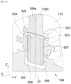
Fig. 4 , le cylindre extérieur 504 est creux et l'attache moteur avant 160 comporte également un cylindre intérieur 505 qui est inséré et fixé dans le cylindre extérieur 504. Le cylindre intérieur 505 est donc également coaxial avec l'axe vertical 20. Le diamètre extérieur du cylindre intérieur 505 est inférieur au diamètre intérieur du cylindre extérieur 504 pour créer un espace 507 entre eux, c'est-à-dire entre l'intérieur du cylindre extérieur 504 et l'extérieur du cylindre intérieur 505. La différence de diamètre est par exemple de l'ordre de 0,6 mm à 2 mm et préférentiellement de 1 mm. - Dans le mode de réalisation de l'invention présenté à la
Fig. 4 , la première extrémité du cylindre extérieur 504 et le cylindre intérieur 505 sont fixés par mise en place d'une goupille 503 qui est enchâssée dans un alésage qui travers le cylindre extérieur 504, le cylindre intérieur 505 et le nez 110. L'axe de la goupille 503 est ici perpendiculaire à l'axe vertical 20. Dans le mode de réalisation de l'invention présenté à laFig. 5 , il y a uniquement le cylindre extérieure 504 qui est ici plein. - La chape femelle principale 111 est disposée à l'avant de la liaison spigot 169 par rapport à la direction longitudinale X, c'est-à-dire que l'axe principal 10 de la liaison rotule principale est à l'avant de l'axe vertical 20.
- Avec un tel arrangement, le mât 104 incorpore directement les éléments assurant la fixation du moteur 102 pour diminuer la hauteur nécessaire à cette fixation.
- Lorsque le moteur 102 est en fonctionnement, des efforts sont générés et ils sont transmis à la structure de l'aile à travers le carter avant 103 et le système d'attache moteur avant 150, c'est-à-dire à travers la bielle principale 162, l'arbre secondaire 167, l'arbre principal 165, la liaison spigot 169 et le mât réacteur 104 qui forment un chemin primaire d'efforts.
- Les efforts en Z sont ainsi transmis à travers la liaison rotule secondaire et la liaison rotule principale, c'est-à-dire verticalement à travers la bielle principale 162.
- Les efforts en X et en Y sont transmis à travers la liaison spigot 169.
- Pour des raisons de sécurité, le système d'attache moteur avant 150 comporte également des moyens qui assurent des chemins secondaires d'efforts qui compensent une défaillance du chemin primaire d'efforts, ces moyens constituant des moyens de sécurité en attente (dit « waiting fail-safe » en langue anglo-saxonne).
- Dans le mode de réalisation de l'invention présenté à la
Fig. 5 , en cas de défaillance au niveau au niveau de la liaison spigot 169, il est nécessaire de continuer à transmettre les efforts en Y. Ainsi, selon un mode de réalisation particulier de l'invention, le nez 110 comporte alors deux butées latérales 512a-b qui sont disposées respectivement à bâbord et à tribord du cylindre extérieur 504 et, pour chaque butée latérale 512a-b, le carter avant 103 comporte une contre-butée latérale 510a-b et les deux contre-butées latérales 510a-b sont également disposées respectivement à bâbord et à tribord du cylindre extérieur 504 et les butées latérales 512a-b sont disposées entre les contre-butées latérales 510a-b. - En position normale, c'est-à-dire sans défaillance du chemin primaire d'efforts, chaque butée latérale 512a-b est à distance de la contre-butée latérale 510a-b associée, et en cas de défaillance, l'une des butées latérales 512a-b vient en appui contre la contre-butée latérale 510a-b associée.
- Dans le mode de réalisation de l'invention présenté à la
Fig. 4 , en cas de rupture au niveau du cylindre extérieur 504, le cylindre intérieur 505 prend le relais et forme ainsi un moyen de sécurité en attente (dit « waiting fail-safe » en langue anglo-saxonne). - En cas de défaillance, il est nécessaire de continuer à transmettre les efforts en Z. Ainsi, selon un mode de réalisation particulier de l'invention, le système d'attache moteur avant 150 comporte deux bielles latérales 170a-b disposées respectivement à bâbord et à tribord de la bielle principale 162, et dans le mode de réalisation de l'invention présenté aux
Figs. 2 et3 , respectivement à bâbord et à tribord des parois 110a-b formant la chape femelle principale 111 et symétriquement par rapport au plan médian XZ. - Chaque bielle latérale 170a-b est montée sur l'arbre principal 165 avec un ajustement serré et sur l'arbre secondaire 167 avec jeu. Ainsi, dans certains cas de défaillance, au moins une bielle latérale 170a-b et/ou l'arbre secondaire 167 vont se déplacer pour amener la paroi intérieure de l'alésage de ladite au moins une bielle latérale 170a-b contre l'arbre secondaire 167.
- Dans le mode de réalisation de l'invention présenté aux
Figs. 2 et3 , l'arbre principal 165 est constitué d'un arbre périphérique 165a qui est cylindrique et creux et d'un arbre intérieur 165b qui est logé dans l'arbre périphérique 165a. Un tel arrangement permet de compenser une éventuelle rupture de l'arbre périphérique 165a. - Dans le mode de réalisation de l'invention présenté aux
Figs. 2 et3 , l'arbre secondaire 167 est constitué d'un arbre périphérique 167a qui est cylindrique et creux et d'un arbre intérieur 167b qui est logé dans l'arbre périphérique 167a. Un tel arrangement permet de compenser une éventuelle rupture de l'arbre périphérique 167a.
Claims (8)
- Système d'attache moteur avant (150) pour un moteur (102) d'un aéronef (100), le système d'attache moteur avant (150) présentant un plan médian vertical (XZ) et comportant :- un mât réacteur (104) comportant au niveau d'une partie avant, un nez (110) présentant une chape femelle principale (111) et un logement cylindrique (502) autour d'un axe vertical (20),- une bielle principale (162) destinée à être fixée à un carter avant (103) du moteur (102) par une liaison rotule secondaire autour d'un axe secondaire (12) perpendiculaire au plan médian (XZ) par l'intermédiaire d'un arbre secondaire (167),- un arbre principal (165) perpendiculaire au plan médian (XZ) et réalisant une liaison rotule principale de la bielle principale (162) dans la chape femelle principale (111) autour d'un axe principal (10), où l'axe principal (10) et l'axe secondaire (12) sont dans un même plan vertical perpendiculaire au plan médian (XZ), et- un cylindre extérieur (504) coaxial avec l'axe vertical (20), dont une première extrémité est fixée dans le logement cylindrique (502) et dont une deuxième extrémité est destinée à être montée mobile au travers d'une liaison linéaire annulaire autour de l'axe vertical (20) par rapport au carter avant (103).
- Système d'attache moteur avant (150) selon la revendication 1, caractérisé en ce que l'axe principal (10) est disposé à l'avant de l'axe vertical (20).
- Système d'attache moteur avant (150) selon l'une des revendications 1 ou 2, caractérisé en ce qu'il comporte un cylindre intérieur (505) inséré et fixé dans le cylindre extérieur (504).
- Système d'attache moteur avant (150) selon l'une des revendications 1 ou 2, caractérisé en ce que le nez (110) comporte deux butées latérales (512a-b) disposées respectivement à bâbord et à tribord du cylindre extérieur (504) et qui sont destinées à venir entre deux contre-butées latérales (510a-b) du carter avant (103).
- Système d'attache moteur avant (150) selon l'une des revendications 1 à 4, caractérisé en ce qu'il comporte deux bielles latérales (170a-b) disposées respectivement à bâbord et à tribord de la bielle principale (162), et en ce que chaque bielle latérale (170a-b) est montée sur l'arbre principal (165) avec un ajustement serré et sur l'arbre secondaire (167) avec jeu.
- Système d'attache moteur avant (150) selon l'une des revendications 1 à 5, caractérisé en ce que l'arbre principal (165) est constitué d'un arbre périphérique (165a) qui est creux et d'un arbre intérieur (165b) qui est logé dans l'arbre périphérique (165a).
- Système d'attache moteur avant (150) selon l'une des revendications 1 à 6, caractérisé en ce que l'arbre secondaire (167) est constitué d'un arbre périphérique (167a) qui est creux et d'un arbre intérieur (167b) qui est logé dans l'arbre périphérique (167a).
- Aéronef (100) comportant une structure, un moteur (102) avec un carter avant (103) et un système d'attache moteur avant (150) selon l'une des revendications précédentes, où la bielle principale (162) est fixée au carter avant (103) par la liaison rotule secondaire et où la deuxième extrémité du cylindre extérieur (504) est montée mobile au travers de la liaison linéaire annulaire autour de l'axe vertical (20) par rapport au carter avant (103).
Applications Claiming Priority (1)
| Application Number | Priority Date | Filing Date | Title |
|---|---|---|---|
| FR2306784A FR3150504A1 (fr) | 2023-06-28 | 2023-06-28 | Système d’attache moteur avant pour un moteur d’aéronef qui comporte une structure compacte |
Publications (2)
| Publication Number | Publication Date |
|---|---|
| EP4484298A1 true EP4484298A1 (fr) | 2025-01-01 |
| EP4484298B1 EP4484298B1 (fr) | 2026-03-18 |
Family
ID=88412986
Family Applications (1)
| Application Number | Title | Priority Date | Filing Date |
|---|---|---|---|
| EP24184546.0A Active EP4484298B1 (fr) | 2023-06-28 | 2024-06-26 | Système d attache moteur avant pour un moteur d aéronef qui comporte une structure compacte |
Country Status (4)
| Country | Link |
|---|---|
| US (1) | US12539974B2 (fr) |
| EP (1) | EP4484298B1 (fr) |
| CN (1) | CN119222046A (fr) |
| FR (1) | FR3150504A1 (fr) |
Cited By (1)
| Publication number | Priority date | Publication date | Assignee | Title |
|---|---|---|---|---|
| EP4786335A1 (fr) | 2025-02-04 | 2026-08-05 | Airbus Operations (S.A.S.) | Système de propulsion pour aéronef comportant un mât réacteur, un turboréacteur et des moyens de fixation du turboréacteur au mât |
Families Citing this family (3)
| Publication number | Priority date | Publication date | Assignee | Title |
|---|---|---|---|---|
| EP4491518B1 (fr) * | 2023-07-10 | 2026-02-25 | Airbus Operations (S.A.S.) | Ensemble propulseur d'aéronef comprenant une bielle principale d'attache moteur, ainsi que deux bielles de sécurité en parallèle, reliées à un renfort transversal avant d'une structure primaire d'un mât |
| FR3156756A1 (fr) * | 2023-12-14 | 2025-06-20 | Airbus Operations | Ensemble propulsif pour aéronef comportant un moteur, un mât et des moyens d’accrochage du moteur au mât |
| EP4574669A1 (fr) * | 2023-12-22 | 2025-06-25 | Airbus Operations (S.A.S.) | Assemblage d'un mât d'accrochage avec un moteur d'aéronef |
Citations (6)
| Publication number | Priority date | Publication date | Assignee | Title |
|---|---|---|---|---|
| GB2119857A (en) * | 1982-04-30 | 1983-11-23 | Rolls Royce | Ducted fan gas turbine engine |
| WO1993011041A1 (fr) * | 1991-11-25 | 1993-06-10 | Rolls-Royce Plc | Agencement de montage pour un turbo-moteur a combustion |
| EP1814783B1 (fr) * | 2004-11-23 | 2008-05-21 | AIRBUS France | Systeme de fixation d'un mat de moteur a l'aile d'un aeronef |
| FR3098793A1 (fr) * | 2019-07-17 | 2021-01-22 | Airbus Operations (S.A.S.) | Ensemble propulseur comprenant une attache moteur avant améliorée et aéronef comprenant au moins un tel ensemble propulseur |
| FR3103788A1 (fr) * | 2019-11-28 | 2021-06-04 | Airbus Operations | Ensemble pour un aeronef, ledit ensemble comportant un mat, une aile et un systeme de fixation entre le mat et l’aile |
| EP3945032A1 (fr) * | 2020-07-31 | 2022-02-02 | Airbus Operations (S.A.S.) | Assemblage d'un mat avec une aile d'aeronef |
Family Cites Families (4)
| Publication number | Priority date | Publication date | Assignee | Title |
|---|---|---|---|---|
| FR3096028B1 (fr) * | 2019-05-14 | 2021-05-21 | Airbus Operations Sas | Attache moteur arriere pour un moteur d’aeronef |
| US11273923B2 (en) * | 2019-07-12 | 2022-03-15 | Spirit Aerosystems, Inc. | Fail-safe engine support system |
| FR3124164A1 (fr) * | 2021-06-30 | 2022-12-23 | Airbus Operations | Manille de fixation d’un moteur d’aeronef comprenant un couple de revetements antifriction encapsules, et aeronef comprenant une telle manille. |
| FR3150505A1 (fr) * | 2023-06-28 | 2025-01-03 | Airbus Operations | Système d’attache moteur avant pour un moteur d’aéronef qui comporte une structure compacte |
-
2023
- 2023-06-28 FR FR2306784A patent/FR3150504A1/fr not_active Ceased
-
2024
- 2024-06-26 US US18/755,108 patent/US12539974B2/en active Active
- 2024-06-26 EP EP24184546.0A patent/EP4484298B1/fr active Active
- 2024-06-27 CN CN202410845513.6A patent/CN119222046A/zh active Pending
Patent Citations (6)
| Publication number | Priority date | Publication date | Assignee | Title |
|---|---|---|---|---|
| GB2119857A (en) * | 1982-04-30 | 1983-11-23 | Rolls Royce | Ducted fan gas turbine engine |
| WO1993011041A1 (fr) * | 1991-11-25 | 1993-06-10 | Rolls-Royce Plc | Agencement de montage pour un turbo-moteur a combustion |
| EP1814783B1 (fr) * | 2004-11-23 | 2008-05-21 | AIRBUS France | Systeme de fixation d'un mat de moteur a l'aile d'un aeronef |
| FR3098793A1 (fr) * | 2019-07-17 | 2021-01-22 | Airbus Operations (S.A.S.) | Ensemble propulseur comprenant une attache moteur avant améliorée et aéronef comprenant au moins un tel ensemble propulseur |
| FR3103788A1 (fr) * | 2019-11-28 | 2021-06-04 | Airbus Operations | Ensemble pour un aeronef, ledit ensemble comportant un mat, une aile et un systeme de fixation entre le mat et l’aile |
| EP3945032A1 (fr) * | 2020-07-31 | 2022-02-02 | Airbus Operations (S.A.S.) | Assemblage d'un mat avec une aile d'aeronef |
Cited By (2)
| Publication number | Priority date | Publication date | Assignee | Title |
|---|---|---|---|---|
| EP4786335A1 (fr) | 2025-02-04 | 2026-08-05 | Airbus Operations (S.A.S.) | Système de propulsion pour aéronef comportant un mât réacteur, un turboréacteur et des moyens de fixation du turboréacteur au mât |
| FR3171845A1 (fr) * | 2025-02-04 | 2026-08-07 | Airbus Operations (S.A.S.) | Système de propulsion pour aéronef comportant un mât réacteur, un turboréacteur et des moyens de fixation du turboréacteur au mât réacteur |
Also Published As
| Publication number | Publication date |
|---|---|
| EP4484298B1 (fr) | 2026-03-18 |
| US20250002164A1 (en) | 2025-01-02 |
| FR3150504A1 (fr) | 2025-01-03 |
| CN119222046A (zh) | 2024-12-31 |
| US12539974B2 (en) | 2026-02-03 |
Similar Documents
| Publication | Publication Date | Title |
|---|---|---|
| EP4484297B1 (fr) | Système d'attache moteur avant pour un moteur d'aéronef qui comporte une structure compacte | |
| EP4484298B1 (fr) | Système d attache moteur avant pour un moteur d aéronef qui comporte une structure compacte | |
| EP3483069B1 (fr) | Systeme d'attache moteur d'aeronef | |
| EP2139768B1 (fr) | Mat d'accrochage de moteur pour aeronef disposant d'une attache moteur arriere pourvue d'un ecrou a barillet | |
| FR3068008B1 (fr) | Ensemble de motorisation pour un aeronef | |
| WO2021104913A1 (fr) | Systeme d'attache moteur avant pour un moteur aéronef qui comporte une structure allégée | |
| EP4144647B1 (fr) | Système d'attache moteur avant pour un moteur d'aéronef qui comporte une structure compacte | |
| EP4484299A1 (fr) | Système d attache moteur avant pour un moteur d aéronef qui comporte une structure compacte | |
| EP1231138A1 (fr) | Dispositif d'accrochage d'un moteur sur un aéronef | |
| EP3486174B1 (fr) | Attache moteur arriere pour un moteur d'aeronef | |
| FR3073205A1 (fr) | Attache moteur d'un moteur d'aeronef | |
| FR2873985A1 (fr) | Ensemble moteur pour aeronef | |
| FR3058986A1 (fr) | Attache arriere d'un moteur d'aeronef comportant des temoins de rupture | |
| FR2873986A1 (fr) | Ensemble moteur pour aeronef | |
| EP4124575A1 (fr) | Ensemble propulsif pour aéronef comportant un turboréacteur, un mât et des moyens d accrochage du turboréacteur au mât | |
| FR3156756A1 (fr) | Ensemble propulsif pour aéronef comportant un moteur, un mât et des moyens d’accrochage du moteur au mât | |
| FR3149869A1 (fr) | Dispositif pour coupler un système de propulsion à un mât reacteur d’un aeronef et aeronef correspondant | |
| FR3103788A1 (fr) | Ensemble pour un aeronef, ledit ensemble comportant un mat, une aile et un systeme de fixation entre le mat et l’aile | |
| EP4488178B1 (fr) | Assemblage d'un mât d'accrochage avec un moteur d'aéronef | |
| EP3728039B1 (fr) | Dispositif de suspension | |
| EP4491518A1 (fr) | Ensemble propulseur d'aéronef comprenant une bielle principale d'attache moteur, ainsi que deux bielles de sécurité en parallèle, reliées à un renfort transversal avant d'une structure primaire d'un mât | |
| FR3131734A1 (fr) | Ensemble propulsif pour aéronef comportant un turboréacteur, un mât et des moyens d’accrochage du turboréacteur au mât | |
| FR3095192A1 (fr) | Systeme d’attache moteur pour un moteur d’aeronef | |
| EP4450397B1 (fr) | Ensemble pour la fixation de poutres comportant une plaque support et deux ferrures de part et d'autre de la plaque support | |
| FR3156118A1 (fr) | Mât réacteur pour le montage sur un aéronef d’un système de propulsion |
Legal Events
| Date | Code | Title | Description |
|---|---|---|---|
| PUAI | Public reference made under article 153(3) epc to a published international application that has entered the european phase |
Free format text: ORIGINAL CODE: 0009012 |
|
| STAA | Information on the status of an ep patent application or granted ep patent |
Free format text: STATUS: THE APPLICATION HAS BEEN PUBLISHED |
|
| AK | Designated contracting states |
Kind code of ref document: A1 Designated state(s): AL AT BE BG CH CY CZ DE DK EE ES FI FR GB GR HR HU IE IS IT LI LT LU LV MC ME MK MT NL NO PL PT RO RS SE SI SK SM TR |
|
| STAA | Information on the status of an ep patent application or granted ep patent |
Free format text: STATUS: REQUEST FOR EXAMINATION WAS MADE |
|
| 17P | Request for examination filed |
Effective date: 20250610 |
|
| GRAP | Despatch of communication of intention to grant a patent |
Free format text: ORIGINAL CODE: EPIDOSNIGR1 |
|
| STAA | Information on the status of an ep patent application or granted ep patent |
Free format text: STATUS: GRANT OF PATENT IS INTENDED |
|
| INTG | Intention to grant announced |
Effective date: 20251014 |
|
| GRAS | Grant fee paid |
Free format text: ORIGINAL CODE: EPIDOSNIGR3 |
|
| GRAA | (expected) grant |
Free format text: ORIGINAL CODE: 0009210 |
|
| STAA | Information on the status of an ep patent application or granted ep patent |
Free format text: STATUS: THE PATENT HAS BEEN GRANTED |
|
| AK | Designated contracting states |
Kind code of ref document: B1 Designated state(s): AL AT BE BG CH CY CZ DE DK EE ES FI FR GB GR HR HU IE IS IT LI LT LU LV MC ME MK MT NL NO PL PT RO RS SE SI SK SM TR |
|
| REG | Reference to a national code |
Ref country code: CH Ref legal event code: F10 Free format text: ST27 STATUS EVENT CODE: U-0-0-F10-F00 (AS PROVIDED BY THE NATIONAL OFFICE) Effective date: 20260318 Ref country code: GB Ref legal event code: FG4D Free format text: NOT ENGLISH |
|
| REG | Reference to a national code |
Ref country code: IE Ref legal event code: FG4D Free format text: LANGUAGE OF EP DOCUMENT: FRENCH |
|
| REG | Reference to a national code |
Ref country code: DE Ref legal event code: R096 Ref document number: 602024003243 Country of ref document: DE |
|
| PG25 | Lapsed in a contracting state [announced via postgrant information from national office to epo] |
Ref country code: RS Free format text: LAPSE BECAUSE OF FAILURE TO SUBMIT A TRANSLATION OF THE DESCRIPTION OR TO PAY THE FEE WITHIN THE PRESCRIBED TIME-LIMIT Effective date: 20260618 |
|
| PG25 | Lapsed in a contracting state [announced via postgrant information from national office to epo] |
Ref country code: GR Free format text: LAPSE BECAUSE OF FAILURE TO SUBMIT A TRANSLATION OF THE DESCRIPTION OR TO PAY THE FEE WITHIN THE PRESCRIBED TIME-LIMIT Effective date: 20260619 |
|
| REG | Reference to a national code |
Ref country code: LT Ref legal event code: MG9D |
|
| PG25 | Lapsed in a contracting state [announced via postgrant information from national office to epo] |
Ref country code: LT Free format text: LAPSE BECAUSE OF FAILURE TO SUBMIT A TRANSLATION OF THE DESCRIPTION OR TO PAY THE FEE WITHIN THE PRESCRIBED TIME-LIMIT Effective date: 20260318 |
|
| PGFP | Annual fee paid to national office [announced via postgrant information from national office to epo] |
Ref country code: DE Payment date: 20260622 Year of fee payment: 3 |
|
| PG25 | Lapsed in a contracting state [announced via postgrant information from national office to epo] |
Ref country code: NO Free format text: LAPSE BECAUSE OF FAILURE TO SUBMIT A TRANSLATION OF THE DESCRIPTION OR TO PAY THE FEE WITHIN THE PRESCRIBED TIME-LIMIT Effective date: 20260618 |
|
| PG25 | Lapsed in a contracting state [announced via postgrant information from national office to epo] |
Ref country code: SE Free format text: LAPSE BECAUSE OF FAILURE TO SUBMIT A TRANSLATION OF THE DESCRIPTION OR TO PAY THE FEE WITHIN THE PRESCRIBED TIME-LIMIT Effective date: 20260318 Ref country code: FI Free format text: LAPSE BECAUSE OF FAILURE TO SUBMIT A TRANSLATION OF THE DESCRIPTION OR TO PAY THE FEE WITHIN THE PRESCRIBED TIME-LIMIT Effective date: 20260318 |
|
| PG25 | Lapsed in a contracting state [announced via postgrant information from national office to epo] |
Ref country code: HR Free format text: LAPSE BECAUSE OF FAILURE TO SUBMIT A TRANSLATION OF THE DESCRIPTION OR TO PAY THE FEE WITHIN THE PRESCRIBED TIME-LIMIT Effective date: 20260318 |
|
| REG | Reference to a national code |
Ref country code: NL Ref legal event code: MP Effective date: 20260318 |
|
| PGFP | Annual fee paid to national office [announced via postgrant information from national office to epo] |
Ref country code: FR Payment date: 20260626 Year of fee payment: 3 |
|
| PG25 | Lapsed in a contracting state [announced via postgrant information from national office to epo] |
Ref country code: LV Free format text: LAPSE BECAUSE OF FAILURE TO SUBMIT A TRANSLATION OF THE DESCRIPTION OR TO PAY THE FEE WITHIN THE PRESCRIBED TIME-LIMIT Effective date: 20260318 |
|
| PG25 | Lapsed in a contracting state [announced via postgrant information from national office to epo] |
Ref country code: BG Free format text: LAPSE BECAUSE OF FAILURE TO SUBMIT A TRANSLATION OF THE DESCRIPTION OR TO PAY THE FEE WITHIN THE PRESCRIBED TIME-LIMIT Effective date: 20260318 |