EP4484232A1 - Braking device for vehicles - Google Patents
Braking device for vehicles Download PDFInfo
- Publication number
- EP4484232A1 EP4484232A1 EP24167015.7A EP24167015A EP4484232A1 EP 4484232 A1 EP4484232 A1 EP 4484232A1 EP 24167015 A EP24167015 A EP 24167015A EP 4484232 A1 EP4484232 A1 EP 4484232A1
- Authority
- EP
- European Patent Office
- Prior art keywords
- braking
- tank
- fact
- port
- chamber
- Prior art date
- Legal status (The legal status is an assumption and is not a legal conclusion. Google has not performed a legal analysis and makes no representation as to the accuracy of the status listed.)
- Granted
Links
Images



Classifications
-
- B—PERFORMING OPERATIONS; TRANSPORTING
- B60—VEHICLES IN GENERAL
- B60T—VEHICLE BRAKE CONTROL SYSTEMS OR PARTS THEREOF; BRAKE CONTROL SYSTEMS OR PARTS THEREOF, IN GENERAL; ARRANGEMENT OF BRAKING ELEMENTS ON VEHICLES IN GENERAL; PORTABLE DEVICES FOR PREVENTING UNWANTED MOVEMENT OF VEHICLES; VEHICLE MODIFICATIONS TO FACILITATE COOLING OF BRAKES
- B60T11/00—Transmitting braking action from initiating means to ultimate brake actuator without power assistance or drive or where such assistance or drive is irrelevant
- B60T11/10—Transmitting braking action from initiating means to ultimate brake actuator without power assistance or drive or where such assistance or drive is irrelevant transmitting by fluid means, e.g. hydraulic
- B60T11/16—Master control, e.g. master cylinders
- B60T11/232—Recuperation valves
-
- B—PERFORMING OPERATIONS; TRANSPORTING
- B60—VEHICLES IN GENERAL
- B60T—VEHICLE BRAKE CONTROL SYSTEMS OR PARTS THEREOF; BRAKE CONTROL SYSTEMS OR PARTS THEREOF, IN GENERAL; ARRANGEMENT OF BRAKING ELEMENTS ON VEHICLES IN GENERAL; PORTABLE DEVICES FOR PREVENTING UNWANTED MOVEMENT OF VEHICLES; VEHICLE MODIFICATIONS TO FACILITATE COOLING OF BRAKES
- B60T11/00—Transmitting braking action from initiating means to ultimate brake actuator without power assistance or drive or where such assistance or drive is irrelevant
- B60T11/10—Transmitting braking action from initiating means to ultimate brake actuator without power assistance or drive or where such assistance or drive is irrelevant transmitting by fluid means, e.g. hydraulic
- B60T11/26—Reservoirs
-
- B—PERFORMING OPERATIONS; TRANSPORTING
- B60—VEHICLES IN GENERAL
- B60T—VEHICLE BRAKE CONTROL SYSTEMS OR PARTS THEREOF; BRAKE CONTROL SYSTEMS OR PARTS THEREOF, IN GENERAL; ARRANGEMENT OF BRAKING ELEMENTS ON VEHICLES IN GENERAL; PORTABLE DEVICES FOR PREVENTING UNWANTED MOVEMENT OF VEHICLES; VEHICLE MODIFICATIONS TO FACILITATE COOLING OF BRAKES
- B60T13/00—Transmitting braking action from initiating means to ultimate brake actuator with power assistance or drive; Brake systems incorporating such transmitting means, e.g. air-pressure brake systems
- B60T13/10—Transmitting braking action from initiating means to ultimate brake actuator with power assistance or drive; Brake systems incorporating such transmitting means, e.g. air-pressure brake systems with fluid assistance, drive, or release
- B60T13/66—Electrical control in fluid-pressure brake systems
- B60T13/662—Electrical control in fluid-pressure brake systems characterised by specified functions of the control system components
-
- B—PERFORMING OPERATIONS; TRANSPORTING
- B60—VEHICLES IN GENERAL
- B60T—VEHICLE BRAKE CONTROL SYSTEMS OR PARTS THEREOF; BRAKE CONTROL SYSTEMS OR PARTS THEREOF, IN GENERAL; ARRANGEMENT OF BRAKING ELEMENTS ON VEHICLES IN GENERAL; PORTABLE DEVICES FOR PREVENTING UNWANTED MOVEMENT OF VEHICLES; VEHICLE MODIFICATIONS TO FACILITATE COOLING OF BRAKES
- B60T13/00—Transmitting braking action from initiating means to ultimate brake actuator with power assistance or drive; Brake systems incorporating such transmitting means, e.g. air-pressure brake systems
- B60T13/10—Transmitting braking action from initiating means to ultimate brake actuator with power assistance or drive; Brake systems incorporating such transmitting means, e.g. air-pressure brake systems with fluid assistance, drive, or release
- B60T13/66—Electrical control in fluid-pressure brake systems
- B60T13/68—Electrical control in fluid-pressure brake systems by electrically-controlled valves
- B60T13/686—Electrical control in fluid-pressure brake systems by electrically-controlled valves in hydraulic systems or parts thereof
-
- B—PERFORMING OPERATIONS; TRANSPORTING
- B60—VEHICLES IN GENERAL
- B60T—VEHICLE BRAKE CONTROL SYSTEMS OR PARTS THEREOF; BRAKE CONTROL SYSTEMS OR PARTS THEREOF, IN GENERAL; ARRANGEMENT OF BRAKING ELEMENTS ON VEHICLES IN GENERAL; PORTABLE DEVICES FOR PREVENTING UNWANTED MOVEMENT OF VEHICLES; VEHICLE MODIFICATIONS TO FACILITATE COOLING OF BRAKES
- B60T17/00—Component parts, details, or accessories of power brake systems not covered by groups B60T8/00, B60T13/00 or B60T15/00, or presenting other characteristic features
- B60T17/18—Safety devices; Monitoring
- B60T17/22—Devices for monitoring or checking brake systems; Signal devices
- B60T17/221—Procedure or apparatus for checking or keeping in a correct functioning condition of brake systems
- B60T17/222—Procedure or apparatus for checking or keeping in a correct functioning condition of brake systems by filling or bleeding of hydraulic systems
Definitions
- the present invention relates to a braking device for vehicles, particularly to a secondary braking valve.
- Braking circuits generally used in vehicles and particularly in tractors and operating machinery comprise a main braking device (typically of the master cylinder type) connected to the brake pedal and adapted to send pressurized oil to the braking circuit as a result of the pressure exerted on the pedal itself, so as to brake the vehicle.
- a main braking device typically of the master cylinder type
- a braking pump operates as main braking device and isolates the oil within a collection tank and then transfers it, as a result of the brake pedal actuation, to the braking circuit.
- Braking circuits of known type may also have a secondary braking valve, adapted to operate in parallel with the main braking device in order to assist the braking action controlled by the latter.
- the secondary braking valve is then also connected to the vehicle braking circuit and can be controlled electronically.
- both the main braking device and the secondary braking valve are provided with a relevant braking piston housed sliding within a relevant braking chamber, where the stroke of the braking piston determines the amount of oil sent to the braking circuit and, consequently, the intensity and effectiveness of the braking action.
- the main aim of the present invention is to devise a braking device for vehicles, and in particular a secondary braking valve, which makes it possible to eliminate or at least reduce the risk that any air bubbles contained in the braking liquid may enter the relevant braking chamber, thus adversely affecting the effectiveness of the braking action.
- Another object of the present invention is to devise a braking device for vehicles which allows the aforementioned drawbacks of the prior art to be overcome within the framework of a simple, rational, easy and effective to use as well as cost-effective solution.
- reference numeral 1 globally denotes a braking device for vehicles, particularly a secondary braking valve.
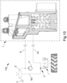
- FIG 10 shows a braking circuit 100 within which the braking device 1 is inserted.
- the circuit 100 comprises a main braking device D which can be connected to the brake pedal F of a vehicle and a hydraulic pump P connected to the braking device 1.
- the pump P can also be connected, as in the embodiment shown in Figure 10 , to the main braking device D.
- the braking circuit 100 comprises a feeding channel A adapted to set the pump P in communication with the braking device 1 and, possibly, with the main braking device D, a first braking channel N1 adapted to set the device 1 in communication with the braking circuit I and a second braking channel N2 adapted to set the main braking device D in communication with the braking circuit I.
- valve means V e.g. of the type of a so-called “shuttle valve", adapted to selectively set the braking circuit I in communication with that of either the first braking channel N1 or the second braking channel N2 having higher pressure.
- the device 1 comprises a body 2 provided with at least one inlet port 3 of a pressurized working liquid, e.g., oil, with at least one outlet port 4 connectable to the braking circuit I of a vehicle, and with at least one draining port 5 connectable to a draining tank.
- a pressurized working liquid e.g., oil
- the inlet port 3 is connectable to the pump P and the outlet port 4 is connectable to the second braking channel N2 of the circuit 100.
- the device 1 then comprises a first tank 6 provided with an inlet spout 26 of the working liquid and open at the top to define a first upper port 6a, and a second tank 7 communicating with the first tank 6.
- the first tank 6 and the second tank 7 are arranged side by side.
- the first tank 6 and the second tank 7 are defined within the body 2. There is then a closing element 9, e.g. of the type of a lid, of at least the first upper port 6a.
- the closing element 9 is arranged, in use, (where this definition means the position taken by the device 1 during its use), inclined with respect to the horizon.
- the second tank 7 is also open at the top to define a second upper port 7a, and the closing element 9 is arranged raised above the upper ports 6a, 7a so as to define a connecting channel 10 between the first tank 6 and the second tank 7.
- the second tank 7 is closed at the top by the same body 2.
- the draining port 5 is defined on the closing element 9 and is arranged facing the first upper port 6a.
- the closing element 9 is inclined from top to bottom proceeding from the first tank 6 towards the second tank 7.
- the height of the closing element 9 with respect to a horizontal reference plane turns out to be greater where the first tank 6 is located than that measured where the second tank 7 is located.
- the device 1 also comprises at least one working chamber 11 provided with at least one connecting port 12 to the second tank 7 and within which at least one braking piston 13,14 is housed sealing in a sliding manner, which divides the working chamber 11 into at least one driving chamber 11a connectable to the inlet port 3 and a braking chamber 11b communicating with the outlet port 4 and with the connecting port 12.
- the device 1 comprises at least one filtering element 8 located between the inlet spout 26 and the connecting port 12, which is adapted to allow the passage of the working liquid and to retain the air bubbles contained therein.
- the filtering element 8 is arranged facing the first upper port 6a.
- the draining port 5 defined on the closing element 9 is arranged facing the filtering element 8.
- the filtering element 8 is arranged within at least one of either the first tank 6 or the second tank 7. Further embodiments cannot however be ruled out wherein the filtering element 8 is arranged both where the first port 6a is located and within at least one of the tanks 6 and 7.
- the filtering element 8 can be of the slab-shaped type (as in the embodiment shown in the figures), e.g. of the type of a wire mesh, or it can define a closed profile having, e.g., a cylindrical conformation.
- the working chamber 11 has a bottom wall 11c and a top 11d opposite each other.
- the connecting port 12 is defined where the top 11d is located.
- the braking chamber 11b is obtained within the body 2 and is arranged, in use, below the second tank 7.
- the volume of the second tank 7 is greater than the maximum volume of the braking chamber 11b. This ensures that the working liquid contained in the second tank 7 can never flow completely into the braking chamber 11b, thus preventing any air bubbles contained in the second tank itself, which collect at the free surface of the liquid contained within it, from being transferred into the braking chamber 11b.
- At least one plug element 15 is housed inside the working chamber 11 and is connected to the braking piston 13,14 in a kinematic manner and adapted to open/close the connecting port 12. In other words, the displacement of the plug element 15 is affected by the movement of the braking piston 13,14.
- the braking piston 13,14 comprises at least one tumbler element 13 and at least one driving element 14 inserted passing through the tumbler element itself and connected to the plug element 15 in a kinematic manner.
- the driving element 14 is inserted tightly in a sliding manner within the tumbler element 13.
- the tumbler element 13 is movable by shifting within the working chamber 11 between a home position, wherein it rests against the bottom wall 11c of the working chamber itself, and at least one braking position, wherein it is raised with respect to the bottom wall 11c. It follows that the greater the distance of the tumbler element 13 from the bottom wall 11c, the greater the volume of the working liquid transferred towards the braking circuit I.
- first elastic means 16 which are adapted to push the tumbler element 13 towards the home position.
- first elastic means 16 are adapted to counteract the displacement of the tumbler element 13 towards the braking position.
- the tumbler element 13 defines a housing seat 13a of the first elastic means 16 which have one end associated with the tumbler element itself and the opposite end operating on the top 11d of the braking chamber 11b.
- the first elastic means 16 are, e.g., of the type of a coil spring.
- the upper portion of the first elastic means 16 is fitted around a spring-guiding element 17 that rests against the top 11d of the working chamber 11. More specifically, the spring-guiding element 17 can be separate from the body 2 or, alternatively, made in a single piece therewith.
- the driving element 14 also faces the bottom wall 11c and moves locked together with the tumbler element 13 during a first stretch of its travel from the home position towards a braking position.
- the tumbler element 13 has at least a first abutment surface 18 adapted to interact with the driving element 14 during the displacement from a braking position towards the home position to drag the driving element itself towards the bottom wall 11c.
- the driving element 14 comprises at least one stopping surface 19, defined e.g. by a Seeger ring, which is adapted to interact with the spring-guiding element 17 during its displacement away from the bottom wall 11c.
- the stroke of the driving element 14 away from the bottom wall 11c is limited with respect to that of the tumbler element 13, so that the maximum load that the driving element itself can apply to the plug element 15 to which it is kinematically connected is reduced.
- the second elastic means 20 are located between the driving element 14 and the plug element 15, which are adapted to push the plug element itself towards the connecting port 12 as a result of the displacement of the driving element 14 away from the bottom wall 11c.
- the second elastic means 20 in turn push the plug element 15 towards the closing position of the connecting port 12.
- the equivalent pressure exerted by the first elastic means 16 on the tumbler element 13 is greater than that exerted by the second elastic means 20 on the plug element 15.
- the driving element 14 has a second abutment surface 21 adapted to interact with the plug element 15 during its displacement towards the bottom wall 11c so as to drag it away from the connecting port 12.
- the device 1 comprises valve means 22 adapted to set the driving chamber 11a in communication with the inlet port 3 and/or with the first tank 6.
- valve means 22 are movable between two extreme working positions where, in the first working position, the inlet port 3 is closed and the driving chamber 11a is set in communication with the inlet spout 26 while, in the second working position, the inlet port 3 is set in communication with the driving chamber 11a and the connection with the first tank 6 is closed.
- the braking piston 13,14 is arranged resting against the bottom wall of the working chamber 11, the driving chamber 11a is set in communication with the first tank 6 through the valve means 22 and the braking chamber 11b is set in communication with the second tank 7 through the connecting port 12, which is opened by the plug element 15.
- the driving chamber 11a is set under pressure as a result of the inlet of the working liquid coming from the inlet port 3.
- the braking piston 13,14 is raised with respect to the bottom wall 11c. More specifically, both the tumbler element 13 and the driving element 14 are raised with respect to the bottom wall 11c, where the tumbler element 13 begins to compress the first elastic means 16 and the driving element 14 exerts a pushing action on the plug element 15, by means of the second elastic means 20, causing the connecting port 12 to close.
- the braking chamber 11b is isolated from the second tank 7 and the first tank 6 is isolated from the driving chamber 11a.
- the braking piston 13,14 continues to rise as it moves close to the top 11d; in particular, the tumbler element 13 further compresses the first elastic means 16, causing the working liquid contained in the braking chamber 11b to be sent towards the braking circuit I through the outlet port 4, while the driving element 14 stops its stroke at the moment when the stopping surface 19 interacts with the tumbler element 13. This limits the maximum force that the driving element 14 is able to exert on the plug element 15.
- This operating condition is shown in Figure 6 .
- the progressive increase in pressure within the driving chamber 11a then causes the relevant movement of the tumbler element 13, which continues to move away from the bottom wall 11c further compressing the first elastic means 16, with respect to the driving element 14.
- the maximum braking condition of the braking circuit I corresponds to the configuration in which the distance of the tumbler element 13 from the bottom wall 11c is maximum and, consequently, the volume of the braking chamber 11b is minimum.
- This operating condition is shown in Figure 7 . Also in this operating condition, the plug element 15 is kept pressed against the top 11d of the working chamber 11 so as to close the connecting port 12, so that the braking chamber 11b is kept isolated from the second tank 7.
- the tumbler element 13 is prevented from drawing the working liquid from the braking circuit itself, so it is unable to go down towards the bottom wall 11c as a result of the pressure difference at its ends.
- the described invention achieves the intended objects, and in particular, the fact is emphasized that the braking device covered by the present invention makes it possible to minimize the risk that any air bubbles contained in the working liquid may enter the inside of the braking chamber, thus limiting the displacement thereof.
- the simultaneous presence of the two working liquid collection tanks communicating with each other, of the filtering element arranged on top of the first collection tank, of the inclined closing element and of the draining port arranged facing the filtering element allows for easy and effective de-bubbling of the air possibly contained in the working liquid.
- the sizing of the second tank and of the braking chamber below it makes it possible to prevent any air bubbles left within the second tank from flowing into the braking chamber itself as a result of the opening of the connecting port located between them.
Landscapes
- Engineering & Computer Science (AREA)
- Transportation (AREA)
- Mechanical Engineering (AREA)
- Transmission Of Braking Force In Braking Systems (AREA)
- Valves And Accessory Devices For Braking Systems (AREA)
Abstract
- a body (2) provided with at least one inlet port (3) of a pressurized working liquid, with at least one outlet port (4) connectable to the braking circuit (I) of a vehicle, and with at least one draining port (5) connectable to a draining tank;
- a first tank (6) provided with an inlet spout (26) of the working liquid and open at the top to define a first upper port (6a) and a second tank (7) communicating with the first tank (6),
- a closing element (9) of at least the first upper port (6a);
- one working chamber (11) provided with at least one connecting port (12) to the second tank (7) and within which at least one braking piston (13,14) is housed sealing in a sliding manner which divides the working chamber (11) into at least one driving chamber (11a) connectable to the inlet port (3) and a braking chamber (11b) communicating with the outlet port (4) and with the connecting port (12), at least one plug element (15) being provided and connected to the braking piston (13,14) in a kinematic manner and adapted to open/close the connecting port (12);
- one filtering element (8) located between the inlet spout (26) and the connecting port (12) and adapted to allow the passage of the working liquid and to retain the air bubbles contained therein.
Description
- The present invention relates to a braking device for vehicles, particularly to a secondary braking valve.
- Braking circuits generally used in vehicles and particularly in tractors and operating machinery comprise a main braking device (typically of the master cylinder type) connected to the brake pedal and adapted to send pressurized oil to the braking circuit as a result of the pressure exerted on the pedal itself, so as to brake the vehicle.
- More specifically, a braking pump operates as main braking device and isolates the oil within a collection tank and then transfers it, as a result of the brake pedal actuation, to the braking circuit.
- When braking is completed, that is, when the brake pedal is released, the oil is recirculated into the main braking device and, therefore, set back in communication with the collection tank.
- Braking circuits of known type may also have a secondary braking valve, adapted to operate in parallel with the main braking device in order to assist the braking action controlled by the latter.
- The secondary braking valve is then also connected to the vehicle braking circuit and can be controlled electronically.
- As known to the technician in the field, both the main braking device and the secondary braking valve are provided with a relevant braking piston housed sliding within a relevant braking chamber, where the stroke of the braking piston determines the amount of oil sent to the braking circuit and, consequently, the intensity and effectiveness of the braking action.
- These braking circuits of known type do however have some drawbacks.
- In particular, it may happen that air bubbles are contained in the oil sent to the braking circuit which bubbles, as they enter the main braking device and/or the secondary braking valve, reduce the useful displacement thereof, consequently causing less effective braking or even, in borderline cases, completely nullifying the braking action.
- The main aim of the present invention is to devise a braking device for vehicles, and in particular a secondary braking valve, which makes it possible to eliminate or at least reduce the risk that any air bubbles contained in the braking liquid may enter the relevant braking chamber, thus adversely affecting the effectiveness of the braking action.
- Another object of the present invention is to devise a braking device for vehicles which allows the aforementioned drawbacks of the prior art to be overcome within the framework of a simple, rational, easy and effective to use as well as cost-effective solution.
- The aforementioned objects are achieved by this braking device for vehicles according to
claim 1. - Other characteristics and advantages of the present invention will become more apparent from the description of a preferred, but not exclusive, embodiment of a braking device for vehicles, illustrated by way of an indicative, yet non-limiting example, in the accompanying tables of drawings in which:
-
Figure 1 is an axonometric view of a device according to the invention; -
Figure 2 is a first side elevation view of the device inFigure 1 ; -
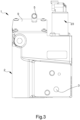
Figure 3 is a second side elevation view of the device inFigure 1 ; -
Figures 4 through 8 are cross-sectional views along the track plane IV-IV of -
Figure 2 that identify five different operating conditions of the device inFigure 1 ; -
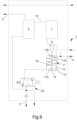
Figure 9 is a schematic representation of the hydraulic circuit of the device inFigure 1 ; -
Figure 10 is a schematic representation of a braking circuit of a vehicle comprising the device inFigure 1 . - With particular reference to these figures,
reference numeral 1 globally denotes a braking device for vehicles, particularly a secondary braking valve. -
Figure 10 shows abraking circuit 100 within which thebraking device 1 is inserted. As can be seen from the figure, thecircuit 100 comprises a main braking device D which can be connected to the brake pedal F of a vehicle and a hydraulic pump P connected to thebraking device 1. The pump P can also be connected, as in the embodiment shown inFigure 10 , to the main braking device D. More specifically, thebraking circuit 100 comprises a feeding channel A adapted to set the pump P in communication with thebraking device 1 and, possibly, with the main braking device D, a first braking channel N1 adapted to set thedevice 1 in communication with the braking circuit I and a second braking channel N2 adapted to set the main braking device D in communication with the braking circuit I. Between the first braking channel N1 and the second braking channel N2 there are valve means V, e.g. of the type of a so-called "shuttle valve", adapted to selectively set the braking circuit I in communication with that of either the first braking channel N1 or the second braking channel N2 having higher pressure. - According to the invention, the
device 1 comprises abody 2 provided with at least oneinlet port 3 of a pressurized working liquid, e.g., oil, with at least oneoutlet port 4 connectable to the braking circuit I of a vehicle, and with at least onedraining port 5 connectable to a draining tank. - Specifically, the
inlet port 3 is connectable to the pump P and theoutlet port 4 is connectable to the second braking channel N2 of thecircuit 100. - The
device 1 then comprises afirst tank 6 provided with aninlet spout 26 of the working liquid and open at the top to define a firstupper port 6a, and asecond tank 7 communicating with thefirst tank 6. - The
first tank 6 and thesecond tank 7 are arranged side by side. - Preferably, the
first tank 6 and thesecond tank 7 are defined within thebody 2. There is then aclosing element 9, e.g. of the type of a lid, of at least the firstupper port 6a. - Advantageously, the
closing element 9 is arranged, in use, (where this definition means the position taken by thedevice 1 during its use), inclined with respect to the horizon. - In the particular, but not exclusive embodiment shown in the figures, the
second tank 7 is also open at the top to define a secondupper port 7a, and theclosing element 9 is arranged raised above theupper ports channel 10 between thefirst tank 6 and thesecond tank 7. In one alternative embodiment, not shown in the figures, thesecond tank 7 is closed at the top by thesame body 2. - Advantageously, the
draining port 5 is defined on theclosing element 9 and is arranged facing the firstupper port 6a. - Preferably, the
closing element 9 is inclined from top to bottom proceeding from thefirst tank 6 towards thesecond tank 7. In other words, the height of theclosing element 9 with respect to a horizontal reference plane turns out to be greater where thefirst tank 6 is located than that measured where thesecond tank 7 is located. This arrangement of theclosing element 9 makes it easier to convey any air bubbles that may be present in the working liquid contained in thesecond tank 7 towards the top of theclosing element 9 and, in particular, towards thedraining port 5. - It follows, therefore, that the working liquid entering inside the
first tank 6 through theinlet spout 26, and possibly containing the air bubbles, once the first tank itself is filled, flows out of the firstupper port 6a, passing through thefiltering element 8, and flows into thesecond tank 7. Any air bubbles in the working liquid that flows out of thefirst tank 6 remain adhered to the filteringelement 8 where its upper face is located. Any air bubbles that are transferred into thesecond tank 7 collect where its upper portion is located, particularly at the free surface of the working liquid contained within it, and the inclination of theclosing element 9 promotes the displacement thereof towards thedraining port 5. - The
device 1 also comprises at least one workingchamber 11 provided with at least one connectingport 12 to thesecond tank 7 and within which at least onebraking piston working chamber 11 into at least onedriving chamber 11a connectable to theinlet port 3 and abraking chamber 11b communicating with theoutlet port 4 and with theconnecting port 12. - Still according to the invention, the
device 1 comprises at least onefiltering element 8 located between theinlet spout 26 and the connectingport 12, which is adapted to allow the passage of the working liquid and to retain the air bubbles contained therein. - In the particular embodiment shown in the figures, the
filtering element 8 is arranged facing the firstupper port 6a. In this embodiment, thedraining port 5 defined on theclosing element 9 is arranged facing the filteringelement 8. - In one alternative embodiment, not shown in the figures, the
filtering element 8 is arranged within at least one of either thefirst tank 6 or thesecond tank 7. Further embodiments cannot however be ruled out wherein the filteringelement 8 is arranged both where thefirst port 6a is located and within at least one of thetanks - More particularly, the
filtering element 8 can be of the slab-shaped type (as in the embodiment shown in the figures), e.g. of the type of a wire mesh, or it can define a closed profile having, e.g., a cylindrical conformation. - The working
chamber 11 has abottom wall 11c and a top 11d opposite each other. The connectingport 12 is defined where the top 11d is located. - Preferably, the
braking chamber 11b is obtained within thebody 2 and is arranged, in use, below thesecond tank 7. - Advantageously, the volume of the
second tank 7 is greater than the maximum volume of thebraking chamber 11b. This ensures that the working liquid contained in thesecond tank 7 can never flow completely into thebraking chamber 11b, thus preventing any air bubbles contained in the second tank itself, which collect at the free surface of the liquid contained within it, from being transferred into thebraking chamber 11b. - At least one
plug element 15 is housed inside theworking chamber 11 and is connected to thebraking piston port 12. In other words, the displacement of theplug element 15 is affected by the movement of thebraking piston - In the preferred embodiment shown in the figures, the
braking piston tumbler element 13 and at least onedriving element 14 inserted passing through the tumbler element itself and connected to theplug element 15 in a kinematic manner. Thedriving element 14 is inserted tightly in a sliding manner within thetumbler element 13. - The
tumbler element 13 is movable by shifting within theworking chamber 11 between a home position, wherein it rests against thebottom wall 11c of the working chamber itself, and at least one braking position, wherein it is raised with respect to thebottom wall 11c. It follows that the greater the distance of thetumbler element 13 from thebottom wall 11c, the greater the volume of the working liquid transferred towards the braking circuit I. - Appropriately, within the
braking chamber 11b are housed firstelastic means 16, which are adapted to push thetumbler element 13 towards the home position. In other words, the firstelastic means 16 are adapted to counteract the displacement of thetumbler element 13 towards the braking position. - In more detail, the
tumbler element 13 defines ahousing seat 13a of the first elastic means 16 which have one end associated with the tumbler element itself and the opposite end operating on the top 11d of thebraking chamber 11b. The first elastic means 16 are, e.g., of the type of a coil spring. As shown in the figures, the upper portion of the firstelastic means 16 is fitted around a spring-guidingelement 17 that rests against the top 11d of the workingchamber 11. More specifically, the spring-guidingelement 17 can be separate from thebody 2 or, alternatively, made in a single piece therewith. - More particularly, the driving
element 14 also faces thebottom wall 11c and moves locked together with thetumbler element 13 during a first stretch of its travel from the home position towards a braking position. - Preferably, the
tumbler element 13 has at least afirst abutment surface 18 adapted to interact with the drivingelement 14 during the displacement from a braking position towards the home position to drag the driving element itself towards thebottom wall 11c. - Appropriately, the driving
element 14 comprises at least one stoppingsurface 19, defined e.g. by a Seeger ring, which is adapted to interact with the spring-guidingelement 17 during its displacement away from thebottom wall 11c. As a result of this interaction, the stroke of the drivingelement 14 away from thebottom wall 11c is limited with respect to that of thetumbler element 13, so that the maximum load that the driving element itself can apply to theplug element 15 to which it is kinematically connected is reduced. - Advantageously, the second elastic means 20 are located between the driving
element 14 and theplug element 15, which are adapted to push the plug element itself towards the connectingport 12 as a result of the displacement of the drivingelement 14 away from thebottom wall 11c. In other words, when the drivingelement 14 moves away from thebottom wall 11c as a result of the increase in pressure in the drivingchamber 11a, the second elastic means 20 in turn push theplug element 15 towards the closing position of the connectingport 12. - Preferably, the equivalent pressure exerted by the first elastic means 16 on the
tumbler element 13 is greater than that exerted by the second elastic means 20 on theplug element 15. - Appropriately, the driving
element 14 has asecond abutment surface 21 adapted to interact with theplug element 15 during its displacement towards thebottom wall 11c so as to drag it away from the connectingport 12. - Then, the
device 1 comprises valve means 22 adapted to set the drivingchamber 11a in communication with theinlet port 3 and/or with thefirst tank 6. - More particularly, the valve means 22 are movable between two extreme working positions where, in the first working position, the
inlet port 3 is closed and the drivingchamber 11a is set in communication with theinlet spout 26 while, in the second working position, theinlet port 3 is set in communication with the drivingchamber 11a and the connection with thefirst tank 6 is closed. - The operation of this invention is as follows.
- In the home condition, shown in
Figure 4 , thebraking piston chamber 11, the drivingchamber 11a is set in communication with thefirst tank 6 through the valve means 22 and thebraking chamber 11b is set in communication with thesecond tank 7 through the connectingport 12, which is opened by theplug element 15. - At the time when the valve means 22 are brought to the second working position, the driving
chamber 11a is set under pressure as a result of the inlet of the working liquid coming from theinlet port 3. As a result of this pressurization, thebraking piston bottom wall 11c. More specifically, both thetumbler element 13 and the drivingelement 14 are raised with respect to thebottom wall 11c, where thetumbler element 13 begins to compress the firstelastic means 16 and the drivingelement 14 exerts a pushing action on theplug element 15, by means of the second elastic means 20, causing the connectingport 12 to close. In this operating condition, shown inFigure 5 , thebraking chamber 11b is isolated from thesecond tank 7 and thefirst tank 6 is isolated from the drivingchamber 11a. - As a result of the further increase in pressure within the driving
chamber 11a, thebraking piston tumbler element 13 further compresses the firstelastic means 16, causing the working liquid contained in thebraking chamber 11b to be sent towards the braking circuit I through theoutlet port 4, while the drivingelement 14 stops its stroke at the moment when the stoppingsurface 19 interacts with thetumbler element 13. This limits the maximum force that the drivingelement 14 is able to exert on theplug element 15. This operating condition is shown inFigure 6 . - The progressive increase in pressure within the driving
chamber 11a then causes the relevant movement of thetumbler element 13, which continues to move away from thebottom wall 11c further compressing the firstelastic means 16, with respect to the drivingelement 14. - Thus, the maximum braking condition of the braking circuit I corresponds to the configuration in which the distance of the
tumbler element 13 from thebottom wall 11c is maximum and, consequently, the volume of thebraking chamber 11b is minimum. This operating condition is shown inFigure 7 . Also in this operating condition, theplug element 15 is kept pressed against the top 11d of the workingchamber 11 so as to close the connectingport 12, so that thebraking chamber 11b is kept isolated from thesecond tank 7. - At the moment when the pressure within the driving
chamber 11a decreases, thetumbler element 13, pushed by the firstelastic means 16, returns towards the home position by drawing within thebraking chamber 11b the pressurized liquid from the braking circuit I through theoutlet port 4. - In the case where the
output port 4 is isolated from the braking circuit, e.g. as a result of the increased braking pressure exerted by the main braking device D that causes the connection to the output port itself to be closed (by means of the shuttle valve V), thetumbler element 13 is prevented from drawing the working liquid from the braking circuit itself, so it is unable to go down towards thebottom wall 11c as a result of the pressure difference at its ends. - In this operating configuration, shown in
Figure 8 , the force exerted by the first elastic means 16 on thetumbler element 13 is greater than that exerted, in the opposite direction, by the second elastic means 20 on theplug element 15. It follows, therefore, that the negative pressure defined within thebraking chamber 1 1b as a result of the force exerted by the first elastic means generates a greater force on theplug element 15 than that exerted thereon by the second elastic means 20, thus causing them to move away from the top 11d and the consequent opening of the connectingport 12. In this way, the working liquid contained in thesecond tank 7 flows within thebraking chamber 11b, thus allowing the complete return of thebraking piston second tank 7 is greater than the maximum volume of thebraking chamber 11b, the working liquid entering the latter is free of air bubbles, which, collecting at its free surface, remain within thesecond tank 7. - As a result of the displacement of the
braking piston bottom wall 11c, the working liquid contained within the drivingchamber 11a is pushed into thefirst tank 6 through the valve means 22, which are arranged in the first working position. - It has in practice been ascertained that the described invention achieves the intended objects, and in particular, the fact is emphasized that the braking device covered by the present invention makes it possible to minimize the risk that any air bubbles contained in the working liquid may enter the inside of the braking chamber, thus limiting the displacement thereof.
- In particular, the simultaneous presence of the two working liquid collection tanks communicating with each other, of the filtering element arranged on top of the first collection tank, of the inclined closing element and of the draining port arranged facing the filtering element, allows for easy and effective de-bubbling of the air possibly contained in the working liquid.
- Again, the sizing of the second tank and of the braking chamber below it, where the latter has a maximum volume less than that of the second tank itself, makes it possible to prevent any air bubbles left within the second tank from flowing into the braking chamber itself as a result of the opening of the connecting port located between them.
Claims (17)
- Braking device characterized by the fact that it comprises:- a body (2) provided with at least one inlet port (3) of a pressurized working liquid, with at least one outlet port (4) connectable to the braking circuit (I) of a vehicle, and with at least one draining port (5) connectable to a draining tank;- a first tank (6) provided with an inlet spout (26) of the working liquid and open at the top to define a first upper port (6a) and a second tank (7) communicating with said first tank (6),- a closing element (9) of at least said first upper port (6a);- at least one working chamber (11) provided with at least one connecting port (12) to said second tank (7) and within which at least one braking piston (13,14) is housed sealing in a sliding manner which divides said working chamber (11) into at least one driving chamber (11a) connectable to said inlet port (3) and a braking chamber (11b) communicating with said outlet port (4) and with said connecting port (12), at least one plug element (15) being provided and connected to said braking piston (13,14) in a kinematic manner and adapted to open/close said connecting port (12);- at least one filtering element (8) located between said inlet spout (26) and said connecting port (12) and adapted to allow the passage of the working liquid and to retain the air bubbles contained therein.
- Device (1) according to claim 1, characterized by the fact that said draining port (5) is defined on said closing element (9) and is arranged facing said first upper port (6a).
- Device (1) according to claim 1 or 2, characterized by the fact that said filtering element (8) is arranged where said first upper port (6a) is located.
- Device (1) according to one or more of the preceding claims, characterized by the fact that said filtering element (8) is arranged within said first tank (6) and defines a closed profile.
- Device (1) according to one or more of the preceding claims, characterized by the fact that said filtering element (8) is arranged within said second tank (7).
- Device (1) according to one or more of the preceding claims, characterized by the fact that said closing element (9) is arranged, in use, inclined with respect to the horizon.
- Device (1) according to one or more of the preceding claims, characterized by the fact that said closing element (9) is oriented from top to bottom proceeding from said first tank (6) towards said second tank (7).
- Device (1) according to one or more of the preceding claims, characterized by the fact that the maximum volume of said braking chamber (11b) is less than the volume of said second tank (7).
- Device (1) according to one or more of the preceding claims, characterized by the fact that said braking piston (13,14) comprises at least one tumbler element (13) and one driving element (14) inserted passing through said tumbler element (13) and connected to said plug element (15) in a kinematic manner.
- Device (1) according to claim 9, characterized by the fact that said tumbler element (13) is movable by shifting within said working chamber (11) between a home position, wherein it rests against the bottom wall (11c) of the working chamber itself, and at least a braking position, wherein it is raised with respect to said bottom wall (11c), first elastic means (16) being provided adapted to push said tumbler element (13) towards the home position.
- Device (1) according to claim 10, characterized by the fact that said driving element (14) also faces said bottom wall (11c) and moves locked together with said tumbler element (13) during a first stretch of its travel from the home position towards a braking position.
- Device (1) according to one or more of claims 9 to 11, characterized by the fact that said tumbler element (13) comprises at least a first abutment surface (18) adapted to interact with said driving element (14) during the displacement from a braking position towards the home position to drag the driving element itself towards said bottom wall (11c).
- Device (1) according to one or more of claims 9 to 12, characterized by the fact that it comprises at least one spring-guiding element (17) arranged in said braking chamber (11b) and around which said first elastic means (16) are fitted and by the fact that said driving element (14) comprises at least one stopping surface (19) adapted to interact with said spring-guiding element (17) during its displacement away from said bottom wall.
- Device (1) according to one or more of claims 9 to 13, characterized by the fact that it comprises second elastic means (20) located between said driving element (14) and said plug element (15) and adapted to push the latter towards said connecting port (12) as a result of the displacement of said driving element (14) away from said bottom wall (11c).
- Device (1) according to claim 14, characterized by the fact that the equivalent pressure exerted by said first elastic means (16) on said tumbler element (13) is greater than that exerted by said second elastic means (20) on said plug element (15).
- Device (1) according to one or more of claims 9 to 15, characterized by the fact that said driving element (14) comprises a second abutment surface (21) adapted to interact with said plug element (15) during its displacement towards said bottom wall so as to drag it away from said connecting port (12).
- Device (1) according to one or more of the preceding claims, characterized by the fact that it comprises valve means (22) adapted to set said driving chamber (11a) in communication with said inlet port (3) and/or with said first tank (6).
Applications Claiming Priority (1)
| Application Number | Priority Date | Filing Date | Title |
|---|---|---|---|
| IT102023000007437A IT202300007437A1 (en) | 2023-04-17 | 2023-04-17 | VEHICLE BRAKING DEVICE |
Publications (2)
| Publication Number | Publication Date |
|---|---|
| EP4484232A1 true EP4484232A1 (en) | 2025-01-01 |
| EP4484232B1 EP4484232B1 (en) | 2026-04-29 |
Family
ID=87514186
Family Applications (1)
| Application Number | Title | Priority Date | Filing Date |
|---|---|---|---|
| EP24167015.7A Active EP4484232B1 (en) | 2023-04-17 | 2024-03-27 | Braking device for vehicles |
Country Status (2)
| Country | Link |
|---|---|
| EP (1) | EP4484232B1 (en) |
| IT (1) | IT202300007437A1 (en) |
Citations (3)
| Publication number | Priority date | Publication date | Assignee | Title |
|---|---|---|---|---|
| US4721343A (en) * | 1985-06-20 | 1988-01-26 | Honda, Giken Kogyo Kabushiki Kaisha | Hydraulic braking pressure control apparatus for an anti-lock braking system of motor vehicles |
| KR20060063088A (en) * | 2004-12-07 | 2006-06-12 | 주식회사 만도 | Master cylinder |
| US10814850B2 (en) * | 2016-05-04 | 2020-10-27 | Ginda New-Tech Co., Ltd. | Hydraulic brake device with a time difference and assembly thereof |
-
2023
- 2023-04-17 IT IT102023000007437A patent/IT202300007437A1/en unknown
-
2024
- 2024-03-27 EP EP24167015.7A patent/EP4484232B1/en active Active
Patent Citations (3)
| Publication number | Priority date | Publication date | Assignee | Title |
|---|---|---|---|---|
| US4721343A (en) * | 1985-06-20 | 1988-01-26 | Honda, Giken Kogyo Kabushiki Kaisha | Hydraulic braking pressure control apparatus for an anti-lock braking system of motor vehicles |
| KR20060063088A (en) * | 2004-12-07 | 2006-06-12 | 주식회사 만도 | Master cylinder |
| US10814850B2 (en) * | 2016-05-04 | 2020-10-27 | Ginda New-Tech Co., Ltd. | Hydraulic brake device with a time difference and assembly thereof |
Also Published As
| Publication number | Publication date |
|---|---|
| IT202300007437A1 (en) | 2024-10-17 |
| EP4484232B1 (en) | 2026-04-29 |
Similar Documents
| Publication | Publication Date | Title |
|---|---|---|
| EP2398683B1 (en) | Valve assembly | |
| CN103253251A (en) | Brake actuator | |
| DE4015664A1 (en) | HYDRAULIC ANTI-BLOCK BRAKE SYSTEM | |
| KR101948335B1 (en) | Hydraulic unit | |
| EP0605461A1 (en) | ELECTROMAGNETICALLY CONTROLLED VALVE, PARTICULARLY FOR HYDRAULIC BRAKING SYSTEMS OF MOTOR VEHICLES. | |
| US3593978A (en) | Hydro-pneumatic spring system, especially for motor vehicles | |
| EP4484232A1 (en) | Braking device for vehicles | |
| US4412701A (en) | Hydraulic brake system | |
| CN101954903A (en) | The control cock and the corresponding motor vehicle braking system that are used for motor vehicle braking system | |
| US4811809A (en) | Traction slip control device | |
| US3439958A (en) | Control valve in pressure medium brake devices of vehicles applicable in one conduit-,as well as two-conduit-operations | |
| JPS6127749A (en) | Hydraulic controller for vehicular brake | |
| US2683352A (en) | Tilting valve master cylinder for hydraulic brake systems | |
| US4135768A (en) | Accelerator device for control valve of an air brake system for a railway vehicle | |
| DE3737579C2 (en) | Trailer brake valve | |
| CN115556735B (en) | Self-adjusting relay valve | |
| JP7603692B2 (en) | Check valve for hydraulic non-human-powered vehicle brake equipment, and hydraulic non-human-powered vehicle brake equipment | |
| US4445330A (en) | Master cylinder assembly and booster | |
| US2405759A (en) | Combined air hydraulic pressure actuating system | |
| US5044400A (en) | Control valve assembly for pressurized oil | |
| DE4319161A1 (en) | Slip-controlled hydraulic brake system | |
| EP0412274B1 (en) | Hydraulic brake installation for a trailer vehicle | |
| DE19806420A1 (en) | Hydraulic operating device for vehicle clutch units | |
| DE3917145A1 (en) | Hydraulic braking unit for trailer vehicle - has braking valve which supplies pressure medium flow from source across flow regulating valve to brake unit | |
| US3064581A (en) | Reciprocating hydraulic pumps |
Legal Events
| Date | Code | Title | Description |
|---|---|---|---|
| PUAI | Public reference made under article 153(3) epc to a published international application that has entered the european phase |
Free format text: ORIGINAL CODE: 0009012 |
|
| STAA | Information on the status of an ep patent application or granted ep patent |
Free format text: STATUS: THE APPLICATION HAS BEEN PUBLISHED |
|
| AK | Designated contracting states |
Kind code of ref document: A1 Designated state(s): AL AT BE BG CH CY CZ DE DK EE ES FI FR GB GR HR HU IE IS IT LI LT LU LV MC ME MK MT NL NO PL PT RO RS SE SI SK SM TR |
|
| STAA | Information on the status of an ep patent application or granted ep patent |
Free format text: STATUS: REQUEST FOR EXAMINATION WAS MADE |
|
| 17P | Request for examination filed |
Effective date: 20250701 |
|
| GRAP | Despatch of communication of intention to grant a patent |
Free format text: ORIGINAL CODE: EPIDOSNIGR1 |
|
| STAA | Information on the status of an ep patent application or granted ep patent |
Free format text: STATUS: GRANT OF PATENT IS INTENDED |
|
| INTG | Intention to grant announced |
Effective date: 20251211 |
|
| GRAS | Grant fee paid |
Free format text: ORIGINAL CODE: EPIDOSNIGR3 |
|
| GRAA | (expected) grant |
Free format text: ORIGINAL CODE: 0009210 |
|
| STAA | Information on the status of an ep patent application or granted ep patent |
Free format text: STATUS: THE PATENT HAS BEEN GRANTED |
|
| AK | Designated contracting states |
Kind code of ref document: B1 Designated state(s): AL AT BE BG CH CY CZ DE DK EE ES FI FR GB GR HR HU IE IS IT LI LT LU LV MC ME MK MT NL NO PL PT RO RS SE SI SK SM TR |
|
| REG | Reference to a national code |
Ref country code: CH Ref legal event code: F10 Free format text: ST27 STATUS EVENT CODE: U-0-0-F10-F00 (AS PROVIDED BY THE NATIONAL OFFICE) Effective date: 20260429 |