EP4484214A1 - Wireless communication method, and battery system for providing method - Google Patents
Wireless communication method, and battery system for providing method Download PDFInfo
- Publication number
- EP4484214A1 EP4484214A1 EP23835725.5A EP23835725A EP4484214A1 EP 4484214 A1 EP4484214 A1 EP 4484214A1 EP 23835725 A EP23835725 A EP 23835725A EP 4484214 A1 EP4484214 A1 EP 4484214A1
- Authority
- EP
- European Patent Office
- Prior art keywords
- battery
- ground
- bms
- communication unit
- signal
- Prior art date
- Legal status (The legal status is an assumption and is not a legal conclusion. Google has not performed a legal analysis and makes no representation as to the accuracy of the status listed.)
- Granted
Links
Images



Classifications
-
- H—ELECTRICITY
- H01—ELECTRIC ELEMENTS
- H01M—PROCESSES OR MEANS, e.g. BATTERIES, FOR THE DIRECT CONVERSION OF CHEMICAL ENERGY INTO ELECTRICAL ENERGY
- H01M10/00—Secondary cells; Manufacture thereof
- H01M10/42—Methods or arrangements for servicing or maintenance of secondary cells or secondary half-cells
- H01M10/425—Structural combination with electronic components, e.g. electronic circuits integrated to the outside of the casing
- H01M10/4264—Structural combination with electronic components, e.g. electronic circuits integrated to the outside of the casing with capacitors
-
- B—PERFORMING OPERATIONS; TRANSPORTING
- B60—VEHICLES IN GENERAL
- B60L—PROPULSION OF ELECTRICALLY-PROPELLED VEHICLES; SUPPLYING ELECTRIC POWER FOR AUXILIARY EQUIPMENT OF ELECTRICALLY-PROPELLED VEHICLES; ELECTRODYNAMIC BRAKE SYSTEMS FOR VEHICLES IN GENERAL; MAGNETIC SUSPENSION OR LEVITATION FOR VEHICLES; MONITORING OPERATING VARIABLES OF ELECTRICALLY-PROPELLED VEHICLES; ELECTRIC SAFETY DEVICES FOR ELECTRICALLY-PROPELLED VEHICLES
- B60L58/00—Methods or circuit arrangements for monitoring or controlling batteries or fuel cells, specially adapted for electric vehicles
- B60L58/10—Methods or circuit arrangements for monitoring or controlling batteries or fuel cells, specially adapted for electric vehicles for monitoring or controlling batteries
- B60L58/12—Methods or circuit arrangements for monitoring or controlling batteries or fuel cells, specially adapted for electric vehicles for monitoring or controlling batteries responding to state of charge [SoC]
-
- B—PERFORMING OPERATIONS; TRANSPORTING
- B60—VEHICLES IN GENERAL
- B60L—PROPULSION OF ELECTRICALLY-PROPELLED VEHICLES; SUPPLYING ELECTRIC POWER FOR AUXILIARY EQUIPMENT OF ELECTRICALLY-PROPELLED VEHICLES; ELECTRODYNAMIC BRAKE SYSTEMS FOR VEHICLES IN GENERAL; MAGNETIC SUSPENSION OR LEVITATION FOR VEHICLES; MONITORING OPERATING VARIABLES OF ELECTRICALLY-PROPELLED VEHICLES; ELECTRIC SAFETY DEVICES FOR ELECTRICALLY-PROPELLED VEHICLES
- B60L58/00—Methods or circuit arrangements for monitoring or controlling batteries or fuel cells, specially adapted for electric vehicles
- B60L58/10—Methods or circuit arrangements for monitoring or controlling batteries or fuel cells, specially adapted for electric vehicles for monitoring or controlling batteries
- B60L58/18—Methods or circuit arrangements for monitoring or controlling batteries or fuel cells, specially adapted for electric vehicles for monitoring or controlling batteries of two or more battery modules
-
- H—ELECTRICITY
- H01—ELECTRIC ELEMENTS
- H01M—PROCESSES OR MEANS, e.g. BATTERIES, FOR THE DIRECT CONVERSION OF CHEMICAL ENERGY INTO ELECTRICAL ENERGY
- H01M10/00—Secondary cells; Manufacture thereof
- H01M10/42—Methods or arrangements for servicing or maintenance of secondary cells or secondary half-cells
- H01M10/48—Accumulators combined with arrangements for measuring, testing or indicating the condition of cells, e.g. the level or density of the electrolyte
- H01M10/482—Accumulators combined with arrangements for measuring, testing or indicating the condition of cells, e.g. the level or density of the electrolyte for several batteries or cells simultaneously or sequentially
-
- H—ELECTRICITY
- H04—ELECTRIC COMMUNICATION TECHNIQUE
- H04Q—SELECTING
- H04Q9/00—Arrangements in telecontrol or telemetry systems for selectively calling a substation from a main station, in which substation desired apparatus is selected for applying a control signal thereto or for obtaining measured values therefrom
-
- B—PERFORMING OPERATIONS; TRANSPORTING
- B60—VEHICLES IN GENERAL
- B60R—VEHICLES, VEHICLE FITTINGS, OR VEHICLE PARTS, NOT OTHERWISE PROVIDED FOR
- B60R16/00—Electric or fluid circuits specially adapted for vehicles and not otherwise provided for; Arrangement of elements of electric or fluid circuits specially adapted for vehicles and not otherwise provided for
- B60R16/02—Electric or fluid circuits specially adapted for vehicles and not otherwise provided for; Arrangement of elements of electric or fluid circuits specially adapted for vehicles and not otherwise provided for electric constitutive elements
- B60R16/023—Electric or fluid circuits specially adapted for vehicles and not otherwise provided for; Arrangement of elements of electric or fluid circuits specially adapted for vehicles and not otherwise provided for electric constitutive elements for transmission of signals between vehicle parts or subsystems
-
- B—PERFORMING OPERATIONS; TRANSPORTING
- B60—VEHICLES IN GENERAL
- B60Y—INDEXING SCHEME RELATING TO ASPECTS CROSS-CUTTING VEHICLE TECHNOLOGY
- B60Y2200/00—Type of vehicle
- B60Y2200/90—Vehicles comprising electric prime movers
- B60Y2200/91—Electric vehicles
-
- B—PERFORMING OPERATIONS; TRANSPORTING
- B60—VEHICLES IN GENERAL
- B60Y—INDEXING SCHEME RELATING TO ASPECTS CROSS-CUTTING VEHICLE TECHNOLOGY
- B60Y2400/00—Special features of vehicle units
- B60Y2400/11—Electric energy storages
- B60Y2400/112—Batteries
-
- H—ELECTRICITY
- H01—ELECTRIC ELEMENTS
- H01M—PROCESSES OR MEANS, e.g. BATTERIES, FOR THE DIRECT CONVERSION OF CHEMICAL ENERGY INTO ELECTRICAL ENERGY
- H01M10/00—Secondary cells; Manufacture thereof
- H01M10/42—Methods or arrangements for servicing or maintenance of secondary cells or secondary half-cells
- H01M10/425—Structural combination with electronic components, e.g. electronic circuits integrated to the outside of the casing
- H01M2010/4271—Battery management systems including electronic circuits, e.g. control of current or voltage to keep battery in healthy state, cell balancing
-
- H—ELECTRICITY
- H01—ELECTRIC ELEMENTS
- H01M—PROCESSES OR MEANS, e.g. BATTERIES, FOR THE DIRECT CONVERSION OF CHEMICAL ENERGY INTO ELECTRICAL ENERGY
- H01M10/00—Secondary cells; Manufacture thereof
- H01M10/42—Methods or arrangements for servicing or maintenance of secondary cells or secondary half-cells
- H01M10/425—Structural combination with electronic components, e.g. electronic circuits integrated to the outside of the casing
- H01M2010/4278—Systems for data transfer from batteries, e.g. transfer of battery parameters to a controller, data transferred between battery controller and main controller
-
- H—ELECTRICITY
- H04—ELECTRIC COMMUNICATION TECHNIQUE
- H04W—WIRELESS COMMUNICATION NETWORKS
- H04W84/00—Network topologies
- H04W84/18—Self-organising networks, e.g. ad-hoc networks or sensor networks
- H04W84/20—Leader-follower arrangements
-
- Y—GENERAL TAGGING OF NEW TECHNOLOGICAL DEVELOPMENTS; GENERAL TAGGING OF CROSS-SECTIONAL TECHNOLOGIES SPANNING OVER SEVERAL SECTIONS OF THE IPC; TECHNICAL SUBJECTS COVERED BY FORMER USPC CROSS-REFERENCE ART COLLECTIONS [XRACs] AND DIGESTS
- Y02—TECHNOLOGIES OR APPLICATIONS FOR MITIGATION OR ADAPTATION AGAINST CLIMATE CHANGE
- Y02E—REDUCTION OF GREENHOUSE GAS [GHG] EMISSIONS, RELATED TO ENERGY GENERATION, TRANSMISSION OR DISTRIBUTION
- Y02E60/00—Enabling technologies; Technologies with a potential or indirect contribution to GHG emissions mitigation
- Y02E60/10—Energy storage using batteries
-
- Y—GENERAL TAGGING OF NEW TECHNOLOGICAL DEVELOPMENTS; GENERAL TAGGING OF CROSS-SECTIONAL TECHNOLOGIES SPANNING OVER SEVERAL SECTIONS OF THE IPC; TECHNICAL SUBJECTS COVERED BY FORMER USPC CROSS-REFERENCE ART COLLECTIONS [XRACs] AND DIGESTS
- Y02—TECHNOLOGIES OR APPLICATIONS FOR MITIGATION OR ADAPTATION AGAINST CLIMATE CHANGE
- Y02T—CLIMATE CHANGE MITIGATION TECHNOLOGIES RELATED TO TRANSPORTATION
- Y02T10/00—Road transport of goods or passengers
- Y02T10/60—Other road transportation technologies with climate change mitigation effect
- Y02T10/70—Energy storage systems for electromobility, e.g. batteries
-
- Y—GENERAL TAGGING OF NEW TECHNOLOGICAL DEVELOPMENTS; GENERAL TAGGING OF CROSS-SECTIONAL TECHNOLOGIES SPANNING OVER SEVERAL SECTIONS OF THE IPC; TECHNICAL SUBJECTS COVERED BY FORMER USPC CROSS-REFERENCE ART COLLECTIONS [XRACs] AND DIGESTS
- Y02—TECHNOLOGIES OR APPLICATIONS FOR MITIGATION OR ADAPTATION AGAINST CLIMATE CHANGE
- Y02T—CLIMATE CHANGE MITIGATION TECHNOLOGIES RELATED TO TRANSPORTATION
- Y02T10/00—Road transport of goods or passengers
- Y02T10/60—Other road transportation technologies with climate change mitigation effect
- Y02T10/72—Electric energy management in electromobility
Definitions
- the present disclosure relates to a wireless communication method between a plurality of battery management systems (BMSs) and a battery system providing the same.
- BMSs battery management systems
- a battery system applied to an electric vehicle or the like may include a plurality of battery packs, each including a battery module and a slave battery management system (BMS) managing the battery module.
- the battery system may further include a master battery management system (BMS) communicating with a vehicle system and managing the plurality of battery packs.
- BMS slave battery management system
- the present disclosure attempts to provide a wireless communication method capable of wireless communication between a plurality of battery management systems (BMSs) without adding a separate component for wireless communication, and a battery system providing the same.
- BMSs battery management systems
- the present disclosure attempts to provide a wireless communication method capable of wireless communication between a plurality of battery management systems (BMS) in various industrial scientific and medical (ISM) bands, and a battery system providing the same.
- BMS battery management systems
- ISM industrial scientific and medical
- An exemplary embodiment of the present disclosure provides a battery system including at least one battery pack including a battery module and a slave battery management system (BMS) managing the battery module includes: a communication unit of the slave BMS; a capacitor connected between the communication unit and a first ground; an inductor connected between a contact between the first ground and the capacitor and a second ground; and a controller configured to transmit an AC signal having a predetermined frequency to the communication unit in an antenna mode, wherein in the antenna mode, the slave BMS is configured to communicate with the outside.
- BMS slave battery management system
- the inductor may be located between the battery module and the slave BMS.
- a length between the inductor and the first ground may correspond to 1/4 of a wavelength of the AC signal.
- the first ground may be a signal ground of the slave BMS, and the second ground may be a chassis ground of the battery module.
- control unit may transmit a DC signal to the communication unit.
- the battery system may further include a master BMS communicating with the communication unit in a wireless manner to manage the at least one slave BMS.
- the controller may be further configured to transmit the collected battery data to the master BMS through the communication unit.
- Another exemplary embodiment of the present disclosure provides a wireless communication method in a battery system including a communication unit of a slave battery management system (BMS) managing a battery module, a capacitor connected between the communication unit and a first ground, and an inductor connected between a contact between the first ground and the capacitor and a second ground, the method includes transmitting an AC signal having a predetermined frequency to the communication unit to configure the slave BMS to communicate with the outside.
- BMS slave battery management system
- the inductor may be located between the battery module and the slave BMS.
- a length between the inductor and the first ground may correspond to 1/4 of a wavelength of the AC signal.
- the first ground may be a signal ground of the slave BMS, and the second ground may be a chassis ground of the battery module.
- the battery system may further include a monitoring unit electrically connected to each of a plurality of battery cells included in the battery module to collect battery data including at least one of a current, a voltage, and a temperature for each of the plurality of battery cells.
- the wireless communication method may further include collecting the battery data by the monitoring unit, before the communication with the outside, wherein the collection of the battery data includes transmitting a DC signal to the communication unit.
- the communication with the outside may include transmitting the collected battery data to a master BMS managing the slave BMS through the communication unit.
- a component e.g., an antenna
- PCB printed circuit board
- the cost can be reduced because there is no need to purchase a component (e.g., an antenna) for wireless communication.
- a component e.g., an antenna
- one component when one component is referred to as being “connected to” or “coupled to” another component, one component may be connected or coupled directly to another component, or one component may be connected or coupled to another component with an intervening component therebetween.
- one component when one component is referred to as being “directly connected to” or “directly coupled to” another component, one component may be connected to another component with no intervening component therebetween.
- FIG. 1 is a block diagram illustrating a battery system according to an exemplary embodiment.
- FIG. 2 is a block diagram illustrating a battery pack of FIG. 1 in detail.
- a battery system 1 includes a battery 10 and a master battery management system (hereinafter referred to as a master BMS) 20.
- a master BMS master battery management system
- the battery 10 includes at least one battery pack.
- a plurality of battery packs 10_1 to 10_n are illustrated, but the number of battery packs is not limited thereto, and the battery 10 may include one battery pack 10_1.
- reference sign "10_j” will be used to denote a specific battery pack among the plurality of battery packs 10_1 to 10_n, and reference signs “100j” and “200j” will be used to denote a battery module and a slave BMS included in the battery pack 10_j, respectively.
- reference signs "Cj”, “Lj”, “Nj”, and “200_Aj” will be used to denote a capacitor, an inductor, a contact, and an antenna included in the battery pack 10_j, respectively, to be described below.
- the battery pack 10_j includes a battery module 100j and a slave BMS 200j.
- the battery module 100j may include a plurality of battery cells connected to each other in series and/or in parallel.
- the battery cell may be a rechargeable secondary battery.
- FIGS. 1 and 2 it is illustrated that the battery module 100j includes three battery cells Cell1, Cell2, and Cell3 connected to each other in series, but the number of battery cells is not limited thereto.
- the battery module 100j may include any number of battery cells.
- the slave BMS 200j may collect battery data for the battery module 100j and transmit the collected battery data to a master BMS 20 through wireless communication.
- the battery data may include at least one of a cell voltage, a cell current, and a cell temperature for each of the plurality of battery cells Cell1, Cell2, and Cell3.
- the battery data may include at least one of a module voltage, which is a voltage at both ends of the battery module 100j, and a module current, which is a current flowing through the battery module 100j.
- the slave BMS 200j may include a monitoring unit 210, a communication unit 220, a control unit 230, a capacitor Cj, and an inductor Lj.
- the monitoring unit 210 is electrically connected to the battery module 100j to collect battery data.
- the monitoring unit 210 is an integrated circuit (IC) capable of collecting battery data, and may include an application specific IC (ASIC), a battery monitoring IC (BMIC), or the like.
- ASIC application specific IC
- BMIC battery monitoring IC
- the monitoring unit 210 is electrically connected to positive and negative electrodes of each of the plurality of battery cells Cell1, Cell2, and Cell3, and the plurality of battery cells Cell1, Cell2, and Cell3 measure a cell voltage of each of the plurality of battery cells Cell1, Cell2, and Cell3.
- the monitoring unit 210 may receive information about a cell current and a cell temperature measured by a current sensor (not shown) and a temperature sensor (not shown), respectively.
- the monitoring unit 210 may measure a cell voltage of each of the plurality of battery cells Cell1, Cell2, and Cell3 at every predetermined cycle during a rest period in which charging and discharging does not occur, and calculate a cell current based on the measured cell voltage.
- the monitoring unit 210 may collect battery data at every predetermined cycle or in real time, and transmit the collected battery data to the control unit 230.
- the communication unit 220 may be an analog signal processing device that processes data to be transmitted.
- the communication unit 220 may include a radio frequency IC (RFIC), but is not limited thereto.
- RFIC radio frequency IC
- the control unit 230 may convert a digital signal into an analog signal (alternating current signal, AC signal) and transmit the converted signal to the communication unit 220. Then, the communication unit 220 processes the analog signal by amplifying and filtering the analog signal, and transmits the processed analog signal to the antenna.
- the antenna may convert the processed analog signal into an electromagnetic wave and transmit the electromagnetic wave into the air.
- the antenna may be an antenna generated in an antenna mode, and the antenna will be described in detail with reference to FIGS. 4 and 5 below.
- the control unit 230 may control an overall operation of the slave BMS 200j.
- the monitoring unit 210 may be controlled to collect battery data
- the communication unit 220 may be controlled to transmit the collected battery data to the master BMS 20.
- a capacitor Cj may be connected between the communication unit 220 and a first ground GND1.
- the first ground GND1 may be a signal ground located in the slave BMS 200j, but is not limited thereto.
- the first ground GND1 may be implemented by an earth ground or a chassis ground.
- An inductor Lj may be connected between a second ground GND2 and a contact Nj between the first ground GND1 and the capacitor Cj.
- the second ground GND2 may be a chassis ground located in the battery module 100j, but is not limited thereto.
- the second ground GND2 may be implemented by an earth ground or a signal ground.
- the inductor Lj may be located in an external space between the battery module 100j and the slave BMS 200j. Specifically, one end of the inductor Lj connected to the contact Nj may be located outside a housing of the slave BMS 200j.
- the master BMS 20 may communicate with a superordinate control unit 2 to receive commands and information, and manage and control the slave BMS 200j included in at least one battery pack 10_j according to the received commands.
- the superordinate control unit 2 may be a control unit of a superordinate system (e.g., a vehicle, an ESS system, etc.) in which the battery system 1 is mounted.
- the master BMS 20 may communicate with each of the plurality of slave BMSs 2001 to 200N in a wireless manner to transmit various control signals or receive battery data.
- An external device illustrated in FIG. 1 may be a charger in a charging mode for charging the battery 10, or a load (e.g., a motor) in a discharging mode for discharging the battery 10.
- the slave BMS 200j according to an exemplary embodiment is capable of wireless communication with the master BMS 20 without including a separate antenna device. This will be described in detail with reference to FIGS. 4 and 5 below.
- FIG. 3 is a block diagram illustrating the battery pack of FIG. 1 when operating in a monitoring mode in detail.
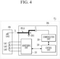
- FIG. 4 is a block diagram illustrating the battery pack of FIG. 1 when operating in an antenna mode in detail.
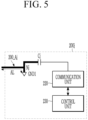
- FIG. 5 is a block diagram illustrating an antenna of FIG. 4 in detail.
- the battery pack 10_j may operate in a monitoring mode for collecting battery data or in an antenna mode for communicating with the outside.
- a structure of the battery pack 10_j in the monitoring mode will be described in detail with reference to FIG. 3
- a structure of the battery pack 10_j in the antenna mode will be described in detail with reference to FIGS. 4 and 5 .
- control unit 230 may control the communication unit 220 to transmit a direct current (DC) signal to the capacitor Cj.
- DC direct current
- a circuit as illustrated in FIG. 3 may be formed according to the electrical characteristics of the capacitor Cj that is opened in response to the DC signal. That is, one end of the inductor Lj may be connected to the first ground GND1, and the other end of the inductor Lj may be connected to the second ground GND2. At this time, external noise may be removed by the inductor Lj.
- control unit 230 may control the communication unit 220 to transfer an AC signal having a predetermined frequency to the capacitor Cj.
- the inverted-F antenna is an antenna made to improve impedance matching of an inverted-L antenna.
- the inverted-L antenna may be an antenna made by horizontally bending about 80% of a length of a monopole antenna with respect to the upper side thereof to reduce its height.
- the antenna 200_Aj may convert an AC signal input through the communication unit 220 into an electromagnetic wave, and transmit the converted electromagnetic wave into the air.
- the antenna Aj may receive an electromagnetic wave, convert the received electromagnetic wave into an AC signal, and transfer the converted AC signal to the communication unit 220.
- the antenna 200_Aj may resonate at a frequency having a wavelength ⁇ of four times the antenna length AL.
- the antenna length AL may correspond to a length between the inductor Lj and the first ground GND1.
- the antenna length AL may be 30.61 mm.
- the antenna length AL may be 81.97mm.
- the antenna length AL may be determined according to the position (mounting distance) of the inductor Lj. That is, by a simple manipulation of changing the position where the inductor Lj is mounted, the slave BMS 200j can perform wireless communication with the master BMS 20 in various industrial scientific and medical (ISM) frequency bands.
- ISM industrial scientific and medical
- FIG. 6 is a flowchart illustrating a wireless communication method according to an exemplary embodiment.
- the monitoring unit 210 collects battery data (S100).
- the monitoring unit 210 may collect battery data at every predetermined cycle or in real time, and transmit the collected battery data to the control unit 230.
- the battery data may include at least one of a cell voltage, a cell current, and a cell temperature for each of the plurality of battery cells Cell1, Cell2, and Cell3.
- the battery data may include at least one of a module voltage, which is a voltage at both ends of the battery module 100j, and a module current, which is a current flowing through the battery module 100j.
- the control unit 230 may control the communication unit 220 to transmit a DC signal to the capacitor Cj.
- a circuit as illustrated in FIG. 3 may be formed according to the electrical characteristics of the capacitor Cj that is opened in response to the DC signal. That is, both ends of the inductor Lj may be connected to the first ground GND1 and the second ground GND2, respectively, such that the inductor Lj is positioned between the first ground GND1 and the second ground GND2.
- external noise may be removed by the inductor Lj.
- the monitoring unit 210 may collect battery data less influenced by external noise.
- control unit 230 transmits the battery data collected through the communication unit 220 to the master BMS 20 (S200).
- control unit 230 may transmit battery data to the BMS 20 through the communication unit 220.
- control unit 230 may communicate with the outside in a wireless manner through the communication unit 220 to transmit various types of information or receive a control signal
- the outside may be the master BMS 20, but is not limited thereto, and may include various devices located outside the slave BMS 200j.
- the control unit 230 may control the communication unit 220 to transmit an AC signal having a predetermined frequency to the capacitor Cj.
- a circuit as illustrated in FIG. 4 is formed according to the electrical characteristics of the inductor Lj that is opened in response to the AC signal.
- a transmission line (bolded portion) connecting a first terminal connected to the capacitor Cj, a second terminal connected to the first ground GND1, and a third terminal adjacent to the inductor Lj to each other may function as an inverted-F antenna. That is, in an antenna mode step for communicating with the outside, an antenna 200_Aj corresponding to an inverted-F antenna structure may be formed in the slave BMS 200j.
- the inverted-F antenna is an antenna made to improve impedance matching of an inverted-L antenna.
- the inverted-L antenna may be an antenna made by horizontally bending about 80% of a length of a monopole antenna with respect to the upper side thereof to reduce its height.
- the antenna 200_Aj may convert an AC signal input through the communication unit 220 into an electromagnetic wave, and transmit the converted electromagnetic wave into the air.
- the antenna Aj may receive an electromagnetic wave, convert the received electromagnetic wave into an AC signal, and transfer the converted AC signal to the communication unit 220.
- the antenna 200_Aj may resonate at a frequency having a wavelength ⁇ of four times the antenna length AL.
- the antenna length AL may correspond to a length between the inductor Lj and the first ground GND1.
- the antenna length AL may be 30.61 mm.
- the antenna length AL may be 81.97mm.
- the antenna length AL may be determined according to the position (mounting distance) of the inductor Lj. That is, by a simple manipulation of changing the position where the inductor Lj is mounted, the slave BMS 200j can perform wireless communication with the master BMS 20 in various industrial scientific and medical (ISM) frequency bands.
- ISM industrial scientific and medical
Landscapes
- Engineering & Computer Science (AREA)
- Mechanical Engineering (AREA)
- Transportation (AREA)
- Power Engineering (AREA)
- Sustainable Energy (AREA)
- Sustainable Development (AREA)
- Life Sciences & Earth Sciences (AREA)
- Electrochemistry (AREA)
- General Chemical & Material Sciences (AREA)
- Chemical Kinetics & Catalysis (AREA)
- Chemical & Material Sciences (AREA)
- Manufacturing & Machinery (AREA)
- Computer Networks & Wireless Communication (AREA)
- Signal Processing (AREA)
- Microelectronics & Electronic Packaging (AREA)
- Charge And Discharge Circuits For Batteries Or The Like (AREA)
- Transceivers (AREA)
- Battery Mounting, Suspending (AREA)
Abstract
Description
- This application claims priority to and the benefit of
Korean Patent Application No. 1 0-2022-0083730 filed in the Korean Intellectual Property Office on July 07, 2022 - The present disclosure relates to a wireless communication method between a plurality of battery management systems (BMSs) and a battery system providing the same.
- A battery system applied to an electric vehicle or the like may include a plurality of battery packs, each including a battery module and a slave battery management system (BMS) managing the battery module. In addition, the battery system may further include a master battery management system (BMS) communicating with a vehicle system and managing the plurality of battery packs.
- Recently, in order to solve the problems of poor quality of electric wiring and frequent maintenance related to wire cables and connectors, and to increase a mileage by reducing a weight of an electric vehicle, research and development on a method for wireless communication between a master BMS and a plurality of slave BMSs are increasing.
- The present disclosure attempts to provide a wireless communication method capable of wireless communication between a plurality of battery management systems (BMSs) without adding a separate component for wireless communication, and a battery system providing the same.
- Further, the present disclosure attempts to provide a wireless communication method capable of wireless communication between a plurality of battery management systems (BMS) in various industrial scientific and medical (ISM) bands, and a battery system providing the same.
- An exemplary embodiment of the present disclosure provides a battery system including at least one battery pack including a battery module and a slave battery management system (BMS) managing the battery module includes: a communication unit of the slave BMS; a capacitor connected between the communication unit and a first ground; an inductor connected between a contact between the first ground and the capacitor and a second ground; and a controller configured to transmit an AC signal having a predetermined frequency to the communication unit in an antenna mode, wherein in the antenna mode, the slave BMS is configured to communicate with the outside.
- The inductor may be located between the battery module and the slave BMS.
- A length between the inductor and the first ground may correspond to 1/4 of a wavelength of the AC signal.
- The first ground may be a signal ground of the slave BMS, and the second ground may be a chassis ground of the battery module.
- The battery system may further include a monitoring unit electrically connected to each of a plurality of battery cells included in the battery module to collect battery data including at least one of a current, a voltage, and a temperature for each of the plurality of battery cells.
- In a monitoring mode in which the monitoring unit collects the battery data, the control unit may transmit a DC signal to the communication unit.
- The battery system may further include a master BMS communicating with the communication unit in a wireless manner to manage the at least one slave BMS.
- In the antenna mode, the controller may be further configured to transmit the collected battery data to the master BMS through the communication unit.
- Another exemplary embodiment of the present disclosure provides a wireless communication method in a battery system including a communication unit of a slave battery management system (BMS) managing a battery module, a capacitor connected between the communication unit and a first ground, and an inductor connected between a contact between the first ground and the capacitor and a second ground, the method includes transmitting an AC signal having a predetermined frequency to the communication unit to configure the slave BMS to communicate with the outside.
- The inductor may be located between the battery module and the slave BMS.
- A length between the inductor and the first ground may correspond to 1/4 of a wavelength of the AC signal.
- The first ground may be a signal ground of the slave BMS, and the second ground may be a chassis ground of the battery module.
- The battery system may further include a monitoring unit electrically connected to each of a plurality of battery cells included in the battery module to collect battery data including at least one of a current, a voltage, and a temperature for each of the plurality of battery cells.
- The wireless communication method may further include collecting the battery data by the monitoring unit, before the communication with the outside, wherein the collection of the battery data includes transmitting a DC signal to the communication unit.
- The communication with the outside may include transmitting the collected battery data to a master BMS managing the slave BMS through the communication unit.
- According to the present invention, there is no need to add a component (e.g., an antenna) for wireless communication inside a printed circuit board (PCB) for the BMS, and as a result, the size of the PCB for the BMS can be reduced.
- According to the present invention, the cost can be reduced because there is no need to purchase a component (e.g., an antenna) for wireless communication.
- According to the present invention, there is no need to change the PCB for the BMS according to a frequency band, and accordingly, a design of the PCB for the BMS can be commonized.
-
-
FIG. 1 is a block diagram illustrating a battery system according to an exemplary embodiment. -
FIG. 2 is a block diagram illustrating a battery pack ofFIG. 1 in detail. -
FIG. 3 is a block diagram illustrating the battery pack ofFIG. 1 when operating in a monitoring mode in detail. -
FIG. 4 is a block diagram illustrating the battery pack ofFIG. 1 when operating in an antenna mode in detail. -
FIG. 5 is a block diagram illustrating an antenna ofFIG. 4 in detail. -
FIG. 6 is a flowchart illustrating a wireless communication method according to an exemplary embodiment. - Hereinafter, exemplary embodiments will be described in detail with reference to the accompanying drawings. The same or similar components will be denoted by the same or similar reference signs, and overlapping descriptions thereof will be omitted. The suffixes "module" and "unit" for components used in the description below are assigned or mixed in consideration of easiness in writing the specification and do not have distinctive meanings or roles by themselves. In addition, in describing exemplary embodiments in the present specification, detailed descriptions of relevant known technologies will be omitted if they unnecessarily obscure the gist of the exemplary embodiments disclosed in the present specification. Further, the accompanying drawings are provided only to help easily understand exemplary embodiments disclosed in the present specification. It should be understood that the technical idea disclosed in the present specification is not limited by the accompanying drawings, and includes all modifications, equivalents, and substitutions within the spirit and the technical scope of the present disclosure.
- Terms including ordinal numbers such as first and second may be used to describe various components, but these components are not limited by these terms. These terms are used only for the purpose of distinguishing one component from another component.
- It is to be understood that when one component is referred to as being "connected to" or "coupled to" another component, one component may be connected or coupled directly to another component, or one component may be connected or coupled to another component with an intervening component therebetween. On the other hand, it is to be understood that when one component is referred to as being "directly connected to" or "directly coupled to" another component, one component may be connected to another component with no intervening component therebetween.
- It should be understood that terms "include", "have", and the like used in the present application specify the presence of features, numerals, steps, operations, components, parts, or combinations thereof mentioned in the specification, but do not preclude the presence or addition of one or more other features, numerals, steps, operations, components, parts, or combinations thereof.
-
FIG. 1 is a block diagram illustrating a battery system according to an exemplary embodiment.FIG. 2 is a block diagram illustrating a battery pack ofFIG. 1 in detail. - Referring to
FIG. 1 , a battery system 1 includes abattery 10 and a master battery management system (hereinafter referred to as a master BMS) 20. - The
battery 10 includes at least one battery pack. InFIG. 1 , a plurality of battery packs 10_1 to 10_n are illustrated, but the number of battery packs is not limited thereto, and thebattery 10 may include one battery pack 10_1. - Hereinafter, reference sign "10_j" will be used to denote a specific battery pack among the plurality of battery packs 10_1 to 10_n, and reference signs "100j" and "200j" will be used to denote a battery module and a slave BMS included in the battery pack 10_j, respectively. In addition, reference signs "Cj", "Lj", "Nj", and "200_Aj" will be used to denote a capacitor, an inductor, a contact, and an antenna included in the battery pack 10_j, respectively, to be described below.
- The battery pack 10_j includes a
battery module 100j and aslave BMS 200j. - The
battery module 100j may include a plurality of battery cells connected to each other in series and/or in parallel. In some exemplary embodiments, the battery cell may be a rechargeable secondary battery. InFIGS. 1 and2 , it is illustrated that thebattery module 100j includes three battery cells Cell1, Cell2, and Cell3 connected to each other in series, but the number of battery cells is not limited thereto. Thebattery module 100j may include any number of battery cells. - The
slave BMS 200j may collect battery data for thebattery module 100j and transmit the collected battery data to amaster BMS 20 through wireless communication. In this case, the battery data may include at least one of a cell voltage, a cell current, and a cell temperature for each of the plurality of battery cells Cell1, Cell2, and Cell3. In addition, the battery data may include at least one of a module voltage, which is a voltage at both ends of thebattery module 100j, and a module current, which is a current flowing through thebattery module 100j. - Referring to
FIG. 2 , theslave BMS 200j may include amonitoring unit 210, acommunication unit 220, acontrol unit 230, a capacitor Cj, and an inductor Lj. - The
monitoring unit 210 is electrically connected to thebattery module 100j to collect battery data. For example, themonitoring unit 210 is an integrated circuit (IC) capable of collecting battery data, and may include an application specific IC (ASIC), a battery monitoring IC (BMIC), or the like. - Referring to
FIG. 2 , as an example, themonitoring unit 210 is electrically connected to positive and negative electrodes of each of the plurality of battery cells Cell1, Cell2, and Cell3, and the plurality of battery cells Cell1, Cell2, and Cell3 measure a cell voltage of each of the plurality of battery cells Cell1, Cell2, and Cell3. As another example, themonitoring unit 210 may receive information about a cell current and a cell temperature measured by a current sensor (not shown) and a temperature sensor (not shown), respectively. As another example, themonitoring unit 210 may measure a cell voltage of each of the plurality of battery cells Cell1, Cell2, and Cell3 at every predetermined cycle during a rest period in which charging and discharging does not occur, and calculate a cell current based on the measured cell voltage. Themonitoring unit 210 may collect battery data at every predetermined cycle or in real time, and transmit the collected battery data to thecontrol unit 230. - The
communication unit 220 may be an analog signal processing device that processes data to be transmitted. For example, thecommunication unit 220 may include a radio frequency IC (RFIC), but is not limited thereto. - According to an exemplary embodiment, the
control unit 230 may convert a digital signal into an analog signal (alternating current signal, AC signal) and transmit the converted signal to thecommunication unit 220. Then, thecommunication unit 220 processes the analog signal by amplifying and filtering the analog signal, and transmits the processed analog signal to the antenna. The antenna may convert the processed analog signal into an electromagnetic wave and transmit the electromagnetic wave into the air. According to an exemplary embodiment, the antenna may be an antenna generated in an antenna mode, and the antenna will be described in detail with reference toFIGS. 4 and5 below. - The
control unit 230 may control an overall operation of theslave BMS 200j. For example, themonitoring unit 210 may be controlled to collect battery data, and thecommunication unit 220 may be controlled to transmit the collected battery data to themaster BMS 20. - A capacitor Cj may be connected between the
communication unit 220 and a first ground GND1. In this case, the first ground GND1 may be a signal ground located in theslave BMS 200j, but is not limited thereto. For example, the first ground GND1 may be implemented by an earth ground or a chassis ground. - An inductor Lj may be connected between a second ground GND2 and a contact Nj between the first ground GND1 and the capacitor Cj. In this case, the second ground GND2 may be a chassis ground located in the
battery module 100j, but is not limited thereto. For example, the second ground GND2 may be implemented by an earth ground or a signal ground. - According to an exemplary embodiment, referring to
FIG. 2 , the inductor Lj may be located in an external space between thebattery module 100j and theslave BMS 200j. Specifically, one end of the inductor Lj connected to the contact Nj may be located outside a housing of theslave BMS 200j. - The
master BMS 20 may communicate with asuperordinate control unit 2 to receive commands and information, and manage and control theslave BMS 200j included in at least one battery pack 10_j according to the received commands. In this case, thesuperordinate control unit 2 may be a control unit of a superordinate system (e.g., a vehicle, an ESS system, etc.) in which the battery system 1 is mounted. - Referring back to
FIG. 1 , according to an exemplary embodiment, themaster BMS 20 may communicate with each of the plurality ofslave BMSs 2001 to 200N in a wireless manner to transmit various control signals or receive battery data. An external device illustrated inFIG. 1 may be a charger in a charging mode for charging thebattery 10, or a load (e.g., a motor) in a discharging mode for discharging thebattery 10. - The
slave BMS 200j according to an exemplary embodiment is capable of wireless communication with themaster BMS 20 without including a separate antenna device. This will be described in detail with reference toFIGS. 4 and5 below. -
FIG. 3 is a block diagram illustrating the battery pack ofFIG. 1 when operating in a monitoring mode in detail.FIG. 4 is a block diagram illustrating the battery pack ofFIG. 1 when operating in an antenna mode in detail.FIG. 5 is a block diagram illustrating an antenna ofFIG. 4 in detail. - According to an exemplary embodiment, the battery pack 10_j may operate in a monitoring mode for collecting battery data or in an antenna mode for communicating with the outside. Hereinafter, a structure of the battery pack 10_j in the monitoring mode will be described in detail with reference to
FIG. 3 , and a structure of the battery pack 10_j in the antenna mode will be described in detail with reference toFIGS. 4 and5 . - Referring to
FIG. 3 , in the monitoring mode, thecontrol unit 230 may control thecommunication unit 220 to transmit a direct current (DC) signal to the capacitor Cj. - When the DC signal is applied to the capacitor Cj, a circuit as illustrated in
FIG. 3 may be formed according to the electrical characteristics of the capacitor Cj that is opened in response to the DC signal. That is, one end of the inductor Lj may be connected to the first ground GND1, and the other end of the inductor Lj may be connected to the second ground GND2. At this time, external noise may be removed by the inductor Lj. - Referring to
FIG. 4 , in the antenna mode, thecontrol unit 230 may control thecommunication unit 220 to transfer an AC signal having a predetermined frequency to the capacitor Cj. - When the alternating current (AC) signal is applied to the capacitor Cj, a circuit as illustrated in
FIG. 4 may be formed according to the electrical characteristics of the inductor Lj that is opened in response to the AC signal. Specifically, a transmission line (bolded portion) connecting a first terminal connected to the capacitor Cj, a second terminal connected to the first ground GND1, and a third terminal adjacent to the inductor Lj to each other may function as an inverted-F antenna. That is, in the antenna mode for communicating with the outside (e.g., the master BMS), an antenna Aj corresponding to an inverted-F antenna structure may be formed in theslave BMS 200j. - The inverted-F antenna is an antenna made to improve impedance matching of an inverted-L antenna. In this case, the inverted-L antenna may be an antenna made by horizontally bending about 80% of a length of a monopole antenna with respect to the upper side thereof to reduce its height.
- Referring to
FIG. 4 , as an example, the antenna 200_Aj may convert an AC signal input through thecommunication unit 220 into an electromagnetic wave, and transmit the converted electromagnetic wave into the air. As another example, the antenna Aj may receive an electromagnetic wave, convert the received electromagnetic wave into an AC signal, and transfer the converted AC signal to thecommunication unit 220. - Referring to
FIG. 5 , according to an exemplary embodiment, the antenna 200_Aj may resonate at a frequency having a wavelength λ of four times the antenna length AL. Specifically, the inverted-F antenna may be configured to have an antenna length (AL=λ/4) corresponding to 1/4 of a wavelength (λ) of a signal to be transmitted and received. In this case, the antenna length AL may correspond to a length between the inductor Lj and the first ground GND1. - As an example, in order to transmit and receive a signal corresponding to a frequency of 2.45 GHZ, the antenna length AL may be 30.61 mm. As another example, in order to transmit and receive a signal corresponding to a frequency of 915 MHZ, the antenna length AL may be 81.97mm.
- According to an exemplary embodiment, the antenna length AL may be determined according to the position (mounting distance) of the inductor Lj. That is, by a simple manipulation of changing the position where the inductor Lj is mounted, the
slave BMS 200j can perform wireless communication with themaster BMS 20 in various industrial scientific and medical (ISM) frequency bands. -
FIG. 6 is a flowchart illustrating a wireless communication method according to an exemplary embodiment. - Hereinafter, a wireless communication method and a battery system providing the same will be described with reference to
FIGS. 1 to 6 . - Referring to
FIG. 6 , first, themonitoring unit 210 collects battery data (S100). - The
monitoring unit 210 may collect battery data at every predetermined cycle or in real time, and transmit the collected battery data to thecontrol unit 230. In this case, the battery data may include at least one of a cell voltage, a cell current, and a cell temperature for each of the plurality of battery cells Cell1, Cell2, and Cell3. In addition, the battery data may include at least one of a module voltage, which is a voltage at both ends of thebattery module 100j, and a module current, which is a current flowing through thebattery module 100j. - In step S100, the
control unit 230 may control thecommunication unit 220 to transmit a DC signal to the capacitor Cj. Specifically, in a monitoring mode step in which themonitoring unit 210 collects battery data, when the direct current (DC) signal is applied to the capacitor Cj, a circuit as illustrated inFIG. 3 may be formed according to the electrical characteristics of the capacitor Cj that is opened in response to the DC signal. That is, both ends of the inductor Lj may be connected to the first ground GND1 and the second ground GND2, respectively, such that the inductor Lj is positioned between the first ground GND1 and the second ground GND2. At this time, external noise may be removed by the inductor Lj. Then, themonitoring unit 210 may collect battery data less influenced by external noise. - Next, the
control unit 230 transmits the battery data collected through thecommunication unit 220 to the master BMS 20 (S200). - According to an exemplary embodiment, the
control unit 230 may transmit battery data to theBMS 20 through thecommunication unit 220. According to another exemplary embodiment, thecontrol unit 230 may communicate with the outside in a wireless manner through thecommunication unit 220 to transmit various types of information or receive a control signal - In this case, the outside may be the
master BMS 20, but is not limited thereto, and may include various devices located outside theslave BMS 200j. - In step S200, the
control unit 230 may control thecommunication unit 220 to transmit an AC signal having a predetermined frequency to the capacitor Cj. Specifically, when the alternating current (AC) signal is applied to the capacitor Cj, a circuit as illustrated inFIG. 4 is formed according to the electrical characteristics of the inductor Lj that is opened in response to the AC signal. Specifically, a transmission line (bolded portion) connecting a first terminal connected to the capacitor Cj, a second terminal connected to the first ground GND1, and a third terminal adjacent to the inductor Lj to each other may function as an inverted-F antenna. That is, in an antenna mode step for communicating with the outside, an antenna 200_Aj corresponding to an inverted-F antenna structure may be formed in theslave BMS 200j. - The inverted-F antenna is an antenna made to improve impedance matching of an inverted-L antenna. In this case, the inverted-L antenna may be an antenna made by horizontally bending about 80% of a length of a monopole antenna with respect to the upper side thereof to reduce its height.
- Referring to
FIG. 4 , as an example, the antenna 200_Aj may convert an AC signal input through thecommunication unit 220 into an electromagnetic wave, and transmit the converted electromagnetic wave into the air. As another example, the antenna Aj may receive an electromagnetic wave, convert the received electromagnetic wave into an AC signal, and transfer the converted AC signal to thecommunication unit 220. - Referring back to
FIG. 5 , according to an exemplary embodiment, the antenna 200_Aj may resonate at a frequency having a wavelength λ of four times the antenna length AL. Specifically, the inverted-F antenna may be configured to have an antenna length (AL=λ/4) corresponding to 1/4 of a wavelength (λ) of a signal to be transmitted and received. In this case, the antenna length AL may correspond to a length between the inductor Lj and the first ground GND1. - As an example, in order to transmit and receive a signal corresponding to a frequency of 2.45 GHZ, the antenna length AL may be 30.61 mm. As another example, in order to transmit and receive a signal corresponding to a frequency of 915 MHZ, the antenna length AL may be 81.97mm.
- According to an exemplary embodiment, the antenna length AL may be determined according to the position (mounting distance) of the inductor Lj. That is, by a simple manipulation of changing the position where the inductor Lj is mounted, the
slave BMS 200j can perform wireless communication with themaster BMS 20 in various industrial scientific and medical (ISM) frequency bands. - Although the exemplary embodiments of the present disclosure have been described in detail above, the scope of the present disclosure is not limited thereto. Various modifications and improvements made by those skilled in the art also fall within the scope of the present disclosure.
Claims (15)
- A battery system including at least one battery pack including a battery module and a slave battery management system (BMS) managing the battery module, the battery system comprising:a communication unit of the slave BMS;a capacitor connected between the communication unit and a first ground;an inductor connected between a contact between the first ground and the capacitor and a second ground; anda controller configured to transmit an AC signal having a predetermined frequency to the communication unit in an antenna mode, wherein in the antenna mode, the slave BMS is configured to communicate with the outside.
- The battery system of claim 1, wherein
the inductor is located between the battery module and the slave BMS. - The battery system of claim 2, wherein
a length between the inductor and the first ground corresponds to 1/4 of a wavelength of the AC signal. - The battery system of claim 3, whereinthe first ground is a signal ground of the slave BMS, andthe second ground is a chassis ground of the battery module.
- The battery system of claim 1, further comprising:
a monitoring unit electrically connected to each of a plurality of battery cells included in the battery module to collect battery data including at least one of a current, a voltage, and a temperature for each of the plurality of battery cells. - The battery system of claim 5, wherein
in a monitoring mode in which the monitoring unit collects the battery data, the control unit transmits a DC signal to the communication unit. - The battery system of claim 6, further comprising:a master BMS communicating with the communication unit in a wireless manner to manage the at least one slave BMS.
- The battery system of claim 7, wherein
in the antenna mode, the controller is further configured to transmit the collected battery data to the master BMS through the communication unit. - A wireless communication method in a battery system including a communication unit of a slave battery management system (BMS) managing a battery module, a capacitor connected between the communication unit and a first ground, and an inductor connected between a contact between the first ground and the capacitor and a second ground, the wireless communication method comprising:
transmitting an AC signal having a predetermined frequency to the communication unit to configure the slave BMS to communicate with the outside. - The wireless communication method of claim 9, wherein
the inductor is located between the battery module and the slave BMS. - The wireless communication method of claim 10, wherein
a length between the inductor and the first ground corresponds to 1/4 of a wavelength of the AC signal. - The wireless communication method of claim 11, whereinthe first ground is a signal ground of the slave BMS, andthe second ground is a chassis ground of the battery module.
- The wireless communication method of claim 9, wherein
the battery system further includes a monitoring unit electrically connected to each of a plurality of battery cells included in the battery module to collect battery data including at least one of a current, a voltage, and a temperature for each of the plurality of battery cells. - The wireless communication method of claim 13, further comprising:collecting the battery data by the monitoring unit, before the communication with the outside.wherein the collection of the battery data includes transmitting a DC signal to the communication unit.
- The wireless communication method of claim 14, wherein
the communication with the outside includes transmitting the collected battery data to a master BMS managing the slave BMS through the communication unit.
Applications Claiming Priority (2)
| Application Number | Priority Date | Filing Date | Title |
|---|---|---|---|
| KR1020220083730A KR20240006891A (en) | 2022-07-07 | 2022-07-07 | Wireless communication method and battery system providing the same |
| PCT/KR2023/008790 WO2024010258A1 (en) | 2022-07-07 | 2023-06-23 | Wireless communication method, and battery system for providing method |
Publications (3)
| Publication Number | Publication Date |
|---|---|
| EP4484214A1 true EP4484214A1 (en) | 2025-01-01 |
| EP4484214A4 EP4484214A4 (en) | 2025-07-02 |
| EP4484214B1 EP4484214B1 (en) | 2026-04-08 |
Family
ID=89453722
Family Applications (1)
| Application Number | Title | Priority Date | Filing Date |
|---|---|---|---|
| EP23835725.5A Active EP4484214B1 (en) | 2022-07-07 | 2023-06-23 | Wireless communication method and battery system providing the same |
Country Status (6)
| Country | Link |
|---|---|
| US (1) | US20250219169A1 (en) |
| EP (1) | EP4484214B1 (en) |
| JP (1) | JP7806360B2 (en) |
| KR (1) | KR20240006891A (en) |
| CN (1) | CN118946478A (en) |
| WO (1) | WO2024010258A1 (en) |
Families Citing this family (1)
| Publication number | Priority date | Publication date | Assignee | Title |
|---|---|---|---|---|
| KR20250022946A (en) * | 2023-08-08 | 2025-02-18 | 주식회사 엘지에너지솔루션 | Battery system |
Family Cites Families (9)
| Publication number | Priority date | Publication date | Assignee | Title |
|---|---|---|---|---|
| KR20140073949A (en) * | 2012-12-07 | 2014-06-17 | 현대모비스 주식회사 | System for management battery of vehicle and method thereof |
| EP2940787B1 (en) | 2012-12-21 | 2020-06-17 | Murata Manufacturing Co., Ltd. | Antenna device and electronic apparatus |
| KR102155331B1 (en) | 2017-07-06 | 2020-09-11 | 주식회사 엘지화학 | Wireless battery manamement system and a battery pack including the same |
| US10804617B2 (en) | 2017-09-11 | 2020-10-13 | Apple Inc. | Electronic devices having shared antenna structures and split return paths |
| KR20190045708A (en) * | 2017-10-24 | 2019-05-03 | 삼성전자주식회사 | Apparatus for controlling temperature of battery |
| KR102701084B1 (en) * | 2018-11-06 | 2024-08-30 | 삼성에스디아이 주식회사 | Battery Module System |
| EP3896773A1 (en) * | 2020-04-15 | 2021-10-20 | Samsung SDI Co., Ltd. | Control system for a battery system |
| KR102825604B1 (en) * | 2020-05-11 | 2025-06-26 | 에스케이온 주식회사 | Power control unit |
| KR102312942B1 (en) * | 2021-05-24 | 2021-10-15 | 주식회사 그린퍼즐 | battery management device and battery pack including the same |
-
2022
- 2022-07-07 KR KR1020220083730A patent/KR20240006891A/en active Pending
-
2023
- 2023-06-23 CN CN202380030110.XA patent/CN118946478A/en active Pending
- 2023-06-23 EP EP23835725.5A patent/EP4484214B1/en active Active
- 2023-06-23 US US18/850,296 patent/US20250219169A1/en active Pending
- 2023-06-23 JP JP2024550303A patent/JP7806360B2/en active Active
- 2023-06-23 WO PCT/KR2023/008790 patent/WO2024010258A1/en not_active Ceased
Also Published As
| Publication number | Publication date |
|---|---|
| EP4484214B1 (en) | 2026-04-08 |
| US20250219169A1 (en) | 2025-07-03 |
| JP2025511454A (en) | 2025-04-16 |
| EP4484214A4 (en) | 2025-07-02 |
| JP7806360B2 (en) | 2026-01-27 |
| CN118946478A (en) | 2024-11-12 |
| KR20240006891A (en) | 2024-01-16 |
| WO2024010258A1 (en) | 2024-01-11 |
Similar Documents
| Publication | Publication Date | Title |
|---|---|---|
| US10777851B2 (en) | Multipoint communication systems for battery management systems, and associated systems and methods | |
| US9767683B2 (en) | Battery monitoring device | |
| EP3557687A1 (en) | Battery management unit and battery pack including same | |
| US20130175982A1 (en) | Rechargeable Energy Storage Apparatus | |
| KR102449819B1 (en) | Battery apparatus having galvanic isolation communication architecture | |
| KR100867405B1 (en) | Battery charging device for mobile communication terminal using radio frequency of RF reader | |
| EP4484214B1 (en) | Wireless communication method and battery system providing the same | |
| CN116691438A (en) | Whole vehicle energy management system and method | |
| CN106030964B (en) | Battery management unit and method for setting identifier by using frequency modulation | |
| CN221487703U (en) | Wireless communication device, battery module, battery pack and vehicle | |
| KR102840756B1 (en) | Battery module comprising magnetic loop antenna with Daisy-Chain connection and battery pack comprising the same | |
| EP4574555A1 (en) | Battery system | |
| CN111668890B (en) | Communication method, device and system of power management system, battery and electric vehicle | |
| CN221585201U (en) | Automobile battery management system and electric automobile | |
| CN220753528U (en) | Connection structure for managing energy storage battery and energy storage battery management system | |
| CN215451504U (en) | Wireless and wired compatible distributed signal transmission device | |
| EP4557447A1 (en) | Wireless battery management system and battery pack including the same | |
| JP2024007900A (en) | wireless communication system | |
| CN221393133U (en) | Automobile battery management system and electric automobile | |
| EP4715955A1 (en) | Battery system with same wireless communication performance | |
| CN222339392U (en) | Multi-stage signal acquisition components and battery management system | |
| CN219904119U (en) | Battery management system and electric vehicle | |
| JPH09230009A (en) | Battery pack communication device | |
| CN223857309U (en) | Antenna state detection circuit | |
| CN112428879A (en) | Battery pack and battery management control system with same |
Legal Events
| Date | Code | Title | Description |
|---|---|---|---|
| STAA | Information on the status of an ep patent application or granted ep patent |
Free format text: STATUS: THE INTERNATIONAL PUBLICATION HAS BEEN MADE |
|
| PUAI | Public reference made under article 153(3) epc to a published international application that has entered the european phase |
Free format text: ORIGINAL CODE: 0009012 |
|
| STAA | Information on the status of an ep patent application or granted ep patent |
Free format text: STATUS: REQUEST FOR EXAMINATION WAS MADE |
|
| 17P | Request for examination filed |
Effective date: 20240925 |
|
| AK | Designated contracting states |
Kind code of ref document: A1 Designated state(s): AL AT BE BG CH CY CZ DE DK EE ES FI FR GB GR HR HU IE IS IT LI LT LU LV MC ME MK MT NL NO PL PT RO RS SE SI SK SM TR |
|
| A4 | Supplementary search report drawn up and despatched |
Effective date: 20250530 |
|
| RIC1 | Information provided on ipc code assigned before grant |
Ipc: H04Q 9/00 20060101ALI20250523BHEP Ipc: H04W 84/20 20090101ALI20250523BHEP Ipc: B60R 16/023 20060101ALI20250523BHEP Ipc: B60L 58/12 20190101ALI20250523BHEP Ipc: B60L 58/18 20190101AFI20250523BHEP |
|
| DAV | Request for validation of the european patent (deleted) | ||
| DAX | Request for extension of the european patent (deleted) | ||
| GRAP | Despatch of communication of intention to grant a patent |
Free format text: ORIGINAL CODE: EPIDOSNIGR1 |
|
| STAA | Information on the status of an ep patent application or granted ep patent |
Free format text: STATUS: GRANT OF PATENT IS INTENDED |
|
| RIC1 | Information provided on ipc code assigned before grant |
Ipc: B60L 58/18 20190101AFI20251127BHEP Ipc: B60L 58/12 20190101ALI20251127BHEP Ipc: B60R 16/023 20060101ALI20251127BHEP Ipc: H04W 84/20 20090101ALI20251127BHEP Ipc: H04Q 9/00 20060101ALI20251127BHEP |
|
| INTG | Intention to grant announced |
Effective date: 20251223 |
|
| P01 | Opt-out of the competence of the unified patent court (upc) registered |
Free format text: CASE NUMBER: UPC_APP_0000302_4484214/2026 Effective date: 20260106 |
|
| GRAS | Grant fee paid |
Free format text: ORIGINAL CODE: EPIDOSNIGR3 |
|
| GRAA | (expected) grant |
Free format text: ORIGINAL CODE: 0009210 |
|
| STAA | Information on the status of an ep patent application or granted ep patent |
Free format text: STATUS: THE PATENT HAS BEEN GRANTED |
|
| AK | Designated contracting states |
Kind code of ref document: B1 Designated state(s): AL AT BE BG CH CY CZ DE DK EE ES FI FR GB GR HR HU IE IS IT LI LT LU LV MC ME MK MT NL NO PL PT RO RS SE SI SK SM TR |
|
| REG | Reference to a national code |
Ref country code: CH Ref legal event code: F10 Free format text: ST27 STATUS EVENT CODE: U-0-0-F10-F00 (AS PROVIDED BY THE NATIONAL OFFICE) Effective date: 20260408 Ref country code: GB Ref legal event code: FG4D |
|
| REG | Reference to a national code |
Ref country code: DE Ref legal event code: R096 Ref document number: 602023015090 Country of ref document: DE |