EP4484194A1 - Cooling module - Google Patents
Cooling module Download PDFInfo
- Publication number
- EP4484194A1 EP4484194A1 EP22951085.4A EP22951085A EP4484194A1 EP 4484194 A1 EP4484194 A1 EP 4484194A1 EP 22951085 A EP22951085 A EP 22951085A EP 4484194 A1 EP4484194 A1 EP 4484194A1
- Authority
- EP
- European Patent Office
- Prior art keywords
- channel
- housing
- cooling module
- sub
- cooling water
- Prior art date
- Legal status (The legal status is an assumption and is not a legal conclusion. Google has not performed a legal analysis and makes no representation as to the accuracy of the status listed.)
- Pending
Links
Images



Classifications
-
- H—ELECTRICITY
- H05—ELECTRIC TECHNIQUES NOT OTHERWISE PROVIDED FOR
- H05K—PRINTED CIRCUITS; CASINGS OR CONSTRUCTIONAL DETAILS OF ELECTRIC APPARATUS; MANUFACTURE OF ASSEMBLAGES OF ELECTRICAL COMPONENTS
- H05K7/00—Constructional details common to different types of electric apparatus
- H05K7/20—Modifications to facilitate cooling, ventilating, or heating
- H05K7/2089—Modifications to facilitate cooling, ventilating, or heating for power electronics, e.g. for inverters for controlling motor
- H05K7/20927—Liquid coolant without phase change
-
- B—PERFORMING OPERATIONS; TRANSPORTING
- B60—VEHICLES IN GENERAL
- B60K—ARRANGEMENT OR MOUNTING OF PROPULSION UNITS OR OF TRANSMISSIONS IN VEHICLES; ARRANGEMENT OR MOUNTING OF PLURAL DIVERSE PRIME-MOVERS IN VEHICLES; AUXILIARY DRIVES FOR VEHICLES; INSTRUMENTATION OR DASHBOARDS FOR VEHICLES; ARRANGEMENTS IN CONNECTION WITH COOLING, AIR INTAKE, GAS EXHAUST OR FUEL SUPPLY OF PROPULSION UNITS IN VEHICLES
- B60K11/00—Arrangement in connection with cooling of propulsion units
- B60K11/02—Arrangement in connection with cooling of propulsion units with liquid cooling
-
- F—MECHANICAL ENGINEERING; LIGHTING; HEATING; WEAPONS; BLASTING
- F01—MACHINES OR ENGINES IN GENERAL; ENGINE PLANTS IN GENERAL; STEAM ENGINES
- F01P—COOLING OF MACHINES OR ENGINES IN GENERAL; COOLING OF INTERNAL-COMBUSTION ENGINES
- F01P5/00—Pumping cooling-air or liquid coolants
- F01P5/10—Pumping liquid coolant; Arrangements of coolant pumps
-
- F—MECHANICAL ENGINEERING; LIGHTING; HEATING; WEAPONS; BLASTING
- F01—MACHINES OR ENGINES IN GENERAL; ENGINE PLANTS IN GENERAL; STEAM ENGINES
- F01P—COOLING OF MACHINES OR ENGINES IN GENERAL; COOLING OF INTERNAL-COMBUSTION ENGINES
- F01P7/00—Controlling of coolant flow
- F01P7/14—Controlling of coolant flow the coolant being liquid
- F01P7/16—Controlling of coolant flow the coolant being liquid by thermostatic control
- F01P7/165—Controlling of coolant flow the coolant being liquid by thermostatic control characterised by systems with two or more loops
-
- F—MECHANICAL ENGINEERING; LIGHTING; HEATING; WEAPONS; BLASTING
- F16—ENGINEERING ELEMENTS AND UNITS; GENERAL MEASURES FOR PRODUCING AND MAINTAINING EFFECTIVE FUNCTIONING OF MACHINES OR INSTALLATIONS; THERMAL INSULATION IN GENERAL
- F16K—VALVES; TAPS; COCKS; ACTUATING-FLOATS; DEVICES FOR VENTING OR AERATING
- F16K27/00—Construction of housing; Use of materials therefor
- F16K27/003—Housing formed from a plurality of the same valve elements
-
- F—MECHANICAL ENGINEERING; LIGHTING; HEATING; WEAPONS; BLASTING
- F16—ENGINEERING ELEMENTS AND UNITS; GENERAL MEASURES FOR PRODUCING AND MAINTAINING EFFECTIVE FUNCTIONING OF MACHINES OR INSTALLATIONS; THERMAL INSULATION IN GENERAL
- F16K—VALVES; TAPS; COCKS; ACTUATING-FLOATS; DEVICES FOR VENTING OR AERATING
- F16K27/00—Construction of housing; Use of materials therefor
- F16K27/06—Construction of housing; Use of materials therefor of taps or cocks
- F16K27/065—Construction of housing; Use of materials therefor of taps or cocks with cylindrical plugs
-
- H—ELECTRICITY
- H01—ELECTRIC ELEMENTS
- H01M—PROCESSES OR MEANS, e.g. BATTERIES, FOR THE DIRECT CONVERSION OF CHEMICAL ENERGY INTO ELECTRICAL ENERGY
- H01M10/00—Secondary cells; Manufacture thereof
- H01M10/60—Heating or cooling; Temperature control
- H01M10/61—Types of temperature control
- H01M10/613—Cooling or keeping cold
-
- H—ELECTRICITY
- H01—ELECTRIC ELEMENTS
- H01M—PROCESSES OR MEANS, e.g. BATTERIES, FOR THE DIRECT CONVERSION OF CHEMICAL ENERGY INTO ELECTRICAL ENERGY
- H01M10/00—Secondary cells; Manufacture thereof
- H01M10/60—Heating or cooling; Temperature control
- H01M10/62—Heating or cooling; Temperature control specially adapted for specific applications
- H01M10/625—Vehicles
-
- H—ELECTRICITY
- H01—ELECTRIC ELEMENTS
- H01M—PROCESSES OR MEANS, e.g. BATTERIES, FOR THE DIRECT CONVERSION OF CHEMICAL ENERGY INTO ELECTRICAL ENERGY
- H01M10/00—Secondary cells; Manufacture thereof
- H01M10/60—Heating or cooling; Temperature control
- H01M10/65—Means for temperature control structurally associated with the cells
- H01M10/656—Means for temperature control structurally associated with the cells characterised by the type of heat-exchange fluid
- H01M10/6567—Liquids
- H01M10/6568—Liquids characterised by flow circuits, e.g. loops, located externally to the cells or cell casings
-
- H—ELECTRICITY
- H05—ELECTRIC TECHNIQUES NOT OTHERWISE PROVIDED FOR
- H05K—PRINTED CIRCUITS; CASINGS OR CONSTRUCTIONAL DETAILS OF ELECTRIC APPARATUS; MANUFACTURE OF ASSEMBLAGES OF ELECTRICAL COMPONENTS
- H05K7/00—Constructional details common to different types of electric apparatus
- H05K7/20—Modifications to facilitate cooling, ventilating, or heating
- H05K7/20218—Modifications to facilitate cooling, ventilating, or heating using a liquid coolant without phase change in electronic enclosures
- H05K7/20263—Heat dissipaters releasing heat from coolant
-
- H—ELECTRICITY
- H05—ELECTRIC TECHNIQUES NOT OTHERWISE PROVIDED FOR
- H05K—PRINTED CIRCUITS; CASINGS OR CONSTRUCTIONAL DETAILS OF ELECTRIC APPARATUS; MANUFACTURE OF ASSEMBLAGES OF ELECTRICAL COMPONENTS
- H05K7/00—Constructional details common to different types of electric apparatus
- H05K7/20—Modifications to facilitate cooling, ventilating, or heating
- H05K7/20218—Modifications to facilitate cooling, ventilating, or heating using a liquid coolant without phase change in electronic enclosures
- H05K7/20272—Accessories for moving fluid, for expanding fluid, for connecting fluid conduits, for distributing fluid, for removing gas or for preventing leakage, e.g. pumps, tanks or manifolds
-
- B—PERFORMING OPERATIONS; TRANSPORTING
- B60—VEHICLES IN GENERAL
- B60K—ARRANGEMENT OR MOUNTING OF PROPULSION UNITS OR OF TRANSMISSIONS IN VEHICLES; ARRANGEMENT OR MOUNTING OF PLURAL DIVERSE PRIME-MOVERS IN VEHICLES; AUXILIARY DRIVES FOR VEHICLES; INSTRUMENTATION OR DASHBOARDS FOR VEHICLES; ARRANGEMENTS IN CONNECTION WITH COOLING, AIR INTAKE, GAS EXHAUST OR FUEL SUPPLY OF PROPULSION UNITS IN VEHICLES
- B60K1/00—Arrangement or mounting of electrical propulsion units
- B60K2001/003—Arrangement or mounting of electrical propulsion units with means for cooling the electrical propulsion units
-
- B—PERFORMING OPERATIONS; TRANSPORTING
- B60—VEHICLES IN GENERAL
- B60Y—INDEXING SCHEME RELATING TO ASPECTS CROSS-CUTTING VEHICLE TECHNOLOGY
- B60Y2304/00—Optimising design; Manufacturing; Testing
- B60Y2304/07—Facilitating assembling or mounting
- B60Y2304/072—Facilitating assembling or mounting by preassembled subunits
-
- F—MECHANICAL ENGINEERING; LIGHTING; HEATING; WEAPONS; BLASTING
- F01—MACHINES OR ENGINES IN GENERAL; ENGINE PLANTS IN GENERAL; STEAM ENGINES
- F01P—COOLING OF MACHINES OR ENGINES IN GENERAL; COOLING OF INTERNAL-COMBUSTION ENGINES
- F01P7/00—Controlling of coolant flow
- F01P7/14—Controlling of coolant flow the coolant being liquid
- F01P2007/146—Controlling of coolant flow the coolant being liquid using valves
-
- F—MECHANICAL ENGINEERING; LIGHTING; HEATING; WEAPONS; BLASTING
- F16—ENGINEERING ELEMENTS AND UNITS; GENERAL MEASURES FOR PRODUCING AND MAINTAINING EFFECTIVE FUNCTIONING OF MACHINES OR INSTALLATIONS; THERMAL INSULATION IN GENERAL
- F16K—VALVES; TAPS; COCKS; ACTUATING-FLOATS; DEVICES FOR VENTING OR AERATING
- F16K11/00—Multiple-way valves, e.g. mixing valves; Pipe fittings incorporating such valves
- F16K11/02—Multiple-way valves, e.g. mixing valves; Pipe fittings incorporating such valves with all movable sealing faces moving as one unit
- F16K11/08—Multiple-way valves, e.g. mixing valves; Pipe fittings incorporating such valves with all movable sealing faces moving as one unit comprising only taps or cocks
- F16K11/085—Multiple-way valves, e.g. mixing valves; Pipe fittings incorporating such valves with all movable sealing faces moving as one unit comprising only taps or cocks with cylindrical plug
- F16K11/0853—Multiple-way valves, e.g. mixing valves; Pipe fittings incorporating such valves with all movable sealing faces moving as one unit comprising only taps or cocks with cylindrical plug having all the connecting conduits situated in a single plane perpendicular to the axis of the plug
-
- H—ELECTRICITY
- H01—ELECTRIC ELEMENTS
- H01M—PROCESSES OR MEANS, e.g. BATTERIES, FOR THE DIRECT CONVERSION OF CHEMICAL ENERGY INTO ELECTRICAL ENERGY
- H01M2220/00—Batteries for particular applications
- H01M2220/20—Batteries in motive systems, e.g. vehicle, ship, plane
Definitions
- the present invention relates to a cooling module.
- an automobile including a motor as a traveling drive source
- HEV hybrid electric vehicle
- PHEV plug-in hybrid electric vehicle
- BEV battery electric vehicle
- FCEV fuel-cell electric vehicle
- electric vehicle include a battery for driving motors.
- the motors including an internal combustion engine such as an engine
- the battery including an internal combustion engine such as an engine
- an air conditioner including an air conditioner
- ECU electronic unit
- a cooling circuit that circulates cooling water is included to cool these devices.
- these devices may have different appropriate operating temperatures. In such a case, because temperature of the cooling water to be circulated is changed for each device having different operating temperatures, it is necessary to include an independent cooling circuit for each temperature of the cooling water, requiring complicated routing of cooling circuit pipes and circuit configuration.
- Patent Literature 1 discloses a cooling module (integrated coolant bottle assembly in Patent Literature 1) in which components such as a pump, a chiller, a heater, a filter, valve, and a fan are mounted on a reserve tank (reservoir in Patent Literature 1), and a channel (integrated channel in Patent Literature 1) between the components is formed integrally with the reserve tank.
- a cooling module integrated coolant bottle assembly in Patent Literature 1
- components such as a pump, a chiller, a heater, a filter, valve, and a fan are mounted on a reserve tank (reservoir in Patent Literature 1), and a channel (integrated channel in Patent Literature 1) between the components is formed integrally with the reserve tank.
- Patent Literature 1 JP 2019-520261 T
- the components are mounted on the reserve tank. Therefore, the components are required to be mounted on the reserve tank according to a shape of the reserve tank, and there is a mounting space only on a surface of the reserve tank. Therefore, the mounting space is determined by capacity of the reserve tank, and thus when the pump or the valve is mounted in on the limited mounting space, positions and directions in which the channel, inflow port, and outflow port of cooling water are disposed are restricted, by which flexibility in design of the cooling circuit may be reduced. As a result, positions and directions of the pipes mounted on the inflow port and the outflow port are affected, and routing of the pipes may still be complicated.
- the present invention has been made in view of the above problems, and provides a cooling module on which auxiliary units such as a pump and a valve are integrally mounted, and in which channels are organized to align positions and orientations of inflow ports and outflow ports.
- One embodiment of a cooling module according to the present invention does not include a reserve tank inside, and includes a manifold made of resin and including a plurality of housings joined to each other, and the manifold includes a plurality of channels formed across at least two of the plurality of housings.
- the manifold incudes the plurality of channels formed by extending across at least two housings, and thus the number of pipes can be reduced. Furthermore, because the manifold is configured by joining the plurality of housings, even if shapes and configuration of the channels in the manifold are complicated due to consideration of positions and directions of ports to which the pipes are connected, a shape of each housing can be simplified. Thus, because the pipes connected to the ports can be integrated to avoid redundant routing, lengths of the pipes connected to the ports can be shortened and simplified. Furthermore, because the cooling module does not include a reserve tank, it is possible to configure the cooling module to be compact and increase flexibility in disposition of the cooling module. Thus, it is possible to provide a cooling module in which the channels in the manifold are organized to align positions and orientations of inflow ports and outflow ports.
- Another embodiment of the cooling module according to the present invention further includes a first auxiliary unit and a second auxiliary unit that control flow of fluid flowing through the channels, in which a plurality of the housings include a first housing and a second housing joined to the first housing, and the first auxiliary unit is mounted on the first housing, and the second auxiliary unit is mounted on the second housing.
- the strength of the housing necessary for holding the auxiliary units can be optimized according to a type of the auxiliary units.
- the first housing is disposed joined to an upper side of the second housing in a vertical direction, the first housing includes a plurality of inflow ports communicating with a plurality of the respective channels, and a plurality of the inflow ports are arranged side by side so that axes thereof are along the vertical direction and on the same plane.
- the pipes connected to the inflow ports can be integrated to avoid redundant routing, and thus lengths of the pipes connected to the inflow ports can be shortened and simplified.
- the first auxiliary unit is a rotary valve, and a valve body of the rotary valve is positioned in the second housing.
- a flow of the fluid flowing through the plurality of channels can be controlled by switching between the channels formed in the second housing.
- the second housing includes a mounting portion on which the second auxiliary unit is mounted, and the mounting portion is thicker than other portions.
- the second auxiliary unit is a water pump that pumps the fluid, and the water pump and the second housing constitute a vortex chamber through which the fluid flows.
- the water pump does not require a shroud for regulating inflow and outflow directions of the fluid, and therefore, downsizing, weight reduction, and cost reduction of the cooling module are possible.
- a plurality of the channels include a first channel that constitutes a part of a first circulation path that circulates through a radiator, a second channel that constitutes a part of a second circulation path that circulates through a heater core, a third channel that constitutes a part of a third circulation path that circulates through a battery, and a communication channel that allows the first channel, the second channel, and the third channel to communicate with one another.
- the circulation paths through which the fluid circulates can be integrated, and thus the number of pipes connected to the ports can be reduced, and lengths of the pipes can be shortened and simplified.
- the communication channel is formed along a joining surface of each of a plurality of the housings.
- the first channel, the second channel, and the third channel can communicate with each other even if the channels partially lie in both the first housing and the second housing.
- a cooling system A including a cooling module 10 includes a first water pump 1A (an example of a second auxiliary unit), a radiator 1B, an inverter/motor 1C, a DC-DC converter 1D, a charger 1E, a reserve tank 1F, a second water pump 2A (an example of the second auxiliary unit), a heater core 2B, an electric heater 2D, a water-cooled condenser 2C, a third water pump 3A (an example of the second auxiliary unit), a battery 3B, a chiller 3C, an electric heater 3D, a first rotary valve 4 (an example of a first auxiliary unit), a second rotary valve 5 (an example of the first auxiliary unit), and a plurality of channels for circulating cooling water (an example of fluid, coolant) therethrough.
- a first water pump 1A an example of a second auxiliary unit
- a radiator 1B an inverter/motor 1C
- a DC-DC converter 1D DC-DC converter
- the first water pump 1A, the second water pump 2A, the third water pump 3A, the first rotary valve 4, and the second rotary valve 5 are mounted on the cooling module 10.
- the radiator 1B, the inverter/motor 1C, the DC-DC converter 1D, the charger 1E, the reserve tank 1F, the heater core 2B, the electric heater 2D, the water-cooled condenser 2C, the battery 3B, the chiller 3C, and the electric heater 3D are disposed spaced apart from the cooling module 10, and are configured such that the cooling water flows therethrough and through the cooling module 10, via a plurality of channels.
- the cooling system A is used in an automobile including a motor as a traveling drive source (hereinafter, collectively referred to as an "electric vehicle"), such as, for example, a hybrid electric vehicle (HEV), plug-in hybrid electric vehicle (PHEV), battery electric vehicle (BEV), fuel-cell electric vehicle (FCEV), and circulates the cooling water to cool the inverter/motor 1C, the battery 3B, and the like.
- a motor as a traveling drive source
- an electric vehicle such as, for example, a hybrid electric vehicle (HEV), plug-in hybrid electric vehicle (PHEV), battery electric vehicle (BEV), fuel-cell electric vehicle (FCEV), and circulates the cooling water to cool the inverter/motor 1C, the battery 3B, and the like.
- HEV hybrid electric vehicle
- PHEV plug-in hybrid electric vehicle
- BEV battery electric vehicle
- FCEV fuel-cell electric vehicle
- the radiator 1B cools high-temperature cooling water.
- the inverter/motor 1C is a traveling drive source that operates with electric power supplied from the battery 3B.
- the DC-DC converter 1D and the charger 1E charge the battery 3B.
- the heater core 2B heats air with the high-temperature cooling water to heat a vehicle interior.
- the electric heaters 2D and 3D heat the cooling water when temperature of the cooling water is low.
- the water-cooled condenser 2C and the chiller 3C are cooled when the temperature of the cooling water is high.
- the battery 3B supplies power to the inverter/motor 1C.
- the first water pump 1A pumps the cooling water to be supplied to the inverter/motor 1C, the DC-DC converter 1D, and the charger 1E.
- the second water pump 2A pumps the cooling water to be supplied to the heater core 2B, the electric heater 2D, and the water-cooled condenser 2C.
- the third water pump 3A pumps the cooling water to be supplied to the battery 3B, the chiller 3C, and the electric heater 3D.
- the first water pump 1A, the second water pump 2A, and the third water pump 3A control flow of the cooling water flowing through the plurality of channels by pumping the cooling water.
- a circulating channel configured to pass from the radiator 1B through the first water pump 1A, the inverter/motor 1C, the DC-DC converter 1D, the charger 1E, and the reserve tank 1F and return to the radiator 1B is referred to as a first circulation path 1 (refer to FIG. 9 ), and, of the first circulation path 1, a channel formed in the cooling module 10 is referred to as a first channel 11.
- a circulating channel configured to pass from the heater core 2B through the second water pump 2A, the water-cooled condenser 2C, and the electric heater 2D and return to the heater core 2B is referred to as a second circulation path 2 (refer to FIG.
- a channel formed in the cooling module 10 is referred to as a second channel 21.
- a circulating channel configured to pass from the battery 3B through the third water pump 3A, the chiller 3C, and the electric heater 3D and return to the battery 3B is referred to as a third circulation path 3 (refer to FIG. 9 ), and, of the third circulation path 3, a channel formed in the cooling module 10 is referred to as a third channel 31.
- a communication channel 51 (an example of a channel) that allows the first channel 11, the second channel 21 and the third channel 31 to communicate with each other is formed in the cooling module 10.
- a channel configuration in the cooling module 10 will be described later.
- the cooling module 10 includes the first water pump 1A, the second water pump 2A, the third water pump 3A, the first rotary valve 4, the second rotary valve 5, and a manifold 100 in which channels that allow the cooling water to flow through these components are formed.
- the manifold 100 is formed by joining and integrating a plurality of housings, thereby forming a plurality of channels through which cooling water flows across at least two housings (in the present embodiment, a first housing 110 and a second housing 120 to be described later).
- the cooling module 10 does not have a reserve tank therein. Because the cooling module 10 does not include a reserve tank, it is possible to configure the cooling module 10 to be compact and increase flexibility in disposition of the cooling module 10.
- the manifold 100 is formed by joining and integrating the first housing 110 and the second housing 120, both made of resin, with a method such as vibration welding.
- the manifold 100 has a substantially rectangular cuboid shape as a whole, and as shown in FIGS. 3 and 4 , a joining surface 105 between the first housing 110 and the second housing 120 has a planar shape.
- a direction parallel to a longitudinal direction of the joining surface 105 is defined as an X direction
- a direction parallel to a widthwise direction of the joining surface 105 is defined as a Y direction
- a direction perpendicular to the joining surface 105 is defined as a Z direction. That is, the joining surface 105 is parallel to an X-Y plane.
- a direction from the first water pump 1A toward the third water pump 3A is defined as an X1 direction, and an opposite direction thereof is defined as an X2 direction.
- a direction from a second outflow port 115 toward a first inflow port 111 is defined as a Y1 direction, and an opposite direction thereof is defined as a Y2 direction (the second outflow port 115 and the first inflow port 111 will be described later.).
- a direction from the second housing 120 toward the first housing 110 is defined as a Z1 direction, and an opposite direction thereof is defined as a Z2 direction.
- the Z2 direction is a gravity direction. That is, the first housing 110 is disposed on an upper side of the second housing 120 in a vertical direction.
- the first housing 110 is formed with the first inflow port 111, a second inflow port 112, a third inflow port 113, a first outflow port 114, the second outflow port 115, and a fifth outflow port 116. Furthermore, a third outflow port 121, a fourth outflow port 122, and a sixth outflow port 123 are formed in the second housing 120. All of the first inflow port 111, the second inflow port 112, the third inflow port 113, the first outflow port 114, the second outflow port 115, the third outflow port 121, the fourth outflow port 122, the fifth outflow port 116, and the sixth outflow port 123 have a cylindrical shape.
- the first inflow port 111, the second inflow port 112, and the third inflow port 113 are arranged side by side so that axes thereof are along the Z direction and on the same plane, and all of the ports have openings open in the Z1 direction.
- the first outflow port 114 and the third outflow port 121 are arranged side by side so that axes thereof are along the X direction and on the same plane, and both the ports have openings open in the X2 direction.
- the second outflow port 115 and the fifth outflow port 116 are arranged side by side so that axes thereof are along the Y direction and on the same plane, and both the ports have openings open in the Y2 direction.
- the fourth outflow port 122 and the sixth outflow port 123 are also arranged side by side such that their axes are along the Y direction and on the same plane, and both the ports have openings in the Y2 direction.
- the first inflow port 111, the first outflow port 114, and the second outflow port 115 are included in the first circulation path 1, and all of the ports communicate with the first channel 11.
- the second inflow port 112 and the fourth outflow port 122 are included in the second circulation path 2, and both the ports communicate with the second channel 21.
- the third inflow port 113, the fifth outflow port 116, and the sixth outflow port 123 are included in the third circulation path 3, and all of the ports communicate with the third channel 31.
- the first rotary valve 4 and the second rotary valve 5 are mounted between the first inflow port 111, the second inflow port 112, and the third inflow port 113, and the second outflow port 115 and the fifth outflow port 116 in the first housing 110 when the first housing 110 is viewed along the Z2 direction.
- a first actuator 4B that rotationally drives a first valve body 4A of the first rotary valve 4 and a second actuator 5B that rotationally drives a second valve body 5A of the second rotary valve 5 are exposed on an upper portion of the first housing 110.
- the first valve body 4A and the second valve body 5A are both positioned in the second housing 120 (refer to FIG. 6 ). Thus, a flow of the cooling water flowing through the plurality of channels can be controlled by switching between the channels formed in the second housing 120.
- Both the first rotary valve 4 and the second rotary valve 5 are an electromagnetic valve that can switch between the channels with an actuator, and rotate the first valve body 4A and the second valve body 5A about an axis along the Z direction to switch between the channels, thereby controlling the flow of the cooling water flowing through the plurality of channels.
- the first valve body 4A is a three-way valve
- the second valve body 5A is a four-way valve. Details will be described later.
- the first water pump 1A, the second water pump 2A, and the third water pump 3A are mounted on the second housing 120 in this order along the X1 direction. At this time, the first water pump 1A, the second water pump 2A, and the third water pump 3A are disposed such that respective rotation axes thereof are along the Y direction.
- a downward first sub-channel 11a (an example of the channel) communicating with the first inflow port 111 and extending in the Z direction
- a downward second sub-channel 21a (an example of the channel) communicating with the second inflow port 112 and extending in the Z direction
- a downward third sub-channel 31a (an example of the channel) communicating with the third inflow port 113 and extending in the Z direction.
- the downward first sub-channel 11a, the downward second sub-channel 21a, and the downward third sub-channel 31a are formed across the first housing 110 and the second housing 120.
- the first water pump 1A pumps the cooling water flowing from the first inflow port 111 through the downward first sub-channel 11a.
- the first water pump 1A, the second water pump 2A, and the third water pump 3A are mounted on a mounting portion 125 formed at an end portion (lower end in the vertical direction) of the second housing 120 in the Z2 direction.
- the mounting portion 125 is thicker than other portions of the second housing 120.
- first vortex chamber 1Aa in which the cooling water flowing from the downward first sub-channel 11a into the first water pump 1A and discharged by rotation of an impeller (not shown) swirls
- second vortex chamber 2Aa in which the cooling water flowing from the downward second sub-channel 21a into the second water pump 2A and discharged by rotation of an impeller swirls
- third vortex chamber 3Aa in which the cooling water flowing from the downward third sub-channel 31a into the third water pump 3A and discharged by rotation of an impeller swirls
- the cooling module 10 incudes the plurality of channels formed by the manifold 100 extending across the first housing 110 and the second housing 120, the number of pipes can be reduced. Furthermore, because the manifold 100 is configured by joining the first housing 110 and the second housing 120, even if shapes and configuration of the channels in the manifold 100 are complicated due to consideration of positions and directions of the ports to which the pipes are connected, a shape of each of the first housing 110 and the second housing 120 can be simplified. Thus, because the pipes connected to the ports can be integrated to avoid redundant routing, lengths of the pipes connected to the ports can be shortened and simplified.
- the flow of the cooling water in the cooling module 10 will be described with reference to FIGS. 3 and 6 to 8 .
- the flow of the cooling water in the first circulation path 1 (refer to FIG. 9 ) will be described.
- the cooling water cooled by the radiator 1B enters the second housing 120 of the cooling module 10 from the first inflow port 111, flows through the downward first sub-channel 11a in the Z2 direction, and flows into the first water pump 1A.
- the cooling water pumped by the first water pump 1A flows in the Z direction, through an upward first sub-channel 11b (an example of the channel) formed along the Z1 direction, and a lateral first sub-channel 11c (an example of the channel) branches from the upward first sub-channel 1 1b at the joining surface 105 between the first housing 110 and the second housing 120.
- the cooling water flowing from the second housing 120 to the first housing 110 in the Z1 direction through the upward first sub-channel 11b changes a flowing direction in the X2 direction and flows out from the first outflow port 114.
- the cooling water flowing out of the cooling module 10 from the first outflow port 114 cools the DC-DC converter 1D and the charger 1E, and returns to the radiator 1B via the reserve tank 1F (refer to FIG. 1 ).
- the lateral first sub-channel 11c is formed across the first housing 110 and the second housing 120, and is formed along the Y direction. That is, the lateral first sub-channel 11c is formed along the joining surface 105 between the first housing 110 and the second housing 120, and an upper half of the lateral first sub-channel 11c is formed in the first housing 110 and a lower half thereof is formed in the second housing 120. Then, the first housing 110 and the second housing 120 are joined to each other to form the lateral first sub-channel 11c.
- the cooling water flows through the lateral first sub-channel 11c in the Y2 direction and flows out of the cooling module 10 from the second outflow port 115 provided at a downstream end of the lateral first sub-channel 11c.
- the cooling water flowing out from the second outflow port 115 cools the inverter/motor 1C and returns to the radiator 1B via the reserve tank 1F (refer to FIG. 1 ).
- the upward first sub-channel 11b and the lateral first sub-channel 11c constitute a part of the first channel 11.
- the cooling water cooled by the heater core 2B enters the second housing 120 of the cooling module 10 from the second inflow port 112, flows through the downward second sub-channel 21a in the Z2 direction, and flows into the second water pump 2A.
- the cooling water pumped by the second water pump 2A flows in the Z1 direction through an upward second sub-channel 21b formed along the Z direction.
- a first spare chamber 4D which is a space communicating with the upward second sub-channel 21b, is formed at a downstream end of the upward second sub-channel 21b.
- the first spare chamber 4D is disposed so as to be adjacent to a first valve chamber 4C of the first rotary valve 4 in the Y1 direction.
- the first spare chamber 4D communicates with the first valve chamber 4C through a first communication hole 131 opened along the Y direction.
- the first valve chamber 4C and the first spare chamber 4D are formed across the second housing 120 and the first housing 110.
- the first valve chamber 4C houses the first valve body 4A so that the first valve body 4A is rotatable about the axis along the Z direction. All the cooling water flowing through the upward second sub-channel 21b flows into the first valve chamber 4C through the first spare chamber 4D and the first communication hole 131.
- the first valve chamber 4C communicates with a lateral second sub-channel 21c through a second communication hole 132 opened along the Y direction, and communicates with a fourth channel 41 through a third communication hole 133 opened along the X direction.
- the cooling water flowing into the first valve chamber 4C flows to either the lateral second sub-channel 21c or a fourth channel 41. In the state shown in FIG.
- the cooling water flows to the fourth channel 41.
- the lateral second sub-channel 21c extends along the Y direction
- the fourth channel 41 extends along the X direction
- both the lateral second sub-channel 21c and the fourth channel 41 are formed in the second housing 120 (refer to FIG. 3 ).
- the downward second sub-channel 21a, the upward second sub-channel 21b, the lateral second sub-channel 21c, the first valve chamber 4C, and the first spare chamber 4D constitute a part of the second channel 21, whereas the fourth channel 41 is not a part of the second channel 21 and does not constitute the second circulation path 2.
- the cooling water flowing out from the fourth outflow port 122 returns to the heater core 2B via the water-cooled condenser 2C and the electric heater 2D (refer to FIG. 1 ).
- the cooling water flowing into the fourth channel 41 from the first valve chamber 4C through the third communication hole 133 flows in the X2 direction and flows out of the cooling module 10 from the third outflow port 121.
- the cooling water flowing out from the second outflow port 115 flows into the radiator 1B via the reserve tank 1F (refer to FIG. 1 ).
- the first rotary valve 4 causes the first actuator 4B to rotate the first valve body 4A about the axis along the Z direction, thereby causing the cooling water flowing through the upward second sub-channel 21b and flowing into the first valve chamber 4C to flow by switching between the lateral second sub-channel 21c and the fourth channel 41.
- the cooling water cooled the battery 3B enters the second housing 120 of the cooling module 10 from the third inflow port 113, flows through the downward third sub-channel 31a in the Z2 direction, and flows into the third water pump 3A.
- the cooling water pumped by the third water pump 3A flows in the Z1 direction through an upward third sub-channel 31b formed along the Z direction.
- the second spare chamber 5D which is a space communicating with the upward third sub-channel 31b, is formed at a downstream end of the upward third sub-channel 31b.
- the second spare chamber 5D is disposed so as to be adjacent to the second valve chamber 5C of the second rotary valve 5 in the Y1 direction.
- the second spare chamber 5D communicates with the second valve chamber 5C through a fourth communication hole 134 opened along the Y direction.
- the second valve chamber 5C houses the second valve body 5A so that the second valve body 5A is rotatable about the axis along the Z direction. All the cooling water flowing through the upward third sub-channel 31b flows into the second valve chamber 5C through the second spare chamber 5D and the fourth communication hole 134.
- the second valve chamber 5C communicates with a lateral third sub-channel 31d through a sixth communication hole 136 opened along the Y direction.
- the second valve chamber 5C communicates with a third spare chamber 5E and a fourth spare chamber 5F through a fifth communication hole 135 and a seventh communication hole 137 respectively, the holes being opened adjacent to each other on both sides in a circumferential direction across the sixth communication hole 136.
- the third spare chamber 5E and the fourth spare chamber 5F are formed across the second housing 120 and the first housing 110.
- the cooling water flowing into the second valve chamber 5C flows to any one of the lateral third sub-channel 31d, the third spare chamber 5E, and the fourth spare chamber 5F.
- the cooling water flows to the third spare chamber 5E.
- the third spare chamber 5E communicates with the fifth outflow port 116 through an L-shaped third sub-channel 31c extending along the Z direction.
- the third spare chamber 5E it is possible to change the flowing direction of the cooling water, which flows in a direction perpendicular to the Z direction into the third spare chamber 5E from the second valve chamber 5C through the fifth communication hole 135, to the Z1 direction to cause the cooling water to flow through the L-shaped third sub-channel 31c and flow out of the cooling module 10 from the fifth outflow port 116.
- the cooling water flowing out from the fifth outflow port 116 returns to the battery 3B via the electric heater 3D (refer to FIG. 1 ).
- the downward third sub-channel 31a, the upward third sub-channel 31b, the L-shaped third sub-channel 31c, the lateral third sub-channel 31d, the second valve chamber 5C, the second spare chamber 5D, and the third spare chamber 5E constitute a part of the third channel 31.
- the fourth spare chamber 5F communicates with the communication channel 51 extending in the Z direction from the fourth spare chamber 5F and then bent, extending in the X direction.
- a first portion 51a extending in the Z direction is formed in the second housing 120
- a second portion 51b extending in the X direction is formed across the first housing 110 and the second housing 120. That is, the second portion 51b of the communication channel 51 is formed along the joining surface 105 between the first housing 110 and the second housing 120, and an upper half of the second portion 51b is formed in the first housing 110 and a lower half of the second portion 51b is formed in the second housing 120.
- the communication channel 51 is not a part of the third channel 31 and does not constitute the third circulation path 3.
- the communication channel 51 allows first channel 11, second channel 21, and third channel 31 to communicate with each other in the cooling module 10.
- the communication channel 51 in this manner, the three circulation paths through which the cooling water circulates can be integrated, and thus the number of pipes connected to the ports can be reduced, and lengths of the pipes can be shortened and simplified.
- the second portion 51b of the communication channel 51 is connected to the lateral first sub-channel 11c at an end portion opposite to the fourth spare chamber 5F. Furthermore, the second portion 51b intersects with the lateral second sub-channel 21c when viewed along the Z direction. The second portion 51b is recessed in the Z2 direction to be connected to the lateral second sub-channel 21c at the intersection.
- the second rotary valve 5 causes the second actuator 5B to rotate the second valve body 5A about the axis along the Z direction to cause the cooling water to flow from the upward third sub-channel 31b into the second valve chamber 5C by switching among three ways that are (1) causing the cooling water to flow from the fifth communication hole 135 through the third spare chamber 5E and the L-shaped third sub-channel 31c, and flow out from the fifth outflow port 116, (2) causing the cooling water to flow from the seventh communication hole 137 through the fourth spare chamber 5F and the communication channel 51, and flow out from the second outflow port 115, and (3) causing the cooling water to flow from the seventh communication hole 137 through the fourth spare chamber 5F and the communication channel 51 and the lateral second sub-channel 21c, and flow out from the second outflow port 115 and the fourth outflow port 122, and to flow from the sixth communication hole 136 through the lateral third sub-channel 31d and flow out from the sixth outflow port 123.
- a usage of the cooling system A during traveling of the electric vehicle will be described.
- the inverter/motor 1C, the DC-DC converter 1D, and the charger 1E need to supply cooled cooling water
- the heater core 2B and the battery 3B need to supply heated cooling water.
- the first circulation path 1, the second circulation path 2, and the third circulation path 3 operate independently.
- the first circulation path 1, the second circulation path 2, and the third circulation path 3 are denoted by thick solid lines.
- the first water pump 1A operates, and the cooling water flowing into the first inflow port 111 from the radiator 1B is pumped by the first water pump 1A, flows through the first channel 11, flows out from the first outflow port 114 and the second outflow port 115, and returns to the radiator 1B via the reserve tank 1F. Because the cooling water is cooled by the radiator 1B, the inverter/motor 1C, the DC-DC converter 1D, and the charger 1E are cooled.
- the second water pump 2A is operated, and the first rotary valve 4 is switched so as to connect the first valve chamber 4C and the lateral second sub-channel 21c (refer to FIG. 6 ), and the cooling water flowing from the heater core 2B into the second inflow port 112 is pumped by the second water pump 2A, flows through the second channel 21, and flows out from the fourth outflow port 122.
- the cooling water flowing out from the cooling module 10 is heated by the electric heater 2D and returns to the heater core 2B. At this time, the water-cooled condenser 2C does not operate.
- the third water pump 3A is operated, and the second rotary valve 5 is switched so as to connect the second valve chamber 5C and the third spare chamber 5E (refer to FIG. 6 ), and the cooling water flowing from the battery 3B into the third inflow port 113 is pumped by the third water pump 3A, flows through the third channel 31, and flows out from the fifth outflow port 116.
- the cooling water flowing out from the cooling module 10 is heated by the electric heater 3D and returns to the battery 3B.
- the battery 3B is warmed by the cooling water.
- a usage of the cooling system A when the electric vehicle is traveling with a temperature of the cooling system A being not extremely low, but still low (for example, 0°C to 10°C) (hereinafter, referred to as a second aspect) will be described with reference to FIG. 10 .
- the inverter/motor 1C, the DC-DC converter 1D, and the charger 1E need to supply cooled cooling water
- the heater core 2B and the battery 3B need to supply heated cooling water.
- the first circulation path 1 and the second circulation path 2 circulate the cooling water in the same manner as in the first aspect, and thus detailed description thereof will be omitted.
- the third water pump 3A is operated, and the second rotary valve 5 is switched so as to connect the second valve chamber 5C and the fourth spare chamber 5F (the second valve body 5A is rotated clockwise by 90 degrees from the state shown in FIG. 6 ), and the cooling water flowing from the battery 3B into the third inflow port 113 is pumped by the third water pump 3A, flows into the second valve chamber 5C, flows from the fourth spare chamber 5F through the communication channel 51, and then flows out from the second outflow port 115. At this time, the cooling water flowing through the communication channel 51 does not flow into the lateral second sub-channel 21c.
- the cooling water flowing out from the cooling module 10 flows through the inverter/motor 1C, the reserve tank 1F, and the radiator 1B, and returns to the battery 3B through the chiller 3C.
- the chiller 3C is not operated, and thus the cooling water is not cooled by the chiller 3C.
- the first circulation path 1 and the third circulation path 3 integrally circulate the cooling water, and the battery 3B is warmed by utilizing the cooling water heated by the inverter/motor 1C, the DC-DC converter 1D, and the charger 1E.
- the channel connecting the radiator 1B and the chiller 3C is branched in the middle, and some of the cooling water flows to the first inflow port 111.
- the first circulation path 1 of the first aspect is configured.
- a usage of the cooling system A when the electric vehicle is traveling with a temperature of the cooling system A being a normal temperature (for example, 10°C to 30°C) that is higher than a low temperature (hereinafter, referred to as a third aspect) will be described with reference to FIG. 11 .
- a temperature of the cooling system A being a normal temperature (for example, 10°C to 30°C) that is higher than a low temperature
- the first circulation path 1 circulates the cooling water in the same manner as in the first aspect, and thus detailed description thereof will be omitted. Meanwhile, because the operations of the second water pump 2A and the third water pump 3A are stopped, the cooling water does not flow (return) through the second circulation path 2 and the third circulation path 3.
- a usage of the cooling system A when the electric vehicle is traveling with a temperature of the cooling system A being higher than the normal temperature (for example, 30°C or higher) (hereinafter, referred to as a fourth aspect) will be described with reference to FIG. 12 .
- This corresponds to, for example, a state where the electric vehicle travels for a long time in an environment in which the inverter/motor 1C requires a high torque.
- the inverter/motor 1C, the DC-DC converter 1D, the charger 1E, and the battery 3B are in a high temperature state, it is necessary to supply the cooling water to cool them.
- the first circulation path 1 circulates the cooling water in the same manner as in the first aspect, and thus detailed description thereof will be omitted.
- the second water pump 2A is operated, and the first rotary valve 4 is switched so as to connect the first valve chamber 4C and the fourth channel 41 (the first valve body 4A is rotated counterclockwise by 90 degrees from the state shown in FIG. 6 ), and the cooling water flowing from the heater core 2B into the second inflow port 112 is pumped by the second water pump 2A, flows through the upward second sub-channel 21b, the first valve chamber 4C, and the fourth channel 41, and then flows out from the third outflow port 121.
- the cooling water flowing out of the cooling module 10 from the third outflow port 121 flows into the radiator 1B via the reserve tank 1F.
- the cooling water flowing into the radiator 1B and cooled flows into the first inflow port 111 that constitutes the first circulation path 1. Then, after being pumped by the first water pump 1A, the cooling water flows through the upward first sub-channel 11b, the lateral first sub-channel 11c, the communication channel 51, and the lateral second sub-channel 21c, and flows out of the cooling module 10 from the fourth outflow port 122. Thereafter, the cooling water is cooled by the water-cooled condenser 2C and returned to the heater core 2B. At this time, the electric heater 2D is not operated.
- the second circulation path 2 is integrated with the first circulation path 1 to circulate and cool the cooling water. At this time, some of the cooling water flowing out from the radiator 1B flows into the chiller 3C.
- the third water pump 3A is operated, and the second rotary valve 5 is switched so as to connect the second valve chamber 5C and the lateral third sub-channel 31d (the second valve body 5A is rotated clockwise by 45 degrees from the state shown in FIG. 6 ), and the cooling water flowing from the battery 3B into the third inflow port 113 is pumped by the third water pump 3A, flows into the second valve chamber 5C, then flows into the lateral third sub-channel 31d.
- the cooling water flowing into the lateral third sub-channel 31d flows out from the sixth outflow port 123.
- the cooling water flowing out from the cooling module 10 returns to the battery 3B through the chiller 3C. At this time, the cooling water is cooled by the chiller 3C.
- all the inflow ports are formed along the Z direction, and all the outflow ports are formed along the X direction or the Y direction.
- the first inflow port 111, the second inflow port 112, and the third inflow port 113 are arranged side by side so that axes thereof are along the Z direction and on the same plane.
- the first outflow port 114 and the third outflow port 121 are arranged side by side so that axes thereof are along the X direction and on the same plane.
- the second outflow port 115 and the fifth outflow port 116 are arranged side by side so that axes thereof are along the Y direction and on the same plane.
- the fourth outflow port 122 and the sixth outflow port 123 are also arranged side by side so that axes thereof are along the Y direction and on the same plane.
- the present invention can be utilized in a cooling module.
Landscapes
- Engineering & Computer Science (AREA)
- Chemical & Material Sciences (AREA)
- Microelectronics & Electronic Packaging (AREA)
- Mechanical Engineering (AREA)
- General Engineering & Computer Science (AREA)
- Combustion & Propulsion (AREA)
- Physics & Mathematics (AREA)
- Thermal Sciences (AREA)
- Manufacturing & Machinery (AREA)
- Chemical Kinetics & Catalysis (AREA)
- Electrochemistry (AREA)
- General Chemical & Material Sciences (AREA)
- Transportation (AREA)
- Cooling Or The Like Of Semiconductors Or Solid State Devices (AREA)
- Cooling Or The Like Of Electrical Apparatus (AREA)
- Cooling, Air Intake And Gas Exhaust, And Fuel Tank Arrangements In Propulsion Units (AREA)
Abstract
Description
- The present invention relates to a cooling module.
- In recent years, an automobile (hybrid electric vehicle (HEV), plug-in hybrid electric vehicle (PHEV), battery electric vehicle (BEV), fuel-cell electric vehicle (FCEV), and the like) including a motor as a traveling drive source has been widely used. These automobiles (hereinafter, collectively referred to as an "electric vehicle") include a battery for driving motors. In the electric vehicle, there are many devices that require cooling, such as the motors (including an internal combustion engine such as an engine), the battery, an air conditioner, and an ECU. Therefore, a cooling circuit that circulates cooling water is included to cool these devices. However, these devices may have different appropriate operating temperatures. In such a case, because temperature of the cooling water to be circulated is changed for each device having different operating temperatures, it is necessary to include an independent cooling circuit for each temperature of the cooling water, requiring complicated routing of cooling circuit pipes and circuit configuration.
- In order to solve such a problem, for example, there is a technique described in
Patent Literature 1.Patent Literature 1 discloses a cooling module (integrated coolant bottle assembly in Patent Literature 1) in which components such as a pump, a chiller, a heater, a filter, valve, and a fan are mounted on a reserve tank (reservoir in Patent Literature 1), and a channel (integrated channel in Patent Literature 1) between the components is formed integrally with the reserve tank. - Patent Literature 1:
JP 2019-520261 T - In the cooling module disclosed in
Patent Literature 1, the components are mounted on the reserve tank. Therefore, the components are required to be mounted on the reserve tank according to a shape of the reserve tank, and there is a mounting space only on a surface of the reserve tank. Therefore, the mounting space is determined by capacity of the reserve tank, and thus when the pump or the valve is mounted in on the limited mounting space, positions and directions in which the channel, inflow port, and outflow port of cooling water are disposed are restricted, by which flexibility in design of the cooling circuit may be reduced. As a result, positions and directions of the pipes mounted on the inflow port and the outflow port are affected, and routing of the pipes may still be complicated. - The present invention has been made in view of the above problems, and provides a cooling module on which auxiliary units such as a pump and a valve are integrally mounted, and in which channels are organized to align positions and orientations of inflow ports and outflow ports.
- One embodiment of a cooling module according to the present invention does not include a reserve tank inside, and includes a manifold made of resin and including a plurality of housings joined to each other, and the manifold includes a plurality of channels formed across at least two of the plurality of housings.
- According to the present embodiment, the manifold incudes the plurality of channels formed by extending across at least two housings, and thus the number of pipes can be reduced. Furthermore, because the manifold is configured by joining the plurality of housings, even if shapes and configuration of the channels in the manifold are complicated due to consideration of positions and directions of ports to which the pipes are connected, a shape of each housing can be simplified. Thus, because the pipes connected to the ports can be integrated to avoid redundant routing, lengths of the pipes connected to the ports can be shortened and simplified. Furthermore, because the cooling module does not include a reserve tank, it is possible to configure the cooling module to be compact and increase flexibility in disposition of the cooling module. Thus, it is possible to provide a cooling module in which the channels in the manifold are organized to align positions and orientations of inflow ports and outflow ports.
- Another embodiment of the cooling module according to the present invention further includes a first auxiliary unit and a second auxiliary unit that control flow of fluid flowing through the channels, in which a plurality of the housings include a first housing and a second housing joined to the first housing, and the first auxiliary unit is mounted on the first housing, and the second auxiliary unit is mounted on the second housing.
- According to the present embodiment, by mounting the first auxiliary unit and the second auxiliary unit on different housings, the strength of the housing necessary for holding the auxiliary units can be optimized according to a type of the auxiliary units.
- In another embodiment of the cooling module according to the present invention, the first housing is disposed joined to an upper side of the second housing in a vertical direction, the first housing includes a plurality of inflow ports communicating with a plurality of the respective channels, and a plurality of the inflow ports are arranged side by side so that axes thereof are along the vertical direction and on the same plane.
- According to the present embodiment, by arranging the inflow ports side by side so that the axes thereof are along the vertical direction and on the same plane, the pipes connected to the inflow ports can be integrated to avoid redundant routing, and thus lengths of the pipes connected to the inflow ports can be shortened and simplified.
- In another embodiment of the cooling module according to the present invention, the first auxiliary unit is a rotary valve, and a valve body of the rotary valve is positioned in the second housing.
- According to the present embodiment, by positioning the valve body of the rotary valve in the second housing, a flow of the fluid flowing through the plurality of channels can be controlled by switching between the channels formed in the second housing.
- In another embodiment of the cooling module according to the present invention, the second housing includes a mounting portion on which the second auxiliary unit is mounted, and the mounting portion is thicker than other portions.
- According to the present embodiment, it is possible to ensure strength of even a manifold made of resin to be mounted with and hold a heavy auxiliary unit.
- In another embodiment of the cooling module according to the present invention, the second auxiliary unit is a water pump that pumps the fluid, and the water pump and the second housing constitute a vortex chamber through which the fluid flows.
- According to the present embodiment, the water pump does not require a shroud for regulating inflow and outflow directions of the fluid, and therefore, downsizing, weight reduction, and cost reduction of the cooling module are possible.
- In another embodiment of the cooling module according to the present invention, a plurality of the channels include a first channel that constitutes a part of a first circulation path that circulates through a radiator, a second channel that constitutes a part of a second circulation path that circulates through a heater core, a third channel that constitutes a part of a third circulation path that circulates through a battery, and a communication channel that allows the first channel, the second channel, and the third channel to communicate with one another.
- According to the present embodiment, by providing, in the cooling module, the first channel that constitutes a part of the first circulation path, the second channel that constitutes a part of the second circulation path, the third channel that constitutes a part of the third circulation path, and the communication channel that allows the first channel, the second channel, and the third channel to communicate with one another, the circulation paths through which the fluid circulates can be integrated, and thus the number of pipes connected to the ports can be reduced, and lengths of the pipes can be shortened and simplified.
- In another embodiment of the cooling module according to the present invention, the communication channel is formed along a joining surface of each of a plurality of the housings.
- According to the present embodiment, by forming the communication channel on the joining surfaces, the first channel, the second channel, and the third channel can communicate with each other even if the channels partially lie in both the first housing and the second housing.
-
-
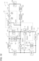
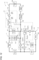
FIG. 1 is a circuit configuration diagram of a cooling system including a cooling module according to the present embodiment. -
FIG. 2 is a perspective view of the cooling module. -
FIG. 3 is an exploded perspective view of the cooling module. -
FIG. 4 is a perspective view of a first housing as viewed from a joining surface side. -
FIG. 5 is an exploded perspective view of the cooling module. -
FIG. 6 is a cross-sectional view taken along the line VI-VI inFIG. 3 . -
FIG. 7 is a perspective view of a lower housing as viewed from a joining surface side. -
FIG. 8 is a cross-sectional view taken along the line VIII-VIII inFIG. 2 . -
FIG. 9 is a diagram showing a first aspect of operation of the cooling system. -
FIG. 10 is a diagram showing a second aspect of the operation of the cooling system. -
FIG. 11 is a diagram showing a third aspect of the operation of the cooling system. -
FIG. 12 is a diagram showing a fourth aspect of the operation of the cooling system. - Hereinafter, one embodiment of a cooling module according to the present invention will be described in detail with reference to the drawings. Note that embodiments described below are examples for describing the present invention, and the present invention is not limited only to these embodiments. Therefore, the present invention can be implemented in various forms without departing from the gist thereof.
- As shown in
FIG. 1 , a cooling system A including acooling module 10 according to the present embodiment includes afirst water pump 1A (an example of a second auxiliary unit), aradiator 1B, an inverter/motor 1C, a DC-DC converter 1D, acharger 1E, areserve tank 1F, asecond water pump 2A (an example of the second auxiliary unit), aheater core 2B, anelectric heater 2D, a water-cooledcondenser 2C, athird water pump 3A (an example of the second auxiliary unit), abattery 3B, achiller 3C, anelectric heater 3D, a first rotary valve 4 (an example of a first auxiliary unit), a second rotary valve 5 (an example of the first auxiliary unit), and a plurality of channels for circulating cooling water (an example of fluid, coolant) therethrough. Among them, thefirst water pump 1A, thesecond water pump 2A, thethird water pump 3A, the firstrotary valve 4, and the secondrotary valve 5 are mounted on thecooling module 10. Meanwhile, theradiator 1B, the inverter/motor 1C, the DC-DC converter 1D, thecharger 1E, thereserve tank 1F, theheater core 2B, theelectric heater 2D, the water-cooledcondenser 2C, thebattery 3B, thechiller 3C, and theelectric heater 3D are disposed spaced apart from thecooling module 10, and are configured such that the cooling water flows therethrough and through thecooling module 10, via a plurality of channels. - The cooling system A is used in an automobile including a motor as a traveling drive source (hereinafter, collectively referred to as an "electric vehicle"), such as, for example, a hybrid electric vehicle (HEV), plug-in hybrid electric vehicle (PHEV), battery electric vehicle (BEV), fuel-cell electric vehicle (FCEV), and circulates the cooling water to cool the inverter/
motor 1C, thebattery 3B, and the like. - The
radiator 1B cools high-temperature cooling water. The inverter/motor 1C is a traveling drive source that operates with electric power supplied from thebattery 3B. The DC-DC converter 1D and thecharger 1E charge thebattery 3B. Theheater core 2B heats air with the high-temperature cooling water to heat a vehicle interior. Theelectric heaters condenser 2C and thechiller 3C are cooled when the temperature of the cooling water is high. Thebattery 3B supplies power to the inverter/motor 1C. - The
first water pump 1A pumps the cooling water to be supplied to the inverter/motor 1C, the DC-DC converter 1D, and thecharger 1E. Thesecond water pump 2A pumps the cooling water to be supplied to theheater core 2B, theelectric heater 2D, and the water-cooledcondenser 2C. Thethird water pump 3A pumps the cooling water to be supplied to thebattery 3B, thechiller 3C, and theelectric heater 3D. Thefirst water pump 1A, thesecond water pump 2A, and thethird water pump 3A control flow of the cooling water flowing through the plurality of channels by pumping the cooling water. - Hereinafter, a circulating channel configured to pass from the
radiator 1B through thefirst water pump 1A, the inverter/motor 1C, the DC-DC converter 1D, thecharger 1E, and thereserve tank 1F and return to theradiator 1B is referred to as a first circulation path 1 (refer toFIG. 9 ), and, of thefirst circulation path 1, a channel formed in thecooling module 10 is referred to as afirst channel 11. Similarly, a circulating channel configured to pass from theheater core 2B through thesecond water pump 2A, the water-cooledcondenser 2C, and theelectric heater 2D and return to theheater core 2B is referred to as a second circulation path 2 (refer toFIG. 9 ), and, of thesecond circulation path 2, a channel formed in thecooling module 10 is referred to as asecond channel 21. Similarly, a circulating channel configured to pass from thebattery 3B through thethird water pump 3A, thechiller 3C, and theelectric heater 3D and return to thebattery 3B is referred to as a third circulation path 3 (refer toFIG. 9 ), and, of thethird circulation path 3, a channel formed in thecooling module 10 is referred to as athird channel 31. Furthermore, a communication channel 51 (an example of a channel) that allows thefirst channel 11, thesecond channel 21 and thethird channel 31 to communicate with each other is formed in thecooling module 10. A channel configuration in thecooling module 10 will be described later. - As shown in
FIGS. 2 to 8 , of the cooling system A, thecooling module 10 includes thefirst water pump 1A, thesecond water pump 2A, thethird water pump 3A, the firstrotary valve 4, the secondrotary valve 5, and a manifold 100 in which channels that allow the cooling water to flow through these components are formed. The manifold 100 is formed by joining and integrating a plurality of housings, thereby forming a plurality of channels through which cooling water flows across at least two housings (in the present embodiment, afirst housing 110 and asecond housing 120 to be described later). Note that, as shown inFIG. 1 , thecooling module 10 does not have a reserve tank therein. Because thecooling module 10 does not include a reserve tank, it is possible to configure thecooling module 10 to be compact and increase flexibility in disposition of thecooling module 10. - The manifold 100 is formed by joining and integrating the
first housing 110 and thesecond housing 120, both made of resin, with a method such as vibration welding. The manifold 100 has a substantially rectangular cuboid shape as a whole, and as shown inFIGS. 3 and4 , a joiningsurface 105 between thefirst housing 110 and thesecond housing 120 has a planar shape. Hereinafter, a direction parallel to a longitudinal direction of the joiningsurface 105 is defined as an X direction, a direction parallel to a widthwise direction of the joiningsurface 105 is defined as a Y direction, and a direction perpendicular to the joiningsurface 105 is defined as a Z direction. That is, the joiningsurface 105 is parallel to an X-Y plane. Moreover, of the X direction, a direction from thefirst water pump 1A toward thethird water pump 3A is defined as an X1 direction, and an opposite direction thereof is defined as an X2 direction. Of the Y direction, a direction from asecond outflow port 115 toward afirst inflow port 111 is defined as a Y1 direction, and an opposite direction thereof is defined as a Y2 direction (thesecond outflow port 115 and thefirst inflow port 111 will be described later.). Of the Z direction, a direction from thesecond housing 120 toward thefirst housing 110 is defined as a Z1 direction, and an opposite direction thereof is defined as a Z2 direction. The Z2 direction is a gravity direction. That is, thefirst housing 110 is disposed on an upper side of thesecond housing 120 in a vertical direction. - As shown in
FIGS. 2 and3 , thefirst housing 110 is formed with thefirst inflow port 111, asecond inflow port 112, athird inflow port 113, afirst outflow port 114, thesecond outflow port 115, and afifth outflow port 116. Furthermore, athird outflow port 121, afourth outflow port 122, and asixth outflow port 123 are formed in thesecond housing 120. All of thefirst inflow port 111, thesecond inflow port 112, thethird inflow port 113, thefirst outflow port 114, thesecond outflow port 115, thethird outflow port 121, thefourth outflow port 122, thefifth outflow port 116, and thesixth outflow port 123 have a cylindrical shape. Thefirst inflow port 111, thesecond inflow port 112, and thethird inflow port 113 are arranged side by side so that axes thereof are along the Z direction and on the same plane, and all of the ports have openings open in the Z1 direction. Thefirst outflow port 114 and thethird outflow port 121 are arranged side by side so that axes thereof are along the X direction and on the same plane, and both the ports have openings open in the X2 direction. Thesecond outflow port 115 and thefifth outflow port 116 are arranged side by side so that axes thereof are along the Y direction and on the same plane, and both the ports have openings open in the Y2 direction. Thefourth outflow port 122 and thesixth outflow port 123 are also arranged side by side such that their axes are along the Y direction and on the same plane, and both the ports have openings in the Y2 direction. - The
first inflow port 111, thefirst outflow port 114, and thesecond outflow port 115 are included in thefirst circulation path 1, and all of the ports communicate with thefirst channel 11. Thesecond inflow port 112 and thefourth outflow port 122 are included in thesecond circulation path 2, and both the ports communicate with thesecond channel 21. Thethird inflow port 113, thefifth outflow port 116, and thesixth outflow port 123 are included in thethird circulation path 3, and all of the ports communicate with thethird channel 31. - As shown in
FIGS. 2 and3 , in the manifold 100, the firstrotary valve 4 and the secondrotary valve 5 are mounted between thefirst inflow port 111, thesecond inflow port 112, and thethird inflow port 113, and thesecond outflow port 115 and thefifth outflow port 116 in thefirst housing 110 when thefirst housing 110 is viewed along the Z2 direction. In the firstrotary valve 4 and the secondrotary valve 5, afirst actuator 4B that rotationally drives afirst valve body 4A of the firstrotary valve 4 and asecond actuator 5B that rotationally drives asecond valve body 5A of the secondrotary valve 5 are exposed on an upper portion of thefirst housing 110. Thefirst valve body 4A and thesecond valve body 5A are both positioned in the second housing 120 (refer toFIG. 6 ). Thus, a flow of the cooling water flowing through the plurality of channels can be controlled by switching between the channels formed in thesecond housing 120. Both the firstrotary valve 4 and the secondrotary valve 5 are an electromagnetic valve that can switch between the channels with an actuator, and rotate thefirst valve body 4A and thesecond valve body 5A about an axis along the Z direction to switch between the channels, thereby controlling the flow of the cooling water flowing through the plurality of channels. Note that thefirst valve body 4A is a three-way valve, and thesecond valve body 5A is a four-way valve. Details will be described later. - As shown in
FIGS. 2 and3 , in the manifold 100, thefirst water pump 1A, thesecond water pump 2A, and thethird water pump 3A are mounted on thesecond housing 120 in this order along the X1 direction. At this time, thefirst water pump 1A, thesecond water pump 2A, and thethird water pump 3A are disposed such that respective rotation axes thereof are along the Y direction. In thesecond housing 120, there are formed a downwardfirst sub-channel 11a (an example of the channel) communicating with thefirst inflow port 111 and extending in the Z direction, a downwardsecond sub-channel 21a (an example of the channel) communicating with thesecond inflow port 112 and extending in the Z direction, and a downwardthird sub-channel 31a (an example of the channel) communicating with thethird inflow port 113 and extending in the Z direction. The downwardfirst sub-channel 11a, the downwardsecond sub-channel 21a, and the downwardthird sub-channel 31a are formed across thefirst housing 110 and thesecond housing 120. Thefirst water pump 1A pumps the cooling water flowing from thefirst inflow port 111 through the downwardfirst sub-channel 11a. Thesecond water pump 2A pumps the cooling water flowing from thesecond inflow port 112 through the downwardsecond sub-channel 21a. Thethird water pump 3A pumps the cooling water flowing from thethird inflow port 113 through the downwardthird sub-channel 31a. Note that the downwardfirst sub-channel 11a is a part of thefirst channel 11, the downwardsecond sub-channel 21a is a part of thesecond channel 21, and the downwardthird sub-channel 31a is a part of thethird channel 31. - As shown in
FIG. 5 , thefirst water pump 1A, thesecond water pump 2A, and thethird water pump 3A are mounted on a mountingportion 125 formed at an end portion (lower end in the vertical direction) of thesecond housing 120 in the Z2 direction. The mountingportion 125 is thicker than other portions of thesecond housing 120. Thus, it is possible to ensure strength of even asecond housing 120 made of resin to be mounted with and hold the heavyfirst water pump 1A, thesecond water pump 2A, and thethird water pump 3A. - In the mounting
portion 125, there are formed a first vortex chamber 1Aa in which the cooling water flowing from the downwardfirst sub-channel 11a into thefirst water pump 1A and discharged by rotation of an impeller (not shown) swirls, a second vortex chamber 2Aa in which the cooling water flowing from the downwardsecond sub-channel 21a into thesecond water pump 2A and discharged by rotation of an impeller swirls, and a third vortex chamber 3Aa in which the cooling water flowing from the downwardthird sub-channel 31a into thethird water pump 3A and discharged by rotation of an impeller swirls Thus, because the first vortex chamber 1Aa, the second vortex chamber 2Aa, and the third vortex chamber 3Aa are formed in the mountingportion 125, shrouds for regulating inflow and outflow directions of the cooling water are not required for thefirst water pump 1A, thesecond water pump 2A, and thethird water pump 3A, and thus, downsizing, weight reduction, and cost reduction of thecooling module 10 is possible. - Thus, because the
cooling module 10 incudes the plurality of channels formed by the manifold 100 extending across thefirst housing 110 and thesecond housing 120, the number of pipes can be reduced. Furthermore, because the manifold 100 is configured by joining thefirst housing 110 and thesecond housing 120, even if shapes and configuration of the channels in the manifold 100 are complicated due to consideration of positions and directions of the ports to which the pipes are connected, a shape of each of thefirst housing 110 and thesecond housing 120 can be simplified. Thus, because the pipes connected to the ports can be integrated to avoid redundant routing, lengths of the pipes connected to the ports can be shortened and simplified. - Next, the flow of the cooling water in the
cooling module 10 will be described with reference toFIGS. 3 and6 to 8 . First, the flow of the cooling water in the first circulation path 1 (refer toFIG. 9 ) will be described. As shown inFIG. 3 , the cooling water cooled by theradiator 1B enters thesecond housing 120 of thecooling module 10 from thefirst inflow port 111, flows through the downwardfirst sub-channel 11a in the Z2 direction, and flows into thefirst water pump 1A. The cooling water pumped by thefirst water pump 1A flows in the Z direction, through an upwardfirst sub-channel 11b (an example of the channel) formed along the Z1 direction, and a lateralfirst sub-channel 11c (an example of the channel) branches from the upwardfirst sub-channel 1 1b at the joiningsurface 105 between thefirst housing 110 and thesecond housing 120. As described above, because thefirst outflow port 114 is formed on thefirst housing 110, the cooling water flowing from thesecond housing 120 to thefirst housing 110 in the Z1 direction through the upwardfirst sub-channel 11b changes a flowing direction in the X2 direction and flows out from thefirst outflow port 114. The cooling water flowing out of thecooling module 10 from thefirst outflow port 114 cools the DC-DC converter 1D and thecharger 1E, and returns to theradiator 1B via thereserve tank 1F (refer toFIG. 1 ). - The lateral
first sub-channel 11c is formed across thefirst housing 110 and thesecond housing 120, and is formed along the Y direction. That is, the lateralfirst sub-channel 11c is formed along the joiningsurface 105 between thefirst housing 110 and thesecond housing 120, and an upper half of the lateralfirst sub-channel 11c is formed in thefirst housing 110 and a lower half thereof is formed in thesecond housing 120. Then, thefirst housing 110 and thesecond housing 120 are joined to each other to form the lateralfirst sub-channel 11c. The cooling water flows through the lateralfirst sub-channel 11c in the Y2 direction and flows out of thecooling module 10 from thesecond outflow port 115 provided at a downstream end of the lateralfirst sub-channel 11c. The cooling water flowing out from thesecond outflow port 115 cools the inverter/motor 1C and returns to theradiator 1B via thereserve tank 1F (refer toFIG. 1 ). Note that the upwardfirst sub-channel 11b and the lateralfirst sub-channel 11c constitute a part of thefirst channel 11. - Next, a flow of the cooling water in the second circulation path 2 (refer to
FIG. 9 ) will be described. As shown inFIG. 3 , the cooling water cooled by theheater core 2B enters thesecond housing 120 of thecooling module 10 from thesecond inflow port 112, flows through the downwardsecond sub-channel 21a in the Z2 direction, and flows into thesecond water pump 2A. The cooling water pumped by thesecond water pump 2A flows in the Z1 direction through an upwardsecond sub-channel 21b formed along the Z direction. A firstspare chamber 4D, which is a space communicating with the upwardsecond sub-channel 21b, is formed at a downstream end of the upwardsecond sub-channel 21b. The firstspare chamber 4D is disposed so as to be adjacent to afirst valve chamber 4C of the firstrotary valve 4 in the Y1 direction. The firstspare chamber 4D communicates with thefirst valve chamber 4C through afirst communication hole 131 opened along the Y direction. By providing the firstspare chamber 4D, it is possible to change the flowing direction of the cooling water flowing through the upwardsecond sub-channel 21b in the Z1 direction to the Y2 direction, and cause the cooling water to flow into thefirst valve chamber 4C from thefirst communication hole 131. Note that thefirst valve chamber 4C and the firstspare chamber 4D are formed across thesecond housing 120 and thefirst housing 110. - As shown in
FIG. 6 , thefirst valve chamber 4C houses thefirst valve body 4A so that thefirst valve body 4A is rotatable about the axis along the Z direction. All the cooling water flowing through the upwardsecond sub-channel 21b flows into thefirst valve chamber 4C through the firstspare chamber 4D and thefirst communication hole 131. Thefirst valve chamber 4C communicates with a lateralsecond sub-channel 21c through asecond communication hole 132 opened along the Y direction, and communicates with afourth channel 41 through athird communication hole 133 opened along the X direction. By rotating thefirst valve body 4A to switch between the channels, the cooling water flowing into thefirst valve chamber 4C flows to either the lateralsecond sub-channel 21c or afourth channel 41. In the state shown inFIG. 6 , the cooling water flows to thefourth channel 41. The lateralsecond sub-channel 21c extends along the Y direction, thefourth channel 41 extends along the X direction, and both the lateralsecond sub-channel 21c and thefourth channel 41 are formed in the second housing 120 (refer toFIG. 3 ). Note that the downwardsecond sub-channel 21a, the upwardsecond sub-channel 21b, the lateralsecond sub-channel 21c, thefirst valve chamber 4C, and the firstspare chamber 4D constitute a part of thesecond channel 21, whereas thefourth channel 41 is not a part of thesecond channel 21 and does not constitute thesecond circulation path 2. - The cooling water flowing from the
first valve chamber 4C into the lateralsecond sub-channel 21c through thesecond communication hole 132 flows in the Y2 direction, and flows out of thecooling module 10 from thefourth outflow port 122. The cooling water flowing out from thefourth outflow port 122 returns to theheater core 2B via the water-cooledcondenser 2C and theelectric heater 2D (refer toFIG. 1 ). The cooling water flowing into thefourth channel 41 from thefirst valve chamber 4C through thethird communication hole 133 flows in the X2 direction and flows out of thecooling module 10 from thethird outflow port 121. The cooling water flowing out from thesecond outflow port 115 flows into theradiator 1B via thereserve tank 1F (refer toFIG. 1 ). The firstrotary valve 4 causes thefirst actuator 4B to rotate thefirst valve body 4A about the axis along the Z direction, thereby causing the cooling water flowing through the upwardsecond sub-channel 21b and flowing into thefirst valve chamber 4C to flow by switching between the lateralsecond sub-channel 21c and thefourth channel 41. - Next, a flow of the cooling water in the third circulation path 3 (refer to
FIG. 9 ) will be described. As shown inFIG. 3 , the cooling water cooled thebattery 3B enters thesecond housing 120 of thecooling module 10 from thethird inflow port 113, flows through the downwardthird sub-channel 31a in the Z2 direction, and flows into thethird water pump 3A. The cooling water pumped by thethird water pump 3A flows in the Z1 direction through an upwardthird sub-channel 31b formed along the Z direction. The secondspare chamber 5D, which is a space communicating with the upwardthird sub-channel 31b, is formed at a downstream end of the upwardthird sub-channel 31b. The secondspare chamber 5D is disposed so as to be adjacent to thesecond valve chamber 5C of the secondrotary valve 5 in the Y1 direction. The secondspare chamber 5D communicates with thesecond valve chamber 5C through afourth communication hole 134 opened along the Y direction. By providing the secondspare chamber 5D, it is possible to change the flowing direction of the cooling water flowing through the upwardthird sub-channel 31b in the Z1 direction to the Y2 direction, and cause the cooling water to flow into thesecond valve chamber 5C from thefourth communication hole 134. Note that thesecond valve chamber 5C and the secondspare chamber 5D are formed across thesecond housing 120 and thefirst housing 110. - As shown in
FIG. 6 , thesecond valve chamber 5C houses thesecond valve body 5A so that thesecond valve body 5A is rotatable about the axis along the Z direction. All the cooling water flowing through the upwardthird sub-channel 31b flows into thesecond valve chamber 5C through the secondspare chamber 5D and thefourth communication hole 134. Thesecond valve chamber 5C communicates with a lateralthird sub-channel 31d through asixth communication hole 136 opened along the Y direction. Furthermore, thesecond valve chamber 5C communicates with a thirdspare chamber 5E and a fourthspare chamber 5F through afifth communication hole 135 and aseventh communication hole 137 respectively, the holes being opened adjacent to each other on both sides in a circumferential direction across thesixth communication hole 136. The thirdspare chamber 5E and the fourthspare chamber 5F are formed across thesecond housing 120 and thefirst housing 110. By rotating thesecond valve body 5A to switch between the channels, the cooling water flowing into thesecond valve chamber 5C flows to any one of the lateralthird sub-channel 31d, the thirdspare chamber 5E, and the fourthspare chamber 5F. In the state shown inFIG. 6 , the cooling water flows to the thirdspare chamber 5E. - As shown in
FIG. 8 , the thirdspare chamber 5E communicates with thefifth outflow port 116 through an L-shaped third sub-channel 31c extending along the Z direction. By providing the thirdspare chamber 5E, it is possible to change the flowing direction of the cooling water, which flows in a direction perpendicular to the Z direction into the thirdspare chamber 5E from thesecond valve chamber 5C through thefifth communication hole 135, to the Z1 direction to cause the cooling water to flow through the L-shapedthird sub-channel 31c and flow out of thecooling module 10 from thefifth outflow port 116. The cooling water flowing out from thefifth outflow port 116 returns to thebattery 3B via theelectric heater 3D (refer toFIG. 1 ). The cooling water flowing from thesecond valve chamber 5C into the lateralthird sub-channel 31d through thesixth communication hole 136 flows in the Y2 direction, and flows out of thecooling module 10 from thesixth outflow port 123. The cooling water flowing out from thesixth outflow port 123 returns to thebattery 3B via thechiller 3C (refer toFIG. 1 ). Note that the downwardthird sub-channel 31a, the upwardthird sub-channel 31b, the L-shapedthird sub-channel 31c, the lateralthird sub-channel 31d, thesecond valve chamber 5C, the secondspare chamber 5D, and the thirdspare chamber 5E constitute a part of thethird channel 31. - As shown in
FIGS. 3 and7 , the fourthspare chamber 5F communicates with thecommunication channel 51 extending in the Z direction from the fourthspare chamber 5F and then bent, extending in the X direction. In thecommunication channel 51, afirst portion 51a extending in the Z direction is formed in thesecond housing 120, and asecond portion 51b extending in the X direction is formed across thefirst housing 110 and thesecond housing 120. That is, thesecond portion 51b of thecommunication channel 51 is formed along the joiningsurface 105 between thefirst housing 110 and thesecond housing 120, and an upper half of thesecond portion 51b is formed in thefirst housing 110 and a lower half of thesecond portion 51b is formed in thesecond housing 120. Thecommunication channel 51 is not a part of thethird channel 31 and does not constitute thethird circulation path 3. - As described above, the
communication channel 51 allowsfirst channel 11,second channel 21, andthird channel 31 to communicate with each other in thecooling module 10. By providing thecommunication channel 51 in this manner, the three circulation paths through which the cooling water circulates can be integrated, and thus the number of pipes connected to the ports can be reduced, and lengths of the pipes can be shortened and simplified. - The
second portion 51b of thecommunication channel 51 is connected to the lateralfirst sub-channel 11c at an end portion opposite to the fourthspare chamber 5F. Furthermore, thesecond portion 51b intersects with the lateralsecond sub-channel 21c when viewed along the Z direction. Thesecond portion 51b is recessed in the Z2 direction to be connected to the lateralsecond sub-channel 21c at the intersection. - The second
rotary valve 5 causes thesecond actuator 5B to rotate thesecond valve body 5A about the axis along the Z direction to cause the cooling water to flow from the upwardthird sub-channel 31b into thesecond valve chamber 5C by switching among three ways that are (1) causing the cooling water to flow from thefifth communication hole 135 through the thirdspare chamber 5E and the L-shapedthird sub-channel 31c, and flow out from thefifth outflow port 116, (2) causing the cooling water to flow from theseventh communication hole 137 through the fourthspare chamber 5F and thecommunication channel 51, and flow out from thesecond outflow port 115, and (3) causing the cooling water to flow from theseventh communication hole 137 through the fourthspare chamber 5F and thecommunication channel 51 and the lateralsecond sub-channel 21c, and flow out from thesecond outflow port 115 and thefourth outflow port 122, and to flow from thesixth communication hole 136 through the lateralthird sub-channel 31d and flow out from thesixth outflow port 123. - Next, a usage of the cooling system A during traveling of the electric vehicle will be described. First, a usage of the cooling system A when the electric vehicle is traveling with a temperature of the cooling system A being extremely low (for example, 0 °C or lower) (hereinafter, referred to as a first aspect) will be described with reference to
FIG. 9 . This corresponds to, for example, a state immediately after the electric vehicle is caused to travel without being warmed up due to an extremely low ambient temperature. At this time, while the inverter/motor 1C, the DC-DC converter 1D, and thecharger 1E need to supply cooled cooling water, theheater core 2B and thebattery 3B need to supply heated cooling water. Therefore, in the first aspect, thefirst circulation path 1, thesecond circulation path 2, and thethird circulation path 3 operate independently. Hereinafter, inFIGS. 9 to 12 , thefirst circulation path 1, thesecond circulation path 2, and thethird circulation path 3 are denoted by thick solid lines. - In the
first circulation path 1, thefirst water pump 1A operates, and the cooling water flowing into thefirst inflow port 111 from theradiator 1B is pumped by thefirst water pump 1A, flows through thefirst channel 11, flows out from thefirst outflow port 114 and thesecond outflow port 115, and returns to theradiator 1B via thereserve tank 1F. Because the cooling water is cooled by theradiator 1B, the inverter/motor 1C, the DC-DC converter 1D, and thecharger 1E are cooled. - In the
second circulation path 2, thesecond water pump 2A is operated, and the firstrotary valve 4 is switched so as to connect thefirst valve chamber 4C and the lateralsecond sub-channel 21c (refer toFIG. 6 ), and the cooling water flowing from theheater core 2B into thesecond inflow port 112 is pumped by thesecond water pump 2A, flows through thesecond channel 21, and flows out from thefourth outflow port 122. The cooling water flowing out from thecooling module 10 is heated by theelectric heater 2D and returns to theheater core 2B. At this time, the water-cooledcondenser 2C does not operate. - In the
third circulation path 3, thethird water pump 3A is operated, and the secondrotary valve 5 is switched so as to connect thesecond valve chamber 5C and the thirdspare chamber 5E (refer toFIG. 6 ), and the cooling water flowing from thebattery 3B into thethird inflow port 113 is pumped by thethird water pump 3A, flows through thethird channel 31, and flows out from thefifth outflow port 116. The cooling water flowing out from thecooling module 10 is heated by theelectric heater 3D and returns to thebattery 3B. Thus, thebattery 3B is warmed by the cooling water. - Next, a usage of the cooling system A when the electric vehicle is traveling with a temperature of the cooling system A being not extremely low, but still low (for example, 0°C to 10°C) (hereinafter, referred to as a second aspect) will be described with reference to
FIG. 10 . This corresponds to, for example, a state where the ambient temperature is extremely low and the electric vehicle travels and slightly warmed up. At this time also, while the inverter/motor 1C, the DC-DC converter 1D, and thecharger 1E need to supply cooled cooling water, theheater core 2B and thebattery 3B need to supply heated cooling water. In the second aspect, thefirst circulation path 1 and thesecond circulation path 2 circulate the cooling water in the same manner as in the first aspect, and thus detailed description thereof will be omitted. - In the
third circulation path 3, thethird water pump 3A is operated, and the secondrotary valve 5 is switched so as to connect thesecond valve chamber 5C and the fourthspare chamber 5F (thesecond valve body 5A is rotated clockwise by 90 degrees from the state shown inFIG. 6 ), and the cooling water flowing from thebattery 3B into thethird inflow port 113 is pumped by thethird water pump 3A, flows into thesecond valve chamber 5C, flows from the fourthspare chamber 5F through thecommunication channel 51, and then flows out from thesecond outflow port 115. At this time, the cooling water flowing through thecommunication channel 51 does not flow into the lateralsecond sub-channel 21c. The cooling water flowing out from thecooling module 10 flows through the inverter/motor 1C, thereserve tank 1F, and theradiator 1B, and returns to thebattery 3B through thechiller 3C. However, thechiller 3C is not operated, and thus the cooling water is not cooled by thechiller 3C. In the second aspect, thefirst circulation path 1 and thethird circulation path 3 integrally circulate the cooling water, and thebattery 3B is warmed by utilizing the cooling water heated by the inverter/motor 1C, the DC-DC converter 1D, and thecharger 1E. Note that the channel connecting theradiator 1B and thechiller 3C is branched in the middle, and some of the cooling water flows to thefirst inflow port 111. Thus, thefirst circulation path 1 of the first aspect is configured. - Next, a usage of the cooling system A when the electric vehicle is traveling with a temperature of the cooling system A being a normal temperature (for example, 10°C to 30°C) that is higher than a low temperature (hereinafter, referred to as a third aspect) will be described with reference to
FIG. 11 . This corresponds to, for example, a state where warm-up has been completed by the electric vehicle traveling (normal traveling state). In the third aspect, thefirst circulation path 1 circulates the cooling water in the same manner as in the first aspect, and thus detailed description thereof will be omitted. Meanwhile, because the operations of thesecond water pump 2A and thethird water pump 3A are stopped, the cooling water does not flow (return) through thesecond circulation path 2 and thethird circulation path 3. - Next, a usage of the cooling system A when the electric vehicle is traveling with a temperature of the cooling system A being higher than the normal temperature (for example, 30°C or higher) (hereinafter, referred to as a fourth aspect) will be described with reference to
FIG. 12 . This corresponds to, for example, a state where the electric vehicle travels for a long time in an environment in which the inverter/motor 1C requires a high torque. At this time, because the inverter/motor 1C, the DC-DC converter 1D, thecharger 1E, and thebattery 3B are in a high temperature state, it is necessary to supply the cooling water to cool them. In the fourth aspect, thefirst circulation path 1 circulates the cooling water in the same manner as in the first aspect, and thus detailed description thereof will be omitted. - In the
second circulation path 2, thesecond water pump 2A is operated, and the firstrotary valve 4 is switched so as to connect thefirst valve chamber 4C and the fourth channel 41 (thefirst valve body 4A is rotated counterclockwise by 90 degrees from the state shown inFIG. 6 ), and the cooling water flowing from theheater core 2B into thesecond inflow port 112 is pumped by thesecond water pump 2A, flows through the upwardsecond sub-channel 21b, thefirst valve chamber 4C, and thefourth channel 41, and then flows out from thethird outflow port 121. As described above, the cooling water flowing out of thecooling module 10 from thethird outflow port 121 flows into theradiator 1B via thereserve tank 1F. The cooling water flowing into theradiator 1B and cooled flows into thefirst inflow port 111 that constitutes thefirst circulation path 1. Then, after being pumped by thefirst water pump 1A, the cooling water flows through the upwardfirst sub-channel 11b, the lateralfirst sub-channel 11c, thecommunication channel 51, and the lateralsecond sub-channel 21c, and flows out of thecooling module 10 from thefourth outflow port 122. Thereafter, the cooling water is cooled by the water-cooledcondenser 2C and returned to theheater core 2B. At this time, theelectric heater 2D is not operated. In the fourth aspect, thesecond circulation path 2 is integrated with thefirst circulation path 1 to circulate and cool the cooling water. At this time, some of the cooling water flowing out from theradiator 1B flows into thechiller 3C. - In the
third circulation path 3, thethird water pump 3A is operated, and the secondrotary valve 5 is switched so as to connect thesecond valve chamber 5C and the lateralthird sub-channel 31d (thesecond valve body 5A is rotated clockwise by 45 degrees from the state shown inFIG. 6 ), and the cooling water flowing from thebattery 3B into thethird inflow port 113 is pumped by thethird water pump 3A, flows into thesecond valve chamber 5C, then flows into the lateralthird sub-channel 31d. - The cooling water flowing into the lateral
third sub-channel 31d flows out from thesixth outflow port 123. The cooling water flowing out from thecooling module 10 returns to thebattery 3B through thechiller 3C. At this time, the cooling water is cooled by thechiller 3C. - Thus, in the
cooling module 10, all the inflow ports are formed along the Z direction, and all the outflow ports are formed along the X direction or the Y direction. In particular, thefirst inflow port 111, thesecond inflow port 112, and thethird inflow port 113 are arranged side by side so that axes thereof are along the Z direction and on the same plane. Furthermore, thefirst outflow port 114 and thethird outflow port 121 are arranged side by side so that axes thereof are along the X direction and on the same plane. Moreover, thesecond outflow port 115 and thefifth outflow port 116 are arranged side by side so that axes thereof are along the Y direction and on the same plane. Thefourth outflow port 122 and thesixth outflow port 123 are also arranged side by side so that axes thereof are along the Y direction and on the same plane. By aligning the orientations and dispositions of the plurality of inflow ports and plurality of outflow ports in this manner, the pipes connected to the inflow port and the outflow port can be integrated to avoid redundant routing, and thus lengths of the pipes in a circuit in the cooling system A can be shortened and simplified. -
- (1) In the present embodiment, the manifold 100, the lateral
first sub-channel 11c, and thecommunication channel 51 are formed by joining the two members, thefirst housing 110 and thesecond housing 120, but the present invention is not limited thereto. At least one of the manifold 100, the lateralfirst sub-channel 11c, and thecommunication channel 51 may be formed by joining three or more members. - (2) In the present embodiment, the
first water pump 1A, thesecond water pump 2A, thethird water pump 3A, the firstrotary valve 4, and the secondrotary valve 5 are used as auxiliary units mounted on thecooling module 10, but the present invention is not limited thereto, and other auxiliary units may be mounted. Other examples of the auxiliary unit include pumps such as a battery pump and a powertrain pump, thechiller 3C, theelectric heaters radiator 1B, and the like. - (3) In the present embodiment, the manifold 100 is provided with channels such as the
first channel 11, thesecond channel 21, thethird channel 31, thefourth channel 41, and thecommunication channel 51, but the present invention is not limited thereto. The number and disposition of the channels including communication paths, positions and opening direction of the inflow/outflow ports, and the number of the inflow/outflow ports in the manifold 100 can be appropriately changed depending on a type and the number of the auxiliary units, and a configuration of the cooling circuit. - The present invention can be utilized in a cooling module.
- 1: First circulation path, 1A: First water pump (second auxiliary unit), 1Aa: First vortex chamber, 1B: Radiator, 2: Second circulation path, 2A: Second water pump (second auxiliary unit), 2Aa: Second vortex chamber, 2B: Heater core, 3: Third circulation path, 3A: Third water pump (second auxiliary unit), 3Aa: Third vortex chamber, 3B: Battery, 4: First rotary valve (first auxiliary unit), 5: Second rotary valve (first auxiliary unit), 10: Cooling module, 11: First channel, 21: Second channel, 31: Third channel, 11a: Downward first sub-channel (channel), 11b: Upward first sub-channel (channel), 11c: First sub-channel (channel), 21a: Downward second sub-channel (channel), 31a: Downward third sub-channel (channel), 51: Communication channel (channel), 100: Manifold, 105: Joining surface, 110: First housing (housing), 111: First inflow port, 112: Second inflow port, 113: Third inflow port, 120: Second housing (housing), and 125: Mounting portion
Claims (8)
- A cooling module not comprising a reserve tank inside, but comprising a manifold made of resin and including a plurality of housings joined to each other, wherein
the manifold includes a plurality of channels formed across at least two of a plurality of the housings. - The cooling module according to claim 1, further comprising a first auxiliary unit and a second auxiliary unit that control flow of fluid flowing through the channels, whereina plurality of the housings include a first housing and a second housing joined to the first housing, andthe first auxiliary unit is mounted on the first housing, and the second auxiliary unit is mounted on the second housing.
- The cooling module according to claim 2, whereinthe first housing is disposed joined to an upper side of the second housing in a vertical direction,the first housing includes a plurality of inflow ports communicating with a plurality of the respective channels, anda plurality of the inflow ports are arranged side by side so that axes of the respective inflow ports are along the vertical direction and on the same plane.
- The cooling module according to claim 3, whereinthe first auxiliary unit is a rotary valve, anda valve body of the rotary valve is positioned in the second housing.
- The cooling module according to any one of claims 2 to 4, whereinthe second housing includes a mounting portion on which the second auxiliary unit is mounted, andthe mounting portion is thicker than other portions.
- The cooling module according to any one of claims 2 to 5, whereinthe second auxiliary unit is a water pump that pumps the fluid, andthe water pump and the second housing constitute a vortex chamber through which pumped the fluid flows.
- The cooling module according to any one of claims 1 to 6, wherein
a plurality of the channels include a first channel that constitutes a part of a first circulation path that circulates through a radiator, a second channel that constitutes a part of a second circulation path that circulates through a heater core, a third channel that constitutes a part of a third circulation path that circulates through a battery, and a communication channel that allows the first channel, the second channel, and the third channel to communicate with one another. - The cooling module according to claim 7, wherein the communication channel is formed along a joining surface of each of a plurality of the housings.
Applications Claiming Priority (1)
| Application Number | Priority Date | Filing Date | Title |
|---|---|---|---|
| PCT/JP2022/027526 WO2024013871A1 (en) | 2022-07-13 | 2022-07-13 | Cooling module |
Publications (2)
| Publication Number | Publication Date |
|---|---|
| EP4484194A1 true EP4484194A1 (en) | 2025-01-01 |
| EP4484194A4 EP4484194A4 (en) | 2025-04-23 |
Family
ID=89536156
Family Applications (2)
| Application Number | Title | Priority Date | Filing Date |
|---|---|---|---|
| EP22951085.4A Pending EP4484194A4 (en) | 2022-07-13 | 2022-07-13 | COOLING MODULE |
| EP23839663.4A Pending EP4484195A4 (en) | 2022-07-13 | 2023-07-12 | Cooling module |
Family Applications After (1)
| Application Number | Title | Priority Date | Filing Date |
|---|---|---|---|
| EP23839663.4A Pending EP4484195A4 (en) | 2022-07-13 | 2023-07-12 | Cooling module |
Country Status (5)
| Country | Link |
|---|---|
| US (2) | US20250220865A1 (en) |
| EP (2) | EP4484194A4 (en) |
| JP (2) | JP7736196B2 (en) |
| CN (2) | CN119365358A (en) |
| WO (2) | WO2024013871A1 (en) |
Families Citing this family (6)
| Publication number | Priority date | Publication date | Assignee | Title |
|---|---|---|---|---|
| WO2025197383A1 (en) * | 2024-03-21 | 2025-09-25 | 株式会社山田製作所 | Cooling module |
| JP2026046203A (en) * | 2024-09-02 | 2026-03-13 | トヨタ自動車株式会社 | Switching device |
| US12650121B2 (en) * | 2024-09-24 | 2026-06-09 | GM Global Technology Operations LLC | Swappable integrated coolant module |
| JP2026069927A (en) | 2024-10-15 | 2026-04-27 | 株式会社アイシン | Cooling module |
| JP2026085675A (en) | 2024-11-13 | 2026-05-25 | 株式会社アイシン | Cooling module |
| JP2026085674A (en) * | 2024-11-13 | 2026-05-25 | 株式会社アイシン | Cooling module |
Family Cites Families (17)
| Publication number | Priority date | Publication date | Assignee | Title |
|---|---|---|---|---|
| DE2033736C3 (en) * | 1970-07-08 | 1978-03-30 | Klaus 7300 Esslingen Huegler | Universal control block for liquid or gaseous media |
| JPH05136305A (en) * | 1991-11-08 | 1993-06-01 | Hitachi Ltd | Cooling device for heating element |
| JPH11220191A (en) * | 1998-01-29 | 1999-08-10 | Miyachi Technos Corp | Solid-state laser device |
| JP2002038949A (en) * | 2000-07-27 | 2002-02-06 | Aisin Seiki Co Ltd | Engine cooling system |
| US9062787B2 (en) * | 2009-04-17 | 2015-06-23 | Mitsubishi Electric Corporation | Valve block, and valve block unit |
| JP2012212768A (en) * | 2011-03-31 | 2012-11-01 | Toyota Industries Corp | Thermoelectric conversion unit |
| JP6265195B2 (en) * | 2015-10-01 | 2018-01-24 | トヨタ自動車株式会社 | Control device for internal combustion engine |
| US10665908B2 (en) | 2016-06-23 | 2020-05-26 | Tesla, Inc. | Heating and cooling reservoir for a battery powered vehicle |
| JP6891565B2 (en) * | 2017-03-16 | 2021-06-18 | 株式会社アイシン | Alignment structure of fluid pressure pump |
| JP6911584B2 (en) * | 2017-07-03 | 2021-07-28 | 株式会社デンソー | Cooling water control valve device |
| FR3069917B1 (en) * | 2017-08-02 | 2020-08-07 | Valeo Siemens Eautomotive France Sas | JOINING COOLING CIRCUIT PORTIONS FOR A SET OF TWO BOXES |
| DE102018102542A1 (en) * | 2018-01-29 | 2019-08-01 | Woco Industrietechnik Gmbh | Apparatus for handling fluids and method for producing the same |
| DE112019001551T8 (en) * | 2018-03-26 | 2021-02-25 | Litens Automotive Partnership | THERMAL MANAGEMENT MODULE FOR VEHICLES |
| WO2020008822A1 (en) * | 2018-07-05 | 2020-01-09 | 日立オートモティブシステムズ株式会社 | Control valve, flow rate control valve, and two-member connecting structure |
| US11572961B2 (en) * | 2020-07-27 | 2023-02-07 | Hanon Systems | Stackable pump and valve coolant modules |
| JP2022061801A (en) * | 2020-10-07 | 2022-04-19 | 株式会社アイシン | Vehicle driving system |
| WO2023141497A1 (en) * | 2022-01-21 | 2023-07-27 | Vitesco Technologies USA, LLC | Multi-port thermal module |
-
2022
- 2022-07-13 EP EP22951085.4A patent/EP4484194A4/en active Pending
- 2022-07-13 WO PCT/JP2022/027526 patent/WO2024013871A1/en not_active Ceased
- 2022-07-13 CN CN202280096269.7A patent/CN119365358A/en active Pending
- 2022-07-13 JP JP2024533387A patent/JP7736196B2/en active Active
- 2022-07-13 US US18/850,841 patent/US20250220865A1/en active Pending
-
2023
- 2023-07-12 EP EP23839663.4A patent/EP4484195A4/en active Pending
- 2023-07-12 US US18/850,786 patent/US20250222760A1/en active Pending
- 2023-07-12 CN CN202380041436.2A patent/CN119233903A/en active Pending
- 2023-07-12 JP JP2024533742A patent/JP7772223B2/en active Active
- 2023-07-12 WO PCT/JP2023/025774 patent/WO2024014491A1/en not_active Ceased
Also Published As
| Publication number | Publication date |
|---|---|
| EP4484195A4 (en) | 2025-06-18 |
| CN119365358A (en) | 2025-01-24 |
| JPWO2024013871A1 (en) | 2024-01-18 |
| WO2024014491A1 (en) | 2024-01-18 |
| EP4484195A1 (en) | 2025-01-01 |
| JP7736196B2 (en) | 2025-09-09 |
| EP4484194A4 (en) | 2025-04-23 |
| US20250222760A1 (en) | 2025-07-10 |
| WO2024013871A1 (en) | 2024-01-18 |
| CN119233903A (en) | 2024-12-31 |
| US20250220865A1 (en) | 2025-07-03 |
| JPWO2024014491A1 (en) | 2024-01-18 |
| JP7772223B2 (en) | 2025-11-18 |
Similar Documents
| Publication | Publication Date | Title |
|---|---|---|
| US20250220865A1 (en) | Cooling module | |
| KR102817287B1 (en) | Coolant suppling module | |
| KR102337225B1 (en) | Integrated thermal management system for vehicle | |
| US20240110630A1 (en) | Multiway valve for an electric vehicle, thermal management system, and method for operating a thermal management system | |
| KR102299300B1 (en) | Integrated Thermal Management Valve For Vehicle | |
| KR20210061158A (en) | Integrated Thermal Management Valve For Vehicle | |
| JP7690662B2 (en) | Battery pack and vehicle | |
| KR102854856B1 (en) | Coolant control module | |
| CN221023255U (en) | Thermal management system and vehicle | |
| EP4484811A1 (en) | Cooling module valve and cooling module | |
| US12486910B2 (en) | Eight-way valve | |
| CN113678303B (en) | Cooling device and housing | |
| KR20220037957A (en) | Water supply module and electronic component cooling system having the same | |
| JP2020167133A (en) | Cooling device and housing | |
| US20250334192A1 (en) | Cooling module | |
| US12543292B2 (en) | Water supply module and electric device cooling system comprising same | |
| KR20230073994A (en) | Water supply module | |
| JP2024125760A (en) | Manifold | |
| US20260061798A1 (en) | Coolant module | |
| US20260132735A1 (en) | Cooling module | |
| US12473967B2 (en) | Oil cooler | |
| KR102950923B1 (en) | Multi port valve apparatus and multi port valve control system | |
| CN122034663A (en) | Cooling module | |
| KR20240135536A (en) | Coolant module | |
| KR20250094992A (en) | Coolant module |
Legal Events
| Date | Code | Title | Description |
|---|---|---|---|
| STAA | Information on the status of an ep patent application or granted ep patent |
Free format text: STATUS: THE INTERNATIONAL PUBLICATION HAS BEEN MADE |
|
| PUAI | Public reference made under article 153(3) epc to a published international application that has entered the european phase |
Free format text: ORIGINAL CODE: 0009012 |
|
| STAA | Information on the status of an ep patent application or granted ep patent |
Free format text: STATUS: REQUEST FOR EXAMINATION WAS MADE |
|
| 17P | Request for examination filed |
Effective date: 20240926 |
|
| AK | Designated contracting states |
Kind code of ref document: A1 Designated state(s): AL AT BE BG CH CY CZ DE DK EE ES FI FR GB GR HR HU IE IS IT LI LT LU LV MC MK MT NL NO PL PT RO RS SE SI SK SM TR |
|
| A4 | Supplementary search report drawn up and despatched |
Effective date: 20250324 |
|
| RIC1 | Information provided on ipc code assigned before grant |
Ipc: B60K 1/00 20060101ALN20250318BHEP Ipc: F01P 7/14 20060101ALN20250318BHEP Ipc: F16K 27/00 20060101ALI20250318BHEP Ipc: H01M 10/60 20140101ALI20250318BHEP Ipc: F01P 7/16 20060101ALI20250318BHEP Ipc: F01P 5/10 20060101ALI20250318BHEP Ipc: B60K 11/02 20060101AFI20250318BHEP |
|
| DAV | Request for validation of the european patent (deleted) | ||
| DAX | Request for extension of the european patent (deleted) |