EP4484076A1 - Computerimplementiertes verfahren, computerimplementiertes werkzeug und robotersteuerungsvorrichtung zur bewegungsplanung von robotermanipulatoren sowie robotersystem - Google Patents
Computerimplementiertes verfahren, computerimplementiertes werkzeug und robotersteuerungsvorrichtung zur bewegungsplanung von robotermanipulatoren sowie robotersystem Download PDFInfo
- Publication number
- EP4484076A1 EP4484076A1 EP23182351.9A EP23182351A EP4484076A1 EP 4484076 A1 EP4484076 A1 EP 4484076A1 EP 23182351 A EP23182351 A EP 23182351A EP 4484076 A1 EP4484076 A1 EP 4484076A1
- Authority
- EP
- European Patent Office
- Prior art keywords
- motion
- robot
- motion planning
- planning
- pmp
- Prior art date
- Legal status (The legal status is an assumption and is not a legal conclusion. Google has not performed a legal analysis and makes no representation as to the accuracy of the status listed.)
- Withdrawn
Links
Images


Classifications
-
- B—PERFORMING OPERATIONS; TRANSPORTING
- B25—HAND TOOLS; PORTABLE POWER-DRIVEN TOOLS; MANIPULATORS
- B25J—MANIPULATORS; CHAMBERS PROVIDED WITH MANIPULATION DEVICES
- B25J9/00—Program-controlled manipulators
- B25J9/16—Program controls
- B25J9/1656—Program controls characterised by programming, planning systems for manipulators
- B25J9/1664—Program controls characterised by programming, planning systems for manipulators characterised by motion, path, trajectory planning
- B25J9/1666—Avoiding collision or forbidden zones
-
- B—PERFORMING OPERATIONS; TRANSPORTING
- B25—HAND TOOLS; PORTABLE POWER-DRIVEN TOOLS; MANIPULATORS
- B25J—MANIPULATORS; CHAMBERS PROVIDED WITH MANIPULATION DEVICES
- B25J9/00—Program-controlled manipulators
- B25J9/16—Program controls
- B25J9/1656—Program controls characterised by programming, planning systems for manipulators
- B25J9/1671—Program controls characterised by programming, planning systems for manipulators characterised by simulation, either to verify existing program or to create and verify new program, CAD/CAM oriented, graphic oriented programming systems
-
- G—PHYSICS
- G05—CONTROLLING; REGULATING
- G05B—CONTROL OR REGULATING SYSTEMS IN GENERAL; FUNCTIONAL ELEMENTS OF SUCH SYSTEMS; MONITORING OR TESTING ARRANGEMENTS FOR SUCH SYSTEMS OR ELEMENTS
- G05B2219/00—Program-control systems
- G05B2219/30—Nc systems
- G05B2219/40—Robotics, robotics mapping to robotics vision
- G05B2219/40395—Compose movement with primitive movement segments from database
-
- G—PHYSICS
- G05—CONTROLLING; REGULATING
- G05B—CONTROL OR REGULATING SYSTEMS IN GENERAL; FUNCTIONAL ELEMENTS OF SUCH SYSTEMS; MONITORING OR TESTING ARRANGEMENTS FOR SUCH SYSTEMS OR ELEMENTS
- G05B2219/00—Program-control systems
- G05B2219/30—Nc systems
- G05B2219/40—Robotics, robotics mapping to robotics vision
- G05B2219/40515—Integration of simulation and planning
Definitions
- the spline motion refers to a movement where the robot manipulator passes through each path point describing a smooth curve.
- the spline motion refers to the movement where the robot manipulator passes through each path point describing a smooth curve.
- a command tool is used specifying path numbers. Thereby multiple path points or position data can be registered to a specified path data set.
- Spline motion uses the specified path data set to pass through each registered path point at a constant speed in a defined order to form a smooth curve. Data saved in advance may be used as path data. This approach allows the motion planner to freely determine a geometric path of the robot manipulator's motion as well as the timing of this motion. The problem now lies in the fact that most robot controllers do not directly support the execution of such externally computed spline-motions.
- a typical approach used today to solve this problem is to program the robot manipulator motions using a "teach in"-concept, i.e. an approach without any automatic planning at all.
- this planning is typically done offline and then this planning is manually reteached on the robot manipulator respectively the robot, i.e. this means automatic planning, but no automatic execution.
- a further approach typically employed in research is to implement custom interpolators for the robot manipulator respectively the robot.
- This approach is very expensive, as many of the features a robot control device is equipped with need to be reverse engineered and re-implemented. These features include safety, real-time requirements, compensation of robot-dynamics and calibration parameters and many more.
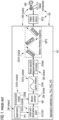
- FIGURE 1 shows - as state of the art - a robotic system RS' for motion planning of a robot manipulator RM based on an application controller AC' such as a "Programmable Logic Controller ⁇ PLC>", a “Process Automation Controller ⁇ PAC>” and an “Industrial Personal Computer ⁇ IPC>”.
- an application controller AC' such as a "Programmable Logic Controller ⁇ PLC>", a “Process Automation Controller ⁇ PAC>” and an “Industrial Personal Computer ⁇ IPC>”.
- motion planning of this robotic system RS' starts with an application APL' which provides an initial point ITP and a destination point DTP for a motion planner MP.
- APL' provides an initial point ITP and a destination point DTP for a motion planner MP.
- the motion planner MP creates a spline motion SPM.
- Motion primitives are basic patterns individually learned by human's motion.
- robot specific approximation of motion RSAM there occur many problems such as
- the motion primitive sequence MPS is inputted by the application controller AC' into a robot control device RCD', which controls according to the inputted motion primitive sequence MPS single motions or movements of a robot manipulator RM'.
- the application controller AC' the robot control device RCD' and the robot manipulator RM' are Hardware ⁇ HW>-related
- the application APL', the motion planner MP and the robot specific approximation of motion RSAM are Software ⁇ SW>-related and the target positions TP, the environment model EVM, the spline motion SPM and the motion primitive sequence MPS are data-related.
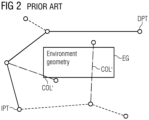
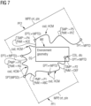
- the solid lines are each a planned motion evaluated by the motion planner and executable on the robot manipulator which due to the given available motion primitives are leading at the end to a planning goal that the robot manipulator is able to move from the starting point SPT to the destination point DPT.
- the dashed lines are each a hypothetical motion evaluated by the motion planner but not necessarily executable on the robot manipulator given by the available motion primitives.
- the dash-dotted lines are each a failed motion evaluated by the motion planner that were rejected due to a collision COL' with the environment geometry EG.
- the objective is further solved based on a computer-implemented tool defined in the preamble of claim 3 by the features in the characterizing part of claim 3.
- the objective is solved furthermore based on a robot control device defined in the preamble of claim 5 by the features in the characterizing part of claim 5.
- the objective is solved moreover based on a robotic system defined in the preamble of claim 6 by the features in the characterizing part of claim 6.
- the idea is based on the usage of a library of motion primitives that the robot manipulator directly supports together with models of how these primitives interpolate the robot manipulator's joints during motion. Then the motion planner can compute a motion in the form of a sequence of primitive motions which can be directly executed.
- the result of the motion planning underlying the invention is not an arbitrary spline motion but instead a sequence of primitive motion commands that are directly supported by the robot manipulator that is supposed to move.
- This set must include three pieces of data for each motion primitive:
- the motion planner creates at least one parametrized, selected primitive motion that leads from the start configuration to the goal configuration. Then the simulated interpolator is used to check the at least one parametrized, selected primitive motion for collisions. If that succeeds, the motion plan is created and can be directly executed on the robot manipulator.
- FIGURES 3 to 7 show:
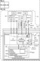
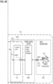
- FIGURE 3 shows an improved (in comparison to the robotic system RS' according to the FIGURE 1 ) robotic system RS for motion planning as an "implementation-concept" to plan pin motions of a robot manipulator RM, which is an essential part of the robotic system RS and operates in work environment WE of the robotic system RS.
- the robotic system RS contains a database DB for storing different data and/or data models being used for the motion planning, which is preferably designed as a local transitory storage medium or a data cloud, and a robot control device RCD as a central component of the robotic system RS including a control unit CU and a robot manipulator interface RMI for controlling the robot manipulator RM.
- the control unit CU is connected via the robot manipulator interface RMI with the robot manipulator RM.
- the control unit CU For executing the motion planning the control unit CU includes according to the "implementation-concept" depicted in the FIGURE 3 a computer-implemented tool CIT is implemented as a sub-unit in the control unit CU.
- the computer-implemented tool CIT is a computer-program-product which is preferably designed as an application software, called as APP, that allows, when it is implemented, to perform special tasks. So, in the present case of the control unit CU, where the computer-program-product respectively the APP is implemented when the APP is loaded into the control unit CU, the computer-implemented tool CIT is used to plan pin the motions of the robot manipulator RM.
- the computer-implemented tool CIT comprises a non-transitory, processor-readable storage medium STM, in which processor-readable program-instructions of a program module PGM for planning robot manipulator motions are stored.
- the program module PGM includes for the motion planning a motion planner component MPC.
- the computer-implemented tool CIT comprises a processor PRC, which connected with the storage medium STM and executing the processor-readable program-instructions executes the motion planner component MPC to plan pin the motions of the robot manipulator RM.
- this is depicted by a dashed drawn lasso around executions of the processor PRC, when executing the motion planner component MPC.
- FIGURE 4 Before going into details about this, an alternative scenario of an improved robotic system RS for motion planning as a "functional-unit-concept" ( FIGURE 4 ) should first be discussed below.
- FIGURE 4 shows alternatively an improved (in comparison to the robotic system RS' according to the FIGURE 1 ) robotic system RS for motion planning as a "functional-unit-concept" to plan pin motions of the robot manipulator RM, which is again the essential part of the robotic system RS and operates in the work environment WE of the robotic system RS.
- the robotic system RS contains the database DB for storing again the different data and/or the data models being used for the motion planning, which is again preferably designed as a local transitory storage medium or a data cloud, and the robot control device RCD as the central component of the robotic system RS including the control unit CU and the robot manipulator interface RMI for controlling the robot manipulator RM.
- the control unit CU is connected again via the robot manipulator interface RMI with the robot manipulator RM.
- the control unit CU For executing the motion planning the control unit CU includes according to the "functional-unit-concept" depicted in the FIGURE 4 the computer-implemented tool CIT forming a functional unit FTU with the control unit CU.
- This functional unit FTU is preferably designed such that the Computer-implemented tool CIT is either loadable (upload) into the control unit CU according to the depiction in the FIGURE 4 or forms either (not depicted in the FIGURE 4 ) a cloud-based, centralized platform, e.g. a cloud server, for the robot control device RCD or a decentralized platform, e.g. a local server, for the robot control device RCD with a mutual access within the functional unit between the control unit CU and the Computer-implemented tool CIT.
- a cloud-based, centralized platform e.g. a cloud server
- a decentralized platform e.g. a local server
- the computer-implemented tool CIT is again the computer-program-product which in the case upload-functionality is again preferably designed as the application software, called as APP, that allows, when it is implemented, to perform special tasks. So, in the present case of the control unit CU, when the computer-program-product respectively the APP is implemented by up-loading the APP into the control unit CU, the computer-implemented tool CIT is being able to plan pin the motions of the robot manipulator RM.
- APP application software
- the computer-implemented tool CIT comprises again the non-transitory, processor-readable storage medium STM, in which the processor-readable program-instructions of the program module PGM for planning robot manipulator motions are stored.
- the program module PGM includes for the motion planning again the motion planner component MPC.
- the computer-implemented tool CIT comprises again the processor PRC, which connected with the storage medium STM and executing the processor-readable program-instructions executes the motion planner component MPC to plan pin the motions of the robot manipulator RM.
- this is depicted again by the dashed drawn lasso around executions of the processor PRC, when executing the motion planner component MPC.
- the motion planning for both concepts, the "implementation-concept” and the “functional-unit-concept”, is generally based on creating crt a motion planning plan MPP on the basis of the different data and/or the data models being stored in the database DB, which are accessed by the processor PRC and thus being inputted into the processor PRC when executing the motion planner component MPC.
- the cited different data and/or the cited data models are including
- the robot manipulator RM is leaded from the start state to the target state when the motion planning plan MPP is executed by the robot control device RCD due to executable control commands CTC being destined and implemented by the robot manipulator RM.
- the cited control commands CTC are preferably script commands SCC.
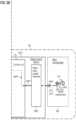
- FIGURE 6 shows starting from the FIGURE 1 and showing in contrast to the state of the art depicted therein the principle of the improved robotic system according to the FIGURES 3 and 4 . It is depicted the improved robotic system RS for motion planning of the robot manipulator RM based on an application controller AC such as a "Programmable Logic Controller ⁇ PLC>", a “Process Automation Controller ⁇ PAC>” and an “Industrial Personal Computer ⁇ IPC>".
- an application controller AC such as a "Programmable Logic Controller ⁇ PLC>", a “Process Automation Controller ⁇ PAC>” and an “Industrial Personal Computer ⁇ IPC>".
- motion planning of this robotic system RS starts with an application APL which provides the starting point STP and the target point TPT positions TP for the motion planner component MPC of the computer-implemented tool CIT.
- APL provides the starting point STP and the target point TPT positions TP for the motion planner component MPC of the computer-implemented tool CIT.
- the motion planning plan MPP is inputted by the application controller AC into the robot control device RCD, which controls according to the motion planning plan MPP single motions or movements of the robot manipulator RM.
- the application controller AC, the robot control device RCD and the robot manipulator RM are Hardware ⁇ HW>-related, the application APL and the motion planner component MPC of the computer-implemented tool CIT are Software ⁇ SW>-related and the starting and target points STP, TPT, the environment model MD, and the motion primitive sequence MPS based motion planning plan MPP are data-related.
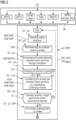
- FIGURE 7 shows two process flows PF1, PF2 for creating the motion planning plan MPP for the work environment WE given by the environment geometry EG of the FIGURE 2 .
- first process flow PF1 it is created crt the motion planning plan MPP, in which it fails to plan pin the motions of the robot manipulator from the starting point SPT to the target point TPT successfully
- second process flow PF2 it is created the motion planning plan MPP, in which it succeeds to plan pin the motions of the robot manipulator RM from the starting point SPT to the target point TPT.
- the second process flow PF2 to plan pin the motions of the robot manipulator from the starting point SPT to the target point TPT successfully.
Landscapes
- Engineering & Computer Science (AREA)
- Robotics (AREA)
- Mechanical Engineering (AREA)
- Manipulator (AREA)
Priority Applications (1)
| Application Number | Priority Date | Filing Date | Title |
|---|---|---|---|
| EP23182351.9A EP4484076A1 (de) | 2023-06-29 | 2023-06-29 | Computerimplementiertes verfahren, computerimplementiertes werkzeug und robotersteuerungsvorrichtung zur bewegungsplanung von robotermanipulatoren sowie robotersystem |
Applications Claiming Priority (1)
| Application Number | Priority Date | Filing Date | Title |
|---|---|---|---|
| EP23182351.9A EP4484076A1 (de) | 2023-06-29 | 2023-06-29 | Computerimplementiertes verfahren, computerimplementiertes werkzeug und robotersteuerungsvorrichtung zur bewegungsplanung von robotermanipulatoren sowie robotersystem |
Publications (1)
| Publication Number | Publication Date |
|---|---|
| EP4484076A1 true EP4484076A1 (de) | 2025-01-01 |
Family
ID=87060270
Family Applications (1)
| Application Number | Title | Priority Date | Filing Date |
|---|---|---|---|
| EP23182351.9A Withdrawn EP4484076A1 (de) | 2023-06-29 | 2023-06-29 | Computerimplementiertes verfahren, computerimplementiertes werkzeug und robotersteuerungsvorrichtung zur bewegungsplanung von robotermanipulatoren sowie robotersystem |
Country Status (1)
| Country | Link |
|---|---|
| EP (1) | EP4484076A1 (de) |
Citations (4)
| Publication number | Priority date | Publication date | Assignee | Title |
|---|---|---|---|---|
| US9811074B1 (en) * | 2016-06-21 | 2017-11-07 | TruPhysics GmbH | Optimization of robot control programs in physics-based simulated environment |
| US10279476B2 (en) * | 2014-06-03 | 2019-05-07 | ArtiMinds Robotics GmbH | Method and system for programming a robot |
| EP3530418A1 (de) * | 2018-02-21 | 2019-08-28 | Siemens Aktiengesellschaft | Verfahren und vorrichtung zum bestimmen eines optimierten bewegungsablaufs einer robotereinrichtung |
| US11235467B2 (en) * | 2018-04-23 | 2022-02-01 | University Of Southern California | System and method for trajectory planning for manipulators in robotic finishing applications |
-
2023
- 2023-06-29 EP EP23182351.9A patent/EP4484076A1/de not_active Withdrawn
Patent Citations (4)
| Publication number | Priority date | Publication date | Assignee | Title |
|---|---|---|---|---|
| US10279476B2 (en) * | 2014-06-03 | 2019-05-07 | ArtiMinds Robotics GmbH | Method and system for programming a robot |
| US9811074B1 (en) * | 2016-06-21 | 2017-11-07 | TruPhysics GmbH | Optimization of robot control programs in physics-based simulated environment |
| EP3530418A1 (de) * | 2018-02-21 | 2019-08-28 | Siemens Aktiengesellschaft | Verfahren und vorrichtung zum bestimmen eines optimierten bewegungsablaufs einer robotereinrichtung |
| US11235467B2 (en) * | 2018-04-23 | 2022-02-01 | University Of Southern California | System and method for trajectory planning for manipulators in robotic finishing applications |
Non-Patent Citations (3)
| Title |
|---|
| KIM SUNG-KYUN ET AL: "Parts assembly planning under uncertainty with simulation-aided physical reasoning", 2017 IEEE INTERNATIONAL CONFERENCE ON ROBOTICS AND AUTOMATION (ICRA), IEEE, 29 May 2017 (2017-05-29), pages 4074 - 4081, XP033127210, DOI: 10.1109/ICRA.2017.7989468 * |
| PHOON MUN SENG ET AL: "Constraint-based Task Specification and Trajectory Optimization for Sequential Manipulation", 2022 IEEE/RSJ INTERNATIONAL CONFERENCE ON INTELLIGENT ROBOTS AND SYSTEMS (IROS), IEEE, 23 October 2022 (2022-10-23), pages 197 - 202, XP034257696, DOI: 10.1109/IROS47612.2022.9981909 * |
| SVEJDA MARTIN ET AL: "Interpolation method for robot trajectory planning", 2015 20TH INTERNATIONAL CONFERENCE ON PROCESS CONTROL (PC), IEEE, 9 June 2015 (2015-06-09), pages 406 - 411, XP033182627, DOI: 10.1109/PC.2015.7169997 * |
Similar Documents
| Publication | Publication Date | Title |
|---|---|---|
| RU2549161C2 (ru) | Способ автономного программирования манипулятора с цифровым управлением | |
| JP6868574B2 (ja) | 産業用ロボットをエンドユーザがプログラミングするための方法とその実行のためのソフトウェアが備えられたプログラム可能なロボット | |
| Suh et al. | A framework for an intelligent CNC and data model | |
| US20190240833A1 (en) | Trajectory generating method, and trajectory generating apparatus | |
| Kovarikova et al. | Prototyping an intelligent robotic welding workplace by a cyber-physic tool | |
| JP2024102220A (ja) | ロボットシステム、タスク生成装置及び制御方法 | |
| Nevliudov et al. | Multithreaded software control of industrial manipulator movement | |
| JPH10124130A (ja) | 組立装置 | |
| EP4484076A1 (de) | Computerimplementiertes verfahren, computerimplementiertes werkzeug und robotersteuerungsvorrichtung zur bewegungsplanung von robotermanipulatoren sowie robotersystem | |
| Carvalho et al. | Off-line programming of flexible welding manufacturing cells | |
| CN119610103B (zh) | 基于机器人运动学的焊缝路径规划方法、系统及介质 | |
| US7570006B2 (en) | Method and means for using a control file with a control unit of a machine | |
| US11826912B2 (en) | Method and control means for controlling a robot assembly | |
| Freund et al. | A system to automate the generation of program variants for industrial robot applications | |
| JP4837837B2 (ja) | 作業ロボットシステムにおけるロボットプログラム作成装置並びに自動制御機器システムのプログラム作成装置。 | |
| Schütz et al. | Virtual commissioning of the trajectory tracking control of a sensor-guided, kinematically redundant robotic welding system on a PLC | |
| Horváth et al. | Supportive robotic welding system for heavy, small series production with non-uniform welding grooves | |
| Filaretov et al. | Human machine interface based on virtual reality for programming industrial robots | |
| CN120677036A (zh) | 用于优化机器人设备绕过障碍物的几何路径的方法 | |
| Miljković et al. | Development of a Domestic 4-axis SCARA Robot | |
| Schmidt et al. | Optimizing welding efficiency: A first approach for an automated mobile welding robot | |
| Bickendorf | Automatic welding robot offline programming with adaptive automation level | |
| US12510882B2 (en) | Method for controlling a plurality of execution mechanisms, electronic device, and storage medium | |
| US12611773B2 (en) | Robot control device, robot control system, and non-transitory computer-readable medium storing a computer program | |
| US20250387913A1 (en) | Method for Determining an Operation to be Performed by a Robot, Method for Determining and Checking an Operation to be Performed by a System, Device for Data Processing, Computer Program, and Computer-Readable Medium |
Legal Events
| Date | Code | Title | Description |
|---|---|---|---|
| PUAI | Public reference made under article 153(3) epc to a published international application that has entered the european phase |
Free format text: ORIGINAL CODE: 0009012 |
|
| STAA | Information on the status of an ep patent application or granted ep patent |
Free format text: STATUS: THE APPLICATION HAS BEEN PUBLISHED |
|
| AK | Designated contracting states |
Kind code of ref document: A1 Designated state(s): AL AT BE BG CH CY CZ DE DK EE ES FI FR GB GR HR HU IE IS IT LI LT LU LV MC ME MK MT NL NO PL PT RO RS SE SI SK SM TR |
|
| STAA | Information on the status of an ep patent application or granted ep patent |
Free format text: STATUS: THE APPLICATION IS DEEMED TO BE WITHDRAWN |
|
| 18D | Application deemed to be withdrawn |
Effective date: 20250702 |