EP4484073A1 - Robot - Google Patents
Robot Download PDFInfo
- Publication number
- EP4484073A1 EP4484073A1 EP23767073.2A EP23767073A EP4484073A1 EP 4484073 A1 EP4484073 A1 EP 4484073A1 EP 23767073 A EP23767073 A EP 23767073A EP 4484073 A1 EP4484073 A1 EP 4484073A1
- Authority
- EP
- European Patent Office
- Prior art keywords
- robot
- link
- robot body
- coupled
- wheel
- Prior art date
- Legal status (The legal status is an assumption and is not a legal conclusion. Google has not performed a legal analysis and makes no representation as to the accuracy of the status listed.)
- Pending
Links
Images








Classifications
-
- B—PERFORMING OPERATIONS; TRANSPORTING
- B62—LAND VEHICLES FOR TRAVELLING OTHERWISE THAN ON RAILS
- B62D—MOTOR VEHICLES; TRAILERS
- B62D57/00—Vehicles characterised by having other propulsion or other ground- engaging means than wheels or endless track, alone or in addition to wheels or endless track
- B62D57/02—Vehicles characterised by having other propulsion or other ground- engaging means than wheels or endless track, alone or in addition to wheels or endless track with ground-engaging propulsion means, e.g. walking members
- B62D57/028—Vehicles characterised by having other propulsion or other ground- engaging means than wheels or endless track, alone or in addition to wheels or endless track with ground-engaging propulsion means, e.g. walking members having wheels and mechanical legs
-
- B—PERFORMING OPERATIONS; TRANSPORTING
- B60—VEHICLES IN GENERAL
- B60G—VEHICLE SUSPENSION ARRANGEMENTS
- B60G17/00—Resilient suspensions having means for adjusting the spring or vibration-damper characteristics, for regulating the distance between a supporting surface and a sprung part of vehicle or for locking suspension during use to meet varying vehicular or surface conditions, e.g. due to speed or load
- B60G17/015—Resilient suspensions having means for adjusting the spring or vibration-damper characteristics, for regulating the distance between a supporting surface and a sprung part of vehicle or for locking suspension during use to meet varying vehicular or surface conditions, e.g. due to speed or load the regulating means comprising electric or electronic elements
- B60G17/0152—Resilient suspensions having means for adjusting the spring or vibration-damper characteristics, for regulating the distance between a supporting surface and a sprung part of vehicle or for locking suspension during use to meet varying vehicular or surface conditions, e.g. due to speed or load the regulating means comprising electric or electronic elements characterised by the action on a particular type of suspension unit
-
- B—PERFORMING OPERATIONS; TRANSPORTING
- B25—HAND TOOLS; PORTABLE POWER-DRIVEN TOOLS; MANIPULATORS
- B25J—MANIPULATORS; CHAMBERS PROVIDED WITH MANIPULATION DEVICES
- B25J11/00—Manipulators not otherwise provided for
- B25J11/008—Manipulators for service tasks
-
- B—PERFORMING OPERATIONS; TRANSPORTING
- B25—HAND TOOLS; PORTABLE POWER-DRIVEN TOOLS; MANIPULATORS
- B25J—MANIPULATORS; CHAMBERS PROVIDED WITH MANIPULATION DEVICES
- B25J19/00—Accessories fitted to manipulators, e.g. for monitoring, for viewing; Safety devices combined with or specially adapted for use in connection with manipulators
- B25J19/0008—Balancing devices
-
- B—PERFORMING OPERATIONS; TRANSPORTING
- B25—HAND TOOLS; PORTABLE POWER-DRIVEN TOOLS; MANIPULATORS
- B25J—MANIPULATORS; CHAMBERS PROVIDED WITH MANIPULATION DEVICES
- B25J19/00—Accessories fitted to manipulators, e.g. for monitoring, for viewing; Safety devices combined with or specially adapted for use in connection with manipulators
- B25J19/005—Accessories fitted to manipulators, e.g. for monitoring, for viewing; Safety devices combined with or specially adapted for use in connection with manipulators using batteries, e.g. as a back-up power source
-
- B—PERFORMING OPERATIONS; TRANSPORTING
- B25—HAND TOOLS; PORTABLE POWER-DRIVEN TOOLS; MANIPULATORS
- B25J—MANIPULATORS; CHAMBERS PROVIDED WITH MANIPULATION DEVICES
- B25J5/00—Manipulators mounted on wheels or on carriages
- B25J5/007—Manipulators mounted on wheels or on carriages mounted on wheels
-
- B—PERFORMING OPERATIONS; TRANSPORTING
- B25—HAND TOOLS; PORTABLE POWER-DRIVEN TOOLS; MANIPULATORS
- B25J—MANIPULATORS; CHAMBERS PROVIDED WITH MANIPULATION DEVICES
- B25J9/00—Program-controlled manipulators
- B25J9/0003—Home robots, i.e. small robots for domestic use
-
- B—PERFORMING OPERATIONS; TRANSPORTING
- B25—HAND TOOLS; PORTABLE POWER-DRIVEN TOOLS; MANIPULATORS
- B25J—MANIPULATORS; CHAMBERS PROVIDED WITH MANIPULATION DEVICES
- B25J9/00—Program-controlled manipulators
- B25J9/0009—Constructional details, e.g. manipulator supports, bases
-
- B—PERFORMING OPERATIONS; TRANSPORTING
- B25—HAND TOOLS; PORTABLE POWER-DRIVEN TOOLS; MANIPULATORS
- B25J—MANIPULATORS; CHAMBERS PROVIDED WITH MANIPULATION DEVICES
- B25J9/00—Program-controlled manipulators
- B25J9/08—Program-controlled manipulators characterised by modular constructions
-
- B—PERFORMING OPERATIONS; TRANSPORTING
- B25—HAND TOOLS; PORTABLE POWER-DRIVEN TOOLS; MANIPULATORS
- B25J—MANIPULATORS; CHAMBERS PROVIDED WITH MANIPULATION DEVICES
- B25J9/00—Program-controlled manipulators
- B25J9/10—Program-controlled manipulators characterised by positioning means for manipulator elements
- B25J9/106—Program-controlled manipulators characterised by positioning means for manipulator elements with articulated links
- B25J9/1065—Program-controlled manipulators characterised by positioning means for manipulator elements with articulated links with parallelograms
-
- B—PERFORMING OPERATIONS; TRANSPORTING
- B25—HAND TOOLS; PORTABLE POWER-DRIVEN TOOLS; MANIPULATORS
- B25J—MANIPULATORS; CHAMBERS PROVIDED WITH MANIPULATION DEVICES
- B25J9/00—Program-controlled manipulators
- B25J9/10—Program-controlled manipulators characterised by positioning means for manipulator elements
- B25J9/12—Program-controlled manipulators characterised by positioning means for manipulator elements electric
-
- B—PERFORMING OPERATIONS; TRANSPORTING
- B60—VEHICLES IN GENERAL
- B60K—ARRANGEMENT OR MOUNTING OF PROPULSION UNITS OR OF TRANSMISSIONS IN VEHICLES; ARRANGEMENT OR MOUNTING OF PLURAL DIVERSE PRIME-MOVERS IN VEHICLES; AUXILIARY DRIVES FOR VEHICLES; INSTRUMENTATION OR DASHBOARDS FOR VEHICLES; ARRANGEMENTS IN CONNECTION WITH COOLING, AIR INTAKE, GAS EXHAUST OR FUEL SUPPLY OF PROPULSION UNITS IN VEHICLES
- B60K1/00—Arrangement or mounting of electrical propulsion units
- B60K1/04—Arrangement or mounting of electrical propulsion units of the electric storage means for propulsion
Definitions
- the present disclosure relates to a robot. More specifically, the present disclosure relates to a robot capable of providing various services according to a user's command input.
- Home robots are robots that perform home tasks on behalf of people, such as helping with housework such as cleaning or controlling home appliances, or robots that act as a user's assistant or provide training to the user using artificial intelligence (AI), robots that replace companion animals, etc.
- AI artificial intelligence
- two-wheeled robots with two wheels have advantages of being easy to store because they occupy a small area of ground and being easily used in homes with a relatively limited space due to a small rotation radius when the robot changes a direction.
- the conventional two-wheeled robots have a limitation that a height of an obstacle at which the robots may pass is set in proportion to sizes of the wheels, and have a limitation that even when passing the obstacle, the robots may be not balanced due to an impact in a process of passing the obstacle, and thus the robot may fall over.
- US Patent Publication No. 2020-0362972A1 (2020.11.19 ) discloses a mobile robot that moves using a pair of legs provided with wheels.
- the mobile robot may move by rotating the wheels provided on the pair of legs in a state of lifting an object using an arm.
- the mobile robot may pass an obstacle by bending or straightening the leg unit having a link structure.
- a body to which the leg unit is coupled is rotated in the form of a pendulum, and a counter-balance is rotated in response to the rotation of the body, thereby maintaining the balance of the mobile robot.
- the mobile robot has a limitation in that the body shakes in a vertical direction while maintaining balance.
- US Patent No. 10010784B1 (2018.07.03 ) discloses a suspension system with wheels.
- the suspension system may have a four-bar linkage structure mounted in a vehicle with one wheel to restrict the wheel to only move upward and downward and absorb an impact by arranging a damper on an end portion of a four-bar linkage.
- the present disclosure has been made in efforts to solve the conventional problems and is directed to providing a robot capable of stably maintaining balance using two wheels.
- the present disclosure is directed to providing a robot capable of passing obstacles with various heights while moving.
- the present disclosure is directed to providing a robot capable of maintaining the balance without shaking in a front-rear or left-right direction while passing an obstacle while moving.
- the present disclosure is directed to providing a robot capable of performing various functions according to a user's needs or circumstances.
- the present disclosure is directed to providing a robot in which a space of a module can be minimized even when the module for performing a function is coupled.
- the present disclosure is directed to providing a robot to which a function in use may be changed to a new function or the new function may be added to the function in use.
- a robot according to the present disclosure may include a robot body in which a motor and a battery are accommodated, a leg unit coupled to each of both side surfaces of the robot body, and a wheel unit rotatably coupled to the leg unit and including a wheel rolling along the ground.
- the leg unit may be disposed on only both side surfaces of the robot body.
- the wheel unit may be disposed vertically above the leg unit.
- a robot according to the present disclosure may include a four-bar linkage including a side frame to which the leg unit is coupled, a first link link-coupled to the side frame, a second link link-coupled to the side frame to which the first link is coupled, and a third link link-coupled to the first link and the second link and coupled to the wheel unit.
- the leg unit may include a gravity compensator configured to generate a rotational force in the link in a direction of lifting the robot body.
- a module coupling space to which a lower functional module may be coupled may be formed between a lower side of the robot body and a pair of leg units.
- An upper functional module may be coupled to an upper side of the robot body.
- the lower functional module may be coupled to the lower side of the robot body.
- An electric wire through hole through which an electric wire passes may be formed in the leg unit.
- the load of the robot body can be vertically concentrated on the wheels by arranging the side frame and the leg unit of the robot body vertically above the pair of wheels.
- the robot of the present disclosure it is possible to pass the obstacle by lifting the wheels when meeting obstacles with various heights using the four-bar linkage structure composed of the side frame, the first link, the second link, and the third link.
- the robot of the present disclosure by arranging the distance between rotation centers of the four-bar link to have the predetermined ratio, even when the wheels are lifted upward while passing the obstacle, the locations of the wheels in the front-rear direction are not changed and the wheels do not shake in the left-right direction, and thus balance can be maintained.
- the robot of the present disclosure it is possible to perform various functions by coupling the upper functional module to the upper side of the robot body or coupling the lower functional module to the lower side of the robot body according to the user's needs or circumstances.
- the robot of the present disclosure it is possible to minimize the space of the lower functional module in the state in which the lower functional module is coupled to the space between the lower portion of the robot body and the pair of leg units and the lower functional module is coupled.
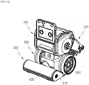
- FIG. 1 is a perspective view for describing a robot according to one embodiment of the present disclosure
- FIG. 2 is an exploded perspective view of FIG. 1
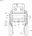
- FIG. 3 is a front view of the robot according to one embodiment of the present disclosure
- FIG. 4 is a rear view of the robot according to one embodiment of the present disclosure
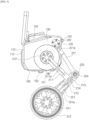
- FIG. 5 is a side view of the robot according to one embodiment of the present disclosure
- FIG. 6 is a bottom view of the robot according to one embodiment of the present disclosure
- FIG. 7 is a view for describing a state in which an upper functional module has been removed from the robot according to one embodiment of the present disclosure.
- a robot 1 according to one embodiment of the present disclosure will be described as follows.
- the robot 1 according to the embodiment of the present disclosure is placed on a floor surface(ground) to move along a floor surface B. Therefore, the following description will be made by setting a vertical direction based on a state in which the robot 1 is placed on the floor.
- a "lowest portion" of each component described in the embodiment of the present disclosure may be a portion of each component that is located to be lowest when the robot 1 according to the embodiment of the present disclosure is used by being placed on the floor, or may be a portion closet to the floor.
- the robot 1 includes a robot body 100, a leg unit 200, and a wheel unit 300.
- the leg unit 200 is coupled to both side surfaces of the robot body 100
- the wheel unit 300 is coupled to the leg unit 200.
- leg unit 100 of the robot 1 according to one embodiment of the present disclosure will be described with reference to FIGS. 1 to 7 as follows.
- the robot body 100 may form an exterior of the robot 1. Components constituting the robot 1 may be coupled to the robot body 100.
- leg unit 200 is coupled to each of frames 130 of both side surfaces of the robot body 100.
- a bumper 112 may be coupled to a front cover 110 provided on a front surface of the robot body 100.
- functional modules 700 and 800 may be detachably coupled to the robot body 100 according to one embodiment of the present disclosure.
- the functional modules 700 and 800 may include the upper functional module 700 coupled to an upper portion of the robot body 100 and the lower functional module 800 coupled to a space between a pair of wheels 310.
- the upper functional module 700 may be detachably coupled to an upper cover 140 disposed at an upper side of the robot body 100.
- the lower functional module 800 may be detachably coupled to a lower cover 150 disposed at a lower side of the robot body 100.
- the robot body 100 may be formed in a shape that has a horizontal width (or a diameter) larger than a vertical height.
- the robot body 100 may assist the robot 1 to have a stable structure and provide a structure that is advantageous in maintaining balance when the robot 1 moves (travels).
- Some components constituting the robot 1 may be accommodated inside the robot body 100.
- an internal space of the robot body 100 may accommodate one or more motors including a suspension motor MS, one or more sensors, and the battery 560.
- the robot body 100 includes a front cover 110.
- the front cover 110 constitutes a front exterior of the robot 1. That is, the front cover 110 may be disposed at the foremost portion of the robot 1 when the robot 1 travels forward.
- the front cover 110 of the robot body 100 may be formed in a flat shape.
- the front cover 110 may have a plate shape with a curved surface.
- the front cover 110 may have a plate shape bent at a predetermined angle.
- the front cover 110 may be provided with a window 111.
- the window 111 may be made of a material through which light may transmit.
- the window 111 may be made of a material through which infrared (IR), visible rays, or ultraviolet (UV) rays may transmit.
- IR infrared
- UV ultraviolet
- the front cover 110 includes an outer surface exposed to the outside of the robot 1 and an inner surface disposed on a back surface of the outer surface.
- the bumper 112 may be coupled to the outer surface of the front cover 110. That is, the bumper 112 may be disposed in front of the robot body 100.
- the bumper 112 may be provided at both end portions of the outer surface of the front cover 110, and a pair of bumpers 112 may be disposed in parallel in a vertical direction.
- the bumper 112 may be provided to move relatively with respect to the robot body 100.
- the bumper 112 may be coupled to the robot body 100 to reciprocate in a front-rear direction of the robot body 100.
- the bumper 112 may be coupled along a portion of a front edge of the front cover 110. Alternatively, the bumper 112 may be coupled along the entire edge of the front cover 110. With this configuration, when the robot 1 collides with another object or person, the bumper 112 can protect the robot body 100 and components accommodated inside the robot body 100 by absorbing an impact applied to the robot body 100.
- the first camera 531 may be disposed behind an inner surface of the front cover 110. Specifically, the first camera 531 may be disposed immediately behind the window 111. With this configuration, the first camera 531 may detect objects or people disposed in front of the robot 1.
- the front cover 110 may include an input unit through which a control command is input from a user, a display unit for visually conveying information about an operating state of the robot 1 to the user, etc.
- the front cover 110 may include a touch screen for visually displaying the operating state of the robot 1 and allowing the control command to be input from the user.
- the robot body 100 includes a rear cover 120.
- the rear cover 120 constitutes a rear exterior of the robot 1.
- the rear cover 120 may be formed in a flat plate shape.
- the rear cover 120 may have a plate shape with a curved surface.
- a manipulation unit 553 for adjusting power of the robot 1 may be disposed on the rear cover 120.
- the manipulation unit 553 may be manipulated by the user, and the robot 1 may be turned on or off by manipulating the manipulation unit 553.
- the manipulation unit 553 may be provided on the rear cover 120 to pivot in a left-right direction or provided to pivot in the vertical direction according to an embodiment.
- the robot 1 when the user pushes one side of the manipulation unit 553 and the manipulation unit 553 pivots to one side, the robot 1 may be turned on. In addition, when the user pushes the other side of the manipulation unit 553 and the manipulation unit 553 pivots to the other side, the robot 1 may be turned off.
- a rear bumper 122 may be coupled to an outer surface of the rear cover 120. That is, the rear bumper 122 may be disposed behind the robot body 100.
- the rear bumper 122 may be provided on the outer surface of the rear cover 120 and may be disposed in the horizontal direction. With this configuration, when the robot 1 collides with another object or person, the bumper 122 can protect the robot body 100 and the components accommodated inside the robot body 100 by absorbing an impact applied to the robot body 100.
- the robot body 100 includes a side frame 130.
- the side frame 130 constitutes the exterior of both side surfaces of the robot 1.
- the side frame 130 may be disposed on each of both side surfaces of the robot 1 and configured to face each other.
- the side frame 130 may be formed in a flat plate shape. That is, both side surfaces of the robot body 100 may be formed in a flat plate shape and disposed in parallel. As another example, at least a portion of the side frame 130 may be formed in a curved shape.
- the side frame 130 is coupled to the front cover 110 and the rear cover 120.
- the side frame 130 may connect the front cover 110 to the rear cover 120.
- the robot body 100 may have an internal space surrounded by the front cover 110, the rear cover 120, and the two side frames 130.
- the leg unit 200 may be disposed outside the side frame 130. Specifically, a first link 210 and a second link 220 may be rotatably coupled to the outside of the side frame 130.
- a support structure is disposed vertically under the robot body to support a load of the robot.
- the support structure is present vertically under the robot body, there is a limitation in that a space under the robot cannot be used.
- the robot 1 according to the embodiment of the present disclosure has the leg unit 200 coupled to the side frame 130.
- the suspension motor MS may be disposed inside the side frame 130.
- Link coupling holes 131 and 132 are formed in the side frame 130.
- the link coupling holes include the first link coupling hole 131 and the second link coupling hole 132.
- the first link coupling hole 131 is formed in a circular hole shape in the side frame 130. At least a portion of the first link 210 may be rotatably accommodated in the first link coupling hole 131. For example, one end portion of the first link 210 may be coupled to a shaft of the suspension motor MS through the first link coupling hole 131.
- the second link coupling hole 132 is formed in a circular hole shape in the side frame 130. At least a portion of the second link 220 may be rotatably accommodated in the second link coupling hole 132. For example, the shaft formed at one side of the second link 220 may be rotatably coupled by passing through the second link coupling hole 132.
- the first link coupling hole 131 may be formed to have a larger diameter than the second link coupling hole 132.
- the first link coupling hole 131 and the second link coupling hole 132 may be formed at a predetermined interval.
- the center of the first link coupling hole 131 in a circular hole shape and the center of the second link coupling hole 132 in a circular hole shape may be disposed at the predetermined interval.
- the first link coupling hole 131 and the second link coupling hole 132 may be disposed at a predetermined inclination with respect to the ground.
- the first link coupling hole 131 may be disposed at a lower side of the side frame 130
- the second link coupling hole 132 may be disposed at an upper rear side of the side frame 130.
- the side frame 130 in which the link coupling holes 131 and 132 are formed may function as a kind of link.
- a handle hole 133 may be formed in the side frame 130.
- the handle hole 133 may be formed at an upper front side of the side frame 130. With this configuration, the user may lift the robot body 100 upward by inserting his/her hand into the handle hole 133 and gripping the side frame 130.
- the upper cover 140 constitutes an upper exterior of the robot 1.
- the upper cover 140 is coupled to the front cover 110, the rear cover 120 and the two side frames 130. Therefore, the upper cover 140 may cover an upper side of the internal space surrounded by the front cover 110, the rear cover 120, and the two side frames 130.
- the upper cover 140 may be disposed to be inclined at a predetermined angle with respect to the ground.
- a front end portion of the upper cover 140 may be disposed closer to the ground than a rear end portion thereof is.
- the upper functional module 700 may be coupled to the upper cover 140.
- the upper functional module 700 may be detachably coupled to an upper side of the upper cover 140.
- a hook accommodation groove 141 may be formed to be hook-coupled to the upper functional module 700 in the upper cover 140.
- the upper functional module 700 may be coupled to the robot body 100 by only a user's simply operation of pushing the hook of the upper functional module 700 into the hook accommodation groove 141.
- the robot body 100 may supply power to the upper functional module 700.
- the upper cover 140 may include a terminal through which power may be supplied to the upper functional module 700.
- the robot body 100 may transmit and receive signals to the upper functional module 700.
- the upper cover 140 may include the terminal through which the signals may be transmitted and received to and from the upper functional module 700.
- the terminal through which power may be supplied to the upper functional module 700 and the terminal through which the signals may be transmitted and received to and from the upper functional module 700 may be disposed together on the upper cover 140.
- the upper cover 140 may include a pogo pin 142 including two power pins and four signal pins.
- At least one guide groove 143 may be formed in the upper cover 140. Alower surface of the upper functional module 700 may be coupled to the guide groove 143. With this configuration, the guide groove 143 may guide a coupling location of the upper functional module 700.
- the lower cover 150 forms a lower exterior of the robot 1.
- the lower cover 150 is coupled to the front cover 110, the rear cover 120, and the two side frames 130. Therefore, the lower cover 150 may cover a lower side of the internal space surrounded by the front cover 110, the rear cover 120, and the two side frames 130.
- the lower functional module 800 may be coupled to the lower cover 150.
- the lower functional module 800 may be detachably coupled to a lower side of the lower cover 150.
- the lower cover 150 may include a coupling bar 151 to be latch-coupled to the lower functional module 800.
- the coupling bar 151 may be formed in a cylindrical shape and disposed in the left-right direction of the robot 1.
- a pair of protrusions connected to the coupling bar 151 may be formed to protrude from the lower cover 150.
- the lower cover 150 may include a charging terminal 152.
- the charging terminal 152 may be disposed on a lower surface of the lower cover 150.
- the charging terminal 152 may be disposed at a location facing the charging terminal provided on a robot charging station (not shown).
- the charging terminal 152 may be electrically connected to a charging terminal provided on the robot charging station (not shown).
- the robot 1 may receive power from the robot charging station (not shown) through the charging terminal 152.
- the power supplied to the charging terminal 152 may be supplied to the battery 560.
- the support structure is disposed vertically under the robot body to support the load of the robot.
- the support structure is present vertically under the robot body, there is a limitation in that a space under the robot cannot be used.
- the robot 1 has the leg unit 200 disposed on both side surfaces of the robot body 100. Therefore, a module coupling space 153 to which the lower functional module 800 is coupled is formed at the lower side of the lower cover 150.
- the module coupling space 153 may be formed between the pair of leg units 200.
- the module coupling space 153 may be a space vertically under the coupling bar 151. That is, the module coupling space 153 may be a space having a predetermined width ⁇ S in the left-right direction.
- the lower functional module 800 is coupled to the space between the lower portion of the robot body 100 and the pair of leg unit 200, thereby minimizing the volume of the robot 1 in the state in which the lower functional module 800 is mounted.
- the robot body 100 may further include an external case.
- the external case may constitute the overall exterior of the robot body 100.
- the external case may cover the exteriors of the front cover 110, the rear cover 120, the side frame 130, the upper cover 140, and the lower cover 150.
- the external case may be formed in an elliptical shape formed to extend in the left-right direction.
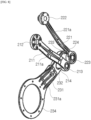
- FIG. 8 is a view for describing a leg unit in the robot according to one embodiment of the present disclosure
- FIG. 9 is a view for describing a connection relationship of the leg unit in the robot according to one embodiment of the present disclosure
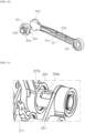
- FIG. 10 is a view for describing a second link in the robot according to one embodiment of the present disclosure
- FIG. 11 is a view for describing a structure for hiding an electric wire in the robot according to one embodiment of the present disclosure.
- leg unit 200 of the robot 1 according to one embodiment of the present disclosure will be described with reference to FIGS. 1 to 11 as follows.
- the leg unit 200 may be coupled to the robot body 100 to support the robot body 100.
- a pair of leg units 200 are provided and are each coupled to the side frame 130 of the robot body 100.
- at least a portion of the leg unit 200 is disposed closer to the ground than the robot body 100. Therefore, the robot body 100 may travel in the form of standing on the ground by the pair of leg units 200. That is, gravity applied to the robot body 100 may be supported by the leg unit 200, and a height of the robot body 100 can be maintained.
- the leg unit 200 is coupled to only both side surfaces of the robot body 100. That is, the leg unit 200 is not coupled to the lower and rear surfaces of the robot body 100.
- a space is formed between the lower side of the lower cover 150 and the pair of leg units 200.
- a space in which a rectangular parallelepiped-shaped lower functional module 800 may be accommodated may be formed between the lower side of the lower cover 150 and the pair of leg units 200.
- the leg unit 200 includes the first link 210, the second link 220, and the third link 230.
- the first link 210 and the second link 220 are rotatably coupled to the side frame 130 and the third link 230, respectively. That is, the first link 210 and the second link 220 are link-coupled to the side frame 130 and the third link 230, respectively.
- the first link 210 is link-coupled to the side surface of the robot body 100.
- the first link 210 may be link-coupled to the side frame 130.
- the first link 210 is connected to the suspension motor MS.
- the first link 210 may be connected to the shaft of the suspension motor MS directly or through a gear. With this configuration, the first link 210 receives a driving force from the suspension motor MS.
- the first link 210 includes a first link body 211, a motor coupling portion 212, and a link coupling portion 213.
- the first link body 211 is formed in a frame shape, the motor coupling portion 212 is provided at one side in a longitudinal direction, and the link coupling portion 213 is provided at the other side in the longitudinal direction. In this case, the motor coupling portion 212 may be disposed farther from the ground than the link coupling portion 213.
- the first link body 211 may be formed in a shape that is bent at least once.
- the other side of the first link body 211 provided with the link coupling portion 213 may be disposed farther from the robot body 100 than the one side provided with the motor coupling portion 212.
- a distance between the pair of first link bodies 211 increases from the top to the bottom in the vertical direction.
- the first link 210 can stably support the robot body 100.
- a rib 211a may be formed on the first link body 211.
- the rib may be formed to protrude from the first link body 211 in the longitudinal direction.
- the rib 211a may be formed in an area in which the first link body 211 is bent. With this configuration, the rib 211a can increase durability by reinforcing the first link 210.
- the motor coupling portion 212 is formed to be connected to one end portion of the first link body 211.
- the motor coupling portion 212 is rotatably accommodated in the first link coupling hole 131 of the side frame 130.
- the motor coupling portion 212 may be formed in a disk shape or a circular plate shape.
- a maximum diameter of the motor coupling portion 212 may be equal to or smaller than a maximum diameter of the first link coupling hole 131. Therefore, the motor coupling portion 212 may be connected to the suspension motor MS through the first link coupling hole 131.
- the motor coupling portion 212 is connected to the suspension motor MS.
- the motor coupling portion 212 is fixedly coupled to the shaft of the suspension motor MS. With this configuration, when the suspension motor MS is driven, the motor coupling portion 212 may be rotated in conjunction with the rotation of the shaft of the suspension motor MS.
- the link coupling portion 213 is formed on the other end portion of the second link body 211.
- the link coupling portion 213 is rotatably coupled to the third link 230.
- the link coupling portion 213 is rotatably coupled to the third link 230 through a first link shaft 214.
- the link coupling portion 213 may be formed in a disk shape, and the first link shaft 214 may be coupled by passing through the center of the link coupling portion 213.
- the first link shaft 214 may be rotatably coupled by passing through the third link 230. With this configuration, the first link 210 and the third link 230 may be connected to rotate relatively.
- the first link shaft 214 is provided to connect the first link 210 to the third link 230.
- the first link shaft 214 may be coupled by passing through the link coupling portion 213 of the first link 210 and/or the third link 230.
- the first link shaft 214 may be rotatably coupled to the link coupling portion 213 and/or the third link 230.
- the first link shaft 214 may be an axis about which the third link 230 rotates.
- a gravity compensator 215 compensates for the robot body 100 that moves down vertically due to gravity. That is, the gravity compensator 215 provides a force for supporting the robot body 100.
- the gravity compensator 215 may be a torsion spring.
- the gravity compensator 215 may be wound to surround an outer circumferential surface of the first link shaft 214.
- one end portion of the gravity compensator 215 is fixedly coupled by being inserted into the first link 210, and the other end portion of the gravity compensator 215 is fixedly coupled by being inserted into the third link 230.
- the gravity compensator 215 applies a force (rotational force) in a direction in which an angle between the first link 210 and the third link 230 increases.
- a force rotational force
- both end portions of the gravity compensator 215 contract in advance to apply a restoring force in a direction in which the angle between the first link 210 and the third link 230 increases. Therefore, even when the robot 1 is placed on the ground and gravity is applied to the robot body 100, the angle between the first link 210 and the third link 230 can be maintained within a predetermined angle range.
- the gravity compensator 215 prevents energy loss due to driving the suspension motor MS and maintains the height of the robot body 100 to a predetermined distance or more from the ground.
- the second link 220 is link-coupled to the side surface of the robot body 100.
- the second link 220 may be link-coupled to the side frame 130. That is, the second link 220 may be coupled to the side frame 130 to which the first link 210 is coupled together.
- the second link 220 includes a second link body 221, a frame coupling portion 222, and a link coupling portion 223.
- the frame coupling portion 222 may be disposed farther from the ground than the link coupling portion 223.
- the second link body 221 is formed in a frame shape, the motor coupling portion 222 is provided at one side in a longitudinal direction, and the link coupling portion 223 is provided at the other side in the longitudinal direction.
- the second link body 221 may be formed in a shape that is bent at least once.
- the other side of the second link body 221 provided with the link coupling portion 223 may be disposed farther from the robot body 100 than the one side provided with the frame coupling portion 222. Therefore, a distance between the pair of second link bodies 221 increases from the top to the bottom in the vertical direction. With this configuration, the second link 220 can stably support the robot body 100.
- the second link body 221 includes an inner surface facing the robot body 100 and an outer surface facing a direction away from the robot body 100.
- a rib 221a may be formed on the second link body 221.
- the rib 221a may be formed to protrude from the outer surface of the second link body 221 in the longitudinal direction.
- the rib 221a may be formed in an area in which the second link body 221 is bent. With this configuration, the rib 221a can increase durability by reinforcing the second link 220.
- An electric wire accommodation wall 221b may be formed on the second link body 221.
- a pair of electric wire accommodation walls 221b may be formed to protrude from the inner surface of the second link body 221 in the longitudinal direction.
- the pair of electric wire accommodation walls 221b may be formed in parallel at a predetermined interval.
- the internal space formed between the pair of electric wire accommodation walls 221b may communicate with an electric wire through hole 222c to be described below.
- the electric wire passing through the electric wire through hole 222c may be accommodated in the internal space formed between the electric wire accommodation walls 221b, thereby preventing the electric wire from being exposed to the outside.
- the second link 220 may be provided with an electric wire support pin 221c.
- the electric wire support pin 221c may pass through the pair of electric wire accommodation walls 221b.
- the electric wire support pin 221c may be disposed in a direction crossing the pair of electric wire accommodation walls 221b.
- the electric wire accommodation wall 221b may close a portion of an open area in the space surrounded by the second link body 221 and the electric wire accommodation walls 221b. Therefore, it is possible to prevent the electric wire from coming out of the space surrounded by the second link body 221 and the electric wire accommodation walls 221b.
- the frame coupling portion 222 is formed on one end portion of the second link body 221.
- the frame coupling portion 222 is rotatably coupled to the second link coupling hole 132 of the side frame 130.
- the frame coupling portion 222 may be provided with a coupling shaft 222a coupled by passing through the side frame 130.
- the coupling shaft 222a may be formed in a cylindrical shape.
- an outer diameter of the other end portion of the coupling shaft 222a may be larger than an outer diameter of one end portion of the coupling shaft 222a coupled to the side frame 130 in an axial direction (longitudinal direction).
- a hollow 222b may be formed in the coupling shaft 222a.
- the electric wire may pass through the hollow 222b.
- the electric wire through hole 222c may be formed in the coupling shaft 222a.
- the electric wire through hole 222c may be formed on an outer circumferential surface of the other end portion of the coupling shaft 222a in the axial direction.
- the coupling shaft 222a may be coupled to a rotational connection plate 222d.
- the rotational connection plate 222d may be formed in a disk shape, and a diameter of the rotational connection plate 222d may be formed to be smaller than a diameter of the other end portion of the coupling shaft 222a in the axial direction. Therefore, the rotational connection plate 222d may be coupled by being accommodated in the other end portion of the coupling shaft 222a in the axial direction.
- the rotational connection plate 222d may be formed integrally with the second link body 221. An outer end portion of the rotational connection plate 222d in a radial direction may be formed to be connected to the second link body 221. With this configuration, the rotational connection plate 222d may couple the second link body 221 to the coupling shaft 222a.
- the link coupling portion 223 is formed on the other end portion of the second link body 221.
- the link coupling portion 223 is rotatably coupled to the third link 230.
- the link coupling portion 223 is rotatably coupled to the third link 230 through a second link shaft 224.
- the link coupling portion 223 may be formed in a disk shape, and the second link shaft 224 may be coupled by passing through the center of the link coupling portion 223.
- the second link shaft 224 may be rotatably coupled by passing through the third link 230. With this configuration, the second link 220 and the third link 230 may be connected to rotate relatively.
- the second link shaft 224 is provided to connect the second link 220 to the third link 230.
- the second link shaft 224 may be coupled by passing through the link coupling portion 223 of the second link 220 and/or the third link 230.
- the second link shaft 224 may be rotatably coupled to the link coupling portion 223 and/or the third link 230.
- the second link shaft 224 may be an axis about which the third link 230 rotates.
- the third link 230 is link-coupled to the first link 210 and the second link 220 and coupled to the wheel unit 300.
- the third link 230 includes a third link body 231.
- the third link body 231 is formed in a frame shape, a third link coupling hole 232 and a fourth link coupling hole 233 are formed at one side thereof in the longitudinal direction, and a wheel coupling portion 234 is formed at the other side in the longitudinal direction.
- the third link body 231 may be formed in a shape that is bent at least once.
- a pair of third link bodies 231 have a distance between the other sides at which the wheel coupling portion 234 is formed, which is shorter than a distance between one sides at which the third link coupling hole 232 and the fourth link coupling hole 233 are formed.
- At least one rib 231a may be formed to protrude from the third link body 231 in the longitudinal direction.
- the rib 231a may be formed in a bent area of the third link body 231. With this configuration, the rib may reinforce the third link body 231.
- the third link coupling hole 232 is formed in the third link body 231. Specifically, the third link coupling hole 232 is formed at one side of the third link body 231 in the longitudinal direction.
- the first link shaft 214 may be rotatably coupled by passing through the third link coupling hole 232.
- the third link coupling hole 232 may be formed in a circular hole shape. With this configuration, the third link 230 may be rotatably connected to the first link 210 through the first link shaft 214.
- a hole into which the gravity compensator 215 is coupled may be formed in the third link body 231.
- the other end portion of the torsion spring may be coupled by being inserted into the hole.
- the fourth link coupling hole 233 is formed in the third link body 231. Specifically, the fourth link coupling hole 233 is formed at one side of the third link body 231 in the longitudinal direction.
- the second link shaft 224 may be rotatably coupled by passing through the fourth link coupling hole 233.
- the fourth link coupling hole 233 may be formed in a circular hole shape. With this configuration, the third link 230 may be rotatably connected to the second link 220 through the second link shaft 224.
- the fourth link coupling hole 233 may be disposed farther from the wheel coupling portion 234 than the third link coupling hole 232.
- the third link 230 is coupled to the wheel unit 300.
- a wheel housing 320 is coupled to an inner surface (surface facing the robot body 100) of the third link body 231, and the wheel 310 is rotatably coupled to an outer surface (back surface of the inner surface) of the third link body 231.
- the wheel coupling portion 234 is formed on the third link body 231. Specifically, the wheel coupling portion 234 is formed at the other side of the third link body 231 in the longitudinal direction.
- the wheel coupling portion 234 may be formed in a circular hole shape.
- the wheel motor MW may be accommodated in the wheel coupling portion 234.
- the wheel coupling portion 234 may be disposed vertically under the robot body 100.
- the wheel coupling portion 234 may be disposed vertically under the suspension motor MS.
- the suspension motor MS is relatively heavy among the components accommodated in the robot body 100. Therefore, the entire weight of the robot body 100 may be concentrated vertically under the suspension motor MS.
- the wheel 310 coupled to the wheel coupling portion 234 can maintain the balance of the robot body 100 by supporting a lower side of the center of gravity of the robot body 100.
- the wheel unit 300 may be rotatably coupled to the leg unit 200 and may roll along the ground to move the robot body 100 and the leg unit 200.
- the wheel unit 300 includes the wheel 310 that is in contact with the ground and rolls along the ground, and the wheel housing 320 in which the wheel motor MW is accommodated.
- the wheel 310 is provided to have a predetermined radius and a predetermined width in the axial direction. As shown in FIG. 3 , when viewing the robot 1 from the front, the side frame 130 and the leg unit 200 may be disposed vertically above the wheel 310.
- the suspension motor MS, the first link coupling hole 131, and the second link coupling hole 132 may be disposed vertically above the wheel 310.
- the wheel 310 includes a wheel frame 311 formed in a circular shape.
- the wheel frame 311 may be formed in a cylindrical shape with an open one side facing the shaft of the wheel motor MW. Therefore, a weight of the wheel frame 311 can be reduced.
- the overall rigidity of the wheel frame 311 can be reduced.
- the rib (not shown) for reinforcing rigidity may be formed on each of the inner and outer surfaces of the wheel frame 311.
- Awheel tire 312 is coupled to an outer circumferential surface of the wheel frame 311.
- the wheel tire 312 may be formed in an annular shape with a diameter of the wheel tire 312 fitted into the outer circumferential surface of the wheel frame 311.
- Grooves of a predetermined pattern may be recessed in the outer circumferential surface of the wheel tire 312 to increase a grip force of the wheel tire 312.
- the wheel tire 312 may be made of an elastic rubber material.
- the wheel housing 320 may have a cylindrical shape with an open one side in the axial direction so that the wheel motor MW is accommodated therein. In this case, a closed portion of the wheel housing 320 may be coupled to an inner surface of the third link 230. With this configuration, it is possible to prevent an external foreign substance from flowing into the wheel housing 320.
- the wheel housing 320 may be provided with a sensor for measuring a distance to the ground.
- the sensor may be a time of flight sensor (ToF sensor).
- a controller 510 may determine whether the wheel 310 is in contact with the ground.
- the wheel 310 is rotatably coupled to the leg unit 200. Specifically, the wheel 310 is rotatably coupled to an outer surface (surface facing the outside of the robot 1) of the third link 230.
- the wheel motor MW may provide a driving force to the wheel 310.
- the wheel motor MW may generate a rotational force by receiving power from the battery 560.
- the wheel motor MW may be accommodated in the wheel housing 320.
- the wheel motor MW may pass through the wheel coupling portion 234 of the third link 230, and the shaft of the wheel motor MW may be coupled to the wheel frame 311 of the wheel 310. That is, the wheel motor MW may be an in-wheel motor.
- the wheel 310 may roll along the ground while rotating, and the robot 1 may move along the ground.
- the upper functional module 700 of the robot 1 will be described with reference to FIGS. 1 to 7 as follows.
- the upper functional module 700 may be detachably coupled to the upper cover 140 of the robot body 100.
- the upper functional module 700 may be provided in various forms according to functions.
- the upper functional module may be a flat plate shape so that an object such as a mobile phone may be placed thereon.
- a wireless charging unit may be provided in the upper functional module.
- the wireless charging unit may charge a mobile phone, etc. mounted on the upper functional module by generating an induction current.
- the upper functional module may have a shape provided with an accommodation groove so that cans, bottles, cups, etc. containing a fluid may be placed thereon and transported.
- a temperature control unit may be provided in the upper functional module.
- the temperature control unit may discharge or absorb heat using electrical energy and cool or warm cans, bottles, cups, etc. accommodated in the upper functional module.
- the upper functional module 700 may be an interaction upper functional module provided to visually and audibly display a response of the robot 1 for emotional interaction with a user.
- the interaction upper functional module 700 may include a display.
- the display may display facial expressions or eye shapes so that the user may feel that he/she is interacting with the robot 1.
- the display of the interaction upper functional module may rotate at a preset angle.
- the upper plate motor 525 may provide a driving force to the display of the interaction upper functional module.
- the upper plate motor 525 may be disposed in the upper functional module. More specifically, a final output stage of a shaft or gear of the upper plate motor 525 is connected to the display.
- the upper plate motor 525 may be rotated by being driven according to a control command of the controller 510, and the display may rotate according to the rotation of the upper plate motor 525.
- the upper functional module 700 may receive power from the robot body 100. Although not shown, the upper functional module 700 may be provided with a terminal that may be electrically connected to the robot body 100.
- the upper functional module 700 may transmit and receive a signal to and from the robot body 100.
- the upper functional module 700 may be provided with a terminal capable of transmitting and receiving the signal to and from the robot body 100.
- a terminal capable of receiving power from the robot body 100 and the terminal capable of transmitting and receiving the signal to and from the robot body 100 may be disposed in the upper functional module 700 together.
- the upper functional module 700 may be provided with a terminal (not shown) at a location facing the pogo pin 142 of the robot body 100.
- FIG. 12 is a view for describing a state in which the robot according to one embodiment of the present disclosure is coupled to the lower functional module
- FIG. 13 is a view for describing a state in which the robot according to one embodiment of the present disclosure approaches the lower functional module to be coupled thereto
- FIG. 14 is a view for describing the lower functional module in the robot according to one embodiment of the present disclosure.
- the robot includes the lower functional module 800.
- the lower functional module 800 is a component coupled to the robot body 100 to provide various functions to the robot 1.
- the lower functional module 800 is detachably coupled to the robot body 100.
- the lower functional module 800 may include a battery (not shown), a suction nozzle 830, and a dust bin 837. With this configuration, when the lower functional module 800 is coupled to the robot body 100, the robot 1 may perform dry cleaning.
- the lower functional module 800 may include a mop that rotates about a rotational axis and a water container for storing water supplied to the mop. With this configuration, when the lower functional module 800 is coupled to the robot body 100, the robot 1 may perform wet cleaning.
- the lower functional module 800 may include an arm and a gripper. With this configuration, when the lower functional module 800 is coupled to the robot body 100, the gripper may grip a mobile phone or a large object and transport the same to another location.
- the lower functional module 800 includes a robot body fastening unit 820 coupled to the robot body 100.
- the robot body fastening unit 820 includes a coupling hook 821 and a corresponding terminal 825.
- the robot body fastening unit 820 may be disposed above a body 810 of the lower functional module 800.
- the lower functional module 800 is coupled to a lower surface of the robot body 100. Specifically, the coupling bar 151 and the charging terminal 152 to be coupled to the lower functional module 800 are disposed on the lower cover 150 of the robot body 100.
- the coupling bar 151 of the lower cover 150 is caught on the coupling hook 821 of the lower functional module 800, and thus the lower functional module 800 is physically coupled to the robot body 100.
- the charging terminal 152 of the lower cover 150 is coupled to a corresponding terminal 825 of the lower functional module 800, and thus the lower functional module 800 is electrically connected to the robot body 100.
- the lower functional module 800 In a state in which the lower functional module 800 is coupled to the robot body 100, the lower functional module 800 is disposed between a pair of leg units. That is, in the state in which the lower functional module 800 is coupled to the robot body 100, the lower functional module 800 is disposed between a pair of wheels 310.
- the robot body 100 may be coupled to the lower functional module 800 when the user's commands or preset conditions are satisfied.
- the robot body 100 may detect a location of the lower functional module 800 and may be coupled to the lower functional module 800 after moving toward the lower functional module 800.
- the robot body 100 may include the lamp 815.
- the lamp 815 may indicate the location of the lower functional module 800 through light emission.
- the lamp 815 may be an infrared (IR) light emitting diode (LED).
- the robot body 100 is provided with an IR sensor 533 to be described below. Therefore, the robot body 100 may detect the light radiated by the lamp 815 and may move toward the lamp 815.
- the first camera 531 may detect the specific location of the lower functional module 800 and a direction in which the lower functional module 800 is placed.
- the robot body 100 may move from the rear to the front of the lower functional module 800 and approach the lower functional module 800.
- the rear of the lower functional module 800 may be a direction in which the lamp 815 is disposed with respect to the corresponding terminal 825.
- the front of the lower functional module 800 may be a direction opposite to the rear (e.g., a direction in which the suction nozzle 830 is disposed).
- the robot body 100 may detect the overall shape of the lower functional module 800, detect the location of the lamp 815, and move in the direction in which the lamp 815 is disposed.
- the robot body 100 may be moved so that a front surface of the robot body 100 passes the ramp 815 and is disposed above the lower functional module 800.
- the robot body 100 may move downward.
- the charging terminal 152 is in contact with the corresponding terminal 825 so that the robot body 100 may be electrically connected to the lower functional module 800.
- the coupling hook 821 is caught on the coupling bar 151 so that the robot body 100 may be physically coupled to the lower functional module 800.
- the lower functional module 800 is disposed between the pair of wheels 310 when coupled to the robot body 100. Specifically, the lower functional module 800 is disposed in the module coupling space 153 formed between the pair of leg units. With this configuration, it is possible to minimize the overall volume of the robot 1 in a state in which the lower functional module 800 is coupled to the robot 1.
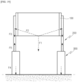
- a virtual vertical line extending upward from a rotation center C5 of the wheel 310 may be disposed between the coupling bar 151 and the charging terminal 152.
- the robot 1 when the lower functional module 800 is coupled to the robot body 100, the overall center of gravity of the robot 1 is lowered, and as an area of the robot 1 in contact with the ground is increased, the robot 1 can stably maintain balance.
- FIG. 15 is a block diagram for describing a control configuration of the robot according to one embodiment of the present disclosure.
- the robot 1 may include the controller 510, a motor unit 520, a sensor unit 530, an interface unit 550, the battery 560, a memory 570, and a communication unit 580.
- the robot 1 described herein may have a larger or fewer number of components than the components listed above.
- the controller 510 may control the overall operation of the robot 1.
- the controller 510 may control the robot 1 to perform various functions according to setting information stored in the memory 570 to be described below.
- the controller 510 may be disposed on the robot body 100. More specifically, the controller 510 may be provided by being mounted on a printed circuit board (PCB) disposed between the left wheel 310 and the right wheel 310.
- PCB printed circuit board
- the controller 510 may include all types of devices capable of processing data, such as a processor.
- processor may be, for example, a data processing device built into hardware, which has a physically structured circuit to perform a function expressed by code or commands included in a program.
- processing devices such as a microprocessor, a central processing unit (CPU), a processor core, a multiprocessor, an application-specific integrated circuit (ASIC), and a field programmable gate array (FPGA) may be included, but the scope of the present disclosure is limited thereto.
- the controller 510 may receive information about an external environment of the robot 1 from at least one component of the sensor unit 530 to be described below.
- the information about the external environment may be, for example, information such as a temperature, humidity, and amount of dust in an interior where the robot 1 travels.
- the information may be, for example, cliff information.
- the information may be, for example, interior map information.
- the information about the external environment is not limited to the above examples.
- the controller 510 may receive information about a current state of the robot 1 from at least one component of the sensor unit 530 to be described below.
- the current state may be, for example, tilt information of the robot body 100.
- the information may be, for example, information about a separation state between the wheel 310 and the ground.
- the information may be, for example, location information of the wheel motor MW.
- the information may be, for example, location information of the suspension motor MS.
- information about the current state of the robot 1 is not limited to the above examples.
- the controller 510 may transmit a driving control command to at least one of components of the motor unit 520 to be described below.
- the rotation of the wheel motor MW may be controlled for the traveling of the robot 1.
- the rotation of the wheel motor MW may be controlled to maintain the horizontal attitude of the robot 1.
- the rotation of the suspension motor MS may be controlled to maintain the horizontal attitude of the robot 1.
- the rotation of the upper plate motor 525 may be controlled to adjust an angle of the upper functional module of the robot 1.
- the controller 510 may receive a user's command through at least one of components of the interface unit 550 to be described below.
- the command may be a command for turning on/off the robot 1.
- the command may be a command for manually controlling various functions of the robot 1.
- the controller 510 may output information related to the robot 1 through at least one of the components of the interface unit 550 to be described below.
- the output information may be visual information.
- the output information may be auditory information.
- the motor unit 520 may include at least one motor and provide a driving force to a component connected to each motor.
- the motor unit 520 may include the wheel motor MW for providing a driving force to the left and right wheels 310. More specifically, the motor unit 520 may include a left wheel motor MW_L for transmitting a driving force to the left wheel 310 and a right wheel motor MW_R for transmitting a driving force to the right wheel 310.
- the wheel motors MW may be disposed in the wheel units 300, respectively. More specifically, the wheel motor MW may be accommodated in the wheel housing 320. The wheel motor MW may be accommodated in the wheel coupling portion 234.
- the wheel motor MW is connected to the wheel 310. More specifically, a final output stage of a shaft or gear of the left wheel motor MW_L is connected to the left wheel 310. A final output stage of a shaft or gear of the right wheel motor MW_R is connected to the right wheel 310.
- Each of the left and right wheel motors MW rotates by being driven according to the control command of the controller 510, and the robot 1 travels along the ground due to the rotation of the wheel 310 according to the rotation of the wheel motor MW.
- the motor unit 520 may include the suspension motor MS for providing a driving force to the left and right leg units 200. More specifically, the motor unit 520 may include a left suspension motor MS_L for transmitting a driving force to the left leg unit 200 and a right suspension motor MS_R for transmitting a driving force to the right leg unit 200.
- the suspension motor MS may be disposed on the robot body 100. More specifically, the suspension motor MS may be disposed inside each of the side frames 130.
- the suspension motor MS is connected to the first link 210. More specifically, a final output stage of a shaft or gear of the left suspension motor MS_L is connected to the left first link 210. A final output stage of a shaft or gear of the right suspension motor MS_R is connected to the right first link 210.
- Each of the left and right suspension motors MS rotates by being driven according to the control command of the controller 510, and as the first link 210 rotates according to the rotation of the suspension motor MS and the third link 230 connected to the first link 210 rotates, as a result, the wheel 310 connected to the third link 230 moves upward or downward.
- the robot 1 may lift or lower the wheel 310 and maintain a horizontal attitude when climbing an obstacle or traveling along a curved ground.
- the motor unit 520 may include the upper plate motor 525 for providing a driving force to the upper functional module.
- the upper plate motor 525 may be a servo motor.
- the servo motor is a well-known motor used where rotation angle control is required and has a limited operating range but has an advantage in that accurate position control is possible.
- the upper plate motor 525 may provide a driving force to the display of the interaction upper functional module.
- the upper plate motor 525 may be disposed in the upper functional module. More specifically, a final output stage of a shaft or gear of the upper plate motor 525 is connected to the display.
- the upper plate motor 525 may be rotated by being driven according to a control command of the controller 510, and the display may rotate according to the rotation of the upper plate motor 525.
- the sensor unit 530 may include at least one sensor, and each sensor may measure or detect information about an external environment of the robot 1 and/or information about a current state of the robot 1.
- the sensor unit 530 may include the first camera 531.
- the first camera 531 may be a mapping camera.
- the first camera 531 is provided to map an interior in which the robot 1 travels.
- the first camera 531 may be disposed in front of the robot body 100. More specifically, the first camera 531 may be disposed behind the inner surface of the front cover 110. The first camera 531 may be disposed behind the window 111.
- the first camera 531 may photograph the interior while traveling to perform simultaneous localization and mapping (SLAM).
- the controller 510 may implement the SLAM based on information about the surrounding environment photographed by the first camera 531 and information about the current location of the robot 1.
- a method in which the robot 1 according to the embodiment of the present disclosure implements the SLAM may be a method implemented using only the first camera 531, but is not limited thereto.
- the robot 1 may implement the SLAM further using an additional sensor.
- the additional sensor may be, for example, a laser distance sensor (LDS).
- the sensor unit 530 may include a second camera 532.
- the second camera 532 is a component provided to recognize a user's location and/or face.
- the second camera 532 may be disposed in the upper functional module. More specifically, the second camera 532 may be disposed adjacent to the display of the upper functional module. The second camera 532 may be disposed on an upper portion of the display. The second camera 532 may be disposed between left and right speakers 552.
- the second camera 532 may recognize the user's location by capturing a forward image of the display. To this end, the second camera 532 may include a depth module and an RGB module.
- the depth module may acquire depth information of the image.
- the depth information may be obtained in a manner of acquiring moving time information by measuring a retardation or phase shift of a modulated optical signal for all pixels of the captured image.
- the RGB module may acquire color images (images). Edge characteristics, color distribution, frequency characteristics or wavelet transform, etc. may be extracted from the color images.
- whether a user is present in front or the user's location may be recognized by acquiring distance information about an object to be recognized through the depth information from the forward image captured by the second camera 532 and calculating the edge characteristics, etc. extracted from the color images together.
- the sensor unit 530 may include an IR sensor 533 for detecting infrared rays.
- the IR sensor 533 may be an IR camera for detecting infrared rays.
- the IR sensor 533 may be disposed on the robot body 100. More specifically, the IR sensor 533 may be disposed behind the inner surface of the front cover 110. The IR sensor 533 may be disposed behind the window 111. The IR sensor 533 may be disposed in a left-right direction or vertical direction from the first camera 532.
- the robot may approach the module by allowing the IR sensor 533 to detect infrared rays emitted by an IR LED provided in a specific module.
- the module may be a charging station for charging the robot 1.
- the module may be a lower functional module detachably provided on the lower cover 150 of the robot 1.
- the controller 510 may control the IR sensor 533 to start detecting the IR LED when a charging state of the robot 1 is a preset level or less.
- the controller 510 may control the IR sensor 533 to start detecting the IR LED when a command to find a specific module is received from a user.
- the sensor unit 530 may include a wheel motor sensor 534.
- the wheel motor sensor 534 may measure the location of the wheel motor MW.
- the wheel motor sensor 534 may be an encoder.
- the encoder may detect the location of the motor and also detect a rotational speed of the motor.
- the wheel motor sensor 534 may be disposed on each of the left and right wheel motors MW. More specifically, the wheel motor sensor 534 may be connected to the final output end of the shaft or gear of the wheel motor MW and accommodated inside the wheel housing 320 together with the wheel motor MW.
- the sensor unit 530 may include an upper plate motor sensor 535.
- the upper plate motor sensor 535 may measure a rotation angle of the display of the interaction upper functional module 700.
- the upper plate motor sensor 535 may be a potentiometer for measuring a rotation angle.
- the upper plate motor sensor 535 may be disposed in the interaction upper functional module 700. More specifically, the upper plate motor sensor 535 may be connected to the final output stage of the shaft or gear of the upper plate motor 525 and disposed behind the display together with the upper plate motor 525.
- the sensor unit 530 may include a tilt detection sensor 536.
- the tilt detection sensor 536 may measure a tilt angle of the robot body 100.
- the tilt detection sensor 536 may be, for example, a three-axis acceleration sensor.
- the acceleration sensor is a sensor for detecting a gravitational acceleration of an object in a stationary state. Since the gravitational acceleration varies depending on a tilt angle of the object, the tilt angle is obtained by measuring the gravitational acceleration.
- a correct value cannot be obtained in a moving acceleration state rather than a stationary state.
- the tilt detection sensor 536 may be, for example, a three-axis gyro sensor.
- the gyro sensor is a sensor for measuring an angular velocity. A tilt angle is obtained by integrating the angular velocity over the entire time.
- continuous errors occur in the angular velocity measured by the gyro sensor due to noise and other reasons, and due to these errors, an error in an integral value accumulatively occurs over time.
- the tilt of the robot 1 may be accurately measured by the acceleration sensor, but an error is caused by the gyro sensor. While traveling, an accurate tilt value of the robot 1 may be measured using the gyro sensor, but a correct value cannot be obtained using the acceleration sensor.
- the tilt detection sensor 536 may be an inertial measurement unit (IMU) sensor.
- IMU inertial measurement unit
- the IMU sensor is a sensor in which a three-axis acceleration sensor, a three-axis gyro sensor, and a geomagnetic sensor are embedded together and is also referred to as an inertial measurement sensor.
- the disadvantages of the above-described acceleration sensor and gyro sensor may be compensated using the IMU sensor.
- the IMU sensor is provided as the tilt detection sensor 536.
- the IMU sensor may be disposed on the robot body 100. More specifically, the IMU sensor may be disposed adjacent to the controller 510. The IMU sensor may be provided by being mounted on a PCB inside the robot body 100. To increase the measurement accuracy of the tilt angle and direction, the IMU sensor is preferably disposed close to a central area of the robot body 100.
- the IMU sensor may measure at least one of the three-axis acceleration, the three-axis angular velocity, and the three-axis geomagnetic data of the robot body 100 and transmit the same to the controller 510.
- the controller 510 may calculate the tilted direction and angle of the robot body 100 using at least one of the acceleration, angular velocity, and geomagnetic data received from the IMU sensor. Based on the same, the controller 510 may perform control of maintaining the horizontal attitude of the robot body 100 to be described below.
- the sensor unit 530 may include a fall prevention sensor 537 for detecting a cliff.
- the fall prevention sensor 537 may be configured to detect a distance to the ground in front of the robot 1 along which it travels.
- the fall prevention sensor 537 may be configured in various ways within a range in which a relative distance between a point at which the fall prevention sensor 537 is formed and the ground may be detected.
- the fall prevention sensor 537 may include a light emitting unit for emitting light and a light receiving unit for receiving reflected light.
- the fall prevention sensor 537 may be configured as an infrared sensor.
- the fall prevention sensor 537 may be referred to as a cliff sensor.
- the fall prevention sensor 537 may be disposed on the robot body 100. More specifically, the fall prevention sensor 537 may be disposed inside the front cover 110 of the robot body 100. Preferably, the fall prevention sensor 537 may be disposed inside a downward slope provided on the front cover 110. Therefore, the fall prevention sensor 537 may radiate light toward a front floor surface of the robot 1. That is, the fall prevention sensor 537 disposed inside the front slope may detect in advance whether a cliff is present in front of the robot 1 in a proceeding direction.
- the light emitting unit of the fall prevention sensor 537 may radiate light obliquely toward the front floor surface.
- the light receiving unit of the fall prevention sensor 537 may receive light incident by being reflected from the floor surface.
- a distance between the front ground and the fall prevention sensor 537 may be measured based on a difference between a radiation time point and a reception time point of light.
- the controller 510 may control the wheel motor MW so that the robot 1 travels while avoiding the detected cliff.
- control of the wheel motor MW may be stop control.
- control of the wheel motor MW may be change control of a rotation direction.
- the fall prevention sensor 537 may be additionally disposed inside the rear cover 120 of the robot body 100.
- the fall prevention sensor 537 may be disposed inside a downward slope provided on the rear cover 120. Therefore, the fall prevention sensor 537 may radiate light toward a rear floor surface of the robot 1. That is, the fall prevention sensor 537 disposed inside the rear slope may detect in advance whether a cliff is present behind the robot in a proceeding direction.
- the sensor unit 530 may include a contact detection sensor 538.
- the contact detection sensor 538 may detect whether the wheel 310 has been in contact with the ground.
- the contact detection sensor 538 may include a time of flight (TOF) sensor 538a for measuring a separation distance between the wheel 310 of the robot 1 and the ground.
- the TOF sensor 538a may be a three-dimensional (3D) camera to which a TOF technology is applied.
- the TOF technology is a technology of measuring a distance to an object based on a round-trip flight time in which light radiated toward the object is reflected and returned.
- the TOF sensor 538a may be disposed on the wheel unit 300.
- the contact detection sensor 538 may be disposed on each of the left and right wheel housings 320. Whether the wheel 310 is in contact with the ground may be determined through the distance to the ground measured by the TOF sensor 538a.
- the distance measured by the TOF sensor 538a is less than a preset distance (or less than the lower limit of a preset distance range)
- the wheel 310 is in a state of being in contact with the ground.
- the distance measured by the TOF sensor 538a is the preset distance or more (or the upper limit or more of the preset distance range)
- the wheel 310 is in a state of being spaced from the ground.
- the contact detection sensor 538 may include a load cell 538b that measures a magnitude of a force applied to some components of the robot 1.
- a resistance value of a strain gauge provided on the surface changes.
- the magnitude of the force applied to the load cell 538b may be measured by changing the resistance value.
- the load cell 538b may be disposed on the leg unit 200.
- the load cell 538b may be disposed on each of the left and right third link bodies 231. While the wheel 310 is in a state of being in contact with the floor, the third link 230 is deformed by applying a normal force from the ground. A measured value of the load cell 538b is shown as a value different from an initial value depending on the deformation of the third link 230. Therefore, it may be determined whether the wheel 310 is in a state of being in contact with the ground.
- the sensor unit 530 may include an environmental sensor 539.
- the environmental sensor 539 may be configured to measure various environmental states outside the robot 1, that is, at home in which the robot 1 travels.
- the environmental sensor 539 may include at least one of a temperature sensor 539a, a humidity sensor 539b, and a dust sensor 539c.
- the environmental sensor 539 may be disposed on the robot body 100. More specifically, the environmental sensor 539 may be disposed behind the robot body 100. As a possible embodiment, information measured by the environmental sensor 539 may be visually displayed on a display unit 554.
- the interface unit 550 may include at least one component for interaction between the user and the robot 1, and each component may be provided to input a command from the user and/or output information to the user.
- the interface unit 550 may include a microphone 551.
- the microphone 551 is a component for recognizing the user's voice and may be provided in plural.
- the microphone 551 may be disposed in the upper functional module 700. More specifically, the microphone 551 may be disposed in the interaction upper functional module 700.
- the microphone 551 may be disposed adjacent to the display of the interaction upper functional module 700. Preferably, a total of four microphones 551 may be disposed with two microphones disposed on each of upper and lower portions of the display.
- a voice signal received by the microphone 551 may be used to track the user's location.
- a known sound source tracking algorithm may be applied.
- the sound source tracking algorithm may be a three-point measurement method (triangulation method) using a time difference in which a plurality of microphones 551 receive voice signals. The principle is that a location of the voice source is calculated using a location of each microphone 551 and a speed of a sound wave.
- the robot 1 may be implemented to find the user's location even when the user calls the robot 1 from a distance.
- the interface unit 550 may include a speaker 552.
- the speaker 552 may be disposed in the upper functional module 700.
- the speaker 552 may be disposed adjacent to the display of the interaction upper functional module 700.
- the speaker 552 may be disposed on the upper portion of the display and provided at each of left and right sides thereof.
- the speaker 552 may transmit information about the robot 1 as sound.
- the source of the sound transmitted by the speaker 552 may be sound data previously stored in the robot 1.
- the pre-stored sound data may be voice data of the robot 1.
- the pre-stored sound data may be a notification sound that guides the state of the robot 1.
- the interface unit 550 may include the manipulation unit 553.
- the manipulation unit 553 may receive a command that controls the power of the robot 1 to be turned on/off from the user.
- a power-on operation may mean supplying power to the controller 510.
- a power-off operation may mean cutting-off the power supply to the controller 510. The power is suppled from the battery 560.
- the power-off of the robot 1 through the manipulation unit 553 may mean complete power cutoff and have a different meaning from a power saving mode that temporarily stops power supply to each functional module. Control of the power saving mode may be performed by the controller 510 in a power-on state.
- the manipulation unit 553 is disposed behind the robot body 100.
- the user's command to the manipulation unit 553 may be an operation of pivoting the manipulation unit 553 in the vertical direction or left-right direction.
- the robot 1 When the manipulation unit 553 is pivoted to one side by the user, the robot 1 may be turned on.
- the robot 1 When the manipulation unit 553 is pivoted by the user to the other side opposite to the one side, the robot 1 may be turned off.
- the manipulation unit 553 may be a button for receiving an on/off command through the user's push operation.
- the manipulation unit 553 may be a sliding button for receiving the on/off command through the user's sliding operation.
- the manipulation unit 553 may be a touch screen for receiving the on/off command through the user's touch operation.
- the interface unit 550 may include the display unit 554 and an input unit 555.
- the display unit 554 may include a display disposed in one or more modules.
- the display unit 554 may include a first display disposed on the front cover 110 of the robot body 100.
- the display unit 554 may include a second display disposed in the upper functional module 700.
- the first and second displays may be formed as any one of a light emitting diode (LED), a liquid crystal display (LCD), a plasma display panel, and an organic light emitting diode (OLED).
- LED light emitting diode
- LCD liquid crystal display
- OLED organic light emitting diode
- Information such as operating time information of the robot 1 and power information of the battery 560 may be displayed on the first display or the second display.
- the facial expression of the robot 1 may be displayed on the second display.
- the eyes of the robot 1 may be displayed on the second display.
- the current state of the robot 1 may be expressed by being personified as emotions through a facial shape or eye shape displayed on the second display. For example, when the user returns home after going out, a smiling facial expression or smiling eye shape may be displayed on the second display. Therefore, the user may feel the interaction with the robot 1.
- the input unit 555 may be configured to receive a control command for controlling the robot 1 from the user.
- the control command may be a command for changing various settings of the robot 1.
- the settings may be voice volume, display brightness, power saving mode settings, etc.
- the input unit 555 may be disposed on the front cover 110 of the robot body 100.
- the input unit 555 may be disposed adjacent to or on the first display.
- the input unit 555 generates key input data input by the user to control the operation of the robot 1.
- the input part 555 may be composed of a key pad, a dome switch, a touch pad (static pressure/electrostatic), etc.
- the touch pad forms a layered structure with the first display, this may be referred to as a touch screen.
- the battery 560 is configured to supply power to other components constituting the robot 1.
- the battery 560 may be disposed on the robot body 100. More specifically, the battery 560 may be disposed at the rear side of the robot body 100. The battery 560 may be disposed behind the suspension motor MS.
- the battery 560 may be charged by an external power source, and to this end, a charging terminal 152 for charging the battery 560 may be provided at one side of the robot body 100 or on the battery 560.
- the charging terminal 152 may be disposed on the lower cover 150 of the robot body 100. Therefore, the robot 1 may be easily coupled to the charging station in a manner of approaching the charging station and seating the charging terminal 152 on the corresponding terminal of the charging station from the top.
- the memory 570 is a component for storing various pieces of data for driving and operating the robot 1.
- the memory 570 may store an application program and various pieces of data for autonomous driving of the robot 1.
- the memory 570 may also store pieces of data sensed by the sensor unit 530 and setting information for various settings selected or input by the user.
- the memory 570 may include magnetic storage media or flash storage media, but the scope of the present disclosure is not limited thereto.
- the memory 570 may include an internal memory and/or an external memory and include volatile memories such as DRAMs, SRAMs, or SDRAMs, non-volatile memories such as one time programmable ROMs (OTPROMs), PROMs, EPROMs, EEPROMs, mask ROMs, flash ROMs, NAND flash memories, or NOR flash memories, flash drives such as SSD, compact flash (CF) cards, SD cards, Micro-SD cards, Mini-SD cards, XD cards, or memory sticks, or storage devices such as HDDs.
- volatile memories such as DRAMs, SRAMs, or SDRAMs
- non-volatile memories such as one time programmable ROMs (OTPROMs), PROMs, EPROMs, EEPROMs, mask ROMs, flash ROMs, NAND flash memories, or NOR flash memories
- flash drives such as SSD, compact flash (CF) cards, SD
- the memory 570 may be included in the controller 510 or provided as a separate component.
- the communication unit 580 may be provided to transmit signals between internal components of the robot 1.
- the communication unit 580 may support, for example, controller area network (CAN) communication.
- the signals may be, for example, control commands transmitted from the controller 510 to another component.
- CAN controller area network
- the communication unit 580 may support wireless communication with other devices present outside the robot 1.
- a short-range communication module or a long-distance communication module may be provided as a wireless communication module for supporting wireless communication.
- the short-distance communication may be, for example, Bluetooth communication, near field communication (NFC), etc.
- the long-distance communication may be, for example, Wireless LAN (WLAN), Digital Living Network Alliance (DLNA), Wireless Broadband (Wibro), World Interoperability for Microwave Access (WiMAX), Global System for Mobile communication (GSM), Code Division Multi Access (CMDA), CDMA2000, Enhanced Voice-Data Optimized or Enhanced Voice-Data Only (EV-DO), Wideband CDMA (WCDMA), High Speed Downlink Packet Access (HSDPA), High Speed Uplink Packet Access (HSUPA), IEEE 802.16, Long Term Evolution (LTE), Long Term Evolution-Advanced (LTEA), Wireless Mobile Broadband Service (WMBS), Bluetooth Low Energy (BLE), Zigbee, Radio Frequency (RF), or Long Range (LoRa).
- WLAN Wireless LAN
- DLNA Digital Living Network Alliance
- Wibro Wireless Broadband
- WiMAX World Interoperability for Microwave Access
- GSM Global System for Mobile communication
- CMDA Code Division Multi Access
- CDMA2000 Code Division Multi Access
- FIGS. 16 and 17 are views for describing a change in location of a wheel according to the movement of the leg unit in the robot according to one embodiment of the present disclosure
- FIG. 18 is a view for describing a relationship between the arrangement of the wheel and the arrangement for coupling with a lower functional module in the robot according to one embodiment of the present disclosure
- FIG. 19 shows a schematic view for describing that a load of the robot body is transmitted to wheels in the robot body according to one embodiment of the present disclosure.
- the robot 1 may support the robot body 100 through the four-bar linkage structure and maintain the balance of the robot body 100.
- the leg unit 200 is provided on each of both side surfaces of the robot body 100.
- the first link 210 and the second link 220 are rotatably coupled to the side frames 130 provided at both sides of the robot body 100, and the first link 210 and the second link (220) is link-coupled to the third link 230. That is, the robot 1 supports the robot body 100 through the four-bar linkage composed of the side frame 130, the first link 210, the second link 220, and the third link 230.
- the robot body 100 when viewing the side surface of the robot body 100 as shown in FIGS. 16 and 17 , the robot body 100 may be disposed vertically above the wheel 310. With this configuration, the wheel 310 can stably support the load of the robot body 100.
- the motor coupling portion 212 may be disposed vertically above the wheel 310.
- the wheel 310 can stably support the motor coupling portion 212 to which the load of the robot body 100 is intensively transmitted and maintain the balance of the robot 1.
- the coupling bar 151 may be disposed vertically above the wheel 310.
- the entire load of the robot 1 may be concentrated vertically above the wheel 310, and the wheel 310 can stably support the robot 1.
- the gravity compensator 215 generates a restoring force in a direction of lifting the robot body 100. Therefore, even in a state in which the suspension motor MS is not driven, the pair of leg units 200 can maintain the state of lifting the robot body 100 to a predetermined height from the ground.
- the robot 1 can maintain the balance by lifting any one of the pair of wheels 310 to pass an obstacle or driving the suspension motor MS when the height of the robot body 100 is lowered for charging, etc.
- the link coupling portion 213 moves upward as the first link 210 rotates about the motor coupling portion 212.
- the third link 230 is moved by rotating the first link 210.
- the second link 220 is rotated by being pushed by the third link 230.
- one end portion of the third link 230 may be moved rearward, and the other end portion of the third link 230 may be moved upward.
- the robot 1 can stably maintain the balance.
- the robot 1 according to the present disclosure may pass obstacles of various heights using the four-joint link structure.
- a center C1 of the first link coupling hole 131 and a center C2 of the second link coupling hole 132 may be disposed at a predetermined first distance d1.
- a center C1 of the motor coupling portion 212 of the first link 210 and a center C3 of the link coupling part 213 of the first link 210 may be disposed at a predetermined second distance d2.
- a center C2 of the frame coupling portion 222 of the second link 220 and a center C4 of the link coupling portion 223 of the second link 220 may be disposed at a predetermined third distance d3.
- a center C3 of the third link coupling hole 232 of the third link 230 and a center C4 of the fourth link coupling hole 233 of the third link 230 may be disposed at a predetermined fourth distance d4.
- the center C3 of the third link coupling hole 232 of the third link 230 and a center C5 of the wheel coupling portion 234 of the third link 230 may be disposed at a predetermined fifth distance d5.
- the first distance d1, the second distance d2, the third distance d3, the fourth distance d4, and the fifth distance d5 may be disposed to have a predetermined length ratio.
- the first distance d1 may be 0.5 times or more and 0.6 times or less the fifth distance d5.
- the second distance d2 may be 0.95 times or more and 1.05 times or less the fifth distance d5.
- the third distance d3 may be 1.1 times or more and 1.2 times or less the fifth distance d5.
- the fourth distance d4 may be 0.2 times or more and 0.3 times or less the fifth distance d5.
- a movement distance of the wheel coupling portion 234 in the front-rear direction can be maintained within a predetermined deviation ⁇ D.
- the movement distance of the center C5 of the wheel coupling portion 234 in the front-rear direction can be maintained within 2% of the fifth distance d5.
- the center of gravity of the robot body 100 may be disposed vertically above the wheel 310. Therefore, the robot 1 can be prevented from shaking in the front-rear direction while moving and can maintain the balance.
- the balance can be maintained without changing locations of the wheels 310 in the front-rear direction.
- the robot body 100 is supported by the pair of leg units 200 and the pair of wheel units 300.
- the load of the robot body 100 may be transmitted to the wheel 310 through the leg units 200, and the wheel 310 may support the leg units 200 and the robot body 100.
- the pair of leg units 200 may be disposed symmetrically (line symmetrically).
- the link-coupled portions of the pair of leg units 200 may be disposed in parallel.
- the motor coupling portions 212 of the pair of first links 210 may be disposed in parallel.
- the link coupling portions 213 of the pair of first links 210 may be disposed in parallel.
- the frame coupling portions 222 of the pair of second links 220 may be disposed in parallel.
- the link coupling portions 223 of the pair of second links 220 may be disposed in parallel.
- the wheel coupling portions 234 of the pair of third links 230 may be disposed in parallel.
- the module coupling space 153 having a predetermined width ⁇ S is formed at the lower side of the robot body 100.
- the module coupling space 153 may be formed in parallel to the pair of leg units 200.
- the module coupling space 153 may be formed in parallel to the pair of wheels 310.
- At least one motor including the suspension motor MS and the battery 560 may be provided inside the robot body 100, and when the robot 1 is placed on the ground, the entire load of the robot body 100 in a state in which the motor and the battery 560 are accommodated may be applied to the leg units 200.
- the robot 1 since the robot 1 according to one embodiment of the present disclosure is provided with the leg unit 200 at both side surfaces of the robot body 100, the load of the robot body 100 is concentrated on the pair of side frames 130 and the pair of leg units 200.
- the side frame 130 and the leg units 200 may all be disposed vertically above the wheel unit 300.
- the side frame 130 and the leg units 200 may be disposed in a virtual space extending the wheel 310 in the vertical direction.
- both the side frames 130 and the leg units 200 may all be disposed between a virtual line a1 vertically extending an outer end portion of the wheel 310 in the axial direction and a virtual line a2 vertically extending the inner end portion of the wheel 310 in the axial direction.
- the side frames 130 may both be disposed between the virtual line al vertically extending the outer end portion of the wheel 310 in the axial direction and the virtual line a2 vertically extending the inner end portion of the wheel 310 in the axial direction.
- the first link 210 may be disposed between the virtual line al vertically extending the outer end portion of the wheel 310 in the axial direction and the virtual line a2 vertically extending the inner end portion of the wheel 310 in the axial direction.
- the second link 220 may be disposed between the virtual line a1 vertically extending the outer end portion of the wheel 310 in the axial direction and the virtual line a2 vertically extending the inner end portion of the wheel 310 in the axial direction.
- the third link 230 may have at least a portion coupled to the inner end portion of the wheel 310 in the axial direction.
- the third links 230 may both be disposed in a virtual space vertically extending the wheel unit 300.
- the third link may be disposed between the virtual line a1 vertically extending the outer end portion of the wheel 310 in the axial direction and a virtual line vertically extending an inner end portion of the wheel housing 320 in the axial direction.
- thicknesses (length of the robot 1 in the left-right direction) of the leg unit 200 and the side frame 130 are smaller than a thickness (length of the robot 1 in the left-right direction, ⁇ W) of the wheel 310.
- the entire load of the robot body 100 applied to the side frames 130 and the leg units 200 can be stably supported by the wheels 310 disposed thereunder in the direction of gravity.
- the entire load F1 of the robot body 100 may be distributed to a pair of side frames 130 disposed on both side surfaces of the robot body 100.
- the entire load F1 of the robot body 100 may be distributed toward a point at which the side frame 130 and the first link 210 are coupled and a point at which the side frame 130 and the second link 220 are coupled (F2).
- the distributed force F2 may be applied toward the ground along the first link 210 and the second link 220 (F3).
- the force F3 applied along the first link 210 and the second link 220 may be transmitted along the wheels 310 to press the ground B (F4).
- a thickness of the wheel 310 is greater than thicknesses of the side frame 130 and the leg unit 200, the force pressing the ground can be stably distributed, and the balance of the robot 1 can be stably maintained.
- the load of the robot body 100 applied along the first link 210 and the second link 220 may be supported by the third link 230 (F5).
- the force of pressing the first link 210 due to the load of the robot body 100 may be canceled by the gravity compensator 215, and thus the robot 1 can be stably supported.
- the balance of the robot body 100 can be stably maintained by concentrating the load of the robot body 100 vertically above the pair of wheels 310.
- leg unit 200 may be pressed vertically downward by the load of the robot body 100, and the application of the load of the robot 1 in the left-right direction can be prevented, thereby preventing the robot 1 from shaking in the left-right direction.
Landscapes
- Engineering & Computer Science (AREA)
- Mechanical Engineering (AREA)
- Robotics (AREA)
- Chemical & Material Sciences (AREA)
- Combustion & Propulsion (AREA)
- Transportation (AREA)
- Manipulator (AREA)
- Toys (AREA)
Abstract
Description
- The present disclosure relates to a robot. More specifically, the present disclosure relates to a robot capable of providing various services according to a user's command input.
- Recently, with the advancement of a robot technology, the use of robots is increasing not only in industrial fields but also at home.
- Home robots are robots that perform home tasks on behalf of people, such as helping with housework such as cleaning or controlling home appliances, or robots that act as a user's assistant or provide training to the user using artificial intelligence (AI), robots that replace companion animals, etc.
- However, conventional home robots have limitations in that they perform only any one of the above functions and may not perform various functions depending on the user's needs or circumstances.
- Meanwhile, there are not only robots that perform functions in a state of being fixed at a specific location but also movable mobile robots. In particular, in the case of robots used at home, the mobile robots that replace the user or move around the home while following the user are mainly used.
- Among the mobile robots, two-wheeled robots with two wheels have advantages of being easy to store because they occupy a small area of ground and being easily used in homes with a relatively limited space due to a small rotation radius when the robot changes a direction.
- However, the conventional two-wheeled robots have a limitation that a height of an obstacle at which the robots may pass is set in proportion to sizes of the wheels, and have a limitation that even when passing the obstacle, the robots may be not balanced due to an impact in a process of passing the obstacle, and thus the robot may fall over.
- Meanwhile,
US Patent Publication No. 2020-0362972A1 (2020.11.19 ) discloses a mobile robot that moves using a pair of legs provided with wheels. - The mobile robot may move by rotating the wheels provided on the pair of legs in a state of lifting an object using an arm. In this case, the mobile robot may pass an obstacle by bending or straightening the leg unit having a link structure.
- However, to maintain balance during traveling or stopping, a body to which the leg unit is coupled is rotated in the form of a pendulum, and a counter-balance is rotated in response to the rotation of the body, thereby maintaining the balance of the mobile robot.
- Therefore, the mobile robot has a limitation in that the body shakes in a vertical direction while maintaining balance.
- In addition, since the body of the mobile robot shakes in the vertical direction, there is a limitation in that functional modules capable of performing additional functions cannot be coupled to upper and lower portions of the body.
- In addition, since the body of the mobile robot shakes in the vertical direction, there is a limitation that the object cannot be transported through the body rather than a separate arm.
- In particular, when home robots perform a function of transporting drinks or food, there is a problem that an object to be transported may spill or fall on the floor when the robot shakes.
- Meanwhile,
US Patent No. 10010784B1 (2018.07.03 - The suspension system may have a four-bar linkage structure mounted in a vehicle with one wheel to restrict the wheel to only move upward and downward and absorb an impact by arranging a damper on an end portion of a four-bar linkage.
- However, since the suspension system moves a deck upward by driving the damper, there is a problem that a height at which the deck may move upward is limited.
- In addition, since the four-bar linkage is disposed at the side of the wheel, the wheel is exposed upward from the deck, and thus there is a limitation that all areas of the deck cannot be used.
- The present disclosure has been made in efforts to solve the conventional problems and is directed to providing a robot capable of stably maintaining balance using two wheels.
- In addition, the present disclosure is directed to providing a robot capable of passing obstacles with various heights while moving.
- In addition, the present disclosure is directed to providing a robot capable of maintaining the balance without shaking in a front-rear or left-right direction while passing an obstacle while moving.
- In addition, the present disclosure is directed to providing a robot capable of performing various functions according to a user's needs or circumstances.
- In addition, the present disclosure is directed to providing a robot in which a space of a module can be minimized even when the module for performing a function is coupled.
- In addition, the present disclosure is directed to providing a robot to which a function in use may be changed to a new function or the new function may be added to the function in use.
- To achieve the objects, a robot according to the present disclosure may include a robot body in which a motor and a battery are accommodated, a leg unit coupled to each of both side surfaces of the robot body, and a wheel unit rotatably coupled to the leg unit and including a wheel rolling along the ground.
- In this case, the leg unit may be disposed on only both side surfaces of the robot body.
- In addition, the wheel unit may be disposed vertically above the leg unit.
- A robot according to the present disclosure may include a four-bar linkage including a side frame to which the leg unit is coupled, a first link link-coupled to the side frame, a second link link-coupled to the side frame to which the first link is coupled, and a third link link-coupled to the first link and the second link and coupled to the wheel unit.
- The leg unit may include a gravity compensator configured to generate a rotational force in the link in a direction of lifting the robot body.
- A module coupling space to which a lower functional module may be coupled may be formed between a lower side of the robot body and a pair of leg units.
- An upper functional module may be coupled to an upper side of the robot body.
- The lower functional module may be coupled to the lower side of the robot body.
- An electric wire through hole through which an electric wire passes may be formed in the leg unit.
- As described above, according to the robot of the present disclosure, the load of the robot body can be vertically concentrated on the wheels by arranging the side frame and the leg unit of the robot body vertically above the pair of wheels. In addition, it is possible to prevent the robot body from shaking in the left-right direction by pressing the leg unit vertically downward by the load of the robot body Therefore, it is possible to stably maintain the balance of the robot body.
- In addition, according to the robot of the present disclosure, it is possible to pass the obstacle by lifting the wheels when meeting obstacles with various heights using the four-bar linkage structure composed of the side frame, the first link, the second link, and the third link.
- In addition, according to the robot of the present disclosure, by arranging the distance between rotation centers of the four-bar link to have the predetermined ratio, even when the wheels are lifted upward while passing the obstacle, the locations of the wheels in the front-rear direction are not changed and the wheels do not shake in the left-right direction, and thus balance can be maintained.
- In addition, according to the robot of the present disclosure, it is possible to perform various functions by coupling the upper functional module to the upper side of the robot body or coupling the lower functional module to the lower side of the robot body according to the user's needs or circumstances.
- In addition, according to the robot of the present disclosure, it is possible to minimize the space of the lower functional module in the state in which the lower functional module is coupled to the space between the lower portion of the robot body and the pair of leg units and the lower functional module is coupled.
- In addition, it is possible to change the function in use to the new function by replacing the upper functional module or the lower functional module or adding the new function to the function in use by additionally installing the upper functional module or the lower functional module.
-
-
FIG. 1 is a perspective view for describing a robot according to one embodiment of the present disclosure. -
FIG. 2 is an exploded perspective view ofFIG. 1 . -
FIG. 3 is a front view of the robot according to one embodiment of the present disclosure. -
FIG. 4 is a rear view of the robot according to one embodiment of the present disclosure. -
FIG. 5 is a side view of the robot according to one embodiment of the present disclosure. -
FIG. 6 is a bottom view of the robot according to one embodiment of the present disclosure. -
FIG. 7 is a view for describing a state in which an upper functional module has been removed from the robot according to one embodiment of the present disclosure. -
FIG. 8 is a view for describing a leg unit in the robot according to one embodiment of the present disclosure. -
FIG. 9 is a view for describing a connection relationship of the leg unit in the robot according to one embodiment of the present disclosure. -
FIG. 10 is a view for describing a second link in the robot according to one embodiment of the present disclosure. -
FIG. 11 is a view for describing a structure for hiding an electric wire in the robot according to one embodiment of the present disclosure. -
FIG. 12 is a view for describing a state in which the robot according to one embodiment of the present disclosure is coupled to the lower functional module. -
FIG. 13 is a view for describing a state in which the robot according to one embodiment of the present disclosure approaches the lower functional module to be coupled thereto. -
FIG. 14 is a view for describing the lower functional module in the robot according to one embodiment of the present disclosure. -
FIG. 15 is a block diagram for describing a control configuration of the robot according to one embodiment of the present disclosure. -
FIGS. 16 and17 are views for describing a change in location of a wheel according to the movement of the leg unit in the robot according to one embodiment of the present disclosure. -
FIG. 18 is a view for describing a relationship between the arrangement of the wheel and the arrangement for coupling with a lower functional module in the robot according to one embodiment of the present disclosure. -
FIG. 19 is a schematic view for describing an example in which a load of a robot body is transmitted to the wheel in the robot according to one embodiment of the present disclosure. - Hereinafter, exemplary embodiments of the present disclosure will be described in detail with reference to the accompanying drawings.
- Since the present disclosure may have various changes and various embodiments, specific embodiments are shown in the accompanying drawings and specifically described in the detail descriptions. This is not intended to limit the present disclosure to specific embodiments and should be construed to include all modifications, equivalents, and substitutes included in the spirit and technical scope of the present disclosure.
-
FIG. 1 is a perspective view for describing a robot according to one embodiment of the present disclosure,FIG. 2 is an exploded perspective view ofFIG. 1 ,FIG. 3 is a front view of the robot according to one embodiment of the present disclosure,FIG. 4 is a rear view of the robot according to one embodiment of the present disclosure,FIG. 5 is a side view of the robot according to one embodiment of the present disclosure,FIG. 6 is a bottom view of the robot according to one embodiment of the present disclosure, andFIG. 7 is a view for describing a state in which an upper functional module has been removed from the robot according to one embodiment of the present disclosure. - Referring
FIGS. 1 to 7 , arobot 1 according to one embodiment of the present disclosure will be described as follows. - The
robot 1 according to the embodiment of the present disclosure is placed on a floor surface(ground) to move along a floor surface B. Therefore, the following description will be made by setting a vertical direction based on a state in which therobot 1 is placed on the floor. - In addition, the following description will be made by setting a side at which a
first camera 531 to be described below is disposed with respect to abattery 560 as a front. In addition, the following description will be made by setting a direction opposite to the front as a rear with respect to thebattery 560. - A "lowest portion" of each component described in the embodiment of the present disclosure may be a portion of each component that is located to be lowest when the
robot 1 according to the embodiment of the present disclosure is used by being placed on the floor, or may be a portion closet to the floor. - The
robot 1 according to the embodiment of the present disclosure includes arobot body 100, aleg unit 200, and awheel unit 300. In this case, theleg unit 200 is coupled to both side surfaces of therobot body 100, and thewheel unit 300 is coupled to theleg unit 200. - The
leg unit 100 of therobot 1 according to one embodiment of the present disclosure will be described with reference toFIGS. 1 to 7 as follows. - The
robot body 100 may form an exterior of therobot 1. Components constituting therobot 1 may be coupled to therobot body 100. - For example, the
leg unit 200 is coupled to each offrames 130 of both side surfaces of therobot body 100. In addition, abumper 112 may be coupled to afront cover 110 provided on a front surface of therobot body 100. - In particular,
functional modules robot body 100 according to one embodiment of the present disclosure. Here, thefunctional modules functional module 700 coupled to an upper portion of therobot body 100 and the lowerfunctional module 800 coupled to a space between a pair ofwheels 310. - Therefore, the upper
functional module 700 may be detachably coupled to anupper cover 140 disposed at an upper side of therobot body 100. The lowerfunctional module 800 may be detachably coupled to alower cover 150 disposed at a lower side of therobot body 100. - With this configuration, it is possible to perform various functions by coupling the
functional modules robot body 100. In addition, a new function may be added to the function in use by replacing thefunctional modules functional modules - In the embodiment of the present disclosure, the
robot body 100 may be formed in a shape that has a horizontal width (or a diameter) larger than a vertical height. Therobot body 100 may assist therobot 1 to have a stable structure and provide a structure that is advantageous in maintaining balance when therobot 1 moves (travels). - Some components constituting the
robot 1 may be accommodated inside therobot body 100. For example, an internal space of therobot body 100 may accommodate one or more motors including a suspension motor MS, one or more sensors, and thebattery 560. - The
robot body 100 includes afront cover 110. Thefront cover 110 constitutes a front exterior of therobot 1. That is, thefront cover 110 may be disposed at the foremost portion of therobot 1 when therobot 1 travels forward. - For example, the
front cover 110 of therobot body 100 may be formed in a flat shape. As another example, thefront cover 110 may have a plate shape with a curved surface. As still another example, thefront cover 110 may have a plate shape bent at a predetermined angle. - The
front cover 110 may be provided with awindow 111. Thewindow 111 may be made of a material through which light may transmit. For example, thewindow 111 may be made of a material through which infrared (IR), visible rays, or ultraviolet (UV) rays may transmit. - The
front cover 110 includes an outer surface exposed to the outside of therobot 1 and an inner surface disposed on a back surface of the outer surface. - The
bumper 112 may be coupled to the outer surface of thefront cover 110. That is, thebumper 112 may be disposed in front of therobot body 100. For example, thebumper 112 may be provided at both end portions of the outer surface of thefront cover 110, and a pair ofbumpers 112 may be disposed in parallel in a vertical direction. - The
bumper 112 may be provided to move relatively with respect to therobot body 100. For example, thebumper 112 may be coupled to therobot body 100 to reciprocate in a front-rear direction of therobot body 100. - The
bumper 112 may be coupled along a portion of a front edge of thefront cover 110. Alternatively, thebumper 112 may be coupled along the entire edge of thefront cover 110. With this configuration, when therobot 1 collides with another object or person, thebumper 112 can protect therobot body 100 and components accommodated inside therobot body 100 by absorbing an impact applied to therobot body 100. - The
first camera 531 may be disposed behind an inner surface of thefront cover 110. Specifically, thefirst camera 531 may be disposed immediately behind thewindow 111. With this configuration, thefirst camera 531 may detect objects or people disposed in front of therobot 1. - Meanwhile, although not shown, the
front cover 110 may include an input unit through which a control command is input from a user, a display unit for visually conveying information about an operating state of therobot 1 to the user, etc. For example, thefront cover 110 may include a touch screen for visually displaying the operating state of therobot 1 and allowing the control command to be input from the user. - The
robot body 100 includes arear cover 120. - The
rear cover 120 constitutes a rear exterior of therobot 1. For example, therear cover 120 may be formed in a flat plate shape. As another example, therear cover 120 may have a plate shape with a curved surface. - A
manipulation unit 553 for adjusting power of therobot 1 may be disposed on therear cover 120. - The
manipulation unit 553 may be manipulated by the user, and therobot 1 may be turned on or off by manipulating themanipulation unit 553. - The
manipulation unit 553 may be provided on therear cover 120 to pivot in a left-right direction or provided to pivot in the vertical direction according to an embodiment. - For example, when the user pushes one side of the
manipulation unit 553 and themanipulation unit 553 pivots to one side, therobot 1 may be turned on. In addition, when the user pushes the other side of themanipulation unit 553 and themanipulation unit 553 pivots to the other side, therobot 1 may be turned off. - A
rear bumper 122 may be coupled to an outer surface of therear cover 120. That is, therear bumper 122 may be disposed behind therobot body 100. For example, therear bumper 122 may be provided on the outer surface of therear cover 120 and may be disposed in the horizontal direction. With this configuration, when therobot 1 collides with another object or person, thebumper 122 can protect therobot body 100 and the components accommodated inside therobot body 100 by absorbing an impact applied to therobot body 100. - The
robot body 100 includes aside frame 130. - The
side frame 130 constitutes the exterior of both side surfaces of therobot 1. For example, theside frame 130 may be disposed on each of both side surfaces of therobot 1 and configured to face each other. For example, theside frame 130 may be formed in a flat plate shape. That is, both side surfaces of therobot body 100 may be formed in a flat plate shape and disposed in parallel. As another example, at least a portion of theside frame 130 may be formed in a curved shape. - The
side frame 130 is coupled to thefront cover 110 and therear cover 120. Theside frame 130 may connect thefront cover 110 to therear cover 120. With this configuration, therobot body 100 may have an internal space surrounded by thefront cover 110, therear cover 120, and the two side frames 130. - The
leg unit 200 may be disposed outside theside frame 130. Specifically, afirst link 210 and asecond link 220 may be rotatably coupled to the outside of theside frame 130. - Generally, in a two-wheeled robot, a support structure is disposed vertically under the robot body to support a load of the robot. However, when the support structure is present vertically under the robot body, there is a limitation in that a space under the robot cannot be used.
- To solve this, the
robot 1 according to the embodiment of the present disclosure has theleg unit 200 coupled to theside frame 130. - The suspension motor MS may be disposed inside the
side frame 130. - Link coupling holes 131 and 132 are formed in the
side frame 130. The link coupling holes include the firstlink coupling hole 131 and the secondlink coupling hole 132. - The first
link coupling hole 131 is formed in a circular hole shape in theside frame 130. At least a portion of thefirst link 210 may be rotatably accommodated in the firstlink coupling hole 131. For example, one end portion of thefirst link 210 may be coupled to a shaft of the suspension motor MS through the firstlink coupling hole 131. - The second
link coupling hole 132 is formed in a circular hole shape in theside frame 130. At least a portion of thesecond link 220 may be rotatably accommodated in the secondlink coupling hole 132. For example, the shaft formed at one side of thesecond link 220 may be rotatably coupled by passing through the secondlink coupling hole 132. - Meanwhile, the first
link coupling hole 131 may be formed to have a larger diameter than the secondlink coupling hole 132. - The first
link coupling hole 131 and the secondlink coupling hole 132 may be formed at a predetermined interval. For example, the center of the firstlink coupling hole 131 in a circular hole shape and the center of the secondlink coupling hole 132 in a circular hole shape may be disposed at the predetermined interval. - The first
link coupling hole 131 and the secondlink coupling hole 132 may be disposed at a predetermined inclination with respect to the ground. For example, in a state in which therobot 1 is placed on the ground, the firstlink coupling hole 131 may be disposed at a lower side of theside frame 130, and the secondlink coupling hole 132 may be disposed at an upper rear side of theside frame 130. - With this configuration, the
side frame 130 in which the link coupling holes 131 and 132 are formed may function as a kind of link. - Meanwhile, according to an embodiment, a
handle hole 133 may be formed in theside frame 130. For example, thehandle hole 133 may be formed at an upper front side of theside frame 130. With this configuration, the user may lift therobot body 100 upward by inserting his/her hand into thehandle hole 133 and gripping theside frame 130. - The
upper cover 140 constitutes an upper exterior of therobot 1. Theupper cover 140 is coupled to thefront cover 110, therear cover 120 and the two side frames 130. Therefore, theupper cover 140 may cover an upper side of the internal space surrounded by thefront cover 110, therear cover 120, and the two side frames 130. - In a state in which the
robot 1 is placed on the ground, theupper cover 140 may be disposed to be inclined at a predetermined angle with respect to the ground. For example, a front end portion of theupper cover 140 may be disposed closer to the ground than a rear end portion thereof is. - The upper
functional module 700 may be coupled to theupper cover 140. The upperfunctional module 700 may be detachably coupled to an upper side of theupper cover 140. For example, ahook accommodation groove 141 may be formed to be hook-coupled to the upperfunctional module 700 in theupper cover 140. With this configuration, the upperfunctional module 700 may be coupled to therobot body 100 by only a user's simply operation of pushing the hook of the upperfunctional module 700 into thehook accommodation groove 141. - The
robot body 100 may supply power to the upperfunctional module 700. Specifically, theupper cover 140 may include a terminal through which power may be supplied to the upperfunctional module 700. - In addition, the
robot body 100 may transmit and receive signals to the upperfunctional module 700. Specifically, theupper cover 140 may include the terminal through which the signals may be transmitted and received to and from the upperfunctional module 700. - Meanwhile, in the embodiment of the present disclosure, the terminal through which power may be supplied to the upper
functional module 700 and the terminal through which the signals may be transmitted and received to and from the upperfunctional module 700 may be disposed together on theupper cover 140. For example, theupper cover 140 may include apogo pin 142 including two power pins and four signal pins. - At least one
guide groove 143 may be formed in theupper cover 140. Alower surface of the upperfunctional module 700 may be coupled to theguide groove 143. With this configuration, theguide groove 143 may guide a coupling location of the upperfunctional module 700. - The
lower cover 150 forms a lower exterior of therobot 1. Thelower cover 150 is coupled to thefront cover 110, therear cover 120, and the two side frames 130. Therefore, thelower cover 150 may cover a lower side of the internal space surrounded by thefront cover 110, therear cover 120, and the two side frames 130. - The lower
functional module 800 may be coupled to thelower cover 150. The lowerfunctional module 800 may be detachably coupled to a lower side of thelower cover 150. Specifically, thelower cover 150 may include acoupling bar 151 to be latch-coupled to the lowerfunctional module 800. - The
coupling bar 151 may be formed in a cylindrical shape and disposed in the left-right direction of therobot 1. In addition, a pair of protrusions connected to thecoupling bar 151 may be formed to protrude from thelower cover 150. - The
lower cover 150 may include a chargingterminal 152. The chargingterminal 152 may be disposed on a lower surface of thelower cover 150. - In this case, the charging
terminal 152 may be disposed at a location facing the charging terminal provided on a robot charging station (not shown). The chargingterminal 152 may be electrically connected to a charging terminal provided on the robot charging station (not shown). Therobot 1 may receive power from the robot charging station (not shown) through the chargingterminal 152. In addition, the power supplied to the chargingterminal 152 may be supplied to thebattery 560. - Meanwhile, in general, in the two-wheeled robot, the support structure is disposed vertically under the robot body to support the load of the robot. However, when the support structure is present vertically under the robot body, there is a limitation in that a space under the robot cannot be used.
- To solve this, the
robot 1 according to one embodiment of the present disclosure has theleg unit 200 disposed on both side surfaces of therobot body 100. Therefore, amodule coupling space 153 to which the lowerfunctional module 800 is coupled is formed at the lower side of thelower cover 150. - The
module coupling space 153 may be formed between the pair ofleg units 200. For example, themodule coupling space 153 may be a space vertically under thecoupling bar 151. That is, themodule coupling space 153 may be a space having a predetermined width ΔS in the left-right direction. - Therefore, since the lower
functional module 800 is coupled to the space between the lower portion of therobot body 100 and the pair ofleg unit 200, thereby minimizing the volume of therobot 1 in the state in which the lowerfunctional module 800 is mounted. - Meanwhile, although not shown, according to an embodiment, the
robot body 100 may further include an external case. The external case may constitute the overall exterior of therobot body 100. The external case may cover the exteriors of thefront cover 110, therear cover 120, theside frame 130, theupper cover 140, and thelower cover 150. For example, the external case may be formed in an elliptical shape formed to extend in the left-right direction. -
FIG. 8 is a view for describing a leg unit in the robot according to one embodiment of the present disclosure,FIG. 9 is a view for describing a connection relationship of the leg unit in the robot according to one embodiment of the present disclosure,FIG. 10 is a view for describing a second link in the robot according to one embodiment of the present disclosure, andFIG. 11 is a view for describing a structure for hiding an electric wire in the robot according to one embodiment of the present disclosure. - The
leg unit 200 of therobot 1 according to one embodiment of the present disclosure will be described with reference toFIGS. 1 to 11 as follows. - The
leg unit 200 may be coupled to therobot body 100 to support therobot body 100. For example, a pair ofleg units 200 are provided and are each coupled to theside frame 130 of therobot body 100. In this case, at least a portion of theleg unit 200 is disposed closer to the ground than therobot body 100. Therefore, therobot body 100 may travel in the form of standing on the ground by the pair ofleg units 200. That is, gravity applied to therobot body 100 may be supported by theleg unit 200, and a height of therobot body 100 can be maintained. - In the
robot 1 according to one embodiment of the present disclosure, theleg unit 200 is coupled to only both side surfaces of therobot body 100. That is, theleg unit 200 is not coupled to the lower and rear surfaces of therobot body 100. - Therefore, as shown in
FIGS. 3 to 18 , a space is formed between the lower side of thelower cover 150 and the pair ofleg units 200. For example, a space in which a rectangular parallelepiped-shaped lowerfunctional module 800 may be accommodated may be formed between the lower side of thelower cover 150 and the pair ofleg units 200. - The
leg unit 200 includes thefirst link 210, thesecond link 220, and thethird link 230. In this case, thefirst link 210 and thesecond link 220 are rotatably coupled to theside frame 130 and thethird link 230, respectively. That is, thefirst link 210 and thesecond link 220 are link-coupled to theside frame 130 and thethird link 230, respectively. - The
first link 210 is link-coupled to the side surface of therobot body 100. For example, thefirst link 210 may be link-coupled to theside frame 130. - The
first link 210 is connected to the suspension motor MS. For example, thefirst link 210 may be connected to the shaft of the suspension motor MS directly or through a gear. With this configuration, thefirst link 210 receives a driving force from the suspension motor MS. - The
first link 210 includes afirst link body 211, amotor coupling portion 212, and alink coupling portion 213. - The
first link body 211 is formed in a frame shape, themotor coupling portion 212 is provided at one side in a longitudinal direction, and thelink coupling portion 213 is provided at the other side in the longitudinal direction. In this case, themotor coupling portion 212 may be disposed farther from the ground than thelink coupling portion 213. - The
first link body 211 may be formed in a shape that is bent at least once. For example, the other side of thefirst link body 211 provided with thelink coupling portion 213 may be disposed farther from therobot body 100 than the one side provided with themotor coupling portion 212. - Therefore, a distance between the pair of
first link bodies 211 increases from the top to the bottom in the vertical direction. With this configuration, thefirst link 210 can stably support therobot body 100. - A
rib 211a may be formed on thefirst link body 211. For example, the rib may be formed to protrude from thefirst link body 211 in the longitudinal direction. In this case, therib 211a may be formed in an area in which thefirst link body 211 is bent. With this configuration, therib 211a can increase durability by reinforcing thefirst link 210. - The
motor coupling portion 212 is formed to be connected to one end portion of thefirst link body 211. - The
motor coupling portion 212 is rotatably accommodated in the firstlink coupling hole 131 of theside frame 130. For example, themotor coupling portion 212 may be formed in a disk shape or a circular plate shape. In this case, a maximum diameter of themotor coupling portion 212 may be equal to or smaller than a maximum diameter of the firstlink coupling hole 131. Therefore, themotor coupling portion 212 may be connected to the suspension motor MS through the firstlink coupling hole 131. - The
motor coupling portion 212 is connected to the suspension motor MS. For example, themotor coupling portion 212 is fixedly coupled to the shaft of the suspension motor MS. With this configuration, when the suspension motor MS is driven, themotor coupling portion 212 may be rotated in conjunction with the rotation of the shaft of the suspension motor MS. - The
link coupling portion 213 is formed on the other end portion of thesecond link body 211. - The
link coupling portion 213 is rotatably coupled to thethird link 230. Specifically, thelink coupling portion 213 is rotatably coupled to thethird link 230 through afirst link shaft 214. For example, thelink coupling portion 213 may be formed in a disk shape, and thefirst link shaft 214 may be coupled by passing through the center of thelink coupling portion 213. In addition, thefirst link shaft 214 may be rotatably coupled by passing through thethird link 230. With this configuration, thefirst link 210 and thethird link 230 may be connected to rotate relatively. - The
first link shaft 214 is provided to connect thefirst link 210 to thethird link 230. For example, thefirst link shaft 214 may be coupled by passing through thelink coupling portion 213 of thefirst link 210 and/or thethird link 230. In this case, thefirst link shaft 214 may be rotatably coupled to thelink coupling portion 213 and/or thethird link 230. With this configuration, thefirst link shaft 214 may be an axis about which thethird link 230 rotates. - A
gravity compensator 215 compensates for therobot body 100 that moves down vertically due to gravity. That is, thegravity compensator 215 provides a force for supporting therobot body 100. - For example, the
gravity compensator 215 may be a torsion spring. Thegravity compensator 215 may be wound to surround an outer circumferential surface of thefirst link shaft 214. In addition, one end portion of thegravity compensator 215 is fixedly coupled by being inserted into thefirst link 210, and the other end portion of thegravity compensator 215 is fixedly coupled by being inserted into thethird link 230. - The
gravity compensator 215 applies a force (rotational force) in a direction in which an angle between thefirst link 210 and thethird link 230 increases. For example, both end portions of thegravity compensator 215 contract in advance to apply a restoring force in a direction in which the angle between thefirst link 210 and thethird link 230 increases. Therefore, even when therobot 1 is placed on the ground and gravity is applied to therobot body 100, the angle between thefirst link 210 and thethird link 230 can be maintained within a predetermined angle range. - With this configuration, it is possible to prevent the
robot body 100 from moving down toward the ground even when the suspension motor MS is not driven. Therefore, thegravity compensator 215 prevents energy loss due to driving the suspension motor MS and maintains the height of therobot body 100 to a predetermined distance or more from the ground. - The
second link 220 is link-coupled to the side surface of therobot body 100. For example, thesecond link 220 may be link-coupled to theside frame 130. That is, thesecond link 220 may be coupled to theside frame 130 to which thefirst link 210 is coupled together. - The
second link 220 includes asecond link body 221, aframe coupling portion 222, and alink coupling portion 223. In this case, theframe coupling portion 222 may be disposed farther from the ground than thelink coupling portion 223. - The
second link body 221 is formed in a frame shape, themotor coupling portion 222 is provided at one side in a longitudinal direction, and thelink coupling portion 223 is provided at the other side in the longitudinal direction. - The
second link body 221 may be formed in a shape that is bent at least once. For example, the other side of thesecond link body 221 provided with thelink coupling portion 223 may be disposed farther from therobot body 100 than the one side provided with theframe coupling portion 222. Therefore, a distance between the pair ofsecond link bodies 221 increases from the top to the bottom in the vertical direction. With this configuration, thesecond link 220 can stably support therobot body 100. - The
second link body 221 includes an inner surface facing therobot body 100 and an outer surface facing a direction away from therobot body 100. - A
rib 221a may be formed on thesecond link body 221. For example, therib 221a may be formed to protrude from the outer surface of thesecond link body 221 in the longitudinal direction. In this case, therib 221a may be formed in an area in which thesecond link body 221 is bent. With this configuration, therib 221a can increase durability by reinforcing thesecond link 220. - An electric
wire accommodation wall 221b may be formed on thesecond link body 221. For example, a pair of electricwire accommodation walls 221b may be formed to protrude from the inner surface of thesecond link body 221 in the longitudinal direction. In this case, the pair of electricwire accommodation walls 221b may be formed in parallel at a predetermined interval. With this configuration, the electric wire may be accommodated in the space surrounded by thesecond link body 221 and the electricwire accommodation walls 221b. Therefore, it is possible to prevent the electric wire from being exposed to the outside. - Meanwhile, the internal space formed between the pair of electric
wire accommodation walls 221b may communicate with an electric wire throughhole 222c to be described below. With this configuration, the electric wire passing through the electric wire throughhole 222c may be accommodated in the internal space formed between the electricwire accommodation walls 221b, thereby preventing the electric wire from being exposed to the outside. - In addition, the
second link 220 may be provided with an electricwire support pin 221c. The electricwire support pin 221c may pass through the pair of electricwire accommodation walls 221b. The electricwire support pin 221c may be disposed in a direction crossing the pair of electricwire accommodation walls 221b. With this configuration, the electricwire accommodation wall 221b may close a portion of an open area in the space surrounded by thesecond link body 221 and the electricwire accommodation walls 221b. Therefore, it is possible to prevent the electric wire from coming out of the space surrounded by thesecond link body 221 and the electricwire accommodation walls 221b. - The
frame coupling portion 222 is formed on one end portion of thesecond link body 221. - The
frame coupling portion 222 is rotatably coupled to the secondlink coupling hole 132 of theside frame 130. For example, theframe coupling portion 222 may be provided with acoupling shaft 222a coupled by passing through theside frame 130. - The
coupling shaft 222a may be formed in a cylindrical shape. For example, an outer diameter of the other end portion of thecoupling shaft 222a may be larger than an outer diameter of one end portion of thecoupling shaft 222a coupled to theside frame 130 in an axial direction (longitudinal direction). - A hollow 222b may be formed in the
coupling shaft 222a. The electric wire may pass through the hollow 222b. With this configuration, it is possible to prevent the electric wire through which power is supplied from thebattery 560 to a wheel motor MW from being exposed to the outside. - In addition, the electric wire through
hole 222c may be formed in thecoupling shaft 222a. The electric wire throughhole 222c may be formed on an outer circumferential surface of the other end portion of thecoupling shaft 222a in the axial direction. With this configuration, in therobot body 100, the electric wire passing through the hollow 222b may pass through the electric wire throughhole 222c and may be accommodated in thesecond link body 221. - The
coupling shaft 222a may be coupled to arotational connection plate 222d. For example, therotational connection plate 222d may be formed in a disk shape, and a diameter of therotational connection plate 222d may be formed to be smaller than a diameter of the other end portion of thecoupling shaft 222a in the axial direction. Therefore, therotational connection plate 222d may be coupled by being accommodated in the other end portion of thecoupling shaft 222a in the axial direction. - The
rotational connection plate 222d may be formed integrally with thesecond link body 221. An outer end portion of therotational connection plate 222d in a radial direction may be formed to be connected to thesecond link body 221. With this configuration, therotational connection plate 222d may couple thesecond link body 221 to thecoupling shaft 222a. - The
link coupling portion 223 is formed on the other end portion of thesecond link body 221. - The
link coupling portion 223 is rotatably coupled to thethird link 230. Specifically, thelink coupling portion 223 is rotatably coupled to thethird link 230 through asecond link shaft 224. For example, thelink coupling portion 223 may be formed in a disk shape, and thesecond link shaft 224 may be coupled by passing through the center of thelink coupling portion 223. In addition, thesecond link shaft 224 may be rotatably coupled by passing through thethird link 230. With this configuration, thesecond link 220 and thethird link 230 may be connected to rotate relatively. - The
second link shaft 224 is provided to connect thesecond link 220 to thethird link 230. For example, thesecond link shaft 224 may be coupled by passing through thelink coupling portion 223 of thesecond link 220 and/or thethird link 230. In this case, thesecond link shaft 224 may be rotatably coupled to thelink coupling portion 223 and/or thethird link 230. With this configuration, thesecond link shaft 224 may be an axis about which thethird link 230 rotates. - The
third link 230 is link-coupled to thefirst link 210 and thesecond link 220 and coupled to thewheel unit 300. - The
third link 230 includes athird link body 231. Thethird link body 231 is formed in a frame shape, a thirdlink coupling hole 232 and a fourthlink coupling hole 233 are formed at one side thereof in the longitudinal direction, and awheel coupling portion 234 is formed at the other side in the longitudinal direction. - The
third link body 231 may be formed in a shape that is bent at least once. For example, a pair ofthird link bodies 231 have a distance between the other sides at which thewheel coupling portion 234 is formed, which is shorter than a distance between one sides at which the thirdlink coupling hole 232 and the fourthlink coupling hole 233 are formed. - At least one
rib 231a may be formed to protrude from thethird link body 231 in the longitudinal direction. Therib 231a may be formed in a bent area of thethird link body 231. With this configuration, the rib may reinforce thethird link body 231. - The third
link coupling hole 232 is formed in thethird link body 231. Specifically, the thirdlink coupling hole 232 is formed at one side of thethird link body 231 in the longitudinal direction. Thefirst link shaft 214 may be rotatably coupled by passing through the thirdlink coupling hole 232. For example, the thirdlink coupling hole 232 may be formed in a circular hole shape. With this configuration, thethird link 230 may be rotatably connected to thefirst link 210 through thefirst link shaft 214. - A hole into which the
gravity compensator 215 is coupled may be formed in thethird link body 231. For example, the other end portion of the torsion spring may be coupled by being inserted into the hole. - The fourth
link coupling hole 233 is formed in thethird link body 231. Specifically, the fourthlink coupling hole 233 is formed at one side of thethird link body 231 in the longitudinal direction. Thesecond link shaft 224 may be rotatably coupled by passing through the fourthlink coupling hole 233. For example, the fourthlink coupling hole 233 may be formed in a circular hole shape. With this configuration, thethird link 230 may be rotatably connected to thesecond link 220 through thesecond link shaft 224. - The fourth
link coupling hole 233 may be disposed farther from thewheel coupling portion 234 than the thirdlink coupling hole 232. - The
third link 230 is coupled to thewheel unit 300. In this case, awheel housing 320 is coupled to an inner surface (surface facing the robot body 100) of thethird link body 231, and thewheel 310 is rotatably coupled to an outer surface (back surface of the inner surface) of thethird link body 231. - Meanwhile, the
wheel coupling portion 234 is formed on thethird link body 231. Specifically, thewheel coupling portion 234 is formed at the other side of thethird link body 231 in the longitudinal direction. - For example, the
wheel coupling portion 234 may be formed in a circular hole shape. The wheel motor MW may be accommodated in thewheel coupling portion 234. - Meanwhile, in a state in which the
robot 1 stands on the ground, thewheel coupling portion 234 may be disposed vertically under therobot body 100. For example, in the state in which therobot 1 stands on the ground, thewheel coupling portion 234 may be disposed vertically under the suspension motor MS. - The suspension motor MS is relatively heavy among the components accommodated in the
robot body 100. Therefore, the entire weight of therobot body 100 may be concentrated vertically under the suspension motor MS. - With this configuration, the
wheel 310 coupled to thewheel coupling portion 234 can maintain the balance of therobot body 100 by supporting a lower side of the center of gravity of therobot body 100. - Referring to
FIGS. 1 to 7 , thewheel unit 300 may be rotatably coupled to theleg unit 200 and may roll along the ground to move therobot body 100 and theleg unit 200. - The
wheel unit 300 includes thewheel 310 that is in contact with the ground and rolls along the ground, and thewheel housing 320 in which the wheel motor MW is accommodated. - The
wheel 310 is provided to have a predetermined radius and a predetermined width in the axial direction. As shown inFIG. 3 , when viewing therobot 1 from the front, theside frame 130 and theleg unit 200 may be disposed vertically above thewheel 310. - In addition, referring to
FIG. 2 , the suspension motor MS, the firstlink coupling hole 131, and the secondlink coupling hole 132 may be disposed vertically above thewheel 310. - The
wheel 310 includes awheel frame 311 formed in a circular shape. Thewheel frame 311 may be formed in a cylindrical shape with an open one side facing the shaft of the wheel motor MW. Therefore, a weight of thewheel frame 311 can be reduced. - However, when the
wheel frame 311 is formed in a cylindrical shape, the overall rigidity of thewheel frame 311 can be reduced. In consideration of such a point, the rib (not shown) for reinforcing rigidity may be formed on each of the inner and outer surfaces of thewheel frame 311. -
Awheel tire 312 is coupled to an outer circumferential surface of thewheel frame 311. Thewheel tire 312 may be formed in an annular shape with a diameter of thewheel tire 312 fitted into the outer circumferential surface of thewheel frame 311. - Grooves of a predetermined pattern may be recessed in the outer circumferential surface of the
wheel tire 312 to increase a grip force of thewheel tire 312. - In one embodiment, the
wheel tire 312 may be made of an elastic rubber material. - The
wheel housing 320 may have a cylindrical shape with an open one side in the axial direction so that the wheel motor MW is accommodated therein. In this case, a closed portion of thewheel housing 320 may be coupled to an inner surface of thethird link 230. With this configuration, it is possible to prevent an external foreign substance from flowing into thewheel housing 320. - Meanwhile, the
wheel housing 320 may be provided with a sensor for measuring a distance to the ground. For example, the sensor may be a time of flight sensor (ToF sensor). With this configuration, acontroller 510 may determine whether thewheel 310 is in contact with the ground. - The
wheel 310 is rotatably coupled to theleg unit 200. Specifically, thewheel 310 is rotatably coupled to an outer surface (surface facing the outside of the robot 1) of thethird link 230. - The wheel motor MW may provide a driving force to the
wheel 310. The wheel motor MW may generate a rotational force by receiving power from thebattery 560. - The wheel motor MW may be accommodated in the
wheel housing 320. In addition, the wheel motor MW may pass through thewheel coupling portion 234 of thethird link 230, and the shaft of the wheel motor MW may be coupled to thewheel frame 311 of thewheel 310. That is, the wheel motor MW may be an in-wheel motor. - With this configuration, when the wheel motor MW is driven, the
wheel 310 may roll along the ground while rotating, and therobot 1 may move along the ground. - The upper
functional module 700 of therobot 1 according to one embodiment of the present disclosure will be described with reference toFIGS. 1 to 7 as follows. - The upper
functional module 700 may be detachably coupled to theupper cover 140 of therobot body 100. The upperfunctional module 700 may be provided in various forms according to functions. - As an example, the upper functional module may be a flat plate shape so that an object such as a mobile phone may be placed thereon. In this case, a wireless charging unit may be provided in the upper functional module. The wireless charging unit may charge a mobile phone, etc. mounted on the upper functional module by generating an induction current.
- As another example, the upper functional module may have a shape provided with an accommodation groove so that cans, bottles, cups, etc. containing a fluid may be placed thereon and transported. In this case, a temperature control unit may be provided in the upper functional module. The temperature control unit may discharge or absorb heat using electrical energy and cool or warm cans, bottles, cups, etc. accommodated in the upper functional module.
- As another example, the upper
functional module 700 may be an interaction upper functional module provided to visually and audibly display a response of therobot 1 for emotional interaction with a user. - In this case, the interaction upper
functional module 700 may include a display. The display may display facial expressions or eye shapes so that the user may feel that he/she is interacting with therobot 1. In this case, the display of the interaction upper functional module may rotate at a preset angle. - The
upper plate motor 525 may provide a driving force to the display of the interaction upper functional module. Theupper plate motor 525 may be disposed in the upper functional module. More specifically, a final output stage of a shaft or gear of theupper plate motor 525 is connected to the display. Theupper plate motor 525 may be rotated by being driven according to a control command of thecontroller 510, and the display may rotate according to the rotation of theupper plate motor 525. - The upper
functional module 700 may receive power from therobot body 100. Although not shown, the upperfunctional module 700 may be provided with a terminal that may be electrically connected to therobot body 100. - In addition, the upper
functional module 700 may transmit and receive a signal to and from therobot body 100. Specifically, although not shown, the upperfunctional module 700 may be provided with a terminal capable of transmitting and receiving the signal to and from therobot body 100. - Meanwhile, in an embodiment of the present disclosure, a terminal capable of receiving power from the
robot body 100 and the terminal capable of transmitting and receiving the signal to and from therobot body 100 may be disposed in the upperfunctional module 700 together. For example, the upperfunctional module 700 may be provided with a terminal (not shown) at a location facing thepogo pin 142 of therobot body 100. -
FIG. 12 is a view for describing a state in which the robot according to one embodiment of the present disclosure is coupled to the lower functional module,FIG. 13 is a view for describing a state in which the robot according to one embodiment of the present disclosure approaches the lower functional module to be coupled thereto, andFIG. 14 is a view for describing the lower functional module in the robot according to one embodiment of the present disclosure. - Referring to
FIGS. 12 to 14 , the robot includes the lowerfunctional module 800. The lowerfunctional module 800 is a component coupled to therobot body 100 to provide various functions to therobot 1. - The lower
functional module 800 is detachably coupled to therobot body 100. As an example, the lowerfunctional module 800 may include a battery (not shown), asuction nozzle 830, and adust bin 837. With this configuration, when the lowerfunctional module 800 is coupled to therobot body 100, therobot 1 may perform dry cleaning. - As another example, the lower
functional module 800 may include a mop that rotates about a rotational axis and a water container for storing water supplied to the mop. With this configuration, when the lowerfunctional module 800 is coupled to therobot body 100, therobot 1 may perform wet cleaning. - As another example, the lower
functional module 800 may include an arm and a gripper. With this configuration, when the lowerfunctional module 800 is coupled to therobot body 100, the gripper may grip a mobile phone or a large object and transport the same to another location. - To avoid repeated description, the following description will be made based on the lower
functional module 800 having a dry cleaning function, but the present disclosure is not limited thereto and may also be applied to the lowerfunctional module 800 having other functions. - Meanwhile, the lower
functional module 800 includes a robotbody fastening unit 820 coupled to therobot body 100. The robotbody fastening unit 820 includes acoupling hook 821 and acorresponding terminal 825. - The robot
body fastening unit 820 may be disposed above abody 810 of the lowerfunctional module 800. - The lower
functional module 800 is coupled to a lower surface of therobot body 100. Specifically, thecoupling bar 151 and the chargingterminal 152 to be coupled to the lowerfunctional module 800 are disposed on thelower cover 150 of therobot body 100. - The
coupling bar 151 of thelower cover 150 is caught on thecoupling hook 821 of the lowerfunctional module 800, and thus the lowerfunctional module 800 is physically coupled to therobot body 100. - The charging
terminal 152 of thelower cover 150 is coupled to acorresponding terminal 825 of the lowerfunctional module 800, and thus the lowerfunctional module 800 is electrically connected to therobot body 100. - In a state in which the lower
functional module 800 is coupled to therobot body 100, the lowerfunctional module 800 is disposed between a pair of leg units. That is, in the state in which the lowerfunctional module 800 is coupled to therobot body 100, the lowerfunctional module 800 is disposed between a pair ofwheels 310. - The
robot body 100 may be coupled to the lowerfunctional module 800 when the user's commands or preset conditions are satisfied. - The
robot body 100 may detect a location of the lowerfunctional module 800 and may be coupled to the lowerfunctional module 800 after moving toward the lowerfunctional module 800. - Specifically, the
robot body 100 may include thelamp 815. Thelamp 815 may indicate the location of the lowerfunctional module 800 through light emission. For example, thelamp 815 may be an infrared (IR) light emitting diode (LED). - In this case, the
robot body 100 is provided with anIR sensor 533 to be described below. Therefore, therobot body 100 may detect the light radiated by thelamp 815 and may move toward thelamp 815. - In addition, when the
robot body 100 approaches the lowerfunctional module 800, thefirst camera 531 may detect the specific location of the lowerfunctional module 800 and a direction in which the lowerfunctional module 800 is placed. - The
robot body 100 may move from the rear to the front of the lowerfunctional module 800 and approach the lowerfunctional module 800. - Here, the rear of the lower
functional module 800 may be a direction in which thelamp 815 is disposed with respect to thecorresponding terminal 825. In addition, the front of the lowerfunctional module 800 may be a direction opposite to the rear (e.g., a direction in which thesuction nozzle 830 is disposed). - That is, the
robot body 100 may detect the overall shape of the lowerfunctional module 800, detect the location of thelamp 815, and move in the direction in which thelamp 815 is disposed. - The
robot body 100 may be moved so that a front surface of therobot body 100 passes theramp 815 and is disposed above the lowerfunctional module 800. - Then, when the charging
terminal 152 of thelower cover 150 of therobot body 100 and thecorresponding terminal 825 of the lowerfunctional module 800 are disposed to overlap vertically, therobot body 100 may move downward. The chargingterminal 152 is in contact with the correspondingterminal 825 so that therobot body 100 may be electrically connected to the lowerfunctional module 800. Thecoupling hook 821 is caught on thecoupling bar 151 so that therobot body 100 may be physically coupled to the lowerfunctional module 800. - The lower
functional module 800 is disposed between the pair ofwheels 310 when coupled to therobot body 100. Specifically, the lowerfunctional module 800 is disposed in themodule coupling space 153 formed between the pair of leg units. With this configuration, it is possible to minimize the overall volume of therobot 1 in a state in which the lowerfunctional module 800 is coupled to therobot 1. - As shown in
FIG. 17 , when viewed from the left, a virtual vertical line extending upward from a rotation center C5 of thewheel 310 may be disposed between thecoupling bar 151 and the chargingterminal 152. - In this configuration, when the lower
functional module 800 is coupled to therobot body 100, the overall center of gravity of therobot 1 is lowered, and as an area of therobot 1 in contact with the ground is increased, therobot 1 can stably maintain balance. -
FIG. 15 is a block diagram for describing a control configuration of the robot according to one embodiment of the present disclosure. - Referring to
FIG. 15 , therobot 1 according to the embodiment of the present disclosure may include thecontroller 510, amotor unit 520, a sensor unit 530, aninterface unit 550, thebattery 560, amemory 570, and acommunication unit 580. - Since components shown in the block diagram of
FIG. 15 are not essential in implementing therobot 1, therobot 1 described herein may have a larger or fewer number of components than the components listed above. - First, the
controller 510 may control the overall operation of therobot 1. Thecontroller 510 may control therobot 1 to perform various functions according to setting information stored in thememory 570 to be described below. - The
controller 510 may be disposed on therobot body 100. More specifically, thecontroller 510 may be provided by being mounted on a printed circuit board (PCB) disposed between theleft wheel 310 and theright wheel 310. - The
controller 510 may include all types of devices capable of processing data, such as a processor. Here, "processor" may be, for example, a data processing device built into hardware, which has a physically structured circuit to perform a function expressed by code or commands included in a program. As an example of the data processing device built into hardware, processing devices such as a microprocessor, a central processing unit (CPU), a processor core, a multiprocessor, an application-specific integrated circuit (ASIC), and a field programmable gate array (FPGA) may be included, but the scope of the present disclosure is limited thereto. - The
controller 510 may receive information about an external environment of therobot 1 from at least one component of the sensor unit 530 to be described below. In this case, the information about the external environment may be, for example, information such as a temperature, humidity, and amount of dust in an interior where therobot 1 travels. Alternatively, the information may be, for example, cliff information. Alternatively, the information may be, for example, interior map information. Of course, the information about the external environment is not limited to the above examples. - The
controller 510 may receive information about a current state of therobot 1 from at least one component of the sensor unit 530 to be described below. In this case, the current state may be, for example, tilt information of therobot body 100. Alternatively, the information may be, for example, information about a separation state between thewheel 310 and the ground. Alternatively, the information may be, for example, location information of the wheel motor MW. Alternatively, the information may be, for example, location information of the suspension motor MS. Of course, information about the current state of therobot 1 is not limited to the above examples. - The
controller 510 may transmit a driving control command to at least one of components of themotor unit 520 to be described below. For example, the rotation of the wheel motor MW may be controlled for the traveling of therobot 1. Alternatively, for example, the rotation of the wheel motor MW may be controlled to maintain the horizontal attitude of therobot 1. Alternatively, for example, the rotation of the suspension motor MS may be controlled to maintain the horizontal attitude of therobot 1. Alternatively, for example, the rotation of theupper plate motor 525 may be controlled to adjust an angle of the upper functional module of therobot 1. - The
controller 510 may receive a user's command through at least one of components of theinterface unit 550 to be described below. For example, the command may be a command for turning on/off therobot 1. Alternatively, for example, the command may be a command for manually controlling various functions of therobot 1. - The
controller 510 may output information related to therobot 1 through at least one of the components of theinterface unit 550 to be described below. For example, the output information may be visual information. Alternatively, for example, the output information may be auditory information. - The
motor unit 520 may include at least one motor and provide a driving force to a component connected to each motor. - The
motor unit 520 may include the wheel motor MW for providing a driving force to the left andright wheels 310. More specifically, themotor unit 520 may include a left wheel motor MW_L for transmitting a driving force to theleft wheel 310 and a right wheel motor MW_R for transmitting a driving force to theright wheel 310. - The wheel motors MW may be disposed in the
wheel units 300, respectively. More specifically, the wheel motor MW may be accommodated in thewheel housing 320. The wheel motor MW may be accommodated in thewheel coupling portion 234. - The wheel motor MW is connected to the
wheel 310. More specifically, a final output stage of a shaft or gear of the left wheel motor MW_L is connected to theleft wheel 310. A final output stage of a shaft or gear of the right wheel motor MW_R is connected to theright wheel 310. Each of the left and right wheel motors MW rotates by being driven according to the control command of thecontroller 510, and therobot 1 travels along the ground due to the rotation of thewheel 310 according to the rotation of the wheel motor MW. - The
motor unit 520 may include the suspension motor MS for providing a driving force to the left andright leg units 200. More specifically, themotor unit 520 may include a left suspension motor MS_L for transmitting a driving force to theleft leg unit 200 and a right suspension motor MS_R for transmitting a driving force to theright leg unit 200. - The suspension motor MS may be disposed on the
robot body 100. More specifically, the suspension motor MS may be disposed inside each of the side frames 130. - The suspension motor MS is connected to the
first link 210. More specifically, a final output stage of a shaft or gear of the left suspension motor MS_L is connected to the leftfirst link 210. A final output stage of a shaft or gear of the right suspension motor MS_R is connected to the rightfirst link 210. Each of the left and right suspension motors MS rotates by being driven according to the control command of thecontroller 510, and as thefirst link 210 rotates according to the rotation of the suspension motor MS and thethird link 230 connected to thefirst link 210 rotates, as a result, thewheel 310 connected to thethird link 230 moves upward or downward. - Therefore, the
robot 1 may lift or lower thewheel 310 and maintain a horizontal attitude when climbing an obstacle or traveling along a curved ground. - The
motor unit 520 may include theupper plate motor 525 for providing a driving force to the upper functional module. Theupper plate motor 525 may be a servo motor. The servo motor is a well-known motor used where rotation angle control is required and has a limited operating range but has an advantage in that accurate position control is possible. - The
upper plate motor 525 may provide a driving force to the display of the interaction upper functional module. Theupper plate motor 525 may be disposed in the upper functional module. More specifically, a final output stage of a shaft or gear of theupper plate motor 525 is connected to the display. Theupper plate motor 525 may be rotated by being driven according to a control command of thecontroller 510, and the display may rotate according to the rotation of theupper plate motor 525. - The sensor unit 530 may include at least one sensor, and each sensor may measure or detect information about an external environment of the
robot 1 and/or information about a current state of therobot 1. - The sensor unit 530 may include the
first camera 531. - The
first camera 531 may be a mapping camera. Thefirst camera 531 is provided to map an interior in which therobot 1 travels. - To this end, the
first camera 531 may be disposed in front of therobot body 100. More specifically, thefirst camera 531 may be disposed behind the inner surface of thefront cover 110. Thefirst camera 531 may be disposed behind thewindow 111. - The
first camera 531 may photograph the interior while traveling to perform simultaneous localization and mapping (SLAM). Thecontroller 510 may implement the SLAM based on information about the surrounding environment photographed by thefirst camera 531 and information about the current location of therobot 1. - Meanwhile, a method in which the
robot 1 according to the embodiment of the present disclosure implements the SLAM may be a method implemented using only thefirst camera 531, but is not limited thereto. For example, therobot 1 may implement the SLAM further using an additional sensor. The additional sensor may be, for example, a laser distance sensor (LDS). - The sensor unit 530 may include a
second camera 532. - The
second camera 532 is a component provided to recognize a user's location and/or face. - To this end, the
second camera 532 may be disposed in the upper functional module. More specifically, thesecond camera 532 may be disposed adjacent to the display of the upper functional module. Thesecond camera 532 may be disposed on an upper portion of the display. Thesecond camera 532 may be disposed between left andright speakers 552. - The
second camera 532 may recognize the user's location by capturing a forward image of the display. To this end, thesecond camera 532 may include a depth module and an RGB module. - The depth module may acquire depth information of the image. For example, the depth information may be obtained in a manner of acquiring moving time information by measuring a retardation or phase shift of a modulated optical signal for all pixels of the captured image.
- The RGB module may acquire color images (images). Edge characteristics, color distribution, frequency characteristics or wavelet transform, etc. may be extracted from the color images.
- As described above, whether a user is present in front or the user's location may be recognized by acquiring distance information about an object to be recognized through the depth information from the forward image captured by the
second camera 532 and calculating the edge characteristics, etc. extracted from the color images together. - The sensor unit 530 may include an
IR sensor 533 for detecting infrared rays. - The
IR sensor 533 may be an IR camera for detecting infrared rays. - The
IR sensor 533 may be disposed on therobot body 100. More specifically, theIR sensor 533 may be disposed behind the inner surface of thefront cover 110. TheIR sensor 533 may be disposed behind thewindow 111. TheIR sensor 533 may be disposed in a left-right direction or vertical direction from thefirst camera 532. - The robot may approach the module by allowing the
IR sensor 533 to detect infrared rays emitted by an IR LED provided in a specific module. For example, the module may be a charging station for charging therobot 1. For example, the module may be a lower functional module detachably provided on thelower cover 150 of therobot 1. - The
controller 510 may control theIR sensor 533 to start detecting the IR LED when a charging state of therobot 1 is a preset level or less. Thecontroller 510 may control theIR sensor 533 to start detecting the IR LED when a command to find a specific module is received from a user. - The sensor unit 530 may include a
wheel motor sensor 534. - The
wheel motor sensor 534 may measure the location of the wheel motor MW. For example, thewheel motor sensor 534 may be an encoder. As is well known, the encoder may detect the location of the motor and also detect a rotational speed of the motor. - The
wheel motor sensor 534 may be disposed on each of the left and right wheel motors MW. More specifically, thewheel motor sensor 534 may be connected to the final output end of the shaft or gear of the wheel motor MW and accommodated inside thewheel housing 320 together with the wheel motor MW. - The sensor unit 530 may include an upper
plate motor sensor 535. - The upper
plate motor sensor 535 may measure a rotation angle of the display of the interaction upperfunctional module 700. For example, the upperplate motor sensor 535 may be a potentiometer for measuring a rotation angle. - The upper
plate motor sensor 535 may be disposed in the interaction upperfunctional module 700. More specifically, the upperplate motor sensor 535 may be connected to the final output stage of the shaft or gear of theupper plate motor 525 and disposed behind the display together with theupper plate motor 525. - The sensor unit 530 may include a
tilt detection sensor 536. - The
tilt detection sensor 536 may measure a tilt angle of therobot body 100. - The
tilt detection sensor 536 may be, for example, a three-axis acceleration sensor. The acceleration sensor is a sensor for detecting a gravitational acceleration of an object in a stationary state. Since the gravitational acceleration varies depending on a tilt angle of the object, the tilt angle is obtained by measuring the gravitational acceleration. However, there is a disadvantage in that a correct value cannot be obtained in a moving acceleration state rather than a stationary state. - The
tilt detection sensor 536 may be, for example, a three-axis gyro sensor. The gyro sensor is a sensor for measuring an angular velocity. A tilt angle is obtained by integrating the angular velocity over the entire time. However, continuous errors occur in the angular velocity measured by the gyro sensor due to noise and other reasons, and due to these errors, an error in an integral value accumulatively occurs over time. - As a result, when a long time elapses in a stationary standby state, the tilt of the
robot 1 may be accurately measured by the acceleration sensor, but an error is caused by the gyro sensor. While traveling, an accurate tilt value of therobot 1 may be measured using the gyro sensor, but a correct value cannot be obtained using the acceleration sensor. - Preferably, the
tilt detection sensor 536 may be an inertial measurement unit (IMU) sensor. As is well known, the IMU sensor is a sensor in which a three-axis acceleration sensor, a three-axis gyro sensor, and a geomagnetic sensor are embedded together and is also referred to as an inertial measurement sensor. The disadvantages of the above-described acceleration sensor and gyro sensor may be compensated using the IMU sensor. - Hereinafter, in the present specification, an embodiment in which the IMU sensor is provided as the
tilt detection sensor 536 will be described. - The IMU sensor may be disposed on the
robot body 100. More specifically, the IMU sensor may be disposed adjacent to thecontroller 510. The IMU sensor may be provided by being mounted on a PCB inside therobot body 100. To increase the measurement accuracy of the tilt angle and direction, the IMU sensor is preferably disposed close to a central area of therobot body 100. - The IMU sensor may measure at least one of the three-axis acceleration, the three-axis angular velocity, and the three-axis geomagnetic data of the
robot body 100 and transmit the same to thecontroller 510. - The
controller 510 may calculate the tilted direction and angle of therobot body 100 using at least one of the acceleration, angular velocity, and geomagnetic data received from the IMU sensor. Based on the same, thecontroller 510 may perform control of maintaining the horizontal attitude of therobot body 100 to be described below. - The sensor unit 530 may include a
fall prevention sensor 537 for detecting a cliff. - The
fall prevention sensor 537 may be configured to detect a distance to the ground in front of therobot 1 along which it travels. Thefall prevention sensor 537 may be configured in various ways within a range in which a relative distance between a point at which thefall prevention sensor 537 is formed and the ground may be detected. - For example, the
fall prevention sensor 537 may include a light emitting unit for emitting light and a light receiving unit for receiving reflected light. Thefall prevention sensor 537 may be configured as an infrared sensor. Thefall prevention sensor 537 may be referred to as a cliff sensor. - The
fall prevention sensor 537 may be disposed on therobot body 100. More specifically, thefall prevention sensor 537 may be disposed inside thefront cover 110 of therobot body 100. Preferably, thefall prevention sensor 537 may be disposed inside a downward slope provided on thefront cover 110. Therefore, thefall prevention sensor 537 may radiate light toward a front floor surface of therobot 1. That is, thefall prevention sensor 537 disposed inside the front slope may detect in advance whether a cliff is present in front of therobot 1 in a proceeding direction. - The light emitting unit of the
fall prevention sensor 537 may radiate light obliquely toward the front floor surface. The light receiving unit of thefall prevention sensor 537 may receive light incident by being reflected from the floor surface. A distance between the front ground and thefall prevention sensor 537 may be measured based on a difference between a radiation time point and a reception time point of light. - When the distance measured by the
fall prevention sensor 537 exceeds a predetermined value or exceeds a predetermined range, there may be a case where the front ground is suddenly lowered. With this principle, a cliff may be detected. - When the cliff is detected ahead, the
controller 510 may control the wheel motor MW so that therobot 1 travels while avoiding the detected cliff. In this case, control of the wheel motor MW may be stop control. Alternatively, control of the wheel motor MW may be change control of a rotation direction. - The
fall prevention sensor 537 may be additionally disposed inside therear cover 120 of therobot body 100. Preferably, thefall prevention sensor 537 may be disposed inside a downward slope provided on therear cover 120. Therefore, thefall prevention sensor 537 may radiate light toward a rear floor surface of therobot 1. That is, thefall prevention sensor 537 disposed inside the rear slope may detect in advance whether a cliff is present behind the robot in a proceeding direction. - The sensor unit 530 may include a
contact detection sensor 538. - The
contact detection sensor 538 may detect whether thewheel 310 has been in contact with the ground. - The
contact detection sensor 538 may include a time of flight (TOF)sensor 538a for measuring a separation distance between thewheel 310 of therobot 1 and the ground. TheTOF sensor 538a may be a three-dimensional (3D) camera to which a TOF technology is applied. As is well known, the TOF technology is a technology of measuring a distance to an object based on a round-trip flight time in which light radiated toward the object is reflected and returned. - The
TOF sensor 538a may be disposed on thewheel unit 300. For example, thecontact detection sensor 538 may be disposed on each of the left andright wheel housings 320. Whether thewheel 310 is in contact with the ground may be determined through the distance to the ground measured by theTOF sensor 538a. When the distance measured by theTOF sensor 538a is less than a preset distance (or less than the lower limit of a preset distance range), thewheel 310 is in a state of being in contact with the ground. When the distance measured by theTOF sensor 538a is the preset distance or more (or the upper limit or more of the preset distance range), thewheel 310 is in a state of being spaced from the ground. - The
contact detection sensor 538 may include aload cell 538b that measures a magnitude of a force applied to some components of therobot 1. - As is well known, when the force is applied to the
load cell 538b, a resistance value of a strain gauge provided on the surface changes. In this case, the magnitude of the force applied to theload cell 538b may be measured by changing the resistance value. - The
load cell 538b may be disposed on theleg unit 200. Preferably, theload cell 538b may be disposed on each of the left and rightthird link bodies 231. While thewheel 310 is in a state of being in contact with the floor, thethird link 230 is deformed by applying a normal force from the ground. A measured value of theload cell 538b is shown as a value different from an initial value depending on the deformation of thethird link 230. Therefore, it may be determined whether thewheel 310 is in a state of being in contact with the ground. - The sensor unit 530 may include an
environmental sensor 539. - The
environmental sensor 539 may be configured to measure various environmental states outside therobot 1, that is, at home in which therobot 1 travels. Theenvironmental sensor 539 may include at least one of atemperature sensor 539a, ahumidity sensor 539b, and adust sensor 539c. - The
environmental sensor 539 may be disposed on therobot body 100. More specifically, theenvironmental sensor 539 may be disposed behind therobot body 100. As a possible embodiment, information measured by theenvironmental sensor 539 may be visually displayed on adisplay unit 554. - The
interface unit 550 may include at least one component for interaction between the user and therobot 1, and each component may be provided to input a command from the user and/or output information to the user. - The
interface unit 550 may include amicrophone 551. - The
microphone 551 is a component for recognizing the user's voice and may be provided in plural. Themicrophone 551 may be disposed in the upperfunctional module 700. More specifically, themicrophone 551 may be disposed in the interaction upperfunctional module 700. Themicrophone 551 may be disposed adjacent to the display of the interaction upperfunctional module 700. Preferably, a total of fourmicrophones 551 may be disposed with two microphones disposed on each of upper and lower portions of the display. - A voice signal received by the
microphone 551 may be used to track the user's location. In this case, a known sound source tracking algorithm may be applied. For example, the sound source tracking algorithm may be a three-point measurement method (triangulation method) using a time difference in which a plurality ofmicrophones 551 receive voice signals. The principle is that a location of the voice source is calculated using a location of eachmicrophone 551 and a speed of a sound wave. - Meanwhile, when the
microphone 551 cooperates with thesecond camera 532, therobot 1 may be implemented to find the user's location even when the user calls therobot 1 from a distance. - The
interface unit 550 may include aspeaker 552. - The
speaker 552 may be disposed in the upperfunctional module 700. For example, thespeaker 552 may be disposed adjacent to the display of the interaction upperfunctional module 700. Thespeaker 552 may be disposed on the upper portion of the display and provided at each of left and right sides thereof. - The
speaker 552 may transmit information about therobot 1 as sound. The source of the sound transmitted by thespeaker 552 may be sound data previously stored in therobot 1. For example, the pre-stored sound data may be voice data of therobot 1. For example, the pre-stored sound data may be a notification sound that guides the state of therobot 1. - The
interface unit 550 may include themanipulation unit 553. - The
manipulation unit 553 may receive a command that controls the power of therobot 1 to be turned on/off from the user. - A power-on operation may mean supplying power to the
controller 510. A power-off operation may mean cutting-off the power supply to thecontroller 510. The power is suppled from thebattery 560. - The power-off of the
robot 1 through themanipulation unit 553 may mean complete power cutoff and have a different meaning from a power saving mode that temporarily stops power supply to each functional module. Control of the power saving mode may be performed by thecontroller 510 in a power-on state. - Meanwhile, since it is rare to completely cut off the power supply to the
robot 1 serving as a pet or butler, it is preferable that themanipulation unit 553 is disposed behind therobot body 100. - The user's command to the
manipulation unit 553 may be an operation of pivoting themanipulation unit 553 in the vertical direction or left-right direction. When themanipulation unit 553 is pivoted to one side by the user, therobot 1 may be turned on. When themanipulation unit 553 is pivoted by the user to the other side opposite to the one side, therobot 1 may be turned off. - However, a form of the
manipulation unit 553 is not limited. As another example, themanipulation unit 553 may be a button for receiving an on/off command through the user's push operation. As another example, themanipulation unit 553 may be a sliding button for receiving the on/off command through the user's sliding operation. As still another example, themanipulation unit 553 may be a touch screen for receiving the on/off command through the user's touch operation. - The
interface unit 550 may include thedisplay unit 554 and aninput unit 555. - The
display unit 554 may include a display disposed in one or more modules. Thedisplay unit 554 may include a first display disposed on thefront cover 110 of therobot body 100. Thedisplay unit 554 may include a second display disposed in the upperfunctional module 700. - The first and second displays may be formed as any one of a light emitting diode (LED), a liquid crystal display (LCD), a plasma display panel, and an organic light emitting diode (OLED).
- Information such as operating time information of the
robot 1 and power information of thebattery 560 may be displayed on the first display or the second display. - The facial expression of the
robot 1 may be displayed on the second display. Alternatively, the eyes of therobot 1 may be displayed on the second display. The current state of therobot 1 may be expressed by being personified as emotions through a facial shape or eye shape displayed on the second display. For example, when the user returns home after going out, a smiling facial expression or smiling eye shape may be displayed on the second display. Therefore, the user may feel the interaction with therobot 1. - The
input unit 555 may be configured to receive a control command for controlling therobot 1 from the user. For example, the control command may be a command for changing various settings of therobot 1. For example, the settings may be voice volume, display brightness, power saving mode settings, etc. - The
input unit 555 may be disposed on thefront cover 110 of therobot body 100. Theinput unit 555 may be disposed adjacent to or on the first display. - The
input unit 555 generates key input data input by the user to control the operation of therobot 1. To this end, theinput part 555 may be composed of a key pad, a dome switch, a touch pad (static pressure/electrostatic), etc. In particular, when the touch pad forms a layered structure with the first display, this may be referred to as a touch screen. - The
battery 560 is configured to supply power to other components constituting therobot 1. - The
battery 560 may be disposed on therobot body 100. More specifically, thebattery 560 may be disposed at the rear side of therobot body 100. Thebattery 560 may be disposed behind the suspension motor MS. - The
battery 560 may be charged by an external power source, and to this end, a chargingterminal 152 for charging thebattery 560 may be provided at one side of therobot body 100 or on thebattery 560. As in the embodiment of the present disclosure, the chargingterminal 152 may be disposed on thelower cover 150 of therobot body 100. Therefore, therobot 1 may be easily coupled to the charging station in a manner of approaching the charging station and seating the chargingterminal 152 on the corresponding terminal of the charging station from the top. - The
memory 570 is a component for storing various pieces of data for driving and operating therobot 1. - The
memory 570 may store an application program and various pieces of data for autonomous driving of therobot 1. Thememory 570 may also store pieces of data sensed by the sensor unit 530 and setting information for various settings selected or input by the user. - The
memory 570 may include magnetic storage media or flash storage media, but the scope of the present disclosure is not limited thereto. Thememory 570 may include an internal memory and/or an external memory and include volatile memories such as DRAMs, SRAMs, or SDRAMs, non-volatile memories such as one time programmable ROMs (OTPROMs), PROMs, EPROMs, EEPROMs, mask ROMs, flash ROMs, NAND flash memories, or NOR flash memories, flash drives such as SSD, compact flash (CF) cards, SD cards, Micro-SD cards, Mini-SD cards, XD cards, or memory sticks, or storage devices such as HDDs. - The
memory 570 may be included in thecontroller 510 or provided as a separate component. - The
communication unit 580 may be provided to transmit signals between internal components of therobot 1. Thecommunication unit 580 may support, for example, controller area network (CAN) communication. The signals may be, for example, control commands transmitted from thecontroller 510 to another component. - The
communication unit 580 may support wireless communication with other devices present outside therobot 1. A short-range communication module or a long-distance communication module may be provided as a wireless communication module for supporting wireless communication. - The short-distance communication may be, for example, Bluetooth communication, near field communication (NFC), etc.
- The long-distance communication may be, for example, Wireless LAN (WLAN), Digital Living Network Alliance (DLNA), Wireless Broadband (Wibro), World Interoperability for Microwave Access (WiMAX), Global System for Mobile communication (GSM), Code Division Multi Access (CMDA), CDMA2000, Enhanced Voice-Data Optimized or Enhanced Voice-Data Only (EV-DO), Wideband CDMA (WCDMA), High Speed Downlink Packet Access (HSDPA), High Speed Uplink Packet Access (HSUPA), IEEE 802.16, Long Term Evolution (LTE), Long Term Evolution-Advanced (LTEA), Wireless Mobile Broadband Service (WMBS), Bluetooth Low Energy (BLE), Zigbee, Radio Frequency (RF), or Long Range (LoRa).
-
FIGS. 16 and17 are views for describing a change in location of a wheel according to the movement of the leg unit in the robot according to one embodiment of the present disclosure, -
FIG. 18 is a view for describing a relationship between the arrangement of the wheel and the arrangement for coupling with a lower functional module in the robot according to one embodiment of the present disclosure, andFIG. 19 shows a schematic view for describing that a load of the robot body is transmitted to wheels in the robot body according to one embodiment of the present disclosure. - The
robot 1 according to the embodiment of the present disclosure may support therobot body 100 through the four-bar linkage structure and maintain the balance of therobot body 100. - The balance of the
robot 1 in the front-rear direction according to one embodiment of the present disclosure will be described with reference toFIGS. 16 and17 as follows. - The
leg unit 200 is provided on each of both side surfaces of therobot body 100. Specifically, thefirst link 210 and thesecond link 220 are rotatably coupled to the side frames 130 provided at both sides of therobot body 100, and thefirst link 210 and the second link (220) is link-coupled to thethird link 230. That is, therobot 1 supports therobot body 100 through the four-bar linkage composed of theside frame 130, thefirst link 210, thesecond link 220, and thethird link 230. - In this case, when viewing the side surface of the
robot body 100 as shown inFIGS. 16 and17 , therobot body 100 may be disposed vertically above thewheel 310. With this configuration, thewheel 310 can stably support the load of therobot body 100. - In particular, the
motor coupling portion 212 may be disposed vertically above thewheel 310. With this configuration, thewheel 310 can stably support themotor coupling portion 212 to which the load of therobot body 100 is intensively transmitted and maintain the balance of therobot 1. - Meanwhile, when viewing the side surface of the
robot body 100 as shown inFIGS. 16 and17 , thecoupling bar 151 may be disposed vertically above thewheel 310. With this configuration, even in a state in which the lowerfunctional module 800 is coupled to therobot body 100, the entire load of therobot 1 may be concentrated vertically above thewheel 310, and thewheel 310 can stably support therobot 1. - Meanwhile, in the embodiment of the present disclosure, the
gravity compensator 215 generates a restoring force in a direction of lifting therobot body 100. Therefore, even in a state in which the suspension motor MS is not driven, the pair ofleg units 200 can maintain the state of lifting therobot body 100 to a predetermined height from the ground. - Meanwhile, the
robot 1 according to the embodiment of the present disclosure can maintain the balance by lifting any one of the pair ofwheels 310 to pass an obstacle or driving the suspension motor MS when the height of therobot body 100 is lowered for charging, etc. - When the suspension motor MS is driven, the
link coupling portion 213 moves upward as thefirst link 210 rotates about themotor coupling portion 212. In addition, thethird link 230 is moved by rotating thefirst link 210. In addition, thesecond link 220 is rotated by being pushed by thethird link 230. As a result, one end portion of thethird link 230 may be moved rearward, and the other end portion of thethird link 230 may be moved upward. - With this configuration, even when the
wheel 310 moves upward and downward, a movement range of thewheel 310 in the front-rear direction may be limited. Therefore, therobot 1 can stably maintain the balance. - Therefore, the
robot 1 according to the present disclosure may pass obstacles of various heights using the four-joint link structure. - In the
robot 1 according to the embodiment of the present disclosure, a center C1 of the firstlink coupling hole 131 and a center C2 of the secondlink coupling hole 132 may be disposed at a predetermined first distance d1. In addition, a center C1 of themotor coupling portion 212 of thefirst link 210 and a center C3 of thelink coupling part 213 of thefirst link 210 may be disposed at a predetermined second distance d2. In addition, a center C2 of theframe coupling portion 222 of thesecond link 220 and a center C4 of thelink coupling portion 223 of thesecond link 220 may be disposed at a predetermined third distance d3. In addition, a center C3 of the thirdlink coupling hole 232 of thethird link 230 and a center C4 of the fourthlink coupling hole 233 of thethird link 230 may be disposed at a predetermined fourth distance d4. In addition, the center C3 of the thirdlink coupling hole 232 of thethird link 230 and a center C5 of thewheel coupling portion 234 of thethird link 230 may be disposed at a predetermined fifth distance d5. - In this case, the first distance d1, the second distance d2, the third distance d3, the fourth distance d4, and the fifth distance d5 may be disposed to have a predetermined length ratio. For example, the first distance d1 may be 0.5 times or more and 0.6 times or less the fifth distance d5. The second distance d2 may be 0.95 times or more and 1.05 times or less the fifth distance d5. The third distance d3 may be 1.1 times or more and 1.2 times or less the fifth distance d5. The fourth distance d4 may be 0.2 times or more and 0.3 times or less the fifth distance d5.
- With this configuration, even when the
third link 230 is moved by driving the motion motor MS, a movement distance of thewheel coupling portion 234 in the front-rear direction can be maintained within a predetermined deviation ΔD. For example, even when thethird link 230 is moved, the movement distance of the center C5 of thewheel coupling portion 234 in the front-rear direction can be maintained within 2% of the fifth distance d5. - Therefore, while the
robot 1 is moving, the center of gravity of therobot body 100 may be disposed vertically above thewheel 310. Therefore, therobot 1 can be prevented from shaking in the front-rear direction while moving and can maintain the balance. - In addition, according to the
robot 1 according to the present disclosure, even when thewheels 310 move upward while therobot 1 passes an obstacle, the balance can be maintained without changing locations of thewheels 310 in the front-rear direction. - The balance of the
robot 1 in the front-rear direction according to one embodiment of the present disclosure will be described with reference toFIGS. 18 and19 as follows. - As shown in
FIGS. 18 and19 , therobot body 100 is supported by the pair ofleg units 200 and the pair ofwheel units 300. - The load of the
robot body 100 may be transmitted to thewheel 310 through theleg units 200, and thewheel 310 may support theleg units 200 and therobot body 100. - In this case, the pair of
leg units 200 may be disposed symmetrically (line symmetrically). In particular, the link-coupled portions of the pair ofleg units 200 may be disposed in parallel. - Specifically, the
motor coupling portions 212 of the pair offirst links 210 may be disposed in parallel. Thelink coupling portions 213 of the pair offirst links 210 may be disposed in parallel. Theframe coupling portions 222 of the pair ofsecond links 220 may be disposed in parallel. Thelink coupling portions 223 of the pair ofsecond links 220 may be disposed in parallel. Thewheel coupling portions 234 of the pair ofthird links 230 may be disposed in parallel. - With this configuration, the
module coupling space 153 having a predetermined width ΔS is formed at the lower side of therobot body 100. Themodule coupling space 153 may be formed in parallel to the pair ofleg units 200. In addition, themodule coupling space 153 may be formed in parallel to the pair ofwheels 310. - At least one motor including the suspension motor MS and the
battery 560 may be provided inside therobot body 100, and when therobot 1 is placed on the ground, the entire load of therobot body 100 in a state in which the motor and thebattery 560 are accommodated may be applied to theleg units 200. - In particular, since the
robot 1 according to one embodiment of the present disclosure is provided with theleg unit 200 at both side surfaces of therobot body 100, the load of therobot body 100 is concentrated on the pair of side frames 130 and the pair ofleg units 200. - In this case, as shown in
FIG. 18 , based on when viewing the front surface of therobot 1 from the front of therobot 1, theside frame 130 and theleg units 200 may all be disposed vertically above thewheel unit 300. - For example, when viewing the front surface of the
robot 1 as shown inFIG. 18 , theside frame 130 and theleg units 200 may be disposed in a virtual space extending thewheel 310 in the vertical direction. - That is, as shown in
FIG. 18 , both the side frames 130 and theleg units 200 may all be disposed between a virtual line a1 vertically extending an outer end portion of thewheel 310 in the axial direction and a virtual line a2 vertically extending the inner end portion of thewheel 310 in the axial direction. - Specifically, the side frames 130 may both be disposed between the virtual line al vertically extending the outer end portion of the
wheel 310 in the axial direction and the virtual line a2 vertically extending the inner end portion of thewheel 310 in the axial direction. - The
first link 210 may be disposed between the virtual line al vertically extending the outer end portion of thewheel 310 in the axial direction and the virtual line a2 vertically extending the inner end portion of thewheel 310 in the axial direction. - The
second link 220 may be disposed between the virtual line a1 vertically extending the outer end portion of thewheel 310 in the axial direction and the virtual line a2 vertically extending the inner end portion of thewheel 310 in the axial direction. - The
third link 230 may have at least a portion coupled to the inner end portion of thewheel 310 in the axial direction. Thethird links 230 may both be disposed in a virtual space vertically extending thewheel unit 300. For example, the third link may be disposed between the virtual line a1 vertically extending the outer end portion of thewheel 310 in the axial direction and a virtual line vertically extending an inner end portion of thewheel housing 320 in the axial direction. - In addition, thicknesses (length of the
robot 1 in the left-right direction) of theleg unit 200 and theside frame 130 are smaller than a thickness (length of therobot 1 in the left-right direction, ΔW) of thewheel 310. - With this configuration, the entire load of the
robot body 100 applied to the side frames 130 and theleg units 200 can be stably supported by thewheels 310 disposed thereunder in the direction of gravity. - As shown in
FIG. 19 , the entire load F1 of therobot body 100 may be distributed to a pair of side frames 130 disposed on both side surfaces of therobot body 100. - In this case, since the
first link 210 and thesecond link 220 are coupled to the pair of side frames 130, the entire load F1 of therobot body 100 may be distributed toward a point at which theside frame 130 and thefirst link 210 are coupled and a point at which theside frame 130 and thesecond link 220 are coupled (F2). - In addition, the distributed force F2 may be applied toward the ground along the
first link 210 and the second link 220 (F3). In addition, the force F3 applied along thefirst link 210 and thesecond link 220 may be transmitted along thewheels 310 to press the ground B (F4). - In this case, since a thickness of the
wheel 310 is greater than thicknesses of theside frame 130 and theleg unit 200, the force pressing the ground can be stably distributed, and the balance of therobot 1 can be stably maintained. - Meanwhile, the load of the
robot body 100 applied along thefirst link 210 and thesecond link 220 may be supported by the third link 230 (F5). In addition, the force of pressing thefirst link 210 due to the load of therobot body 100 may be canceled by thegravity compensator 215, and thus therobot 1 can be stably supported. - Therefore, according to the
robot 1 according to the embodiment of the present disclosure, the balance of therobot body 100 can be stably maintained by concentrating the load of therobot body 100 vertically above the pair ofwheels 310. - In addition, the
leg unit 200 may be pressed vertically downward by the load of therobot body 100, and the application of the load of therobot 1 in the left-right direction can be prevented, thereby preventing therobot 1 from shaking in the left-right direction. - Although the present disclosure has been described in detail through specific embodiments, this is intended to specifically describe the present disclosure, and it is apparent that the present disclosure is not limited thereto, and the present disclosure can be modified or improved by those skilled in the art without departing from the technical spirit of the present disclosure.
- All simple modifications or changes of the present disclosure fall within the scope of the present disclosure, and the specific scope of the present disclosure will be made clear by the appended claims.
Claims (13)
- A robot comprising:a robot body in which a motor and a battery are accommodated;a leg unit coupled to each of both side surfaces of the robot body; anda wheel unit rotatably coupled to the leg unit and including a wheel rolling along a ground,wherein both side surfaces of the robot body are formed in a flat plate shape and disposed in parallel, andthe leg unit includes:a first link link-coupled to the side surface of the robot body;a second link link-coupled to the side surface of the robot body to which the first link is coupled; anda third link link-coupled to the first link and the second link and coupled to the wheel unit.
- The robot of claim 1, wherein at least a portion of the robot body is disposed vertically above the wheel.
- The robot of claim 1, wherein the robot body includes a side frame to which the leg unit is coupled, and
the side frame is disposed in a virtual space vertically extending the wheel. - The robot of claim 1, further comprising a suspension motor configured to provide a rotational force to the leg unit,wherein the first link includes a motor coupling portion coupled to the robot body and connected to the suspension motor, andthe motor coupling portion is disposed vertically above the wheel.
- The robot of claim 1, wherein the leg unit further includes a gravity compensator coupled to the first link and the third link and applying a rotational force to the first link and the third link.
- The robot of claim 5, wherein the gravity compensator generates the rotational force in a direction of lifting the robot body.
- The robot of claim 1, wherein the second link includes a frame coupling portion coupled to the side surface of the robot body, and
an electric wire through hole through which an electric wall passes is formed in the frame coupling portion. - The robot of claim 7, wherein the second link includes a second link body from which a pair of electric wall accommodation walls are formed to protrude toward the robot body, and
an internal space formed between the pair of electric wall accommodation walls communicates with the electric wire through hole. - The robot of claim 1, comprising a module coupling space formed between a lower side of the robot body and the pair of leg units.
- The robot of claim 9, further comprising a lower functional module detachably coupled to the lower side of the robot body,wherein the robot body includes a coupling bar provided on a lower surface of the robot body and coupled to the lower functional module, andthe module coupling space is disposed vertically under the coupling bar.
- The robot of claim 1, further comprising a lower functional module detachably coupled to the lower side of the robot body,wherein the robot body includes a coupling bar provided on a lower surface of the robot body and coupled to the lower functional module, andwhen viewing the side surface of the robot body, the coupling bar is disposed vertically above the wheel.
- A robot comprising:a robot body in which a motor and a battery are accommodated;a leg unit coupled to each of both side surfaces of the robot body;a wheel unit rotatably coupled to the leg unit; andan upper functional module detachably coupled to an upper side of the robot body.
- A robot comprising:a robot body in which a motor and a battery are accommodated;a leg unit coupled to each of both side surfaces of the robot body;a wheel unit rotatably coupled to the leg unit; anda lower functional module detachably coupled to a lower side of the robot body.
Applications Claiming Priority (2)
| Application Number | Priority Date | Filing Date | Title |
|---|---|---|---|
| KR1020220030765A KR102739135B1 (en) | 2022-03-11 | 2022-03-11 | Robot |
| PCT/KR2023/002786 WO2023171971A1 (en) | 2022-03-11 | 2023-02-28 | Robot |
Publications (2)
| Publication Number | Publication Date |
|---|---|
| EP4484073A1 true EP4484073A1 (en) | 2025-01-01 |
| EP4484073A4 EP4484073A4 (en) | 2025-03-26 |
Family
ID=87935330
Family Applications (1)
| Application Number | Title | Priority Date | Filing Date |
|---|---|---|---|
| EP23767073.2A Pending EP4484073A4 (en) | 2022-03-11 | 2023-02-28 | ROBOT |
Country Status (7)
| Country | Link |
|---|---|
| US (1) | US20250196558A1 (en) |
| EP (1) | EP4484073A4 (en) |
| JP (1) | JP2025512728A (en) |
| KR (1) | KR102739135B1 (en) |
| CN (1) | CN118829520A (en) |
| AU (1) | AU2023231936B2 (en) |
| WO (1) | WO2023171971A1 (en) |
Families Citing this family (5)
| Publication number | Priority date | Publication date | Assignee | Title |
|---|---|---|---|---|
| KR20250090417A (en) * | 2023-12-12 | 2025-06-20 | 엘지전자 주식회사 | Robot and controlling method thereof |
| CN117446049B (en) * | 2023-12-22 | 2024-02-23 | 长春电子科技学院 | A leg movement device for robot control |
| DE102024102749A1 (en) * | 2024-01-31 | 2025-07-31 | Bayerische Motoren Werke Aktiengesellschaft | Multi-legged robot and method for cleaning a surface |
| KR20260001348A (en) * | 2024-06-27 | 2026-01-05 | 현대모비스 주식회사 | Manipulator Robot |
| CN120791796A (en) * | 2025-09-09 | 2025-10-17 | 杭州市余杭区海创人形机器人产业创新中心 | Accompanying robot with multiple degrees of freedom and dynamic form conversion function and control method |
Family Cites Families (19)
| Publication number | Priority date | Publication date | Assignee | Title |
|---|---|---|---|---|
| JP3919040B2 (en) * | 1997-11-30 | 2007-05-23 | ソニー株式会社 | Robot equipment |
| KR20010041969A (en) * | 1999-01-18 | 2001-05-25 | 이데이 노부유끼 | Robot, main unit of robot, and coupling unit of robot |
| JP2001121459A (en) * | 1999-10-29 | 2001-05-08 | Mitsubishi Heavy Ind Ltd | Working robot |
| JP3918049B2 (en) * | 2002-03-11 | 2007-05-23 | 独立行政法人産業技術総合研究所 | Biped robot |
| US7389166B2 (en) * | 2005-06-28 | 2008-06-17 | S.C. Johnson & Son, Inc. | Methods to prevent wheel slip in an autonomous floor cleaner |
| KR100749579B1 (en) * | 2005-09-05 | 2007-08-16 | 삼성광주전자 주식회사 | Mobile robot system having a plurality of replaceable work modules and control method thereof |
| JP2016047170A (en) * | 2014-08-28 | 2016-04-07 | シャープ株式会社 | Autonomous cleaning device |
| KR102320204B1 (en) * | 2014-09-24 | 2021-11-02 | 삼성전자주식회사 | Robot cleaner and robot cleaner system having the same |
| KR102278584B1 (en) * | 2015-09-01 | 2021-07-16 | 엘지전자 주식회사 | robot cleaner |
| JP6374471B2 (en) * | 2016-11-28 | 2018-08-15 | ファナック株式会社 | Bond structure |
| JP6811688B2 (en) * | 2017-06-30 | 2021-01-13 | 株式会社日立製作所 | Multi-operation unit integrated device, its control method, and autonomous learning robot device |
| EP3662112B1 (en) * | 2017-08-04 | 2023-09-13 | Wedgelock Equipment Limited | Quick coupler |
| US10010784B1 (en) | 2017-12-05 | 2018-07-03 | Future Motion, Inc. | Suspension systems for one-wheeled vehicles |
| US10890921B2 (en) * | 2018-05-31 | 2021-01-12 | Carla R. Gillett | Robot and drone array |
| CN209650404U (en) * | 2018-11-27 | 2019-11-19 | 云南三帝科技有限公司 | Bipod walking robot |
| US11624447B2 (en) | 2019-05-13 | 2023-04-11 | Boston Dynamics, Inc. | Rotary valve assembly |
| CN211032803U (en) * | 2019-07-25 | 2020-07-17 | 广东省智能制造研究所 | A dual-wheeled foot hybrid self-balancing robot |
| KR102629031B1 (en) * | 2019-11-07 | 2024-01-23 | 삼성중공업 주식회사 | An apparatus for cleaning of ship |
| CN214875226U (en) * | 2021-05-17 | 2021-11-26 | 西安电子科技大学广州研究院 | Moving device of robot and robot |
-
2022
- 2022-03-11 KR KR1020220030765A patent/KR102739135B1/en active Active
-
2023
- 2023-02-28 CN CN202380025982.7A patent/CN118829520A/en active Pending
- 2023-02-28 JP JP2024553753A patent/JP2025512728A/en active Pending
- 2023-02-28 AU AU2023231936A patent/AU2023231936B2/en active Active
- 2023-02-28 EP EP23767073.2A patent/EP4484073A4/en active Pending
- 2023-02-28 WO PCT/KR2023/002786 patent/WO2023171971A1/en not_active Ceased
- 2023-02-28 US US18/845,737 patent/US20250196558A1/en active Pending
Also Published As
| Publication number | Publication date |
|---|---|
| KR20230133592A (en) | 2023-09-19 |
| WO2023171971A1 (en) | 2023-09-14 |
| AU2023231936A1 (en) | 2024-10-03 |
| AU2023231936B2 (en) | 2026-04-09 |
| JP2025512728A (en) | 2025-04-22 |
| US20250196558A1 (en) | 2025-06-19 |
| CN118829520A (en) | 2024-10-22 |
| EP4484073A4 (en) | 2025-03-26 |
| KR102739135B1 (en) | 2024-12-06 |
Similar Documents
| Publication | Publication Date | Title |
|---|---|---|
| AU2023231936B2 (en) | Robot | |
| EP4527563A1 (en) | Robot charging station and method for charging robot | |
| JP2020131377A (en) | Self-propelled robot | |
| EP4488009A1 (en) | Robot and method for controlling robot | |
| US20250187683A1 (en) | Robot | |
| EP4488015A1 (en) | Robot | |
| EP4628263A1 (en) | Robot and method for controlling robot | |
| EP4592037A1 (en) | Robot | |
| EP4641873A1 (en) | Charging station and method for charging robot | |
| KR102890114B1 (en) | Robot and control method of the robot | |
| EP4678349A1 (en) | Robot and method for controlling robot | |
| KR20250124518A (en) | robot | |
| CN121794095A (en) | Sweeping robot | |
| CN121752393A (en) | Robot | |
| KR20250140701A (en) | Robot | |
| KR20250141484A (en) | Robot | |
| KR20250032492A (en) | Robot | |
| KR20250090417A (en) | Robot and controlling method thereof |
Legal Events
| Date | Code | Title | Description |
|---|---|---|---|
| STAA | Information on the status of an ep patent application or granted ep patent |
Free format text: STATUS: THE INTERNATIONAL PUBLICATION HAS BEEN MADE |
|
| PUAI | Public reference made under article 153(3) epc to a published international application that has entered the european phase |
Free format text: ORIGINAL CODE: 0009012 |
|
| STAA | Information on the status of an ep patent application or granted ep patent |
Free format text: STATUS: REQUEST FOR EXAMINATION WAS MADE |
|
| 17P | Request for examination filed |
Effective date: 20240927 |
|
| AK | Designated contracting states |
Kind code of ref document: A1 Designated state(s): AL AT BE BG CH CY CZ DE DK EE ES FI FR GB GR HR HU IE IS IT LI LT LU LV MC ME MK MT NL NO PL PT RO RS SE SI SK SM TR |
|
| A4 | Supplementary search report drawn up and despatched |
Effective date: 20250225 |
|
| RIC1 | Information provided on ipc code assigned before grant |
Ipc: B25J 9/00 20060101ALI20250219BHEP Ipc: B25J 11/00 20060101ALI20250219BHEP Ipc: B62D 57/028 20060101ALI20250219BHEP Ipc: B25J 9/12 20060101ALI20250219BHEP Ipc: B25J 9/08 20060101ALI20250219BHEP Ipc: B25J 19/00 20060101ALI20250219BHEP Ipc: B25J 9/10 20060101ALI20250219BHEP Ipc: B25J 5/00 20060101AFI20250219BHEP |
|
| DAV | Request for validation of the european patent (deleted) | ||
| DAX | Request for extension of the european patent (deleted) |