EP4484072A1 - Robot - Google Patents
Robot Download PDFInfo
- Publication number
- EP4484072A1 EP4484072A1 EP23767044.3A EP23767044A EP4484072A1 EP 4484072 A1 EP4484072 A1 EP 4484072A1 EP 23767044 A EP23767044 A EP 23767044A EP 4484072 A1 EP4484072 A1 EP 4484072A1
- Authority
- EP
- European Patent Office
- Prior art keywords
- robot
- functional module
- lower functional
- link
- disposed
- Prior art date
- Legal status (The legal status is an assumption and is not a legal conclusion. Google has not performed a legal analysis and makes no representation as to the accuracy of the status listed.)
- Pending
Links
Images








Classifications
-
- A—HUMAN NECESSITIES
- A47—FURNITURE; DOMESTIC ARTICLES OR APPLIANCES; COFFEE MILLS; SPICE MILLS; SUCTION CLEANERS IN GENERAL
- A47L—DOMESTIC WASHING OR CLEANING; SUCTION CLEANERS IN GENERAL
- A47L9/00—Details or accessories of suction cleaners, e.g. mechanical means for controlling the suction or for effecting pulsating action; Storing devices specially adapted to suction cleaners or parts thereof; Carrying-vehicles specially adapted for suction cleaners
- A47L9/009—Carrying-vehicles; Arrangements of trollies or wheels; Means for avoiding mechanical obstacles
-
- B—PERFORMING OPERATIONS; TRANSPORTING
- B25—HAND TOOLS; PORTABLE POWER-DRIVEN TOOLS; MANIPULATORS
- B25J—MANIPULATORS; CHAMBERS PROVIDED WITH MANIPULATION DEVICES
- B25J5/00—Manipulators mounted on wheels or on carriages
- B25J5/007—Manipulators mounted on wheels or on carriages mounted on wheels
-
- A—HUMAN NECESSITIES
- A47—FURNITURE; DOMESTIC ARTICLES OR APPLIANCES; COFFEE MILLS; SPICE MILLS; SUCTION CLEANERS IN GENERAL
- A47L—DOMESTIC WASHING OR CLEANING; SUCTION CLEANERS IN GENERAL
- A47L11/00—Machines for cleaning floors, carpets, furniture, walls, or wall coverings
- A47L11/40—Parts or details of machines not provided for in groups A47L11/02 - A47L11/38, or not restricted to one of these groups, e.g. handles, arrangements of switches, skirts, buffers, levers
-
- A—HUMAN NECESSITIES
- A47—FURNITURE; DOMESTIC ARTICLES OR APPLIANCES; COFFEE MILLS; SPICE MILLS; SUCTION CLEANERS IN GENERAL
- A47L—DOMESTIC WASHING OR CLEANING; SUCTION CLEANERS IN GENERAL
- A47L11/00—Machines for cleaning floors, carpets, furniture, walls, or wall coverings
- A47L11/40—Parts or details of machines not provided for in groups A47L11/02 - A47L11/38, or not restricted to one of these groups, e.g. handles, arrangements of switches, skirts, buffers, levers
- A47L11/4002—Installations of electric equipment
- A47L11/4005—Arrangements of batteries or cells; Electric power supply arrangements
-
- A—HUMAN NECESSITIES
- A47—FURNITURE; DOMESTIC ARTICLES OR APPLIANCES; COFFEE MILLS; SPICE MILLS; SUCTION CLEANERS IN GENERAL
- A47L—DOMESTIC WASHING OR CLEANING; SUCTION CLEANERS IN GENERAL
- A47L11/00—Machines for cleaning floors, carpets, furniture, walls, or wall coverings
- A47L11/40—Parts or details of machines not provided for in groups A47L11/02 - A47L11/38, or not restricted to one of these groups, e.g. handles, arrangements of switches, skirts, buffers, levers
- A47L11/4036—Parts or details of the surface treating tools
- A47L11/4038—Disk shaped surface treating tools
-
- A—HUMAN NECESSITIES
- A47—FURNITURE; DOMESTIC ARTICLES OR APPLIANCES; COFFEE MILLS; SPICE MILLS; SUCTION CLEANERS IN GENERAL
- A47L—DOMESTIC WASHING OR CLEANING; SUCTION CLEANERS IN GENERAL
- A47L11/00—Machines for cleaning floors, carpets, furniture, walls, or wall coverings
- A47L11/40—Parts or details of machines not provided for in groups A47L11/02 - A47L11/38, or not restricted to one of these groups, e.g. handles, arrangements of switches, skirts, buffers, levers
- A47L11/4036—Parts or details of the surface treating tools
- A47L11/4044—Vacuuming or pick-up tools; Squeegees
-
- A—HUMAN NECESSITIES
- A47—FURNITURE; DOMESTIC ARTICLES OR APPLIANCES; COFFEE MILLS; SPICE MILLS; SUCTION CLEANERS IN GENERAL
- A47L—DOMESTIC WASHING OR CLEANING; SUCTION CLEANERS IN GENERAL
- A47L9/00—Details or accessories of suction cleaners, e.g. mechanical means for controlling the suction or for effecting pulsating action; Storing devices specially adapted to suction cleaners or parts thereof; Carrying-vehicles specially adapted for suction cleaners
- A47L9/28—Installation of the electric equipment, e.g. adaptation or attachment to the suction cleaner; Controlling suction cleaners by electric means
-
- B—PERFORMING OPERATIONS; TRANSPORTING
- B25—HAND TOOLS; PORTABLE POWER-DRIVEN TOOLS; MANIPULATORS
- B25J—MANIPULATORS; CHAMBERS PROVIDED WITH MANIPULATION DEVICES
- B25J11/00—Manipulators not otherwise provided for
- B25J11/008—Manipulators for service tasks
-
- B—PERFORMING OPERATIONS; TRANSPORTING
- B25—HAND TOOLS; PORTABLE POWER-DRIVEN TOOLS; MANIPULATORS
- B25J—MANIPULATORS; CHAMBERS PROVIDED WITH MANIPULATION DEVICES
- B25J11/00—Manipulators not otherwise provided for
- B25J11/008—Manipulators for service tasks
- B25J11/0085—Cleaning
-
- B—PERFORMING OPERATIONS; TRANSPORTING
- B25—HAND TOOLS; PORTABLE POWER-DRIVEN TOOLS; MANIPULATORS
- B25J—MANIPULATORS; CHAMBERS PROVIDED WITH MANIPULATION DEVICES
- B25J15/00—Gripping heads and other end effectors
-
- B—PERFORMING OPERATIONS; TRANSPORTING
- B25—HAND TOOLS; PORTABLE POWER-DRIVEN TOOLS; MANIPULATORS
- B25J—MANIPULATORS; CHAMBERS PROVIDED WITH MANIPULATION DEVICES
- B25J19/00—Accessories fitted to manipulators, e.g. for monitoring, for viewing; Safety devices combined with or specially adapted for use in connection with manipulators
- B25J19/0025—Means for supplying energy to the end effector
-
- B—PERFORMING OPERATIONS; TRANSPORTING
- B25—HAND TOOLS; PORTABLE POWER-DRIVEN TOOLS; MANIPULATORS
- B25J—MANIPULATORS; CHAMBERS PROVIDED WITH MANIPULATION DEVICES
- B25J19/00—Accessories fitted to manipulators, e.g. for monitoring, for viewing; Safety devices combined with or specially adapted for use in connection with manipulators
- B25J19/005—Accessories fitted to manipulators, e.g. for monitoring, for viewing; Safety devices combined with or specially adapted for use in connection with manipulators using batteries, e.g. as a back-up power source
-
- B—PERFORMING OPERATIONS; TRANSPORTING
- B25—HAND TOOLS; PORTABLE POWER-DRIVEN TOOLS; MANIPULATORS
- B25J—MANIPULATORS; CHAMBERS PROVIDED WITH MANIPULATION DEVICES
- B25J9/00—Program-controlled manipulators
- B25J9/0003—Home robots, i.e. small robots for domestic use
-
- B—PERFORMING OPERATIONS; TRANSPORTING
- B25—HAND TOOLS; PORTABLE POWER-DRIVEN TOOLS; MANIPULATORS
- B25J—MANIPULATORS; CHAMBERS PROVIDED WITH MANIPULATION DEVICES
- B25J9/00—Program-controlled manipulators
- B25J9/0009—Constructional details, e.g. manipulator supports, bases
-
- B—PERFORMING OPERATIONS; TRANSPORTING
- B25—HAND TOOLS; PORTABLE POWER-DRIVEN TOOLS; MANIPULATORS
- B25J—MANIPULATORS; CHAMBERS PROVIDED WITH MANIPULATION DEVICES
- B25J9/00—Program-controlled manipulators
- B25J9/08—Program-controlled manipulators characterised by modular constructions
-
- B—PERFORMING OPERATIONS; TRANSPORTING
- B62—LAND VEHICLES FOR TRAVELLING OTHERWISE THAN ON RAILS
- B62D—MOTOR VEHICLES; TRAILERS
- B62D57/00—Vehicles characterised by having other propulsion or other ground- engaging means than wheels or endless track, alone or in addition to wheels or endless track
- B62D57/02—Vehicles characterised by having other propulsion or other ground- engaging means than wheels or endless track, alone or in addition to wheels or endless track with ground-engaging propulsion means, e.g. walking members
- B62D57/028—Vehicles characterised by having other propulsion or other ground- engaging means than wheels or endless track, alone or in addition to wheels or endless track with ground-engaging propulsion means, e.g. walking members having wheels and mechanical legs
-
- A—HUMAN NECESSITIES
- A47—FURNITURE; DOMESTIC ARTICLES OR APPLIANCES; COFFEE MILLS; SPICE MILLS; SUCTION CLEANERS IN GENERAL
- A47L—DOMESTIC WASHING OR CLEANING; SUCTION CLEANERS IN GENERAL
- A47L2201/00—Robotic cleaning machines, i.e. with automatic control of the travelling movement or the cleaning operation
-
- A—HUMAN NECESSITIES
- A47—FURNITURE; DOMESTIC ARTICLES OR APPLIANCES; COFFEE MILLS; SPICE MILLS; SUCTION CLEANERS IN GENERAL
- A47L—DOMESTIC WASHING OR CLEANING; SUCTION CLEANERS IN GENERAL
- A47L2201/00—Robotic cleaning machines, i.e. with automatic control of the travelling movement or the cleaning operation
- A47L2201/02—Docking stations; Docking operations
- A47L2201/022—Recharging of batteries
-
- A—HUMAN NECESSITIES
- A47—FURNITURE; DOMESTIC ARTICLES OR APPLIANCES; COFFEE MILLS; SPICE MILLS; SUCTION CLEANERS IN GENERAL
- A47L—DOMESTIC WASHING OR CLEANING; SUCTION CLEANERS IN GENERAL
- A47L2201/00—Robotic cleaning machines, i.e. with automatic control of the travelling movement or the cleaning operation
- A47L2201/04—Automatic control of the travelling movement; Automatic obstacle detection
Definitions
- the present disclosure relates to a robot, and more specifically, to a robot capable of providing various services according to a user's command input.
- Home robots are robots that perform home tasks on behalf of people, such as helping with housework such as cleaning or controlling home appliances, or robots that act as a user's assistant or provide training to the user using artificial intelligence (AI), robots that replace companion animals, etc.
- AI artificial intelligence
- two-wheeled robots with two wheels have advantages of being easy to store because they occupy a small area of ground and being easily used in homes with a relatively limited space due to a small rotation radius when the robot changes a direction.
- the conventional two-wheeled robots have a limitation that a height of an obstacle at which the robots may pass is set in proportion to sizes of the wheels, and have a limitation that even when passing the obstacle, the robots may be not balanced due to an impact in a process of passing the obstacle, and thus the robot may fall over.
- an object to be transported may spill or fall on the floor when the robot shakes.
- Patent Document 1 As Patent Document 1, US Patent No. 10010784 is presented. Patent Document 1 relates to a suspension system with one wheel.
- Patent Document 1 relates to a suspension device that has a four-bar linkage structure mounted in a vehicle with one wheel to restrict the wheel to only move up and down and absorbs an impact by arranging a damper on an end portion of the four-bar linkage.
- Patent Document 1 since the four-bar linkage in Patent Document 1 is disposed at the side of the wheel, the wheel is exposed upward from the deck, and thus there is a problem that all areas of the deck cannot be used.
- the conventional robots need to be provided with functional modules to perform various additional functions according to the user's needs.
- the functional modules may be coupled to any one location in all directions of the robot.
- the functional modules cannot be disposed under the robot and should be coupled to an upper portion or any one of the left, right, front, or rear portion thereof.
- the center of gravity of the entire robot assembly becomes higher than before, resulting in a problem that traveling is unstable.
- the functional modules are disposed on the left, right, front, or rear portion of the robot, the entire area of the robot assembly increases, resulting in a problem that the robot may not travel in narrow places.
- Patent Document 2 Japanese Patent No. 5978423 is presented.
- Patent Document 2 relates to a crawler traveling search robot.
- the crawler traveling search robot according to Patent Document 2 has an arm driving mechanism capable of controlling an inclined angle of a vehicle body by rotating an arm in a width direction of the vehicle body forward or backward to pressing a step. Therefore, the crawler traveling search robot according to Patent Document 2 may pass a step of about 15 cm or more.
- the functional module should be mounted at a front, rear, or upper end of the vehicle body.
- the arm driving mechanism gets caught on the functional module when the arm driving mechanism rotates.
- the present disclosure has been made in efforts to solve the problems of the related art. Specifically, the present disclosure is directed to providing a robot that may be moved by at least two wheels and selectively coupled to modules capable of performing various types of functions to perform various functions according to situations.
- the present disclosure is directed to providing a robot capable of minimizing a space of a coupled assembly even when modules for performing functions are coupled.
- the present disclosure is directed to providing a robot in which a coupled assembly may stably travel even when modules for performing functions are coupled.
- a robot includes a robot body in which a motor and a battery are accommodated, a leg unit coupled to each of both side surfaces of the robot body, a wheel unit rotatably coupled to the leg unit to roll along a ground, and a lower functional module detachably coupled to the robot body.
- the lower functional module includes a lower functional module body forming an exterior and having a space therein, and a robot body fastening unit disposed at one side of the lower functional module body to fix the lower functional module body to the robot body when coupled.
- the lower functional module may include a rear guide protruding rearward from a rear surface of the lower functional module body.
- an outer end of the rear guide may be disposed in front of a center thereof.
- the rear guide may form a curved surface that is convex rearward.
- the rear guide may have a front end disposed under a rear end thereof.
- the lower functional module may include a front stopper formed to protrude outward from the lower functional module body and having a rear surface disposed adjacent to a wheel of the robot body.
- the rear surface of the front stopper may have an upper end disposed in front of a lower end thereof.
- the front stopper may be disposed to be spaced apart from the wheel when the lower functional module is coupled to the robot body.
- the lower functional module may include a guide light radiation unit configured to radiate guide light, which enables the robot body to be recognized, rearward.
- the robot body fastening unit may include a coupling hook disposed above the lower functional module body and caught on one side of the robot body when the lower functional module is coupled to the robot body.
- the robot body fastening unit may further include a hook link which has one end adjacent to the coupling hook and in which the other end of the coupling hook is caught on the one end when the one end of the coupling hook is coupled to the robot body, and a hook switch adjacent to the other end of the hook link and releasing the catching the coupling hook when pressing the other end of the hook link.
- the lower functional module may perform dry cleaning by including a suction motor disposed in the lower functional module body to generate a negative pressure, a suction unit disposed at an upstream of the suction motor to suction dust present in a cleaning area, and a dust bin disposed at a downstream of the suction motor to collect the dust.
- the lower functional module may perform wet cleaning by including a mop disposed at one side of the lower functional module body to mop the cleaning area, and a water container disposed in the lower functional module body to store water and supply the water to the mop.
- the lower functional module may transport an object to be transported by including a gripper arm movably coupled to the lower functional module body, and a gripper disposed on an end portion of the arm to fix the object to be transported.
- a robot includes a robot body in which a motor and a battery are accommodated, a leg unit coupled to each of both side surfaces of the robot body, a wheel unit rotatably coupled to the leg unit to roll along a ground, and a lower functional module detachably coupled to the robot body and disposed between a left wheel and a right wheel when coupled to the robot body.
- the robot body may include a lower cover forming a lower exterior of the robot, a coupling bar disposed on the lower cover and coupled to the lower functional module, and a charging terminal disposed on the lower cover and electrically connected to the lower functional module, and a virtual vertical line extending upward from a rotation center of the wheel may be disposed between the coupling bar and the charging terminal.
- the lower functional module includes a lower functional module body forming an exterior and having a space therein, and a robot body fastening unit disposed at one side of the lower functional module body to fix the lower functional module body to the robot body when coupled.
- the lower functional module may include the robot body fastening unit for fixing the lower functional module body and the lower functional module body to the robot body so that the lower functional module may be detachably coupled to the robot body. Therefore, the robot can perform operations in various modes by selectively coupling various types of lower functional modules to the robot body.
- the lower functional module may be coupled to the space between the lower portion of the robot body and the pair of leg units, thereby minimizing the space of the entire robot to which the lower functional module is coupled.
- the robot can stably travel.
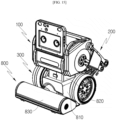
- FIG. 1 is a perspective view for describing a robot according to one embodiment of the present disclosure
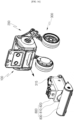
- FIG. 2 is an exploded perspective view of FIG. 1
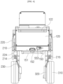
- FIG. 3 is a front view of the robot according to one embodiment of the present disclosure
- FIG. 4 is a rear view of the robot according to one embodiment of the present disclosure
- FIG. 5 is a side view of the robot according to one embodiment of the present disclosure
- FIG. 6 is a bottom view of the robot according to one embodiment of the present disclosure
- FIG. 7 is a view for describing a state in which an upper functional module has been removed from the robot according to one embodiment of the present disclosure.
- a robot 1 according to one embodiment of the present disclosure will be described as follows.
- the robot 1 according to the embodiment of the present disclosure is placed on a floor to move along a floor surface B. Therefore, the following description will be made by setting a vertical direction based on a state in which the robot 1 is placed on the floor.
- a "lowest portion" of each component described in the embodiment of the present disclosure may be a portion of each component that is located to be lowest when the robot 1 according to the embodiment of the present disclosure is used by being placed on the floor, or may be a portion closet to the floor.
- the robot 1 includes a robot body 100, a leg unit 200, and a wheel unit 300.
- the leg unit 200 is coupled to both side surfaces of the robot body 100
- the wheel unit 300 is coupled to the leg unit 200.
- the robot body 100 may form an exterior of the robot 1. Components constituting the robot 1 may be coupled to the robot body 100.
- leg unit 200 is coupled to each of frames 130 of both side surfaces of the robot body 100.
- a bumper 112 may be coupled to a front cover 110 provided on a front surface of the robot body 100.
- functional modules 700 and 800 may be detachably coupled to the robot body 100 according to one embodiment of the present disclosure.
- the functional modules 700 and 800 may include the upper functional module 700 coupled to an upper portion of the robot body 100 and the lower functional module 800 coupled to a space between a pair of wheels 310.
- the upper functional module 700 may be detachably coupled to an upper cover 140 disposed at an upper side of the robot body 100.
- the lower functional module 800 may be detachably coupled to a lower cover 150 disposed at a lower side of the robot body 100.
- the robot body 100 may be formed in a shape that has a horizontal width (or a diameter) larger than a vertical height.
- the robot body 100 may assist the robot 1 to have a stable structure and provide a structure that is advantageous in maintaining balance when the robot 1 moves (travels).
- Some components constituting the robot 1 may be accommodated inside the robot body 100.
- an internal space of the robot body 100 may accommodate one or more motors including a suspension motor MS, one or more sensors, and the battery 600.
- the robot body 100 includes a front cover 110.
- the front cover 110 constitutes a front exterior of the robot 1. That is, the front cover 110 may be disposed at the foremost portion of the robot 1 when the robot 1 travels forward.
- the front cover 110 of the robot body 100 may be formed in a flat shape.
- the front cover 110 may have a plate shape with a curved surface.
- the front cover 110 may have a plate shape bent at a predetermined angle.
- the front cover 110 may be provided with a window 111.
- the window 111 may be made of a material through which light may transmit.
- the window 111 may be made of a material through which infrared (IR), visible rays, or ultraviolet (UV) rays may transmit.
- IR infrared
- UV ultraviolet
- the front cover 110 includes an outer surface exposed to the outside of the robot 1 and an inner surface disposed on a back surface of the outer surface.
- the bumper 112 may be coupled to the outer surface of the front cover 110. That is, the bumper 112 may be disposed in front of the robot body 100.
- the bumper 112 may be provided at both end portions of the outer surface of the front cover 110, and a pair of bumpers 112 may be disposed in parallel in a vertical direction.
- the bumper 112 may be provided to move relatively with respect to the robot body 100.
- the bumper 112 may be coupled to the robot body 100 to reciprocate in a front-rear direction of the robot body 100.
- the bumper 112 may be coupled along a portion of a front edge of the front cover 110. Alternatively, the bumper 112 may be coupled along the entire edge of the front cover 110. With this configuration, when the robot 1 collides with another object or person, the bumper 112 can protect the robot body 100 and components accommodated inside the robot body 100 by absorbing an impact applied to the robot body 100.
- a first camera 531 may be disposed behind the inner surface of the front cover 110. Specifically, the first camera 531 may be disposed immediately behind the window 111. With this configuration, the first camera 531 may detect objects or people disposed in front of the robot 1.
- the front cover 110 may include an input unit through which a control command is input from a user, a display unit for visually conveying information about an operating state of the robot 1 to the user, etc.
- the front cover 110 may include a touch screen for visually displaying the operating state of the robot 1 and allowing the control command to be input from the user.
- the robot body 100 includes a rear cover 120.
- the rear cover 120 constitutes a rear exterior of the robot 1.
- the rear cover 120 may be formed in a flat plate shape.
- the rear cover 120 may have a plate shape with a curved surface.
- a manipulation unit 553 for adjusting power of the robot 1 may be disposed on the rear cover 120.
- the manipulation unit 553 may be manipulated by the user, and the robot 1 may be turned on or off by manipulating the manipulation unit 553.
- the manipulation unit 553 may be provided on the rear cover 120 to pivot in a left-right direction or provided to pivot in the vertical direction according to an embodiment.
- the robot 1 when the user pushes one side of the manipulation unit 553 and the manipulation unit 553 pivots to one side, the robot 1 may be turned on. In addition, when the user pushes the other side of the manipulation unit 553 and the manipulation unit 553 pivots to the other side, the robot 1 may be turned off.
- a rear bumper 122 may be coupled to an outer surface of the rear cover 120. That is, the rear bumper 122 may be disposed behind the robot body 100.
- the rear bumper 122 may be provided on the outer surface of the rear cover 120 and may be disposed in the horizontal direction. With this configuration, when the robot 1 collides with another object or person, the bumper 122 can protect the robot body 100 and the components accommodated inside the robot body 100 by absorbing an impact applied to the robot body 100.
- the robot body 100 includes a side frame 130.
- the side frame 130 constitutes the exterior of both side surfaces of the robot 1.
- the side frame 130 may be disposed on each of both side surfaces of the robot 1 and configured to face each other.
- the side frame 130 may be formed in a flat plate shape.
- at least a portion of the side frame 130 may be formed in a curved shape.
- the side frame 130 is coupled to the front cover 110 and the rear cover 120.
- the side frame 130 may connect the front cover 110 to the rear cover 120.
- the robot body 100 may have an internal space surrounded by the front cover 110, the rear cover 120, and the two side frames 130.
- the leg unit 200 may be disposed outside the side frame 130. Specifically, a first link 210 and a second link 220 may be rotatably coupled to the outside of the side frame 130.
- a support structure is disposed vertically under the robot body to support a load of the robot.
- the support structure is present vertically under the robot body, there is a limitation in that a space under the robot cannot be used.
- the robot 1 according to the embodiment of the present disclosure has the leg unit 200 coupled to the side frame 130.
- the suspension motor MS may be disposed inside the side frame 130.
- Link coupling holes 131 and 132 are formed in the side frame 130.
- the link coupling holes include the first link coupling hole 131 and the second link coupling hole 132.
- the first link coupling hole 131 is formed in a circular hole shape in the side frame 130. At least a portion of the first link 210 may be rotatably accommodated in the first link coupling hole 131. For example, one end portion of the first link 210 may be coupled to a shaft of the suspension motor MS through the first link coupling hole 131.
- the second link coupling hole 132 is formed in a circular hole shape in the side frame 130. At least a portion of the second link 220 may be rotatably accommodated in the second link coupling hole 132. For example, the shaft formed at one side of the second link 220 may be rotatably coupled by passing through the second link coupling hole 132.
- the first link coupling hole 131 may be formed to have a larger diameter than the second link coupling hole 132.
- the first link coupling hole 131 and the second link coupling hole 132 may be formed at a predetermined interval.
- the center of the first link coupling hole 131 in a circular hole shape and the center of the second link coupling hole 132 in a circular hole shape may be disposed at the predetermined interval.
- the first link coupling hole 131 and the second link coupling hole 132 may be disposed at a predetermined inclination with respect to the ground.
- the first link coupling hole 131 may be disposed at a lower side of the side frame 130
- the second link coupling hole 132 may be disposed at an upper rear side of the side frame 130.
- the side frame 130 in which the link coupling holes 131 and 132 are formed may function as a kind of link.
- a handle hole 133 may be formed in the side frame 130.
- the handle hole 133 may be formed at an upper front side of the side frame 130. With this configuration, the user may lift the robot body 100 upward by inserting his/her hand into the handle hole 133 and gripping the side frame 130.
- the upper cover 140 constitutes an upper exterior of the robot 1.
- the upper cover 140 is coupled to the front cover 110, the rear cover 120 and the two side frames 130. Therefore, the upper cover 140 may cover an upper side of the internal space surrounded by the front cover 110, the rear cover 120, and the two side frames 130.
- the upper cover 140 may be disposed to be inclined at a predetermined angle with respect to the ground.
- a front end portion of the upper cover 140 may be disposed closer to the ground than a rear end portion thereof is.
- the upper functional module 700 may be coupled to the upper cover 140.
- the upper functional module 700 may be detachably coupled to an upper side of the upper cover 140.
- a hook accommodation groove 141 may be formed to be hook-coupled to the upper functional module 700 in the upper cover 140.
- the upper functional module 700 may be coupled to the robot body 100 by only a user's simply operation of pushing the hook of the upper functional module 700 into the hook accommodation groove 141.
- the robot body 100 may supply power to the upper functional module 700.
- the upper cover 140 may include a terminal through which power may be supplied to the upper functional module 700.
- the robot body 100 may transmit and receive signals to the upper functional module 700.
- the upper cover 140 may include the terminal through which the signals may be transmitted and received to and from the upper functional module 700.
- the terminal through which power may be supplied to the upper functional module 700 and the terminal through which the signals may be transmitted and received to and from the upper functional module 700 may be disposed together on the upper cover 140.
- the upper cover 140 may include a pogo pin 142 including two power pins and four signal pins.
- At least one guide groove 143 may be formed in the upper cover 140. Alower surface of the upper functional module 700 may be coupled to the guide groove 143. With this configuration, the guide groove 143 may guide a coupling location of the upper functional module 700.
- the lower cover 150 forms a lower exterior of the robot 1.
- the lower cover 150 is coupled to the front cover 110, the rear cover 120, and the two side frames 130. Therefore, the lower cover 150 may cover a lower side of the internal space surrounded by the front cover 110, the rear cover 120, and the two side frames 130.
- the lower functional module 800 may be coupled to the lower cover 150.
- the lower functional module 800 may be detachably coupled to a lower side of the lower cover 150.
- the lower cover 150 may include a coupling bar 151 to be latch-coupled to the lower functional module 800.
- the coupling bar 151 may be formed in a cylindrical shape and disposed in the left-right direction of the robot 1.
- a pair of protrusions connected to the coupling bar 151 may be formed to protrude from the lower cover 150.
- the lower cover 150 may include a charging terminal 152.
- the charging terminal 152 may be disposed on a lower surface of the lower cover 150.
- the charging terminal 152 may be disposed at a location facing the charging terminal provided on a robot charging station (not shown).
- the charging terminal 152 may be electrically connected to a charging terminal provided on the robot charging station (not shown).
- the robot 1 may receive power from the robot charging station (not shown) through the charging terminal 152.
- the power supplied to the charging terminal 152 may be supplied to the battery 600.
- the support structure is disposed vertically under the robot body to support the load of the robot.
- the support structure is present vertically under the robot body, there is a limitation in that the space under the robot cannot be used.
- the robot 1 has the leg unit 200 disposed on both side surfaces of the robot body 100. Therefore, a module coupling space 153 to which the lower functional module 800 is coupled is formed at the lower side of the lower cover 150.
- the module coupling space 153 may be formed between the pair of leg units 200.
- the module coupling space 153 may be a space vertically under the coupling bar 151. That is, the module coupling space 153 may be a space having a predetermined width ⁇ S in the left-right direction.
- the lower functional module 800 may be coupled to a space between the lower portion of the robot body 100 and the pair of leg units 200, thereby minimizing a volume in a state in which the lower functional module 800 is coupled to the robot 1.
- the robot body 100 may further include an external case.
- the external case may constitute the overall exterior of the robot body 100.
- the external case may cover the exteriors of the front cover 110, the rear cover 120, the side frame 130, the upper cover 140, and the lower cover 150.
- the external case may be formed in an elliptical shape formed to extend in the left-right direction.
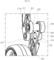
- FIG. 8 is a view for describing a leg unit in the robot according to one embodiment of the present disclosure
- FIG. 9 is a view for describing a connection relationship of the leg unit in the robot according to one embodiment of the present disclosure
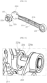
- FIG. 10 is a view for describing a second link in the robot according to one embodiment of the present disclosure
- FIG. 11 is a view for describing a structure for hiding an electric wire in the robot according to one embodiment of the present disclosure.
- leg unit 200 of the robot 1 according to one embodiment of the present disclosure will be described with reference to FIGS. 8 to 11 as follows.
- the leg unit 200 may be coupled to the robot body 100 to support the robot body 100.
- a pair of leg units 200 are provided and are each coupled to the side frame 130 of the robot body 100.
- at least a portion of the leg unit 200 is disposed closer to the ground than the robot body 100. Therefore, the robot body 100 may be supported by the pair of leg units 200. That is, gravity applied to the robot body 100 may be supported by the leg unit 200, and a height of the robot body 100 can be maintained.
- the leg unit 200 is coupled to only both side surfaces of the robot body 100. That is, the leg unit 200 is not coupled to the lower and rear surfaces of the robot body 100.
- a space 153 (module coupling space) is formed between the lower side of the lower cover 150 and the pair of leg units 200.
- a space in which a rectangular parallelepiped-shaped lower functional module 800 may be accommodated may be formed between the lower side of the lower cover 150 and the pair of leg units 200.
- the leg unit 200 includes the first link 210, the second link 220, and the third link 230.
- the first link 210 and the second link 220 are rotatably coupled to the side frame 130 and the third link 230, respectively. That is, the first link 210 and the second link 220 are link-coupled to the side frame 130 and the third link 230, respectively.
- the first link 210 is link-coupled to the side surface of the robot body 100.
- the first link 210 may be link-coupled to the side frame 130.
- the first link 210 is connected to the suspension motor MS.
- the first link 210 may be connected to the shaft of the suspension motor MS directly or through a gear. With this configuration, the first link 210 receives a driving force from the suspension motor MS.
- the first link 210 includes a first link body 211, a motor coupling portion 212, and a link coupling portion 213.
- the first link body 211 is formed in an extended frame shape, the motor coupling portion 212 is provided at one side in a longitudinal direction, and the link coupling portion 213 is provided at the other side in the longitudinal direction. In this case, the motor coupling portion 212 may be disposed farther from the ground than the link coupling portion 213.
- the first link body 211 may be formed in a shape that is bent at least once.
- the other side of the first link body 211 provided with the link coupling portion 213 may be disposed farther from the robot body 100 than the one side provided with the motor coupling portion 212.
- a distance between the pair of first link bodies 211 increases from the top to the bottom in the vertical direction.
- the first link 210 can stably support the robot body 100.
- a rib 211a may be formed on the first link body 211.
- the rib may be formed to protrude from the first link body 211 in the longitudinal direction.
- the rib 211a may be formed in an area in which the first link body 211 is bent. With this configuration, the rib 211a can increase durability by reinforcing the first link 210.
- the motor coupling portion 212 is formed to be connected to one end portion of the first link body 211.
- the motor coupling portion 212 is rotatably accommodated in the first link coupling hole 131 of the side frame 130.
- the motor coupling portion 212 may be formed in a disk shape or a circular panel shape.
- a maximum diameter of the motor coupling portion 212 may be equal to or smaller than a maximum diameter of the first link coupling hole 131. Therefore, the motor coupling portion 212 may be connected to the suspension motor MS through the first link coupling hole 131.
- the motor coupling portion 212 is connected to the suspension motor MS.
- the motor coupling portion 212 is fixedly coupled to the shaft of the suspension motor MS. With this configuration, when the suspension motor MS is driven, the motor coupling portion 212 may be rotated in conjunction with the rotation of the shaft of the suspension motor MS.
- the link coupling portion 213 is formed to be connected to the other end portion of the first link body 211.
- the link coupling portion 213 is rotatably coupled to the third link 230.
- the link coupling portion 213 is rotatably coupled to the third link 230 through a first link shaft 214.
- the link coupling portion 213 may be formed in a disk shape, and the first link shaft 214 may be coupled by passing through the center of the link coupling portion 213.
- the first link shaft 214 may be rotatably coupled by passing through the third link 230. With this configuration, the first link 210 and the third link 230 may be connected to rotate relatively.
- the first link shaft 214 is provided to connect the first link 210 to the third link 230.
- the first link shaft 214 may be coupled by passing through the link coupling portion 213 of the first link 210 and/or the third link 230.
- the first link shaft 214 may be rotatably coupled to the link coupling portion 213 and/or the third link 230.
- the first link shaft 214 may be an axis about which the third link 230 rotates.
- a gravity compensator 215 compensates for the robot body 100 that moves down vertically due to gravity. That is, the gravity compensator 215 provides a force for supporting the robot body 100.
- the gravity compensator 215 may be a torsion spring.
- the gravity compensator 215 may be wound to surround an outer circumferential surface of the first link shaft 214.
- one end portion of the gravity compensator 215 is coupled to the first link 210, and the other end portion of the gravity compensator 215 is coupled to the third link 230.
- the gravity compensator 215 applies a force in a direction in which an angle between the first link 210 and the third link 230 increases. For example, angles of both end portions of the gravity compensator 215 decrease in advance to apply a restoring force in a direction in which the angle between the first link 210 and the third link 230 increases. Therefore, even when the robot 1 is placed on the ground and gravity is applied to the robot body 100, the angle between the first link 210 and the third link 230 can be maintained within a predetermined angle range.
- the gravity compensator 215 prevents energy loss due to driving the suspension motor MS and maintains the height of the robot body 100 to a predetermined distance or more from the ground.
- the second link 220 is link-coupled to the side surface of the robot body 100.
- the second link 220 may be link-coupled to the side frame 130. That is, the second link 220 may be coupled to the side frame 130 to which the first link 210 is coupled together.
- the second link 220 includes a second link body 221, a frame coupling portion 222, and a link coupling portion 223.
- the frame coupling portion 222 may be disposed farther from the ground than the link coupling portion 223.
- the second link body 221 is formed in an extended frame shape, the frame coupling portion 222 is provided at one side in a longitudinal direction, and the link coupling portion 223 is provided at the other side in the longitudinal direction.
- the second link body 221 may be formed in a shape that is bent at least once.
- the other side of the second link body 221 provided with the link coupling portion 223 may be disposed farther from the robot body 100 than the one side provided with the frame coupling portion 222. Therefore, a distance between the pair of second link bodies 221 increases from the top to the bottom in the vertical direction. With this configuration, the second link 220 can stably support the robot body 100.
- the second link body 221 includes an inner surface facing the robot body 100 and an outer surface facing a direction away from the robot body 100.
- a rib 221a may be formed on the second link body 221.
- the rib 221a may be formed to protrude from the outer surface of the second link body 221 in the longitudinal direction.
- the rib 221a may be formed in an area in which the second link body 221 is bent. With this configuration, the rib 221a can increase durability by reinforcing the second link 220.
- An electric wire accommodation wall 221b may be formed on the second link body 221.
- a pair of electric wire accommodation walls 221b may be formed to protrude from the inner surface of the second link body 221 in the longitudinal direction.
- the pair of electric wire accommodation walls 221b may be formed in parallel at a predetermined interval.
- the internal space formed between the pair of electric wire accommodation walls 221b may communicate with an electric wire through hole 222c to be described below.
- the electric wire passing through the electric wire through hole 222c may be accommodated in the internal space formed between the electric wire accommodation walls 221b, thereby preventing the electric wire from being exposed to the outside.
- the second link 220 may be provided with an electric wire support pin 221c.
- the electric wire support pin 221c may pass through the pair of electric wire accommodation walls 221b.
- the electric wire support pin 221c may be disposed in a direction crossing the pair of electric wire accommodation walls 221b.
- the electric wire accommodation wall 221b may close an open area in the space surrounded by the second link body 221 and the electric wire accommodation walls 221b. Therefore, it is possible to prevent the electric wire from coming out of the space surrounded by the second link body 221 and the electric wire accommodation walls 221b.
- the frame coupling portion 222 is formed to be connected to one end portion of the second link body 221.
- the frame coupling portion 222 is rotatably coupled to the second link coupling hole 132 of the side frame 130.
- the frame coupling portion 222 may be provided with a coupling shaft 222a coupled by passing through the side frame 130.
- the coupling shaft 222a may be formed in a cylindrical shape.
- an outer diameter of the other end portion of the coupling shaft 222a may be larger than an outer diameter of one end portion of the coupling shaft 222a coupled to the side frame 130 in an axial direction (longitudinal direction).
- a hollow 222b may be formed in the coupling shaft 222a.
- the electric wire may pass through the hollow 222b.
- the electric wire through hole 222c may be formed in the coupling shaft 222a.
- the electric wire through hole 222c may be formed on an outer circumferential surface of the other end portion of the coupling shaft 222a in the axial direction.
- the coupling shaft 222a may be coupled to a rotational connection plate 222d.
- the rotational connection plate 222d may be formed in a disk shape, and a diameter of the rotational connection plate 222d may be formed to be smaller than a diameter of the other end portion of the coupling shaft 222a in the axial direction. Therefore, the rotational connection plate 222d may be coupled by being accommodated in the other end portion of the coupling shaft 222a in the axial direction.
- the rotational connection plate 222d may be formed integrally with the second link body 221. An outer end portion of the rotational connection plate 222d in a radial direction may be formed to be connected to the second link body 221. With this configuration, the rotational connection plate 222d may couple the second link body 221 to the coupling shaft 222a.
- the link coupling portion 223 is formed to be connected to the other end portion of the second link body 221.
- the link coupling portion 223 is rotatably coupled to the third link 230.
- the link coupling portion 223 is rotatably coupled to the third link 230 through a second link shaft 224.
- the link coupling portion 223 may be formed in a disk shape, and the second link shaft 224 may be coupled by passing through the center of the link coupling portion 223.
- the second link shaft 224 may be rotatably coupled by passing through the third link 230. With this configuration, the second link 220 and the third link 230 may be connected to rotate relatively.
- the second link shaft 224 is provided to connect the second link 220 to the third link 230.
- the second link shaft 224 may be coupled by passing through the link coupling portion 223 of the second link 220 and/or the third link 230.
- the second link shaft 224 may be rotatably coupled to the link coupling portion 223 and/or the third link 230.
- the second link shaft 224 may be an axis about which the third link 230 rotates.
- the third link 230 is link-coupled to the first link 210 and the second link 220 and coupled to the wheel unit 300.
- the third link 230 includes a third link body 231.
- the third link body 231 is formed in an extended frame shape, a third link coupling hole 232 and a fourth link coupling hole 233 are formed at one side thereof in the longitudinal direction, and a wheel coupling portion 234 is formed at the other side in the longitudinal direction.
- the third link body 231 may be formed in a shape that is bent at least once.
- a pair of third link bodies 231 have a distance between the other sides at which the wheel coupling portion 234 is formed, which is shorter than a distance between one sides at which the third link coupling hole 232 and the fourth link coupling hole 233 are formed.
- At least one rib 231a may be formed to protrude from the third link body 231 in the longitudinal direction.
- the rib 231a may be formed in a bent area of the third link body 231. With this configuration, the rib may reinforce the third link body 231.
- the third link coupling hole 232 is formed in the third link body 231. Specifically, the third link coupling hole 232 is formed at one side of the third link body 231 in the longitudinal direction.
- the first link shaft 214 may be rotatably coupled by passing through the third link coupling hole 232.
- the third link coupling hole 232 may be formed in a circular hole shape. With this configuration, the third link 230 may be rotatably connected to the first link 210 through the first link shaft 214.
- a hole into which the gravity compensator 215 is coupled may be formed in the third link body 231.
- the other end portion of the torsion spring may be coupled by being inserted into the hole.
- the fourth link coupling hole 233 is formed in the third link body 231. Specifically, the fourth link coupling hole 233 is formed at one side of the third link body 231 in the longitudinal direction.
- the second link shaft 224 may be rotatably coupled by passing through the fourth link coupling hole 233.
- the fourth link coupling hole 233 may be formed in a circular hole shape. With this configuration, the third link 230 may be rotatably connected to the second link 220 through the second link shaft 224.
- the fourth link coupling hole 233 may be disposed farther from the wheel coupling portion 234 than the third link coupling hole 232.
- the third link 230 is coupled to the wheel unit 300.
- a wheel housing 320 is coupled to an inner surface (surface facing the robot body 100) of the third link body 231, and the wheel 310 is rotatably coupled to an outer surface (back surface of the inner surface) of the third link body 231.
- the wheel coupling portion 234 is formed on the third link body 231. Specifically, the wheel coupling portion 234 is formed at the other side of the third link body 231 in the longitudinal direction.
- the wheel coupling portion 234 may be formed in a circular hole shape.
- the wheel motor MW may be accommodated in the wheel coupling portion 234.
- the wheel coupling portion 234 may be disposed vertically under the robot body 100.
- the wheel coupling portion 234 may be disposed vertically under the suspension motor MS.
- the suspension motor MS is relatively heavy among the components accommodated in the robot body 100. Therefore, the entire weight of the robot body 100 may be concentrated vertically under the suspension motor MS.
- the wheel 310 coupled to the wheel coupling portion 234 can maintain the balance of the robot body 100 by supporting a lower side of the center of gravity of the robot body 100.
- the wheel unit 300 may be rotatably coupled to the leg unit 200 and may roll along the ground.
- the wheel unit 300 includes the wheel 310 that is in contact with the ground and rolls along the ground, and the wheel housing 320 in which the wheel motor MW is accommodated.
- the wheel 310 is provided to have a predetermined radius and a predetermined width in the axial direction. As shown in FIG. 3 , when viewing the robot 1 from the front, the side frame 130 and the leg unit 200 may be disposed vertically above the wheel 310. In addition, as shown in FIG. 5 , when viewing the side surface of the robot 1, the suspension motor MS, the first link coupling hole 131, and the second link coupling hole 132 may be disposed vertically above the wheel 310.
- the suspension motor MS, the first link coupling hole 131, and the second link coupling hole 132 may be disposed vertically above the wheel 310.
- the wheel 310 includes a wheel frame 311 formed in a circular shape.
- the wheel frame 311 may be formed in a cylindrical shape with an open one side facing the shaft of the wheel motor MW. Therefore, a weight of the wheel frame 311 can be reduced.
- the overall rigidity of the wheel frame 311 can be reduced.
- the rib (not shown) for reinforcing rigidity may be formed on each of the inner and outer surfaces of the wheel frame 311.
- a wheel tire 312 is coupled to an outer circumferential surface of the wheel frame 311.
- the wheel tire 312 may be formed in an annular shape with a diameter of the wheel tire 312 fitted into the outer circumferential surface of the wheel frame 311.
- Grooves of a predetermined pattern may be recessed in the outer circumferential surface of the wheel tire 312 to increase a grip force of the wheel tire 312.
- the wheel tire 312 may be made of an elastic rubber material.
- the wheel housing 320 may have a cylindrical shape with an open one side in the axial direction so that the wheel motor MW is accommodated therein. In this case, a closed portion of the wheel housing 320 may be coupled to an inner surface of the third link 230. With this configuration, it is possible to prevent an external foreign substance from flowing into the wheel housing 320.
- the wheel housing 320 may be provided with a sensor for measuring a distance to the ground.
- the sensor may be a time of flight sensor (ToF sensor).
- a controller 500 may determine whether the wheel 310 is in contact with the ground.
- the wheel 310 is rotatably coupled to the leg unit 200. Specifically, the wheel 310 is rotatably coupled to an outer surface of the third link 230.
- the wheel motor MW may provide a driving force to the wheel 310.
- the wheel motor MW may generate a rotational force by receiving power from the battery 600.
- the wheel motor MW may be accommodated in the wheel housing 320.
- the wheel motor MW may pass through the wheel coupling portion 234 of the third link 230, and the shaft of the wheel motor MW may be coupled to the wheel frame 311 of the wheel 310. That is, the wheel motor MW may be an in-wheel motor.
- the wheel 310 may roll along the ground while rotating, and the robot 1 may move along the ground.
- FIGS. 12 and 13 are views for describing a change in location of a wheel according to the movement of the leg unit in the robot according to one embodiment of the present disclosure
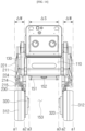
- FIG. 14 is a view for describing a relationship between the arrangement of the wheel and the arrangement for coupling with a lower functional module in the robot according to one embodiment of the present disclosure.
- the robot 1 may support the robot body 100 through the four-bar linkage structure and maintain the balance of the robot body 100.
- the leg unit 200 is provided on each of both side surfaces of the robot body 100.
- the first link 210 and the second link 220 are rotatably coupled to the side frames 130 provided at both sides of the robot body 100, and the first link 210 and the second link (220) is link-coupled to the third link 230. That is, the robot 1 supports the robot body 100 through the four-bar linkage composed of the side frame 130, the first link 210, the second link 220, and the third link 230.
- the robot body 100 when viewing the side surface of the robot body 100 as shown in FIGS. 12 and 13 , the robot body 100 may be disposed vertically above the wheel 310. With this configuration, the wheel 310 can stably support the load of the robot body 100.
- the motor coupling portion 212 may be disposed vertically above the wheel 310.
- the wheel 310 can stably support the motor coupling portion 212 to which the load of the robot body 100 is intensively transmitted and maintain the balance of the robot 1.
- the coupling bar 151 may be disposed vertically above the wheel 310.
- the entire load of the robot 1 may be concentrated vertically above the wheel 310, and the wheel 310 can stably support the robot 1.
- the gravity compensator 215 generates a restoring force in a direction of lifting the robot body 100. Therefore, even in a state in which the suspension motor MS is not driven, the pair of leg units 200 can maintain the state of lifting the robot body 100 to a predetermined height from the ground.
- the robot 1 can maintain the balance by lifting any one of the pair of wheels 310 to pass an obstacle or driving the suspension motor MS when the height of the robot body 100 is lowered for charging, etc.
- the link coupling portion 213 moves upward as the first link 210 rotates about the motor coupling portion 212.
- the third link 230 is moved by rotating the first link 210.
- the second link 220 is rotated by being pushed by the third link 230.
- one end portion of the third link 230 may be moved rearward, and the other end portion of the third link 230 may be moved upward.
- the robot 1 can stably maintain the balance.
- the robot 1 according to the present disclosure may pass obstacles of various heights using the four-bar linkage structure.
- a center C1 of the first link coupling hole 131 and a center C2 of the second link coupling hole 132 may be disposed at a predetermined first distance d1.
- a center C1 of the motor coupling portion 212 of the first link 210 and a center C3 of the link coupling part 213 of the first link 210 may be disposed at a predetermined second distance d2.
- a center C2 of the frame coupling portion 222 of the second link 220 and a center C4 of the link coupling portion 223 of the second link 220 may be disposed at a predetermined third distance d3.
- a center C3 of the third link coupling hole 232 of the third link 230 and a center C4 of the fourth link coupling hole 233 of the third link 230 may be disposed at a predetermined fourth distance d4.
- the center C3 of the third link coupling hole 232 of the third link 230 and a rotation center C5 of the wheel coupling portion 234 of the third link 230 may be disposed at a predetermined fifth distance d5.
- C5 can be defined as the rotation center of the wheel.
- the first distance d1, the second distance d2, the third distance d3, the fourth distance d4, and the fifth distance d5 may be disposed to have a predetermined length ratio.
- the first distance d1 may be 0.5 times or more and 0.6 times or less the fifth distance d5.
- the second distance d2 may be 0.95 times or more and 1.05 times or less the fifth distance d5.
- the third distance d3 may be 1.1 times or more and 1.2 times or less the fifth distance d5.
- the fourth distance d4 may be 0.2 times or more and 0.3 times or less the fifth distance d5.
- a movement distance of the wheel coupling portion 234 in the front-rear direction can be maintained within a predetermined deviation ⁇ D.
- the movement distance of the wheel coupling portion 234 in the front-rear direction can be maintained within 2% of the fifth distance d5.
- the center of gravity of the robot body 100 may be disposed vertically above the wheel 310. Therefore, the robot 1 can be prevented from shaking in the front-rear direction while moving and can maintain the balance.
- the balance can be maintained without changing locations of the wheels 310 in the front-rear direction.
- the robot body 100 is supported by the pair of leg units 200 and the pair of wheel units 300.
- the load of the robot body 100 may be transmitted to the wheel 310 through the leg units 200, and the wheel 310 may support the leg units 200 and the robot body 100.
- the pair of leg units 200 may be disposed symmetrically (line symmetrically).
- the link-coupled portions of the pair of leg units 200 may be disposed in parallel.
- the motor coupling portions 212 of the pair of first links 210 may be disposed in parallel.
- the link coupling portions 213 of the pair of first links 210 may be disposed in parallel.
- the frame coupling portions 222 of the pair of second links 220 may be disposed in parallel.
- the link coupling portions 223 of the pair of second links 220 may be disposed in parallel.
- the wheel coupling portions 234 of the pair of third links 230 may be disposed in parallel.
- the module coupling space 153 having a predetermined width ⁇ S is formed at the lower side of the robot body 100.
- the module coupling space 153 may be formed in parallel to the pair of leg units 200.
- the module coupling space 153 may be formed in parallel to the pair of wheels 310.
- At least one motor including the suspension motor MS and the battery 600 may be provided inside the robot body 100.
- the entire load of the robot body 100 in a state in which the motor and the battery 600 are accommodated may be applied to the leg units 200.
- the robot 1 since the robot 1 according to one embodiment of the present disclosure is provided with the leg unit 200 at both side surfaces of the robot body 100, the load of the robot body 100 is concentrated on the pair of side frames 130 and the pair of leg units 200.
- the side frame 130 and the leg units 200 may all be disposed vertically above the wheel unit 300.
- the side frame 130 and the leg units 200 may be disposed in a virtual space extending the wheel 310 in the vertical direction.
- both the side frames 130 and the leg units 200 may all be disposed between a virtual line al vertically extending the outer end portion of the wheel 310 in the axial direction and a virtual line a2 vertically extending the inner end portion of the wheel 310 in the axial direction.
- thicknesses (length of the robot 1 in the left-right direction) of the leg unit 200 and the side frame 130 are smaller than a thickness (length of the robot 1 in the left-right direction, ⁇ W) of the wheel 310.
- the entire load of the robot body 100 applied to the side frames 130 and the leg units 200 can be stably supported by the wheels 310 disposed thereunder in the direction of gravity.
- the balance of the robot body 100 can be stably maintained by concentrating the load of the robot body 100 vertically above the pair of wheels 310.
- leg unit 200 may be pressed vertically downward by the load of the robot body 100, and the application of the load of the robot 1 in the left-right direction can be prevented, thereby preventing the robot 1 from shaking in the left-right direction.
- FIG. 15 is a perspective view of a robot in a state in which the lower functional module is coupled to a robot body in the robot according to a first embodiment of the present disclosure
- FIG. 16 is a perspective view of the robot in a state before the lower functional module is coupled to the robot body in the robot according to the first embodiment of the present disclosure
- FIG. 17 is a perspective view of the lower functional module according to the first embodiment of the present disclosure
- FIG. 18 is a plan view of the lower functional module according to the first embodiment of the present disclosure
- FIG. 19 is a right side view of the lower functional module according to the first embodiment of the present disclosure
- FIG. 20 is a view showing a state before a coupling bar is coupled to a coupling hook in the robot according to the first embodiment of the present disclosure
- FIG. 21 is a view showing a state after the coupling bar is coupled to the coupling hook in FIG. 20 .
- the robot includes the lower functional module 800.
- the lower functional module 800 is a component coupled to the robot body 100 to provide various functions to the home robot.
- the lower functional module 800 is detachably coupled to the robot body 100.
- the robot may perform dry cleaning when the lower functional module 800 according to the first embodiment is coupled to the robot body 100, the robot may perform wet cleaning when the lower functional module 800 according to the second embodiment is coupled to the robot body 100, and the robot may transport another object when the lower functional module 800 according to the third embodiment is coupled to the robot body 100.
- the lower functional module 800 is coupled to the lower surface of the robot body 100.
- the coupling bar 151 and the charging terminal 152 to be coupled to the lower functional module 800 are disposed on the lower cover 150 of the robot body 100.
- the coupling bar 151 of the lower cover 150 is caught on a coupling hook 821 of the lower functional module 800, and thus the lower functional module 800 is physically coupled to the robot body 100.
- the charging terminal 152 of the lower cover 150 is coupled to a corresponding terminal 825 of the lower functional module 800, and thus the lower functional module 800 is electrically connected to the robot body 100.
- the lower functional module 800 When the lower functional module 800 is coupled to the robot body 100, the lower functional module 800 is disposed between the left leg unit and the right leg unit. That is, when the lower functional module 800 is coupled to the robot body 100, the lower functional module 800 is disposed between the left wheel 310 and the right wheel 310.
- the robot body 100 moves forward from the rear of the lower functional module 800 and approaches the lower functional module 800.
- the charging terminal 152 of the lower cover 150 of the robot body 100 and the corresponding terminal 825 of the lower functional module 800 are disposed to overlap vertically, the robot body 100 moves downward, and the charging terminal 152 is in contact with the corresponding terminal 825, and thus the robot body 100 and the lower functional module 800 are electrically connected, and the coupling hook 821 is caught on the coupling bar 151, and thus the robot body 100 is physically connected to the lower functional module 800.
- the lower functional module 800 is disposed between the left wheel 310 and the right wheel 310 when coupled to the robot body 100. Specifically, the lower functional module 800 is disposed in the module coupling space 153 formed between the pair of leg units. The lower functional module 800 may be disposed in the space between the lower portion of the robot body 100 and the pair of wheels 310, thereby minimizing the volume in the state in which the lower functional module 800 is coupled to the robot.
- a virtual vertical line extending upward from the rotation center C5 of the wheel is disposed between the coupling bar 151 and the charging terminal 152.
- the virtual vertical line extending upward from the rotation center C5 of the wheel is disposed between the coupling bar 151 and the charging terminal 152.
- the lower functional module 800 may be composed of a body 810 and a robot body fastening unit 820.
- the lower functional module body 810 forms the exterior of the lower functional module 800 and has a space in which components are stored.
- the lower functional module 800 includes a rear guide 811.
- the rear guide 811 is a component for guiding the robot body 100 to a location at which the lower functional module 800 is coupled.
- the rear guide 811 is formed to protrude rearward from a rear surface of the lower functional module body 810.
- the rear guide 811 may be coupled to a lower surface of the lower functional module body 810.
- the rear guide 811 protrudes rearward from the lower functional module body 810.
- the rear guide 811 guides the robot to the side surface of the lower functional module body 810.
- the left wheel 310 of the robot is in close contact with a left side surface of the rear guide 811, and the robot moves to the left.
- the right wheel 310 of the robot is in close contact with a right side surface of the rear guide 811, and the robot moves to the right. Therefore, the robot and the lower functional module 800 are aligned in line.
- the rear guide 811 has an outer end disposed in front of the center thereof. Therefore, an inclined surface facing the left front is formed at the left side of the center of the rear guide 811, and an inclined surface facing the right front is formed at the right side of the center of the rear guide 811.
- the robot when the robot is biased to one side and approaches the lower functional module 800, the robot moves laterally along the inclined surface, and the robot and the lower functional module 800 may be aligned in line.
- the rear guide 811 forms a curved surface that is convex rearward when viewed from the top.
- the rear guide 811 may be formed in a C shape with an open front. With this arrangement, when the one side wheel 310 is in contact with the rear guide 811, the rear guide 811 may more easily guide the wheel 310 to the left or right.
- the rear guide 811 has a front end disposed under a rear end thereof. That is, the rear end of the rear guide 811 is formed at a predetermined height or higher, and a height of the center of the rear guide 811 is formed to be higher than a height of the outer end of the rear guide 811.
- the robot when the robot is biased to one side and approaches the lower functional module 800, the robot may be effectively guided in one direction at the rear end of the rear guide 811, and the wheel 310 does not go up an upper portion of the rear guide.
- a front end of the rear guide 811 is disposed under the rear end of the rear guide 811, a contact area between the rear guide 811 and the inner surface of the wheel 310 can be reduced, thereby reducing a frictional force, and thus the robot to which the lower functional module 800 is coupled may move more easily.
- the lower functional module 800 includes a lateral guide 812.
- the lateral guide 812 is a component for guiding the robot body 100 to a location at which the lower functional module 800 is coupled.
- the lateral guide 812 is formed to protrude outward from one side surface of the lower functional module body 810.
- the lateral guide 812 may be coupled to the lower surface of the lower functional module body 810.
- the lateral guide 812 may be formed integrally with the rear guide 811.
- the lateral guide 812 may be extend forward from the front end of the rear guide 811.
- the lower functional module 800 includes a front stopper 813.
- the front stopper 813 is a component for preventing the robot body 100 from moving forward more than a specific location.
- the front stopper 813 is formed to protrude outward from the lower functional module body 810, and a rear surface thereof is disposed adjacent to the wheel 310 of the robot body 100.
- the left front stopper 813 is formed to protrude leftward from a left side surface of the lower functional module body 810, and the right front stopper 813 is formed to protrude rightward from a right side surface of the lower functional module body 810.
- a rear surface of the front stopper 813 has an upper end disposed in front of a lower end thereof.
- the front stopper 813 includes a front upward inclined surface.
- the rear surface of the front stopper 813 may extend in a circumferential direction of the wheel 310.
- the robot body 100 moves forward, the robot is caught on the front stopper 813 and may not move forward any more.
- the robot body 100 moves forward quickly, the robot may move up a predetermined distance along the rear surface of the front stopper 813 and then re-move down.
- the front stopper 813 is disposed to be spaced apart from the wheel 310 when the lower functional module 800 is coupled to the robot body 100. Therefore, since friction with the front stopper 813 does not occur when the wheel 310 rotates, the robot body 100 may be easily moved.
- the lower functional module 800 includes a guide light radiation unit 815.
- the guide light radiation unit 815 is a component for guiding the robot body 100 to approach the lower functional module 800 in a correct direction.
- the guide light radiation unit 815 is disposed in the lower functional module body 810 and radiates guidance light, which enables the robot body 100 to be recognized, rearward. Referring to FIG. 16 , the guide light irradiation unit 815 radiates guide light backward toward the robot body 100 (marked by dotted lines).
- the guide light radiation unit 815 may be disposed at a rear end of the lower functional module body 810.
- the robot body 100 includes a detection sensor (not shown) for detecting the guide light radiated from the guide light radiation unit 815.
- the robot body 100 may approach the lower functional module 800 along the guide light.
- the robot body fastening unit 820 is a component for coupling the lower functional module 800 to the robot body 100.
- the robot body fastening unit 820 is disposed at one side of the lower functional module body 810 and fixes the lower functional module body 810 to the robot body 100 when coupled. Specifically, the robot body fastening unit 820 is disposed on an upper surface of the lower functional module body 810. The robot body fastening unit 820 may be fixed to the lower cover 150 of the robot body 100.
- the robot body fastening unit 820 includes the coupling hook 821 and the corresponding terminal 825.
- the coupling hook 821 disposed in the lower functional module 800 is caught on the coupling bar 151 disposed on the lower cover 150 of the robot body 100, and thus the robot body fastening unit 820 couples the lower functional module 800 to the robot body 100.
- the coupling hook 821 is disposed in the lower functional module body 810. Specifically, a lower end of the coupling hook 821 is rotatably coupled to the lower functional module body 810.
- the coupling hook 821 is caught on one side of the robot body 100 when the lower functional module 800 is coupled to the robot body 100. Specifically, one end of the coupling hook 821 is fixed by being caught on the coupling bar 151.
- a locking protrusion caught on a hook link 822 is formed at the other end of the coupling hook 821.
- the robot body fastening unit 820 includes the hook link 822.
- the hook link 822 is a component for preventing the coupling hook 821 from being released when the coupling hook 821 is caught on the coupling bar 151.
- the hook link 822 is rotatably coupled to the lower functional module body 810.
- a locking protrusion caught on the locking protrusion of the coupling hook is formed at one end of the hook link 822. That is, the locking protrusion of the coupling hook 821 is caught on the locking protrusion of the hook link 822.
- the other end of the hook link 822 is disposed adjacent to a hook switch 823.
- the robot body fastening unit 820 includes the hook switch 823.
- the hook switch 823 is a component for releasing the catching between the coupling hook 821 and the coupling bar 151.
- the hook switch 823 is movably disposed in the lower functional module body 810. Specifically, the hook switch 823 is adjacent to the other end of the hook link 822.
- the hook link 822 may rotate clockwise, and the coupling hook 821 may rotate clockwise, and thus the robot body 100 may be separated from the lower functional module 800.
- the coupling bar 151 is disposed in the robot body 100. Specifically, the coupling bar 151 is disposed on the lower cover 150 of the robot body 100.
- the charging terminal 152 is disposed on the lower cover 150 of the robot body 100.
- a socket recessed downward is formed on the upper surface of the lower functional module body 810, and the corresponding terminal 825 is disposed on the socket.
- the robot body 100 and the lower functional module 800 may be electrically connected.
- the charging terminal 152 disposed on the lower cover 150 of the robot body 100 or the corresponding terminal 825 of the lower functional module 800 may be formed in the same shape as the pogo pin 142 disposed on the upper cover 140 of the robot body 100.
- the lower functional module 800 may perform dry cleaning.
- the lower functional module 800 includes a suction motor (not shown), a suction unit 831, and a dust bin 837.
- the suction motor is disposed in the lower functional module body 810 to generate a negative pressure.
- the suction motor may be disposed inside the lower functional module body 810.
- the suction unit 831 is disposed at an upstream of the suction motor to suction dust present in a cleaning area.
- the suction unit 831 may be disposed in front of the lower functional module body 810.
- the dust bin 837 is disposed at a downstream of the suction motor to collect dust.
- the dust bin 837 may be disposed behind the lower functional module body 810.
- the guide light radiation unit 815 may be disposed at one side of the dust bin 837.
- the lower functional module 800 may further include a brush 833.
- the brush 833 sweeps away a foreign substance present in the cleaning area for effective suction.
- the brush 833 may be disposed on the suction unit 831.
- the lower functional module 800 may further include a battery (not shown).
- the battery of the lower functional module drives a suction motor (not shown) or provides power for rotating the brush 833.
- the battery of the lower functional module 800 may be disposed inside the lower functional module body 810.
- the battery of the lower functional module 800 may be electrically connected to the battery of the robot body 100. Therefore, the battery of the lower functional module 800 may be charged using the battery of the robot body 100, and the battery of the robot body 100 may be charged using the battery of the lower functional module 800.
- FIG. 22 is a right side view of the lower functional module having a wet cleaning function according to a second embodiment of the present disclosure.
- the lower functional module 800 may perform wet cleaning.
- the lower functional module 800 includes a mop 841 and a water container 845.
- the mop 841 is disposed at one side of the lower functional module body 810 to mop the cleaning area.
- the mop 841 may be disposed on the lower surface of the lower functional module body 810.
- the mop 841 may be a spin mop that rotates about a rotational axis.
- the rotational axis of the mop 841 may be disposed perpendicular to the ground.
- the water container 845 is disposed in the lower functional module body 810 to store water and supply water to the mop 841.
- the water container 845 may be disposed behind the lower functional module body 810.
- the water container 845 may be disposed at a location of the dust bin 837 in the first embodiment.
- the lower functional module 800 may further include a mop motor (not shown).
- the mop motor transmits power for rotating the mop 841 to the mop 841.
- the mop motor may be disposed inside the lower functional module body 810.
- the lower functional module 800 may further include a battery (not shown).
- the battery of the lower functional module drives the mop motor or provides power for pumping water in the water container 845 to the mop 841.
- the battery of the lower functional module 800 may be disposed inside the lower functional module body 810.
- FIG. 23 is a right side view of the lower functional module having a transport function according to a third embodiment of the present disclosure.
- the lower functional module 800 may transport another object (object to be transported).
- the lower functional module 800 includes a gripper arm 853 and a gripper 851.
- the gripper arm 853 is movably coupled to the lower functional module body 810.
- the gripper arm 853 may be formed by rotatably coupling a plurality of arms. In this case, the gripper arm 853 may have a wide work radius by rotating the plurality of arms.
- the gripper 851 is disposed on an end portion of the arm to fix the object to be transported.
- the gripper 851 may pick up and lift a mobile phone, a large foreign substance, etc.
- the lower functional module 800 according to the third embodiment may transport the object to be transported to another location when the gripper 851 lifts the object to be transported.
Landscapes
- Engineering & Computer Science (AREA)
- Mechanical Engineering (AREA)
- Robotics (AREA)
- Chemical & Material Sciences (AREA)
- Combustion & Propulsion (AREA)
- Transportation (AREA)
- Manipulator (AREA)
- Electric Vacuum Cleaner (AREA)
Abstract
Description
- The present disclosure relates to a robot, and more specifically, to a robot capable of providing various services according to a user's command input.
- Recently, with the advancement of a robot technology, the use of robots is increasing not only in industrial fields but also at home.
- Home robots are robots that perform home tasks on behalf of people, such as helping with housework such as cleaning or controlling home appliances, or robots that act as a user's assistant or provide training to the user using artificial intelligence (AI), robots that replace companion animals, etc.
- However, conventional home robots have limitations in that they perform only any one of the above functions and may not perform various functions depending on the user's needs or circumstances.
- Meanwhile, there are not only robots that perform functions in a state of being fixed at a specific location but also movable mobile robots. In particular, in the case of robots used at home, the mobile robots that replace the user or move around the home while following the user are mainly used.
- Among the mobile robots, two-wheeled robots with two wheels have advantages of being easy to store because they occupy a small area of ground and being easily used in homes with a relatively limited space due to a small rotation radius when the robot changes a direction.
- However, the conventional two-wheeled robots have a limitation that a height of an obstacle at which the robots may pass is set in proportion to sizes of the wheels, and have a limitation that even when passing the obstacle, the robots may be not balanced due to an impact in a process of passing the obstacle, and thus the robot may fall over.
- In particular, when home robots perform a function of transporting drinks or food, an object to be transported may spill or fall on the floor when the robot shakes.
- As
Patent Document 1,US Patent No. 10010784 Patent Document 1 relates to a suspension system with one wheel. -
Patent Document 1 relates to a suspension device that has a four-bar linkage structure mounted in a vehicle with one wheel to restrict the wheel to only move up and down and absorbs an impact by arranging a damper on an end portion of the four-bar linkage. - However, since the deck is moved up by driving the damper in
Patent Document 1, there is a problem that a height at which the deck may move up is limited. - In addition, since the four-bar linkage in
Patent Document 1 is disposed at the side of the wheel, the wheel is exposed upward from the deck, and thus there is a problem that all areas of the deck cannot be used. - Meanwhile, the conventional robots need to be provided with functional modules to perform various additional functions according to the user's needs. In this case, the functional modules may be coupled to any one location in all directions of the robot.
- However, in
Patent Document 1, the functional modules cannot be disposed under the robot and should be coupled to an upper portion or any one of the left, right, front, or rear portion thereof. In this case, when the functional modules are disposed on the upper portion of the robot, the center of gravity of the entire robot assembly becomes higher than before, resulting in a problem that traveling is unstable. Alternatively, when the functional modules are disposed on the left, right, front, or rear portion of the robot, the entire area of the robot assembly increases, resulting in a problem that the robot may not travel in narrow places. - As Patent Document 2,
Japanese Patent No. 5978423 - The crawler traveling search robot according to Patent Document 2 has an arm driving mechanism capable of controlling an inclined angle of a vehicle body by rotating an arm in a width direction of the vehicle body forward or backward to pressing a step. Therefore, the crawler traveling search robot according to Patent Document 2 may pass a step of about 15 cm or more.
- However, to mount a functional module on a crawler traveling search robot according to Patent Document 2, the functional module should be mounted at a front, rear, or upper end of the vehicle body. However, in this case, there may be a problem that the arm driving mechanism gets caught on the functional module when the arm driving mechanism rotates.
-
- (Patent Document 1)
US Patent No. 10010784 - (Patent Document 2)
Japanese Patent No. 5978423 - The present disclosure has been made in efforts to solve the problems of the related art. Specifically, the present disclosure is directed to providing a robot that may be moved by at least two wheels and selectively coupled to modules capable of performing various types of functions to perform various functions according to situations.
- In addition, the present disclosure is directed to providing a robot capable of minimizing a space of a coupled assembly even when modules for performing functions are coupled.
- In addition, the present disclosure is directed to providing a robot in which a coupled assembly may stably travel even when modules for performing functions are coupled.
- To achieve the objects, a robot according to the present disclosure includes a robot body in which a motor and a battery are accommodated, a leg unit coupled to each of both side surfaces of the robot body, a wheel unit rotatably coupled to the leg unit to roll along a ground, and a lower functional module detachably coupled to the robot body. The lower functional module includes a lower functional module body forming an exterior and having a space therein, and a robot body fastening unit disposed at one side of the lower functional module body to fix the lower functional module body to the robot body when coupled.
- The lower functional module may include a rear guide protruding rearward from a rear surface of the lower functional module body. When viewed from the top, an outer end of the rear guide may be disposed in front of a center thereof. Alternatively, when viewed from the top, the rear guide may form a curved surface that is convex rearward. When viewed from one side, the rear guide may have a front end disposed under a rear end thereof.
- The lower functional module may include a front stopper formed to protrude outward from the lower functional module body and having a rear surface disposed adjacent to a wheel of the robot body. In this case, the rear surface of the front stopper may have an upper end disposed in front of a lower end thereof. Alternatively, the front stopper may be disposed to be spaced apart from the wheel when the lower functional module is coupled to the robot body.
- The lower functional module may include a guide light radiation unit configured to radiate guide light, which enables the robot body to be recognized, rearward.
- The robot body fastening unit may include a coupling hook disposed above the lower functional module body and caught on one side of the robot body when the lower functional module is coupled to the robot body. In this case, the robot body fastening unit may further include a hook link which has one end adjacent to the coupling hook and in which the other end of the coupling hook is caught on the one end when the one end of the coupling hook is coupled to the robot body, and a hook switch adjacent to the other end of the hook link and releasing the catching the coupling hook when pressing the other end of the hook link.
- The lower functional module may perform dry cleaning by including a suction motor disposed in the lower functional module body to generate a negative pressure, a suction unit disposed at an upstream of the suction motor to suction dust present in a cleaning area, and a dust bin disposed at a downstream of the suction motor to collect the dust.
- The lower functional module may perform wet cleaning by including a mop disposed at one side of the lower functional module body to mop the cleaning area, and a water container disposed in the lower functional module body to store water and supply the water to the mop.
- The lower functional module may transport an object to be transported by including a gripper arm movably coupled to the lower functional module body, and a gripper disposed on an end portion of the arm to fix the object to be transported.
- To achieve the objects, a robot according to the present disclosure includes a robot body in which a motor and a battery are accommodated, a leg unit coupled to each of both side surfaces of the robot body, a wheel unit rotatably coupled to the leg unit to roll along a ground, and a lower functional module detachably coupled to the robot body and disposed between a left wheel and a right wheel when coupled to the robot body.
- The robot body may include a lower cover forming a lower exterior of the robot, a coupling bar disposed on the lower cover and coupled to the lower functional module, and a charging terminal disposed on the lower cover and electrically connected to the lower functional module, and a virtual vertical line extending upward from a rotation center of the wheel may be disposed between the coupling bar and the charging terminal.
- The lower functional module includes a lower functional module body forming an exterior and having a space therein, and a robot body fastening unit disposed at one side of the lower functional module body to fix the lower functional module body to the robot body when coupled.
- Detailed matters of other embodiments are included in a detailed description and accompanying drawings.
- As described above, according to the robot of the present disclosure, there are the following effects.
- First, according to the robot of the present disclosure, the lower functional module may include the robot body fastening unit for fixing the lower functional module body and the lower functional module body to the robot body so that the lower functional module may be detachably coupled to the robot body. Therefore, the robot can perform operations in various modes by selectively coupling various types of lower functional modules to the robot body.
- Second, according to the robot of the present disclosure, the lower functional module may be coupled to the space between the lower portion of the robot body and the pair of leg units, thereby minimizing the space of the entire robot to which the lower functional module is coupled.
- Third, since the location of the center of gravity of the entire robot coupled becomes lower when the lower functional module is coupled to the robot body, the robot can stably travel.
- The effects of the present disclosure are not limited to the above-described effects, and other effects that are not described will be able to be clearly understood by those skilled in the art from the above detailed description.
-
-
FIG. 1 is a perspective view for describing a robot according to one embodiment of the present disclosure. -
FIG. 2 is an exploded perspective view of the robot according to one embodiment of the present disclosure. -
FIG. 3 is a front view of the robot according to one embodiment of the present disclosure. -
FIG. 4 is a rear view of the robot according to one embodiment of the present disclosure. -
FIG. 5 is a side view of the robot according to one embodiment of the present disclosure. -
FIG. 6 is a bottom view of the robot according to one embodiment of the present disclosure. -
FIG. 7 is a view for describing a state in which an upper functional module has been removed from the robot according to one embodiment of the present disclosure. -
FIG. 8 is a view for describing a leg unit in the robot according to one embodiment of the present disclosure. -
FIG. 9 is a view for describing a connection relationship of the leg unit in the robot according to one embodiment of the present disclosure. -
FIG. 10 is a view for describing a second link in the robot according to one embodiment of the present disclosure. -
FIG. 11 is a view for describing a structure for hiding an electric wire in the robot according to one embodiment of the present disclosure. -
FIGS. 12 and13 are views for describing a change in location of a wheel according to the movement of the leg unit in the robot according to one embodiment of the present disclosure. -
FIG. 14 is a view for describing a relationship between the arrangement of the wheel and the arrangement for coupling with a lower functional module in the robot according to one embodiment of the present disclosure. -
FIG. 15 is a perspective view of a robot in a state in which the lower functional module is coupled to a robot body in the robot according to a first embodiment of the present disclosure. -
FIG. 16 is a perspective view of the robot in a state before the lower functional module is coupled to the robot body in the robot according to the first embodiment of the present disclosure. -
FIG. 17 is a perspective view of the lower functional module according to the first embodiment of the present disclosure. -
FIG. 18 is a plan view of the lower functional module according to the first embodiment of the present disclosure. -
FIG. 19 is a right side view of the lower functional module according to the first embodiment of the present disclosure. -
FIG. 20 is a view showing a state before a coupling bar is coupled to a coupling hook in the robot according to the first embodiment of the present disclosure. -
FIG. 21 is a view showing a state after the coupling bar is coupled to the coupling hook inFIG. 20 . -
FIG. 22 is a right side view of the lower functional module having a wet cleaning function according to a second embodiment of the present disclosure. -
FIG. 23 is a right side view of the lower functional module having a transport function according to a third embodiment of the present disclosure. - Hereinafter, exemplary embodiments of the present disclosure will be described in detail with reference to the accompanying drawings.
- Since the present disclosure may have various changes and various embodiments, specific embodiments are shown in the accompanying drawings and specifically described in the detail descriptions. This is not intended to limit the present disclosure to specific embodiments and should be construed to include all modifications, equivalents, and substitutes included in the spirit and technical scope of the present disclosure.
-
FIG. 1 is a perspective view for describing a robot according to one embodiment of the present disclosure,FIG. 2 is an exploded perspective view ofFIG. 1 ,FIG. 3 is a front view of the robot according to one embodiment of the present disclosure,FIG. 4 is a rear view of the robot according to one embodiment of the present disclosure,FIG. 5 is a side view of the robot according to one embodiment of the present disclosure,FIG. 6 is a bottom view of the robot according to one embodiment of the present disclosure, andFIG. 7 is a view for describing a state in which an upper functional module has been removed from the robot according to one embodiment of the present disclosure. - Referring
FIGS. 1 to 7 , arobot 1 according to one embodiment of the present disclosure will be described as follows. - The
robot 1 according to the embodiment of the present disclosure is placed on a floor to move along a floor surface B. Therefore, the following description will be made by setting a vertical direction based on a state in which therobot 1 is placed on the floor. - In addition, the following description will be made by setting a side at which a mapping camera to be described below is disposed with respect to a battery 600 as a front. In addition, the following description will be made by setting a direction opposite to the front as a rear with respect to the battery 600.
- A "lowest portion" of each component described in the embodiment of the present disclosure may be a portion of each component that is located to be lowest when the
robot 1 according to the embodiment of the present disclosure is used by being placed on the floor, or may be a portion closet to the floor. - The
robot 1 according to the embodiment of the present disclosure includes arobot body 100, aleg unit 200, and awheel unit 300. In this case, theleg unit 200 is coupled to both side surfaces of therobot body 100, and thewheel unit 300 is coupled to theleg unit 200. - The
robot body 100 may form an exterior of therobot 1. Components constituting therobot 1 may be coupled to therobot body 100. - For example, the
leg unit 200 is coupled to each offrames 130 of both side surfaces of therobot body 100. In addition, abumper 112 may be coupled to afront cover 110 provided on a front surface of therobot body 100. - In particular,
functional modules robot body 100 according to one embodiment of the present disclosure. Here, thefunctional modules functional module 700 coupled to an upper portion of therobot body 100 and the lowerfunctional module 800 coupled to a space between a pair ofwheels 310. - Therefore, the upper
functional module 700 may be detachably coupled to anupper cover 140 disposed at an upper side of therobot body 100. The lowerfunctional module 800 may be detachably coupled to alower cover 150 disposed at a lower side of therobot body 100. - With this configuration, it is possible to perform various functions by coupling the
functional modules robot body 100. In addition, a new function may be added to the function in use by replacing thefunctional modules functional modules - In the embodiment of the present disclosure, the
robot body 100 may be formed in a shape that has a horizontal width (or a diameter) larger than a vertical height. Therobot body 100 may assist therobot 1 to have a stable structure and provide a structure that is advantageous in maintaining balance when therobot 1 moves (travels). - Some components constituting the
robot 1 may be accommodated inside therobot body 100. For example, an internal space of therobot body 100 may accommodate one or more motors including a suspension motor MS, one or more sensors, and the battery 600. - The
robot body 100 includes afront cover 110. Thefront cover 110 constitutes a front exterior of therobot 1. That is, thefront cover 110 may be disposed at the foremost portion of therobot 1 when therobot 1 travels forward. - For example, the
front cover 110 of therobot body 100 may be formed in a flat shape. As another example, thefront cover 110 may have a plate shape with a curved surface. As still another example, thefront cover 110 may have a plate shape bent at a predetermined angle. - The
front cover 110 may be provided with awindow 111. Thewindow 111 may be made of a material through which light may transmit. For example, thewindow 111 may be made of a material through which infrared (IR), visible rays, or ultraviolet (UV) rays may transmit. - The
front cover 110 includes an outer surface exposed to the outside of therobot 1 and an inner surface disposed on a back surface of the outer surface. - The
bumper 112 may be coupled to the outer surface of thefront cover 110. That is, thebumper 112 may be disposed in front of therobot body 100. For example, thebumper 112 may be provided at both end portions of the outer surface of thefront cover 110, and a pair ofbumpers 112 may be disposed in parallel in a vertical direction. - The
bumper 112 may be provided to move relatively with respect to therobot body 100. For example, thebumper 112 may be coupled to therobot body 100 to reciprocate in a front-rear direction of therobot body 100. - The
bumper 112 may be coupled along a portion of a front edge of thefront cover 110. Alternatively, thebumper 112 may be coupled along the entire edge of thefront cover 110. With this configuration, when therobot 1 collides with another object or person, thebumper 112 can protect therobot body 100 and components accommodated inside therobot body 100 by absorbing an impact applied to therobot body 100. - A first camera 531 may be disposed behind the inner surface of the
front cover 110. Specifically, the first camera 531 may be disposed immediately behind thewindow 111. With this configuration, the first camera 531 may detect objects or people disposed in front of therobot 1. - Meanwhile, although not shown, the
front cover 110 may include an input unit through which a control command is input from a user, a display unit for visually conveying information about an operating state of therobot 1 to the user, etc. For example, thefront cover 110 may include a touch screen for visually displaying the operating state of therobot 1 and allowing the control command to be input from the user. - The
robot body 100 includes arear cover 120. - The
rear cover 120 constitutes a rear exterior of therobot 1. For example, therear cover 120 may be formed in a flat plate shape. As another example, therear cover 120 may have a plate shape with a curved surface. - A
manipulation unit 553 for adjusting power of therobot 1 may be disposed on therear cover 120. - The
manipulation unit 553 may be manipulated by the user, and therobot 1 may be turned on or off by manipulating themanipulation unit 553. - The
manipulation unit 553 may be provided on therear cover 120 to pivot in a left-right direction or provided to pivot in the vertical direction according to an embodiment. - For example, when the user pushes one side of the
manipulation unit 553 and themanipulation unit 553 pivots to one side, therobot 1 may be turned on. In addition, when the user pushes the other side of themanipulation unit 553 and themanipulation unit 553 pivots to the other side, therobot 1 may be turned off. - A
rear bumper 122 may be coupled to an outer surface of therear cover 120. That is, therear bumper 122 may be disposed behind therobot body 100. For example, therear bumper 122 may be provided on the outer surface of therear cover 120 and may be disposed in the horizontal direction. With this configuration, when therobot 1 collides with another object or person, thebumper 122 can protect therobot body 100 and the components accommodated inside therobot body 100 by absorbing an impact applied to therobot body 100. - The
robot body 100 includes aside frame 130. - The
side frame 130 constitutes the exterior of both side surfaces of therobot 1. For example, theside frame 130 may be disposed on each of both side surfaces of therobot 1 and configured to face each other. For example, theside frame 130 may be formed in a flat plate shape. As another example, at least a portion of theside frame 130 may be formed in a curved shape. - The
side frame 130 is coupled to thefront cover 110 and therear cover 120. Theside frame 130 may connect thefront cover 110 to therear cover 120. With this configuration, therobot body 100 may have an internal space surrounded by thefront cover 110, therear cover 120, and the two side frames 130. - The
leg unit 200 may be disposed outside theside frame 130. Specifically, afirst link 210 and asecond link 220 may be rotatably coupled to the outside of theside frame 130. - Generally, in a two-wheeled robot, a support structure is disposed vertically under the robot body to support a load of the robot. However, when the support structure is present vertically under the robot body, there is a limitation in that a space under the robot cannot be used.
- To solve this, the
robot 1 according to the embodiment of the present disclosure has theleg unit 200 coupled to theside frame 130. - The suspension motor MS may be disposed inside the
side frame 130. - Link coupling holes 131 and 132 are formed in the
side frame 130. The link coupling holes include the firstlink coupling hole 131 and the secondlink coupling hole 132. - The first
link coupling hole 131 is formed in a circular hole shape in theside frame 130. At least a portion of thefirst link 210 may be rotatably accommodated in the firstlink coupling hole 131. For example, one end portion of thefirst link 210 may be coupled to a shaft of the suspension motor MS through the firstlink coupling hole 131. - The second
link coupling hole 132 is formed in a circular hole shape in theside frame 130. At least a portion of thesecond link 220 may be rotatably accommodated in the secondlink coupling hole 132. For example, the shaft formed at one side of thesecond link 220 may be rotatably coupled by passing through the secondlink coupling hole 132. - Meanwhile, the first
link coupling hole 131 may be formed to have a larger diameter than the secondlink coupling hole 132. - The first
link coupling hole 131 and the secondlink coupling hole 132 may be formed at a predetermined interval. For example, the center of the firstlink coupling hole 131 in a circular hole shape and the center of the secondlink coupling hole 132 in a circular hole shape may be disposed at the predetermined interval. - The first
link coupling hole 131 and the secondlink coupling hole 132 may be disposed at a predetermined inclination with respect to the ground. For example, in a state in which therobot 1 is placed on the ground, the firstlink coupling hole 131 may be disposed at a lower side of theside frame 130, and the secondlink coupling hole 132 may be disposed at an upper rear side of theside frame 130. - With this configuration, the
side frame 130 in which the link coupling holes 131 and 132 are formed may function as a kind of link. - Meanwhile, according to an embodiment, a
handle hole 133 may be formed in theside frame 130. For example, thehandle hole 133 may be formed at an upper front side of theside frame 130. With this configuration, the user may lift therobot body 100 upward by inserting his/her hand into thehandle hole 133 and gripping theside frame 130. - The
upper cover 140 constitutes an upper exterior of therobot 1. Theupper cover 140 is coupled to thefront cover 110, therear cover 120 and the two side frames 130. Therefore, theupper cover 140 may cover an upper side of the internal space surrounded by thefront cover 110, therear cover 120, and the two side frames 130. - In a state in which the
robot 1 is placed on the ground, theupper cover 140 may be disposed to be inclined at a predetermined angle with respect to the ground. For example, a front end portion of theupper cover 140 may be disposed closer to the ground than a rear end portion thereof is. - The upper
functional module 700 may be coupled to theupper cover 140. The upperfunctional module 700 may be detachably coupled to an upper side of theupper cover 140. For example, ahook accommodation groove 141 may be formed to be hook-coupled to the upperfunctional module 700 in theupper cover 140. With this configuration, the upperfunctional module 700 may be coupled to therobot body 100 by only a user's simply operation of pushing the hook of the upperfunctional module 700 into thehook accommodation groove 141. - The
robot body 100 may supply power to the upperfunctional module 700. Specifically, theupper cover 140 may include a terminal through which power may be supplied to the upperfunctional module 700. - In addition, the
robot body 100 may transmit and receive signals to the upperfunctional module 700. Specifically, theupper cover 140 may include the terminal through which the signals may be transmitted and received to and from the upperfunctional module 700. - Meanwhile, in the embodiment of the present disclosure, the terminal through which power may be supplied to the upper
functional module 700 and the terminal through which the signals may be transmitted and received to and from the upperfunctional module 700 may be disposed together on theupper cover 140. For example, theupper cover 140 may include apogo pin 142 including two power pins and four signal pins. - At least one
guide groove 143 may be formed in theupper cover 140. Alower surface of the upperfunctional module 700 may be coupled to theguide groove 143. With this configuration, theguide groove 143 may guide a coupling location of the upperfunctional module 700. - The
lower cover 150 forms a lower exterior of therobot 1. Thelower cover 150 is coupled to thefront cover 110, therear cover 120, and the two side frames 130. Therefore, thelower cover 150 may cover a lower side of the internal space surrounded by thefront cover 110, therear cover 120, and the two side frames 130. - The lower
functional module 800 may be coupled to thelower cover 150. The lowerfunctional module 800 may be detachably coupled to a lower side of thelower cover 150. Specifically, thelower cover 150 may include acoupling bar 151 to be latch-coupled to the lowerfunctional module 800. - The
coupling bar 151 may be formed in a cylindrical shape and disposed in the left-right direction of therobot 1. In addition, a pair of protrusions connected to thecoupling bar 151 may be formed to protrude from thelower cover 150. - The
lower cover 150 may include a chargingterminal 152. The chargingterminal 152 may be disposed on a lower surface of thelower cover 150. - In this case, the charging
terminal 152 may be disposed at a location facing the charging terminal provided on a robot charging station (not shown). The chargingterminal 152 may be electrically connected to a charging terminal provided on the robot charging station (not shown). Therobot 1 may receive power from the robot charging station (not shown) through the chargingterminal 152. In addition, the power supplied to the chargingterminal 152 may be supplied to the battery 600. - Meanwhile, in general, in the two-wheeled robot, the support structure is disposed vertically under the robot body to support the load of the robot. However, when the support structure is present vertically under the robot body, there is a limitation in that the space under the robot cannot be used.
- To solve this, the
robot 1 according to one embodiment of the present disclosure has theleg unit 200 disposed on both side surfaces of therobot body 100. Therefore, amodule coupling space 153 to which the lowerfunctional module 800 is coupled is formed at the lower side of thelower cover 150. - The
module coupling space 153 may be formed between the pair ofleg units 200. For example, themodule coupling space 153 may be a space vertically under thecoupling bar 151. That is, themodule coupling space 153 may be a space having a predetermined width ΔS in the left-right direction. - With this configuration, according to the
robot 1 according to the embodiment of the present disclosure, the lowerfunctional module 800 may be coupled to a space between the lower portion of therobot body 100 and the pair ofleg units 200, thereby minimizing a volume in a state in which the lowerfunctional module 800 is coupled to therobot 1. - Meanwhile, although not shown, according to an embodiment, the
robot body 100 may further include an external case. The external case may constitute the overall exterior of therobot body 100. The external case may cover the exteriors of thefront cover 110, therear cover 120, theside frame 130, theupper cover 140, and thelower cover 150. For example, the external case may be formed in an elliptical shape formed to extend in the left-right direction. -
FIG. 8 is a view for describing a leg unit in the robot according to one embodiment of the present disclosure,FIG. 9 is a view for describing a connection relationship of the leg unit in the robot according to one embodiment of the present disclosure,FIG. 10 is a view for describing a second link in the robot according to one embodiment of the present disclosure, andFIG. 11 is a view for describing a structure for hiding an electric wire in the robot according to one embodiment of the present disclosure. - The
leg unit 200 of therobot 1 according to one embodiment of the present disclosure will be described with reference toFIGS. 8 to 11 as follows. - The
leg unit 200 may be coupled to therobot body 100 to support therobot body 100. For example, a pair ofleg units 200 are provided and are each coupled to theside frame 130 of therobot body 100. In this case, at least a portion of theleg unit 200 is disposed closer to the ground than therobot body 100. Therefore, therobot body 100 may be supported by the pair ofleg units 200. That is, gravity applied to therobot body 100 may be supported by theleg unit 200, and a height of therobot body 100 can be maintained. - In the
robot 1 according to one embodiment of the present disclosure, theleg unit 200 is coupled to only both side surfaces of therobot body 100. That is, theleg unit 200 is not coupled to the lower and rear surfaces of therobot body 100. - Therefore, as shown in
FIG. 14 , a space 153 (module coupling space) is formed between the lower side of thelower cover 150 and the pair ofleg units 200. For example, a space in which a rectangular parallelepiped-shaped lowerfunctional module 800 may be accommodated may be formed between the lower side of thelower cover 150 and the pair ofleg units 200. - The
leg unit 200 includes thefirst link 210, thesecond link 220, and thethird link 230. In this case, thefirst link 210 and thesecond link 220 are rotatably coupled to theside frame 130 and thethird link 230, respectively. That is, thefirst link 210 and thesecond link 220 are link-coupled to theside frame 130 and thethird link 230, respectively. - The
first link 210 is link-coupled to the side surface of therobot body 100. For example, thefirst link 210 may be link-coupled to theside frame 130. - The
first link 210 is connected to the suspension motor MS. For example, thefirst link 210 may be connected to the shaft of the suspension motor MS directly or through a gear. With this configuration, thefirst link 210 receives a driving force from the suspension motor MS. - The
first link 210 includes afirst link body 211, amotor coupling portion 212, and alink coupling portion 213. - The
first link body 211 is formed in an extended frame shape, themotor coupling portion 212 is provided at one side in a longitudinal direction, and thelink coupling portion 213 is provided at the other side in the longitudinal direction. In this case, themotor coupling portion 212 may be disposed farther from the ground than thelink coupling portion 213. - The
first link body 211 may be formed in a shape that is bent at least once. For example, the other side of thefirst link body 211 provided with thelink coupling portion 213 may be disposed farther from therobot body 100 than the one side provided with themotor coupling portion 212. - Therefore, a distance between the pair of
first link bodies 211 increases from the top to the bottom in the vertical direction. With this configuration, thefirst link 210 can stably support therobot body 100. - A
rib 211a may be formed on thefirst link body 211. For example, the rib may be formed to protrude from thefirst link body 211 in the longitudinal direction. In this case, therib 211a may be formed in an area in which thefirst link body 211 is bent. With this configuration, therib 211a can increase durability by reinforcing thefirst link 210. - The
motor coupling portion 212 is formed to be connected to one end portion of thefirst link body 211. - The
motor coupling portion 212 is rotatably accommodated in the firstlink coupling hole 131 of theside frame 130. For example, themotor coupling portion 212 may be formed in a disk shape or a circular panel shape. In this case, a maximum diameter of themotor coupling portion 212 may be equal to or smaller than a maximum diameter of the firstlink coupling hole 131. Therefore, themotor coupling portion 212 may be connected to the suspension motor MS through the firstlink coupling hole 131. - The
motor coupling portion 212 is connected to the suspension motor MS. For example, themotor coupling portion 212 is fixedly coupled to the shaft of the suspension motor MS. With this configuration, when the suspension motor MS is driven, themotor coupling portion 212 may be rotated in conjunction with the rotation of the shaft of the suspension motor MS. - The
link coupling portion 213 is formed to be connected to the other end portion of thefirst link body 211. - The
link coupling portion 213 is rotatably coupled to thethird link 230. Specifically, thelink coupling portion 213 is rotatably coupled to thethird link 230 through afirst link shaft 214. For example, thelink coupling portion 213 may be formed in a disk shape, and thefirst link shaft 214 may be coupled by passing through the center of thelink coupling portion 213. In addition, thefirst link shaft 214 may be rotatably coupled by passing through thethird link 230. With this configuration, thefirst link 210 and thethird link 230 may be connected to rotate relatively. - The
first link shaft 214 is provided to connect thefirst link 210 to thethird link 230. For example, thefirst link shaft 214 may be coupled by passing through thelink coupling portion 213 of thefirst link 210 and/or thethird link 230. In this case, thefirst link shaft 214 may be rotatably coupled to thelink coupling portion 213 and/or thethird link 230. With this configuration, thefirst link shaft 214 may be an axis about which thethird link 230 rotates. - A
gravity compensator 215 compensates for therobot body 100 that moves down vertically due to gravity. That is, thegravity compensator 215 provides a force for supporting therobot body 100. - For example, the
gravity compensator 215 may be a torsion spring. Thegravity compensator 215 may be wound to surround an outer circumferential surface of thefirst link shaft 214. In addition, one end portion of thegravity compensator 215 is coupled to thefirst link 210, and the other end portion of thegravity compensator 215 is coupled to thethird link 230. - The
gravity compensator 215 applies a force in a direction in which an angle between thefirst link 210 and thethird link 230 increases. For example, angles of both end portions of thegravity compensator 215 decrease in advance to apply a restoring force in a direction in which the angle between thefirst link 210 and thethird link 230 increases. Therefore, even when therobot 1 is placed on the ground and gravity is applied to therobot body 100, the angle between thefirst link 210 and thethird link 230 can be maintained within a predetermined angle range. - With this configuration, it is possible to prevent the
robot body 100 from moving down toward the ground even when the suspension motor MS is not driven. Therefore, thegravity compensator 215 prevents energy loss due to driving the suspension motor MS and maintains the height of therobot body 100 to a predetermined distance or more from the ground. - The
second link 220 is link-coupled to the side surface of therobot body 100. For example, thesecond link 220 may be link-coupled to theside frame 130. That is, thesecond link 220 may be coupled to theside frame 130 to which thefirst link 210 is coupled together. - The
second link 220 includes asecond link body 221, aframe coupling portion 222, and alink coupling portion 223. In this case, theframe coupling portion 222 may be disposed farther from the ground than thelink coupling portion 223. - The
second link body 221 is formed in an extended frame shape, theframe coupling portion 222 is provided at one side in a longitudinal direction, and thelink coupling portion 223 is provided at the other side in the longitudinal direction. - The
second link body 221 may be formed in a shape that is bent at least once. For example, the other side of thesecond link body 221 provided with thelink coupling portion 223 may be disposed farther from therobot body 100 than the one side provided with theframe coupling portion 222. Therefore, a distance between the pair ofsecond link bodies 221 increases from the top to the bottom in the vertical direction. With this configuration, thesecond link 220 can stably support therobot body 100. - The
second link body 221 includes an inner surface facing therobot body 100 and an outer surface facing a direction away from therobot body 100. - A
rib 221a may be formed on thesecond link body 221. For example, therib 221a may be formed to protrude from the outer surface of thesecond link body 221 in the longitudinal direction. In this case, therib 221a may be formed in an area in which thesecond link body 221 is bent. With this configuration, therib 221a can increase durability by reinforcing thesecond link 220. - An electric
wire accommodation wall 221b may be formed on thesecond link body 221. For example, a pair of electricwire accommodation walls 221b may be formed to protrude from the inner surface of thesecond link body 221 in the longitudinal direction. In this case, the pair of electricwire accommodation walls 221b may be formed in parallel at a predetermined interval. With this configuration, the electric wire may be accommodated in the space surrounded by thesecond link body 221 and the electricwire accommodation walls 221b. Therefore, it is possible to prevent the electric wire from being exposed to the outside. - Meanwhile, the internal space formed between the pair of electric
wire accommodation walls 221b may communicate with an electric wire throughhole 222c to be described below. With this configuration, the electric wire passing through the electric wire throughhole 222c may be accommodated in the internal space formed between the electricwire accommodation walls 221b, thereby preventing the electric wire from being exposed to the outside. - In addition, the
second link 220 may be provided with an electricwire support pin 221c. The electricwire support pin 221c may pass through the pair of electricwire accommodation walls 221b. The electricwire support pin 221c may be disposed in a direction crossing the pair of electricwire accommodation walls 221b. With this configuration, the electricwire accommodation wall 221b may close an open area in the space surrounded by thesecond link body 221 and the electricwire accommodation walls 221b. Therefore, it is possible to prevent the electric wire from coming out of the space surrounded by thesecond link body 221 and the electricwire accommodation walls 221b. - The
frame coupling portion 222 is formed to be connected to one end portion of thesecond link body 221. - The
frame coupling portion 222 is rotatably coupled to the secondlink coupling hole 132 of theside frame 130. For example, theframe coupling portion 222 may be provided with acoupling shaft 222a coupled by passing through theside frame 130. - The
coupling shaft 222a may be formed in a cylindrical shape. For example, an outer diameter of the other end portion of thecoupling shaft 222a may be larger than an outer diameter of one end portion of thecoupling shaft 222a coupled to theside frame 130 in an axial direction (longitudinal direction). - A hollow 222b may be formed in the
coupling shaft 222a. The electric wire may pass through the hollow 222b. With this configuration, it is possible to prevent the electric wire through which power is supplied from the battery 600 to a wheel motor MW from being exposed to the outside. - In addition, the electric wire through
hole 222c may be formed in thecoupling shaft 222a. The electric wire throughhole 222c may be formed on an outer circumferential surface of the other end portion of thecoupling shaft 222a in the axial direction. With this configuration, in therobot body 100, the electric wire passing through the hollow 222b may pass through the electric wire throughhole 222c and may be accommodated in thesecond link body 221. - The
coupling shaft 222a may be coupled to arotational connection plate 222d. For example, therotational connection plate 222d may be formed in a disk shape, and a diameter of therotational connection plate 222d may be formed to be smaller than a diameter of the other end portion of thecoupling shaft 222a in the axial direction. Therefore, therotational connection plate 222d may be coupled by being accommodated in the other end portion of thecoupling shaft 222a in the axial direction. - The
rotational connection plate 222d may be formed integrally with thesecond link body 221. An outer end portion of therotational connection plate 222d in a radial direction may be formed to be connected to thesecond link body 221. With this configuration, therotational connection plate 222d may couple thesecond link body 221 to thecoupling shaft 222a. - The
link coupling portion 223 is formed to be connected to the other end portion of thesecond link body 221. - The
link coupling portion 223 is rotatably coupled to thethird link 230. Specifically, thelink coupling portion 223 is rotatably coupled to thethird link 230 through asecond link shaft 224. For example, thelink coupling portion 223 may be formed in a disk shape, and thesecond link shaft 224 may be coupled by passing through the center of thelink coupling portion 223. In addition, thesecond link shaft 224 may be rotatably coupled by passing through thethird link 230. With this configuration, thesecond link 220 and thethird link 230 may be connected to rotate relatively. - The
second link shaft 224 is provided to connect thesecond link 220 to thethird link 230. For example, thesecond link shaft 224 may be coupled by passing through thelink coupling portion 223 of thesecond link 220 and/or thethird link 230. In this case, thesecond link shaft 224 may be rotatably coupled to thelink coupling portion 223 and/or thethird link 230. With this configuration, thesecond link shaft 224 may be an axis about which thethird link 230 rotates. - The
third link 230 is link-coupled to thefirst link 210 and thesecond link 220 and coupled to thewheel unit 300. - The
third link 230 includes athird link body 231. Thethird link body 231 is formed in an extended frame shape, a thirdlink coupling hole 232 and a fourthlink coupling hole 233 are formed at one side thereof in the longitudinal direction, and awheel coupling portion 234 is formed at the other side in the longitudinal direction. - The
third link body 231 may be formed in a shape that is bent at least once. For example, a pair ofthird link bodies 231 have a distance between the other sides at which thewheel coupling portion 234 is formed, which is shorter than a distance between one sides at which the thirdlink coupling hole 232 and the fourthlink coupling hole 233 are formed. - At least one
rib 231a may be formed to protrude from thethird link body 231 in the longitudinal direction. Therib 231a may be formed in a bent area of thethird link body 231. With this configuration, the rib may reinforce thethird link body 231. - The third
link coupling hole 232 is formed in thethird link body 231. Specifically, the thirdlink coupling hole 232 is formed at one side of thethird link body 231 in the longitudinal direction. Thefirst link shaft 214 may be rotatably coupled by passing through the thirdlink coupling hole 232. For example, the thirdlink coupling hole 232 may be formed in a circular hole shape. With this configuration, thethird link 230 may be rotatably connected to thefirst link 210 through thefirst link shaft 214. - A hole into which the
gravity compensator 215 is coupled may be formed in thethird link body 231. For example, the other end portion of the torsion spring may be coupled by being inserted into the hole. - The fourth
link coupling hole 233 is formed in thethird link body 231. Specifically, the fourthlink coupling hole 233 is formed at one side of thethird link body 231 in the longitudinal direction. Thesecond link shaft 224 may be rotatably coupled by passing through the fourthlink coupling hole 233. For example, the fourthlink coupling hole 233 may be formed in a circular hole shape. With this configuration, thethird link 230 may be rotatably connected to thesecond link 220 through thesecond link shaft 224. - The fourth
link coupling hole 233 may be disposed farther from thewheel coupling portion 234 than the thirdlink coupling hole 232. - The
third link 230 is coupled to thewheel unit 300. In this case, awheel housing 320 is coupled to an inner surface (surface facing the robot body 100) of thethird link body 231, and thewheel 310 is rotatably coupled to an outer surface (back surface of the inner surface) of thethird link body 231. - Meanwhile, the
wheel coupling portion 234 is formed on thethird link body 231. Specifically, thewheel coupling portion 234 is formed at the other side of thethird link body 231 in the longitudinal direction. - For example, the
wheel coupling portion 234 may be formed in a circular hole shape. The wheel motor MW may be accommodated in thewheel coupling portion 234. - Meanwhile, in a state in which the
robot 1 stands on the ground, thewheel coupling portion 234 may be disposed vertically under therobot body 100. For example, in the state in which therobot 1 stands on the ground, thewheel coupling portion 234 may be disposed vertically under the suspension motor MS. - The suspension motor MS is relatively heavy among the components accommodated in the
robot body 100. Therefore, the entire weight of therobot body 100 may be concentrated vertically under the suspension motor MS. - With this configuration, the
wheel 310 coupled to thewheel coupling portion 234 can maintain the balance of therobot body 100 by supporting a lower side of the center of gravity of therobot body 100. - Referring to
FIGS. 1 to 7 , thewheel unit 300 may be rotatably coupled to theleg unit 200 and may roll along the ground. - The
wheel unit 300 includes thewheel 310 that is in contact with the ground and rolls along the ground, and thewheel housing 320 in which the wheel motor MW is accommodated. - The
wheel 310 is provided to have a predetermined radius and a predetermined width in the axial direction. As shown inFIG. 3 , when viewing therobot 1 from the front, theside frame 130 and theleg unit 200 may be disposed vertically above thewheel 310. In addition, as shown inFIG. 5 , when viewing the side surface of therobot 1, the suspension motor MS, the firstlink coupling hole 131, and the secondlink coupling hole 132 may be disposed vertically above thewheel 310. - In addition, referring to
FIG. 2 , the suspension motor MS, the firstlink coupling hole 131, and the secondlink coupling hole 132 may be disposed vertically above thewheel 310. - The
wheel 310 includes awheel frame 311 formed in a circular shape. Thewheel frame 311 may be formed in a cylindrical shape with an open one side facing the shaft of the wheel motor MW. Therefore, a weight of thewheel frame 311 can be reduced. - However, when the
wheel frame 311 is formed in a cylindrical shape, the overall rigidity of thewheel frame 311 can be reduced. In consideration of such a point, the rib (not shown) for reinforcing rigidity may be formed on each of the inner and outer surfaces of thewheel frame 311. - A
wheel tire 312 is coupled to an outer circumferential surface of thewheel frame 311. Thewheel tire 312 may be formed in an annular shape with a diameter of thewheel tire 312 fitted into the outer circumferential surface of thewheel frame 311. - Grooves of a predetermined pattern may be recessed in the outer circumferential surface of the
wheel tire 312 to increase a grip force of thewheel tire 312. - In one embodiment, the
wheel tire 312 may be made of an elastic rubber material. - The
wheel housing 320 may have a cylindrical shape with an open one side in the axial direction so that the wheel motor MW is accommodated therein. In this case, a closed portion of thewheel housing 320 may be coupled to an inner surface of thethird link 230. With this configuration, it is possible to prevent an external foreign substance from flowing into thewheel housing 320. - Meanwhile, the
wheel housing 320 may be provided with a sensor for measuring a distance to the ground. For example, the sensor may be a time of flight sensor (ToF sensor). With this configuration, a controller 500 may determine whether thewheel 310 is in contact with the ground. - The
wheel 310 is rotatably coupled to theleg unit 200. Specifically, thewheel 310 is rotatably coupled to an outer surface of thethird link 230. - The wheel motor MW may provide a driving force to the
wheel 310. The wheel motor MW may generate a rotational force by receiving power from the battery 600. - The wheel motor MW may be accommodated in the
wheel housing 320. In addition, the wheel motor MW may pass through thewheel coupling portion 234 of thethird link 230, and the shaft of the wheel motor MW may be coupled to thewheel frame 311 of thewheel 310. That is, the wheel motor MW may be an in-wheel motor. - With this configuration, when the wheel motor MW is driven, the
wheel 310 may roll along the ground while rotating, and therobot 1 may move along the ground. -
FIGS. 12 and13 are views for describing a change in location of a wheel according to the movement of the leg unit in the robot according to one embodiment of the present disclosure, andFIG. 14 is a view for describing a relationship between the arrangement of the wheel and the arrangement for coupling with a lower functional module in the robot according to one embodiment of the present disclosure. - Referring
FIGS. 12 to 14 , the balance of therobot 1 according to one embodiment of the present disclosure will be described as follows. - The
robot 1 according to the embodiment of the present disclosure may support therobot body 100 through the four-bar linkage structure and maintain the balance of therobot body 100. - The balance of the
robot 1 in the front-rear direction according to one embodiment of the present disclosure will be described with reference toFIGS. 12 and13 as follows. - The
leg unit 200 is provided on each of both side surfaces of therobot body 100. Specifically, thefirst link 210 and thesecond link 220 are rotatably coupled to the side frames 130 provided at both sides of therobot body 100, and thefirst link 210 and the second link (220) is link-coupled to thethird link 230. That is, therobot 1 supports therobot body 100 through the four-bar linkage composed of theside frame 130, thefirst link 210, thesecond link 220, and thethird link 230. - In this case, when viewing the side surface of the
robot body 100 as shown inFIGS. 12 and13 , therobot body 100 may be disposed vertically above thewheel 310. With this configuration, thewheel 310 can stably support the load of therobot body 100. - In particular, the
motor coupling portion 212 may be disposed vertically above thewheel 310. With this configuration, thewheel 310 can stably support themotor coupling portion 212 to which the load of therobot body 100 is intensively transmitted and maintain the balance of therobot 1. - Meanwhile, when viewing the side surface of the
robot body 100 as shown inFIGS. 12 and13 , thecoupling bar 151 may be disposed vertically above thewheel 310. With this configuration, even in a state in which the lowerfunctional module 800 is coupled to therobot body 100, the entire load of therobot 1 may be concentrated vertically above thewheel 310, and thewheel 310 can stably support therobot 1. - Meanwhile, in the embodiment of the present disclosure, the
gravity compensator 215 generates a restoring force in a direction of lifting therobot body 100. Therefore, even in a state in which the suspension motor MS is not driven, the pair ofleg units 200 can maintain the state of lifting therobot body 100 to a predetermined height from the ground. - Meanwhile, the
robot 1 according to the embodiment of the present disclosure can maintain the balance by lifting any one of the pair ofwheels 310 to pass an obstacle or driving the suspension motor MS when the height of therobot body 100 is lowered for charging, etc. - When the suspension motor MS is driven, the
link coupling portion 213 moves upward as thefirst link 210 rotates about themotor coupling portion 212. In addition, thethird link 230 is moved by rotating thefirst link 210. In addition, thesecond link 220 is rotated by being pushed by thethird link 230. As a result, one end portion of thethird link 230 may be moved rearward, and the other end portion of thethird link 230 may be moved upward. - With this configuration, even when the
wheel 310 moves upward and downward, a movement range of thewheel 310 in the front-rear direction may be limited. Therefore, therobot 1 can stably maintain the balance. - Therefore, the
robot 1 according to the present disclosure may pass obstacles of various heights using the four-bar linkage structure. - In the
robot 1 according to the embodiment of the present disclosure, a center C1 of the firstlink coupling hole 131 and a center C2 of the secondlink coupling hole 132 may be disposed at a predetermined first distance d1. In addition, a center C1 of themotor coupling portion 212 of thefirst link 210 and a center C3 of thelink coupling part 213 of thefirst link 210 may be disposed at a predetermined second distance d2. In addition, a center C2 of theframe coupling portion 222 of thesecond link 220 and a center C4 of thelink coupling portion 223 of thesecond link 220 may be disposed at a predetermined third distance d3. In addition, a center C3 of the thirdlink coupling hole 232 of thethird link 230 and a center C4 of the fourthlink coupling hole 233 of thethird link 230 may be disposed at a predetermined fourth distance d4. In addition, the center C3 of the thirdlink coupling hole 232 of thethird link 230 and a rotation center C5 of thewheel coupling portion 234 of thethird link 230 may be disposed at a predetermined fifth distance d5. - Meanwhile, C5 can be defined as the rotation center of the wheel.
- In this case, the first distance d1, the second distance d2, the third distance d3, the fourth distance d4, and the fifth distance d5 may be disposed to have a predetermined length ratio. For example, the first distance d1 may be 0.5 times or more and 0.6 times or less the fifth distance d5. The second distance d2 may be 0.95 times or more and 1.05 times or less the fifth distance d5. The third distance d3 may be 1.1 times or more and 1.2 times or less the fifth distance d5. The fourth distance d4 may be 0.2 times or more and 0.3 times or less the fifth distance d5.
- With this configuration, even when the
third link 230 is moved by driving the motion motor MS, a movement distance of thewheel coupling portion 234 in the front-rear direction can be maintained within a predetermined deviation ΔD. For example, even when thethird link 230 is moved, the movement distance of thewheel coupling portion 234 in the front-rear direction can be maintained within 2% of the fifth distance d5. - Therefore, while the
robot 1 is moving, the center of gravity of therobot body 100 may be disposed vertically above thewheel 310. Therefore, therobot 1 can be prevented from shaking in the front-rear direction while moving and can maintain the balance. - In addition, according to the
robot 1 according to the present disclosure, even when thewheels 310 move upward while therobot 1 passes an obstacle, the balance can be maintained without changing locations of thewheels 310 in the front-rear direction. - The balance of the
robot 1 in a left-right direction according to the embodiment of the present disclosure will be described with reference toFIG. 14 as follows. - As shown in
FIG. 14 , therobot body 100 is supported by the pair ofleg units 200 and the pair ofwheel units 300. - The load of the
robot body 100 may be transmitted to thewheel 310 through theleg units 200, and thewheel 310 may support theleg units 200 and therobot body 100. - In this case, the pair of
leg units 200 may be disposed symmetrically (line symmetrically). In particular, the link-coupled portions of the pair ofleg units 200 may be disposed in parallel. - Specifically, the
motor coupling portions 212 of the pair offirst links 210 may be disposed in parallel. Thelink coupling portions 213 of the pair offirst links 210 may be disposed in parallel. Theframe coupling portions 222 of the pair ofsecond links 220 may be disposed in parallel. Thelink coupling portions 223 of the pair ofsecond links 220 may be disposed in parallel. Thewheel coupling portions 234 of the pair ofthird links 230 may be disposed in parallel. - With this configuration, the
module coupling space 153 having a predetermined width ΔS is formed at the lower side of therobot body 100. Themodule coupling space 153 may be formed in parallel to the pair ofleg units 200. In addition, themodule coupling space 153 may be formed in parallel to the pair ofwheels 310. - At least one motor including the suspension motor MS and the battery 600 may be provided inside the
robot body 100. In addition, when therobot 1 is placed on the ground, the entire load of therobot body 100 in a state in which the motor and the battery 600 are accommodated may be applied to theleg units 200. - In particular, since the
robot 1 according to one embodiment of the present disclosure is provided with theleg unit 200 at both side surfaces of therobot body 100, the load of therobot body 100 is concentrated on the pair of side frames 130 and the pair ofleg units 200. - In this case, as shown in
FIG. 14 , based on when viewing the front surface of therobot 1 from the front of therobot 1, theside frame 130 and theleg units 200 may all be disposed vertically above thewheel unit 300. - For example, when viewing the front surface of the
robot 1 as shown inFIG. 18 , theside frame 130 and theleg units 200 may be disposed in a virtual space extending thewheel 310 in the vertical direction. - That is, as shown in
FIG. 14 , both the side frames 130 and theleg units 200 may all be disposed between a virtual line al vertically extending the outer end portion of thewheel 310 in the axial direction and a virtual line a2 vertically extending the inner end portion of thewheel 310 in the axial direction. - In addition, thicknesses (length of the
robot 1 in the left-right direction) of theleg unit 200 and theside frame 130 are smaller than a thickness (length of therobot 1 in the left-right direction, ΔW) of thewheel 310. - With this configuration, the entire load of the
robot body 100 applied to the side frames 130 and theleg units 200 can be stably supported by thewheels 310 disposed thereunder in the direction of gravity. - Therefore, according to the
robot 1 according to the embodiment of the present disclosure, the balance of therobot body 100 can be stably maintained by concentrating the load of therobot body 100 vertically above the pair ofwheels 310. - In addition, the
leg unit 200 may be pressed vertically downward by the load of therobot body 100, and the application of the load of therobot 1 in the left-right direction can be prevented, thereby preventing therobot 1 from shaking in the left-right direction. -
FIG. 15 is a perspective view of a robot in a state in which the lower functional module is coupled to a robot body in the robot according to a first embodiment of the present disclosure,FIG. 16 is a perspective view of the robot in a state before the lower functional module is coupled to the robot body in the robot according to the first embodiment of the present disclosure,FIG. 17 is a perspective view of the lower functional module according to the first embodiment of the present disclosure,FIG. 18 is a plan view of the lower functional module according to the first embodiment of the present disclosure,FIG. 19 is a right side view of the lower functional module according to the first embodiment of the present disclosure,FIG. 20 is a view showing a state before a coupling bar is coupled to a coupling hook in the robot according to the first embodiment of the present disclosure, andFIG. 21 is a view showing a state after the coupling bar is coupled to the coupling hook inFIG. 20 . - Referring to
FIG. 15 , the robot includes the lowerfunctional module 800. The lowerfunctional module 800 is a component coupled to therobot body 100 to provide various functions to the home robot. - The lower
functional module 800 is detachably coupled to therobot body 100. For example, the robot may perform dry cleaning when the lowerfunctional module 800 according to the first embodiment is coupled to therobot body 100, the robot may perform wet cleaning when the lowerfunctional module 800 according to the second embodiment is coupled to therobot body 100, and the robot may transport another object when the lowerfunctional module 800 according to the third embodiment is coupled to therobot body 100. - The lower
functional module 800 is coupled to the lower surface of therobot body 100. Thecoupling bar 151 and the chargingterminal 152 to be coupled to the lowerfunctional module 800 are disposed on thelower cover 150 of therobot body 100. - The
coupling bar 151 of thelower cover 150 is caught on acoupling hook 821 of the lowerfunctional module 800, and thus the lowerfunctional module 800 is physically coupled to therobot body 100. - The charging
terminal 152 of thelower cover 150 is coupled to acorresponding terminal 825 of the lowerfunctional module 800, and thus the lowerfunctional module 800 is electrically connected to therobot body 100. - When the lower
functional module 800 is coupled to therobot body 100, the lowerfunctional module 800 is disposed between the left leg unit and the right leg unit. That is, when the lowerfunctional module 800 is coupled to therobot body 100, the lowerfunctional module 800 is disposed between theleft wheel 310 and theright wheel 310. - The
robot body 100 moves forward from the rear of the lowerfunctional module 800 and approaches the lowerfunctional module 800. When the chargingterminal 152 of thelower cover 150 of therobot body 100 and thecorresponding terminal 825 of the lowerfunctional module 800 are disposed to overlap vertically, therobot body 100 moves downward, and the chargingterminal 152 is in contact with the correspondingterminal 825, and thus therobot body 100 and the lowerfunctional module 800 are electrically connected, and thecoupling hook 821 is caught on thecoupling bar 151, and thus therobot body 100 is physically connected to the lowerfunctional module 800. - The lower
functional module 800 is disposed between theleft wheel 310 and theright wheel 310 when coupled to therobot body 100. Specifically, the lowerfunctional module 800 is disposed in themodule coupling space 153 formed between the pair of leg units. The lowerfunctional module 800 may be disposed in the space between the lower portion of therobot body 100 and the pair ofwheels 310, thereby minimizing the volume in the state in which the lowerfunctional module 800 is coupled to the robot. - A virtual vertical line extending upward from the rotation center C5 of the wheel is disposed between the
coupling bar 151 and the chargingterminal 152. Referring toFIG. 13 , when viewed from the left, the virtual vertical line extending upward from the rotation center C5 of the wheel is disposed between thecoupling bar 151 and the chargingterminal 152. When the lowerfunctional module 800 is coupled to therobot body 100, the lowerfunctional module 800 faces a great area on the ground, and thus no behavior for maintaining the robot's attitude is required. Therefore, the rotation center C5 of the wheel is always disposed between thecoupling bar 151 and the chargingterminal 152, and the robot may travel more stably. - The lower
functional module 800 may be composed of abody 810 and a robotbody fastening unit 820. - The lower
functional module body 810 forms the exterior of the lowerfunctional module 800 and has a space in which components are stored. - Other components may be stored inside the lower
functional module body 810. - Referring to
FIGS. 17 to 19 , the lowerfunctional module 800 includes arear guide 811. Therear guide 811 is a component for guiding therobot body 100 to a location at which the lowerfunctional module 800 is coupled. - The
rear guide 811 is formed to protrude rearward from a rear surface of the lowerfunctional module body 810. - The
rear guide 811 may be coupled to a lower surface of the lowerfunctional module body 810. Therear guide 811 protrudes rearward from the lowerfunctional module body 810. - The
rear guide 811 guides the robot to the side surface of the lowerfunctional module body 810. For example, when the robot is biased to the right and approaches the lowerfunctional module 800, theleft wheel 310 of the robot is in close contact with a left side surface of therear guide 811, and the robot moves to the left. Conversely, when the robot is biased to the left and approaches the lowerfunctional module 800, theright wheel 310 of the robot is in close contact with a right side surface of therear guide 811, and the robot moves to the right. Therefore, the robot and the lowerfunctional module 800 are aligned in line. - The
rear guide 811 has an outer end disposed in front of the center thereof. Therefore, an inclined surface facing the left front is formed at the left side of the center of therear guide 811, and an inclined surface facing the right front is formed at the right side of the center of therear guide 811. In this case, as described above, when the robot is biased to one side and approaches the lowerfunctional module 800, the robot moves laterally along the inclined surface, and the robot and the lowerfunctional module 800 may be aligned in line. - The
rear guide 811 forms a curved surface that is convex rearward when viewed from the top. Specifically, therear guide 811 may be formed in a C shape with an open front. With this arrangement, when the oneside wheel 310 is in contact with therear guide 811, therear guide 811 may more easily guide thewheel 310 to the left or right. - The
rear guide 811 has a front end disposed under a rear end thereof. That is, the rear end of therear guide 811 is formed at a predetermined height or higher, and a height of the center of therear guide 811 is formed to be higher than a height of the outer end of therear guide 811. - With this arrangement, when the robot is biased to one side and approaches the lower
functional module 800, the robot may be effectively guided in one direction at the rear end of therear guide 811, and thewheel 310 does not go up an upper portion of the rear guide. Conversely, since a front end of therear guide 811 is disposed under the rear end of therear guide 811, a contact area between therear guide 811 and the inner surface of thewheel 310 can be reduced, thereby reducing a frictional force, and thus the robot to which the lowerfunctional module 800 is coupled may move more easily. - Referring to
FIGS. 17 to 19 , the lowerfunctional module 800 includes alateral guide 812. Thelateral guide 812 is a component for guiding therobot body 100 to a location at which the lowerfunctional module 800 is coupled. - The
lateral guide 812 is formed to protrude outward from one side surface of the lowerfunctional module body 810. - The
lateral guide 812 may be coupled to the lower surface of the lowerfunctional module body 810. - The
lateral guide 812 may be formed integrally with therear guide 811. - The
lateral guide 812 may be extend forward from the front end of therear guide 811. - Referring to
FIGS. 17 to 19 , the lowerfunctional module 800 includes afront stopper 813. Thefront stopper 813 is a component for preventing therobot body 100 from moving forward more than a specific location. - The
front stopper 813 is formed to protrude outward from the lowerfunctional module body 810, and a rear surface thereof is disposed adjacent to thewheel 310 of therobot body 100. - When the
robot body 100 passes forward from the lowerfunctional module 800, a front end of thewheel 310 is caught on thefront stopper 813 to prevent therobot body 100 from moving forward. - The left
front stopper 813 is formed to protrude leftward from a left side surface of the lowerfunctional module body 810, and the rightfront stopper 813 is formed to protrude rightward from a right side surface of the lowerfunctional module body 810. - Referring to
FIG. 19 , a rear surface of thefront stopper 813 has an upper end disposed in front of a lower end thereof. Specifically, thefront stopper 813 includes a front upward inclined surface. Alternatively, the rear surface of thefront stopper 813 may extend in a circumferential direction of thewheel 310. - When the
robot body 100 moves forward, the robot is caught on thefront stopper 813 and may not move forward any more. When therobot body 100 moves forward quickly, the robot may move up a predetermined distance along the rear surface of thefront stopper 813 and then re-move down. - The
front stopper 813 is disposed to be spaced apart from thewheel 310 when the lowerfunctional module 800 is coupled to therobot body 100. Therefore, since friction with thefront stopper 813 does not occur when thewheel 310 rotates, therobot body 100 may be easily moved. - The lower
functional module 800 includes a guidelight radiation unit 815. The guidelight radiation unit 815 is a component for guiding therobot body 100 to approach the lowerfunctional module 800 in a correct direction. - The guide
light radiation unit 815 is disposed in the lowerfunctional module body 810 and radiates guidance light, which enables therobot body 100 to be recognized, rearward. Referring toFIG. 16 , the guidelight irradiation unit 815 radiates guide light backward toward the robot body 100 (marked by dotted lines). - The guide
light radiation unit 815 may be disposed at a rear end of the lowerfunctional module body 810. - The
robot body 100 includes a detection sensor (not shown) for detecting the guide light radiated from the guidelight radiation unit 815. When therobot body 100 detects the guide light, the robot may approach the lowerfunctional module 800 along the guide light. - The robot
body fastening unit 820 is a component for coupling the lowerfunctional module 800 to therobot body 100. - Referring to
FIGS. 20 and21 , the robotbody fastening unit 820 is disposed at one side of the lowerfunctional module body 810 and fixes the lowerfunctional module body 810 to therobot body 100 when coupled. Specifically, the robotbody fastening unit 820 is disposed on an upper surface of the lowerfunctional module body 810. The robotbody fastening unit 820 may be fixed to thelower cover 150 of therobot body 100. - The robot
body fastening unit 820 includes thecoupling hook 821 and thecorresponding terminal 825. - The
coupling hook 821 disposed in the lowerfunctional module 800 is caught on thecoupling bar 151 disposed on thelower cover 150 of therobot body 100, and thus the robotbody fastening unit 820 couples the lowerfunctional module 800 to therobot body 100. - The
coupling hook 821 is disposed in the lowerfunctional module body 810. Specifically, a lower end of thecoupling hook 821 is rotatably coupled to the lowerfunctional module body 810. - The
coupling hook 821 is caught on one side of therobot body 100 when the lowerfunctional module 800 is coupled to therobot body 100. Specifically, one end of thecoupling hook 821 is fixed by being caught on thecoupling bar 151. - A locking protrusion caught on a
hook link 822 is formed at the other end of thecoupling hook 821. - The robot
body fastening unit 820 includes thehook link 822. Thehook link 822 is a component for preventing thecoupling hook 821 from being released when thecoupling hook 821 is caught on thecoupling bar 151. - The
hook link 822 is rotatably coupled to the lowerfunctional module body 810. - A locking protrusion caught on the locking protrusion of the coupling hook is formed at one end of the
hook link 822. That is, the locking protrusion of thecoupling hook 821 is caught on the locking protrusion of thehook link 822. - The other end of the
hook link 822 is disposed adjacent to ahook switch 823. - The robot
body fastening unit 820 includes thehook switch 823. Thehook switch 823 is a component for releasing the catching between thecoupling hook 821 and thecoupling bar 151. - The
hook switch 823 is movably disposed in the lowerfunctional module body 810. Specifically, thehook switch 823 is adjacent to the other end of thehook link 822. - Referring to
FIGS. 20 and21 , when thehook switch 823 is pressed, thehook link 822 may rotate clockwise, and thecoupling hook 821 may rotate clockwise, and thus therobot body 100 may be separated from the lowerfunctional module 800. - The
coupling bar 151 is disposed in therobot body 100. Specifically, thecoupling bar 151 is disposed on thelower cover 150 of therobot body 100. - The charging
terminal 152 is disposed on thelower cover 150 of therobot body 100. A socket recessed downward is formed on the upper surface of the lowerfunctional module body 810, and thecorresponding terminal 825 is disposed on the socket. When the chargingterminal 152 is inserted into the socket and is in contact with the correspondingterminal 825, therobot body 100 and the lowerfunctional module 800 may be electrically connected. - The charging
terminal 152 disposed on thelower cover 150 of therobot body 100 or thecorresponding terminal 825 of the lowerfunctional module 800 may be formed in the same shape as thepogo pin 142 disposed on theupper cover 140 of therobot body 100. - According to the first embodiment of the present disclosure, the lower
functional module 800 may perform dry cleaning. - The lower
functional module 800 according to the first embodiment includes a suction motor (not shown), asuction unit 831, and adust bin 837. - The suction motor is disposed in the lower
functional module body 810 to generate a negative pressure. The suction motor may be disposed inside the lowerfunctional module body 810. - The
suction unit 831 is disposed at an upstream of the suction motor to suction dust present in a cleaning area. Thesuction unit 831 may be disposed in front of the lowerfunctional module body 810. - The
dust bin 837 is disposed at a downstream of the suction motor to collect dust. Thedust bin 837 may be disposed behind the lowerfunctional module body 810. In this case, the guidelight radiation unit 815 may be disposed at one side of thedust bin 837. - The lower
functional module 800 according to the first embodiment may further include abrush 833. Thebrush 833 sweeps away a foreign substance present in the cleaning area for effective suction. Thebrush 833 may be disposed on thesuction unit 831. - The lower
functional module 800 according to the first embodiment may further include a battery (not shown). The battery of the lower functional module drives a suction motor (not shown) or provides power for rotating thebrush 833. - The battery of the lower
functional module 800 may be disposed inside the lowerfunctional module body 810. - The battery of the lower
functional module 800 may be electrically connected to the battery of therobot body 100. Therefore, the battery of the lowerfunctional module 800 may be charged using the battery of therobot body 100, and the battery of therobot body 100 may be charged using the battery of the lowerfunctional module 800. -
FIG. 22 is a right side view of the lower functional module having a wet cleaning function according to a second embodiment of the present disclosure. - According to the second embodiment of the present disclosure, the lower
functional module 800 may perform wet cleaning. - The lower
functional module 800 according to the second embodiment includes amop 841 and awater container 845. - The
mop 841 is disposed at one side of the lowerfunctional module body 810 to mop the cleaning area. - The
mop 841 may be disposed on the lower surface of the lowerfunctional module body 810. - The
mop 841 may be a spin mop that rotates about a rotational axis. In this case, the rotational axis of themop 841 may be disposed perpendicular to the ground. - The
water container 845 is disposed in the lowerfunctional module body 810 to store water and supply water to themop 841. - The
water container 845 may be disposed behind the lowerfunctional module body 810. For example, thewater container 845 may be disposed at a location of thedust bin 837 in the first embodiment. - The lower
functional module 800 according to the second embodiment may further include a mop motor (not shown). The mop motor transmits power for rotating themop 841 to themop 841. - The mop motor may be disposed inside the lower
functional module body 810. - The lower
functional module 800 according to the second embodiment may further include a battery (not shown). The battery of the lower functional module drives the mop motor or provides power for pumping water in thewater container 845 to themop 841. - The battery of the lower
functional module 800 may be disposed inside the lowerfunctional module body 810. -
FIG. 23 is a right side view of the lower functional module having a transport function according to a third embodiment of the present disclosure. - According to the third embodiment of the present disclosure, the lower
functional module 800 may transport another object (object to be transported). - The lower
functional module 800 according to the third embodiment includes a gripper arm 853 and a gripper 851. - The gripper arm 853 is movably coupled to the lower
functional module body 810. - The gripper arm 853 may be formed by rotatably coupling a plurality of arms. In this case, the gripper arm 853 may have a wide work radius by rotating the plurality of arms.
- The gripper 851 is disposed on an end portion of the arm to fix the object to be transported.
- The gripper 851 may pick up and lift a mobile phone, a large foreign substance, etc. The lower
functional module 800 according to the third embodiment may transport the object to be transported to another location when the gripper 851 lifts the object to be transported. - Although the present disclosure has been described in detail through specific embodiments, this is intended to specifically describe the present disclosure, and it is apparent that the present disclosure is not limited thereto, and the present disclosure can be modified or improved by those skilled in the art without departing from the technical spirit of the present disclosure.
- All simple modifications or changes of the present disclosure fall within the scope of the present disclosure, and the specific scope of the present disclosure will be made clear by the appended claims.
-
- 100: robot body
- 110: front cover
- 120: rear cover
- 130: side frame
- 140: upper cover
- 150: lower cover
- 151: coupling bar
- 152: charging terminal
- 153: module coupling space
- 200: leg unit
- 210: first link
- 220: second link
- 230: third link
- 300: wheel unit
- 310: wheel
- 400: sensor unit
- 500: controller
- 600: battery
- 700: upper functional module
- 800: lower functional module
- 810: body
- 811: rear guide
- 812: lateral guide
- 813: front stopper
- 815: guide light radiation unit
- 820: robot body fastening unit
- 821: coupling hook
- 822: hook link
- 823: hook switch
- 825: corresponding terminal
- 830: dry cleaning module
- 840: wet cleaning module
- 850: transport module
Claims (17)
- A robot comprising:a robot body in which a motor and a battery are accommodated;a leg unit coupled to each of both side surfaces of the robot body;a wheel unit rotatably coupled to the leg unit and including a wheel rolling along a ground; anda lower functional module detachably coupled to the robot body,wherein the lower functional module includes:a lower functional module body forming an exterior and having a space therein; anda robot body fastening unit disposed at one side of the lower functional module body to fix the lower functional module body to the robot body when coupled.
- The robot of claim 1, wherein the lower functional module includes a rear guide protruding rearward from a rear surface of the lower functional module body.
- The robot of claim 2, wherein, when viewed from the top, an outer end of the rear guide is disposed in front of a center thereof.
- The robot of claim 2, wherein, when viewed from the top, the rear guide forms a curved surface that is convex rearward.
- The robot of claim 2, wherein, when viewed from one side, the rear guide has a front end disposed under a rear end thereof.
- The robot of claim 1, wherein the lower functional module includes a front stopper formed to protrude outward from the lower functional module body and having a rear surface disposed adjacent to a wheel of the robot body.
- The robot of claim 6, wherein the rear surface of the front stopper has an upper end disposed in front of a lower end thereof.
- The robot of claim 6, wherein the front stopper is disposed to be spaced apart from the wheel when the lower functional module is coupled to the robot body.
- The robot of claim 1, wherein the lower functional module includes a guide light radiation unit configured to radiate guide light, which enables the robot body to be recognized, rearward.
- The robot of claim 1, wherein the robot body fastening unit includes a coupling hook disposed above the lower functional module body and caught on one side of the robot body when the lower functional module is coupled to the robot body.
- The robot of claim 10, wherein the robot body fastening unit further includes:a hook link which has one end adjacent to the coupling hook and in which the other end of the coupling hook is caught on the one end when the one end of the coupling hook is coupled to the robot body; anda hook switch adjacent to the other end of the hook link and releasing the catching the coupling hook when pressing the other end of the hook link.
- The robot of claim 1, wherein the lower functional module performs dry cleaning by including:a suction motor disposed in the lower functional module body to generate a negative pressure;a suction unit disposed at an upstream of the suction motor to suction dust present in a cleaning area; anda dust bin disposed at a downstream of the suction motor to collect the dust.
- The robot of claim 1, wherein the lower functional module performs wet cleaning by including:a mop disposed at one side of the lower functional module body to mop the cleaning area; anda water container disposed in the lower functional module body to store water and supply the water to the mop.
- The robot of claim 1, wherein the lower functional module transports an object to be transported by including:a gripper arm movably coupled to the lower functional module body; anda gripper disposed on an end portion of the arm to fix the object to be transported.
- A robot comprising:a robot body in which a motor and a battery are accommodated;a leg unit coupled to each of both side surfaces of the robot body;a wheel unit rotatably coupled to the leg unit to roll along a ground; anda lower functional module detachably coupled to the robot body and disposed between a left wheel and a right wheel when coupled to the robot body.
- The robot of claim 15, wherein the robot body includes:a lower cover forming a lower exterior of the robot;a coupling bar disposed on the lower cover and coupled to the lower functional module; anda charging terminal disposed on the lower cover and electrically connected to the lower functional module, anda virtual vertical line extending upward from a rotation center of the wheel is disposed between the coupling bar and the charging terminal.
- The robot of claim 15, wherein the lower functional module includes:a lower functional module body forming an exterior and having a space therein; anda robot body fastening unit disposed at one side of the lower functional module body to fix the lower functional module body to the robot body when coupled.
Applications Claiming Priority (2)
| Application Number | Priority Date | Filing Date | Title |
|---|---|---|---|
| KR1020220030885A KR102739111B1 (en) | 2022-03-11 | 2022-03-11 | Robot |
| PCT/KR2023/002532 WO2023171942A1 (en) | 2022-03-11 | 2023-02-22 | Robot |
Publications (2)
| Publication Number | Publication Date |
|---|---|
| EP4484072A1 true EP4484072A1 (en) | 2025-01-01 |
| EP4484072A4 EP4484072A4 (en) | 2025-04-02 |
Family
ID=87935639
Family Applications (1)
| Application Number | Title | Priority Date | Filing Date |
|---|---|---|---|
| EP23767044.3A Pending EP4484072A4 (en) | 2022-03-11 | 2023-02-22 | ROBOT |
Country Status (7)
| Country | Link |
|---|---|
| US (1) | US20250205873A1 (en) |
| EP (1) | EP4484072A4 (en) |
| JP (1) | JP2025513945A (en) |
| KR (1) | KR102739111B1 (en) |
| CN (1) | CN118843529A (en) |
| AU (1) | AU2023229670B2 (en) |
| WO (1) | WO2023171942A1 (en) |
Families Citing this family (2)
| Publication number | Priority date | Publication date | Assignee | Title |
|---|---|---|---|---|
| KR20250090459A (en) * | 2023-12-12 | 2025-06-20 | 엘지전자 주식회사 | robot system and control method thereof |
| WO2025244461A1 (en) * | 2024-05-24 | 2025-11-27 | 엘지전자 주식회사 | Robot |
Family Cites Families (17)
| Publication number | Priority date | Publication date | Assignee | Title |
|---|---|---|---|---|
| JPS6047774A (en) * | 1983-08-26 | 1985-03-15 | Shimizu Constr Co Ltd | Self-travel small carrier to be used in construction field |
| JP2508282B2 (en) * | 1989-08-01 | 1996-06-19 | 日本電気株式会社 | Grip lever |
| JPH1010784A (en) | 1996-06-27 | 1998-01-16 | Brother Ind Ltd | Positively chargeable one-component developer and image forming apparatus using the developer |
| US7389166B2 (en) * | 2005-06-28 | 2008-06-17 | S.C. Johnson & Son, Inc. | Methods to prevent wheel slip in an autonomous floor cleaner |
| KR100749579B1 (en) * | 2005-09-05 | 2007-08-16 | 삼성광주전자 주식회사 | Mobile robot system having a plurality of replaceable work modules and control method thereof |
| DE102005057425A1 (en) * | 2005-11-30 | 2007-07-12 | Edscha Ag | locking unit |
| JP5978423B2 (en) | 2012-07-13 | 2016-08-24 | 国立研究開発法人産業技術総合研究所 | Crawler traveling search robot |
| JP2016047170A (en) * | 2014-08-28 | 2016-04-07 | シャープ株式会社 | Autonomous cleaning device |
| KR102506421B1 (en) * | 2016-05-26 | 2023-03-07 | 삼성전자주식회사 | Cleaning robot and controlling method thereof |
| US11643787B2 (en) * | 2017-08-04 | 2023-05-09 | Wedgelock Equipment Limited | Quick coupler |
| US10010784B1 (en) | 2017-12-05 | 2018-07-03 | Future Motion, Inc. | Suspension systems for one-wheeled vehicles |
| JP2019109845A (en) * | 2017-12-20 | 2019-07-04 | 東芝ライフスタイル株式会社 | Autonomous type vacuum cleaner |
| JP2019118666A (en) * | 2018-01-09 | 2019-07-22 | パナソニックIpマネジメント株式会社 | Self-propelled cleaner |
| CN211032803U (en) * | 2019-07-25 | 2020-07-17 | 广东省智能制造研究所 | A dual-wheeled foot hybrid self-balancing robot |
| KR102629031B1 (en) * | 2019-11-07 | 2024-01-23 | 삼성중공업 주식회사 | An apparatus for cleaning of ship |
| CN111890328A (en) * | 2020-07-28 | 2020-11-06 | 武汉理工大学 | Multifunctional robot |
| CN214875226U (en) * | 2021-05-17 | 2021-11-26 | 西安电子科技大学广州研究院 | Moving device of robot and robot |
-
2022
- 2022-03-11 KR KR1020220030885A patent/KR102739111B1/en active Active
-
2023
- 2023-02-22 EP EP23767044.3A patent/EP4484072A4/en active Pending
- 2023-02-22 JP JP2024553765A patent/JP2025513945A/en active Pending
- 2023-02-22 CN CN202380026342.8A patent/CN118843529A/en active Pending
- 2023-02-22 AU AU2023229670A patent/AU2023229670B2/en active Active
- 2023-02-22 WO PCT/KR2023/002532 patent/WO2023171942A1/en not_active Ceased
- 2023-02-22 US US18/845,701 patent/US20250205873A1/en active Pending
Also Published As
| Publication number | Publication date |
|---|---|
| JP2025513945A (en) | 2025-05-01 |
| WO2023171942A1 (en) | 2023-09-14 |
| KR102739111B1 (en) | 2024-12-06 |
| AU2023229670A1 (en) | 2024-10-03 |
| EP4484072A4 (en) | 2025-04-02 |
| US20250205873A1 (en) | 2025-06-26 |
| CN118843529A (en) | 2024-10-25 |
| KR20230133654A (en) | 2023-09-19 |
| AU2023229670B2 (en) | 2026-02-05 |
Similar Documents
| Publication | Publication Date | Title |
|---|---|---|
| EP4484072A1 (en) | Robot | |
| US11737626B2 (en) | Cleaning robot and method for controlling the same | |
| JP6678352B2 (en) | Autonomous traveling vacuum cleaner | |
| US9999328B2 (en) | Autonomous cleaning appliance | |
| CN112568812A (en) | Driving wheel module and self-moving robot | |
| AU2023231936B2 (en) | Robot | |
| CN114449934B (en) | Robot cleaner | |
| US12137857B2 (en) | Robotic cleaner | |
| KR20220054168A (en) | Using laser sensor mapping system and charging method of 3 mob robot cleaner | |
| EP4527563A1 (en) | Robot charging station and method for charging robot | |
| CN220140192U (en) | Autonomous working apparatus | |
| KR20180080660A (en) | Cleaning robot | |
| US20250187683A1 (en) | Robot | |
| US20260020736A1 (en) | Obstacle surmounting auxiliary device | |
| KR102831756B1 (en) | Robot | |
| AU2023232668B2 (en) | Robot | |
| CN223311121U (en) | cleaning equipment | |
| JP2594049B2 (en) | Mobile work vehicle with code reel | |
| JP2594048B2 (en) | Mobile work vehicle with code reel | |
| JP2594047B2 (en) | Mobile work vehicle with code reel | |
| US20240069554A1 (en) | Collision detection system for a mobile robot | |
| WO2026037226A1 (en) | Lifting mechanism, cleaning robot, cleaning system, method for controlling cleaning robot, and storage medium | |
| CN117958670A (en) | Automatic cleaning equipment and cleaning robot systems |
Legal Events
| Date | Code | Title | Description |
|---|---|---|---|
| STAA | Information on the status of an ep patent application or granted ep patent |
Free format text: STATUS: THE INTERNATIONAL PUBLICATION HAS BEEN MADE |
|
| PUAI | Public reference made under article 153(3) epc to a published international application that has entered the european phase |
Free format text: ORIGINAL CODE: 0009012 |
|
| STAA | Information on the status of an ep patent application or granted ep patent |
Free format text: STATUS: REQUEST FOR EXAMINATION WAS MADE |
|
| 17P | Request for examination filed |
Effective date: 20240926 |
|
| AK | Designated contracting states |
Kind code of ref document: A1 Designated state(s): AL AT BE BG CH CY CZ DE DK EE ES FI FR GB GR HR HU IE IS IT LI LT LU LV MC ME MK MT NL NO PL PT RO RS SE SI SK SM TR |
|
| A4 | Supplementary search report drawn up and despatched |
Effective date: 20250304 |
|
| RIC1 | Information provided on ipc code assigned before grant |
Ipc: B25J 11/00 20060101ALI20250226BHEP Ipc: A47L 9/28 20060101ALI20250226BHEP Ipc: A47L 9/00 20060101ALI20250226BHEP Ipc: A47L 11/40 20060101ALI20250226BHEP Ipc: B25J 15/00 20060101ALI20250226BHEP Ipc: B62D 57/028 20060101ALI20250226BHEP Ipc: B25J 9/00 20060101ALI20250226BHEP Ipc: B25J 19/00 20060101ALI20250226BHEP Ipc: B25J 9/08 20060101ALI20250226BHEP Ipc: B25J 5/00 20060101AFI20250226BHEP |
|
| DAV | Request for validation of the european patent (deleted) | ||
| DAX | Request for extension of the european patent (deleted) |