EP4484001A1 - Co2 adsorbent and co2 separation-collection method using same - Google Patents
Co2 adsorbent and co2 separation-collection method using same Download PDFInfo
- Publication number
- EP4484001A1 EP4484001A1 EP23759656.4A EP23759656A EP4484001A1 EP 4484001 A1 EP4484001 A1 EP 4484001A1 EP 23759656 A EP23759656 A EP 23759656A EP 4484001 A1 EP4484001 A1 EP 4484001A1
- Authority
- EP
- European Patent Office
- Prior art keywords
- rubber
- mpa
- pdms
- pressure
- adsorbent
- Prior art date
- Legal status (The legal status is an assumption and is not a legal conclusion. Google has not performed a legal analysis and makes no representation as to the accuracy of the status listed.)
- Pending
Links
Images





Classifications
-
- B—PERFORMING OPERATIONS; TRANSPORTING
- B01—PHYSICAL OR CHEMICAL PROCESSES OR APPARATUS IN GENERAL
- B01J—CHEMICAL OR PHYSICAL PROCESSES, e.g. CATALYSIS OR COLLOID CHEMISTRY; THEIR RELEVANT APPARATUS
- B01J20/00—Solid sorbent compositions or filter aid compositions; Sorbents for chromatography; Processes for preparing, regenerating or reactivating thereof
- B01J20/22—Solid sorbent compositions or filter aid compositions; Sorbents for chromatography; Processes for preparing, regenerating or reactivating thereof comprising organic material
- B01J20/26—Synthetic macromolecular compounds
- B01J20/262—Synthetic macromolecular compounds obtained otherwise than by reactions only involving carbon to carbon unsaturated bonds, e.g. obtained by polycondensation
-
- B—PERFORMING OPERATIONS; TRANSPORTING
- B01—PHYSICAL OR CHEMICAL PROCESSES OR APPARATUS IN GENERAL
- B01D—SEPARATION
- B01D53/00—Separation of gases or vapours; Recovering vapours of volatile solvents from gases; Chemical or biological purification of waste gases, e.g. engine exhaust gases, smoke, fumes, flue gases, aerosols
- B01D53/02—Separation of gases or vapours; Recovering vapours of volatile solvents from gases; Chemical or biological purification of waste gases, e.g. engine exhaust gases, smoke, fumes, flue gases, aerosols by adsorption, e.g. preparative gas chromatography
- B01D53/04—Separation of gases or vapours; Recovering vapours of volatile solvents from gases; Chemical or biological purification of waste gases, e.g. engine exhaust gases, smoke, fumes, flue gases, aerosols by adsorption, e.g. preparative gas chromatography with stationary adsorbents
-
- B—PERFORMING OPERATIONS; TRANSPORTING
- B01—PHYSICAL OR CHEMICAL PROCESSES OR APPARATUS IN GENERAL
- B01J—CHEMICAL OR PHYSICAL PROCESSES, e.g. CATALYSIS OR COLLOID CHEMISTRY; THEIR RELEVANT APPARATUS
- B01J20/00—Solid sorbent compositions or filter aid compositions; Sorbents for chromatography; Processes for preparing, regenerating or reactivating thereof
- B01J20/28—Solid sorbent compositions or filter aid compositions; Sorbents for chromatography; Processes for preparing, regenerating or reactivating thereof characterised by their form or physical properties
- B01J20/28002—Solid sorbent compositions or filter aid compositions; Sorbents for chromatography; Processes for preparing, regenerating or reactivating thereof characterised by their form or physical properties characterised by their physical properties
- B01J20/28004—Sorbent size or size distribution, e.g. particle size
-
- B—PERFORMING OPERATIONS; TRANSPORTING
- B01—PHYSICAL OR CHEMICAL PROCESSES OR APPARATUS IN GENERAL
- B01J—CHEMICAL OR PHYSICAL PROCESSES, e.g. CATALYSIS OR COLLOID CHEMISTRY; THEIR RELEVANT APPARATUS
- B01J20/00—Solid sorbent compositions or filter aid compositions; Sorbents for chromatography; Processes for preparing, regenerating or reactivating thereof
- B01J20/28—Solid sorbent compositions or filter aid compositions; Sorbents for chromatography; Processes for preparing, regenerating or reactivating thereof characterised by their form or physical properties
- B01J20/28002—Solid sorbent compositions or filter aid compositions; Sorbents for chromatography; Processes for preparing, regenerating or reactivating thereof characterised by their form or physical properties characterised by their physical properties
- B01J20/28011—Other properties, e.g. density, crush strength
-
- B—PERFORMING OPERATIONS; TRANSPORTING
- B01—PHYSICAL OR CHEMICAL PROCESSES OR APPARATUS IN GENERAL
- B01J—CHEMICAL OR PHYSICAL PROCESSES, e.g. CATALYSIS OR COLLOID CHEMISTRY; THEIR RELEVANT APPARATUS
- B01J20/00—Solid sorbent compositions or filter aid compositions; Sorbents for chromatography; Processes for preparing, regenerating or reactivating thereof
- B01J20/28—Solid sorbent compositions or filter aid compositions; Sorbents for chromatography; Processes for preparing, regenerating or reactivating thereof characterised by their form or physical properties
- B01J20/28014—Solid sorbent compositions or filter aid compositions; Sorbents for chromatography; Processes for preparing, regenerating or reactivating thereof characterised by their form or physical properties characterised by their form
- B01J20/28016—Particle form
-
- B—PERFORMING OPERATIONS; TRANSPORTING
- B01—PHYSICAL OR CHEMICAL PROCESSES OR APPARATUS IN GENERAL
- B01J—CHEMICAL OR PHYSICAL PROCESSES, e.g. CATALYSIS OR COLLOID CHEMISTRY; THEIR RELEVANT APPARATUS
- B01J20/00—Solid sorbent compositions or filter aid compositions; Sorbents for chromatography; Processes for preparing, regenerating or reactivating thereof
- B01J20/28—Solid sorbent compositions or filter aid compositions; Sorbents for chromatography; Processes for preparing, regenerating or reactivating thereof characterised by their form or physical properties
- B01J20/28014—Solid sorbent compositions or filter aid compositions; Sorbents for chromatography; Processes for preparing, regenerating or reactivating thereof characterised by their form or physical properties characterised by their form
- B01J20/28016—Particle form
- B01J20/28019—Spherical, ellipsoidal or cylindrical
-
- B—PERFORMING OPERATIONS; TRANSPORTING
- B01—PHYSICAL OR CHEMICAL PROCESSES OR APPARATUS IN GENERAL
- B01J—CHEMICAL OR PHYSICAL PROCESSES, e.g. CATALYSIS OR COLLOID CHEMISTRY; THEIR RELEVANT APPARATUS
- B01J20/00—Solid sorbent compositions or filter aid compositions; Sorbents for chromatography; Processes for preparing, regenerating or reactivating thereof
- B01J20/30—Processes for preparing, regenerating, or reactivating
- B01J20/34—Regenerating or reactivating
- B01J20/3425—Regenerating or reactivating of sorbents or filter aids comprising organic materials
-
- B—PERFORMING OPERATIONS; TRANSPORTING
- B01—PHYSICAL OR CHEMICAL PROCESSES OR APPARATUS IN GENERAL
- B01J—CHEMICAL OR PHYSICAL PROCESSES, e.g. CATALYSIS OR COLLOID CHEMISTRY; THEIR RELEVANT APPARATUS
- B01J20/00—Solid sorbent compositions or filter aid compositions; Sorbents for chromatography; Processes for preparing, regenerating or reactivating thereof
- B01J20/30—Processes for preparing, regenerating, or reactivating
- B01J20/34—Regenerating or reactivating
- B01J20/3491—Regenerating or reactivating by pressure treatment
-
- B—PERFORMING OPERATIONS; TRANSPORTING
- B01—PHYSICAL OR CHEMICAL PROCESSES OR APPARATUS IN GENERAL
- B01D—SEPARATION
- B01D2253/00—Adsorbents used in seperation treatment of gases and vapours
- B01D2253/20—Organic adsorbents
- B01D2253/202—Polymeric adsorbents
-
- B—PERFORMING OPERATIONS; TRANSPORTING
- B01—PHYSICAL OR CHEMICAL PROCESSES OR APPARATUS IN GENERAL
- B01D—SEPARATION
- B01D2253/00—Adsorbents used in seperation treatment of gases and vapours
- B01D2253/30—Physical properties of adsorbents
- B01D2253/302—Dimensions
- B01D2253/304—Linear dimensions, e.g. particle shape, diameter
-
- B—PERFORMING OPERATIONS; TRANSPORTING
- B01—PHYSICAL OR CHEMICAL PROCESSES OR APPARATUS IN GENERAL
- B01D—SEPARATION
- B01D2257/00—Components to be removed
- B01D2257/50—Carbon oxides
- B01D2257/504—Carbon dioxide
-
- B—PERFORMING OPERATIONS; TRANSPORTING
- B01—PHYSICAL OR CHEMICAL PROCESSES OR APPARATUS IN GENERAL
- B01D—SEPARATION
- B01D53/00—Separation of gases or vapours; Recovering vapours of volatile solvents from gases; Chemical or biological purification of waste gases, e.g. engine exhaust gases, smoke, fumes, flue gases, aerosols
- B01D53/02—Separation of gases or vapours; Recovering vapours of volatile solvents from gases; Chemical or biological purification of waste gases, e.g. engine exhaust gases, smoke, fumes, flue gases, aerosols by adsorption, e.g. preparative gas chromatography
-
- Y—GENERAL TAGGING OF NEW TECHNOLOGICAL DEVELOPMENTS; GENERAL TAGGING OF CROSS-SECTIONAL TECHNOLOGIES SPANNING OVER SEVERAL SECTIONS OF THE IPC; TECHNICAL SUBJECTS COVERED BY FORMER USPC CROSS-REFERENCE ART COLLECTIONS [XRACs] AND DIGESTS
- Y02—TECHNOLOGIES OR APPLICATIONS FOR MITIGATION OR ADAPTATION AGAINST CLIMATE CHANGE
- Y02C—CAPTURE, STORAGE, SEQUESTRATION OR DISPOSAL OF GREENHOUSE GASES [GHG]
- Y02C20/00—Capture or disposal of greenhouse gases
- Y02C20/40—Capture or disposal of greenhouse gases of CO2
Definitions
- the present invention relates to a CO 2 adsorbent and a CO 2 separation and recovery method using the same.
- CO 2 concentration is usually 15 wt% or less.
- CO 2 recovery is generally performed using strong adsorbent such as amine adsorbent.
- strong adsorbent such as amine adsorbent.
- such adsorbent is disclosed in Patent Documents 1 to 4, and such CO 2 recovery is disclosed in Patent Document 5.
- Strong adsorbent generally requires large amounts of thermal energy when desorbing CO 2 .
- the CO 2 concentration in the mixed gas is low and CO 2 can be separated with a small amount of adsorbent, this energy problem is less. Therefore, when CO 2 concentrations are low, it is effective to separate CO 2 using small amount of strong adsorbent.
- the strong adsorbent is effective when removing CO 2 from a gas mixture to produce gas products.
- This natural gas and associated gas separation process can be classified as follows depending on the CO 2 concentration.
- Older equipment used molten potassium carbonate but this is being replaced by AGR processes using amine solvents.
- the adsorption properties of amine solvents are regenerated by heat. Therefore, when an amine solvent is used, maintenance of the equipment is easy.
- molten potassium carbonate is used, the problem of corrosion of steel often arises.
- An organic solvent such as propylene carbonate (PC) is used as the adsorbent. If the CO 2 concentration is high, a large amount of thermal energy is required to regenerate the amine solvent. Therefore, the AGR process cannot be used.
- PC propylene carbonate
- the method of recovering CO 2 using an organic solvent as an adsorbent requires the mixed gas to be dissolved into high-pressure microbubbles. Therefore, there is a problem in that energy loss is large and a part of the organic solvent is volatilized, so that the cost of recovering the organic solvent is also required.
- the object of the present invention is to provide a CO 2 adsorbent suitable for recovering CO 2 from a mixed gas containing a high concentration of CO 2 , and a CO 2 separation and recovery method using the same.
- a CO 2 adsorbent comprising rubber having a glass transition temperature of -150°C or more and -10°C or less, an SP value of 7 (cal/cm 3 ) 0.5 or more and 10.5 (cal/cm 3 ) 0.5 or less, and an elastic modulus at 25°C of 0.03 MPa or more and 5 MPa or less.
- the CO 2 adsorbent according to any one of the features 1 to 3, wherein the elastic modulus of the rubber at 25°C is 0.1 MPa or more and 4.5 MPa or less.
- the CO 2 adsorbent according to any one of the features 1 to 4, wherein the rubber is made of PDMS.
- the CO 2 adsorbent according to any one of the features 1 to 5, wherein a thickness of the rubber is 0.1 mm or more and 5 mm or less.
- the CO 2 adsorbent according to any one of the features 1 to 5, wherein the rubber is in a powder form with an equivalent spherical diameter of 0.002 mm or more and 0.1 mm or less,
- a method for separating and recovering CO 2 from a mixed gas comprising:
- a CO 2 adsorbent suitable for recovering CO 2 from a mixed gas containing a high concentration of CO 2 and a CO 2 separation and recovery method using the same are provided.
- the present invention reduces the energy cost required for CO 2 recovery.
- the cost of regenerating the adsorbent is reduced, making it possible to contribute to the reduction of greenhouse gas emissions.
- Embodiment 1 a CO 2 adsorbent made of rubber whose glass transition temperature, SP value (Solubility Parameter), and elastic modulus are numerically specified will be described.
- rubber refers to a polymer that exhibits entropic elasticity at room temperature.
- the adsorption power of rubber for CO 2 is generally not necessarily large, and high pressure is required to adsorb CO 2 at room temperature.
- the rubber with a low glass transition temperature can adsorb and desorb CO 2 at freezing temperatures, where its vapor pressure is low. This rubber can adsorb 20 wt% or more of CO 2 at relatively low pressure.
- the SP value and elastic modulus of the rubber need to be within a predetermined range.
- Rubber in embodiment 1 has a glass transition temperature of -150°C or higher and -10°C or lower, an SP value of 7.0 (cal/cm 3 ) 0.5 or higher and 10.5 (cal/cm 3 ) 0.5 or lower, and an elastic modulus at 25°C of 0.03 MPa or higher and 5 MPa or lower.
- the glass transition temperature of the rubber is in the range of -150°C or higher and -10°C or lower, more preferably -125°C or higher and -20°C or lower, the volume elastic modulus of the rubber during CO 2 adsorption becomes small. This allows the rubber to absorb a large amount of CO 2 even at low temperatures, such as below the freezing point of water.
- the volume elastic modulus of rubber is proportional to the elastic modulus (usually tensile elastic modulus) if the Poisson's ratio remains constant.
- the glass transition temperature of rubber refers to the phenomenon where the elastic modulus sharply increases when the temperature is lowered. At temperatures above the glass transition temperature, rubber becomes softer and is more likely to adsorb CO 2 . If the glass transition temperature is below -20°C, the partial pressure of CO 2 becomes moderately small, making it more preferable for the absorption of a large amount of CO 2 . However, regardless of the type of rubber, the elastic modulus increases significantly at very low temperatures, so temperatures above -125°C are more preferable.
- the SP value of the rubber is 7.0 (cal/cm 3 ) 0.5 or more and 10.5 (cal/cm 3 ) 0.5 or less, more preferably 7.3 (cal/cm 3 ) 0.5 or more and 7.6 (cal/cm 3 ) 0.5 or less.
- the SP value of the rubber is within this range, the affinity of the rubber for CO 2 increases and a large amount of CO 2 can be adsorbed within the rubber.
- the reason why the SP value is set to 7.3 (cal/cm 3 ) 0.5 or more and 7.6 (cal/cm 3 ) 0.5 or less as a more preferable condition is as follows.
- the SP value near the critical point of CO 2 is 3.9 (cal/cm 3 ) 0.5 .
- the SP value of CO 2 is 8.5 (cal/cm 3 ) 0.5 .
- the preferred range of SP values is indicated for the value at 25°C. This is because data on the SP values of rubber at sub-zero temperatures are not necessarily comprehensive. Additionally, like CO 2 , the SP value of rubber also increases with decreasing temperature.
- a soft rubber whose elastic modulus is in the range of 0.03 MPa or more and 5 MPa or less, more preferably 0.1 MPa or more and 4.5 MPa or less at 25° C., easily expands in volume when CO 2 is adsorbed. This allows a large amount of CO 2 to be adsorbed within the rubber. This flexibility at room temperature of 25°C makes rubber highly useful as a CO 2 adsorbent.
- the rubber of Embodiment 1 is a CO 2 adsorbent suitable for recovering CO 2 from a mixed gas containing a high concentration of CO 2 .
- the rubber of Embodiment 1 is a CO 2 adsorbent suitable for adsorbing CO 2 from a high-pressure mixed gas and desorbing it by reducing the pressure to recover CO 2 . Furthermore, it is a CO 2 adsorbent suitable for increasing recovery efficiency by adsorbing CO 2 from a mixed gas at low temperatures and desorbing it under reduced pressure to recover CO 2 .
- Examples of the rubber that satisfies the above conditions include one or more selected from fluorine-based rubber, polysiloxane-based rubber, butyl rubber, natural rubber, silicone, and the like.
- polysiloxane rubbers can be particularly preferably used.
- the polysiloxane for example, dimethylpolysiloxane (PDMS) and diethylpolysiloxane are used.
- PDMS dimethylpolysiloxane
- a soft PDMS rubber with a low elastic modulus can perform extremely high CO 2 adsorption at low temperatures around -80°C, where the vapor pressure of CO 2 approaches atmospheric pressure, as shown in the examples.
- dimethylpolysiloxane one in which a methyl group is partially substituted by other reactive groups (e.g. phenyl, ethyl or vinyl groups) may be used.
- diethylpolysiloxane one in which a portion of the ethyl group is substituted by other reactive groups (e.g., phenyl, methyl, or vinyl groups) may be used.
- One type of polysiloxane may be used, or a combination of multiple types may be used.
- the rubber contains a certain amount of diethyl.
- PDMS dimethylpolysiloxane
- the rubber may contain a certain amount of diethyl.
- the rubber with an SP value of 10.5 (cal/cm 3 ) 0.5 or less are generally hydrophobic, but some of them tend to adsorb water. In such cases, by making the rubber hydrophobic, it is possible to adsorb a large amount of CO 2 at sub-zero temperatures. At subzero temperatures, water tends to adsorb to the rubber interface and voids, and adsorption performance decreases if a small amount of water is mixed in. However, by adsorbing hydrophobic molecules such as decane to the rubber, water adsorption can be suppressed. This makes it easier for the rubber to maintain a high adsorption power for CO 2 .
- the contact angle of water on the surface of the rubber (adsorbent) may be 80° or more and 150° or less.
- the surface area increases and CO 2 can be adsorbed quickly.
- the average particle diameter (equivalent sphere diameter) of the rubber is, for example, 0.5 mm or less, and preferably 0.1 mm or less, from the viewpoint of CO 2 adsorption rate and desorption rate.
- the lower limit of the average particle diameter of the rubber is, for example, 0.002 mm or more, preferably 0.01 mm or more.
- a polysiloxane rubber such as PDMS which is powdered to have the average particle diameter as described above, can be preferably used.
- the average particle diameter of the rubber is the average equivalent sphere diameter observed by microscopy using a TEM or SEM.
- the powdered rubber is placed in a suitable cloth bag (for example, a nylon cloth bag) and used as an adsorbent, handling becomes easier.
- a suitable cloth bag for example, a nylon cloth bag
- the rubber having an equivalent sphere diameter of 0.001 mm or more can be used.
- the powdered rubber in a cloth bag woven from twisted fibers with a fiber diameter of about 0.03 mm there is no problem as the adsorbent even if the average particle diameter of the rubber is about 0.002 mm.
- the shape of the rubber is not limited to powder, and may be, for example, a thick plate, an angular shape, or a pellet.
- the CO 2 adsorbed by the rubber is desorbed from the vicinity of the surface layer of the rubber at a diffusion-controlled rate.
- CO 2 is desorbed at a high speed in a portion at a depth of 2.5 mm or less from the surface layer (that is, a portion within 2.5 mm from the surface layer). Therefore, from the viewpoint of high-speed CO 2 desorption, the thickness of the rubber is preferably 5 mm or less.
- the lower limit of the thickness of the rubber is not particularly limited, but from the viewpoint of ease of handling and stability of quality, it is preferably 0.1 mm or more.
- rubber thickness represents the shortest of the length in the vertical direction, length in the horizontal direction, and length in the height direction.
- the rubber is solid and easy to handle. Furthermore, this CO 2 separation method has the advantage that loss of adsorbent is small, the amount of CO 2 adsorbed is large, and the device can be made smaller. Further, when the rubber is powder, the specific surface area is large and the rate of adsorption and desorption of CO 2 increases.
- FIG. 2 shows a flow chart of an example of a method for separating and recovering CO 2 .
- the CO 2 separation and recovery method of Embodiment 2 is a method for separating and recovering CO 2 that includes the following steps.
- a mixed gas contact step (Step S02) in which the rubber of Embodiment 1 is placed in a mixed gas containing CO 2 , where the pressure is between 1 MPa and 10 MPa and the temperature is below freezing.
- a mixed gas isolation step (Step S03) in which the rubber is isolated from the mixed gas after the mixed gas contact step.
- a desorption step (Step S04) in which CO 2 is desorbed from the rubber in an environment where the pressure is lower than the pressure in the mixed gas contact step and is between 0.1 MPa and 5 MPa.
- the mixed gas contact step involves supplying the mixed gas to the rubber placed within a containment vessel (e.g., an adsorption tower), thereby bringing the mixed gas into contact with the rubber.
- the mixed gas is supplied to the containment vessel under a pressure of between 1 MPa and 10 MPa and at a temperature below freezing.
- CO 2 is adsorbed onto the rubber.
- the temperature of the mixed gas is, for example, between -50°C and 0°C, preferably between -40°C and -30°C.
- the mixed gas contact step is carried out for a duration sufficient for CO 2 to be adequately adsorbed onto the rubber (e.g., between 5 minutes and 2 hours).
- the supply of the mixed gas to the containment vessel is stopped.
- the pressure inside the containment vessel is adjusted to be lower than the pressure in the mixed gas contact step and to be between 0.1MPa and 5MPa. As the pressure inside the containment vessel decreases, CO 2 desorbs from the rubber.
- the desorption step is carried out over a period (e.g., 1 minute to 1 hour) sufficient for CO 2 to desorb from the rubber.
- the CO 2 concentration in the mixed gas used in the CO 2 separation and recovery method of the present invention is, for example, 20-70 vol%.
- the CO 2 separation and recovery method using the solid rubber adsorbent of the present invention has a fast adsorption rate, a high adsorption capacity, and does not cause evaporation of the adsorbent during desorption. Therefore, the method of the present invention does not require recovery of the adsorbent.
- the method of the present invention is highly advantageous compared to methods that use organic solvents such as PC to remove CO 2 from natural gas containing high concentrations of CO 2 .
- the mixed gas is currently pressurized to about 8 atmospheres, resulting in methane containing 40 wt% CO 2 , similar to the situation with natural gas containing high concentrations of CO 2 .
- CO 2 can be efficiently recovered through pressurization, heat exchange, and cooling.
- the adsorbent of the present invention has a high adsorption capacity, allowing for the miniaturization of the adsorption tower, thus reducing the capital investment required for the removal of large quantities of CO 2 .
- the CO 2 separation and recovery method according to the present invention comprises:
- Example 1 the PDMS rubber produced using the PDMS rubber preparation kit was used to evaluate the properties when CO 2 was adsorbed and desorbed.
- the PDMS rubber preparation kit used was SYLGARDTM 184 Silicone Elastomer manufactured by DOW Inc.
- the prepared PDMS rubber was cut into 5 mm square pieces.
- the prepared PDMS rubber had a glass transition temperature of -125°C, an SP value of 7.6 (cal/cm 3 ) 0.5 , and an elastic modulus of 2.0 MPa at 25°C.
- the PDMS rubber was isolated from the high-pressure CO 2 gas.
- adsorption was performed using a gas with a CO 2 concentration of 100%.
- Example 2 the CO 2 adsorption amount of various rubbers at -40°C was evaluated.
- Three types of samples were used: KMP-598 (PDMS rubber powder manufactured by Shin-Etsu Silicone Co., Ltd., particle size: 2-30 ⁇ m), NBR (NBR powder (PN30A) manufactured by JSR Corporation, sphere equivalent diameter: 400 ⁇ m), and PDMS-h8 (homemade PDMS rubber powder, average particle size: 130 ⁇ m).
- PDMS-h8 is a sample obtained by adding 8 g of hexane to 2 g of PDMS macromer during the curing of a two-liquid mixed PDMS rubber preparation kit (SYLGARDTM 184 Silicone Elastomer), followed by curing and drying.
- the elastic modulus of PDMS-h8 at room temperature (25°C) is 0.04 MPa. This is about 100 times smaller than that of normal PDMS rubber, making PDMS-h8 a soft rubber.
- the elastic modulus of KMP-598 and NBR at room temperature (25°C) is approximately 4 MPa and approximately 1 MPa, respectively.
- the glass transition temperatures of KMP-598, PDMS-h8 and NBR are near -125°C, -110°C and -25°C, respectively, and the SP values are 7.3 (cal/cm 3 ) 0.5 , 7.3 (cal/cm 3 ) 0.5 and 10.3 (cal/cm 3 ) 0.5 .
- NBR also adsorbed 21.20 wt% CO 2 at 10 atmospheres.
- Comparative Example 1 the amount of CO 2 adsorption at -40°C was measured for NR (rubber powder #2500, sphere equivalent diameter: 400 ⁇ m, manufactured by Toyo Rubber Chip Co., Ltd.), a natural rubber powder derived from waste tires. The results are shown in Table 2. The glass transition temperature of the rubber component of this powder sample is around -70°C, and the SP value is about 8.2 (cal/cm3) 0.5 . The elastic modulus of NR in Comparative Example 1 at 25°C is about 20 MPa. [Table 2] Item NR Glass transition temperature(°C) -70 SP value (cal/cm 3 ) 0.5 8.2 Pressure (atm) 9.5 CO 2 adsorption amount (wt%) 4.09
- Comparative Example 1 the CO 2 adsorption amount at an absolute pressure of 9.5 atm was 4.09 wt%. It is considered that natural rubber easily adsorbs CO 2 , but the CO 2 adsorption amount is smaller in rubber that has been cured by vulcanization or carbon additives.
- the PDMS rubber used in Example 1 has a modulus of elasticity of 42 MPa at - 90°C.
- the modulus of elasticity of the PDMS rubber used in Example 1 decreases to 27 MPa, 18 MPa, 13 MPa, and 10 MPa at -80°C, -70°C, -60°C, and -50°C, respectively, and the modulus of elasticity is 4.4 MPa at 25°C.
- CO 2 When CO 2 is adsorbed, the rubber undergoes volumetric swelling. Therefore, it is easier to adsorb CO 2 when a rubber with a high modulus of elasticity is used and in a temperature range where the modulus of elasticity is high.
- Example 3 the temperature dependence of the amount of CO 2 adsorption on fluoro-rubber was evaluated.
- the sample used was fluoro-rubber powder with an average particle size of 130 ⁇ m (Daikin Industries, Ltd. G-701BP, which was ground to a size below 500 ⁇ m using a cryogenic grinder).
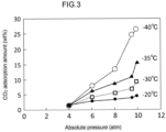
- Example 3 The experimental method followed that of Example 2, with the adsorption temperature varied at -40°C, -35°C, -30°C, and -20°C to measure the amount of CO 2 adsorption. The results are shown in Figure 3 and Table 3.
- the amount of CO 2 adsorption of the fluoro-rubber in Example 3 exceeded 13.5 wt% at -40°C under an absolute pressure of 8 atmospheres.
- the amount of CO 2 adsorption was 11.1 wt% at 9.5 atmospheres.
- the amount of CO 2 adsorption did not exceed 10 wt% at pressures below 10 atmospheres.
- the measurement device used was a Belsorp max manufactured by Microtrac-Bell.
- Example 4 the CO 2 adsorption isotherm of PDMS-h8 below freezing point, i.e., below 0°C, is shown.
- the measurement method was the same as in Reference Example 1.
- CO 2 can be adsorbed at about half the CO 2 pressure compared to 0°C. This shows that the amount of CO 2 remaining in the gas phase when CO 2 is separated and recovered is halved.
- Example 5 the CO 2 adsorption isotherm was evaluated at -78°C.
- CO 2 has a triple point at 0.52 MPa and -56.6°C. Therefore, CO 2 exhibits different physical properties above and below -56.6°C, even within the sub-zero temperature range.
- CO 2 liquefies under pressure, with the liquefaction pressure being approximately 10 atmospheres.
- the sublimation pressure is about 1 atmosphere, and when high-concentration CO 2 mixed gas is pressurized, CO 2 solidifies.
- the adsorption operation is performed at approximately one-tenth of the pressure compared to around -40°C. Since the vapor pressure of CO 2 is also lower, the concentration of CO 2 remaining in the gas phase can be reduced.
- Example 5 The samples in Example 5 were the KMP-598 used in Example 2 and a homemade PDMS rubber powder (PDMS_Ph_DIPE). PDMS_Ph_DIPE was prepared as follows.
- PDMS molecular weight: 57,000
- polyphenylmethylpolysiloxane viscosity: 500 cSt
- 10 wt% of dicumyl peroxide was added to the mixed solution, which was then heated at 150°C for 12 hours and crushed in a cryogenic grinder (average particle size: 130 ⁇ m).
- PDMS_Ph_DIPE has a glass transition temperature of -120°C, an SP value of 7.6 (cal/cm3) 0.5 , and an elastic modulus of 2 MPa at 25°C.
- the amount of CO 2 adsorption into KMP-598 was 32 wt% at an absolute pressure of 97 kPa, and PDMS_Ph_DIPE also showed a CO 2 adsorption amount of over 30 wt%. In both cases, the CO 2 adsorption amount at a pressure of 35 kPa exceeded 10 wt%, indicating that the partial pressure of CO2 can be reduced to 0.35 atmospheres or less.
- Example 6 the CO 2 adsorption isotherm at -78°C for the NBR used in Example 2 was evaluated.
- the adsorption to NBR at a temperature of -78°C was approximately half that of Example 5. This is due to the fact that the glass transition temperature of NBR is around - 35°C, and it hardens at low temperatures.
- the sample used was vacuum-dried activated carbon (Granular Shirasagi WH5C) manufactured by Osaka Gas Chemicals Co., Ltd.
- the measurement conditions were the same as those in Example 4.
- activated carbon In the case of activated carbon, a large amount of CO 2 is adsorbed. However, as is clear from the adsorption isotherm, activated carbon has a large adsorption pressure at low pressure, and even under a reduced pressure of -70 kPa (approximately 30 kPa as absolute pressure), 40 wt% of CO 2 is adsorbed on the activated carbon. Further reduction in pressure is required to desorb this.
- vacuum-dried activated carbon was used in the experiment, water is strongly adsorbed into the micropores of activated carbon, so the adsorption performance decreases even with the inclusion of even a small amount of water. On the other hand, such deterioration does not occur with hydrophobic rubber.
- Example 7 the CO 2 adsorption isotherm at -96°C was evaluated.
- the measurement method was the same as in Example 4, and the following four types of samples were used.
- the average particle size of all four types was 130 ⁇ m.
- the measurement results are shown in Table 4.
- the SP values of the samples used in Example 7 were in the range of 7.3 (cal/cm 3 ) 0.5 or more and 7.6 (cal/cm 3 ) 0.5 or less, and the glass transition temperatures were near -115°C.
- the elastic modulus at 25°C was 0.034 MPa for PDMS_h15, 3.0 MPa for PDMS_PDE and PDMS_Ph_DIPE, and 0.04 MPa for PDMS_d8.
- the elastic modulus at -96°C was in the range of 5 MPa or more and 45 MPa or less.
- PDMS_d8 has a CO 2 adsorption amount exceeding 10 wt% at -96°C. Only PDMS_d8 can reduce the partial pressure of CO 2 to about 20 kPa.
- the elastic modulus of PDMS_d8 is 9 MPa at -90°C and about 15 MPa at -96°C. That is, PDMS_d8 has an elastic modulus of 20 MPa or less and is still soft, so it can adsorb a lot of CO 2 .
- the PDMS rubber used in Example 1 has an elastic modulus of over 40 MPa at -96°C, resulting in a small amount of CO 2 adsorption.
- PDMS_h15 is a substance closer to a liquid than a rubber. In fact, PDMS_h15 has an elastic modulus of 5 MPa at -96°C. Even in such cases, the amount of CO 2 adsorbed is small at low temperatures.
- the CO 2 adsorbent of the present invention it is desirable for the CO 2 adsorbent of the present invention to have an elastic modulus of 40 MPa or less at the adsorption temperature.
- the CO 2 adsorbent it is not an essential feature of the present invention that the CO 2 adsorbent have an elastic modulus of 40 MPa or less at the adsorption temperature.
- the present invention provides a CO 2 adsorbent suitable for recovering CO2 from a mixed gas containing a high concentration of CO 2 , as well as a CO 2 separation and recovery method using this adsorbent.
- CO 2 separation and recovery are crucial for reducing greenhouse gas emissions, and this invention contributes to the prevention of global warming.
- the present invention reduces the energy costs required for CO 2 recovery, particularly lowering the cost of regenerating the adsorbent. Therefore, this invention significantly contributes to industrial development.
Landscapes
- Chemical & Material Sciences (AREA)
- Analytical Chemistry (AREA)
- Chemical Kinetics & Catalysis (AREA)
- Organic Chemistry (AREA)
- Engineering & Computer Science (AREA)
- General Chemical & Material Sciences (AREA)
- Oil, Petroleum & Natural Gas (AREA)
- Solid-Sorbent Or Filter-Aiding Compositions (AREA)
Abstract
A CO2 adsorbent comprising of rubber having a glass transition temperature of - 150°C or more and -10°C or less, an SP value of 7 (cal/cm3) 0.5 or more and 10.5 (cal/cm3) 0.5 or less, and an elastic modulus at 25°C of 0.03 MPa or more and 5 MPa or less.
Description
- The present invention relates to a CO2 adsorbent and a CO2 separation and recovery method using the same.
- In order to prevent global warming, separation and recovery of carbon dioxide gas (CO2) is an extremely important issue. However, CO2 separation and recovery methods and their conditions vary greatly depending on the source and concentration of CO2, as described below.
- In exhaust gas after air combustion, such as boiler exhaust gas, the CO2 concentration is usually 15 wt% or less. In such cases, CO2 recovery is generally performed using strong adsorbent such as amine adsorbent. For example, such adsorbent is disclosed in
Patent Documents 1 to 4, and such CO2 recovery is disclosed inPatent Document 5. - Strong adsorbent generally requires large amounts of thermal energy when desorbing CO2. However, if the CO2 concentration in the mixed gas is low and CO2 can be separated with a small amount of adsorbent, this energy problem is less. Therefore, when CO2 concentrations are low, it is effective to separate CO2 using small amount of strong adsorbent. For example, the strong adsorbent is effective when removing CO2 from a gas mixture to produce gas products.
- On the other hand, from the perspective of greenhouse gas separation, separation and recovery of low-concentration CO2 is not very efficient. This is because the desorption energy is large relative to the amount of CO2 separated.
- From the perspective of reducing greenhouse gas emissions, which also takes desorption energy efficiency into consideration, there is a strong desire to separate and recover CO2 with low energy from high-concentration CO2 sources such as natural gas and associated gas separation processes.
- This natural gas and associated gas separation process can be classified as follows depending on the CO2 concentration.
- In this case, there is no need to separate CO2, because if the CO2 concentration is less than 2%, there is no possibility of clogging even in polar pipelines. However, when producing liquefied natural gas (LNG), the Acid Gas Removal (AGR) process is applied before the cryogenic separation method is applied.
- Older equipment used molten potassium carbonate, but this is being replaced by AGR processes using amine solvents. The adsorption properties of amine solvents are regenerated by heat. Therefore, when an amine solvent is used, maintenance of the equipment is easy. On the other hand, when molten potassium carbonate is used, the problem of corrosion of steel often arises.
- An organic solvent such as propylene carbonate (PC) is used as the adsorbent. If the CO2 concentration is high, a large amount of thermal energy is required to regenerate the amine solvent. Therefore, the AGR process cannot be used.
- Currently, it is difficult to develop a separation process. There are high expectations for new CO2 separation technology.
-
- Patent Literature 1 :
JP2021-3664 - Patent Literature 2 :
JP2020-58967 - Patent Literature 3 :
JP2020-69417 - Patent Literature 4 :
JP2019-147099 - Patent Literature 5 :
JP2021-171744 - Under these circumstances, there is a need to separate CO2, which is contained in natural gas by 30% or more, to reduce the CO2 concentration to 2% or less. In addition to natural gas, mixed gases containing high concentrations of CO2 are also generated at thermal power plants and biogas production. There is a desire for a technology to recover high-concentration CO2 at low cost.
- The method of recovering CO2 using an organic solvent as an adsorbent requires the mixed gas to be dissolved into high-pressure microbubbles. Therefore, there is a problem in that energy loss is large and a part of the organic solvent is volatilized, so that the cost of recovering the organic solvent is also required.
- In view of the above background, the object of the present invention is to provide a CO2 adsorbent suitable for recovering CO2 from a mixed gas containing a high concentration of CO2, and a CO2 separation and recovery method using the same.
- The features of the present invention for solving the problems are shown below.
- A CO2 adsorbent comprising rubber having a glass transition temperature of -150°C or more and -10°C or less, an SP value of 7 (cal/cm3) 0.5 or more and 10.5 (cal/cm3) 0.5 or less, and an elastic modulus at 25°C of 0.03 MPa or more and 5 MPa or less.
- The CO2 adsorbent according to the
feature 1, wherein the glass transition temperature of the rubber is -125°C or more and -20°C or less. - The CO2 adsorbent according to the
feature - The CO2 adsorbent according to any one of the
features 1 to 3, wherein the elastic modulus of the rubber at 25°C is 0.1 MPa or more and 4.5 MPa or less. - The CO2 adsorbent according to any one of the
features 1 to 4, wherein the rubber is made of PDMS. - The CO2 adsorbent according to any one of the
features 1 to 5, wherein a thickness of the rubber is 0.1 mm or more and 5 mm or less. - The CO2 adsorbent according to any one of the
features 1 to 5, wherein the rubber is in a powder form with an equivalent spherical diameter of 0.002 mm or more and 0.1 mm or less, - A method for separating and recovering CO2 from a mixed gas, comprising:
- Bringing a mixed gas containing CO2, under a pressure of 1 MPa to 10 MPa and at a subzero temperature, into contact with the rubber according to any one of
claims 1 to 7; and - After bringing the mixed gas into contact with the rubber, isolating the rubber from the mixed gas, and then desorbing CO2 from the rubber in an environment with a pressure lower than the pressure at which the mixed gas was brought into contact with the rubber, and within the range of 0.1 MPa to 5 MPa.
- According to the present invention, a CO2 adsorbent suitable for recovering CO2 from a mixed gas containing a high concentration of CO2 and a CO2 separation and recovery method using the same are provided.
- As a result, the present invention reduces the energy cost required for CO2 recovery. In particular, the cost of regenerating the adsorbent is reduced, making it possible to contribute to the reduction of greenhouse gas emissions.
-
-
FIG. 1 is a flowchart showing the CO2 separation and recovery method of the present invention. -
FIG. 2 is a characteristic diagram showing the CO2 adsorption characteristics of PDMS rubber. -
FIG. 3 is a characteristic diagram showing the temperature and pressure dependence of the amount of CO2 adsorbed by fluoro-rubber. -
FIG. 4 is a characteristic diagram showing the temperature and pressure dependence (adsorption isotherm) of the amount of CO2 adsorbed by PDMS rubber. -
FIG. 5 is a characteristic diagram showing the temperature and pressure dependence (adsorption isotherm) of the amount of CO2 adsorbed by PDMS rubber. -
FIG. 6 is a characteristic diagram showing the CO2 adsorption isotherm of rubber at -78°C. -
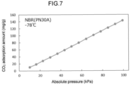
FIG. 7 is a characteristic diagram showing a CO2 adsorption isotherm of NBR at - 78°C. -
FIG. 8 is a characteristic diagram showing the CO2 adsorption isotherm of activated carbon (WH5C) at -78°C. - Hereinafter, embodiments for carrying out the present invention will be described with reference to the drawings. The expressions A to B that appear in a sentence indicate A or more and B or less.
- In
Embodiment 1, a CO2 adsorbent made of rubber whose glass transition temperature, SP value (Solubility Parameter), and elastic modulus are numerically specified will be described. - Here, "rubber" refers to a polymer that exhibits entropic elasticity at room temperature.
- The adsorption power of rubber for CO2 is generally not necessarily large, and high pressure is required to adsorb CO2 at room temperature.
- However, the inventors of the present invention discovered the followings through extensive experiments.
- The rubber with a low glass transition temperature can adsorb and desorb CO2 at freezing temperatures, where its vapor pressure is low. This rubber can adsorb 20 wt% or more of CO2 at relatively low pressure.
- Additionally, in order to efficiently adsorb a large amount of CO2, the SP value and elastic modulus of the rubber need to be within a predetermined range.
- Rubber in
embodiment 1 has a glass transition temperature of -150°C or higher and -10°C or lower, an SP value of 7.0 (cal/cm3)0.5 or higher and 10.5 (cal/cm3)0.5 or lower, and an elastic modulus at 25°C of 0.03 MPa or higher and 5 MPa or lower. - When the glass transition temperature of the rubber is in the range of -150°C or higher and -10°C or lower, more preferably -125°C or higher and -20°C or lower, the volume elastic modulus of the rubber during CO2 adsorption becomes small. This allows the rubber to absorb a large amount of CO2 even at low temperatures, such as below the freezing point of water.
- The volume elastic modulus of rubber is proportional to the elastic modulus (usually tensile elastic modulus) if the Poisson's ratio remains constant. The glass transition temperature of rubber refers to the phenomenon where the elastic modulus sharply increases when the temperature is lowered. At temperatures above the glass transition temperature, rubber becomes softer and is more likely to adsorb CO2. If the glass transition temperature is below -20°C, the partial pressure of CO2 becomes moderately small, making it more preferable for the absorption of a large amount of CO2. However, regardless of the type of rubber, the elastic modulus increases significantly at very low temperatures, so temperatures above -125°C are more preferable.
- The SP value of the rubber is 7.0 (cal/cm3) 0.5 or more and 10.5 (cal/cm3) 0.5 or less, more preferably 7.3 (cal/cm3) 0.5 or more and 7.6 (cal/cm3) 0.5 or less. When the SP value of the rubber is within this range, the affinity of the rubber for CO2 increases and a large amount of CO2 can be adsorbed within the rubber. The reason why the SP value is set to 7.3 (cal/cm3) 0.5 or more and 7.6 (cal/cm3) 0.5 or less as a more preferable condition is as follows. The SP value near the critical point of CO2 is 3.9 (cal/cm3)0.5. On the other hand, at around 0°C and 5 atm, it is 7.3 (cal/cm3) 0.5, and at -10°C and around 3 atm, it increases to 7.6 (cal/cm3) 0.5. The SP value of CO2 is 8.8 (cal/cm3)0.5 at -40°C, and increases to around 9.4 (cal/cm3)0.5 at temperatures below this temperature. However, below -56.6°C, it loses its properties as a liquid, so the SP value cannot be defined. The SP value of CO2 increases as the temperature decreases, but it also increases as the pressure increases. For example, even at -30°C, at 50 atmospheres, the SP value of CO2 is 8.5 (cal/cm3)0.5. In the CO2 separation and recovery method of the present invention, it is necessary to adsorb CO2 at sub-zero temperatures and high pressure. Therefore, it is desirable for the SP value of the rubber to be close to the SP value of CO2 under these conditions. However, in the present invention, the preferred range of SP values is indicated for the value at 25°C. This is because data on the SP values of rubber at sub-zero temperatures are not necessarily comprehensive. Additionally, like CO2, the SP value of rubber also increases with decreasing temperature.
- A soft rubber whose elastic modulus is in the range of 0.03 MPa or more and 5 MPa or less, more preferably 0.1 MPa or more and 4.5 MPa or less at 25° C., easily expands in volume when CO2 is adsorbed. This allows a large amount of CO2 to be adsorbed within the rubber. This flexibility at room temperature of 25°C makes rubber highly useful as a CO2 adsorbent.
- From the above characteristics, the rubber of
Embodiment 1 is a CO2 adsorbent suitable for recovering CO2 from a mixed gas containing a high concentration of CO2. - The rubber of
Embodiment 1 is a CO2 adsorbent suitable for adsorbing CO2 from a high-pressure mixed gas and desorbing it by reducing the pressure to recover CO2. Furthermore, it is a CO2 adsorbent suitable for increasing recovery efficiency by adsorbing CO2 from a mixed gas at low temperatures and desorbing it under reduced pressure to recover CO2. - Examples of the rubber that satisfies the above conditions include one or more selected from fluorine-based rubber, polysiloxane-based rubber, butyl rubber, natural rubber, silicone, and the like. Among these rubbers, polysiloxane rubbers can be particularly preferably used. As the polysiloxane, for example, dimethylpolysiloxane (PDMS) and diethylpolysiloxane are used. In particular, a soft PDMS rubber with a low elastic modulus can perform extremely high CO2 adsorption at low temperatures around -80°C, where the vapor pressure of CO2 approaches atmospheric pressure, as shown in the examples.
- As dimethylpolysiloxane, one in which a methyl group is partially substituted by other reactive groups (e.g. phenyl, ethyl or vinyl groups) may be used. Similarly, as diethylpolysiloxane, one in which a portion of the ethyl group is substituted by other reactive groups (e.g., phenyl, methyl, or vinyl groups) may be used. One type of polysiloxane may be used, or a combination of multiple types may be used.
- From the viewpoint of further increasing the adsorption amount of CO2 at low temperatures, it is preferable that the rubber contains a certain amount of diethyl. For example, PDMS (dimethylpolysiloxane) in which some of the reactive groups are substituted with ethyl may be used. Further, by using PDMS and diethylpolysiloxane together, the rubber may contain a certain amount of diethyl.
- The rubber with an SP value of 10.5 (cal/cm3)0.5 or less are generally hydrophobic, but some of them tend to adsorb water. In such cases, by making the rubber hydrophobic, it is possible to adsorb a large amount of CO2 at sub-zero temperatures. At subzero temperatures, water tends to adsorb to the rubber interface and voids, and adsorption performance decreases if a small amount of water is mixed in. However, by adsorbing hydrophobic molecules such as decane to the rubber, water adsorption can be suppressed. This makes it easier for the rubber to maintain a high adsorption power for CO2. The contact angle of water on the surface of the rubber (adsorbent) may be 80° or more and 150° or less.
- Further, when the rubber is in powder form, the surface area increases and CO2 can be adsorbed quickly.
- When the rubber is in powder form, the average particle diameter (equivalent sphere diameter) of the rubber is, for example, 0.5 mm or less, and preferably 0.1 mm or less, from the viewpoint of CO2 adsorption rate and desorption rate. The lower limit of the average particle diameter of the rubber is, for example, 0.002 mm or more, preferably 0.01 mm or more. In particular, a polysiloxane rubber such as PDMS, which is powdered to have the average particle diameter as described above, can be preferably used. The average particle diameter of the rubber is the average equivalent sphere diameter observed by microscopy using a TEM or SEM. If the powdered rubber is placed in a suitable cloth bag (for example, a nylon cloth bag) and used as an adsorbent, handling becomes easier. In this case, the rubber having an equivalent sphere diameter of 0.001 mm or more can be used. For example, when using the powdered rubber in a cloth bag woven from twisted fibers with a fiber diameter of about 0.03 mm, there is no problem as the adsorbent even if the average particle diameter of the rubber is about 0.002 mm.
- The shape of the rubber is not limited to powder, and may be, for example, a thick plate, an angular shape, or a pellet. The CO2 adsorbed by the rubber is desorbed from the vicinity of the surface layer of the rubber at a diffusion-controlled rate. In rubber, CO2 is desorbed at a high speed in a portion at a depth of 2.5 mm or less from the surface layer (that is, a portion within 2.5 mm from the surface layer). Therefore, from the viewpoint of high-speed CO2 desorption, the thickness of the rubber is preferably 5 mm or less. The lower limit of the thickness of the rubber is not particularly limited, but from the viewpoint of ease of handling and stability of quality, it is preferably 0.1 mm or more. For example, if the rubber is rectangular in shape and can be conceived of in the vertical, horizontal, and height directions, "rubber thickness" represents the shortest of the length in the vertical direction, length in the horizontal direction, and length in the height direction.
- Conventional CO2 separation technology that uses organic solvents such as propylene carbonate (PC) as adsorbent (absorbent) requires the gas mixture to be dissolved in high-pressure microbubbles. Therefore, such conventional CO2 separation technology has a large energy loss. Furthermore, since a part of the organic solvent evaporates, the cost of recovering the organic solvent is also incurred.
- In contrast, in the CO2 separation method using rubber according to the first embodiment of the present invention, the rubber is solid and easy to handle. Furthermore, this CO2 separation method has the advantage that loss of adsorbent is small, the amount of CO2 adsorbed is large, and the device can be made smaller. Further, when the rubber is powder, the specific surface area is large and the rate of adsorption and desorption of CO2 increases.
- In
embodiment 2, a method for separating and recovering CO2 using the rubber ofembodiment 1 will be described with reference toFigure 1. Figure 1 shows a flow chart of an example of a method for separating and recovering CO2. - The CO2 separation and recovery method of
Embodiment 2 is a method for separating and recovering CO2 that includes the following steps. - A mixed gas contact step (Step S02) in which the rubber of
Embodiment 1 is placed in a mixed gas containing CO2, where the pressure is between 1 MPa and 10 MPa and the temperature is below freezing. A mixed gas isolation step (Step S03) in which the rubber is isolated from the mixed gas after the mixed gas contact step. A desorption step (Step S04) in which CO2 is desorbed from the rubber in an environment where the pressure is lower than the pressure in the mixed gas contact step and is between 0.1 MPa and 5 MPa. - The mixed gas contact step involves supplying the mixed gas to the rubber placed within a containment vessel (e.g., an adsorption tower), thereby bringing the mixed gas into contact with the rubber. The mixed gas is supplied to the containment vessel under a pressure of between 1 MPa and 10 MPa and at a temperature below freezing. During the gas contact step, CO2 is adsorbed onto the rubber. The temperature of the mixed gas is, for example, between -50°C and 0°C, preferably between -40°C and -30°C. The mixed gas contact step is carried out for a duration sufficient for CO2 to be adequately adsorbed onto the rubber (e.g., between 5 minutes and 2 hours).
- In the mixed gas isolation step, the supply of the mixed gas to the containment vessel is stopped.
- In the desorption step, for example, by opening the pressure reducing valve, the pressure inside the containment vessel is adjusted to be lower than the pressure in the mixed gas contact step and to be between 0.1MPa and 5MPa. As the pressure inside the containment vessel decreases, CO2 desorbs from the rubber. The desorption step is carried out over a period (e.g., 1 minute to 1 hour) sufficient for CO2 to desorb from the rubber.
- The CO2 concentration in the mixed gas used in the CO2 separation and recovery method of the present invention is, for example, 20-70 vol%.
- The CO2 separation and recovery method using the solid rubber adsorbent of the present invention has a fast adsorption rate, a high adsorption capacity, and does not cause evaporation of the adsorbent during desorption. Therefore, the method of the present invention does not require recovery of the adsorbent. Thus, the method of the present invention is highly advantageous compared to methods that use organic solvents such as PC to remove CO2 from natural gas containing high concentrations of CO2.
- When removing CO2 from natural gas, the primary pressure of the produced gas is extremely high, making it easy to cool by heat exchange and decompression. By supplying such low-temperature mixed gas to a container (adsorption tower) equipped with the CO2 adsorbent of the present invention, CO2 can be separated. Additionally, the separated CO2 can be easily recovered.
- In the production of biogas, the mixed gas is currently pressurized to about 8 atmospheres, resulting in methane containing 40 wt% CO2, similar to the situation with natural gas containing high concentrations of CO2.
- To separate CO2 from methane, water is used as an adsorbent to reduce equipment costs. However, even under 10 atmospheres of pressure, the partial pressure of CO2 is only 4 atmospheres, and the solubility of CO2 at room temperature is less than 4%. The dissolution of CO2 generates carbonic acid, which lowers the pH and poses a corrosion problem.
- On the other hand, according to the present invention, CO2 can be efficiently recovered through pressurization, heat exchange, and cooling. Additionally, the adsorbent of the present invention has a high adsorption capacity, allowing for the miniaturization of the adsorption tower, thus reducing the capital investment required for the removal of large quantities of CO2.
- As understood from the above description, the CO2 separation and recovery method according to the present invention comprises:
- a mixed gas contact step of bringing a mixed gas containing CO2, with a pressure of 1 MPa to 10 MPa, and at sub-zero temperatures into contact with rubber, and
- a desorption step, after the mixed gas contact step, of isolating the rubber from the mixed gas and desorbing CO2 from the rubber in an environment where the pressure is lower than that of the mixed gas contact step and is between 0.1 MPa and 5 MPa.
- In Example 1, the PDMS rubber produced using the PDMS rubber preparation kit was used to evaluate the properties when CO2 was adsorbed and desorbed.
- The PDMS rubber preparation kit used was SYLGARDTM 184 Silicone Elastomer manufactured by DOW Inc. The prepared PDMS rubber was cut into 5 mm square pieces. The prepared PDMS rubber had a glass transition temperature of -125°C, an SP value of 7.6 (cal/cm3)0.5, and an elastic modulus of 2.0 MPa at 25°C. After CO2 was adsorbed into the 5 mm square PDMS rubber at a temperature of 25°C and 30 atm of CO2, the PDMS rubber was isolated from the high-pressure CO2 gas. In the following experiments including Example 1, adsorption was performed using a gas with a CO2 concentration of 100%. After that, the CO2 adsorbed by the PDMS rubber was leaked into a vacuum container. The pressure change in the sample container at that time is shown in
Figure 2 . This pressure change includes all the CO2 in the sample container. In other words, it contains CO2 that was adsorbed onto the PDMS rubber and CO2 that was present in the gaps between the PDMS rubber. The change in pressure that occurs a few seconds after the leak is due to an increase in pressure caused by CO2 being released from the PDMS rubber. These results show that at around 10 atmospheres, more than 80% of the CO2 is desorbed in about 5 minutes. - In PDMS rubber with an equivalent sphere diameter of 500 µm, desorption of CO2 occurs within a few seconds. Even in PDMS rubber with a side length of 5 mm (adsorbent thickness of 5 mm), the desorption speed of CO2 from the surface layer is fast. The CO2 adsorbed inside is desorbed slightly later than the CO2 on the surface layer. The results shown in
Figure 2 indicate that if the thickness of the adsorbent is 5 mm or less, a sufficient desorption speed (within 5 minutes) for the regeneration of the CO2 adsorbent can be achieved. - In Example 2, the CO2 adsorption amount of various rubbers at -40°C was evaluated. Three types of samples were used: KMP-598 (PDMS rubber powder manufactured by Shin-Etsu Silicone Co., Ltd., particle size: 2-30 µm), NBR (NBR powder (PN30A) manufactured by JSR Corporation, sphere equivalent diameter: 400 µm), and PDMS-h8 (homemade PDMS rubber powder, average particle size: 130 µm).
- PDMS-h8 is a sample obtained by adding 8 g of hexane to 2 g of PDMS macromer during the curing of a two-liquid mixed PDMS rubber preparation kit (SYLGARDTM 184 Silicone Elastomer), followed by curing and drying. The elastic modulus of PDMS-h8 at room temperature (25°C) is 0.04 MPa. This is about 100 times smaller than that of normal PDMS rubber, making PDMS-h8 a soft rubber. The elastic modulus of KMP-598 and NBR at room temperature (25°C) is approximately 4 MPa and approximately 1 MPa, respectively.
- The glass transition temperatures of KMP-598, PDMS-h8 and NBR are near -125°C, -110°C and -25°C, respectively, and the SP values are 7.3 (cal/cm3) 0.5, 7.3 (cal/cm3) 0.5 and 10.3 (cal/cm3) 0.5.
- These rubbers, each weighing 10 grams, were used to adsorb CO2 at -40°C. Subsequently, the CO2 was desorbed at room temperature in a vacuum buffer container (1 L). The amount of CO2 adsorbed by the rubber was calculated based on the pressure increase within the buffer container. The results are shown in Table 1. The pressure in Table 1 represents the absolute pressure of CO2 during adsorption.
- KPM-598 adsorbed 10.9 wt% of CO2 at 8 atmospheres. The softer PDMS-h8 adsorbed an even greater amount, 12.38 wt% of CO2. Furthermore, when the pressure for PDMS-h8 was increased to 8.8 atmospheres and 10.0 atmospheres, the CO2 adsorption increased significantly to 16.15 wt% and 25.20 wt%, respectively.
- NBR also adsorbed 21.20 wt% CO2 at 10 atmospheres.
- These results indicate that rubbers with a glass transition temperature below -40°C, an SP value of 7.0 to 10.5 (cal/cm3)0.5, and an elastic modulus ranging from 0.03 MPa to 5 MPa at 25°C can adsorb more than 10 wt% of CO2 at low temperatures.
[Table 1] Item KMP-598 PDMS_h8 NBR Glass transition temperature(°C ) -125 -110 -25 SP value (cal/cm3)0.5 7.3 7.3 10.3 Pressure (atm) 8.0 8.0 8.8 10.0 10.0 CO2 adsorption amount (wt%) 10.90 12.38 16.15 25.20 21.20 - In Comparative Example 1, the amount of CO2 adsorption at -40°C was measured for NR (
rubber powder # 2500, sphere equivalent diameter: 400 µm, manufactured by Toyo Rubber Chip Co., Ltd.), a natural rubber powder derived from waste tires. The results are shown in Table 2. The glass transition temperature of the rubber component of this powder sample is around -70°C, and the SP value is about 8.2 (cal/cm3)0.5. The elastic modulus of NR in Comparative Example 1 at 25°C is about 20 MPa.[Table 2] Item NR Glass transition temperature(°C) -70 SP value (cal/cm3)0.5 8.2 Pressure (atm) 9.5 CO2 adsorption amount (wt%) 4.09 - In Comparative Example 1, the CO2 adsorption amount at an absolute pressure of 9.5 atm was 4.09 wt%. It is considered that natural rubber easily adsorbs CO2, but the CO2 adsorption amount is smaller in rubber that has been cured by vulcanization or carbon additives.
- The PDMS rubber used in Example 1 has a modulus of elasticity of 42 MPa at - 90°C. The modulus of elasticity of the PDMS rubber used in Example 1 decreases to 27 MPa, 18 MPa, 13 MPa, and 10 MPa at -80°C, -70°C, -60°C, and -50°C, respectively, and the modulus of elasticity is 4.4 MPa at 25°C. When CO2 is adsorbed, the rubber undergoes volumetric swelling. Therefore, it is easier to adsorb CO2 when a rubber with a high modulus of elasticity is used and in a temperature range where the modulus of elasticity is high.
- In Example 3, the temperature dependence of the amount of CO2 adsorption on fluoro-rubber was evaluated. The sample used was fluoro-rubber powder with an average particle size of 130 µm (Daikin Industries, Ltd. G-701BP, which was ground to a size below 500 µm using a cryogenic grinder).
- The experimental method followed that of Example 2, with the adsorption temperature varied at -40°C, -35°C, -30°C, and -20°C to measure the amount of CO2 adsorption. The results are shown in
Figure 3 and Table 3. The amount of CO2 adsorption of the fluoro-rubber in Example 3 exceeded 13.5 wt% at -40°C under an absolute pressure of 8 atmospheres. In contrast, at -35°C, the amount of CO2 adsorption was 11.1 wt% at 9.5 atmospheres. At -30°C and -20°C, the amount of CO2 adsorption did not exceed 10 wt% at pressures below 10 atmospheres. - These results indicate that a lower temperature yields a higher amount of CO2 adsorption, making it desirable for CO2 separation and recovery.

- In Reference Example 1, the CO2 adsorption isotherm of PDMS-h8 used in Example 2 was measured.
- The measurement device used was a Belsorp max manufactured by Microtrac-Bell.
- The results are shown in
Figure 4 . - When the temperature of CO2 was set at 4°C, 6°C, and 8°C, which are relatively high for CO2 adsorption, and the absolute pressure of CO2 was raised to 30 atm or more, the amount of CO2 adsorption was 30 wt% or more. However, under such conditions, the partial pressure of unabsorbed CO2 in the mixed gas becomes high. For this reason, CO2 in the gas phase cannot be adsorbed efficiently. The reason for this is that, for example, when using an adsorbent to reduce the CO2 concentration from a mixed gas with a CO2 concentration of 70% to 10% (10% as partial pressure), the total gas pressure needs to be 300 atm, but adsorption operation at such high pressure is not realistic. It is desirable for the adsorbent to achieve a high adsorption amount at a low CO2 partial pressure, and it is preferable that the adsorption operation can be performed at a low temperature.
- In Example 4, the CO2 adsorption isotherm of PDMS-h8 below freezing point, i.e., below 0°C, is shown. The measurement method was the same as in Reference Example 1.
- The results are shown in
Figure 5 . As is clear fromFigure 5 , below freezing point, a large amount of adsorption was observed even when the CO2 pressure was low. It shows that below freezing point is desirable for efficient CO2 adsorption. - For example, at -38°C, CO2 can be adsorbed at about half the CO2 pressure compared to 0°C. This shows that the amount of CO2 remaining in the gas phase when CO2 is separated and recovered is halved.
- In Example 5, the CO2 adsorption isotherm was evaluated at -78°C.
- CO2 has a triple point at 0.52 MPa and -56.6°C. Therefore, CO2 exhibits different physical properties above and below -56.6°C, even within the sub-zero temperature range.
- Around -40°C, CO2 liquefies under pressure, with the liquefaction pressure being approximately 10 atmospheres.
- Conversely, around -80°C, the sublimation pressure is about 1 atmosphere, and when high-concentration CO2 mixed gas is pressurized, CO2 solidifies.
- Thus, the adsorption operation is performed at approximately one-tenth of the pressure compared to around -40°C. Since the vapor pressure of CO2 is also lower, the concentration of CO2 remaining in the gas phase can be reduced.
- The samples in Example 5 were the KMP-598 used in Example 2 and a homemade PDMS rubber powder (PDMS_Ph_DIPE). PDMS_Ph_DIPE was prepared as follows.
- PDMS (molecular weight: 57,000) with vinyl groups at both ends and polyphenylmethylpolysiloxane (viscosity: 500 cSt) were mixed at a ratio of 1:1 to obtain a mixed solution.
10 wt% of dicumyl peroxide was added to the mixed solution, which was then heated at 150°C for 12 hours and crushed in a cryogenic grinder (average particle size: 130 µm). - PDMS_Ph_DIPE has a glass transition temperature of -120°C, an SP value of 7.6 (cal/cm3) 0.5, and an elastic modulus of 2 MPa at 25°C.
- Measurements were performed using a Belsorp Mini manufactured by Microtrack-Bell. The experimental results are shown in
Figure 6 . - The amount of CO2 adsorption into KMP-598 was 32 wt% at an absolute pressure of 97 kPa, and PDMS_Ph_DIPE also showed a CO2 adsorption amount of over 30 wt%. In both cases, the CO2 adsorption amount at a pressure of 35 kPa exceeded 10 wt%, indicating that the partial pressure of CO2 can be reduced to 0.35 atmospheres or less.
- This result means that when CO2 is adsorbed at 35 atmospheres, the partial pressure of CO2 can be reduced to 1% or less. It also shows that the amount of CO2 adsorption changes according to Henry's law, making it easy to desorb by reducing pressure.
- In Example 6, the CO2 adsorption isotherm at -78°C for the NBR used in Example 2 was evaluated.
- The measurement method was the same as in Example 4. The results are shown in
Figure 7 . - The adsorption to NBR at a temperature of -78°C was approximately half that of Example 5. This is due to the fact that the glass transition temperature of NBR is around - 35°C, and it hardens at low temperatures.
- In Comparative Example 2, the CO2 adsorption isotherm for activated carbon at - 78°C was evaluated.
- The sample used was vacuum-dried activated carbon (Granular Shirasagi WH5C) manufactured by Osaka Gas Chemicals Co., Ltd. The measurement conditions were the same as those in Example 4.
- The results are shown in
Figure 8 . - In the case of activated carbon, a large amount of CO2 is adsorbed. However, as is clear from the adsorption isotherm, activated carbon has a large adsorption pressure at low pressure, and even under a reduced pressure of -70 kPa (approximately 30 kPa as absolute pressure), 40 wt% of CO2 is adsorbed on the activated carbon. Further reduction in pressure is required to desorb this. In addition, although vacuum-dried activated carbon was used in the experiment, water is strongly adsorbed into the micropores of activated carbon, so the adsorption performance decreases even with the inclusion of even a small amount of water. On the other hand, such deterioration does not occur with hydrophobic rubber.
- In Example 7, the CO2 adsorption isotherm at -96°C was evaluated.
- The measurement method was the same as in Example 4, and the following four types of samples were used. The average particle size of all four types was 130µm.
- (1) PDMS_h15:
A sample prepared by adding 15 g of hexane to 2 g of PDMS macromer during the curing of a two-part mixed PDMS rubber preparation kit (SYLGARD™ 184 Silicone Elastomer), followed by cryogenic grinding. - (2) PDMS_PDE:
A sample prepared by adding dicumyl peroxide equivalent to 10 wt% of PDMS (molecular weight: 57,000) with vinyl groups at both ends, heating at 150°C for 12 hours, and then cryogenic grinding. - (3) PDMS_Ph_DIPE:
The sample described in Example 5. - (4) PDMS_d8:
A sample prepared by adding 8 g of decane to 2 g of PDMS macromer during the curing of a two-part mixed PDMS rubber preparation kit (SYLGARD™ 184 Silicone Elastomer), washing with hexane, drying, and then cryogenic grinding. - The measurement results are shown in Table 4. The SP values of the samples used in Example 7 were in the range of 7.3 (cal/cm3)0.5 or more and 7.6 (cal/cm3)0.5 or less, and the glass transition temperatures were near -115°C. The elastic modulus at 25°C was 0.034 MPa for PDMS_h15, 3.0 MPa for PDMS_PDE and PDMS_Ph_DIPE, and 0.04 MPa for PDMS_d8. The elastic modulus at -96°C was in the range of 5 MPa or more and 45 MPa or less.
[Table 4] PDMS_h15 PDMS_DIPE PDMS_Ph_DIPE PDMS_d8 Pressure (kPa) 20.4 15.3 14.3 20.9 CO2 adsorption amount (wt%) 3.1 3.8 3.0 11.5 - As shown in Table 4, only PDMS_d8 has a CO2 adsorption amount exceeding 10 wt% at -96°C. Only PDMS_d8 can reduce the partial pressure of CO2 to about 20 kPa.
- The elastic modulus of PDMS_d8 is 9 MPa at -90°C and about 15 MPa at -96°C. That is, PDMS_d8 has an elastic modulus of 20 MPa or less and is still soft, so it can adsorb a lot of CO2.
- On the other hand, the PDMS rubber used in Example 1 has an elastic modulus of over 40 MPa at -96°C, resulting in a small amount of CO2 adsorption. Even PDMS_DIPE and PDMS_Ph_DIPE, which are expected to have a high degree of crosslinking, have a small amount of CO2 adsorption.
- In addition, 15 g of hexane was added to PDMS_h15 during crosslinking, but crosslinking hardly progressed. PDMS_h15 is a substance closer to a liquid than a rubber. In fact, PDMS_h15 has an elastic modulus of 5 MPa at -96°C. Even in such cases, the amount of CO2 adsorbed is small at low temperatures.
- In summary, from the view-point of increasing the CO2 adsorption efficiency, it is desirable for the CO2 adsorbent of the present invention to have an elastic modulus of 40 MPa or less at the adsorption temperature. However, it is not an essential feature of the present invention that the CO2 adsorbent have an elastic modulus of 40 MPa or less at the adsorption temperature.
- As described above, the present invention provides a CO2 adsorbent suitable for recovering CO2 from a mixed gas containing a high concentration of CO2, as well as a CO2 separation and recovery method using this adsorbent. CO2 separation and recovery are crucial for reducing greenhouse gas emissions, and this invention contributes to the prevention of global warming.
- The present invention reduces the energy costs required for CO2 recovery, particularly lowering the cost of regenerating the adsorbent. Therefore, this invention significantly contributes to industrial development.
Claims (8)
- A CO2 adsorbent comprising rubber having a glass transition temperature of -150°C or more and -10°C or less, an SP value of 7 (cal/cm3) 0.5 or more and 10.5 (cal/cm3) 0.5 or less, and an elastic modulus at 25°C of 0.03 MPa or more and 5 MPa or less.
- The CO2 adsorbent according to claim 1, wherein the glass transition temperature of the rubber is -125°C or more and -20°C or less.
- The CO2 adsorbent according to claim 1 or 2, wherein the SP value of the rubber is 7.3 (cal/cm3) 0.5 or more and 7.6 (cal/cm3) 0.5 or less.
- The CO2 adsorbent according to any one of claims 1 to 3, wherein the elastic modulus of the rubber at 25°C is 0.1 MPa or more and 4.5 MPa or less.
- The CO2 adsorbent according to any one of claims 1 to 4, wherein the rubber is made of PDMS.
- The CO2 adsorbent according to any one of claims 1 to 5, wherein a thickness of the rubber is 0.1 mm or more and 5 mm or less.
- The CO2 adsorbent according to any one of claims 1 to 5, wherein the rubber is in a powder form with an equivalent spherical diameter of 0.002 mm or more and 0.1 mm or less.
- A method for separating and recovering CO2 from a mixed gas, comprising:Bringing a mixed gas containing CO2, under a pressure of 1 MPa to 10 MPa and at a subzero temperature, into contact with the rubber according to any one of claims 1 to 7; andAfter bringing the mixed gas into contact with the rubber, isolating the rubber from the mixed gas, and then desorbing CO2 from the rubber in an environment with a pressure lower than the pressure at which the mixed gas was brought into contact with the rubber, and within the range of 0.1 MPa to 5 MPa.
Applications Claiming Priority (2)
| Application Number | Priority Date | Filing Date | Title |
|---|---|---|---|
| JP2022025649 | 2022-02-22 | ||
| PCT/JP2023/003823 WO2023162652A1 (en) | 2022-02-22 | 2023-02-06 | Co2 adsorbent and co2 separation-collection method using same |
Publications (1)
| Publication Number | Publication Date |
|---|---|
| EP4484001A1 true EP4484001A1 (en) | 2025-01-01 |
Family
ID=87765670
Family Applications (1)
| Application Number | Title | Priority Date | Filing Date |
|---|---|---|---|
| EP23759656.4A Pending EP4484001A1 (en) | 2022-02-22 | 2023-02-06 | Co2 adsorbent and co2 separation-collection method using same |
Country Status (4)
| Country | Link |
|---|---|
| US (1) | US20250153138A1 (en) |
| EP (1) | EP4484001A1 (en) |
| JP (1) | JP7822648B2 (en) |
| WO (1) | WO2023162652A1 (en) |
Families Citing this family (3)
| Publication number | Priority date | Publication date | Assignee | Title |
|---|---|---|---|---|
| WO2025158932A1 (en) * | 2024-01-24 | 2025-07-31 | 国立研究開発法人物質・材料研究機構 | Co2 recovery absorber and co2 recovery device |
| WO2025158933A1 (en) * | 2024-01-24 | 2025-07-31 | 国立研究開発法人物質・材料研究機構 | Co2 separation system |
| WO2026088725A1 (en) * | 2024-10-22 | 2026-04-30 | 国立研究開発法人物質・材料研究機構 | Co2 separation system and co2 separation method |
Family Cites Families (8)
| Publication number | Priority date | Publication date | Assignee | Title |
|---|---|---|---|---|
| CN108380189B (en) * | 2011-09-05 | 2021-03-16 | 株式会社可乐丽 | Adsorbent material |
| KR101865771B1 (en) * | 2016-06-16 | 2018-07-04 | 연세대학교 산학협력단 | Gas separation membrane containing amphiphilic copolymer of spherical particles and method for preparing the same |
| JP6955700B2 (en) | 2018-02-27 | 2021-10-27 | 株式会社豊田中央研究所 | CO2 adsorbent |
| JP7012288B2 (en) * | 2018-08-28 | 2022-01-28 | Jfeエンジニアリング株式会社 | A selective composite gas permeable membrane having a metal-organic framework layer and a method for producing the same. |
| JP2020058967A (en) | 2018-10-05 | 2020-04-16 | 東ソー株式会社 | Carbon dioxide separation composition |
| JP2020069417A (en) | 2018-10-30 | 2020-05-07 | 東ソー株式会社 | Carbon dioxide absorbing composition |
| JP7240637B2 (en) | 2019-06-25 | 2023-03-16 | 株式会社豊田中央研究所 | CO2 adsorbent |
| JP7452231B2 (en) | 2020-04-30 | 2024-03-19 | 株式会社豊田中央研究所 | Carbon dioxide adsorbents, carbon dioxide capture devices, and hydrocarbon generation systems |
-
2023
- 2023-02-06 US US18/834,091 patent/US20250153138A1/en active Pending
- 2023-02-06 JP JP2024502974A patent/JP7822648B2/en active Active
- 2023-02-06 EP EP23759656.4A patent/EP4484001A1/en active Pending
- 2023-02-06 WO PCT/JP2023/003823 patent/WO2023162652A1/en not_active Ceased
Also Published As
| Publication number | Publication date |
|---|---|
| US20250153138A1 (en) | 2025-05-15 |
| WO2023162652A1 (en) | 2023-08-31 |
| JP7822648B2 (en) | 2026-03-03 |
| JPWO2023162652A1 (en) | 2023-08-31 |
Similar Documents
| Publication | Publication Date | Title |
|---|---|---|
| US20250153138A1 (en) | Co2 adsorbent and co2 separation and recovery method using the same | |
| MY158840A (en) | Method and apparatus for removal of oil from utility gas stream | |
| CN104271715B (en) | Method and apparatus for producing liquefied natural gas | |
| CN1547504A (en) | Adsorbent for separating nitrogen from mixed gas of oxygen and nitrogen, and process for producing nitrogen by using same | |
| EP2420551A1 (en) | Use of a microporous crystalline material of zeolitic nature with rho structure in natural gas processing | |
| JP2006509622A5 (en) | ||
| KR950010265B1 (en) | How to Absorb Multicomponent Gas Absorption | |
| JP2987686B2 (en) | Gas storage method | |
| EP2700439A1 (en) | System and method for processing greenhouse gases | |
| JP7813063B2 (en) | CO2 Separation System | |
| EP2644249B1 (en) | System and method for producing carbon dioxide | |
| JPWO2023162652A5 (en) | ||
| KR101883878B1 (en) | Apparatus and method for removing acidic gas containing natural gas | |
| JP5901849B2 (en) | Method for separating methane and nitrogen | |
| Mabuza et al. | Low-high temperature flue gas direct injection in south African bituminous and anthracite coals | |
| JP2005177737A (en) | Activated carbon for removing siloxane, method for removing siloxane, and adsorbent for removing siloxane | |
| JP7627060B2 (en) | Combustible gas recovery method | |
| US9453174B2 (en) | Apparatuses and methods for removing impurities from a hydrocarbon stream | |
| EP2980221B1 (en) | Method for collecting isoprene contained in fermented gas, and method for producing purified isoprene | |
| US20210213418A1 (en) | Sorbent and sorption device | |
| JP4047505B2 (en) | SF6 gas recovery device | |
| CN214051036U (en) | Emergent recovery unit of electrical equipment leakage gas | |
| KR102156825B1 (en) | Pressure swing adsorption process for separation and recovery of carbon monoxide | |
| JP2008229494A (en) | Method for fixing carbon dioxide in coal seam | |
| CN103113946B (en) | Marsh gas purification system and marsh gas purification method |
Legal Events
| Date | Code | Title | Description |
|---|---|---|---|
| STAA | Information on the status of an ep patent application or granted ep patent |
Free format text: STATUS: THE INTERNATIONAL PUBLICATION HAS BEEN MADE |
|
| PUAI | Public reference made under article 153(3) epc to a published international application that has entered the european phase |
Free format text: ORIGINAL CODE: 0009012 |
|
| STAA | Information on the status of an ep patent application or granted ep patent |
Free format text: STATUS: REQUEST FOR EXAMINATION WAS MADE |
|
| 17P | Request for examination filed |
Effective date: 20240726 |
|
| AK | Designated contracting states |
Kind code of ref document: A1 Designated state(s): AL AT BE BG CH CY CZ DE DK EE ES FI FR GB GR HR HU IE IS IT LI LT LU LV MC ME MK MT NL NO PL PT RO RS SE SI SK SM TR |
|
| DAV | Request for validation of the european patent (deleted) | ||
| DAX | Request for extension of the european patent (deleted) |