EP4483979A1 - Vacuum sublimation device - Google Patents
Vacuum sublimation device Download PDFInfo
- Publication number
- EP4483979A1 EP4483979A1 EP23711114.1A EP23711114A EP4483979A1 EP 4483979 A1 EP4483979 A1 EP 4483979A1 EP 23711114 A EP23711114 A EP 23711114A EP 4483979 A1 EP4483979 A1 EP 4483979A1
- Authority
- EP
- European Patent Office
- Prior art keywords
- vacuum
- coupling
- access
- upper head
- container
- Prior art date
- Legal status (The legal status is an assumption and is not a legal conclusion. Google has not performed a legal analysis and makes no representation as to the accuracy of the status listed.)
- Granted
Links
Images


Classifications
-
- B—PERFORMING OPERATIONS; TRANSPORTING
- B01—PHYSICAL OR CHEMICAL PROCESSES OR APPARATUS IN GENERAL
- B01D—SEPARATION
- B01D7/00—Sublimation
-
- B—PERFORMING OPERATIONS; TRANSPORTING
- B01—PHYSICAL OR CHEMICAL PROCESSES OR APPARATUS IN GENERAL
- B01D—SEPARATION
- B01D3/00—Distillation or related exchange processes in which liquids are contacted with gaseous media, e.g. stripping
- B01D3/10—Vacuum distillation
Definitions
- the invention deals with a vacuum sublimation device that allows the stabilisation of a solid body to be sublimated directly on an analysable sample plate while being adaptable in height to the volume and certain boundary conditions for each sublimable solid.
- Sublimation is understood as the transition of a substance directly from the solid state to the gaseous state without going through the liquid state, being an endothermic process that occurs at temperatures and pressures below the triple point of a substance in its phase diagram, corresponding to the lowest pressure at which the substance can exist as a liquid.
- vacuum sublimation methods have wide use in the purification and recrystallisation of molecular species, including the possibility of selectively separating polymorphs/enantiomers.
- the first path requires subsequent steps towards deposition on the chosen substrates or the successive growth of the crystals towards the creation of adequate electronic connections, limiting the studies to large size crystals.
- ultra-high vacuum sublimation pieces of equipment are very specific and complex pieces of equipment, implying greater difficulty in preparing the samples in said devices, limiting the use of such devices in conventional laboratories, and furthermore, the parts that make up said devices are not interchangeable, so that if there is a defect, it would be necessary to recalibrate and repair the complete equipment instead of part by part.
- conventional sublimation pieces of equipment are made up of two parts, a container in which the solid to be sublimated is located and a glass receiver through which water circulates where the solid is deposited in a gaseous state to cool it and collect it in solid form, representing a drawback in terms of solids analysis times because the receiver part has to be subjected to solid purification and extraction processes after sublimation, as well as a drawback in terms of analysis and measurement errors derived from the passage of the solid from the receiver part to the laboratory analysis part.
- the receptor part is a unique part of each equipment, so that the distance with respect to the solid prior to sublimation located in the container is a fixed distance. This event results in the difficulty of controlling the amount of solid that is deposited in the receiver. In other words, covering the receiver part with a specific amount of solid can take a long time depending on the substances and the distance that said solid must travel in a gaseous state until it contacts the glass receiver.
- the device object of the invention can be used directly in standard laboratories, not subject to specific environmental conditions, allowing the deposition of the sublimated material, in a single step, on a variety of surfaces, substrates and/or preformed devices, without the need for intermediate steps between devices for sample analysis.
- the device object of the invention also comprises an upper head coupled to the container, being made of glass and which is equipped with a first and a second access, wherein the second access has a larger cross section than the first, equipping the upper head with a bottle head geometry.
- the first access is connected to a vacuum generating machine, both complex laboratory machines and conventional vacuum pumps, the vacuum generation flow of which can be controlled directly from the vacuum generating machine or can be controlled by means of a step element, which can be a stopcock, coupled transversely to the upper head; and by rotating it, same obstructs or allows the passage of the vacuum generation flow through the inside of the upper head from the first to the second access.
- a vacuum generating machine both complex laboratory machines and conventional vacuum pumps
- the central core is formed by an upper coupling internally linked to the second access of the upper head.
- Said coupling comprises a threaded hole through which a support is threadedly coupled by means of a threaded rod that extends superiorly from a base of said support.
- the support By rotating about its axis, the support increases or decreases its distance with respect to the coupling, and, additionally, with respect to the solid located in the container. Likewise, due to the measurement indicators, it is possible to know the distance at which the support is adjustable with respect to the sublimable solid and, additionally, with respect to the coupling.
- the coupling is equipped, in addition to a threaded hole, with an external indentation that extends around the perimeter of said coupling and where a pressure element fits, which can be an elastic pressure gasket, which favours the fastening of the coupling against the inner walls of the upper head.
- the support additionally comprises a fastening gauge that is fixed to the base by means of fastening elements, which can be screws or clamping plates.
- Said gauge can also present an essentially cylindrical geometry, also in accordance with the geometry of the base and the coupling; and it has a slot intended to house a sample receiver that collects the substances derived from the sublimation of the solid located in the container, in the lower portion thereof, directly against its surface, said sample receiver being able to be an electrode wherein the sample is analysed directly, an FET type device, a piece of paper, etc.
- the vacuum generating machine that is, the vacuum pump connected to the device
- a vacuum is generated inside said device, sublimating the substance located inside it. If the substance requires heat, to complete the sublimation process, the device can be placed on a hot surface or, for example, a silicone bath at a controlled temperature.
- the amount of material deposited by sublimation can be controlled by time, as well as by adjusting the distance between the sample collection plate and the base of the cup, or a combination of both.
- the device is depressurised to break the vacuum, depending on the nature of the substance, disconnecting the vacuum pump or passing air or an inert gas.
- Said upper head (3) is equipped, in turn, with a first access (4) intended to receive a connection means for connecting with the vacuum generating machine, a second access (5) that receives the container (1) through the upper area (2) thereof.
- the device can be equipped with a passage element (6) transversally coupled to the upper head (3) and which allows the passage of the vacuum flow coming from the vacuum generating machine between the first and second access (4, 5) of said upper head (3).
- the second access (5) has a larger cross section than the first access (4), equipping the upper head (3) with a bottle geometry.
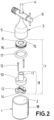
- Figure 2 shows an exploded view of the device object of the invention, wherein it can be seen that it additionally has a central core (7) that is internally coupled to the upper head (3) through the second access (5) and located inside the container (1), said central core (7) being equipped with a coupling (8) internally linked to the second access (5) of the upper head (3), a support (9) attached in a threaded manner with the coupling (8) and adjustable in height by means of a threaded rotation with respect to said coupling (8), and a sample receiver (19) located in the support (9) and intended to directly collect the samples of the solid substance in a gaseous state through the lower portion thereof.
- a central core (7) that is internally coupled to the upper head (3) through the second access (5) and located inside the container (1)
- said central core (7) being equipped with a coupling (8) internally linked to the second access (5) of the upper head (3), a support (9) attached in a threaded manner with the coupling (8) and adjustable in height by means of a threaded rotation with respect to said
- the coupling (8) comprises an external indentation (16) extending around the perimeter and a pressure gasket (17) housed in said external indentation (16) intended to fasten the coupling (8) internally against the upper head (3) through the second access (5) thereof, as well as a threaded hole (15).
- the support (9) is made up of a base (10) that incorporates a threaded rod (11) which couples with the threaded hole (15) of the coupling (8) and by rotating on its own axis allows said support (9) to be adjusted in height with respect to the coupling (8) and a gauge (12) coupled to the base (10) by means of fastening elements (13), preferably fastening screws, which is equipped with a slot (14) wherein the sample receiver (19) is supported so that the sublimated solid substance impacts and is collected against the lower wall of the sample receiver (19).
- the measurement indicators (18) of the container (1) mark the height with respect to the coupling (8) and/or with respect to the solid to be sublimated where the gauge (12) and therefore the sample receiver (19) must be established.
- Figure 3 shows an exploded perspective view of a second exemplary embodiment of the invention, wherein the fastening elements (13) are clamping plates adapted to the base (10) of the support (9) and to the fastening gauge (12), linking both elements together by means of a quick coupling instead of using screws.
Landscapes
- Chemical & Material Sciences (AREA)
- Chemical Kinetics & Catalysis (AREA)
- Sampling And Sample Adjustment (AREA)
- Vaporization, Distillation, Condensation, Sublimation, And Cold Traps (AREA)
Abstract
Description
- The object of the invention falls within the technical field corresponding to physical phenomena, specifically, to the sector belonging to the sublimation of solid bodies using vacuum.
- The invention deals with a vacuum sublimation device that allows the stabilisation of a solid body to be sublimated directly on an analysable sample plate while being adaptable in height to the volume and certain boundary conditions for each sublimable solid.
- Sublimation is understood as the transition of a substance directly from the solid state to the gaseous state without going through the liquid state, being an endothermic process that occurs at temperatures and pressures below the triple point of a substance in its phase diagram, corresponding to the lowest pressure at which the substance can exist as a liquid.
- On the one hand, vacuum sublimation methods have wide use in the purification and recrystallisation of molecular species, including the possibility of selectively separating polymorphs/enantiomers.
- On the other hand, the sublimation of molecules using UHV (Ultra High Vacuum) techniques provides studies and reactivity of said units on different substrates, where it is possible to characterise the molecular organisation and reactivity of new molecular-based materials, avoiding undesired solvents and residues.
- In the study of crystalline materials for electronic devices, the first path requires subsequent steps towards deposition on the chosen substrates or the successive growth of the crystals towards the creation of adequate electronic connections, limiting the studies to large size crystals.
- The second path requires highly specialised and complex pieces of equipment with the intention of reaching pressures below 10-7 millibars, that is, pressures below the triple point of molecular substances.
- In addition, ultra-high vacuum sublimation pieces of equipment are very specific and complex pieces of equipment, implying greater difficulty in preparing the samples in said devices, limiting the use of such devices in conventional laboratories, and furthermore, the parts that make up said devices are not interchangeable, so that if there is a defect, it would be necessary to recalibrate and repair the complete equipment instead of part by part.
- Moreover, conventional sublimation pieces of equipment are made up of two parts, a container in which the solid to be sublimated is located and a glass receiver through which water circulates where the solid is deposited in a gaseous state to cool it and collect it in solid form, representing a drawback in terms of solids analysis times because the receiver part has to be subjected to solid purification and extraction processes after sublimation, as well as a drawback in terms of analysis and measurement errors derived from the passage of the solid from the receiver part to the laboratory analysis part.
- In addition, for each of the conventional pieces of equipment, the receptor part is a unique part of each equipment, so that the distance with respect to the solid prior to sublimation located in the container is a fixed distance. This event results in the difficulty of controlling the amount of solid that is deposited in the receiver. In other words, covering the receiver part with a specific amount of solid can take a long time depending on the substances and the distance that said solid must travel in a gaseous state until it contacts the glass receiver.
- The present invention tries to offer a solution in which the sublimated solid is deposited in a receiver plate that is directly analysable, preventing errors during the transfer of conventional receiver parts to measuring plates and speeding up analysis times in laboratories of solid substances that are sublimated; at the same time that it offers a solution in which the device can be adjustable in height depending on the volume, density or surface of the solid to be sublimated, and therefore, of the receiver plate, without the need to dimensionally modify the container in which the solid is located based on the volume thereof.
- Likewise, the device object of the invention can be used directly in standard laboratories, not subject to specific environmental conditions, allowing the deposition of the sublimated material, in a single step, on a variety of surfaces, substrates and/or preformed devices, without the need for intermediate steps between devices for sample analysis.
- In addition, the common glassware components together with the use of support parts obtained by means of 3D printing, with structural stability at temperatures less than 200 °C, preferably, make the entire system affordable for conventional characterisations and easily repairable, replaceable or modifiable, because the parts can be exchanged and adapted to each other depending on the amount to be sublimated and the surface to be used.
- 3D printing materials the thermal properties of which allow the use of the device at temperatures higher than 200 °C can also be used, that is, the device can be made up of parts that can adapt to variable external conditions, without resulting in a specific device for a temperature condition and specific pressure. Moreover, said parts do not need to be made by means of 3D printing, but can be manufactured from other material production means such as Teflon by machining.
- On this matter, the direct sublimation device intended to perform sublimation work on solid substances using vacuum comprises a container with an essentially cylindrical geometry and which is open at the upper area, wherein the solid to be sublimated using vacuum sublimation is located, mainly in powder form, said container being able to incorporate a series of measurement indicators arranged on the outer wall thereof.
- The device object of the invention also comprises an upper head coupled to the container, being made of glass and which is equipped with a first and a second access, wherein the second access has a larger cross section than the first, equipping the upper head with a bottle head geometry.
- The first access is connected to a vacuum generating machine, both complex laboratory machines and conventional vacuum pumps, the vacuum generation flow of which can be controlled directly from the vacuum generating machine or can be controlled by means of a step element, which can be a stopcock, coupled transversely to the upper head; and by rotating it, same obstructs or allows the passage of the vacuum generation flow through the inside of the upper head from the first to the second access.
- The sublimation device object of the invention also comprises a central core internally coupled to the upper head through the area of the second access, by means of pressure against the internal walls of said upper head and extended towards the inside of the container, said central core being vertically adjustable with respect to said upper head, adapting to the different amounts of solids to be sublimated.
- The central core is formed by an upper coupling internally linked to the second access of the upper head. Said coupling, in turn, comprises a threaded hole through which a support is threadedly coupled by means of a threaded rod that extends superiorly from a base of said support.
- By rotating about its axis, the support increases or decreases its distance with respect to the coupling, and, additionally, with respect to the solid located in the container. Likewise, due to the measurement indicators, it is possible to know the distance at which the support is adjustable with respect to the sublimable solid and, additionally, with respect to the coupling.
- To favour the analysis of the sample and the distances to place the support with respect to the solid, the container is equipped with measurement indicators marking different adjustment points of the height of the support depending on the solid and the pressure and temperature characteristics used during the sublimation process.
- On the one hand, the coupling is equipped, in addition to a threaded hole, with an external indentation that extends around the perimeter of said coupling and where a pressure element fits, which can be an elastic pressure gasket, which favours the fastening of the coupling against the inner walls of the upper head.
- On the other hand, the support additionally comprises a fastening gauge that is fixed to the base by means of fastening elements, which can be screws or clamping plates. Said gauge can also present an essentially cylindrical geometry, also in accordance with the geometry of the base and the coupling; and it has a slot intended to house a sample receiver that collects the substances derived from the sublimation of the solid located in the container, in the lower portion thereof, directly against its surface, said sample receiver being able to be an electrode wherein the sample is analysed directly, an FET type device, a piece of paper, etc.
- With the vacuum generating machine, that is, the vacuum pump connected to the device, a vacuum is generated inside said device, sublimating the substance located inside it. If the substance requires heat, to complete the sublimation process, the device can be placed on a hot surface or, for example, a silicone bath at a controlled temperature.
- The amount of material deposited by sublimation can be controlled by time, as well as by adjusting the distance between the sample collection plate and the base of the cup, or a combination of both.
- Finally, the device is depressurised to break the vacuum, depending on the nature of the substance, disconnecting the vacuum pump or passing air or an inert gas.
- As a complement to the description provided herein, and for the purpose of helping to make the features of the invention more readily understandable, in accordance with a preferred practical exemplary embodiment thereof, said description is accompanied by a set of drawings constituting an integral part of the same, which by way of illustration and not limitation, the following has been represented:
-
Figure 1 shows a perspective view of a first exemplary embodiment of the vacuum sublimation device. -
Figure 2 shows an exploded view of the vacuum sublimation device. -
Figure 3 shows an exploded view of a second exemplary embodiment of the vacuum sublimation device. - With the help of
Figures 1 to 3 , a series of exemplary embodiments of the vacuum sublimation device are described. -
Figure 1 shows a perspective view of a first exemplary embodiment of the vacuum sublimation device, intended to be connected to a vacuum generating machine and to house a sublimable solid body comprising a container (1) which is open at an upper area (2) intended to house the sublimable solid body inside, which can also be equipped with measurement indicators (18); and a hollow upper head (3) associated with the vacuum generating machine and coupled to the container (1) intended to allow the passage of vacuum flow through the inside thereof. - Said upper head (3) is equipped, in turn, with a first access (4) intended to receive a connection means for connecting with the vacuum generating machine, a second access (5) that receives the container (1) through the upper area (2) thereof.
- Likewise, the device can be equipped with a passage element (6) transversally coupled to the upper head (3) and which allows the passage of the vacuum flow coming from the vacuum generating machine between the first and second access (4, 5) of said upper head (3). Preferably, the second access (5) has a larger cross section than the first access (4), equipping the upper head (3) with a bottle geometry.
- In addition to
Figure 1 ,Figure 2 shows an exploded view of the device object of the invention, wherein it can be seen that it additionally has a central core (7) that is internally coupled to the upper head (3) through the second access (5) and located inside the container (1), said central core (7) being equipped with a coupling (8) internally linked to the second access (5) of the upper head (3), a support (9) attached in a threaded manner with the coupling (8) and adjustable in height by means of a threaded rotation with respect to said coupling (8), and a sample receiver (19) located in the support (9) and intended to directly collect the samples of the solid substance in a gaseous state through the lower portion thereof. - On the one hand, the coupling (8) comprises an external indentation (16) extending around the perimeter and a pressure gasket (17) housed in said external indentation (16) intended to fasten the coupling (8) internally against the upper head (3) through the second access (5) thereof, as well as a threaded hole (15).
- Moreover, the support (9) is made up of a base (10) that incorporates a threaded rod (11) which couples with the threaded hole (15) of the coupling (8) and by rotating on its own axis allows said support (9) to be adjusted in height with respect to the coupling (8) and a gauge (12) coupled to the base (10) by means of fastening elements (13), preferably fastening screws, which is equipped with a slot (14) wherein the sample receiver (19) is supported so that the sublimated solid substance impacts and is collected against the lower wall of the sample receiver (19).
- The measurement indicators (18) of the container (1) mark the height with respect to the coupling (8) and/or with respect to the solid to be sublimated where the gauge (12) and therefore the sample receiver (19) must be established.
- Finally,
Figure 3 shows an exploded perspective view of a second exemplary embodiment of the invention, wherein the fastening elements (13) are clamping plates adapted to the base (10) of the support (9) and to the fastening gauge (12), linking both elements together by means of a quick coupling instead of using screws.
Claims (8)
- A vacuum sublimation device intended to be connected to a vacuum generating machine and to house a sublimable solid substance comprising:- a container (1) which is open at an upper area (2) intended to house the sublimable solid substance inside, and- a hollow upper head (3) associated with the vacuum generating machine and coupled to the container (1), intended to allow the passage of vacuum flow through the inside thereof and which is equipped with a first access (4) intended to receive a connection means for connecting with the vacuum generating machine and with a second access (5) that receives the container (1) through the upper area (2) thereof;characterised in that it additionally comprises a central core (7) that is internally coupled to the upper head (3) by the second access (5) and located inside the container (1), said central core (7) being equipped with:- a coupling (8) internally linked to the second access (5) of the upper head (3),- a support (9) threadedly connected with the coupling (8) and movable with respect to said coupling (8) by means of threaded rotation,- a sample receiver (19) located in the support (9) and intended to receive samples of the sublimable solid substance located inside the container (1) through the lower portion thereof.
- The vacuum sublimation device according to claim 1, which additionally comprises a passage element (6) transversely coupled to the upper head (3) and which allows the passage of the vacuum flow coming from the vacuum generating machine between said first and second access (4, 5) of the upper head (3).
- The vacuum sublimation device according to claim 1, wherein the first access (4) of the upper head (3) has a smaller cross section than the second access (5) of said upper head (3).
- The vacuum sublimation device according to claim 1, wherein the coupling (8) comprises an external indentation (16) extending around the perimeter and a pressure gasket (17) housed in said external indentation (16) intended to fasten the coupling (8) internally against the upper head (3) through the second access (5) thereof.
- The vacuum sublimation device according to claim 1, wherein the coupling (8) comprises a threaded hole (15) and, in addition, the support (9) is made up of a base (10) and a threaded rod (11) that starts superiorly from said base (10) and which couples with the threaded hole (15) of the coupling (8); thus allowing said support (9) to be adjusted in height with respect to the coupling (8); and in addition, said support (9) comprises a gauge (12) coupled to the base (10) by means of fastening elements (13) which is equipped with a slot (14) of essentially rectangular geometry wherein the sample receiver (19) is located.
- The vacuum sublimation device according to claim 5, wherein the fastening elements (13) are fastening screws.
- The vacuum sublimation device according to claim 5, wherein the fastening elements (13) are clamping plates.
- The vacuum sublimation device according to claim 1, wherein the container (1) is equipped with measurement indicators (18) intended to mark the adjustment height of the gauge (12) with respect to the coupling (8) and/or with respect to the solid to be sublimated.
Applications Claiming Priority (2)
| Application Number | Priority Date | Filing Date | Title |
|---|---|---|---|
| ES202230143A ES2949292B2 (en) | 2022-02-22 | 2022-02-22 | VACUUM SUBLIMATION DEVICE |
| PCT/ES2023/070034 WO2023161540A1 (en) | 2022-02-22 | 2023-01-24 | Vacuum sublimation device |
Publications (3)
| Publication Number | Publication Date |
|---|---|
| EP4483979A1 true EP4483979A1 (en) | 2025-01-01 |
| EP4483979C0 EP4483979C0 (en) | 2025-10-15 |
| EP4483979B1 EP4483979B1 (en) | 2025-10-15 |
Family
ID=85640697
Family Applications (1)
| Application Number | Title | Priority Date | Filing Date |
|---|---|---|---|
| EP23711114.1A Active EP4483979B1 (en) | 2022-02-22 | 2023-01-24 | Vacuum sublimation device |
Country Status (4)
| Country | Link |
|---|---|
| US (1) | US20250177882A1 (en) |
| EP (1) | EP4483979B1 (en) |
| ES (1) | ES2949292B2 (en) |
| WO (1) | WO2023161540A1 (en) |
Citations (1)
| Publication number | Priority date | Publication date | Assignee | Title |
|---|---|---|---|---|
| US20060263279A1 (en) * | 2005-04-28 | 2006-11-23 | Laurencin Cato T | Adjustable path sublimator system and related method of use |
Family Cites Families (5)
| Publication number | Priority date | Publication date | Assignee | Title |
|---|---|---|---|---|
| GB1156115A (en) * | 1967-03-08 | 1969-06-25 | Sklarny Kavalier Narodni Podni | Apparatus for Microdistillation or Microsublimation. |
| US7794674B2 (en) * | 2007-05-31 | 2010-09-14 | Sigma-Aldrich Co. | Consolidated vacuum sublimation module |
| JP2014222148A (en) * | 2011-09-06 | 2014-11-27 | 株式会社バイオクロマト | Simultaneous concentrator of sample solutions |
| US9312037B2 (en) * | 2011-09-29 | 2016-04-12 | Uchicago Argonne, Llc | Methods for producing Cu-67 radioisotope with use of a ceramic capsule for medical applications |
| CN207970483U (en) * | 2018-01-05 | 2018-10-16 | 河南科技学院 | A kind of laboratory Decompression Sublimation purifying plant |
-
2022
- 2022-02-22 ES ES202230143A patent/ES2949292B2/en active Active
-
2023
- 2023-01-24 EP EP23711114.1A patent/EP4483979B1/en active Active
- 2023-01-24 WO PCT/ES2023/070034 patent/WO2023161540A1/en not_active Ceased
- 2023-01-24 US US18/840,772 patent/US20250177882A1/en active Pending
Patent Citations (1)
| Publication number | Priority date | Publication date | Assignee | Title |
|---|---|---|---|---|
| US20060263279A1 (en) * | 2005-04-28 | 2006-11-23 | Laurencin Cato T | Adjustable path sublimator system and related method of use |
Also Published As
| Publication number | Publication date |
|---|---|
| US20250177882A1 (en) | 2025-06-05 |
| EP4483979C0 (en) | 2025-10-15 |
| ES2949292A1 (en) | 2023-09-27 |
| WO2023161540A1 (en) | 2023-08-31 |
| ES2949292B2 (en) | 2024-02-09 |
| EP4483979B1 (en) | 2025-10-15 |
Similar Documents
| Publication | Publication Date | Title |
|---|---|---|
| US7329393B2 (en) | Capacity altering device, holder, and methods of sample processing | |
| EP4483979B1 (en) | Vacuum sublimation device | |
| US20090010388A1 (en) | Microplate and methods of using the same | |
| EP3933375B1 (en) | Automatic sample concentrating unit | |
| CN111351733A (en) | High-precision thermo-gravimetric analyzer | |
| US5469712A (en) | Device for dehydrating and/or embedding samples | |
| Randzio et al. | An automated calorimeter for the measurement of isobaric expansivities and of isothermal compressibilities of liquids by scanning pressure from 0.1 to 400 MPa at temperatures between 303 and 503 K | |
| US20040239044A1 (en) | Sealing system with flow channels | |
| CN111175090A (en) | Liquid sample equant instrument | |
| US6298711B1 (en) | Porosimeter | |
| CN116609241B (en) | Testing device and method for unsaturated permeability coefficient in full suction range | |
| US9255898B2 (en) | Method of measuring scattering of X-rays, its applications and implementation device | |
| CN216450591U (en) | A clamping type scanning electron microscope sample stage device | |
| JP4813495B2 (en) | Micro crystallization apparatus and micro crystallization system | |
| Barker | A density apparatus for high density powders | |
| CN113145976A (en) | Brazing and mounting tool and sealing method | |
| JPH0618949U (en) | Continuous sampling device for collected samples | |
| CN118904238B (en) | Reaction device for hydrate, observation device and method for observing hydrate | |
| US12320035B2 (en) | Crystal growth apparatus with movable seed fixture | |
| CN213481785U (en) | Chemical industry inspection is with liquid device of getting piece | |
| CN203881699U (en) | Civil engineering material deformation experiment instrument | |
| Ruthven | Characterization of zeolites by sorption capacity measurements | |
| CN113866208B (en) | A method and system for determining the freezing point of petroleum products | |
| Ishkova et al. | Evaluation of the maximum size of through pores in MFAS-type membranes found by different methods | |
| KR100620447B1 (en) | Method and apparatus for measuring dew point of organic vapor mixture |
Legal Events
| Date | Code | Title | Description |
|---|---|---|---|
| STAA | Information on the status of an ep patent application or granted ep patent |
Free format text: STATUS: UNKNOWN |
|
| STAA | Information on the status of an ep patent application or granted ep patent |
Free format text: STATUS: THE INTERNATIONAL PUBLICATION HAS BEEN MADE |
|
| PUAI | Public reference made under article 153(3) epc to a published international application that has entered the european phase |
Free format text: ORIGINAL CODE: 0009012 |
|
| STAA | Information on the status of an ep patent application or granted ep patent |
Free format text: STATUS: REQUEST FOR EXAMINATION WAS MADE |
|
| 17P | Request for examination filed |
Effective date: 20240625 |
|
| AK | Designated contracting states |
Kind code of ref document: A1 Designated state(s): AL AT BE BG CH CY CZ DE DK EE ES FI FR GB GR HR HU IE IS IT LI LT LU LV MC ME MK MT NL NO PL PT RO RS SE SI SK SM TR |
|
| DAV | Request for validation of the european patent (deleted) | ||
| DAX | Request for extension of the european patent (deleted) | ||
| GRAP | Despatch of communication of intention to grant a patent |
Free format text: ORIGINAL CODE: EPIDOSNIGR1 |
|
| STAA | Information on the status of an ep patent application or granted ep patent |
Free format text: STATUS: GRANT OF PATENT IS INTENDED |
|
| INTG | Intention to grant announced |
Effective date: 20250612 |
|
| GRAS | Grant fee paid |
Free format text: ORIGINAL CODE: EPIDOSNIGR3 |
|
| GRAA | (expected) grant |
Free format text: ORIGINAL CODE: 0009210 |
|
| STAA | Information on the status of an ep patent application or granted ep patent |
Free format text: STATUS: THE PATENT HAS BEEN GRANTED |
|
| AK | Designated contracting states |
Kind code of ref document: B1 Designated state(s): AL AT BE BG CH CY CZ DE DK EE ES FI FR GB GR HR HU IE IS IT LI LT LU LV MC ME MK MT NL NO PL PT RO RS SE SI SK SM TR |
|
| REG | Reference to a national code |
Ref country code: GB Ref legal event code: FG4D Ref country code: CH Ref legal event code: F10 Free format text: ST27 STATUS EVENT CODE: U-0-0-F10-F00 (AS PROVIDED BY THE NATIONAL OFFICE) Effective date: 20251015 |
|
| REG | Reference to a national code |
Ref country code: IE Ref legal event code: FG4D |
|
| REG | Reference to a national code |
Ref country code: DE Ref legal event code: R096 Ref document number: 602023007579 Country of ref document: DE |
|
| U01 | Request for unitary effect filed |
Effective date: 20251112 |
|
| U07 | Unitary effect registered |
Designated state(s): AT BE BG DE DK EE FI FR IT LT LU LV MT NL PT RO SE SI Effective date: 20251118 |
|
| U20 | Renewal fee for the european patent with unitary effect paid |
Year of fee payment: 4 Effective date: 20251201 |
|
| PG25 | Lapsed in a contracting state [announced via postgrant information from national office to epo] |
Ref country code: ES Free format text: LAPSE BECAUSE OF FAILURE TO SUBMIT A TRANSLATION OF THE DESCRIPTION OR TO PAY THE FEE WITHIN THE PRESCRIBED TIME-LIMIT Effective date: 20251015 |
|
| PG25 | Lapsed in a contracting state [announced via postgrant information from national office to epo] |
Ref country code: NO Free format text: LAPSE BECAUSE OF FAILURE TO SUBMIT A TRANSLATION OF THE DESCRIPTION OR TO PAY THE FEE WITHIN THE PRESCRIBED TIME-LIMIT Effective date: 20260115 |
|
| PG25 | Lapsed in a contracting state [announced via postgrant information from national office to epo] |
Ref country code: HR Free format text: LAPSE BECAUSE OF FAILURE TO SUBMIT A TRANSLATION OF THE DESCRIPTION OR TO PAY THE FEE WITHIN THE PRESCRIBED TIME-LIMIT Effective date: 20251015 |
|
| PG25 | Lapsed in a contracting state [announced via postgrant information from national office to epo] |
Ref country code: RS Free format text: LAPSE BECAUSE OF FAILURE TO SUBMIT A TRANSLATION OF THE DESCRIPTION OR TO PAY THE FEE WITHIN THE PRESCRIBED TIME-LIMIT Effective date: 20260115 |
|
| PG25 | Lapsed in a contracting state [announced via postgrant information from national office to epo] |
Ref country code: IS Free format text: LAPSE BECAUSE OF FAILURE TO SUBMIT A TRANSLATION OF THE DESCRIPTION OR TO PAY THE FEE WITHIN THE PRESCRIBED TIME-LIMIT Effective date: 20260215 |
|
| PG25 | Lapsed in a contracting state [announced via postgrant information from national office to epo] |
Ref country code: PL Free format text: LAPSE BECAUSE OF FAILURE TO SUBMIT A TRANSLATION OF THE DESCRIPTION OR TO PAY THE FEE WITHIN THE PRESCRIBED TIME-LIMIT Effective date: 20251015 |
|
| PG25 | Lapsed in a contracting state [announced via postgrant information from national office to epo] |
Ref country code: SM Free format text: LAPSE BECAUSE OF FAILURE TO SUBMIT A TRANSLATION OF THE DESCRIPTION OR TO PAY THE FEE WITHIN THE PRESCRIBED TIME-LIMIT Effective date: 20251015 |
|
| PG25 | Lapsed in a contracting state [announced via postgrant information from national office to epo] |
Ref country code: CZ Free format text: LAPSE BECAUSE OF FAILURE TO SUBMIT A TRANSLATION OF THE DESCRIPTION OR TO PAY THE FEE WITHIN THE PRESCRIBED TIME-LIMIT Effective date: 20251015 |
|
| PG25 | Lapsed in a contracting state [announced via postgrant information from national office to epo] |
Ref country code: SK Free format text: LAPSE BECAUSE OF FAILURE TO SUBMIT A TRANSLATION OF THE DESCRIPTION OR TO PAY THE FEE WITHIN THE PRESCRIBED TIME-LIMIT Effective date: 20251015 |