EP4483971B1 - Verfahren zum betreiben eines fernüberwachten handfeuerlöschers - Google Patents
Verfahren zum betreiben eines fernüberwachten handfeuerlöschers Download PDFInfo
- Publication number
- EP4483971B1 EP4483971B1 EP23182757.7A EP23182757A EP4483971B1 EP 4483971 B1 EP4483971 B1 EP 4483971B1 EP 23182757 A EP23182757 A EP 23182757A EP 4483971 B1 EP4483971 B1 EP 4483971B1
- Authority
- EP
- European Patent Office
- Prior art keywords
- fire extinguisher
- hand
- held fire
- remote monitoring
- monitoring module
- Prior art date
- Legal status (The legal status is an assumption and is not a legal conclusion. Google has not performed a legal analysis and makes no representation as to the accuracy of the status listed.)
- Active
Links
Images

Classifications
-
- A—HUMAN NECESSITIES
- A62—LIFE-SAVING; FIRE-FIGHTING
- A62C—FIRE-FIGHTING
- A62C13/00—Portable extinguishers which are permanently pressurised or pressurised immediately before use
- A62C13/76—Details or accessories
-
- A—HUMAN NECESSITIES
- A62—LIFE-SAVING; FIRE-FIGHTING
- A62C—FIRE-FIGHTING
- A62C37/00—Control of fire-fighting equipment
- A62C37/50—Testing or indicating devices for determining the state of readiness of the equipment
Definitions
- the present invention relates to a method for monitoring a hand-held fire extinguisher according to the features in claim 1.
- Hand-held fire extinguishers are known from the state of the art. They are kept at various locations to allow those nearby to extinguish the fire quickly and effectively in the event of a fire. Such hand-held fire extinguishers are used particularly in public facilities and commercially managed businesses, but also in private households. In most cases, the provision of hand-held fire extinguishers is a legal requirement.
- a remotely monitored fire extinguisher is US 2021/0299503 A1 and EP 2 159 765 A1
- a system for logging different fire extinguishers in a building is known from the KR 2019 0122321 A known.
- the object of the present invention is, based on the prior art, to demonstrate a possibility of monitoring hand-held fire extinguishers while at the same time complying with specified testing standards and minimizing the workload for testing.
- the hand-held fire extinguisher has a container with a fire extinguishing medium, a handle for transport and also for operating the hand-held fire extinguisher, an outlet nozzle and optionally a hose.
- the method according to the invention is characterized in that a remote monitoring module is provided for monitoring the condition of the handheld fire extinguisher. With the help of the remote monitoring module, status data of the handheld fire extinguisher can be recorded, evaluated, and sent or retrieved, in particular as described below in this application.
- the method is characterized in that a test report is then created or processed using the status data, whereby this test report or the result is in turn sent to the operator of the handheld fire extinguisher and/or to third parties using a digital signature.
- the third parties can be, for example, an insurance company, a government agency, a fire safety officer, or a partner company.
- the test report or result can also be sent in the form of a digital test sticker or a digital seal. This test sticker or seal then indicates that the tested handheld fire extinguisher has met all criteria and is ready for use.
- test report depends on the respective national legislation, the responsible technical inspection service, and other fire protection measures or conditions. At the end of the test, a status report or the results of the test report should be provided. The fire extinguisher is ready for use. It meets the conditions of the test report and is ready for use. The test report is therefore a record of a visual and/or mechanical inspection on-site, which is, however, enabled via remote access via remote monitoring.
- test report or its results can then be stored, for example, in the respective company's internal documentation.
- the test report can also be printed out, in particular printed on an appropriate adhesive label and then attached to the fire extinguisher.
- a seal or label for example in the form of a barcode or QR code, would be printed out, which represents the fulfillment of all test criteria.
- the test report can, for example, have an additional QR code, so that a safety officer can immediately verify the authenticity of the test report by scanning the QR code, which is then also stored, for example, in a database.
- test protocol and/or test result are stored digitally only, so that, for example, the fire extinguisher can be read via a barcode or QR code and a check can then determine that a digital test certificate is stored for this fire extinguisher, this also saves printing costs and paper costs as well as costs for any stickers and thus plastic costs, which is both economical and environmentally friendly.
- test seal In contrast to previously known NFC tags, it is therefore not necessary to store the test report on site on the NFC tag; instead, the storage or deposit of the test report or test result and thus the test seal can be done remotely.
- the fire extinguisher can be tested via remote inspection.
- the test result is stored on a server or in a cloud.
- the test result is then stored for the identification of the fire extinguisher, for example via barcode or QR code. If the fire extinguisher is then randomly checked on site, the test result or test seal can be retrieved from a server and confirmed by reading the barcode or QR code. On-site inspection and the on-site application of a test seal or test label can thus be completely eliminated.
- the digital signature is a qualified digital signature, qualified electronic signature (QES), or a comparable qualified signature.
- QES qualified electronic signature
- the inspector or inspection organizer who, for example, monitors the remote monitoring inspection software, thus complies with the required inspection standard, i.e., the minimum requirements for the respective country-specific or other regulations, such as internal operating regulations, fire safety regulations, or similar, the minimum standards necessary for the inspection, as well as the minimum standards necessary for certification of the inspection.
- the remotely monitored portable fire extinguisher is designed as described below. It contains a container containing a fire extinguishing agent. This can be a constant pressure extinguisher. However, it can also be a portable fire extinguisher with rechargeable technology.
- a handle is provided for transporting and/or operating the portable fire extinguisher. This handle is located near the upper end of the container.
- An outlet nozzle is also provided. This outlet nozzle can optionally be located at one end of a hose.
- the handheld fire extinguisher is characterized by the fact that it is assigned a remote monitoring module.
- this remote monitoring module is located in the area of the handle.
- the remote monitoring module measures and thus has sensors for the pressure and temperature in the container or the environment, in particular the ambient temperature.
- the remote monitoring module has a motion sensor.
- the remote monitoring module can then transmit the status of the handheld fire extinguisher via a GSM signal; alternatively or additionally, the status of the handheld fire extinguisher can be retrieved via the GSM signal.
- An M2M GSM connection is used for this purpose. This enables almost continuous communication with a corresponding receiver with extremely low energy consumption. This allows a status report to be sent several times a week, especially several times a day, and even several times an hour, for example. A status report can also be queried as needed or at specified intervals.
- the end of the hose or the outlet nozzle thereon is detachably attached to the handheld fire extinguisher, in particular to the container of the handheld fire extinguisher.
- a plug-in contact is also provided here, which records any change in the position of the end of the hose and transmits this to the remote monitoring module. This can, for example, detect tampering or the like. If, for example, such a handheld fire extinguisher is located near a school and young people try to put a piece of chewing gum into the outlet nozzle, any unauthorized use or removal can be recorded. This offers a further security advantage over manual testing at predetermined intervals, as the end of the outlet opening or the end of the hose is thus continuously monitored.
- a protective device monitors one end of the outlet nozzle. For example, a type of seal or a sensor can be used here. be provided that monitors any type of access or modification to the outlet nozzle and issues a corresponding message.
- a hood is provided over the upper part of the container, preferably over the handle, with the remote monitoring module integrated into the hood.
- the hood can cover the entire handle.
- the hood can also be integrated into the handle itself, so that the handheld fire extinguisher can be gripped together with the hood, depending on requirements.
- a power supply unit is provided, which is assigned to the remote monitoring module.
- the remote monitoring module can furthermore have tamper protection.
- This can be, for example, a sensor that monitors the immediate surroundings of the remote monitoring module.
- the sensor is linked to the cover. Removing the cover would thus indicate possible tampering and would also emit and generate an error signal.
- the data retrieved or transmitted via the remote monitoring module therefore includes at least the following parameters:
- the device/location ID stores information such as the year of manufacture of the fire extinguisher, its location, and its model. It also contains a date/time stamp indicating when the data was retrieved. It also contains the pressure, temperature, and movement parameters. It also contains information about the plug contact or the protective device, as well as the tamper protection. Furthermore, information about the battery status can also be transmitted.
- a GPS module for location determination may also be present.
- Another feature of the remotely monitored fire extinguisher according to the invention is a malfunction signal. Should any of the previously described sensors fail to deliver a signal or deliver a faulty signal, An error query is transmitted to a receiving station or a cloud. The remote monitoring module confirms this error query. However, if at least one parameter, signal, or sensor continues to feed back with an incorrect signal or no parameter value at all, the fire extinguisher goes into error mode. This error mode can then send a visual and/or acoustic signal, for example, a warning tone and/or flashing warning light, so that it is signaled locally that the fire extinguisher has an error message. People in the vicinity are thus informed that this fire extinguisher is not ready for use.
- a visual and/or acoustic signal for example, a warning tone and/or flashing warning light
- the receiving station or the cloud stores information that the fire extinguisher is malfunctioning, a service technician can be sent to the fire extinguisher in question to repair and/or replace the corresponding fire extinguisher. This increases the operational safety and, above all, the operational readiness of remotely monitored fire extinguishers in contrast to fire extinguishers normally monitored using conventional on-site testing methods, since operational readiness is constantly and continuously checked.
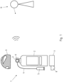
- FIG. 1 shows a remotely monitored handheld fire extinguisher according to the invention.
- This handheld fire extinguisher has a container 2 containing a fire extinguishing medium (not shown in detail).
- a handle 3 is arranged on the upper side to allow the fire extinguisher to be carried and also to be triggered using the handle 3.
- a hose 4 extends from the handle 3 itself.
- An outlet nozzle 5 is arranged at the end of the hose 4, so that, if necessary, fire extinguishing medium can be directed via the outlet nozzle 5 onto the source of the fire. can be.
- a remote monitoring module 6 is now arranged in the area of the handle 3. This measures the temperature and pressure of the fire extinguishing medium within the container 2.
- a lower base pan is also shown.
- a plug contact 8 is arranged on the lower base pan.
- the outlet nozzle 5 is arranged in this plug contact 8 when assembled. This makes it possible to detect actuation or removal of the outlet nozzle 5, so that use or at least sabotage of the fire extinguisher can be assumed.
- a hood 9 which is arranged over the upper area of the fire extinguisher.
- a remote communication module in particular a GSM module, is also arranged in the remote monitoring module 6, which wirelessly transmits a signal 10, in particular via a mobile radio standard, to a receiving station 11 (not shown in detail).
- Receiving station 11 may, for example, be a company that maintains and tests fire extinguishers.
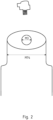
- Figure 2 shows an adapter disc.
- An opening 12 of the container 2 can thus be reduced from a larger diameter 13 to a smaller diameter 13.
- existing containers 2 can also be retrofitted with the solution according to the invention, since the remote monitoring module 6 is preferably present in the area of the handle 3, thus with a screw thread.
- various existing fire extinguishers can also be retrofitted.
- the remotely monitored handheld fire extinguisher has a remote monitoring module 6. This sends data about the status and operational capability to a receiving station 11. This data can then be read by a certified body and verified according to the relevant standards and/or laws or requirements. If the remotely monitored fire extinguisher meets all requirements and is ready for use, the certified body 14 can transmit a certificate 15 with a digital signature. This can then be stored optionally or additionally, for example, in a cloud 16. It can also be printed out and attached directly to the fire extinguisher. for example, in the form of an adhesive label or similar. However, it can also be stored, for example, in an office building or with a corresponding safety or fire protection officer.
- the fire extinguisher can also have a barcode or barcode 17, for example.
- the certificate 15 is then renewed for the barcode or barcode 17 in a database or cloud 16.
- a fire protection officer or a statutory occupational health and safety monitoring authority can then inquire about the current test status of the fire extinguisher by reading the barcode or barcode 17. This offers the option of eliminating the need for a test technician to visit a locally stationed hand-held fire extinguisher at specified intervals, subjecting it to a visual and/or technical inspection and then certifying its operational readiness with an analog seal. This saves both travel and on-site testing thanks to the combination of remote monitoring and a certificate 15 with a digital signature. This saves resources and labor, and protects the environment.
Landscapes
- Health & Medical Sciences (AREA)
- Public Health (AREA)
- Business, Economics & Management (AREA)
- Emergency Management (AREA)
- Fire-Extinguishing By Fire Departments, And Fire-Extinguishing Equipment And Control Thereof (AREA)
Priority Applications (8)
| Application Number | Priority Date | Filing Date | Title |
|---|---|---|---|
| EP23182757.7A EP4483971B1 (de) | 2023-06-30 | 2023-06-30 | Verfahren zum betreiben eines fernüberwachten handfeuerlöschers |
| HUE23182757A HUE072930T2 (hu) | 2023-06-30 | 2023-06-30 | Eljárás távfelügyelt kézi tûzoltó készülék üzemeltetésére |
| HRP20251063TT HRP20251063T1 (hr) | 2023-06-30 | 2023-06-30 | Postupak za upravljanje daljinski nadziranim ručnim vatrogasnim aparatom |
| PL23182757.7T PL4483971T3 (pl) | 2023-06-30 | 2023-06-30 | Sposób obsługi zdalnie monitorowanej gaśnicy ręcznej |
| ES23182757T ES3039183T3 (en) | 2023-06-30 | 2023-06-30 | Method for operating a remotely monitored hand fire extinguisher |
| PCT/EP2024/068377 WO2025003479A1 (de) | 2023-06-30 | 2024-06-28 | Verfahren zum betreiben eines fernüberwachten handfeuerlöschers |
| AU2024309611A AU2024309611A1 (en) | 2023-06-30 | 2024-06-28 | Method for operating a remote-controlled portable fire extinguisher |
| IL325354A IL325354A (en) | 2023-06-30 | 2025-12-15 | Method for operating a remote-controlled portable fire extinguisher |
Applications Claiming Priority (1)
| Application Number | Priority Date | Filing Date | Title |
|---|---|---|---|
| EP23182757.7A EP4483971B1 (de) | 2023-06-30 | 2023-06-30 | Verfahren zum betreiben eines fernüberwachten handfeuerlöschers |
Publications (3)
| Publication Number | Publication Date |
|---|---|
| EP4483971A1 EP4483971A1 (de) | 2025-01-01 |
| EP4483971B1 true EP4483971B1 (de) | 2025-06-25 |
| EP4483971C0 EP4483971C0 (de) | 2025-06-25 |
Family
ID=87060364
Family Applications (1)
| Application Number | Title | Priority Date | Filing Date |
|---|---|---|---|
| EP23182757.7A Active EP4483971B1 (de) | 2023-06-30 | 2023-06-30 | Verfahren zum betreiben eines fernüberwachten handfeuerlöschers |
Country Status (5)
| Country | Link |
|---|---|
| EP (1) | EP4483971B1 (pl) |
| ES (1) | ES3039183T3 (pl) |
| HR (1) | HRP20251063T1 (pl) |
| HU (1) | HUE072930T2 (pl) |
| PL (1) | PL4483971T3 (pl) |
Citations (1)
| Publication number | Priority date | Publication date | Assignee | Title |
|---|---|---|---|---|
| US20220193472A1 (en) * | 2019-09-12 | 2022-06-23 | Carrier Corporation | A system and method for guiding a user operating a fire extinguisher |
Family Cites Families (5)
| Publication number | Priority date | Publication date | Assignee | Title |
|---|---|---|---|---|
| ITTO20080643A1 (it) * | 2008-08-25 | 2010-02-26 | Sabatino Pompa | Apparato di segnalazione di posizione di estintori |
| HUE034400T2 (en) * | 2012-12-28 | 2018-02-28 | Bp S R L S | Equipment for remote control of fire extinguishers and / or fire hydrants |
| CN105701525A (zh) * | 2016-04-06 | 2016-06-22 | 上海动联信息技术股份有限公司 | 一种灭火器的生命周期感知与管理系统及方法 |
| KR20190122321A (ko) * | 2018-04-20 | 2019-10-30 | 진영배 | 소화기 정보 관리시스템 및 관리방법 |
| GB2576151B (en) * | 2018-08-06 | 2021-09-08 | Lehavot Production & Prot 1995 Ltd | Retrofit fire extinguisher apparatus |
-
2023
- 2023-06-30 EP EP23182757.7A patent/EP4483971B1/de active Active
- 2023-06-30 ES ES23182757T patent/ES3039183T3/es active Active
- 2023-06-30 HR HRP20251063TT patent/HRP20251063T1/hr unknown
- 2023-06-30 PL PL23182757.7T patent/PL4483971T3/pl unknown
- 2023-06-30 HU HUE23182757A patent/HUE072930T2/hu unknown
Patent Citations (1)
| Publication number | Priority date | Publication date | Assignee | Title |
|---|---|---|---|---|
| US20220193472A1 (en) * | 2019-09-12 | 2022-06-23 | Carrier Corporation | A system and method for guiding a user operating a fire extinguisher |
Also Published As
| Publication number | Publication date |
|---|---|
| PL4483971T3 (pl) | 2025-12-22 |
| ES3039183T3 (en) | 2025-10-17 |
| EP4483971C0 (de) | 2025-06-25 |
| HUE072930T2 (hu) | 2025-12-28 |
| EP4483971A1 (de) | 2025-01-01 |
| HRP20251063T1 (hr) | 2025-12-19 |
Similar Documents
| Publication | Publication Date | Title |
|---|---|---|
| DE102006045404B4 (de) | Telematikverfahren und -system | |
| DE202008005467U1 (de) | Positionsüberwachungseinrichtung für Personen | |
| EP3109835B1 (de) | Verfahren und system zur fahr- und fahrerdatenerfassung | |
| EP4483971B1 (de) | Verfahren zum betreiben eines fernüberwachten handfeuerlöschers | |
| DE102023117359B3 (de) | Fernüberwachter Handfeuerlöscher sowie Verfahren zum Betreiben | |
| DE102011012495B4 (de) | Verfahren zur Kontrolle der Durchführung von Wartungsarbeiten an Brandlöschanlagen | |
| WO2025003479A1 (de) | Verfahren zum betreiben eines fernüberwachten handfeuerlöschers | |
| DE102023005465A1 (de) | Fernüberwachter Handfeuerlöscher sowie Verfahren zum Betreiben | |
| DE102019125087A1 (de) | Vorrichtung und Verfahren zur Identifikation und Zustandsüberwachung einer zu überwachenden Einrichtung mit einem öffenbaren und verschließbaren Flügelelement | |
| DE102012009491A1 (de) | Codebasierte Absicherung eines Schließ- oder Öffnungsvorgangs von Fahrzeugen mit Funkschlüsseln | |
| DE102010020941A1 (de) | Mobiles Datengerät und Verfahren zum Lesen von Daten von einem Datenträger | |
| EP1648768B1 (de) | Sitz mit datenspeicher, insbesondere fluggastsitz, und zugehöriges lesegerät | |
| EP2958064A1 (de) | Verfahren und system zur bereitstellung von gefahrgutinformationen | |
| WO2006074861A1 (de) | Einrichtung und verfahren zur registrierung des öffnens von verschlüssen von zu sichernden räumen | |
| EP1891398A1 (de) | Elektronisches gerät zur erfassung, speicherung und verarbeitung von messdaten, insbesondere datenlogger | |
| EP3419304B1 (de) | System und verfahren zum fernüberwachen einer manuell einstellbaren zustandsanzeige einer druckgasflaschenanordnung | |
| DE102017113213A1 (de) | Anordnung zur Zusammenstellung und/oder Bestimmung der Wagenreihung und/oder Überprüfung der Vollständigkeit eines Schienenfahrzeugs, ein Verfahren und dessen Verwendung | |
| DE102016124047B4 (de) | Verfahren zum Schutz von Fahrzeugdaten gegen Manipulationen | |
| DE202018000648U1 (de) | Aufbewahrungseinrichtung für Rettungsmittel, Höhensicherungsgeräte und persönliche Schutzausrüstungen gegen Absturz die mit einem Low Power Wide Area (LPWA) Sensor ausgestattet ist | |
| DE102013109509A1 (de) | Kennzeichnung für Gefahrguttransporte sowie Gerät und Verfahren zur Erkennung der Gefährdung | |
| DE20116268U1 (de) | Anordnung zur berührungslosen Überwachung von Druckgasbehältern | |
| DE102008037192A1 (de) | Überwachungssystem | |
| DE102016117813A1 (de) | Tragbare Vorrichtung zum Diagnostizieren eines prozessfluidführenden Stellgeräts und Verfahren zur Diagnose des Zustands eines prozessfluidführenden Stellgeräts | |
| DE102019125081A1 (de) | Vorrichtung und Verfahren zur Identifikation und Zustandsüberwachung einer zu überwachenden Einrichtung | |
| EP2731085A1 (de) | Telekommunikationsendgerät, System und Verfahren zur Unterstützung der Wartung und/oder der Reparatur von Fahrzeugen, Computerprogramm und Computerprogrammprodukt |
Legal Events
| Date | Code | Title | Description |
|---|---|---|---|
| REG | Reference to a national code |
Ref country code: HR Ref legal event code: TUEP Ref document number: P20251063T Country of ref document: HR |
|
| STAA | Information on the status of an ep patent application or granted ep patent |
Free format text: STATUS: EXAMINATION IS IN PROGRESS |
|
| PUAI | Public reference made under article 153(3) epc to a published international application that has entered the european phase |
Free format text: ORIGINAL CODE: 0009012 |
|
| 17P | Request for examination filed |
Effective date: 20240112 |
|
| AK | Designated contracting states |
Kind code of ref document: A1 Designated state(s): AL AT BE BG CH CY CZ DE DK EE ES FI FR GB GR HR HU IE IS IT LI LT LU LV MC ME MK MT NL NO PL PT RO RS SE SI SK SM TR |
|
| GRAP | Despatch of communication of intention to grant a patent |
Free format text: ORIGINAL CODE: EPIDOSNIGR1 |
|
| STAA | Information on the status of an ep patent application or granted ep patent |
Free format text: STATUS: GRANT OF PATENT IS INTENDED |
|
| INTG | Intention to grant announced |
Effective date: 20250117 |
|
| GRAS | Grant fee paid |
Free format text: ORIGINAL CODE: EPIDOSNIGR3 |
|
| GRAA | (expected) grant |
Free format text: ORIGINAL CODE: 0009210 |
|
| STAA | Information on the status of an ep patent application or granted ep patent |
Free format text: STATUS: THE PATENT HAS BEEN GRANTED |
|
| AK | Designated contracting states |
Kind code of ref document: B1 Designated state(s): AL AT BE BG CH CY CZ DE DK EE ES FI FR GB GR HR HU IE IS IT LI LT LU LV MC ME MK MT NL NO PL PT RO RS SE SI SK SM TR |
|
| REG | Reference to a national code |
Ref country code: GB Ref legal event code: FG4D Free format text: NOT ENGLISH |
|
| REG | Reference to a national code |
Ref country code: CH Ref legal event code: EP |
|
| REG | Reference to a national code |
Ref country code: DE Ref legal event code: R096 Ref document number: 502023001214 Country of ref document: DE |
|
| REG | Reference to a national code |
Ref country code: CH Ref legal event code: EP |
|
| REG | Reference to a national code |
Ref country code: IE Ref legal event code: FG4D Free format text: LANGUAGE OF EP DOCUMENT: GERMAN |
|
| U01 | Request for unitary effect filed |
Effective date: 20250724 |
|
| U07 | Unitary effect registered |
Designated state(s): AT BE BG DE DK EE FI FR IT LT LU LV MT NL PT RO SE SI Effective date: 20250806 |
|
| U20 | Renewal fee for the european patent with unitary effect paid |
Year of fee payment: 3 Effective date: 20250807 |
|
| PGFP | Annual fee paid to national office [announced via postgrant information from national office to epo] |
Ref country code: ES Payment date: 20250828 Year of fee payment: 3 |
|
| PGFP | Annual fee paid to national office [announced via postgrant information from national office to epo] |
Ref country code: MC Payment date: 20250812 Year of fee payment: 3 Ref country code: NO Payment date: 20250813 Year of fee payment: 3 |
|
| PGFP | Annual fee paid to national office [announced via postgrant information from national office to epo] |
Ref country code: TR Payment date: 20250915 Year of fee payment: 3 |
|
| REG | Reference to a national code |
Ref country code: SK Ref legal event code: T3 Ref document number: E 46966 Country of ref document: SK |
|
| PGFP | Annual fee paid to national office [announced via postgrant information from national office to epo] |
Ref country code: HR Payment date: 20250904 Year of fee payment: 3 |
|
| REG | Reference to a national code |
Ref country code: ES Ref legal event code: FG2A Ref document number: 3039183 Country of ref document: ES Kind code of ref document: T3 Effective date: 20251017 |
|
| PG25 | Lapsed in a contracting state [announced via postgrant information from national office to epo] |
Ref country code: RS Free format text: LAPSE BECAUSE OF FAILURE TO SUBMIT A TRANSLATION OF THE DESCRIPTION OR TO PAY THE FEE WITHIN THE PRESCRIBED TIME-LIMIT Effective date: 20250925 |
|
| PGFP | Annual fee paid to national office [announced via postgrant information from national office to epo] |
Ref country code: IE Payment date: 20250820 Year of fee payment: 3 |
|
| REG | Reference to a national code |
Ref country code: HR Ref legal event code: ODRP Ref document number: P20251063T Country of ref document: HR Payment date: 20250904 Year of fee payment: 3 |
|
| PGFP | Annual fee paid to national office [announced via postgrant information from national office to epo] |
Ref country code: SK Payment date: 20250818 Year of fee payment: 3 |
|
| PGFP | Annual fee paid to national office [announced via postgrant information from national office to epo] |
Ref country code: IS Payment date: 20250812 Year of fee payment: 3 |
|
| REG | Reference to a national code |
Ref country code: GR Ref legal event code: EP Ref document number: 20250401925 Country of ref document: GR Effective date: 20251009 |
|
| PGFP | Annual fee paid to national office [announced via postgrant information from national office to epo] |
Ref country code: HU Payment date: 20250827 Year of fee payment: 3 |
|
| REG | Reference to a national code |
Ref country code: HR Ref legal event code: T1PR Ref document number: P20251063 Country of ref document: HR |
|
| REG | Reference to a national code |
Ref country code: HU Ref legal event code: AG4A Ref document number: E072930 Country of ref document: HU |
|
| PG25 | Lapsed in a contracting state [announced via postgrant information from national office to epo] |
Ref country code: SM Free format text: LAPSE BECAUSE OF FAILURE TO SUBMIT A TRANSLATION OF THE DESCRIPTION OR TO PAY THE FEE WITHIN THE PRESCRIBED TIME-LIMIT Effective date: 20250625 |
|
| PGFP | Annual fee paid to national office [announced via postgrant information from national office to epo] |
Ref country code: GR Payment date: 20251003 Year of fee payment: 3 |
|
| PGFP | Annual fee paid to national office [announced via postgrant information from national office to epo] |
Ref country code: CY Payment date: 20250812 Year of fee payment: 3 Ref country code: CZ Payment date: 20250818 Year of fee payment: 3 |
|
| PGFP | Annual fee paid to national office [announced via postgrant information from national office to epo] |
Ref country code: PL Payment date: 20250812 Year of fee payment: 3 |