EP4483774A1 - Shoe care apparatus - Google Patents
Shoe care apparatus Download PDFInfo
- Publication number
- EP4483774A1 EP4483774A1 EP23860689.1A EP23860689A EP4483774A1 EP 4483774 A1 EP4483774 A1 EP 4483774A1 EP 23860689 A EP23860689 A EP 23860689A EP 4483774 A1 EP4483774 A1 EP 4483774A1
- Authority
- EP
- European Patent Office
- Prior art keywords
- nozzle
- care device
- inner cabinet
- hinge axis
- air
- Prior art date
- Legal status (The legal status is an assumption and is not a legal conclusion. Google has not performed a legal analysis and makes no representation as to the accuracy of the status listed.)
- Pending
Links
Images










Classifications
-
- A—HUMAN NECESSITIES
- A47—FURNITURE; DOMESTIC ARTICLES OR APPLIANCES; COFFEE MILLS; SPICE MILLS; SUCTION CLEANERS IN GENERAL
- A47L—DOMESTIC WASHING OR CLEANING; SUCTION CLEANERS IN GENERAL
- A47L23/00—Cleaning footwear
- A47L23/20—Devices or implements for drying footwear, also with heating arrangements
- A47L23/205—Devices or implements for drying footwear, also with heating arrangements with heating arrangements
-
- A—HUMAN NECESSITIES
- A47—FURNITURE; DOMESTIC ARTICLES OR APPLIANCES; COFFEE MILLS; SPICE MILLS; SUCTION CLEANERS IN GENERAL
- A47L—DOMESTIC WASHING OR CLEANING; SUCTION CLEANERS IN GENERAL
- A47L23/00—Cleaning footwear
- A47L23/20—Devices or implements for drying footwear, also with heating arrangements
-
- A—HUMAN NECESSITIES
- A47—FURNITURE; DOMESTIC ARTICLES OR APPLIANCES; COFFEE MILLS; SPICE MILLS; SUCTION CLEANERS IN GENERAL
- A47B—TABLES; DESKS; OFFICE FURNITURE; CABINETS; DRAWERS; GENERAL DETAILS OF FURNITURE
- A47B61/00—Wardrobes
- A47B61/04—Wardrobes for shoes, hats, umbrellas, or the like
-
- A—HUMAN NECESSITIES
- A47—FURNITURE; DOMESTIC ARTICLES OR APPLIANCES; COFFEE MILLS; SPICE MILLS; SUCTION CLEANERS IN GENERAL
- A47F—SPECIAL FURNITURE, FITTINGS, OR ACCESSORIES FOR SHOPS, STOREHOUSES, BARS, RESTAURANTS OR THE LIKE; PAYING COUNTERS
- A47F3/00—Show cases or show cabinets
- A47F3/001—Devices for lighting, humidifying, heating, ventilation
-
- F—MECHANICAL ENGINEERING; LIGHTING; HEATING; WEAPONS; BLASTING
- F26—DRYING
- F26B—DRYING SOLID MATERIALS OR OBJECTS BY REMOVING LIQUID THEREFROM
- F26B21/00—Arrangements for supplying or controlling air or other gases for drying solid materials or objects
- F26B21/50—Ducting arrangements from the source of air or other gases to the materials or objects being dried
-
- F—MECHANICAL ENGINEERING; LIGHTING; HEATING; WEAPONS; BLASTING
- F26—DRYING
- F26B—DRYING SOLID MATERIALS OR OBJECTS BY REMOVING LIQUID THEREFROM
- F26B9/00—Machines or apparatus for drying solid materials or objects at rest or with only local agitation; Domestic airing cupboards
- F26B9/06—Machines or apparatus for drying solid materials or objects at rest or with only local agitation; Domestic airing cupboards in stationary drums or chambers
- F26B9/066—Machines or apparatus for drying solid materials or objects at rest or with only local agitation; Domestic airing cupboards in stationary drums or chambers the products to be dried being disposed on one or more containers, which may have at least partly gas-previous walls, e.g. trays or shelves in a stack
-
- A—HUMAN NECESSITIES
- A61—MEDICAL OR VETERINARY SCIENCE; HYGIENE
- A61L—METHODS OR APPARATUS FOR STERILISING MATERIALS OR OBJECTS IN GENERAL; DISINFECTION, STERILISATION OR DEODORISATION OF AIR; CHEMICAL ASPECTS OF BANDAGES, DRESSINGS, ABSORBENT PADS OR SURGICAL ARTICLES; MATERIALS FOR BANDAGES, DRESSINGS, ABSORBENT PADS OR SURGICAL ARTICLES
- A61L2/00—Disinfection or sterilisation of materials or objects, in general; Accessories therefor
- A61L2/02—Disinfection or sterilisation of materials or objects, in general; Accessories therefor using physical processes
- A61L2/04—Heat
- A61L2/06—Hot gas
-
- A—HUMAN NECESSITIES
- A61—MEDICAL OR VETERINARY SCIENCE; HYGIENE
- A61L—METHODS OR APPARATUS FOR STERILISING MATERIALS OR OBJECTS IN GENERAL; DISINFECTION, STERILISATION OR DEODORISATION OF AIR; CHEMICAL ASPECTS OF BANDAGES, DRESSINGS, ABSORBENT PADS OR SURGICAL ARTICLES; MATERIALS FOR BANDAGES, DRESSINGS, ABSORBENT PADS OR SURGICAL ARTICLES
- A61L2/00—Disinfection or sterilisation of materials or objects, in general; Accessories therefor
- A61L2/02—Disinfection or sterilisation of materials or objects, in general; Accessories therefor using physical processes
- A61L2/04—Heat
- A61L2/06—Hot gas
- A61L2/07—Steam
-
- A—HUMAN NECESSITIES
- A61—MEDICAL OR VETERINARY SCIENCE; HYGIENE
- A61L—METHODS OR APPARATUS FOR STERILISING MATERIALS OR OBJECTS IN GENERAL; DISINFECTION, STERILISATION OR DEODORISATION OF AIR; CHEMICAL ASPECTS OF BANDAGES, DRESSINGS, ABSORBENT PADS OR SURGICAL ARTICLES; MATERIALS FOR BANDAGES, DRESSINGS, ABSORBENT PADS OR SURGICAL ARTICLES
- A61L2202/00—Aspects relating to methods or apparatus for disinfecting or sterilising materials or objects
- A61L2202/10—Apparatus features
- A61L2202/12—Apparatus for isolating biocidal substances from the environment
- A61L2202/122—Chambers for sterilisation
Definitions
- the present invention relates to a shoes care device, and more particular, to a shoes care device which treats shoes by air circulation.
- Shoes may get wet by a wearer's sweat, external contaminants, or rain or snow. Wearing such shoes may make the wearer uncomfortable, and in the condition, germs may also breed or stink in the shoes.
- a shoes care device 1 which removes germs and odors by performing a predetermined treatment on the shoes so that a user can comfortably wear the shoes all the times.
- Korean Patent No. 1037245 discloses "Apparatus for sterilization disposal of shoes", which includes a main body, an ultraviolet emission module, and a deodorization module.
- the shoes are disposed in a sterilization chamber of the main body, and the ultraviolet emission module is driven to remove germs and odors of the shoes. Furthermore, the air in the sterilization chamber is inhaled into a ventilation pipe and discharged to the outside of the main body through an exhaust port through the deodorization module.
- the deodorization module includes a deodorization column made up of materials such as zeolite, activated carbon, and charcoal, and removes contaminants from the air discharged from the inside of the main body to the outside by the deodorization column.
- a deodorization column made up of materials such as zeolite, activated carbon, and charcoal, and removes contaminants from the air discharged from the inside of the main body to the outside by the deodorization column.
- the air from which moisture has been removed by a deodorization module including zeolite and activated carbon can be discharged to the outside of the apparatus for sterilization disposal of shoes.
- Korean Patent Unexamined Publication No. 10-2000-0009653 discloses "The shoes cabinet for sanitation", which includes a main body, a far infrared radiation part, a circulation fan, an air circulation passage, and a sanitary filter portion.
- the sanitary filter portion is filled with excellent adsorptive materials such as charcoal, it can serve to adsorb moisture in the process of ventilating air and filter bacteria, as well as to capture malodorous substances.
- the air is circulated by a circulating fan in a shoe closet, and the sanitary filter portion is disposed on a circulation path of the air to remove germs and odors in the air.
- Prior Document 2 above does not consider a technology to prevent the reduction of the performance of the sanitary filter portion configured to remove moisture or odors, a user may not be satisfied because the shoes are not properly treated at the time of using a shoes care device.
- An object to be achieved by the present invention is to solve the aforementioned problems caused by a shoes care device which treats shoes by air circulation.
- an object to be achieved by the present invention is to provide a shoes care device which can ensure proper performance for shoes treatment at all times by performing dehumidification and deodorization on the shoes using a dehumidifying material to refresh the shoes and regenerating the used dehumidifying material.
- An object to be achieved by the present invention is to provide a shoes care device which prevents air used for dehumidification and deodorization of shoes from being exposed to a user by an air circulation structure capable of dehumidifying the air inside an inner cabinet where the shoes are placed by using a dehumidifying material and supplying the dehumidified air again to the inner cabinet.
- An object to be achieved by the present invention is to provide a shoe care device in which a nozzle duct, which supplies air into the inner cabinet, is installed stably to prevent functional deterioration or inconvenience in use due to structural deformation or the like due to use.
- a shoes care device configured not only to perform dehumidification and deodorization of shoes using a dehumidifying part but also to regenerate the used dehumidifying part.
- the shoes care device is configured not only to collect moisture and bacteria in air ventilated by the dehumidifying part in a module chamber but also to heat and regenerate the dehumidifying part in the module chamber.
- the shoes care device is configured such that the air used for dehumidifying and deodorizing the shoes has an air circulation structure inside the shoes care device. Specifically, a connection path through which air is circulated is formed between a outlet and a nozzle disposed inside an inner cabinet, respectively.
- the shoe care device is configured such that a nozzle duct, which serves as an air passage for dehumidifying and deodorizing shoes, has sufficient rigidity to stably supply air to the inner cabinet.
- a nozzle rib is provided to connect the upper and lower surfaces inside the tubular nozzle bar so as to reinforce rigidity.
- the shoe care device may perform steam treatment on shoes by supplying steam into the inner cabinet.
- the shoe care device may have a nozzle duct installed to face the front side from the rear wall of the inner cabinet.
- the nozzle duct may be coupled to the inner cabinet in a penetration structure.
- the nozzle duct may be sealed at a coupling surface other than the portion where the nozzle duct penetrates the inner cabinet, by a nozzle sealing part.
- the nozzle sealing part which is in contact with the outer peripheral surface of the nozzle bar, may be relatively thin.
- the nozzle duct may be supported with respect to the inner cabinet by a nozzle supporter.
- a nozzle supporter hook provided on the nozzle supporter may be fastened to the outer peripheral surface of the nozzle bar.
- the shoe care device may have a nozzle supporter rib provided on the inner surface of the nozzle supporter along the longitudinal direction of the nozzle bar.
- the nozzle supporter may be supported on the inner cabinet by a hinge axis resistance part by being hinged to the inner cabinet via a nozzle supporter hinge axis.
- the hinge axis resistance part may generate a frictional force on the nozzle supporter hinge axis.
- a pair of nozzle supporter hinge axes may be installed on opposite side surfaces of the nozzle supporter.
- the hinge axis resistance part may include a first hinge axis holder and a second hinge axis holder.
- a hinge axis holder hook provided on the second hinge axis holder may be fastened to a hinge axis holder groove provided in the first hinge axis holder.
- one end and the other end of the nozzle duct may be hinged to the inner cabinet and the nozzle, respectively, and separately from the nozzle duct, one end and the other end of the nozzle connector are hinged to the inner cabinet and the nozzle, respectively.
- the upper surface of the nozzle connector may be engaged with a nozzle supporter groove provided in the lower surface of the nozzle supporter.
- a first direction (X direction), a second direction (Y direction), and a third direction (Z direction) described in one embodiment of the present invention may be directions orthogonal to each other.
- Each of the first direction (X direction) and the second direction (Y direction) may be a direction parallel to the horizontal direction, and the third direction (Z direction) may be a direction parallel to the vertical direction.
- the second direction (Y direction) may be parallel to a front-rear direction.
- the second direction (Y direction) may be parallel to the left-right direction.
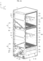
- FIG. 1a is a perspective view illustrating a shoes care device according to one embodiment of the present invention.
- FIG. 1b is a perspective view of the shoes care device of FIG. 1a , when viewed from another direction, illustrating a state in which a door is opened.
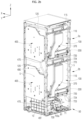
- FIG. 2a is a perspective view illustrating a state in which a part of the door and an outer cabinet are removed from the shoes care device of FIG. 1b .
- FIG. 2b is a perspective view illustrating a state in which the shoes care device illustrated in FIG. 2a is viewed from another direction.
- a shoes care device 1 may include an outer cabinet 20, a door 30, an inner cabinet 100, and a machine room 50.
- the shoes care device 1 may include a main frame 5.
- the outer cabinet 20 and the door 30 may form an overall appearance of the shoes care device 1.
- the outside of the shoes care device 1 may be formed in a hexahedral shape. That is, while the outer cabinet 20 and the door 30 are coupled to each other and the door 30 is closed, the appearance of the shoes care device 1 may be formed in a hexahedral shape.
- the shoes care device 1 according to one embodiment of the present invention is not limited to such a shape and may have various three-dimensional shapes.
- the outer cabinet 20 may form an upper side surface, a left-side surface, a right-side surface, a rear surface, and bottom surfaces of the shoes care device 1.
- the main frame 5 may form an overall framework of the shoes care device 1.
- the main frame 5 may have a hexahedral structure.
- the outer cabinet 20 may be detachably fixed to the main frame 5.
- the outer cabinet 20 may include an outer rear plate 21, a first outer side plate 22, and a second outer side plate 23.
- the outer back plate 21, the first outer side plate 22, and the second outer side plate 23 may be formed integrally with each other, or the outer back plate 21, the first outer side plate 22, and the second outer side plate 23 may be individually formed.
- the outer rear plate 21 forms a vertically erected wall surface.
- the outer rear plate 21 may form a surface orthogonal to the first direction (X direction).
- the outer rear plate 21 may form a rear wall surface in the first direction (X direction) on the outer cabinet 20.
- the outer rear plate 21 may form a rear surface in the first direction (X direction) in the shoes care device 1.
- the outer rear plate 21 may form an entire outer rear surface of the shoes care device 1.
- the first outer side plate 22 and the second outer side plate 23 form vertically erected wall surfaces, respectively, and form opposing wall surfaces facing each other.
- the first outer side plate 22 is disposed at any one side with respect to a reference plane RP that is parallel to the first direction (X direction) as a horizontal direction and is a vertical plane.
- the second outer side plate 23 is disposed on the opposite side of the first outer side plate 22 with respect to the reference plane RP.
- the first outer side plate 22 may form a left wall surface of the outer cabinet 20, and the second outer side plate 23 may form a right wall surface of the outer cabinet 20.
- the outer cabinet 20 may be disposed outside the inner cabinet 100 and the machine room 50 to form an outer wall surface of the machine room 50.
- the outer cabinet 20 may form a wall separating the machine room 50 from the outside.
- the door 30 is configured to open and close the inside of the shoes care device 1.
- the door 30 may form any one surface of the shoes care device 1.
- the door 30 may form a left side or a right side of the shoes care device 1, or may form a front side of the shoes care device 1.
- the door 30 may be hinge-coupled.
- the door 30 may be hinge-coupled to the main frame 5. In another embodiment, the door 30 may be hinge-coupled to the outer cabinet 20, and in another embodiment, the door 30 may be hinge-coupled to the inner cabinet 100 and/or the machine room 50.
- a hinge rotation axis 31 of the door 30 may be formed in the vertical direction. That is, in the shoes care device 1, the door 30 may be configured to be rotatable bidirectionally around a rotation axis 31 in the vertical direction.
- the shoes care device 1 may include one door 30. In another embodiment, the shoes care device 1 may include two or more doors.
- each door may be individually rotated around each rotation axis.
- the first direction (X direction) described in one embodiment of the present invention may be parallel to or substantially parallel to the horizontal direction.
- the first direction (X direction) may be a direction from the rear of the shoes care device 1 to the front.
- the door 30 is formed in a front side of the shoes care device 1. That is, a surface on which the door 30 is formed in the shoes care device 1 is described as a front surface of the shoes care device 1.
- first direction is parallel to the front-rear direction
- second direction is parallel to the left-right direction
- third direction is parallel to the vertical direction.
- the inner cabinet 100 and the machine room 50 may be provided inside the outer cabinet 20.
- the inner cabinet 100 may be formed in a box shape, and a predetermined space may be formed therein.
- the space inside the inner cabinet 100 forms an accommodation space 101, and shoes S may be accommodated in the accommodation space 101.
- a plurality of shoes S may be disposed together in the accommodation space 101 of one inner cabinet 100.
- the inner cabinet 100 may be fixed to the main frame 5.
- the inner cabinet 100 has a predetermined size along the first direction (X direction), the second direction (Y direction), and the third direction (Z direction).
- the inner cabinet 100 is formed in the shape of a box opened to any one side.
- the inner cabinet 100 may be formed in a form opened to the front side of the shoes care device 1.
- the inner cabinet 100 may be configured to include a main opening 140.
- the main opening 140 may be provided to open the front side of the inner cabinet 100 in the first direction (X direction).
- the shoes may be disposed inside the inner cabinet 100 or withdrawn from the inner cabinet 100 through the main opening 140.
- the main opening 140 of the inner cabinet 100 may be closed or opened by the door 30.
- the inner cabinet 100 may include an inner rear plate 110, a first inner side plate 120, a second inner side plate 130, and an inner upper plate 115.
- the inner rear plate 110, the first inner side plate 120, the second inner side plate 130, and the inner upper plate 115 may be formed integrally with each other.
- the inner cabinet 100 may be made of a single material and be formed by injection molding.
- the inner rear plate 110 forms a vertically erected wall surface.
- the inner rear plate 110 may form a surface orthogonal to the first direction (X direction).
- the inner rear plate 110 may form a rear wall surface of the inner cabinet 100 in the first direction (X direction).
- the inner rear plate 110 may be formed parallel to the outer rear plate 21.
- the first inner side plate 120 and the second inner side plate 130 form vertically erected wall surfaces, respectively, and form opposing wall surfaces facing each other.
- the first inner side plate 120 is dispose on either side with respect to the reference plane RP that is parallel to the first direction (X direction) as the horizontal direction and is a vertical surface.
- the second inner side plate 130 is disposed on the opposite side of the first inner side plate 120 with respect to the reference plane RP.
- the first inner side plate 120 forms a left wall surface of the inner cabinet 100
- the second inner side plate 130 forms a right wall surface of the inner cabinet 100.
- the first inner side plate 120 may be formed parallel to the first outer side plate 22, and the second inner side plate 130 may be formed parallel to the second outer side plate 23.
- the inner cabinet 100 may have the form where a lower part thereof is opened. Accordingly, the inner cabinet 100 includes a lower opening 150 formed by opening the lower part thereof. When the inner cabinet 100 is formed in a hexahedral shape on the whole, the lower opening 150 may be formed large to form all or most of a lower surface of the inner cabinet 100 (see FIGS. 53 and 54).
- the shoes care device 1 is not used in a state in which an entire lower part of the inner cabinet 100 is opened, but is used in a state in which the inner cabinet 100 and a module housing 200 are coupled to each other so that the lower opening 150 of the inner cabinet 100 is shielded by the module housing 200. That is, the shoes care device 1 is used so that an upper surface of the module housing 200 forms a bottom surface of the accommodation space 101 of the inner cabinet 100. A further explanation thereof will be described below.
- a main shelf 40 may be provided in the inside 101 of the inner cabinet 100.
- the main shelf 40 may be formed such that the shoes S are settled on an upper surface thereof.
- the main shelf 40 may be formed in the form of a plate with a predetermined area, or may be formed in the form of a grill where multiple bars are spaced apart from each other.
- One main shelf 40 may be provided, or a plurality of main shelves 40 may be provided.
- the main shelf 40 may have a substantially flat plate shape and be disposed on a bottom surface of the inner cabinet 100.
- the main shelf 40 is settled on an upper side of a module cover 202 of the inner cabinet 100.
- the main shelf 40 may be disposed on the upper side of the module cover 202 of the inner cabinet 100 in a stacked form.
- the main shelf 40 is detachable from the inner cabinet 100, and when the main shelf 40 is withdrawn from the inner cabinet 100, the upper surface of the module housing 200 is exposed.
- the main shelf 40 may have a rectangular shape when viewed in a plan view.
- the size of the main shelf 40 may be a size corresponding to the bottom of the accommodation space 101 of the inner cabinet 100. That is, when the main shelf 40 is disposed inside the inner cabinet 100, the main shelf 40 may form all or most of the bottom of the accommodation space 101 of the inner cabinet 100.
- the machine room 50 may be provided in a lower side of the inner cabinet 100.
- some of the components that constitutes the shoes care device 1 may be accommodated, and, in this case, the components that are accommodated in the machine room 50 may be fixed to a main frame 5 or to the inner cabinet 100 or the outer cabinet 20.
- FIG. 3 is a front view illustrating a state in which a door is removed from the shoes care device illustrated in FIG. 1b .
- FIG. 3 illustrates shoes accommodated in an inner cabinet together.
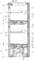
- FIG. 4a is a cross-sectional view taken along line A-A' of the shoes care device illustrated in FIG. 3
- FIG. 4b is a cross-sectional view taken along line B-B' of the shoes care device illustrated in FIG. 3
- FIG. 4c is a cross-sectional view taken along line C-C' of the shoes care device illustrated in FIG. 3
- FIGS. 4a to 4c illustrate a form where a door is included in the shoes care device, and do not illustrate shoes.
- the shoes care device 1 includes management devices 2a and 2b.
- a plurality of management devices 2a and 2b may be provided.
- the shoes care device 1 may include a first management device 2a and a second management device 2b. That is, the shoes care device 1 may include two separate management devices 2a and 2b.
- the 'management device' described in the present invention may refer to a 'first management device 2a' and a 'second management device 2b', respectively, except for a particularly limited case.
- the management devices 2a and 2b include the above-described inner cabinet 100.
- the inner cabinet 100 of the first management device 2a and the inner cabinet 100 of the second management device 2b may be distinguished from each other, the inner cabinet 100a of the first management device 2a may refer to a first inner cabinet 100a, and inner cabinet 100a of the second management device 100b may refer to a second inner cabinet 100b.
- the 'inner cabinet 100' described in one embodiment of the present invention refers to each of the 'first inner cabinet 100a' and the 'second inner cabinet 100b', except for a particularly limited case.
- the door 30 closes the main opening 140 of the first management device 2a and also closes the main opening 140 of the second management device 2b. That is, the door 30 may simultaneously seal the accommodation space 101 of the inner cabinet 100 of the first management device 2a and the accommodation space 101 of the inner cabinet 100 of the second management device 2b.
- the accommodation space 101 of the inner cabinet 100 of the first management device 2a and the accommodation space 101 of the inner cabinet 100 of the second management device 2b may be configured such that they do not communicate with each other.
- the accommodation space 101 of the inner cabinet 100 of the first management device 2a and the accommodation space 101 of the inner cabinet 100 of the second management device 2b may form independent spaces, and may form blocked spaces (not communicating with each other). Accordingly, the temperature and humidity of the accommodation space 101 of the first management device 2a and the temperature and humidity of the accommodation space 101 of the second management device 2b may be controlled differently from each other.
- the management devices 2a and 2b may be configured to include a connection path F10.
- the management devices 2a and 2b may be configured to include a blowing part 310 and a dehumidifying part 330.
- the management devices 2a and 2b may include a outlet 203 and a nozzle 820.
- the management devices 2a and 2b may include the module housing 200 forming a connection path F10.
- the management devices 2a and 2b may include a regeneration path F20.
- the management devices 2a and 2b may include a heating part 320.
- the management devices 2a and 2b may include a conversion flow path F10a.
- the management devices 2a and 2b may include a damper 350.
- the shoes care device 1 may include a steam generator 700 and a steam valve 710.
- the shoes care device 1 may include a sump 600, a water supply tank 60, and a drain tank 70.
- a predetermined gap may be formed between the inner cabinet 100 and the outer cabinet 20.
- connection path F10 may be provided between the inner cabinet 100 and the outer cabinet 20
- regeneration path F20 may be provided between the inner cabinet 100 and the outer cabinet 20.
- a dry air duct 370 forming the connection path F10 may be provided between the outer rear plate 21 and the inner rear plate 110. Furthermore, a condenser 400 forming the regeneration path F20 may be provided between the outer rear plate 21 and the inner rear plate 110.
- connection path F10 forms a flow path of a fluid.
- connection path F10 forms a passage through which air and/or condensed water inside the shoes care device 1 moves.
- the dehumidifying part 330 is disposed inside the connection path F10 and includes a dehumidifying material.
- the dehumidifying part 330 may be entirely formed of the dehumidifying material, or a part thereof may be formed of the dehumidifying material. A further explanation of the dehumidifying part 330 will be described below.
- the shoes care device 1 has an air circulation structure in which the air inside the inner cabinet 100 in which the shoes are disposed is sucked into the connection path F10 to dehumidify the air using a dehumidifying material 331 and the dehumidified air may be supplied back into the inner cabinet 100.
- connection path F10 may be used as a means to achieve such an air circulation structure in the shoes care device 1. All or part of the connection path F10 may be formed of a pipe, a hose, a tube, a duct, a housing, or a combination thereof.
- the module housing 200 forms part of the connection path F10.
- the outlet 203 is formed in the module housing 200.
- the outlet 203 communicates with the accommodation space 101 of the inner cabinet 100, and forms an inlet of the module housing 200 through which the air of the accommodation space 101 of the inner cabinet 100 is suctioned into the module housing 200.
- the outlet 203 may be disposed below the main shelf 40.
- the main shelf 40 may be formed so as not to block the air in the accommodation space 101 from being sucked into the outlet 203.
- a plurality of holes 45 penetrating in the vertical direction may be formed in the main shelf 40 so as to move the air.
- the inner cabinet 100 and the machine room 50 may form a space separated from each other. Furthermore, the module housing 200 that is part of the management devices 2a and 2b may be provided between the inner cabinet 100 and the machine room 50.
- the inner cabinet 100, the module housing 200, and the machine room 50 are provided inside the shoes care device 1 according to one embodiment of the present invention.
- the inner cabinet 100, the module housing 200, and the machine room 50 may be continuously arranged from the upper side to the lower side.
- the shoes care device 1 includes the first management device 2a and the second management device 2b
- the first management device 2a may be disposed above the second management device 2b. That is, the first management device 2a, the second management device 2b, and the machine room 50 may be continuously arranged from the upper side to the lower side.
- first management device 2a and the second management device 2b include the inner cabinet 100 and the module housing 200, respectively, they may be continuously arranged in an order of the inner cabinet 100 of the first management device 2a, the module housing 200 of the first management device 2a, the inner cabinet 100 of the second management device 2b, the module housing 200 of the second management device 2b, the machine room 50 from the upper side to the lower side.
- the inner cabinet 100 may form a space that mainly accommodates an article (shoes S) to be managed, and the module housing 200 and the machine room 50 may form a space that mainly accommodates components for an operation of the shoes care device 1.
- the blowing part 310, the dehumidifying part 330 (and the dehumidifying material 331), and the heating part 320 may be accommodated inside the module housing 200.
- the machine room 50 may be configured to accommodate a controller 10, the sump 600, the steam generator 700, and the steam valve 710 therein. Furthermore, the machine room 50 may be configured to accommodate the water supply tank 60 and the drain tank 70.
- components not included in the module housing 200 may be fixedly coupled to the inner cabinet 100 and the outside of the module housing 200 or may be fixedly coupled to the main frame 5.
- Components coupled to or accommodated in the machine room 50 may be fixedly coupled to the machine room 50.
- the machine room 50 may include a first wall 51.
- a first wall 51 forms one wall surface of the machine room 50.
- the first wall 51 may be erected in the vertical direction, or may be erected in the substantially vertical direction.
- the first wall 51 may form a wall surface orthogonal to or inclined with the first direction (X direction).
- the first wall 51 may form a front wall surface of the machine room 50, a left wall of the machine room 50, or a right wall of the machine room 50.
- the machine room 50 may include a second wall 52 and a third wall 53.
- the second wall 52 and the third wall 53 form opposite wall surfaces facing each other in the machine room 50.
- the second wall 52 and the third wall 53 may be erected in the vertical direction, or may be erected in the substantially vertical direction.
- the second wall 52 may form a left wall of the machine room 50
- the third wall 53 may form a right wall of the machine room 50.
- the first wall 51 may be formed integrally with the inner cabinet 100, and the second wall 52 and the third wall 53 may be formed integrally with the outer cabinet 20, respectively.
- Each of the water supply tank 60 and the drain tank 70 may be formed in the form of a container for accommodating water.
- the water supply tank 60 may be configured to store water supplied into the shoes care device 1 inside.
- the water supply tank 60 may be configured to store water supplied into the steam generator 700 inside.
- a water pump 61 may be connected to the water supply tank 60.
- the water supply tank 60 for moving water and the first water pump 61 may be connected by a pipe, a hose, etc.
- the drain tank 70 may be configured to store water discharged from the shoes care device 1 inside.
- the drain tank 70 may store water condensed inside the shoes care device 1.
- the drain tank 70 may be configured to store water drained from the sump 600.
- a water pump 71 (a second water pump) may be connected to the drain tank 70.
- the drain pipe 70 for moving water and the second water pump 71 may be connected by a pipe, a hose, etc.
- the water supply tank 60 and the drain tank 70 may be coupled to the machine room 50 to get exposed from the outside of one wall surface of the machine room 50.
- the water supply tank 60 and the drain tank 70 may be disposed in front of the machine room 50.
- the water supply tank 60 and the drain tank 70 may form one wall surface of the machine room 50 along with the first wall 51.
- the water supply tank 60 and the drain tank 70 may be exposed from a front side of the machine room 50, and may be coupled to the machine room 50 to get exposed from the outside of the first wall 51.
- a user may inject water into the water supply tank 60 or discharge water from the drain tank 70.
- the water supply tank 60 and the drain tank 70 may be configured to be detachable from the machine room 50.
- the water supply tank 60 and the drain tank 70 may be detached from the first wall 51.
- a handle 60a of the water supply tank 60 may be formed on an outer surface of the water supply tank 60
- a handle 70a of the drain tank 70 may be formed on an outer surface of the drain tank 70.
- Each of the water supply tank 60 and the drain tank 70 may be configured to be separated from the machine room 50 in an outer direction of the first wall 51.
- the controller 10 may be configured to control operations of each component in connection with each component constituting the shoes care device 1.
- the shoes care device 1 may be provided with a storage medium in which an application program is stored, and the controller 10 may be configured to control the shoes care device 1 by driving an application program according to information input to the shoes care device 1 and information output from the shoes care device 1.
- the controller 10 may control the first management device 2a and the second management device 2b constituting the shoes care device 1 to operate individually.
- the controller 10 may control the first management device 2a and the second management device 2b to operate in different states, and may control shoes (e.g., sneakers) in the first management device 2a and shoes (e.g., heels) in the second management device 2b to be managed under different conditions.
- the controller 10 may control the first management device 2a and the second management device 2b to interwork with each other.
- the door 30 may be disposed on either the inner cabinet 100 or the machine room 50 on the same side as the first wall 51.
- the first wall 51 forms the front surface of the machine room 50, and the door 30 is disposed directly outside the first wall 51.
- the door 30 may be configured to open and close the inner cabinet 100 and further expose or shield the front surface of the machine room 50.
- the door 30 may be configured to expose or shield the inner cabinet 100, the water supply tank 60, and the drain tank 70.
- the door 30, the water supply tank 60, and the drain tank 70 are formed on the same side, and when the door 30 is opened, the water supply tank 60 and the drain tank 70 may be exposed and separated from the shoes care device 1.
- the door 30 may be opened on a front side of the shoes care device 1, and the water supply tank 60 and the drain tank 70 can be separated from or coupled again to the shoes care device 1.
- a control panel 33 for controlling the shoes care device 1 is provided on an outer side of the door 30.
- the control panel 33 may be formed of a touch screen.
- a control unit (controller 10) is provided in the inner space of the door 30 to control each component of the shoes care device 1 in connection with the control panel 33.
- the controller 10 may be provided inside the machine room 50.
- the door 30 may be configured to simultaneously expose or shield the inner cabinet 100 and the machine room 50.
- the door 30 may be configured to open and close only the inner cabinet 100.
- the machine room 50 may not be shielded by the door 30.
- the shoes care device 1 according to one embodiment of the present invention may be further provided with a dedicated door of the machine room 50 to open and close the machine room 50 separately from the door 30.
- FIG. 5 is a perspective view illustrating a state in which the door 30, the outer cabinet 20, and the inner cabinet 100 are removed from the shoes care device 1 according to one embodiment of the present invention.
- FIG. 6 is a perspective view illustrating a machine room part of the shoes care device 1 illustrated in FIG. 5 .
- FIG. 7a is a view illustrating the steam valve 710 according to one embodiment of the present invention, and illustrating a connection relationship considering the movement of steam.
- FIG. 7b is an exploded perspective view illustrating the steam valve illustrated in FIG. 7a .
- the shoes care device 1 is provided with the steam generator 700 as a device configured so as to generate moisture inside the inner cabinet 100.
- the steam generator 700 may be provided inside the machine room 50.
- the steam generator 700 is configured to generate steam and selectively supply moisture and steam to the inside of the inner cabinet 100.
- the shoes care device 1 according to one embodiment may be provided with one steam generator 700, and the shoes care device 1 according to another embodiment may be provided with two or more steam generators 700.
- the steam generator 700 may be configured to supply steam into the inner cabinet 100 of the first management device 2a and/or into the inner cabinet 100 of the second management device 2b.
- one steam generator 700 may be provided with two or more steam generators 700, one of the steam generators 700 may supply steam to the inner cabinet 100 of the first management device 2a, and the other steam generator 700 may supply steam to the inner cabinet 100 of the second management device 2b.
- Moist air formed by the steam generator 700 ('air' described in one embodiment of the present invention may be 'air including moisture') is supplied toward the accommodation space 101 of the inner cabinet 100, and moisture may be circulated in the accommodation space 101 of the inner cabinet 100, and accordingly, the moisture may be supplied to the shoes S.
- the shoes care device 1 may be a refresher device that refreshes the shoes.
- refreshing may refer to a process of removing contaminants, deodorizing, sanitizing, preventing static electricity, or warming by supplying air, heated air, water, mist, steam, etc. to the shoes.
- the steam generator 700 may supply steam to the accommodation space 101 of the inner cabinet 100 in which the shoes S are accommodated, and may perform steam treatment on the shoes, which is further meant to exert a refreshing effect due to swelling of shoes materials as well as sterilization by high-temperature steam.
- the steam generator 700 is provided with a separate heater 700a that heats an inner space and water in the inner space and is configured to heat water to generate steam and supply the heated water to the accommodation space 101 of the inner cabinet 100.
- An external faucet, etc., as a water supply source for supplying water to the steam generator 700, may be used, or a container-type water supply tank provided on one side of the machine room 50 may be used.
- the steam generator 700 may generate steam by receiving water from the water supply tank 60.
- the water supply tank 60 for the movement of water and the steam generator 700 may be connected by a pipe, a hose, etc.
- the steam generator 700 for the movement of steam and the inner cabinet 100 may be connected by a pipe, a hose, etc.
- the steam generated by the steam generator 700 may be supplied into the inner cabinet 100 after passing through the steam valve 710 and a steam separator 720.
- the steam generator 700 and the steam valve 710 may be connected by a pipe, a hose, etc.
- the steam valve 710 and the steam separator 720 may also be connected by a pipe, a hose, etc.
- the steam valve 710 may be disposed adjacent to the steam generator 700, and the steam valve 710 may be provided in the machine room 50.
- the steam generator 700 and the steam valve 710 may be provided below the second management device 2b.
- the steam valve 710 is configured to selectively communicate with each of the accommodation space 101 of the first management device 2a and the accommodation space 101 of the second management device 2b, respectively.
- the steam valve 710 When the steam of the steam generator 700 is supplied to the accommodation space 101 of the first management device 2a and/or the accommodation space 101 of the second management device 2b, the steam valve 710 operates to control whether the stream is supplied or not, and an operation of the stream 710 is driven by the controller 10.
- the steam valve 710 includes a valve housing 711, a valve inlet 712, a first valve outlet 713, a second valve outlet 714, a valve disk 715, and a valve motor 716.
- valve inlet 712 the first valve outlet 713, and the second valve outlet 714 may be blocked by a stopper and deactivated.
- the valve housing 711 forms a body of the steam valve 710, and has a predetermined inner space formed inside.
- the valve inlet 712 may have a tubular shape and be coupled to the valve housing 711 to communicate with the inner space of the valve housing 711.
- the valve inlet 712 is a part connected to the steam generator 700, and steam may flow into the steam valve 710 (inside the valve housing 711) through the valve inlet 712.
- the first valve outlet 713 and the second valve outlet 714 may be formed in a tubular shape and be coupled to the valve housing 711 to communicate with the inner space of the valve housing 711.
- the first valve outlet 713 and the second valve outlet 714 are outlets through which steam is discharged from the steam valve 710.
- the first valve outlet 713 is connected to the accommodation space 101 of the first management device 2a
- the second valve outlet 714 is connected to the accommodation space 101 of the second management device 2b.
- the valve disk 715 is provided inside the steam valve 710 (inside the valve housing 711) and is configured to open and close a flow path inside the steam valve 710.
- the valve disk 715 may be configured to selectively open and close a flow path of the first valve outlet 713 and a flow path of the second valve outlet 714.
- the valve disk 715 is disposed between the valve inlet 712 and the first valve outlet 713, or between the valve inlet 712 and the second valve outlet 714, inside the valve housing 711.
- the valve disk 715 allows the valve inlet 712 and the first valve outlet 713 to communicate with each other or block the communication therewith, and also allows the valve inlet 712 and the second valve outlet 714 to communicate with each other or block the communication therewith.
- the valve disk 715 may be formed in a circular plate shape and may include a valve hole 715a.
- the valve hole 715a is a hole penetrating the valve disk 715.
- the valve disk 715 may be rotatably coupled to the valve housing 711 around a valve rotation axis 715b, and the valve hole 715a may be formed eccentrically from the valve rotation axis 715b.
- the valve motor 716 is coupled to the valve housing 711, and the valve motor 716 is coupled to the rotation axis 715b of the valve disk 715 to rotate the valve disk 715.
- the controller 10 may control the steam valve 710 by controlling an operation of the valve motor 716.
- valve disk 715 rotates by the operation of the valve motor 716, and the valve disk 715 opens or closes a flow path inside the steam valve 710 (inside the valve housing 711) depending on the degree of rotation of the valve disk 715.
- valve inlet 712 and the second valve outlet 714 are blocked from communicating with each other by the valve disk 715, or when the valve inlet 712 and the second valve outlet 714 communicate with each other through the valve hole 715a, the valve outlet 712 and the first valve outlet 713 may be blocked from communicating with each other by the valve disk 715.
- valve inlet 712 may communicate with both the first valve outlet 713 and the second valve outlet 714, or the valve inlet 712 may be blocked from communicating with both the first valve outlet 713 and the second valve outlet 714.
- the valve disk 715 may close a flow path of the second valve outlet 714 while opening a flow path of the first valve outlet 713, and may also close the flow path of the first valve outlet 713 and open the flow path of the second valve outlet 714.
- the steam valve 710 made as described above may operate such that only the valve inlet 712 and the first valve outlet 713 communicate with each other, or only the valve inlet 712 and the second valve outlet 714 communicate with each other.
- all the steam generated by the steam generator 700 may be supplied to the accommodation space 101 of the first management device 2a, or may be supplied to the accommodation space 101 of the second management device 2b.
- the steam generated by the steam generator 700 may be supplied to the accommodation space 101 of the first management device 2a or the accommodation space 101 of the second management device 2b without a pressure drop, and even when only one steam generator 700 is provided in the shoes care device 1, the steam may be sufficiently and stably supplied to the accommodation spaces 101 of each of the two inner cabinets 100.
- the controller 10 may control the stream valve 710 such that when the heating part 320 of the first management device 2a is turned off (when a heater 321 of the heating part 320 is turned off), the valve disk 715 closes or opens the first valve outlet 713, and when the heating part 320 of the first management device 2a is turned on (when the heater 321 of the heating part 320 is turned on), the valve disk 715 closes the first valve outlet 713.
- the controller 10 may control the stream valve 170 such that when the heating part 320 of the second management device 2b is turned off (when the heater 321 of the heating part 320 is turned off), the valve disk 715 closes or opens the second valve outlet 714, and when the heating part 320 of the second management device 2b is turned on (when the heater 321 of the heating part 320 is turned on), the valve disk 715 closes the second valve outlet 714.
- the steam generated in the steam generator 700 may be selectively or simultaneously supplied to the accommodation space 101 of the first management device 2a and the accommodation space 101 of the second management device 2b, and whether the steam is supplied or not may be controlled according to a use state of the shoes care device 1.
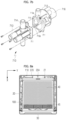
- FIG. 8a is a cross-sectional view taken along line D-D' of the shoes care device 1 illustrated in FIG. 3 .
- FIG. 8b is a view illustrating a state in which the main shelf 40 is removed from the shoes care device 1 illustrated in FIG. 8a .
- FIG. 9 is a cross-sectional view taken along line E-E' of the shoes care device 1illustrated in FIG. 3 .
- FIG. 10a is an exploded perspective view illustrating a drying module in the shoes care device 1 according to one embodiment of the present invention.
- FIG. 10b is an exploded perspective view illustrating a partial configuration of the drying module at a part to which the damper 350 is coupled.
- the dehumidifying part 330 may be used as a means that dehumidifies air.
- the dehumidifying part 330 may be provided inside the module housing 200.
- the dehumidifying part 330 is configured to have a predetermined volume.
- the dehumidifying part 330 may be configured to be porous by itself. A plurality of pores may be formed over an entire volume of the dehumidifying part 330, and air may move by penetrating the dehumidifying part 330 through such pores.
- the dehumidifying part 330 When the dehumidifying part 330 is composed of a combination of a plurality of dehumidifying materials, the plurality of dehumidifying materials may be fixed to each other by a separate fixing means, or may be fixed to each other by adhesion.
- the dehumidifying part 330 may be formed of dehumidifying materials, and may be configured to include the dehumidifying materials.
- the dehumidifying material 331 is configured to include a material capable of reducing humidity by absorbing moisture in the air.
- the dehumidifying material 331 may be formed of various materials or a combination of the materials within the range of absorbing or adhering the moisture in the air, and may be formed in various shapes and structures.
- the dehumidifying material 331 may be referred to as a desiccant or an adsorbent.
- the dehumidifying material 331 according to one embodiment of the present invention may be formed of a microporous material.
- the dehumidifying material 331 according to one embodiment of the present invention may include silica gel, activated carbon, activated alumina (AL2O3), diatomaceous earth, etc.
- the dehumidifying material 331 may be formed of zeolite or may be configured to include zeolite.
- the zeolite is a natural and synthetic silicate mineral in which tunnels or open channels having a size of approximately 3 to 10 angstroms (A) are regularly arranged, and may function as dehumidification by adsorbing the moisture in the air.
- the zeolite When the zeolite is heated, moisture adsorbed on the zeolite may be separated into a large amount of steam. According to the characteristics of the zeolite, the zeolite may be regenerated in a state capable of not only performing the dehumidification function to remove the moisture from the air but also performing the dehumidification function by heating the zeolite and separating the moisture adsorbed to the zeolite.
- the zeolite may be formed in the form of small grains (or stones) having the size (diameter) of several micrometers to several tens of micrometers, and the dehumidifying material 331 described in one embodiment of the present invention may refer to a combination of the grains (or stones).
- Each of the grains (or stones) may be agglomerated or combined with each other to form a single structure.
- the dehumidifying part 330 may include a dehumidifying body 330a and the dehumidifying material 331.
- the dehumidifying body 330a may be formed to have a predetermined volume. In one embodiment, the dehumidifying body 330a may be formed in a substantially hexahedral shape.
- the dehumidifying body 330a may be provided with a plurality of dehumidification through holes 332 penetrated in one direction.
- a cross section of the dehumidifying through hole 332 may be formed in a circular shape, a polygonal shape, etc.
- the dehumidifying through hole 332 may have a hexagonal cross section.
- the dehumidifying through hole 332 may all have the same shape and size, or may have different shapes and sizes.
- the dehumidifying body 330a may be formed of or include materials such as synthetic resin, metal, ceramic, etc.
- the dehumidifying body 330a may be formed of a combination of fibers, and may be formed of a nonwoven fabric, etc.
- the dehumidifying material 331 may be coated on the dehumidifying body 330a.
- the dehumidifying material 331 may be coated on the outside and inside of the dehumidifying body 330a. Specifically, the dehumidifying material 331 may be coated on a surface in which the dehumidifying through hole 332 is formed.
- the zeolite When the dehumidifying body 330a is formed of a combination of fibers, the zeolite may be first coated on each fiber as the dehumidifying material 331, and the zeolite-coated fiber may be processed to form the dehumidifying body 330a and simultaneously form the dehumidifying part 330.
- the dehumidifying part 330 may be formed by coating the gelled zeolite precursor on the dehumidifying body 330a or materials constituting the dehumidifying body 330a and then performing heat treatment when the dehumidifying material 331 is formed of the zeolite.
- the coating of the dehumidifying material 331 may be performed by using various known or possible methods, and is not limited to a certain manufacturing method related to the coating of the dehumidifying material 331.
- the blowing part 310 is provided inside the connection path F10.
- a blowing fan 313 may be provided inside the blowing part 310. Since the blowing part 310 is provided in the connection path F10, air flows in the connection path F10 when the blowing part 310 is driven, and since the connection path F10 also communicates with the accommodation space 101 of the inner cabinet 100, the air flows and moves in the accommodation space 101 by driving the blowing part 310.
- connection path F10 the air may be sucked from the inner cabinet 100 into the connection path F10 by the driving of the blowing part 310 (a rotation of the blowing fan 313), and the air inside the connection path F10 may be ventilated.
- the blowing part 310 is provided inside the module housing 200 forming the connection path F10, and the blowing part 310 is driven to suction the air inside the inner cabinet 100 into an inlet 203.
- the air inside the connection path F10 passes through the module housing 200 constituting the connection path F10, the dry air duct 370, and a nozzle duct 810 and is then discharged back into the inner cabinet 820.
- the flow of air may be generated in the shoes care device 1 by the driving of the blowing part 310.
- Dry air may be supplied to the inside of the inner cabinet 100 by the blowing part 310.
- the heating part 320 is provided at one side of the dehumidifying part 330 and the blowing part 310 in the connection path F10.
- the heating part 320 may be provided inside the module housing 200. Based on a movement direction of the air inside the module housing 200, the module housing 200 may be arranged in an order of the blowing part 310, the heating part 320, and the dehumidifying part 330. That is, the air introduced into the outlet 203 of the module housing 200 moves along the connection path F10 by passing sequentially through the blowing part 310, the heating part 320, and the dehumidifying part 330.
- the heating part 320 is disposed inside the module housing 200 and is configured to heat the air of the module chamber 210 inside the module housing 200.
- the heating part 320 may be configured to heat the dehumidifying part 330.
- the heating part 320 may be configured to heat the dehumidifying material 331 constituting the dehumidifying part 330.
- the air heated by the heating part 320 by the driving of the blowing part 310 moves directly to the dehumidifying part 330, thus heating the dehumidifying part 330.
- the heating part 320 is disposed inside the module housing 200 adjacent to the dehumidifying part 330.
- the heating part 320 is disposed inside the module housing 200 adjacent to the dehumidifying part 330 based on a movement path of the air inside the module housing 200.
- the dehumidification by the dehumidifying material 331 or the regeneration of the dehumidifying material 331 may be achieved by selectively heating the heating part 320.
- the heating part 320 may be fixedly coupled to the module housing 200 in the module housing 200.
- the heating part 320 may be made up of various devices and structures within a range capable of heating the air inside the module housing 200 or supplying heat to the dehumidifying part 330.
- the heating part 320 may be formed of an electric heater 321.
- the heating part 320 may include the heater 321.
- the heater 321 includes a heating element, and may be configured to supply heat to the periphery while the heating element generates heat by supplied electric energy.
- the heater 321 may include a nichrome wire as the heating element.
- the heater 321 of the heating part 320 may be formed in a ring shape, and the air may move by penetrating the center and surroundings of the ring-shaped heater 321 and be simultaneously heated.
- the heater 321 of the heating part 320 may be repeatedly formed in a second module chamber 213 along the movement direction of air.
- the heater 321 of the heating part 320 may be formed in a circular ring shape or a rectangular ring shape.
- the heating part 320 may include a heater flange 322 to which the heater 321 is fixed.
- the heater flange 322 may be formed in the form of a metallic plate.
- the heater flange 322 may be formed of a combination of flat plates in the second module chamber 213 along the movement direction of air.
- the heater flange 322 has a cross section that may be formed of a plate shape or a combination of plates in the second module chamber 213 along the movement direction of air (the second direction (Y direction)).
- the heater flange 322 may include an outer flange 322a and an inner flange 322b.
- the outer flange 322a may be formed in a tubular shape along the second direction (Y direction). An interior of the outer flange 322a is provided with a space to move air along the movement direction of air (a direction parallel to the second direction (Y direction)) in the second module chamber 213.
- the inner flange 322b is fixed to the interior of the outer flange 322a.
- the inner flange 322b may include two or more plates crossing each other, and the heater 321 of the heating part 320 may be fixed to the inner flange 322b.
- the heater flange 322 may be formed in various forms that fix the heater 321 of the heating part 320 and do not interfere with a flow of air moving through the second module chamber 213.
- the blowing part 310, the heating part 320, the dehumidifying part 330, and the module housing 200 may form one set.
- the set may be provided in a plural form.
- the shoes care device 1 according to one embodiment may be provided with two sets.
- Such a set may be provided in each of the first management device 2a and the second management device 2b.
- Such a set may form a drying module DM in the shoes care device 1 according to one embodiment of the present invention.
- the drying module DM may include the module housing 200, the blowing part 310, the heating part 320, and the dehumidifying part 330. Furthermore, the drying module DM is provided in each of the first management device 2a and the second management device 2b.
- a plurality of drying modules DM may be provided.
- a pair of drying modules DM may be provided.
- one of the drying modules DM may form a 'drying module A (DM1) ' as a drying module of the first management device 2a, and the other may form a 'drying module B (DM2) ' as a drying module of the second management device 2b.
- the 'drying module' described in one embodiment of the present invention may be understood to refer to each of the 'drying module A' and the 'drying module B' except as otherwise particularly limited.
- the drying module A (DM1) and the drying module B (DM2) may operate in different modes.
- the drying module A DM1 operates in a moisture absorption mode
- the drying module B DM2 may operate in a regeneration mode.
- the drying module B DM2 may operate in the moisture absorption mode.
- the 'moisture absorption mode' described in the present invention means a case in which the dehumidifying part 330 adsorbs moisture in the air, and the 'regeneration mode' means a case in which the moisture adsorbed to the dehumidifying part 330 is separated by heating the dehumidifying part 330.
- both the drying module A DM1 and the drying module B DM2 may operate in the moisture absorption mode or may operate in the regeneration mode.
- the module housing 200 may be fixedly coupled to a lower side of the inner cabinet 100.
- the module housing 200 may be detachably coupled to a lower side of the inner cabinet 100.
- the module housing 200 includes the module chamber 210 that is a space having other components accommodated inside. That is, the module chamber 210 is a space inside the module housing 200 distinguished from an external space of the module housing 200. As described above, the module housing 200 forms part of the connection path F10, and accordingly, the module chamber 210 is configured to communicate with a space outside the module housing 200. The module chamber 210 communicates with the accommodation space 101 of the inner cabinet 100.
- the module housing 200 may include a module case 201 and a module cover 202.
- the module case 201 and the module cover 202 may be formed by injection molding, respectively, and may be assembled with each other after manufacturing to form the module housing 200.
- the module case 201 is formed in the form of a container that is concave substantially downwards, and forms the module chamber 210 of the module housing 200.
- the module case 201 may be configured in the form of a container opened upwards, and includes a module opening 201a.
- an area of the module opening 201a may be larger than or equal to an area of the module chamber 210.
- the module chamber 210 may include a first module chamber 212, a second module chamber 213, and a third module chamber 214.
- the module chamber 210 may include a suction module chamber 211.
- a module partition wall 220 may be formed inside the module housing 200. Furthermore, the module partition wall 220 guides the movement of air so that air moves in a predetermined direction inside the module housing 200.
- the suction module chamber 211 is a first space where air is introduced into the module housing 200.
- the first module chamber 212 is a space in which the blowing part 310 is accommodated
- the second module chamber 213 is a space in which the heating part 320 is accommodated
- the third module chamber 214 is a space in which the dehumidifying part 330 is accommodated.
- the suction module chamber 211, the first module chamber 212, the second module chamber 213, and the third module chamber 214 may be formed at different positions in a plan view.
- the air of the module chamber 210 may be configured to move the suction module chamber 211, the first module chamber 212, the second module chamber 213, and the third module chamber 214 sequentially. That is, when the blowing part 310 is driven, air moves sequentially through the suction module chamber 211, the first module chamber 212, the second module chamber 213, and the third module chamber 214 inside the module housing 200.
- the module case 201 may include a dry air outlet 231 and a wet air outlet 232.
- the dry air outlet 231 may be formed in a hole shape opened to allow air in the third module chamber 214 to flow out.
- the dry air outlet 231 is formed adjacent to the third module chamber 214.
- the dry air outlet 231 may be formed on one edge of the module case 201. Furthermore, the dry air outlet 231 may be connected to the accommodation space 101 through the dry air duct 370 and the nozzle duct 810.
- the wet air outlet 232 may be formed in a hole shape opened to allow the air in the third module chamber 214 to flow out.
- the wet air outlet 232 is formed adjacent to the third module chamber 214.
- the wet air outlet 232 may be formed on a frame on one side of the module case 201. Furthermore, the wet air outlet 232 may be connected to the condenser 400.
- the dry air outlet 231 and the wet air outlet 232 may be formed adjacent to each other.
- the dry air outlet 231 and the wet air outlet 232 may be formed adjacent to any one vertex part of the module housing 200.
- the suction module chamber 211 is formed adjacent to the first module chamber 212, and a bottom surface of the suction module chamber 211 may be inclined downwardly toward the first module chamber 212. Accordingly, air introduced into the suction module chamber 211 may naturally move toward the first module chamber 212 by hitting the bottom surface of the suction module chamber 211 forming an inclined surface, and a condensed water introduced into the suction module chamber 211 may move along the bottom surface of the suction module chamber 211 forming the inclined surface, and may move to the first module chamber 212.
- the blowing part 310 may be assembled to the module housing 200 while being spaced apart from a bottom surface of the first module chamber 212. Furthermore, in this case, the blowing part 310 may be configured such that air may be introduced from a lower side of the first module chamber 212 to an interior of the blowing part 310 inside the first module chamber 212.
- the module case 201 may include a first condensed water discharge hole 233.
- the first condensed water discharge hole 233 is formed in a hole shape penetrating the module case 201.
- the first condensed water discharge hole 233 is formed on an edge of the module case 201 adjacent to a condenser 400 and formed to be equal to or lower than the bottom surface of the first module chamber 212, and communicates with the condenser 400.
- the first condensed water discharge hole 233 may form the lowest part, or the bottom surface of the first module chamber 212 may be formed such that a height thereof is lowered toward or at least equal to the first condensed water discharge hole 233.
- the first condensed water discharge hole 233 may be lower than the bottom surface of the first module chamber 212, and accordingly, the condensed water introduced into the first condensed water discharge hole 232 may move toward the first condensed water discharge hole 233 and flow into the condenser 400 through the first condensed water discharge hole 233.
- the air inside the condenser 400 may flow into the module housing 200 through the first condensed water discharge hole 233.
- the air introduced into the module housing 200 through the first condensed water discharge hole 233 from an interior of the condenser 400 may move along the first module chamber 212, the second module chamber 213, and the third module chamber 214 by an operation of the blowing part 310 and may be introduced again into the condenser 400 and condensed.
- the shoes care device 1 includes the condenser 400 coupled to an outer surface of the inner cabinet 100 and forming a regeneration path F20.
- the first module chamber 212 may be provided between the second module chamber 213 and the condenser 400. Since the first module chamber 212 is disposed between the second module chamber 213 and the condenser 400, a direct heat exchange between the condenser 400 and the heating part 320 is blocked, and the heat may be prevented from being transferred to the condenser 400 when the heating part 320 is heated inside the second module chamber 213.
- condensation depending on heating of air by the heater 321 of the heating part 320 and cooling of air inside the condenser 400 may be effective performed.
- the dehumidifying part 330 may be coupled to the module housing 200 while being spaced apart from a bottom surface of the third module chamber 214. Furthermore, in this case, the air inside the third module chamber 214 may move downwards through the dehumidifying part 330 from an upper side of the third module chamber 214.
- the module case 201 may include a second condensed water discharge hole 234.
- the second condensed water discharge hole 234 is formed in a hole shape penetrating the module case 201.
- the second condensed water discharge hole 234 is formed on the edge of the module case 201 adjacent to the condenser 400 and formed to be equal to or lower than the bottom surface of the third module chamber 214, and communicates with the condenser 400.
- the second condensed water discharge hole 234 may form the lowest part, or the bottom surface of the third module chamber 214 may be formed such that a height thereof is lowered toward or at least equal to the second condensed water discharge hole 234.
- the second condensed water discharge hole 234 may be formed adjacent to the wet air outlet 232.
- the second condensed water discharge hole 234 may be lower than the bottom surface of the third module chamber 214, and accordingly, condensed water introduced into the third module chamber 214 may move toward the second condensed water discharge hole 234, and may flow into the condenser 400 through the second condensed water discharge hole 234.
- the second condensed water discharge hole 234 is a hole in which the module housing 200 and the condenser 400 communicate with each other, the air inside the condenser 400 may flow into the module housing 200 through the second condensed water discharge hole 234. In this way, the air introduced from the interior of the condenser 400 into the module housing 200 through the second condensed water discharge hole 234 moves directly to the wet air outlet 232 by the driving of the blowing part 310, and may be introduced again into the condenser 400 and condensed.
- the module housing 200 may include the module cover 202.
- the module cover 202 is coupled to the module case 201 while shielding the module opening 201a from an upper side of the module case 201.
- the module cover 202 may be detachably coupled to the module case 201.
- a plurality of locking projections 292 may protrude from one of the module cover 202 and the module case 201, and a plurality of locking grooves 291 into which the locking projections 292 are inserted and locked may be formed on the other.
- the locking projections 292 and locking grooves 291 are provided in a plural form, respectively, and may be spaced apart along an edge of the module housing 200 and repeatedly formed.
- the module cover 202 may shield the blowing part 310, the heating part 320, and the dehumidifying part 330 and may be coupled to the module case 201.
- the shoes care device may be formed in a structure in which the dehumidifying part 330 may be detachable from the module housing 200.
- the structure of the shoes care device provides an advantageous advantage in maintaining and managing the dehumidifying part 330 and the shoes care device 1 on the whole.
- the dehumidifying part 330 may be repeatedly used by regeneration, but with the repeated use, the dehumidifying part 330 needs to be replaced.
- the shoes care device 1 may be configured to separate and replace the dehumidifying part 330.
- the module cover 202 of the module housing 200 may form a bottom surface of the inner cabinet 100.
- the module cover 202 may form a boundary surface between the inner cabinet 100 and the module housing 200.
- the module cover 202 may be formed in a substantially rectangular shape.
- the module cover 202 may be configured in substantially parallel with the horizontal direction.
- the module cover 202 may be inclined to any one side.
- an upper surface of the module cover 202 may be inclined downwardly toward the first direction (X direction) (a front side of the shoes care device 1).
- the main shelf 40 is mounted in close contact with an upper side surface of the module cover 202, and the main shelf 40 mounted on the upper side surface of the module cover 202 is also configured to be inclined when the upper side surface of the module cover 202 is inclined.
- water e.g., condensed water
- the shoes care device 1 may include a dehumidifying material cover 241.
- the dehumidifying material cover 241 forms part of the module cover 202 that is the bottom of the inner cabinet 100. Furthermore, the dehumidifying material cover 241 may be detached from the module cover 202 of the inner cabinet 100 or may be hinge-coupled to the module cover 202.
- a dehumidifying material exit 240 which is an opening of a shape and a size corresponding to the dehumidifying material cover 241 may be formed.
- the dehumidifying material cover 241 may be configured to open and close the dehumidifying material exit 240.
- the dehumidifying material cover 241 may be tightly coupled to the dehumidifying material exit 240. At least a part of the dehumidifying material cover 241 may be separated from the module cover 202.
- the dehumidifying material exit 240 of the module cover 202 may be opened while completely separating the dehumidifying material cover 241 from the module cover 202, and in another embodiment, the dehumidifying material cover 241 of the module cover 202 may be opened while rotating the dehumidifying material cover 241 around a hinge axis.
- the dehumidifying part 330 may be introduced into or withdrawn from the module housing 200 through the dehumidifying material exit 240.
- the dehumidifying material exit 240 and the dehumidifying material cover 241 may be formed in a position corresponding to the third module chamber 214 in a plan view. That is, the dehumidifying material exit 240 and the dehumidifying material cover 241 may be formed directly above the third module chamber 214.
- the shoes care device 1 according to one embodiment of the present invention may be configured such that the first module chamber 212 and the second module chamber 213 are not exposed in a plan view in a state where the dehumidifier cover 241 is opened.
- the dehumidifying material cover 241 When the dehumidifying material cover 241 is opened in the module cover 202, the third module chamber 214 disposed on a lower part of the module cover 202 is exposed through the dehumidifying material exit 240 of the module cover 202, and the dehumidifying part 330 may be settled inside the module case 201, or may be immediately withdrawn and separated from the module case 201.
- the sizes and shapes of the dehumidifying material cover 241 and the dehumidifying material exit 240 are variously provided within the range capable of withdrawing or inserting the dehumidifying part 330.
- the dehumidifying material cover 241 may be formed in a rectangular plate shape.
- the length of the dehumidifying material cover 241 in the first direction (X direction) may be equal to or longer than the length of the dehumidifying part 330, and the length of the dehumidifying material cover 241 in the second direction (Y direction) may be equal to or longer than the length of the dehumidifying part 330.
- the heating part 320 and the dehumidifying part 330 are formed at different positions in a top plane view, and when the dehumidifying material cover 241 is opened on the module cover 202 that forms the bottom surface of the inner cabinet 100, the dehumidifying part 330 disposed directly below the dehumidifying material cover 241 may be withdrawn from the module housing 200, and the dehumidifying part 330 may be easily replaced by the user.
- the blowing part 310 accommodated in the first module chamber 212 and the heating part 320 accommodated in the second module chamber 213 are not exposed. That is, since the blowing part 310 and the heating part 320 are not directly exposed to the user, safety accidents due to an unintended operation of the blowing part 310 and/or the heating part 320 can be prevented.
- the dehumidifying material cover 241 may be configured to separately shield the dehumidifying part 330.
- a space between the dehumidifying material cover 241 and the dehumidifying part 330 may form a part of the connection path F10.
- the outlet 203 forms an inlet through which the air inside the inner cabinet 100 is sucked into the module housing 200.
- the outlet 203 may form a start part of the connection path F10.
- the outlet 203 may be formed in the shape of a hole vertically penetrated from the bottom surface (the upper surface of the module cover 202) of the inner cabinet 100.
- a network such as a grid shape, a mesh shape, etc., may be formed on the outlet 203.
- the outlet 203 may be formed parallel to the second direction (Y direction). That is, the outlet 203 may be formed in a long hole shape in the module cover 202 along the second direction (Y direction).
- the outlet 203 may be formed on an edge of the module cover 202.
- the outlet 203 may be formed on the edge of the module cover 202 along the second direction (Y direction).
- the outlet 203 may be formed on a front part or a rear part of the module cover 202 based on the first direction (X direction).
- the outlet 203 may be disposed relatively close to the door 30 in the module cover 202. That is, the outlet 203 may be disposed relatively in the front of the module cover 202.
- the upper surface of the module cover 202 may be inclined downwardly toward the outlet 203. That is, a part of the module cover 202 where the outlet 203 is formed may be configured to be the lowest. Accordingly, when water is present on the module cover 202 or the main shelf 40, such water may flow along the surface of the module cover 202 by gravity and flow into the inlet 203.
- the module chamber 210 is provided inside the module housing 200, and the module chamber 210 includes a first module chamber 212, a second module chamber 213, and the third module chamber 214.
- the first module chamber 212, the second module chamber 213, and the third module chamber 214 may be formed at different positions in a plan view. That is, the blowing part 310, the heating part 320, and the dehumidifying part 330 may be disposed at different positions in the module housing 200.
- the blowing part 310, the heating part 320, and the dehumidifying part 330 which are main means for drying the air inside the inner cabinet 100 and main means for regenerating the dehumidifying part 330, are disposed together in the module chamber 210 of the module housing 200. Accordingly, the blowing part 310, the heating part 320, and the dehumidifying part 330 are disposed at positions considerably close to each other.
- the module case 201 of the module housing 200 may be integrally formed by injection molding.
- the bottom parts of the module housing 200 may be integrally formed, the bottom parts may not be assembled with each other, and no gaps may be formed in the bottom parts.
- the condensed water can be effectively prevented from leaking from the module housing 200.
- a vertical height of the module housing 200 can be minimized.
- the shoes care device 1 When moisture remains at an unintended part inside the shoes care device 1, such moisture may reproduce bacteria or cause odors. This is why there is need for countermeasures to solve the problems, and the shoes care device 1 according to one embodiment of the present invention can effectively prevent water from leaking in consideration of such problems.
- the air in the module chamber 210 may sequentially move the first module chamber 212, the second module chamber 213, and the third module chamber 214. Accordingly, since the third module chamber 214 and a drying flow path F10b may be connected in the shortest distance, which provides excellent drying efficiency by the dehumidifying part 330, and air heated by the heating part 320 moves directly to the dehumidifying part 330 to form the shoes care device 1 with excellent regeneration efficiency.
- the module housing 200 includes the suction module chamber 211, and the bottom surface of the suction module chamber 211 may be inclined downwardly toward the first module chamber 212. Accordingly, the air introduced through the outlet 203 moves naturally to the first module chamber 212 by hitting the bottom surface of the suction module chamber 211, and the condensed water introduced into the outlet 203 moves to the first module chamber 212 such that the condensed water can be easily drained.
- the shoes care device 1 may include the condenser 400, and the module case 201 may include the first condensed water discharge hole 233.
- the module case 201 may include the second condensed water discharge hole 234. Accordingly, the dehumidifying part 330 may be effectively regenerated, and condensed water inside the module housing 200 may be easily discharged to the condenser 400.
- steam generated by the steam generator 700 is supplied to the accommodation space 101 of the inner cabinet 100, and to this end, the shoes care device 1 includes a steam inlet 204.
- the steam inlet 204 forms an inlet through which steam is supplied to the accommodation space 101 of the inner cabinet 100.
- the steam inlet 204 is formed in the module housing 200.
- the steam inlet 204 may be formed in a rear part of the module housing 200 based on the first direction (X direction).
- the steam inlet 204 may be formed to vertically penetrate the module housing 200.
- the steam inlet 204 may be formed to vertically penetrate the module case 201 and the module cover 202.
- the steam inlet 204 may be formed in the center in a right-left direction at the rear part of the module housing 200.
- the steam inlet 204 may be formed on a rear edge of the module housing 200, and may be formed directly behind a position where the third module chamber 214 is formed. The third module chamber 214 and the steam inlet 204 are shielded from each other.
- the module cover 202 forms the bottom surface of the accommodation space 101, and when the module housing 200 is coupled to the inner cabinet 100, the steam inlet 204 is formed behind the bottom of the inner cabinet 100.
- the steam generator 700 and the steam valve 710 are disposed in a lower part, the distance from the steam generator 710 to the steam inlet 204 can be reduced by forming the module housing 200, and the steam inlet 204 in a rear part of the module housing 200, and an increase in the load required for the supply of steam can be prevented. Accordingly, steam may be smoothly supplied from the steam generator 700 to the steam inlet 204
- FIG. 11 is a diagram illustrating a connection relationship between components and a flow of fluid in the shoes care device 1 according to one embodiment of the present invention.
- connection path F10 forms a movement path of air connected from the outlet 203 to the nozzle 820. That is, the outlet 203 may form an inlet of the connection path F10, and the nozzle 820 may form an outlet of the connection path F10.
- the outlet 203 may be coupled to communicate with the inner cabinet 100, and the nozzle 820 may be provided inside the inner cabinet 100. Except the outlet 203 and the nozzle 820, one part of the connection path F10 may be provided inside the inner cabinet 100, and the other part may be provided outside the inner cabinet 100.
- connection path F10 The air inside the inner cabinet 100 moves to the connection path F10 through the outlet 203, and the air passing through the connection path F10 moves back into the inner cabinet 100 through the nozzle 820. As such air flow is repeated, the air circulation is performed in the shoes care device 1.
- a hole through which air is discharged is formed in the accommodation space 101 of the inner cabinet 100, and the nozzle 820 may form a last part of the connection path F10.
- the nozzle 820 is configured to be movable to various positions inside the inner cabinet 100, the shoes may be managed in various positions.
- the dehumidifying part 330 is disposed in the connection path F10.
- the air moving through the connection path F10 passes through the dehumidifying part 330, and the dehumidifying part 330 absorbs moisture from the air moving through the connection path F10 such that the air from which moisture has been removed may be supplied into the inner cabinet 100.
- connection path F10 may be divided into a conversion flow path F10a and a drying flow path F10b.
- the conversion flow path F10a and the drying flow path F10b form a movement path of air sequentially connected to each other.
- the air in the connection path F10 may sequentially move through the conversion flow path F10a and the drying flow path F10b.
- the conversion flow path F10a forms an upstream section of the connection path F10, which is connected to the outlet 203.
- the conversion flow path F10a may be a section in which the blowing part 310, the heating part 320, and the dehumidifying part 330 are disposed.
- the conversion flow path F10a may be formed by the module housing 200, and the module chamber 210 inside the module housing 200 may form the conversion flow path F10a.
- the conversion flow path F10a may be a section in which humid air moves and dries.
- the conversion flow path F10a may be a section in which air is dehumidified by the dehumidifying part 330.
- the conversion flow path F10a may be a section in which the dehumidifying part 330 (the dehumidifying material 331) are regenerated.
- the drying flow path F10b forms a downstream section of the connection path F10, which connects the conversion flow path F10a to the nozzle 820.
- a flow path formed by the drying air duct 370, the nozzle duct 810, and the nozzle 820 may form the drying flow path F10b.
- the drying passage F10b may be a section in which dry air with moisture removed therefrom moves.
- the drying flow path F10b When the drying module DM operates in the moisture absorption mode, the drying flow path F10b communicates with the conversion flow path F10a, and when the drying module DM operates in the regeneration mode, the drying flow path F10b and the conversion flow path F10a may not communicate with each other such that the drying flow path F10b and the conversion flow path F10a block each other.
- the dry air duct 370 may be fixedly coupled to an outer wall surface of the inner cabinet 100, and the nozzle duct 810 may be provided inside the inner cabinet 100.
- a flow path may be formed between the dry air duct 370 and the inner cabinet 100 (the inner rear plate 110), and such a flow path may form a part of the drying flow path F10b.
- a lower part of the dry air duct 370 communicates with the dry air outlet 231 of the module housing 200, an upper part thereof communicates with the nozzle duct 810, which connect the interior of the module housing 200 and the interior of the nozzle duct 810 for mutual communication.
- the air is dehumidified by the dehumidifying part 330 and converted into dry air, and the dry air can be resupplied to the accommodation space 101 of the inner cabinet 100 through the drying flow path F10b.
- the regeneration path F20 forms a movement path of a fluid.
- the regeneration path F20 forms a passage through which air and/or condensed water inside the shoes care device moves.
- the regeneration path F20 forms a path through which air and/or condensed water passing through the dehumidifying part 330 moves when the dehumidifying material 331 is regenerated.
- the regeneration path F20 may be entirely or partially formed of a pipe, a hose, a tube, a duct, a housing, or a combination thereof.
- the shoes care device 1 includes the regeneration path F20, and when the dehumidifying material 331 is regenerated, air passing through the dehumidifying part 330 is not ventilated to the nozzle 820 but moves through the regeneration path F20.
- the regeneration path F20 is a flow path branched from the connection path F10.
- the regeneration path F20 may be branched from the connection path F10 to form a path different from that of the drying flow path F10b of the connection path F10.
- the regeneration path F20 is connected to the sump 600.
- the regeneration path F20 may be a section that connects the conversion flow path F10a and the sump 600.
- the regeneration path F20 may be a section in which humid air separated from the dehumidifying part 330 moves.
- the condenser 400 forms a regeneration path F20. Moisture separated from the dehumidifying material 331 may be condensed after moving to the condenser 400 along with air moving along the regeneration path F20. In addition, condensed water condensed in the condenser 400 may be moved to the sump 600 through the regeneration path F20, collected from a lower part of the sump 600, and then discharged to the drain tank 70, discharged to the outside, or pressed to the steam generator 700.
- the regeneration path F20 when the drying module DM operates in the regeneration mode, the regeneration path F20 communicates with the conversion flow path F10a, and when the drying module DM operates in the moisture absorption mode, the regeneration path F20 and the conversion flow path F10 may not communicate with each other such that the regeneration path F20 and the conversion flow path F10 block each other.
- the damper 350 may be formed in the form of a damper valve.
- the damper 350 may be rotatably coupled to the module housing 200.
- the damper 350 may be coupled to the module housing 200 in a form accommodated in the module housing 200.
- the dry air outlet 231 forming an inlet of the drying flow path F10b is formed as a passage of the connection path F10, and the wet air outlet 232 forming an inlet of the regeneration path F20 is formed.
- the damper 350 controls a movement path of air passing through the dehumidifying material 331 in the module housing 200. Depending on the operation of the damper 350, the air passing through the dehumidifying material 331 may move into the inner cabinet 100 through the nozzle 820 or may move into the regeneration path F20.
- the damper 350 may be configured to open the regeneration path F20 while blocking the drying flow path F10b, or to open the drying flow path F10b while blocking the regeneration path F20.
- the damper 350 may be configured to selectively shield the dry air outlet 231 and the wet air outlet 232.
- the damper 350 may be configured to selectively seal the dry air outlet 231 and the wet air outlet 232.
- the damper 350 may selectively block one of the dry air outlet 231 and the wet air outlet 232.
- the damper 350 opens the dry air outlet 231 while blocking the wet air outlet 232, the air passing through the dehumidifying material 331 may move into the inner cabinet 100 through the nozzle 820, and when the damper 350 opens the wet air outlet 232 while blocking the dry air outlet 231, the air passing through the dehumidifying material 331 may be condensed while moving through the regeneration path F20.
- the damper 350 may be configured to be hinge-rotatable around a hinge axis 350a formed on one side.
- the hinge axis 350a of the damper 350 may be parallel to the third direction (Z direction).
- the shoes care device 1 may include a damper motor 351 configured to rotate the damper 350 around the hinge axis 350a of the damper 350.
- the damper motor 351 may be formed as an electric motor and may be configured to rotate the damper 350 bidirectionally.
- the damper 350 opens the dry air outlet 231 and seals the wet air outlet 232
- the air inside the inner cabinet 100 moves along the connection path F10 and is circulated by sequentially passing through the inlet 203, the module housing 200 (the blowing part 310 and the dehumidifying part 330, the dry air outlet 231, the dry air duct 370, the nozzle duct 810, and the nozzle 820.
- the damper 350 seals the dry air outlet 231 and opens the wet air outlet 232, the air moves along the conversion flow path F10a and the regeneration path F20 and is circulated by sequentially passing through the module housing 200 (the blowing part 310, the heating part 310, and the dehumidifying part 330), the wet air outlet 232, and the condenser 400.
- the controller 10 may control the damper motor 351 such that the damper 350 closes the dry air outlet 231 and opens the wet air outlet 232 when the heating part 320 is turned on.
- the controller 10 may control the damper motor 351 such that the damper 350 opens the dry air outlet 231 and closes the wet air outlet 232 when the heating part 320 is turned off.
- the damper 350 may open the drying flow path F10b and close the regeneration path F20 when the heating part 320 is turned off, and may close the drying flow path F10b and open the regeneration path F20 when the heating part 320 is turned on.
- the damper motor 351 may be controlled individually in each of the first management device 2a and the second management device 2b.
- the damper 350 seals the wet air outlet 232 and opens the dry air outlet 231 of the second management device 2b
- the drying module B (DM2) of the second management device 2b when the damper 350 opens the wet air outlet 232 and seals the dry air outlet 231, the air in the conversion flow path F10a of the first management device 2a may flow through the drying flow path F10b, and the air in the conversion flow path F10a of the second management device 2b may flow through the regeneration path F20.
- the drying module A (DM1) of the first management device 2a may operate in the moisture absorption mode
- the drying module B (DM2) of the second management device 2b may operate in the regeneration mode.
- the damper 350 when in the drying module A (DM1) of the first management device 2a, the damper 350 opens the wet air outlet 232 and seals the dry air outlet 231, and in the drying module B (DM2) of the second management device 2b, the damper 350 seals the wet air outlet 232 and opens the dry air outlet 231, the air in the conversion flow path F10a of the first management device 2a may flow along the regeneration path F20, and the air in the conversion flow path F10a of the second management device 2b may flow along the drying flow path F10b. Furthermore, in this case, the drying module A (DM1) of the first management device 2a may operate in the regeneration mode, and the drying module B (DM2) of the second management device 2b may operate in the moisture absorption mode.
- both the drying module A DM1 of the first management device 2a and the drying module B (DM2) of the second management device 2b when the damper 350 seals the wet air outlet 232 and opens the dry air outlet 231, both the drying module A DM1 and the drying module B (DM2) may operate in the moisture absorption mode.
- both the drying module A (DM1) of the first management device 2a and the drying module B (DM2) of the second management device 2b when the damper 350 seals the dry air outlet 231 and opens the wet air outlet 232, both the drying module A (DM1) and the drying module B (DM2) may operate in the regeneration mode.
- the first management device 2a and the second management device 2b individually include the inner cabinet 100, the connection path F10, the blowing part 310, and the dehumidifying part 330.
- the shoes care device 1 includes the steam generator 700 and the steam valve 710. Accordingly, the degree of the supply of steam, the degree of dehumidification by the dehumidifying part 330, and the flow of air circulated along the connection path F10 may be different in each of the first management device 2a and the second management device 2b, and the first management device 2a and the second management device 2b may manage shoes under different conditions.
- the first management device 2a and the second management device 2b include the module housing 200, the blowing part 310, the heating part 320, the dehumidifying part 330, and the drying flow path F10b, respectively.
- the air and condensed water moving in the first management device 2a and the air and condensed water moving in the second management device 2b move along different paths, thereby achieving accurate control intended in each of the first management device 2a and the second management device 2b.
- the first management device 2a and the second management device 2b share and use the steam generator 700, the steam generator 700 can be efficiently utilized in the shoes care device 1, and the shoes care device 1 can efficiently utilize the space.
- the dehumidifying part 330 may be regenerated in the other, and the efficient management of the shoes and efficient use of the shoes care device 1 can be achieved.
- the first management device 2a and the second management device 2b each include the regeneration path F20 and the damper 350 individually.
- the controller 10 may control the heating part 320 (the heater 321) and the damper 350 to interwork with each other.
- the controller 10 may control the damper 350 to open the drying flow path F10b and close the regeneration path F20 when the heating part 320 is turned off, and may control the damper 350 to close the drying flow path F10b and open the regeneration path F20 when the heating part 320 is turned on.
- the controller 10 may control each component of the shoes care device 1 such that air flowing into the module chamber 210 from the accommodation space 101 and passing through the dehumidifying part 330 moves along the drying flow path F10b when the heating part 320 is turned off (when the heater 321 of the heating part 320 is turned off), and the air moves along the regeneration path F20 when the heating part 320 is turned on (when the heater 321 of the heating part 320 is turned on).
- Such control may be performed individually in each of the first management device 2a and the second management device 2b. Accordingly, since the movement path of air inside the module chamber 210 is changed depending on an operation of the heating part 320, the drying of the shoes and the regeneration of the dehumidifying part 330 can be effectively achieved.
- the controller 10 may control the steam valve 710 and the heating part 320 to interwork with each other.
- the controller 10 ma control the steam valve 710 such that when the heating part 320 of the first management device 2a is turned off, the valve disk 715 closes or opens the first valve outlet 713, when the heating part 320 of the first management device 2a is turned on, the valve disk 715 closes the first valve outlet 713, when the heating part 320 of the second management device 2b is turned off, the valve disk 715 closes or opens the second valve outlet 714, and when the heating part 320 of the second management device 2b is turned on, the valve disk 715 closes the second valve outlet 714.
- the supply of steam to the accommodation space 101 of the inner cabinet 100 and the operation of the heating part 320 inside the module housing 200 may interwork with each other to effectively perform the drying of the shoes and the regeneration of the dehumidifying part 330.
- the shoes care device 1 may include a first sensor 361 and a second sensor 362 (see FIG. 9 ).
- the first sensor 361 may be installed in the second module chamber 213 of the module housing 200, and the second sensor 362 may be installed in the third module chamber 214 of the module housing 200.
- the first sensor 361 may be configured to measure the temperature and/or humidity of the second module chamber 213, and the second sensor 362 may measure the temperature and/or humidity of the third module chamber 214.
- the first sensor 361 measures the temperature and/or humidity of air before passing through the dehumidifying part 330
- the second sensor 362 measures the temperature and/or humidity of air after passing through the dehumidifying part 330.
- the controller 10 may compare the temperature and/or humidity of the second module chamber 213 measured by the first sensor 361 with the temperature and/or humidity of the third module chamber 214 measured by the second sensor 362 to recognize a state and a change of the temperature and/or humidity inside the module housing, and may also check an operation state of the drying module DM.
- the controller 10 may recognize the temperature and humidity of the second module chamber 213 measured by the first sensor 361, and the temperature and humidity of the third module chamber 214 measured by the second sensor 362 to recognize a change in the humidity inside the module housing 200. Accordingly, the degree of dehumidification by the dehumidifying part 330 may be checked, and the degree of regeneration of the dehumidifying part 330 may be checked.
- the controller 10 may control the drying module DM to stop operating in the moisture absorption mode and operate in the regeneration mode if a humidity change amount of the second module chamber 213 recognized by the first sensor 361 and a humidity change amount of the third module chamber 214 recognized by the second sensor 362 is less than or equal to a reference value.
- the controller 10 may control the drying module DM to stop operating in the regeneration mode if the humidity change amount of the second module chamber 213 recognized by the first sensor 361 and the humidity change amount of the third module chamber 214 recognized by the second sensor 362 is less than or equal to the reference value.
- the shoes care device 1 further includes a third sensor 363 capable of measuring the amount of moisture adsorbed to the dehumidifying material 331, and the controller 10 may control the drying module DM to operate the regeneration mode until the amount of moisture measured by the third sensor 363 is less than or equal to a set value.
- the controller 10 may control all the heating parts 320 to operate until the amount of moisture measured by the third sensor 363 is less than or equal to the set value.
- the third sensor 363 may include a moisture sensor installed adjacent to the dehumidifying material 331 to measure the amount of moisture adsorbed to the dehumidifying material 331, and the type and number thereof may vary as necessary.
- the shoes care device 1 when the moisture adsorbed on the dehumidifying material 331 is sensed to exceed the reference value, the shoes care device 1 according to one embodiment of the present invention first regenerates all dehumidifying materials 331 until the moisture is less than or equal to the reference value. Accordingly, the dehumidifying material 331 can maintain an appropriate state for dehumidification all the times even when the shoes care device 1 operates to refresh the shoes.
- FIG. 12 is a view illustrating in more detail a nozzle duct 810 and a nozzle 820 installed in the inner cabinet 100 in the shoe care device 1 according to one embodiment of the present invention.
- FIG. 13 is a cross-sectional view illustrating coupling structures at one end and the other end of the nozzle duct 810 illustrated in FIG. 12 .
- FIG. 14 is a cross-sectional view illustrating a portion where the nozzle duct 810 in FIG. 12 is coupled to the inner cabinet 100.
- FIG. 15 is a cross-sectional view illustrating a portion where the nozzle duct 810 of FIG. 12 is coupled to the nozzle 820.
- FIGS. 16 and 17 are views illustrating the state in which the angle of the nozzle duct 810 of FIG. 12 is adjusted.
- FIG. 18 is a cross-sectional view illustrating the interior of the nozzle duct 810 of FIG. 12 .
- FIG. 19 is a view illustrating the nozzle duct 810 and the nozzle 820 of
- the shoe care device 1 may include an inner cabinet 100, an outlet 203 , a nozzle duct 810, a nozzle 820, a nozzle connector 830, a connection path F10, a blowing part 310, and a dehumidifying part 330.
- the nozzle duct 810 is a part that is hinged to the inner cabinet 100 at one end thereof and protrudes into the inner cabinet 100 to form an air passage.
- the nozzle 820 is coupled to the other end of the nozzle duct so that the nozzle duct may form a passage through which air moves to the nozzle 820.
- the position where the nozzle 820 is disposed inside the inner cabinet 100 may be varied.
- the one end of the nozzle duct 810 may be hinged to the inner cabinet 100. That is, a nozzle supporter hinge axis 813 provided at one end of the nozzle duct 810 may be coupled to the inner cabinet 100 to make the nozzle duct 810 rotatable around the nozzle supporter hinge axis 813.
- the nozzle 820 is a part that is hinged to the other end of the nozzle duct 810 to be insertable into a shoe from inside the inner cabinet 100 to spray air into the shoe.
- the air passing through the connection path F10 may be sprayed to the shoe inside the inner cabinet 100 through the nozzle 820.
- the nozzle 820 sprays air in the state of being inserted into the shoe, thereby ensuring that air is smoothly introduced into the shoe.
- the nozzle 820 may be hinged to the other end of the nozzle duct 810. That is, since the nozzle 820 is coupled to the nozzle hinge axis 825 formed at the other end of the nozzle duct 810, the nozzle 820 is rotatable around the nozzle hinge axis 825.
- the nozzle connector 830 is a part that is installed separately from the nozzle duct 810, hinged to the inner cabinet 100 at one end, and hinged to the nozzle 820 at the other end.
- the nozzle connector may ensure that the angle of the nozzle 820 is maintained constant even when the nozzle duct 810 performs hinge rotation.
- the nozzle 820 is also inclined integrally with the nozzle duct 810, making it difficult for the nozzle 820 to be inserted into the upper surface of a shoe.
- the nozzle duct 810 is disposed to be inclined, it may be desirable to adjust the angle of the nozzle 820 such that the nozzle is not inclined by a predetermined angle or more.
- a user may arbitrarily adjust the angle of the nozzle 820 such that the nozzle 820 is not inclined by a predetermined angle or more.
- the nozzle connector 830 installed separately from the nozzle duct 810, even when the user does not separately adjust the angle of the nozzle 820, it may be desirable for the nozzle 820 to always maintain its angle constant in the process of adjusting only the angle of the nozzle duct 810.
- the nozzle 820 may be desirable for the nozzle 820 to maintain the angle at which the lower discharge port 821 discharges air in the vertical direction.
- the first connection hinge axis 831 formed at one end of the nozzle connector 830 is coupled to the inner cabinet 100, so that the nozzle connector 830 can also be rotated around the first connection hinge axis 831.
- the nozzle 820 is coupled to the second connection hinge axis 832 formed at the other end of the nozzle connector 830, so that the nozzle 820 can also be rotated around the second connection hinge axis 832.
- the angle of the nozzle connector 830 may be changed correspondingly.
- the nozzle supporter hinge axis 813 and the first connection hinge axis 831 may maintain the distance therebetween even when the nozzle duct 810 and the nozzle connector 830 rotate by the same angle.
- the nozzle hinge axis 825 coupled to the nozzle 820 and the second connection hinge axis 832 may also maintain the distance therebetween.
- the lateral position of the nozzle hinge axis 825 may move toward the nozzle supporter hinge axis 813, and the longitudinal position of the nozzle hinge axis 825 may move downward.
- the lateral and longitudinal positions of the second connection hinge axis 832 may be moved to correspond to the lateral and longitudinal positions of the nozzle hinge axis 825.
- the nozzle hinge axis 825 and the second connection hinge axis 832 may move the lateral and longitudinal positions thereof equally while maintaining the same distance therebetween, even when the nozzle duct 810 and the nozzle connector 830 are changed to any angle, the angle of the nozzle 820 may be maintained constant.
- one end and the other end of the nozzle duct 810 are hinged to the inner cabinet 100 and the nozzle 820, respectively, and separately from the nozzle duct 810, one end and the other end of the nozzle connector 830 are hinged to the inner cabinet 100 and the nozzle 820, respectively, whereby even when the angle of the nozzle duct 810 is changed, the angle of the nozzle 820 is maintained constant. Therefore, shoe processing efficiency can be further improved by stably supplying air to a shoe.
- the nozzle 820 may include a nozzle body 822 hinged to the nozzle duct 810, and a nozzle protrusion 823 protruding downward from the nozzle body 822 and having a lower discharge port 821 provided at an end thereof.
- the nozzle body 822 is a part that is coupled to the nozzle duct 810 by the nozzle hinge axis 825 and is also coupled to the nozzle connector 830 by the second connection hinge axis 832.
- the angle of the nozzle body 822 may be maintained constant.
- a nozzle handle 826 may be provided on the nozzle body 822.
- the user may easily adjust the angle of the nozzle duct 810 by holding the nozzle handle 826 and applying force without touching the nozzle duct 810.
- the nozzle protrusion 823 is a part that protrudes from the nozzle body 822 to be easily inserted into a shoe, and may have a lower discharge port 821 that is open downward toward the shoe.
- the nozzle protrusion 823 may maintain a vertical angle such that the lower discharge port 821 discharges air in the vertical direction.
- the end portion of the nozzle protrusion 823 may be partially inclined.
- the nozzle 820 since the nozzle 820 includes the nozzle body portion 822 and the nozzle protrusion 823, the lower discharge port 821 provided in the nozzle protrusion 823 may be more easily inserted into the interior of the shoe.
- the length of the nozzle connector 830 may correspond to that of the nozzle duct 810.
- the length Ld of the nozzle duct 810 and the length Lc of the nozzle connector 830 Lc are preferably equal to each other.
- the nozzle 820 which is coupled to both the nozzle duct 810 and the nozzle connector 830, to maintain the angle at which air is discharged in the vertical direction.
- the nozzle 820 since the lengths of the nozzle connector 830 and the nozzle duct 810 correspond to each other, the nozzle 820, which is hinged to both the nozzle duct 810 and the nozzle connector 830, may always maintain the same angle.
- the nozzle duct 810 may have a nozzle groove 812 extending along the longitudinal direction, and the nozzle connector 830 may be installed by being inserted into the nozzle groove 812.
- the nozzle connector 830 is a necessary member for the function of the shoe care device 1, it may be perceived as a secondary member from a user's point of view. In particular, when the nozzle connector 830 is exposed to the user, its appearance may not be good, and the structure of the shoe care device 1 may be perceived as complicated.
- the nozzle connector 830 it is desirable for the nozzle connector 830 to perform the above-described functions without problems while being as little exposed to the user as possible.
- the nozzle groove 812 may be provided in the nozzle duct 810 to correspond to the shape of the nozzle connector 830.
- the nozzle connector 830 may be coupled to the inner cabinet 100 and the nozzle 820 in the state of being inserted into the nozzle groove 812.
- the nozzle connector 830 may perform the function of maintaining the nozzle 820 at a constant angle without problems while being minimally exposed to the user.
- the nozzle connector 830 since the nozzle connector 830 is installed by being inserted into the nozzle groove 812 provided along the longitudinal direction of the nozzle duct 810, exposure of the nozzle connector 830 may be minimized while the user changes the nozzle duct 810.
- the nozzle duct 810 may have an upper discharge port 811 that is open upward.
- the upper discharge port 811 is provided in a portion of the upper surface of the nozzle duct 810 so that some of the air moving into the nozzle duct 810 may be discharged to the accommodation space 101 through the upper discharge port 811.
- the air since the air is discharged within the inner cabinet 100 through the upper discharge port 811 provided in the nozzle duct 810 as well as the lower discharge port 821 provided in the nozzle 820, the air may be discharged to various portions within the inner cabinet 100 , so that the processing efficiency of a shoe can be further improved.
- an auxiliary discharge port 824 may be provided in the upper surface of the nozzle body 822.
- the auxiliary discharge port 824 is provided in a portion of the upper surface of the nozzle body 822, so that some of the air moving inside the nozzle duct 810 may be discharged into the accommodation space 101 through the auxiliary discharge port 824.
- auxiliary discharge port 824 may be provided in the upper surface of the nozzle body 822 toward the rear wall of the inner cabinet 100.
- moisture generated during a shoe processing process may be condensed on the inner wall or the like of the inner cabinet 100.
- a relatively large amount of moisture may be condensed, and it is necessary to effectively remove the condensed moisture for the function of the shoe care device 1.
- a door 30 may be installed on the front surface of the inner cabinet 100, and, if necessary, an outlet 203 may be placed on the front side of the inner cabinet 100.
- the front surface side in the interior of the inner cabinet 100 is relatively advantageous for air circulation, and the generated moisture may be effectively removed in the front surface side.
- the rear wall side in the interior of the inner cabinet 100 is relatively disadvantageous for air circulation, and the generated moisture may not be effectively removed in the rear wall side.
- air may be circulated to the portion that is relatively vulnerable to air circulation.
- the shoe care device 1 since the shoe care device 1 according to the present embodiment also discharges air through the auxiliary discharge port 824 provided in the nozzle body 822 within the inner cabinet 100, dry air may be supplied to a portion of the interior of the inner cabinet 100 where moisture removable is disadvantageous.
- the nozzle body 822 may be attached to the ceiling surface of the inner cabinet 100 using magnetic force.
- the nozzle duct 810 is installed to protrude to the interior of the inner cabinet 100, while the nozzle 820 is not in use, it may be desirable to position the nozzle 820 in the upper portion of the inner cabinet 100 so that the nozzle does not occupy the internal space of the inner cabinet 100.
- the hinge axis resistance part 814 may maintain the nozzle 820 in the state of being positioned in the upper portion of the inner cabinet 100.
- the nozzle 820 may be attached to the ceiling surface of the inner cabinet 100 using magnetic force to hold and may be held on the ceiling surface of the inner cabinet 100.
- a magnetic material may be disposed on at least one of the upper surface of the nozzle 820 and the ceiling surface of the inner cabinet 100, and the upper surface of the nozzle 820 and the ceiling of the inner cabinet 100 may be made of a material that can be attached by magnetic force.
- the nozzle 820 since the nozzle 820 is attached to the ceiling surface of the inner cabinet 100, the nozzle 820 and the nozzle duct 810, which are not in use, may be prevented from occupying the internal space of the inner cabinet 100 unnecessarily.
- FIG. 20 is a view illustrating the nozzle duct 810 and the nozzle 820 of FIG. 12 viewed in another direction.
- FIG. 21 is an exploded view illustrating the nozzle duct 810 and the nozzle 820 of FIG. 20 .
- FIG. 22 is a cross-sectional view illustrating the interior of the nozzle duct 810 of FIG. 20 .
- FIGS. 23 and 24 are views illustrating the nozzle sealing part 815 of FIG. 20 in more detail.
- FIGS. 25 to 28 are views illustrating the nozzle supporter 818 of FIG. 20 in more detail.
- FIGS. 29 to 31 are views illustrating the hinge axis resistance part 814 of FIG. 20 in more detail.
- the shoe care device 1 may include an inner cabinet 100, an outlet 203, a nozzle duct 810, a nozzle 820, a connection path F10, a blowing part 310, and a dehumidifying part 330.
- the nozzle duct 810 may include a nozzle bar 816 and a nozzle rib 817.
- the inner cabinet 100 is a part that provides an accommodation space 101 configured to accommodate shoes, and have an outlet 203 and a nozzle 820 disposed therein.
- the outlet 203 is a part provided in a portion of the inner cabinet 100 to allow the air inside the inner cabinet 100 to be sucked, and may form the beginning of the connection path F10.
- a net such as a grid or mesh, may be provided.
- the outlet 203 may be configured in a shape extending to opposite side surfaces of the inner cabinet 100. That is, the outlet 203 may be provided in the form of a long hole extending from the bottom surface to the opposite side surfaces of the inner cabinet 100.
- the bottom surface of the inner cabinet 100 may be inclined downward toward the outlet 203. That is, the portion where the outlet 203 is provided in the bottom surface of the inner cabinet 100 may be disposed at the lowest level. Accordingly, when there is water on the bottom surface of the inner cabinet 100, the water may flow along the bottom surface of the inner cabinet 100 due to gravity and flow into the outlet 203.
- the nozzle duct 810 is a part that is hinged to the inner cabinet 100 at one end thereof and protrudes into the inner cabinet 100 to form an air passage.
- the nozzle 820 is coupled to the other end of the nozzle duct so that the nozzle duct may form a passage through which air moves to the nozzle 820.
- the nozzle 820 is a part that is hinged to the other end of the nozzle duct 810 to be insertable into a shoe from inside the inner cabinet 100 to spray air into the shoe.
- the air passing through the connection path F10 may be sprayed to the shoe inside the inner cabinet 100 through the nozzle 820.
- connection path F10 is a part that forms a flow path through which air in the accommodation space 101 is discharged from the inner cabinet 100 and then flows back to the accommodation space 101.
- the connection path may be an air flow path through which the air inside the inner cabinet 100 is dehumidified while being suctioned into the module chamber 210 and then blown to pass through the dehumidifying part 330, and is supplied back into the inner cabinet 100.
- connection path F10 is a part where air circulates between the outlet 203 and the nozzle 820.
- the outlet 203 may form the inlet of the connection path F10, and the nozzle 820 may form the outlet of the connection path F10.
- the blowing part 310 is a part disposed in the connection path F10 to blow air.
- air may be suctioned from the inner cabinet 100, and the suctioned air may be blown from the connection path F10.
- the blowing part 310 may be installed on the connection path F10 and blow air from the outlet 203 toward the nozzle 820.
- the dehumidifying part 330 is a part that is installed on the connection path F10 and dehumidifies air. With the heating of the dehumidifying material 430, the moisture adsorbed on the dehumidifying material 430 may be separated and the dehumidifying material 430 may be regenerated to the state in which the dehumidifying function can be performed.
- the module chamber 210 is a part that blows air from the accommodation space 101 and is capable of heating the dehumidifying part 330, which is disposed on the path of the blown air.
- the dehumidifying part 330 is heated, whereby the moisture adsorbed on the dehumidifying part 330 is separated, so that the dehumidifying part 330 can be regenerated to the state in which the dehumidifying function can be performed.
- the module chamber 210 may include a dehumidifying part 330, a blowing part 310, a heating part 320, a damper 350, and the like.
- the module chamber 210 may form a portion of the connection path F10 through which air circulates between the outlet 203 and the nozzle 820, and the regeneration path F20, which is branched from the connection path F10 passing through the dehumidifying part 330, so that blowing is performed therethrough.
- the air in the accommodation space 101 may move to the connection path F10 or the regeneration path F20 in the process of being blown to the module chamber 210 to pass through the dehumidifying part 330.
- the controller 10 is a part that controls the shoe care device 1, and may control the module chamber 210 to selectively open/close the connection path F10 and the regeneration path F20 depending on whether the dehumidifying part 330 is heated.
- the controller 10 may selectively open/close the connection path F10 and the regeneration path F20 depending on whether the dehumidifying part 330 is in a regenerated state.
- connection path F10 is a part where air circulates between the outlet 203 and the nozzle 820.
- the outlet 203 may form the inlet of the connection path F10, and the nozzle 820 may form the outlet of the connection path F10.
- connection path F10 may be an air flow path through which the air inside the inner cabinet 100 is dehumidified in the process of being sucked into the module chamber 210 and then blown to pass through the dehumidifying part 330, and is then returned again to the interior of the inner cabinet 100.
- the shoe care device 1 may always maintain appropriate shoe processing performance since the dehumidifying part 330 is disposed in the module chamber 210 not only to collect moisture and bacteria in the blown air, but also to heat and regenerate the dehumidifying part 330 in the module chamber 210.
- the shoe care device 1 may prevent a user from being exposed to the air used to dehumidify and deodorize shoes since the connection path F10 through which air circulates is provided between the outlet 203 and the nozzle 820 each of which is disposed inside the inner cabinet 100.
- the nozzle bar 816 is a part that is provided in a tubular shape extending along the longitudinal direction through which air is movable along the internal space.
- the nozzle bar may connect the inner cabinet 100 and the nozzle 820 to provide an air moving passage.
- the nozzle bar 816 since the nozzle bar 816 has a hollow tubular structure, sufficient rigidity against an external force or the like may not be ensured. When the rigidity of the nozzle bar 816 is insufficient, the nozzle duct 810 may be deformed or damaged when manufacturing the shoe care device 1.
- the function of the nozzle duct 810 may not be performed smoothly in the process of using the shoe care device 1, and problems in usability may occur.
- nozzle bar 816 in order to appropriately reinforce the rigidity of the nozzle bar 816, it may be desirable to form the nozzle rib 817 inside the nozzle bar 816.
- the nozzle rib 817 is a portion provided inside the nozzle bar 816 to connect the upper and lower surfaces to each other, and may reinforce the rigidity of the nozzle bar 816 to minimize deformation and damage even against an external force.
- Nozzle ribs 817 may be disposed at a plurality of points with a predetermined length along the longitudinal direction of the nozzle bar 816 so as not to impede the movement of air inside the nozzle bar 816.
- nozzle ribs 817 may be arranged in parallel at portions where the nozzle supporter 818 and the nozzle bar 816 are coupled to further reinforce rigidity.
- the shoe care device 1 since the shoe care device 1 according to the present embodiment are provided with the nozzle ribs 817 that connect the upper and lower surfaces inside the tubular nozzle bar 816 to reinforce rigidity, the nozzle duct 810 may have sufficient rigidity to prevent functional deterioration or inconvenience in use in the process of manufacturing and using the shoe care device 1.
- the shoe care device 1 may further include a steam generator 700 configured to supply steam to the inner cabinet 100.
- the nozzle duct 810 may be installed to protrude forward from the rear wall of the inner cabinet 100.
- the nozzle duct 810 is installed to be directed forward from the rear wall of the inner cabinet 100, the internal space of the inner cabinet 100 may be effectively utilized.
- one end of the nozzle duct 810 may be coupled while penetrating the inner cabinet 100.
- the air in the accommodation space 101 may move to the connection path F10 or the regeneration path F20 in the process of being discharged to the exterior of the inner cabinet 100 through the outlet and then blown into the module chamber 210 to pass through the dehumidifying part 330.
- the air moving to the connection path F10 may be discharged back into the accommodation space 101 through the nozzle duct 810 and the nozzle 820 installed inside the inner cabinet 100.
- connection path F10 a portion connected to the nozzle duct 810 from the exterior of the inner cabinet 100 to allow air to move therethrough is required.
- one end of the nozzle duct 810 is hinged to the inner cabinet 100 as described above, it may be desirable for air to move from the exterior of the inner cabinet 100 to the nozzle duct 810 through the portion coupled to the inner cabinet 100 as described above.
- one end of the nozzle duct 810 hinged to the inner cabinet 100 may be coupled while penetrating the inner cabinet 100, allowing air outside the inner cabinet 100 to flow into the nozzle duct 810.
- the nozzle duct 810 may include a nozzle sealing part 815 interposed to surround the outer peripheral surface of the nozzle duct 810 in the portion coupled with the inner cabinet 100.
- the nozzle duct 810 is coupled to the inner cabinet 100 to be capable of hinge rotation about one end, a structure that is capable of maintaining airtightness without interfering with the hinge rotation of the nozzle duct 810 is required.
- the nozzle sealing part 815 may be coupled to surround the outer peripheral surface of the nozzle duct 810 to prevent air from moving to the outer peripheral surface of the nozzle duct 810.
- the nozzle sealing part 815 may be made of a certain elastic material member to minimize interference with the hinge rotation of the nozzle duct 810.
- the nozzle duct 810 is sealed in the coupling surface with the inner cabinet 100 other than the penetration portion by the nozzle sealing part 815, it is possible to prevent air from leaking to parts other than the connection path F10 while ensuring a certain degree of mobility of the nozzle duct 810 with respect to the inner cabinet 100.
- the nozzle sealing part 815 may press the nozzle duct 810 using an elastic restoring force. Accordingly, a force to return the nozzle duct 810 to a horizontal state may be applied to the nozzle duct 810 by the nozzle sealing part 815.
- the nozzle duct 810 may maintain its current angle state without returning to the horizontal state.
- the portion of the nozzle sealing part 815 that is in contact with the outer peripheral surface of the nozzle bar 816 may be formed relatively thinner than the remaining portion.
- the nozzle sealing part 815 it is necessary for the nozzle sealing part 815 to have a structure that is capable of maintaining airtightness without interfering with the hinge rotation of the nozzle duct 810.
- the nozzle sealing part 815 may be made of an elastic material member to allow the hinge rotation of the nozzle duct 810 to a certain extent.
- the thickness of the nozzle sealing part 815 at the portion in contact with the outer peripheral surface of the nozzle bar 816 may be desirable to make the thickness of the nozzle sealing part 815 at the portion in contact with the outer peripheral surface of the nozzle bar 816 as thin as possible within the limit of maintaining airtightness.
- the nozzle sealing part 815 in contact with the outer peripheral surface of the nozzle bar 816 is made relatively thin, interference with the nozzle sealing unit 815 may be minimized when adjusting the angle of the nozzle duct 810 while airtightness is maintained.
- the nozzle duct 810 may further include a nozzle supporter 300, which is fastened to the end portion of the nozzle bar 816 that penetrates the nozzle sealing part 815, to support the nozzle bar 816 with respect to the inner cabinet 100.
- the end portion of the nozzle bar 816 may be coupled to the nozzle supporter 818, and the nozzle supporter 818 may be coupled to the inner cabinet 100 to support the nozzle bar 816.
- the nozzle bar 816 is made of a hollow tubular member, it may not be desirable in terms of rigidity for the end portion of the nozzle bar 816 to be directly coupled to the inner cabinet 100.
- the nozzle duct 810 since the nozzle duct 810 is supported with respect to the inner cabinet 100 via the nozzle supporter 818, the nozzle duct 810 may be coupled to the inner cabinet 100 more stably.
- the nozzle supporter 818 may include a nozzle supporter hooks 818a that protrude inward from the upper and lower surfaces of the portion fastened to the nozzle bar 816, respectively.
- the end portion of the nozzle bar 816 which is a tubular member extending along the longitudinal direction, is simply fitted into the nozzle supporter 818, there is a risk that the nozzle bar 816 may be separated from the nozzle supporter 818 by an external force in the longitudinal direction.
- nozzle supporter hooks 818a at the coupling portion between the nozzle bar 816 and the nozzle supporter 818 to resist the external force in the longitudinal direction.
- the nozzle supporter hooks 818a provided on the nozzle supporter 818 may be fitted and fastened to the outer peripheral surface of the nozzle bar 816.
- the coupling between the nozzle bar 816 and the nozzle supporter 818 may be maintained more stably.
- the nozzle supporter 818 may further include a nozzle supporter rib 818b provided along the longitudinal direction of the nozzle bar 816 on the inner surface of the portion fastened to the nozzle bar 816.
- nozzle supporter rib 818b in a concavo-convex structure on the inner surface of the nozzle supporter 818 coupled to the nozzle bar 816, greater structural rigidity may be achieved.
- the nozzle supporter rib 818b is provided on the inner surface of the nozzle supporter 818 along the longitudinal direction of the nozzle bar 816, the rigidity of the nozzle supporter 818 coupled to the nozzle bar 816 may be reinforced.
- the nozzle supporter 818 may include a nozzle supporter hinge axis 813 and a hinge axis resistance part 814.
- the nozzle supporter hinge axis 813 is a part installed to enable hinge rotation at a portion coupled with the inner cabinet 100.
- the nozzle supporter hinge axis 813 provided in the nozzle supporter 818 is coupled to the inner cabinet 100 to make the nozzle duct 810 rotatable about the nozzle supporter hinge axis 813.
- the angle of the nozzle duct 810 may be easily changed via the nozzle supporter hinge axis 813, but in order to maintain the nozzle duct 810 at the angle desired by the user, a configuration that limits the rotation of the nozzle supporter hinge axis 813 may be required.
- the nozzle duct 810 may not be maintained at the angle desired by the user, which may cause the nozzle 820 to sag downward due to gravity.
- the nozzle duct 810 is has a structure in which one end is hinged to the inner cabinet 100, but the other end does not have a separate support member, in which since sagging due to the own weight of the nozzle duct inevitably increases toward the other end, it may be said that a separate configuration is required to prevent such sagging.
- the hinge axis resistance part 814 is a part installed to limit the rotation of the nozzle supporter hinge axis 813, and may restrict the nozzle supporter hinge axis 813 from rotating at a predetermined pressure or lower.
- the nozzle supporter 818 is hinged to the inner cabinet 100 via the nozzle supporter hinge axis 813, and the nozzle supporter 818 is supported on the inner cabinet 100 via the hinge axis resistance part 814.
- the angle of the nozzle duct 810 may be adjusted through hinge rotation relative to the inner cabinet 100, and the angle of the nozzle duct 810 may be maintained constant when the angle change of the nozzle duct 810 is not intended.
- the hinge axis resistance part 814 may cover the nozzle supporter hinge axis 813 and may be coupled to the inner cabinet 100 to generate a frictional force on the nozzle supporter hinge axis 813.
- the hinge axis resistance part 814 may be coupled to the inner cabinet 100, and the nozzle supporter hinge axis 813 may be interposed between the coupling surfaces of the hinge axis resistance part 814 and the inner cabinet 100.
- the frictional force may be generated between the nozzle supporter hinge axis 813 and the hinge axis resistance part 814 due to the close contact force with which the hinge axis resistance part 814 is coupled to the inner cabinet 100.
- the rotation of the nozzle supporter hinge axis 813 may be limited.
- the hinge axis resistance part 814 may be made of a member containing an elastic material, and may be made of a material with excellent strength and elasticity, such as acetal (POM).
- POM acetal
- the hinge axis resistance part 814 since the hinge axis resistance part 814 generates a frictional force on the nozzle supporter hinge axis 813, when an external force smaller than the generated frictional force is applied, the angle of the nozzle duct 810 may be maintained to achieve a stable state.
- a pair of nozzle supporter hinge axes 813 may be installed symmetrically on opposite side surfaces of the nozzle supporter 818.
- the nozzle duct 810 has a structure in which one end is hinged to the inner cabinet 100, but the other end does not have a separate support member, in which sagging due to the own weight of the nozzle duct inevitably increases toward the other end.
- the hinge axis resistance part 814 may be installed on each nozzle supporter hinge axis 813. That is, the hinge axis resistance part 814 may be installed on each nozzle supporter hinge axis 813 to generate a frictional force.
- the hinge axis resistance part 814 may include a first hinge axis holder 814a and a second hinge axis holder 814b.
- the first hinge axis holder 814a is a part that covers one surface of the nozzle supporter hinge axis 813, and may be in close contact with a portion of the outer peripheral surface of the nozzle supporter hinge axis 813.
- the second hinge axis holder 814b is a part that covers the other surface of the nozzle supporter hinge axis 813 and is coupled to the first hinge axis holder 814a, and may be in close contact with the remaining portion of the outer peripheral surface of the nozzle supporter hinge axis 813.
- the hinge axis resistance part 814 may be coupled to the nozzle supporter hinge axis 813 by coupling the first hinge axis holder 814a and the second hinge axis holder 814b to each other in the state in which the nozzle supporter hinge axis 813 is interposed therebetween.
- first hinge axis holder 814a and the second hinge axis holder 814b may be coupled using separate fastening members or the like, and the first hinge axis holder 814a and the second hinge axis holder 814b may be formed in a shape corresponding to the axial cross-sectional shape of the nozzle supporter hinge axis 813.
- the hinge axis resistance part 814 includes the first hinge axis holder 814a and the second hinge axis holder 814b, the nozzle supporter hinge axis 813 and the hinge axis resistance part 814 may be coupled more easily.
- a hinge axis holder groove 814c may be provided on the outer surface of the first hinge axis holder 814a, and a hinge axis holder hook 814d, which is fastenable to the hinge axis holder groove 814c, may be provided on the outer surface of the second hinge axis holder 814b.
- first hinge axis holder 814a and the second hinge axis holder 814b are coupled using separate fastening members or the like, the number of fastening members is inevitably limited, and there is a risk that a gap may occur between the first hinge axis holder 814a and the second hinge axis holder 814b in the portion where the fastening members are not disposed.
- hook and groove structures which are fastenable to each other, on the outer surfaces of the first hinge axis holder 814a and the second hinge axis holder 814b.
- the hinge axis holder hook 814d provided on the second hinge axis holder 814b is fastened to the hinge axis holder groove 814c provided on the first hinge axis holder 814a, the coupling between the first hinge axis holder 814a and the second hinge axis holder 814b may be maintained more stably.
- the shoe care device 1 may include a nozzle connector 830 that is installed separately from the nozzle duct 810, hinged to the inner cabinet 100 at one end, and hinged to the nozzle 820 at the other end.
- one end and the other end of the nozzle duct 810 are hinged to the inner cabinet 100 and the nozzle 820, respectively, and, separately from the nozzle duct 810, one end and the other end of the nozzle connector 830 are hinged to the inner cabinet 100 and the nozzle 820, respectively.
- the angle of the nozzle 820 may be maintained constant even when the angle of the nozzle duct 810 is changed.
- the nozzle connector 830 may be disposed under the nozzle supporter 818, and the nozzle supporter 818 may have a nozzle supporter groove 818d provided on the lower surface thereof to correspond to the shape of the upper surface shape of the nozzle connector 830.
- the nozzle connector 830 it is desirable for the nozzle connector 830 to perform the above-described functions without problems while being as little exposed to the user as possible.
- the nozzle connector 830 may be disposed under the nozzle bar 816, and accordingly, the nozzle connector 830 may be disposed under the nozzle supporter 818.
- the nozzle connector 830 and the nozzle supporter 818 also move to a predetermined angle, and in that process, there is a risk that interference between the nozzle supporter 818 and the nozzle connector 830 may occur.
- nozzle supporter groove 818d in the lower surface of the nozzle supporter 818 that is to come into contact with the upper surface of the nozzle connector 830 to correspond to the shape of the nozzle connector 830, and to ensure that the upper surface of the nozzle connector 830 is engaged with the nozzle supporter groove 818d.
- a dehumidifying part is disposed in a module chamber not only to collect moisture and bacteria in a ventilation air but also to regenerate the dehumidifying part by heating the dehumidifying part in the module chamber, thereby maintaining proper shoes treatment performance all the times.
- a connection path through which air circulates is formed between a outlet and a nozzle respectively disposed inside an inner cabinet, thereby preventing the air used for dehumidifying and deodorizing shoes from being exposed to the user.
- the nozzle duct may have sufficient rigidity to prevent functional deterioration or inconvenience in use in the process of manufacturing and using the shoe care device.
- the nozzle duct is installed from the rear wall of the inner cabinet toward the front, the internal space of the inner cabinet may be effectively utilized.
- nozzle duct is coupled to the inner cabinet in a penetrating structure, air may move smoothly from the connection path to the nozzle duct.
- nozzle duct is sealed on the coupling surface with the inner cabinet other than the penetration portion by the nozzle sealing part, air is prevented from leaking to parts other than the connection path while ensuring a certain degree of mobility of the nozzle duct with respect to the inner cabinet.
- nozzle sealing part in contact with the outer peripheral surface of the nozzle bar is made relatively thin, interference with the nozzle sealing part may be minimized when adjusting the angle of the nozzle duct while airtightness is maintained.
- the nozzle duct since the nozzle duct is supported with respect to the inner cabinet via the nozzle supporter, the nozzle duct may be coupled to the inner cabinet more stably.
- the coupling between the nozzle bar and the nozzle supporter may be maintained more stably.
- the nozzle supporter rib is provided on the inner surface of the nozzle supporter along the longitudinal direction of the nozzle bar, the rigidity of the nozzle supporter coupled to the nozzle bar may be reinforced.
- the nozzle supporter is hinged to the inner cabinet via the nozzle supporter hinge axis, and the nozzle supporter is supported on the inner cabinet via the hinge axis resistance part.
- the angle of the nozzle duct may be adjusted through hinge rotation with respect to the inner cabinet, and the angle of the nozzle duct may be maintained constant when the angle change of the nozzle duct is not intended.
- the hinge axis resistance part generates a frictional force on the nozzle supporter hinge axis.
- the angle of the nozzle duct may be maintained to achieve a stable state.
- the hinge axis resistance part includes the first hinge axis holder and the second hinge axis holder, the nozzle supporter hinge axis and the hinge axis resistance part may be coupled more easily.
- the hinge axis holder hook provided on the second hinge axis holder is fastened to the hinge axis holder groove provided on the first hinge axis holder, the coupling between the first hinge axis holder and the second hinge axis holder may be maintained more stably.
- the angle of the nozzle may be maintained constant even when the angle of the nozzle duct is changed.
Landscapes
- Engineering & Computer Science (AREA)
- Mechanical Engineering (AREA)
- General Engineering & Computer Science (AREA)
- Drying Of Solid Materials (AREA)
- Apparatus For Disinfection Or Sterilisation (AREA)
- Health & Medical Sciences (AREA)
- Epidemiology (AREA)
- Life Sciences & Earth Sciences (AREA)
- Animal Behavior & Ethology (AREA)
- General Health & Medical Sciences (AREA)
- Public Health (AREA)
- Veterinary Medicine (AREA)
- Chemical & Material Sciences (AREA)
- Chemical Kinetics & Catalysis (AREA)
- General Chemical & Material Sciences (AREA)
Abstract
Description
- The present invention relates to a shoes care device, and more particular, to a shoes care device which treats shoes by air circulation.
- Shoes may get wet by a wearer's sweat, external contaminants, or rain or snow. Wearing such shoes may make the wearer uncomfortable, and in the condition, germs may also breed or stink in the shoes.
- Accordingly, there is an increasing interest in a
shoes care device 1, which removes germs and odors by performing a predetermined treatment on the shoes so that a user can comfortably wear the shoes all the times. - For the shoes care device,
Korean Patent No. 1037245 Prior Document 1") discloses "Apparatus for sterilization disposal of shoes", which includes a main body, an ultraviolet emission module, and a deodorization module. - According to
Prior Document 1 above, the shoes are disposed in a sterilization chamber of the main body, and the ultraviolet emission module is driven to remove germs and odors of the shoes. Furthermore, the air in the sterilization chamber is inhaled into a ventilation pipe and discharged to the outside of the main body through an exhaust port through the deodorization module. - Here, the deodorization module includes a deodorization column made up of materials such as zeolite, activated carbon, and charcoal, and removes contaminants from the air discharged from the inside of the main body to the outside by the deodorization column.
- According to
Prior Document 1 above, the air from which moisture has been removed by a deodorization module including zeolite and activated carbon can be discharged to the outside of the apparatus for sterilization disposal of shoes. - However, in
Prior Document 1 above, since the air is discharged to the outside of the apparatus for sterilization disposal of shoes, the air that has not sufficiently removed moisture or odors may be discharged to the outside of the apparatus for sterilization disposal of shoes, and such air may be discharged to the inside where the wearer resides. - In addition,
Korean Patent Unexamined Publication No. 10-2000-0009653 - According to Prior Document 2 above, while storing shoes in shoe closet, hygiene treatments such as dehumidification, sterilization, and deodorization can be performed on the shoes by far-infrared rays and a filter during the storing of the shoes.
- Here, since the sanitary filter portion is filled with excellent adsorptive materials such as charcoal, it can serve to adsorb moisture in the process of ventilating air and filter bacteria, as well as to capture malodorous substances.
- According to Prior Document 2 above, the air is circulated by a circulating fan in a shoe closet, and the sanitary filter portion is disposed on a circulation path of the air to remove germs and odors in the air.
- However, since Prior Document 2 above does not consider a technology to prevent the reduction of the performance of the sanitary filter portion configured to remove moisture or odors, a user may not be satisfied because the shoes are not properly treated at the time of using a shoes care device.
- As described above, for the shoes care device that removes germs or odors by treating the shoes in a predetermined manner, a task that has to be solved to ensure proper performance for shoes treatment while preventing the air used for dehumidification and deodorization from being exposed to the user is present in in the process of treating the shoes.
- However, there is a limitation in that the conventional shoes care device cannot properly solve such a task.
- In addition, when designing and manufacturing devices including a dehumidifier such as zeolite, it is necessary to consider how the dehumidification efficiency of a dehumidifying material can be further improved, whether the dehumidifying material can be effectively regenerated, whether water vapor generated during the use of the shoes care device and the regeneration of the dehumidifying material can be effectively removed or managed, whether moisture is left in an unintended area during use of the shoes care device and the regeneration of the dehumidifying, whether components are properly disposed in a limited space, and where the devices provides excellent use convenience. There is a need to develop a shoes care device that takes these matters into consideration.
- In addition, the reduction of manufacturing costs, the convenience of manufacturing and assembling each component, and the convenience of maintenance needs to be considered in the development of the shoes care device.
- An object to be achieved by the present invention is to solve the aforementioned problems caused by a shoes care device which treats shoes by air circulation.
- Specifically, an object to be achieved by the present invention is to provide a shoes care device which can ensure proper performance for shoes treatment at all times by performing dehumidification and deodorization on the shoes using a dehumidifying material to refresh the shoes and regenerating the used dehumidifying material.
- An object to be achieved by the present invention is to provide a shoes care device which prevents air used for dehumidification and deodorization of shoes from being exposed to a user by an air circulation structure capable of dehumidifying the air inside an inner cabinet where the shoes are placed by using a dehumidifying material and supplying the dehumidified air again to the inner cabinet.
- An object to be achieved by the present invention is to provide a shoe care device in which a nozzle duct, which supplies air into the inner cabinet, is installed stably to prevent functional deterioration or inconvenience in use due to structural deformation or the like due to use.
- The technical objects of the present disclosure are not restricted to those set forth Here, and other unmentioned technical objects will be clearly understood by one of ordinary skill in the art to which the present disclosure pertains by referencing the detailed description of the present disclosure given below.
- In order to achieve the above and other objects, a shoes care device according to one aspect of the present invention is configured not only to perform dehumidification and deodorization of shoes using a dehumidifying part but also to regenerate the used dehumidifying part. Specifically, the shoes care device is configured not only to collect moisture and bacteria in air ventilated by the dehumidifying part in a module chamber but also to heat and regenerate the dehumidifying part in the module chamber.
- In addition, according to one aspect of the present invention, the shoes care device is configured such that the air used for dehumidifying and deodorizing the shoes has an air circulation structure inside the shoes care device. Specifically, a connection path through which air is circulated is formed between a outlet and a nozzle disposed inside an inner cabinet, respectively.
- In addition, according to one aspect of the present invention, the shoe care device is configured such that a nozzle duct, which serves as an air passage for dehumidifying and deodorizing shoes, has sufficient rigidity to stably supply air to the inner cabinet. Specifically, a nozzle rib is provided to connect the upper and lower surfaces inside the tubular nozzle bar so as to reinforce rigidity.
- In addition, according to one aspect of the present invention, the shoe care device may perform steam treatment on shoes by supplying steam into the inner cabinet.
- In addition, according to one aspect of the present invention, the shoe care device may have a nozzle duct installed to face the front side from the rear wall of the inner cabinet.
- In addition, according to one aspect of the present invention, in the shoe care device, the nozzle duct may be coupled to the inner cabinet in a penetration structure.
- In addition, according to one aspect of the present invention, in the shoe care device, the nozzle duct may be sealed at a coupling surface other than the portion where the nozzle duct penetrates the inner cabinet, by a nozzle sealing part.
- In addition, according to one aspect of the present invention, in the shoe care device, the nozzle sealing part, which is in contact with the outer peripheral surface of the nozzle bar, may be relatively thin.
- In addition, according to one aspect of the present invention, in the shoe care device, the nozzle duct may be supported with respect to the inner cabinet by a nozzle supporter.
- In addition, according to one aspect of the present invention, in the shoe care device, a nozzle supporter hook provided on the nozzle supporter may be fastened to the outer peripheral surface of the nozzle bar.
- In addition, according to one aspect of the present invention, the shoe care device may have a nozzle supporter rib provided on the inner surface of the nozzle supporter along the longitudinal direction of the nozzle bar.
- In addition, in the shoe care device according to one aspect of the present invention, the nozzle supporter may be supported on the inner cabinet by a hinge axis resistance part by being hinged to the inner cabinet via a nozzle supporter hinge axis.
- In addition, in the shoe care device according to one aspect of the present invention, the hinge axis resistance part may generate a frictional force on the nozzle supporter hinge axis.
- In addition, in the shoe care device according to one aspect of the present invention, a pair of nozzle supporter hinge axes may be installed on opposite side surfaces of the nozzle supporter.
- In addition, in the shoe care device according to one aspect of the present invention, the hinge axis resistance part may include a first hinge axis holder and a second hinge axis holder.
- In addition, in the shoe care device according to one aspect of the present invention, a hinge axis holder hook provided on the second hinge axis holder may be fastened to a hinge axis holder groove provided in the first hinge axis holder.
- In addition, in the shoe care device according to one aspect of the present invention, one end and the other end of the nozzle duct may be hinged to the inner cabinet and the nozzle, respectively, and separately from the nozzle duct, one end and the other end of the nozzle connector are hinged to the inner cabinet and the nozzle, respectively.
- In addition, in the shoe care device according to one aspect of the present invention, the upper surface of the nozzle connector may be engaged with a nozzle supporter groove provided in the lower surface of the nozzle supporter.
- The technical objects of the present disclosure are not restricted to those set forth Here, and other unmentioned technical objects will be clearly understood by one of ordinary skill in the art to which the present disclosure pertains by referencing the detailed description of the present disclosure given below.
-
-
FIG. 1a is a perspective view illustrating a shoes care device according to one embodiment of the present invention. -
FIG. 1b is a perspective view of the shoes care device ofFIG. 1a , when viewed from another direction, illustrating a state in which a door is opened. -
FIG. 2a is a perspective view illustrating a state in which a part of the door and an outer cabinet are removed from the shoes care device ofFIG. 1b . -
FIG. 2b is a perspective view illustrating a state in which the shoes care device illustrated inFIG. 2a is viewed from another direction. -
FIG. 3 is a front view illustrating a state in which a door is removed from the shoes care device illustrated inFIG. 1b .FIG. 3 illustrates shoes accommodated in an inner cabinet together. -
FIG. 4a is a cross-sectional view taken along line A-A' of the shoes care device illustrated inFIG. 3 ,FIG. 4b is a cross-sectional view taken along line B-B' of the shoes care device illustrated inFIG. 3 , andFIG. 4c is a cross-sectional view taken along line C-C' of the shoes care device illustrated inFIG. 3 .FIGS. 4a to 4c illustrate a form where a door is included in the shoes care device, and do not illustrate shoes. -
FIG. 5 is a perspective view illustrating a state in which the door, the outer cabinet, and the inner cabinet are removed from the shoes care device according to one embodiment of the present invention. -
FIG. 6 is a perspective view illustrating a part of a machine room of the shoes care device illustrated inFIG. 5 . -
FIG. 7a is a view illustrating a steam valve according to one embodiment of the present invention, and illustrating a connection relationship considering the movement of steam. -
FIG. 7b is an exploded perspective view illustrating the steam valve illustrated inFIG. 7a . -
FIG. 8a is a cross-sectional view taken along line D-D' of the shoes care device illustrated inFIG. 3 .FIG. 8a illustrates a state in which the door is included in the shoes care device, and does not illustrate the shoes. -
FIG. 8b is a view illustrating a state in which a main shelf is removed from the shoes care device illustrated inFIG. 8a . -
FIG. 9 is a cross-sectional view taken along line E-E' of the shoes care device illustrated inFIG. 3 .FIG. 9 illustrates a state in which the door is included in the shoes care device. -
FIG. 10a is an exploded perspective view illustrating a drying module in the shoes care device according to one embodiment of the present invention.FIG. 10b is an exploded perspective view illustrating a partial configuration of the drying module at a part to which a damper is coupled. -
FIG. 11 is a diagram illustrating a connection relationship between components and a flow of fluid in the shoes care device according to one embodiment of the present invention. -
FIG. 12 is a view illustrating in more detail a nozzle duct and a nozzle installed in the inner cabinet in the shoe care device according to one embodiment of the present invention. -
FIG. 13 is a cross-sectional view illustrating coupling structures at one end and the other end of the nozzle duct ofFIG. 12 . -
FIG. 14 is a cross-sectional view illustrating a portion where the nozzle duct ofFIG. 12 is coupled to the inner cabinet. -
FIG. 15 is a cross-sectional view illustrating a portion where the nozzle duct ofFIG. 12 is coupled to the nozzle. -
FIGS. 16 and 17 are views illustrating the state in which the angle of the nozzle duct ofFIG. 12 is adjusted. -
FIG. 18 is a cross-sectional view illustrating the interior of the nozzle duct ofFIG. 12 . -
FIG. 19 is a view illustrating the nozzle duct and the nozzle ofFIG. 12 viewed in another direction. -
FIG. 20 is a view illustrating the nozzle duct and the nozzle ofFIG. 12 viewed in another direction. -
FIG. 21 is an exploded view illustrating the nozzle duct and the nozzle ofFIG. 20 . -
FIG. 22 is a cross-sectional view illustrating the interior of the nozzle duct ofFIG. 20 . -
FIGS. 23 and 24 are views illustrating the nozzle sealing part ofFIG. 20 in more detail. -
FIGS. 25 to 28 are views illustrating the nozzle supporter ofFIG. 20 in more detail. -
FIGS. 29 to 31 are views illustrating the hinge axis resistance part ofFIG. 20 in more detail. - Hereinafter, exemplary embodiments disclosed herein will be described in detail with reference to the accompanying drawings, and like reference numerals designate like elements, and redundant description thereof will be omitted. Suffixes "module" and "unit or portion" for elements used in the following description are merely provided for facilitation of preparing this specification, and thus they are not granted a specific meaning or function. Wherever possible, the same reference numbers will be used throughout the drawings to refer to the same or like parts. In the following description, known functions or structures, which may confuse the substance of the present disclosure, are not explained. The accompanying drawings are used to help easily explain various technical features and it should be understood that the exemplary embodiments presented herein are not limited by the accompanying drawings. As such, the present disclosure should be construed to extend to any alterations, equivalents and substitutes in addition to those which are particularly set out in the accompanying drawings.
- Although the terms first, second, and the like, may be used herein to describe various elements, these elements should not be limited by these terms. These terms are generally only used to distinguish one element from another.
- When an element or layer is referred to as being "on," "engaged to," "connected to," or "coupled to" another element or layer, it may be directly on, engaged, connected, or coupled to the other element or layer, or intervening elements or layers may be present. In contrast, when an element is referred to as being "directly on," "directly engaged to," "directly connected to," or "directly coupled to" another element or layer, there may be no intervening elements or layers present.
- The singular expressions include plural expressions unless the context clearly dictates otherwise.
- It should be understood that the terms "comprises," "comprising," "includes," "including," "containing," "has," "having" or any other variation thereof specify the presence of stated features, integers, steps, operations, elements, and/or components, but do not preclude the presence or addition of one or more other features, integers, steps, operations, elements, and/or components.
- A first direction (X direction), a second direction (Y direction), and a third direction (Z direction) described in one embodiment of the present invention may be directions orthogonal to each other.
- Each of the first direction (X direction) and the second direction (Y direction) may be a direction parallel to the horizontal direction, and the third direction (Z direction) may be a direction parallel to the vertical direction. When the first direction (X direction) is parallel to a left-right direction, the second direction (Y direction) may be parallel to a front-rear direction. When the first direction (X direction) is parallel to the front-rear direction, the second direction (Y direction) may be parallel to the left-right direction.
-
FIG. 1a is a perspective view illustrating a shoes care device according to one embodiment of the present invention. -
FIG. 1b is a perspective view of the shoes care device ofFIG. 1a , when viewed from another direction, illustrating a state in which a door is opened. -
FIG. 2a is a perspective view illustrating a state in which a part of the door and an outer cabinet are removed from the shoes care device ofFIG. 1b . -
FIG. 2b is a perspective view illustrating a state in which the shoes care device illustrated inFIG. 2a is viewed from another direction. - A shoes care
device 1 according to one embodiment of the present invention may include anouter cabinet 20, adoor 30, aninner cabinet 100, and amachine room 50. The shoes caredevice 1 may include amain frame 5. - The
outer cabinet 20 and thedoor 30 may form an overall appearance of the shoes caredevice 1. The outside of the shoes caredevice 1 may be formed in a hexahedral shape. That is, while theouter cabinet 20 and thedoor 30 are coupled to each other and thedoor 30 is closed, the appearance of the shoes caredevice 1 may be formed in a hexahedral shape. However, the shoes caredevice 1 according to one embodiment of the present invention is not limited to such a shape and may have various three-dimensional shapes. - When the
door 30 forms the front of the shoes caredevice 1, theouter cabinet 20 may form an upper side surface, a left-side surface, a right-side surface, a rear surface, and bottom surfaces of the shoes caredevice 1. - The
main frame 5 may form an overall framework of the shoes caredevice 1. Themain frame 5 may have a hexahedral structure. - The
outer cabinet 20 may be detachably fixed to themain frame 5. - The
outer cabinet 20 may include an outerrear plate 21, a firstouter side plate 22, and a secondouter side plate 23. - The
outer back plate 21, the firstouter side plate 22, and the secondouter side plate 23 may be formed integrally with each other, or theouter back plate 21, the firstouter side plate 22, and the secondouter side plate 23 may be individually formed. - The outer
rear plate 21 forms a vertically erected wall surface. The outerrear plate 21 may form a surface orthogonal to the first direction (X direction). The outerrear plate 21 may form a rear wall surface in the first direction (X direction) on theouter cabinet 20. The outerrear plate 21 may form a rear surface in the first direction (X direction) in the shoes caredevice 1. The outerrear plate 21 may form an entire outer rear surface of the shoes caredevice 1. - The first
outer side plate 22 and the secondouter side plate 23 form vertically erected wall surfaces, respectively, and form opposing wall surfaces facing each other. - The first
outer side plate 22 is disposed at any one side with respect to a reference plane RP that is parallel to the first direction (X direction) as a horizontal direction and is a vertical plane. The secondouter side plate 23 is disposed on the opposite side of the firstouter side plate 22 with respect to the reference plane RP. The firstouter side plate 22 may form a left wall surface of theouter cabinet 20, and the secondouter side plate 23 may form a right wall surface of theouter cabinet 20. - The
outer cabinet 20 may be disposed outside theinner cabinet 100 and themachine room 50 to form an outer wall surface of themachine room 50. When a separate cabinet for themachine room 50 is not provided in the shoes caredevice 1, theouter cabinet 20 may form a wall separating themachine room 50 from the outside. - The
door 30 is configured to open and close the inside of the shoes caredevice 1. Thedoor 30 may form any one surface of the shoes caredevice 1. Thedoor 30 may form a left side or a right side of the shoes caredevice 1, or may form a front side of the shoes caredevice 1. - In the shoes care
device 1, thedoor 30 may be hinge-coupled. - In one embodiment, the
door 30 may be hinge-coupled to themain frame 5. In another embodiment, thedoor 30 may be hinge-coupled to theouter cabinet 20, and in another embodiment, thedoor 30 may be hinge-coupled to theinner cabinet 100 and/or themachine room 50. - A
hinge rotation axis 31 of thedoor 30 may be formed in the vertical direction. That is, in the shoes caredevice 1, thedoor 30 may be configured to be rotatable bidirectionally around arotation axis 31 in the vertical direction. - In one embodiment, the shoes care
device 1 may include onedoor 30. In another embodiment, the shoes caredevice 1 may include two or more doors. - When two doors are provided in the shoes care
device 1, each door may be individually rotated around each rotation axis. - The first direction (X direction) described in one embodiment of the present invention may be parallel to or substantially parallel to the horizontal direction.
- In one embodiment, the first direction (X direction) may be a direction from the rear of the shoes care
device 1 to the front. - Hereinafter, except for a particularly limited case, it will be described that the
door 30 is formed in a front side of the shoes caredevice 1. That is, a surface on which thedoor 30 is formed in the shoes caredevice 1 is described as a front surface of the shoes caredevice 1. - Furthermore, hereinafter, except for a particularly limited case, it will be described that the first direction (X direction) is parallel to the front-rear direction, the second direction (Y direction) is parallel to the left-right direction, and the third direction (Z direction) is parallel to the vertical direction.
- The
inner cabinet 100 and themachine room 50 may be provided inside theouter cabinet 20. - The
inner cabinet 100 may be formed in a box shape, and a predetermined space may be formed therein. The space inside theinner cabinet 100 forms anaccommodation space 101, and shoes S may be accommodated in theaccommodation space 101. - A plurality of shoes S may be disposed together in the
accommodation space 101 of oneinner cabinet 100. - The
inner cabinet 100 may be fixed to themain frame 5. - The
inner cabinet 100 has a predetermined size along the first direction (X direction), the second direction (Y direction), and the third direction (Z direction). - The
inner cabinet 100 is formed in the shape of a box opened to any one side. Theinner cabinet 100 may be formed in a form opened to the front side of the shoes caredevice 1. Theinner cabinet 100 may be configured to include amain opening 140. Themain opening 140 may be provided to open the front side of theinner cabinet 100 in the first direction (X direction). The shoes may be disposed inside theinner cabinet 100 or withdrawn from theinner cabinet 100 through themain opening 140. - The
main opening 140 of theinner cabinet 100 may be closed or opened by thedoor 30. - The
inner cabinet 100 may include an innerrear plate 110, a firstinner side plate 120, a secondinner side plate 130, and an innerupper plate 115. - The inner
rear plate 110, the firstinner side plate 120, the secondinner side plate 130, and the innerupper plate 115 may be formed integrally with each other. Theinner cabinet 100 may be made of a single material and be formed by injection molding. - The inner
rear plate 110 forms a vertically erected wall surface. The innerrear plate 110 may form a surface orthogonal to the first direction (X direction). The innerrear plate 110 may form a rear wall surface of theinner cabinet 100 in the first direction (X direction). The innerrear plate 110 may be formed parallel to the outerrear plate 21. - The first
inner side plate 120 and the secondinner side plate 130 form vertically erected wall surfaces, respectively, and form opposing wall surfaces facing each other. - The first
inner side plate 120 is dispose on either side with respect to the reference plane RP that is parallel to the first direction (X direction) as the horizontal direction and is a vertical surface. The secondinner side plate 130 is disposed on the opposite side of the firstinner side plate 120 with respect to the reference plane RP. The firstinner side plate 120 forms a left wall surface of theinner cabinet 100, and the secondinner side plate 130 forms a right wall surface of theinner cabinet 100. - The first
inner side plate 120 may be formed parallel to the firstouter side plate 22, and the secondinner side plate 130 may be formed parallel to the secondouter side plate 23. - In one embodiment of the present invention, the
inner cabinet 100 may have the form where a lower part thereof is opened. Accordingly, theinner cabinet 100 includes a lower opening 150 formed by opening the lower part thereof. When theinner cabinet 100 is formed in a hexahedral shape on the whole, the lower opening 150 may be formed large to form all or most of a lower surface of the inner cabinet 100 (see FIGS. 53 and 54). - However, the shoes care
device 1 according to one embodiment of the present invention is not used in a state in which an entire lower part of theinner cabinet 100 is opened, but is used in a state in which theinner cabinet 100 and amodule housing 200 are coupled to each other so that the lower opening 150 of theinner cabinet 100 is shielded by themodule housing 200. That is, the shoes caredevice 1 is used so that an upper surface of themodule housing 200 forms a bottom surface of theaccommodation space 101 of theinner cabinet 100. A further explanation thereof will be described below. - A
main shelf 40 may be provided in the inside 101 of theinner cabinet 100. Themain shelf 40 may be formed such that the shoes S are settled on an upper surface thereof. - The
main shelf 40 may be formed in the form of a plate with a predetermined area, or may be formed in the form of a grill where multiple bars are spaced apart from each other. - One
main shelf 40 may be provided, or a plurality ofmain shelves 40 may be provided. - The
main shelf 40 may have a substantially flat plate shape and be disposed on a bottom surface of theinner cabinet 100. Themain shelf 40 is settled on an upper side of amodule cover 202 of theinner cabinet 100. Themain shelf 40 may be disposed on the upper side of themodule cover 202 of theinner cabinet 100 in a stacked form. - The
main shelf 40 is detachable from theinner cabinet 100, and when themain shelf 40 is withdrawn from theinner cabinet 100, the upper surface of themodule housing 200 is exposed. - The
main shelf 40 may have a rectangular shape when viewed in a plan view. The size of themain shelf 40 may be a size corresponding to the bottom of theaccommodation space 101 of theinner cabinet 100. That is, when themain shelf 40 is disposed inside theinner cabinet 100, themain shelf 40 may form all or most of the bottom of theaccommodation space 101 of theinner cabinet 100. - In one embodiment, the
machine room 50 may be provided in a lower side of theinner cabinet 100. In themachine room 50, some of the components that constitutes the shoes caredevice 1 may be accommodated, and, in this case, the components that are accommodated in themachine room 50 may be fixed to amain frame 5 or to theinner cabinet 100 or theouter cabinet 20. -
FIG. 3 is a front view illustrating a state in which a door is removed from the shoes care device illustrated inFIG. 1b .FIG. 3 illustrates shoes accommodated in an inner cabinet together. -
FIG. 4a is a cross-sectional view taken along line A-A' of the shoes care device illustrated inFIG. 3 ,FIG. 4b is a cross-sectional view taken along line B-B' of the shoes care device illustrated inFIG. 3 , andFIG. 4c is a cross-sectional view taken along line C-C' of the shoes care device illustrated inFIG. 3 .FIGS. 4a to 4c illustrate a form where a door is included in the shoes care device, and do not illustrate shoes. - The shoes care
device 1 according to one embodiment of the present invention includesmanagement devices device 1, a plurality ofmanagement devices device 1 may include afirst management device 2a and asecond management device 2b. That is, the shoes caredevice 1 may include twoseparate management devices - The 'management device' described in the present invention may refer to a '
first management device 2a' and a 'second management device 2b', respectively, except for a particularly limited case. - The
management devices inner cabinet 100. - In one embodiment of the present invention, since the
inner cabinet 100 of thefirst management device 2a and theinner cabinet 100 of thesecond management device 2b may be distinguished from each other, theinner cabinet 100a of thefirst management device 2a may refer to a firstinner cabinet 100a, andinner cabinet 100a of thesecond management device 100b may refer to a secondinner cabinet 100b. - It may be understood that the 'inner cabinet 100' described in one embodiment of the present invention refers to each of the 'first
inner cabinet 100a' and the 'secondinner cabinet 100b', except for a particularly limited case. - When the
door 30 is closed in the shoes caredevice 1, thedoor 30 closes themain opening 140 of thefirst management device 2a and also closes themain opening 140 of thesecond management device 2b. That is, thedoor 30 may simultaneously seal theaccommodation space 101 of theinner cabinet 100 of thefirst management device 2a and theaccommodation space 101 of theinner cabinet 100 of thesecond management device 2b. In this case, theaccommodation space 101 of theinner cabinet 100 of thefirst management device 2a and theaccommodation space 101 of theinner cabinet 100 of thesecond management device 2b may be configured such that they do not communicate with each other. - As described above, in one embodiment of the present invention, the
accommodation space 101 of theinner cabinet 100 of thefirst management device 2a and theaccommodation space 101 of theinner cabinet 100 of thesecond management device 2b may form independent spaces, and may form blocked spaces (not communicating with each other). Accordingly, the temperature and humidity of theaccommodation space 101 of thefirst management device 2a and the temperature and humidity of theaccommodation space 101 of thesecond management device 2b may be controlled differently from each other. - The
management devices management devices part 310 and adehumidifying part 330. Themanagement devices outlet 203 and anozzle 820. - The
management devices module housing 200 forming a connection path F10. - The
management devices management devices heating part 320. - The
management devices - The
management devices damper 350. - The shoes care
device 1 may include asteam generator 700 and asteam valve 710. - The shoes care
device 1 may include asump 600, awater supply tank 60, and adrain tank 70. - Since all or part of the
outer cabinet 20 may be spaced apart from theinner cabinet 100, a predetermined gap may be formed between theinner cabinet 100 and theouter cabinet 20. - In a space between the
inner cabinet 100 and theouter cabinet 20, components constituting the shoes caredevice 1 may be provided, and various flow paths constituting the shoes caredevice 1 may be provided. In one embodiment of the present invention, part of the connection path F10 may be provided between theinner cabinet 100 and theouter cabinet 20, and part of the regeneration path F20 may be provided between theinner cabinet 100 and theouter cabinet 20. - A
dry air duct 370 forming the connection path F10 may be provided between the outerrear plate 21 and the innerrear plate 110. Furthermore, acondenser 400 forming the regeneration path F20 may be provided between the outerrear plate 21 and the innerrear plate 110. - The connection path F10 forms a flow path of a fluid.
- The connection path F10 forms a passage through which air and/or condensed water inside the shoes care
device 1 moves. - The
dehumidifying part 330 is disposed inside the connection path F10 and includes a dehumidifying material. Thedehumidifying part 330 may be entirely formed of the dehumidifying material, or a part thereof may be formed of the dehumidifying material. A further explanation of thedehumidifying part 330 will be described below. - According to one embodiment of the present invention, the shoes care
device 1 has an air circulation structure in which the air inside theinner cabinet 100 in which the shoes are disposed is sucked into the connection path F10 to dehumidify the air using a dehumidifying material 331 and the dehumidified air may be supplied back into theinner cabinet 100. - The connection path F10 may be used as a means to achieve such an air circulation structure in the shoes care
device 1. All or part of the connection path F10 may be formed of a pipe, a hose, a tube, a duct, a housing, or a combination thereof. - The
module housing 200 according to one embodiment of the present invention forms part of the connection path F10. - The
outlet 203 is formed in themodule housing 200. Theoutlet 203 communicates with theaccommodation space 101 of theinner cabinet 100, and forms an inlet of themodule housing 200 through which the air of theaccommodation space 101 of theinner cabinet 100 is suctioned into themodule housing 200. Theoutlet 203 may be disposed below themain shelf 40. In this case, themain shelf 40 may be formed so as not to block the air in theaccommodation space 101 from being sucked into theoutlet 203. To this end, when themain shelf 40 is formed in a plate shape, a plurality ofholes 45 penetrating in the vertical direction may be formed in themain shelf 40 so as to move the air. - In the shoes care
device 1, theinner cabinet 100 and themachine room 50 may form a space separated from each other. Furthermore, themodule housing 200 that is part of themanagement devices inner cabinet 100 and themachine room 50. - The
inner cabinet 100, themodule housing 200, and themachine room 50 are provided inside the shoes caredevice 1 according to one embodiment of the present invention. - The
inner cabinet 100, themodule housing 200, and themachine room 50 may be continuously arranged from the upper side to the lower side. When the shoes caredevice 1 according to one embodiment of the present disclosure includes thefirst management device 2a and thesecond management device 2b, thefirst management device 2a may be disposed above thesecond management device 2b. That is, thefirst management device 2a, thesecond management device 2b, and themachine room 50 may be continuously arranged from the upper side to the lower side. - Since the
first management device 2a and thesecond management device 2b include theinner cabinet 100 and themodule housing 200, respectively, they may be continuously arranged in an order of theinner cabinet 100 of thefirst management device 2a, themodule housing 200 of thefirst management device 2a, theinner cabinet 100 of thesecond management device 2b, themodule housing 200 of thesecond management device 2b, themachine room 50 from the upper side to the lower side. - The
inner cabinet 100 may form a space that mainly accommodates an article (shoes S) to be managed, and themodule housing 200 and themachine room 50 may form a space that mainly accommodates components for an operation of the shoes caredevice 1. - In the shoes care
device 1 according to one embodiment of the present invention, the blowingpart 310, the dehumidifying part 330 (and the dehumidifying material 331), and theheating part 320 may be accommodated inside themodule housing 200. - In addition, the
machine room 50 may be configured to accommodate acontroller 10, thesump 600, thesteam generator 700, and thesteam valve 710 therein. Furthermore, themachine room 50 may be configured to accommodate thewater supply tank 60 and thedrain tank 70. - Among the components constituting the
management devices module housing 200 may be fixedly coupled to theinner cabinet 100 and the outside of themodule housing 200 or may be fixedly coupled to themain frame 5. - Components coupled to or accommodated in the
machine room 50 may be fixedly coupled to themachine room 50. - The
machine room 50 may include afirst wall 51. - A
first wall 51 forms one wall surface of themachine room 50. Thefirst wall 51 may be erected in the vertical direction, or may be erected in the substantially vertical direction. In one embodiment, thefirst wall 51 may form a wall surface orthogonal to or inclined with the first direction (X direction). - The
first wall 51 may form a front wall surface of themachine room 50, a left wall of themachine room 50, or a right wall of themachine room 50. - The
machine room 50 may include asecond wall 52 and athird wall 53. Thesecond wall 52 and thethird wall 53 form opposite wall surfaces facing each other in themachine room 50. Thesecond wall 52 and thethird wall 53 may be erected in the vertical direction, or may be erected in the substantially vertical direction. - When the
first wall 51 forms a front wall of themachine room 50, thesecond wall 52 may form a left wall of themachine room 50, and thethird wall 53 may form a right wall of themachine room 50. - The
first wall 51 may be formed integrally with theinner cabinet 100, and thesecond wall 52 and thethird wall 53 may be formed integrally with theouter cabinet 20, respectively. - Each of the
water supply tank 60 and thedrain tank 70 may be formed in the form of a container for accommodating water. - The
water supply tank 60 may be configured to store water supplied into the shoes caredevice 1 inside. Thewater supply tank 60 may be configured to store water supplied into thesteam generator 700 inside. - In order to supply water from the
water supply tank 60 into the shoes caredevice 1, awater pump 61 may be connected to thewater supply tank 60. Thewater supply tank 60 for moving water and thefirst water pump 61 may be connected by a pipe, a hose, etc. - The
drain tank 70 may be configured to store water discharged from the shoes caredevice 1 inside. Thedrain tank 70 may store water condensed inside the shoes caredevice 1. Thedrain tank 70 may be configured to store water drained from thesump 600. - In order to discharge water to the
drain tank 70, a water pump 71 (a second water pump) may be connected to thedrain tank 70. Thedrain pipe 70 for moving water and thesecond water pump 71 may be connected by a pipe, a hose, etc. - The
water supply tank 60 and thedrain tank 70 may be coupled to themachine room 50 to get exposed from the outside of one wall surface of themachine room 50. - The
water supply tank 60 and thedrain tank 70 may be disposed in front of themachine room 50. - The
water supply tank 60 and thedrain tank 70 may form one wall surface of themachine room 50 along with thefirst wall 51. When thefirst wall 51 forms a front surface of themachine room 50, thewater supply tank 60 and thedrain tank 70 may be exposed from a front side of themachine room 50, and may be coupled to themachine room 50 to get exposed from the outside of thefirst wall 51. - As the
water supply tank 60 and thedrain tank 70 are exposed to the outside of thefirst wall 51, a user may inject water into thewater supply tank 60 or discharge water from thedrain tank 70. - The
water supply tank 60 and thedrain tank 70 may be configured to be detachable from themachine room 50. Thewater supply tank 60 and thedrain tank 70 may be detached from thefirst wall 51. In order to facilitate the attachment and detachment of thewater supply tank 60 and thedrain tank 70, ahandle 60a of thewater supply tank 60 may be formed on an outer surface of thewater supply tank 60, and ahandle 70a of thedrain tank 70 may be formed on an outer surface of thedrain tank 70. - Each of the
water supply tank 60 and thedrain tank 70 may be configured to be separated from themachine room 50 in an outer direction of thefirst wall 51. - The
controller 10 may be configured to control operations of each component in connection with each component constituting the shoes caredevice 1. - In order to control the
controller 10, the shoes caredevice 1 may be provided with a storage medium in which an application program is stored, and thecontroller 10 may be configured to control the shoes caredevice 1 by driving an application program according to information input to the shoes caredevice 1 and information output from the shoes caredevice 1. - The
controller 10 may control thefirst management device 2a and thesecond management device 2b constituting the shoes caredevice 1 to operate individually. Thecontroller 10 may control thefirst management device 2a and thesecond management device 2b to operate in different states, and may control shoes (e.g., sneakers) in thefirst management device 2a and shoes (e.g., heels) in thesecond management device 2b to be managed under different conditions. Furthermore, thecontroller 10 may control thefirst management device 2a and thesecond management device 2b to interwork with each other. - The
door 30 may be disposed on either theinner cabinet 100 or themachine room 50 on the same side as thefirst wall 51. When thedoor 30 forms the front surface of the shoes caredevice 1, thefirst wall 51 forms the front surface of themachine room 50, and thedoor 30 is disposed directly outside thefirst wall 51. - In one embodiment of the present invention, the
door 30 may be configured to open and close theinner cabinet 100 and further expose or shield the front surface of themachine room 50. - The
door 30 may be configured to expose or shield theinner cabinet 100, thewater supply tank 60, and thedrain tank 70. - As described above, in the shoes care
device 1, thedoor 30, thewater supply tank 60, and thedrain tank 70 are formed on the same side, and when thedoor 30 is opened, thewater supply tank 60 and thedrain tank 70 may be exposed and separated from the shoes caredevice 1. - In the arrangement explained above, even if left and right sides and a rear side of the shoes care
device 1 are blocked by other goods or structures, thedoor 30 may be opened on a front side of the shoes caredevice 1, and thewater supply tank 60 and thedrain tank 70 can be separated from or coupled again to the shoes caredevice 1. - A
control panel 33 for controlling the shoes caredevice 1 is provided on an outer side of thedoor 30. Thecontrol panel 33 may be formed of a touch screen. A control unit (controller 10) is provided in the inner space of thedoor 30 to control each component of the shoes caredevice 1 in connection with thecontrol panel 33. Thecontroller 10 may be provided inside themachine room 50. - As illustrated in
FIGS. 1a and1b , in one embodiment, thedoor 30 may be configured to simultaneously expose or shield theinner cabinet 100 and themachine room 50. - In another embodiment, the
door 30 may be configured to open and close only theinner cabinet 100. In this case, themachine room 50 may not be shielded by thedoor 30. Furthermore, in this case, the shoes caredevice 1 according to one embodiment of the present invention may be further provided with a dedicated door of themachine room 50 to open and close themachine room 50 separately from thedoor 30. -
FIG. 5 is a perspective view illustrating a state in which thedoor 30, theouter cabinet 20, and theinner cabinet 100 are removed from the shoes caredevice 1 according to one embodiment of the present invention. -
FIG. 6 is a perspective view illustrating a machine room part of the shoes caredevice 1 illustrated inFIG. 5 . -
FIG. 7a is a view illustrating thesteam valve 710 according to one embodiment of the present invention, and illustrating a connection relationship considering the movement of steam.FIG. 7b is an exploded perspective view illustrating the steam valve illustrated inFIG. 7a . - The shoes care
device 1 is provided with thesteam generator 700 as a device configured so as to generate moisture inside theinner cabinet 100. Thesteam generator 700 may be provided inside themachine room 50. Thesteam generator 700 is configured to generate steam and selectively supply moisture and steam to the inside of theinner cabinet 100. - The shoes care
device 1 according to one embodiment may be provided with onesteam generator 700, and the shoes caredevice 1 according to another embodiment may be provided with two ormore steam generators 700. - When the shoes care
device 1 is provided with onesteam generator 700, thesteam generator 700 may be configured to supply steam into theinner cabinet 100 of thefirst management device 2a and/or into theinner cabinet 100 of thesecond management device 2b. - When the shoes care
device 1, onesteam generator 700 may be provided with two ormore steam generators 700, one of thesteam generators 700 may supply steam to theinner cabinet 100 of thefirst management device 2a, and theother steam generator 700 may supply steam to theinner cabinet 100 of thesecond management device 2b. - Moist air formed by the steam generator 700 ('air' described in one embodiment of the present invention may be 'air including moisture') is supplied toward the
accommodation space 101 of theinner cabinet 100, and moisture may be circulated in theaccommodation space 101 of theinner cabinet 100, and accordingly, the moisture may be supplied to the shoes S. - The shoes care
device 1 according to one embodiment of the present invention may be a refresher device that refreshes the shoes. - Here, refreshing may refer to a process of removing contaminants, deodorizing, sanitizing, preventing static electricity, or warming by supplying air, heated air, water, mist, steam, etc. to the shoes.
- The
steam generator 700 may supply steam to theaccommodation space 101 of theinner cabinet 100 in which the shoes S are accommodated, and may perform steam treatment on the shoes, which is further meant to exert a refreshing effect due to swelling of shoes materials as well as sterilization by high-temperature steam. - The
steam generator 700 is provided with aseparate heater 700a that heats an inner space and water in the inner space and is configured to heat water to generate steam and supply the heated water to theaccommodation space 101 of theinner cabinet 100. - An external faucet, etc., as a water supply source for supplying water to the
steam generator 700, may be used, or a container-type water supply tank provided on one side of themachine room 50 may be used. Thesteam generator 700 may generate steam by receiving water from thewater supply tank 60. - The
water supply tank 60 for the movement of water and thesteam generator 700 may be connected by a pipe, a hose, etc. - The
steam generator 700 for the movement of steam and theinner cabinet 100 may be connected by a pipe, a hose, etc. In the shoes caredevice 1 according to one embodiment of the present invention, as described below, the steam generated by thesteam generator 700 may be supplied into theinner cabinet 100 after passing through thesteam valve 710 and asteam separator 720. In this case, in order to move the steam, thesteam generator 700 and thesteam valve 710 may be connected by a pipe, a hose, etc., and thesteam valve 710 and thesteam separator 720 may also be connected by a pipe, a hose, etc. - The
steam valve 710 may be disposed adjacent to thesteam generator 700, and thesteam valve 710 may be provided in themachine room 50. Thesteam generator 700 and thesteam valve 710 may be provided below thesecond management device 2b. - The
steam valve 710 is configured to selectively communicate with each of theaccommodation space 101 of thefirst management device 2a and theaccommodation space 101 of thesecond management device 2b, respectively. - When the steam of the
steam generator 700 is supplied to theaccommodation space 101 of thefirst management device 2a and/or theaccommodation space 101 of thesecond management device 2b, thesteam valve 710 operates to control whether the stream is supplied or not, and an operation of thestream 710 is driven by thecontroller 10. - The
steam valve 710 includes avalve housing 711, avalve inlet 712, afirst valve outlet 713, asecond valve outlet 714, avalve disk 715, and avalve motor 716. - In the
steam valve 710 illustrated inFIGS. 7a and7b , the other outlets except thevalve inlet 712, thefirst valve outlet 713, and thesecond valve outlet 714 may be blocked by a stopper and deactivated. - The
valve housing 711 forms a body of thesteam valve 710, and has a predetermined inner space formed inside. - The
valve inlet 712 may have a tubular shape and be coupled to thevalve housing 711 to communicate with the inner space of thevalve housing 711. Thevalve inlet 712 is a part connected to thesteam generator 700, and steam may flow into the steam valve 710 (inside the valve housing 711) through thevalve inlet 712. - The
first valve outlet 713 and thesecond valve outlet 714 may be formed in a tubular shape and be coupled to thevalve housing 711 to communicate with the inner space of thevalve housing 711. - The
first valve outlet 713 and thesecond valve outlet 714 are outlets through which steam is discharged from thesteam valve 710. Thefirst valve outlet 713 is connected to theaccommodation space 101 of thefirst management device 2a, and thesecond valve outlet 714 is connected to theaccommodation space 101 of thesecond management device 2b. - The
valve disk 715 is provided inside the steam valve 710 (inside the valve housing 711) and is configured to open and close a flow path inside thesteam valve 710. Thevalve disk 715 may be configured to selectively open and close a flow path of thefirst valve outlet 713 and a flow path of thesecond valve outlet 714. - The
valve disk 715 is disposed between thevalve inlet 712 and thefirst valve outlet 713, or between thevalve inlet 712 and thesecond valve outlet 714, inside thevalve housing 711. Thevalve disk 715 allows thevalve inlet 712 and thefirst valve outlet 713 to communicate with each other or block the communication therewith, and also allows thevalve inlet 712 and thesecond valve outlet 714 to communicate with each other or block the communication therewith. - In one embodiment of the present invention, the
valve disk 715 may be formed in a circular plate shape and may include avalve hole 715a. Thevalve hole 715a is a hole penetrating thevalve disk 715. Thevalve disk 715 may be rotatably coupled to thevalve housing 711 around avalve rotation axis 715b, and thevalve hole 715a may be formed eccentrically from thevalve rotation axis 715b. - The
valve motor 716 is coupled to thevalve housing 711, and thevalve motor 716 is coupled to therotation axis 715b of thevalve disk 715 to rotate thevalve disk 715. - The
controller 10 may control thesteam valve 710 by controlling an operation of thevalve motor 716. - The
valve disk 715 rotates by the operation of thevalve motor 716, and thevalve disk 715 opens or closes a flow path inside the steam valve 710 (inside the valve housing 711) depending on the degree of rotation of thevalve disk 715. - In one embodiment, depending on the degree of rotation of the
valve disk 715, when thevalve inlet 712 and thefirst valve outlet 713 communicate with each other through thevalve hole 715a, thevalve inlet 712 and thesecond valve outlet 714 are blocked from communicating with each other by thevalve disk 715, or when thevalve inlet 712 and thesecond valve outlet 714 communicate with each other through thevalve hole 715a, thevalve outlet 712 and thefirst valve outlet 713 may be blocked from communicating with each other by thevalve disk 715. - In another embodiment, depending on the degree of rotation of the
valve disk 715, thevalve inlet 712 may communicate with both thefirst valve outlet 713 and thesecond valve outlet 714, or thevalve inlet 712 may be blocked from communicating with both thefirst valve outlet 713 and thesecond valve outlet 714. - In the shoes care
device 1 according to one embodiment of the present invention, thevalve disk 715 may close a flow path of thesecond valve outlet 714 while opening a flow path of thefirst valve outlet 713, and may also close the flow path of thefirst valve outlet 713 and open the flow path of thesecond valve outlet 714. - The
steam valve 710 made as described above may operate such that only thevalve inlet 712 and thefirst valve outlet 713 communicate with each other, or only thevalve inlet 712 and thesecond valve outlet 714 communicate with each other. - In the arrangement explained above, all the steam generated by the
steam generator 700 may be supplied to theaccommodation space 101 of thefirst management device 2a, or may be supplied to theaccommodation space 101 of thesecond management device 2b. In this case, the steam generated by thesteam generator 700 may be supplied to theaccommodation space 101 of thefirst management device 2a or theaccommodation space 101 of thesecond management device 2b without a pressure drop, and even when only onesteam generator 700 is provided in the shoes caredevice 1, the steam may be sufficiently and stably supplied to theaccommodation spaces 101 of each of the twoinner cabinets 100. - In one embodiment of the present invention, the
controller 10 may control thestream valve 710 such that when theheating part 320 of thefirst management device 2a is turned off (when a heater 321 of theheating part 320 is turned off), thevalve disk 715 closes or opens thefirst valve outlet 713, and when theheating part 320 of thefirst management device 2a is turned on (when the heater 321 of theheating part 320 is turned on), thevalve disk 715 closes thefirst valve outlet 713. - In addition, the
controller 10 may control the stream valve 170 such that when theheating part 320 of thesecond management device 2b is turned off (when the heater 321 of theheating part 320 is turned off), thevalve disk 715 closes or opens thesecond valve outlet 714, and when theheating part 320 of thesecond management device 2b is turned on (when the heater 321 of theheating part 320 is turned on), thevalve disk 715 closes thesecond valve outlet 714. - In the shoes care
device 1 according to one embodiment of the present invention, by controlling thesteam valve 710 by thecontroller 10, the steam generated in thesteam generator 700 may be selectively or simultaneously supplied to theaccommodation space 101 of thefirst management device 2a and theaccommodation space 101 of thesecond management device 2b, and whether the steam is supplied or not may be controlled according to a use state of the shoes caredevice 1. -
FIG. 8a is a cross-sectional view taken along line D-D' of the shoes caredevice 1 illustrated inFIG. 3 . -
FIG. 8b is a view illustrating a state in which themain shelf 40 is removed from the shoes caredevice 1 illustrated inFIG. 8a . -
FIG. 9 is a cross-sectional view taken along line E-E' of the shoes care device 1illustrated inFIG. 3 . -
FIG. 10a is an exploded perspective view illustrating a drying module in the shoes caredevice 1 according to one embodiment of the present invention.FIG. 10b is an exploded perspective view illustrating a partial configuration of the drying module at a part to which thedamper 350 is coupled. - In the shoes care
device 1 according to one embodiment of the present invention, thedehumidifying part 330 may be used as a means that dehumidifies air. - As described above, the
dehumidifying part 330 may be provided inside themodule housing 200. - The
dehumidifying part 330 is configured to have a predetermined volume. Thedehumidifying part 330 may be configured to be porous by itself. A plurality of pores may be formed over an entire volume of thedehumidifying part 330, and air may move by penetrating thedehumidifying part 330 through such pores. - When the
dehumidifying part 330 is composed of a combination of a plurality of dehumidifying materials, the plurality of dehumidifying materials may be fixed to each other by a separate fixing means, or may be fixed to each other by adhesion. - The
dehumidifying part 330 may be formed of dehumidifying materials, and may be configured to include the dehumidifying materials. - The dehumidifying material 331 according to one embodiment of the present invention is configured to include a material capable of reducing humidity by absorbing moisture in the air. The dehumidifying material 331 may be formed of various materials or a combination of the materials within the range of absorbing or adhering the moisture in the air, and may be formed in various shapes and structures.
- The dehumidifying material 331 according to one embodiment of the present invention may be referred to as a desiccant or an adsorbent.
- The dehumidifying material 331 according to one embodiment of the present invention may be formed of a microporous material. The dehumidifying material 331 according to one embodiment of the present invention may include silica gel, activated carbon, activated alumina (AL2O3), diatomaceous earth, etc.
- Specifically, the dehumidifying material 331 according to one embodiment of the present invention may be formed of zeolite or may be configured to include zeolite.
- The zeolite is a natural and synthetic silicate mineral in which tunnels or open channels having a size of approximately 3 to 10 angstroms (A) are regularly arranged, and may function as dehumidification by adsorbing the moisture in the air.
- When the zeolite is heated, moisture adsorbed on the zeolite may be separated into a large amount of steam. According to the characteristics of the zeolite, the zeolite may be regenerated in a state capable of not only performing the dehumidification function to remove the moisture from the air but also performing the dehumidification function by heating the zeolite and separating the moisture adsorbed to the zeolite.
- The zeolite may be formed in the form of small grains (or stones) having the size (diameter) of several micrometers to several tens of micrometers, and the dehumidifying material 331 described in one embodiment of the present invention may refer to a combination of the grains (or stones). Each of the grains (or stones) may be agglomerated or combined with each other to form a single structure.
- In another embodiment, the
dehumidifying part 330 may include adehumidifying body 330a and the dehumidifying material 331. - The
dehumidifying body 330a may be formed to have a predetermined volume. In one embodiment, thedehumidifying body 330a may be formed in a substantially hexahedral shape. - In order to allow air to move through the
dehumidifying body 330a, thedehumidifying body 330a may be provided with a plurality of dehumidification throughholes 332 penetrated in one direction. A cross section of the dehumidifying throughhole 332 may be formed in a circular shape, a polygonal shape, etc. The dehumidifying throughhole 332 may have a hexagonal cross section. - In the
dehumidifying body 330a, the dehumidifying throughhole 332 may all have the same shape and size, or may have different shapes and sizes. - The
dehumidifying body 330a may be formed of or include materials such as synthetic resin, metal, ceramic, etc. Thedehumidifying body 330a may be formed of a combination of fibers, and may be formed of a nonwoven fabric, etc. - The dehumidifying material 331 may be coated on the
dehumidifying body 330a. The dehumidifying material 331 may be coated on the outside and inside of thedehumidifying body 330a. Specifically, the dehumidifying material 331 may be coated on a surface in which the dehumidifying throughhole 332 is formed. - When the
dehumidifying body 330a is formed of a combination of fibers, the zeolite may be first coated on each fiber as the dehumidifying material 331, and the zeolite-coated fiber may be processed to form thedehumidifying body 330a and simultaneously form thedehumidifying part 330. - Regarding the coating of the zeolite, a manufacturing method of a zeolite coated ceramic paper (
Korean Patent No. 10-1004826 Korean Patent No. 10-1173213 Korean Patent No. 10-0941521 dehumidifying part 330 according to one embodiment of the present invention may be formed by coating the gelled zeolite precursor on thedehumidifying body 330a or materials constituting thedehumidifying body 330a and then performing heat treatment when the dehumidifying material 331 is formed of the zeolite. - In one embodiment of the present invention, the coating of the dehumidifying material 331 (zeolite) may be performed by using various known or possible methods, and is not limited to a certain manufacturing method related to the coating of the dehumidifying material 331.
- The blowing
part 310 is provided inside the connection path F10. A blowingfan 313 may be provided inside the blowingpart 310. Since the blowingpart 310 is provided in the connection path F10, air flows in the connection path F10 when the blowingpart 310 is driven, and since the connection path F10 also communicates with theaccommodation space 101 of theinner cabinet 100, the air flows and moves in theaccommodation space 101 by driving theblowing part 310. - In this way, the air may be sucked from the
inner cabinet 100 into the connection path F10 by the driving of the blowing part 310 (a rotation of the blowing fan 313), and the air inside the connection path F10 may be ventilated. - In one embodiment, the blowing
part 310 is provided inside themodule housing 200 forming the connection path F10, and the blowingpart 310 is driven to suction the air inside theinner cabinet 100 into aninlet 203. The air inside the connection path F10 passes through themodule housing 200 constituting the connection path F10, thedry air duct 370, and anozzle duct 810 and is then discharged back into theinner cabinet 820. - As such, the flow of air may be generated in the shoes care
device 1 by the driving of the blowingpart 310. - Dry air may be supplied to the inside of the
inner cabinet 100 by the blowingpart 310. - The
heating part 320 is provided at one side of thedehumidifying part 330 and the blowingpart 310 in the connection path F10. Theheating part 320 may be provided inside themodule housing 200. Based on a movement direction of the air inside themodule housing 200, themodule housing 200 may be arranged in an order of the blowingpart 310, theheating part 320, and thedehumidifying part 330. That is, the air introduced into theoutlet 203 of themodule housing 200 moves along the connection path F10 by passing sequentially through the blowingpart 310, theheating part 320, and thedehumidifying part 330. - The
heating part 320 is disposed inside themodule housing 200 and is configured to heat the air of themodule chamber 210 inside themodule housing 200. - The
heating part 320 may be configured to heat thedehumidifying part 330. Theheating part 320 may be configured to heat the dehumidifying material 331 constituting thedehumidifying part 330. - The air heated by the
heating part 320 by the driving of the blowingpart 310 moves directly to thedehumidifying part 330, thus heating thedehumidifying part 330. To this end, theheating part 320 is disposed inside themodule housing 200 adjacent to thedehumidifying part 330. Specifically, theheating part 320 is disposed inside themodule housing 200 adjacent to thedehumidifying part 330 based on a movement path of the air inside themodule housing 200. - In the
module housing 200, the dehumidification by the dehumidifying material 331 or the regeneration of the dehumidifying material 331 may be achieved by selectively heating theheating part 320. - The
heating part 320 may be fixedly coupled to themodule housing 200 in themodule housing 200. - The
heating part 320 may be made up of various devices and structures within a range capable of heating the air inside themodule housing 200 or supplying heat to thedehumidifying part 330. - The
heating part 320 may be formed of an electric heater 321. In one embodiment of the present invention, theheating part 320 may include the heater 321. The heater 321 includes a heating element, and may be configured to supply heat to the periphery while the heating element generates heat by supplied electric energy. The heater 321 may include a nichrome wire as the heating element. - The heater 321 of the
heating part 320 may be formed in a ring shape, and the air may move by penetrating the center and surroundings of the ring-shaped heater 321 and be simultaneously heated. The heater 321 of theheating part 320 may be repeatedly formed in asecond module chamber 213 along the movement direction of air. - The heater 321 of the
heating part 320 may be formed in a circular ring shape or a rectangular ring shape. - The
heating part 320 may include aheater flange 322 to which the heater 321 is fixed. - The
heater flange 322 may be formed in the form of a metallic plate. - The
heater flange 322 may be formed of a combination of flat plates in thesecond module chamber 213 along the movement direction of air. Theheater flange 322 has a cross section that may be formed of a plate shape or a combination of plates in thesecond module chamber 213 along the movement direction of air (the second direction (Y direction)). - The
heater flange 322 may include an outer flange 322a and an inner flange 322b. - The outer flange 322a may be formed in a tubular shape along the second direction (Y direction). An interior of the outer flange 322a is provided with a space to move air along the movement direction of air (a direction parallel to the second direction (Y direction)) in the
second module chamber 213. - The inner flange 322b is fixed to the interior of the outer flange 322a. The inner flange 322b may include two or more plates crossing each other, and the heater 321 of the
heating part 320 may be fixed to the inner flange 322b. - The
heater flange 322 may be formed in various forms that fix the heater 321 of theheating part 320 and do not interfere with a flow of air moving through thesecond module chamber 213. - In one embodiment of the present invention, the blowing
part 310, theheating part 320, thedehumidifying part 330, and themodule housing 200 may form one set. - The set may be provided in a plural form. The shoes care
device 1 according to one embodiment may be provided with two sets. - Such a set may be provided in each of the
first management device 2a and thesecond management device 2b. - Such a set may form a drying module DM in the shoes care
device 1 according to one embodiment of the present invention. - That is, in one embodiment of the present invention, the drying module DM may include the
module housing 200, the blowingpart 310, theheating part 320, and thedehumidifying part 330. Furthermore, the drying module DM is provided in each of thefirst management device 2a and thesecond management device 2b. - In the shoes care
device 1 according to one embodiment of the present invention, a plurality of drying modules DM may be provided. - In the shoes care
device 1 according to one embodiment of the present invention, a pair of drying modules DM may be provided. When the shoes caredevice 1 is provided with the pair of drying modules DM, one of the drying modules DM may form a 'drying module A (DM1) ' as a drying module of thefirst management device 2a, and the other may form a 'drying module B (DM2) ' as a drying module of thesecond management device 2b. - The 'drying module' described in one embodiment of the present invention may be understood to refer to each of the 'drying module A' and the 'drying module B' except as otherwise particularly limited.
- In the shoes care
device 1 according to one embodiment of the present invention, the drying module A (DM1) and the drying module B (DM2) may operate in different modes. When the drying module A DM1 operates in a moisture absorption mode, the drying module B DM2 may operate in a regeneration mode. Conversely, when the drying module A DM1 operates in the regeneration mode, the drying module B DM2 may operates in the moisture absorption mode. - The 'moisture absorption mode' described in the present invention means a case in which the
dehumidifying part 330 adsorbs moisture in the air, and the 'regeneration mode' means a case in which the moisture adsorbed to thedehumidifying part 330 is separated by heating thedehumidifying part 330. - Naturally, both the drying module A DM1 and the drying module B DM2 may operate in the moisture absorption mode or may operate in the regeneration mode.
- The
module housing 200 may be fixedly coupled to a lower side of theinner cabinet 100. Themodule housing 200 may be detachably coupled to a lower side of theinner cabinet 100. - The
module housing 200 includes themodule chamber 210 that is a space having other components accommodated inside. That is, themodule chamber 210 is a space inside themodule housing 200 distinguished from an external space of themodule housing 200. As described above, themodule housing 200 forms part of the connection path F10, and accordingly, themodule chamber 210 is configured to communicate with a space outside themodule housing 200. Themodule chamber 210 communicates with theaccommodation space 101 of theinner cabinet 100. - The
module housing 200 may include amodule case 201 and amodule cover 202. - The
module case 201 and themodule cover 202 may be formed by injection molding, respectively, and may be assembled with each other after manufacturing to form themodule housing 200. - The
module case 201 is formed in the form of a container that is concave substantially downwards, and forms themodule chamber 210 of themodule housing 200. - The
module case 201 may be configured in the form of a container opened upwards, and includes amodule opening 201a. - In a plan view, an area of the
module opening 201a may be larger than or equal to an area of themodule chamber 210. - The
module chamber 210 may include afirst module chamber 212, asecond module chamber 213, and athird module chamber 214. Themodule chamber 210 may include asuction module chamber 211. - In order to distinguish between the
suction module chamber 211, thefirst module chamber 212, thesecond module chamber 213, and thethird module chamber 214, amodule partition wall 220 may be formed inside themodule housing 200. Furthermore, themodule partition wall 220 guides the movement of air so that air moves in a predetermined direction inside themodule housing 200. - The
suction module chamber 211 is a first space where air is introduced into themodule housing 200. - The
first module chamber 212 is a space in which theblowing part 310 is accommodated, thesecond module chamber 213 is a space in which theheating part 320 is accommodated, and thethird module chamber 214 is a space in which thedehumidifying part 330 is accommodated. - In one embodiment of the present invention, the
suction module chamber 211, thefirst module chamber 212, thesecond module chamber 213, and thethird module chamber 214 may be formed at different positions in a plan view. - In addition, the air of the
module chamber 210 may be configured to move thesuction module chamber 211, thefirst module chamber 212, thesecond module chamber 213, and thethird module chamber 214 sequentially. That is, when the blowingpart 310 is driven, air moves sequentially through thesuction module chamber 211, thefirst module chamber 212, thesecond module chamber 213, and thethird module chamber 214 inside themodule housing 200. - The
module case 201 may include adry air outlet 231 and awet air outlet 232. - The
dry air outlet 231 may be formed in a hole shape opened to allow air in thethird module chamber 214 to flow out. Thedry air outlet 231 is formed adjacent to thethird module chamber 214. Thedry air outlet 231 may be formed on one edge of themodule case 201. Furthermore, thedry air outlet 231 may be connected to theaccommodation space 101 through thedry air duct 370 and thenozzle duct 810. - The
wet air outlet 232 may be formed in a hole shape opened to allow the air in thethird module chamber 214 to flow out. Thewet air outlet 232 is formed adjacent to thethird module chamber 214. Thewet air outlet 232 may be formed on a frame on one side of themodule case 201. Furthermore, thewet air outlet 232 may be connected to thecondenser 400. - The
dry air outlet 231 and thewet air outlet 232 may be formed adjacent to each other. Thedry air outlet 231 and thewet air outlet 232 may be formed adjacent to any one vertex part of themodule housing 200. - The
suction module chamber 211 is formed adjacent to thefirst module chamber 212, and a bottom surface of thesuction module chamber 211 may be inclined downwardly toward thefirst module chamber 212. Accordingly, air introduced into thesuction module chamber 211 may naturally move toward thefirst module chamber 212 by hitting the bottom surface of thesuction module chamber 211 forming an inclined surface, and a condensed water introduced into thesuction module chamber 211 may move along the bottom surface of thesuction module chamber 211 forming the inclined surface, and may move to thefirst module chamber 212. - The blowing
part 310 may be assembled to themodule housing 200 while being spaced apart from a bottom surface of thefirst module chamber 212. Furthermore, in this case, the blowingpart 310 may be configured such that air may be introduced from a lower side of thefirst module chamber 212 to an interior of the blowingpart 310 inside thefirst module chamber 212. - The
module case 201 may include a first condensedwater discharge hole 233. - The first condensed
water discharge hole 233 is formed in a hole shape penetrating themodule case 201. The first condensedwater discharge hole 233 is formed on an edge of themodule case 201 adjacent to acondenser 400 and formed to be equal to or lower than the bottom surface of thefirst module chamber 212, and communicates with thecondenser 400. Among the bottom surfaces of thefirst module chamber 212, the first condensedwater discharge hole 233 may form the lowest part, or the bottom surface of thefirst module chamber 212 may be formed such that a height thereof is lowered toward or at least equal to the first condensedwater discharge hole 233. - As such, the first condensed
water discharge hole 233 may be lower than the bottom surface of thefirst module chamber 212, and accordingly, the condensed water introduced into the first condensedwater discharge hole 232 may move toward the first condensedwater discharge hole 233 and flow into thecondenser 400 through the first condensedwater discharge hole 233. - Meanwhile, since the first condensed
water discharge hole 233 is a hole in which themodule housing 200 and thecondenser 400 communicate with each other, the air inside thecondenser 400 may flow into themodule housing 200 through the first condensedwater discharge hole 233. The air introduced into themodule housing 200 through the first condensedwater discharge hole 233 from an interior of thecondenser 400 may move along thefirst module chamber 212, thesecond module chamber 213, and thethird module chamber 214 by an operation of the blowingpart 310 and may be introduced again into thecondenser 400 and condensed. - The shoes care
device 1 according to one embodiment of the present invention includes thecondenser 400 coupled to an outer surface of theinner cabinet 100 and forming a regeneration path F20. In a plan view, thefirst module chamber 212 may be provided between thesecond module chamber 213 and thecondenser 400. Since thefirst module chamber 212 is disposed between thesecond module chamber 213 and thecondenser 400, a direct heat exchange between thecondenser 400 and theheating part 320 is blocked, and the heat may be prevented from being transferred to thecondenser 400 when theheating part 320 is heated inside thesecond module chamber 213. - Accordingly, when the
dehumidifying part 330 is regenerated, condensation depending on heating of air by the heater 321 of theheating part 320 and cooling of air inside thecondenser 400 may be effective performed. - The
dehumidifying part 330 may be coupled to themodule housing 200 while being spaced apart from a bottom surface of thethird module chamber 214. Furthermore, in this case, the air inside thethird module chamber 214 may move downwards through thedehumidifying part 330 from an upper side of thethird module chamber 214. - The
module case 201 may include a second condensedwater discharge hole 234. - The second condensed
water discharge hole 234 is formed in a hole shape penetrating themodule case 201. The second condensedwater discharge hole 234 is formed on the edge of themodule case 201 adjacent to thecondenser 400 and formed to be equal to or lower than the bottom surface of thethird module chamber 214, and communicates with thecondenser 400. Among the bottom surfaces of thethird module chamber 214, the second condensedwater discharge hole 234 may form the lowest part, or the bottom surface of thethird module chamber 214 may be formed such that a height thereof is lowered toward or at least equal to the second condensedwater discharge hole 234. - The second condensed
water discharge hole 234 may be formed adjacent to thewet air outlet 232. - In this way, the second condensed
water discharge hole 234 may be lower than the bottom surface of thethird module chamber 214, and accordingly, condensed water introduced into thethird module chamber 214 may move toward the second condensedwater discharge hole 234, and may flow into thecondenser 400 through the second condensedwater discharge hole 234. - Meanwhile, since the second condensed
water discharge hole 234 is a hole in which themodule housing 200 and thecondenser 400 communicate with each other, the air inside thecondenser 400 may flow into themodule housing 200 through the second condensedwater discharge hole 234. In this way, the air introduced from the interior of thecondenser 400 into themodule housing 200 through the second condensedwater discharge hole 234 moves directly to thewet air outlet 232 by the driving of the blowingpart 310, and may be introduced again into thecondenser 400 and condensed. - The
module housing 200 may include themodule cover 202. - The
module cover 202 is coupled to themodule case 201 while shielding themodule opening 201a from an upper side of themodule case 201. Themodule cover 202 may be detachably coupled to themodule case 201. A plurality of lockingprojections 292 may protrude from one of themodule cover 202 and themodule case 201, and a plurality of lockinggrooves 291 into which the lockingprojections 292 are inserted and locked may be formed on the other. The lockingprojections 292 and lockinggrooves 291 are provided in a plural form, respectively, and may be spaced apart along an edge of themodule housing 200 and repeatedly formed. - With the blowing
part 310, theheating part 320, and thedehumidifying part 330 accommodated in themodule case 201, themodule cover 202 may shield the blowingpart 310, theheating part 320, and thedehumidifying part 330 and may be coupled to themodule case 201. - The shoes care device according to one embodiment of the present invention may be formed in a structure in which the
dehumidifying part 330 may be detachable from themodule housing 200. The structure of the shoes care device provides an advantageous advantage in maintaining and managing thedehumidifying part 330 and the shoes caredevice 1 on the whole. - On the other hand, the
dehumidifying part 330 may be repeatedly used by regeneration, but with the repeated use, thedehumidifying part 330 needs to be replaced. - Considering these descriptions, the shoes care
device 1 according to one specific embodiment of the present invention may be configured to separate and replace thedehumidifying part 330. - In one embodiment of the present invention, the
module cover 202 of themodule housing 200 may form a bottom surface of theinner cabinet 100. - The
module cover 202 may form a boundary surface between theinner cabinet 100 and themodule housing 200. Themodule cover 202 may be formed in a substantially rectangular shape. - The
module cover 202 may be configured in substantially parallel with the horizontal direction. - Alternatively, the
module cover 202 may be inclined to any one side. In one embodiment, an upper surface of themodule cover 202 may be inclined downwardly toward the first direction (X direction) (a front side of the shoes care device 1). - In one embodiment of the present invention, the
main shelf 40 is mounted in close contact with an upper side surface of themodule cover 202, and themain shelf 40 mounted on the upper side surface of themodule cover 202 is also configured to be inclined when the upper side surface of themodule cover 202 is inclined. In this case, since an upper surface of themain shelf 40 is inclined, water (e.g., condensed water) placed on the upper surface of themain shelf 40 may flow along an inclined direction. - The shoes care
device 1 may include adehumidifying material cover 241. - The
dehumidifying material cover 241 forms part of themodule cover 202 that is the bottom of theinner cabinet 100. Furthermore, thedehumidifying material cover 241 may be detached from themodule cover 202 of theinner cabinet 100 or may be hinge-coupled to themodule cover 202. - In the
module cover 202, adehumidifying material exit 240 which is an opening of a shape and a size corresponding to thedehumidifying material cover 241 may be formed. Thedehumidifying material cover 241 may be configured to open and close thedehumidifying material exit 240. Thedehumidifying material cover 241 may be tightly coupled to thedehumidifying material exit 240. At least a part of thedehumidifying material cover 241 may be separated from themodule cover 202. In one embodiment, thedehumidifying material exit 240 of themodule cover 202 may be opened while completely separating thedehumidifying material cover 241 from themodule cover 202, and in another embodiment, thedehumidifying material cover 241 of themodule cover 202 may be opened while rotating thedehumidifying material cover 241 around a hinge axis. Thedehumidifying part 330 may be introduced into or withdrawn from themodule housing 200 through thedehumidifying material exit 240. - The
dehumidifying material exit 240 and thedehumidifying material cover 241 may be formed in a position corresponding to thethird module chamber 214 in a plan view. That is, thedehumidifying material exit 240 and thedehumidifying material cover 241 may be formed directly above thethird module chamber 214. The shoes caredevice 1 according to one embodiment of the present invention may be configured such that thefirst module chamber 212 and thesecond module chamber 213 are not exposed in a plan view in a state where thedehumidifier cover 241 is opened. - When the
dehumidifying material cover 241 is opened in themodule cover 202, thethird module chamber 214 disposed on a lower part of themodule cover 202 is exposed through thedehumidifying material exit 240 of themodule cover 202, and thedehumidifying part 330 may be settled inside themodule case 201, or may be immediately withdrawn and separated from themodule case 201. - The sizes and shapes of the
dehumidifying material cover 241 and thedehumidifying material exit 240 are variously provided within the range capable of withdrawing or inserting thedehumidifying part 330. - The
dehumidifying material cover 241 may be formed in a rectangular plate shape. - The length of the
dehumidifying material cover 241 in the first direction (X direction) may be equal to or longer than the length of thedehumidifying part 330, and the length of thedehumidifying material cover 241 in the second direction (Y direction) may be equal to or longer than the length of thedehumidifying part 330. - As described above, in the shoes care
device 1 according to one embodiment of the present invention, theheating part 320 and thedehumidifying part 330 are formed at different positions in a top plane view, and when thedehumidifying material cover 241 is opened on themodule cover 202 that forms the bottom surface of theinner cabinet 100, thedehumidifying part 330 disposed directly below thedehumidifying material cover 241 may be withdrawn from themodule housing 200, and thedehumidifying part 330 may be easily replaced by the user. - In addition, since only the
third module chamber 214 is exposed in a state in which thedehumidifier cover 241 is opened, and thefirst module chamber 212 and thesecond module chamber 213 are not exposed, the blowingpart 310 accommodated in thefirst module chamber 212 and theheating part 320 accommodated in thesecond module chamber 213 are not exposed. That is, since the blowingpart 310 and theheating part 320 are not directly exposed to the user, safety accidents due to an unintended operation of the blowingpart 310 and/or theheating part 320 can be prevented. - The
dehumidifying material cover 241 may be configured to separately shield thedehumidifying part 330. A space between the dehumidifyingmaterial cover 241 and thedehumidifying part 330 may form a part of the connection path F10. - As described above, the
outlet 203 forms an inlet through which the air inside theinner cabinet 100 is sucked into themodule housing 200. Theoutlet 203 may form a start part of the connection path F10. Theoutlet 203 may be formed in the shape of a hole vertically penetrated from the bottom surface (the upper surface of the module cover 202) of theinner cabinet 100. - A network such as a grid shape, a mesh shape, etc., may be formed on the
outlet 203. - The
outlet 203 may be formed parallel to the second direction (Y direction). That is, theoutlet 203 may be formed in a long hole shape in themodule cover 202 along the second direction (Y direction). - The
outlet 203 may be formed on an edge of themodule cover 202. Theoutlet 203 may be formed on the edge of themodule cover 202 along the second direction (Y direction). - The
outlet 203 may be formed on a front part or a rear part of themodule cover 202 based on the first direction (X direction). - The
outlet 203 may be disposed relatively close to thedoor 30 in themodule cover 202. That is, theoutlet 203 may be disposed relatively in the front of themodule cover 202. - The upper surface of the
module cover 202 may be inclined downwardly toward theoutlet 203. That is, a part of themodule cover 202 where theoutlet 203 is formed may be configured to be the lowest. Accordingly, when water is present on themodule cover 202 or themain shelf 40, such water may flow along the surface of themodule cover 202 by gravity and flow into theinlet 203. - In the shoes care
device 1 according to one embodiment of the present invention, themodule chamber 210 is provided inside themodule housing 200, and themodule chamber 210 includes afirst module chamber 212, asecond module chamber 213, and thethird module chamber 214. Thefirst module chamber 212, thesecond module chamber 213, and thethird module chamber 214 may be formed at different positions in a plan view. That is, the blowingpart 310, theheating part 320, and thedehumidifying part 330 may be disposed at different positions in themodule housing 200. According to one embodiment of the present invention, the blowingpart 310, theheating part 320, and thedehumidifying part 330, which are main means for drying the air inside theinner cabinet 100 and main means for regenerating thedehumidifying part 330, are disposed together in themodule chamber 210 of themodule housing 200. Accordingly, the blowingpart 310, theheating part 320, and thedehumidifying part 330 are disposed at positions considerably close to each other. - In one embodiment of the present invention, the
module case 201 of themodule housing 200 may be integrally formed by injection molding. In this case, the bottom parts of themodule housing 200 may be integrally formed, the bottom parts may not be assembled with each other, and no gaps may be formed in the bottom parts. - In the arrangement explained above, the condensed water can be effectively prevented from leaking from the
module housing 200. In addition, a vertical height of themodule housing 200 can be minimized. - When moisture remains at an unintended part inside the shoes care
device 1, such moisture may reproduce bacteria or cause odors. This is why there is need for countermeasures to solve the problems, and the shoes caredevice 1 according to one embodiment of the present invention can effectively prevent water from leaking in consideration of such problems. - In the shoes care
device 1 according to one embodiment of the present invention, the air in themodule chamber 210 may sequentially move thefirst module chamber 212, thesecond module chamber 213, and thethird module chamber 214. Accordingly, since thethird module chamber 214 and a drying flow path F10b may be connected in the shortest distance, which provides excellent drying efficiency by thedehumidifying part 330, and air heated by theheating part 320 moves directly to thedehumidifying part 330 to form the shoes caredevice 1 with excellent regeneration efficiency. - In the shoes care
device 1 according to one embodiment of the present invention, themodule housing 200 includes thesuction module chamber 211, and the bottom surface of thesuction module chamber 211 may be inclined downwardly toward thefirst module chamber 212. Accordingly, the air introduced through theoutlet 203 moves naturally to thefirst module chamber 212 by hitting the bottom surface of thesuction module chamber 211, and the condensed water introduced into theoutlet 203 moves to thefirst module chamber 212 such that the condensed water can be easily drained. - The shoes care
device 1 according to one embodiment of the present invention may include thecondenser 400, and themodule case 201 may include the first condensedwater discharge hole 233. In addition, themodule case 201 may include the second condensedwater discharge hole 234. Accordingly, thedehumidifying part 330 may be effectively regenerated, and condensed water inside themodule housing 200 may be easily discharged to thecondenser 400. - In the shoes care
device 1 according to one embodiment of the present invention, steam generated by thesteam generator 700 is supplied to theaccommodation space 101 of theinner cabinet 100, and to this end, the shoes caredevice 1 includes asteam inlet 204. - The
steam inlet 204 forms an inlet through which steam is supplied to theaccommodation space 101 of theinner cabinet 100. - In the shoes care device according to one embodiment of the present invention, the
steam inlet 204 is formed in themodule housing 200. - The
steam inlet 204 may be formed in a rear part of themodule housing 200 based on the first direction (X direction). Thesteam inlet 204 may be formed to vertically penetrate themodule housing 200. Thesteam inlet 204 may be formed to vertically penetrate themodule case 201 and themodule cover 202. Thesteam inlet 204 may be formed in the center in a right-left direction at the rear part of themodule housing 200. - The
steam inlet 204 may be formed on a rear edge of themodule housing 200, and may be formed directly behind a position where thethird module chamber 214 is formed. Thethird module chamber 214 and thesteam inlet 204 are shielded from each other. - In the
module housing 200, themodule cover 202 forms the bottom surface of theaccommodation space 101, and when themodule housing 200 is coupled to theinner cabinet 100, thesteam inlet 204 is formed behind the bottom of theinner cabinet 100. - The
steam generator 700 and thesteam valve 710 are disposed in a lower part, the distance from thesteam generator 710 to thesteam inlet 204 can be reduced by forming themodule housing 200, and thesteam inlet 204 in a rear part of themodule housing 200, and an increase in the load required for the supply of steam can be prevented. Accordingly, steam may be smoothly supplied from thesteam generator 700 to thesteam inlet 204 -
FIG. 11 is a diagram illustrating a connection relationship between components and a flow of fluid in the shoes caredevice 1 according to one embodiment of the present invention. - The connection path F10 forms a movement path of air connected from the
outlet 203 to thenozzle 820. That is, theoutlet 203 may form an inlet of the connection path F10, and thenozzle 820 may form an outlet of the connection path F10. - The
outlet 203 may be coupled to communicate with theinner cabinet 100, and thenozzle 820 may be provided inside theinner cabinet 100. Except theoutlet 203 and thenozzle 820, one part of the connection path F10 may be provided inside theinner cabinet 100, and the other part may be provided outside theinner cabinet 100. - The air inside the
inner cabinet 100 moves to the connection path F10 through theoutlet 203, and the air passing through the connection path F10 moves back into theinner cabinet 100 through thenozzle 820. As such air flow is repeated, the air circulation is performed in the shoes caredevice 1. - In the
nozzle 820, a hole through which air is discharged is formed in theaccommodation space 101 of theinner cabinet 100, and thenozzle 820 may form a last part of the connection path F10. - In the shoes care
device 1 according to one embodiment of the present invention, since thenozzle 820 is configured to be movable to various positions inside theinner cabinet 100, the shoes may be managed in various positions. - As described above, the
dehumidifying part 330 is disposed in the connection path F10. The air moving through the connection path F10 passes through thedehumidifying part 330, and thedehumidifying part 330 absorbs moisture from the air moving through the connection path F10 such that the air from which moisture has been removed may be supplied into theinner cabinet 100. - The connection path F10 may be divided into a conversion flow path F10a and a drying flow path F10b. The conversion flow path F10a and the drying flow path F10b form a movement path of air sequentially connected to each other. The air in the connection path F10 may sequentially move through the conversion flow path F10a and the drying flow path F10b.
- The conversion flow path F10a forms an upstream section of the connection path F10, which is connected to the
outlet 203. The conversion flow path F10a may be a section in which theblowing part 310, theheating part 320, and thedehumidifying part 330 are disposed. The conversion flow path F10a may be formed by themodule housing 200, and themodule chamber 210 inside themodule housing 200 may form the conversion flow path F10a. - The conversion flow path F10a may be a section in which humid air moves and dries. The conversion flow path F10a may be a section in which air is dehumidified by the
dehumidifying part 330. - Meanwhile, the conversion flow path F10a may be a section in which the dehumidifying part 330 (the dehumidifying material 331) are regenerated.
- The drying flow path F10b forms a downstream section of the connection path F10, which connects the conversion flow path F10a to the
nozzle 820. A flow path formed by the dryingair duct 370, thenozzle duct 810, and thenozzle 820 may form the drying flow path F10b. - The drying passage F10b may be a section in which dry air with moisture removed therefrom moves.
- When the drying module DM operates in the moisture absorption mode, the drying flow path F10b communicates with the conversion flow path F10a, and when the drying module DM operates in the regeneration mode, the drying flow path F10b and the conversion flow path F10a may not communicate with each other such that the drying flow path F10b and the conversion flow path F10a block each other.
- Accordingly, when air is dehumidified by the
dehumidifying part 330 in the conversion flow path F10a, the dried air moves through the drying flow path F10b. - The
dry air duct 370 may be fixedly coupled to an outer wall surface of theinner cabinet 100, and thenozzle duct 810 may be provided inside theinner cabinet 100. - As the
dry air duct 370 is tightly coupled to an innerrear plate 110 of theinner cabinet 100, a flow path may be formed between thedry air duct 370 and the inner cabinet 100 (the inner rear plate 110), and such a flow path may form a part of the drying flow path F10b. A lower part of thedry air duct 370 communicates with thedry air outlet 231 of themodule housing 200, an upper part thereof communicates with thenozzle duct 810, which connect the interior of themodule housing 200 and the interior of thenozzle duct 810 for mutual communication. - As described above, after humid air in the
accommodation space 101 of theinner cabinet 100 flows into the conversion flow path F10a, the air is dehumidified by thedehumidifying part 330 and converted into dry air, and the dry air can be resupplied to theaccommodation space 101 of theinner cabinet 100 through the drying flow path F10b. - The regeneration path F20 forms a movement path of a fluid.
- The regeneration path F20 forms a passage through which air and/or condensed water inside the shoes care device moves.
- The regeneration path F20 forms a path through which air and/or condensed water passing through the
dehumidifying part 330 moves when the dehumidifying material 331 is regenerated. The regeneration path F20 may be entirely or partially formed of a pipe, a hose, a tube, a duct, a housing, or a combination thereof. - Moisture generated during the regeneration process of the dehumidifying material 331 needs to be discharged through a separate flow path separated from the drying flow path F10b, which is a flow path through which dry air moves. Accordingly, the shoes care
device 1 according to one embodiment of the present invention includes the regeneration path F20, and when the dehumidifying material 331 is regenerated, air passing through thedehumidifying part 330 is not ventilated to thenozzle 820 but moves through the regeneration path F20. - The regeneration path F20 is a flow path branched from the connection path F10. The regeneration path F20 may be branched from the connection path F10 to form a path different from that of the drying flow path F10b of the connection path F10. The regeneration path F20 is connected to the
sump 600. - The regeneration path F20 may be a section that connects the conversion flow path F10a and the
sump 600. - The regeneration path F20 may be a section in which humid air separated from the
dehumidifying part 330 moves. - The
condenser 400 according to one embodiment of the present invention forms a regeneration path F20. Moisture separated from the dehumidifying material 331 may be condensed after moving to thecondenser 400 along with air moving along the regeneration path F20. In addition, condensed water condensed in thecondenser 400 may be moved to thesump 600 through the regeneration path F20, collected from a lower part of thesump 600, and then discharged to thedrain tank 70, discharged to the outside, or pressed to thesteam generator 700. - In the shoes care
device 1 according to one embodiment of the present invention, when the drying module DM operates in the regeneration mode, the regeneration path F20 communicates with the conversion flow path F10a, and when the drying module DM operates in the moisture absorption mode, the regeneration path F20 and the conversion flow path F10 may not communicate with each other such that the regeneration path F20 and the conversion flow path F10 block each other. - Accordingly, when the
dehumidifying part 330 is regenerated in the conversion flow path F10a, humid air containing moisture separated from thedehumidifying part 330 moves through the regeneration path F20. - In one embodiment of the present invention, the
damper 350 may be formed in the form of a damper valve. - The
damper 350 may be rotatably coupled to themodule housing 200. Thedamper 350 may be coupled to themodule housing 200 in a form accommodated in themodule housing 200. - As described above, in the
module housing 200, thedry air outlet 231 forming an inlet of the drying flow path F10b is formed as a passage of the connection path F10, and thewet air outlet 232 forming an inlet of the regeneration path F20 is formed. - The
damper 350 controls a movement path of air passing through the dehumidifying material 331 in themodule housing 200. Depending on the operation of thedamper 350, the air passing through the dehumidifying material 331 may move into theinner cabinet 100 through thenozzle 820 or may move into the regeneration path F20. - The
damper 350 may be configured to open the regeneration path F20 while blocking the drying flow path F10b, or to open the drying flow path F10b while blocking the regeneration path F20. - The
damper 350 may be configured to selectively shield thedry air outlet 231 and thewet air outlet 232. Thedamper 350 may be configured to selectively seal thedry air outlet 231 and thewet air outlet 232. - The
damper 350 may selectively block one of thedry air outlet 231 and thewet air outlet 232. When thedamper 350 opens thedry air outlet 231 while blocking thewet air outlet 232, the air passing through the dehumidifying material 331 may move into theinner cabinet 100 through thenozzle 820, and when thedamper 350 opens thewet air outlet 232 while blocking thedry air outlet 231, the air passing through the dehumidifying material 331 may be condensed while moving through the regeneration path F20. - In the shoes care
device 1 according to one embodiment of the present invention, thedamper 350 may be configured to be hinge-rotatable around ahinge axis 350a formed on one side. Thehinge axis 350a of thedamper 350 may be parallel to the third direction (Z direction). In addition, the shoes caredevice 1 may include adamper motor 351 configured to rotate thedamper 350 around thehinge axis 350a of thedamper 350. Thedamper motor 351 may be formed as an electric motor and may be configured to rotate thedamper 350 bidirectionally. - When the
damper 350 opens thedry air outlet 231 and seals thewet air outlet 232, the air inside theinner cabinet 100 moves along the connection path F10 and is circulated by sequentially passing through theinlet 203, the module housing 200 (the blowingpart 310 and thedehumidifying part 330, thedry air outlet 231, thedry air duct 370, thenozzle duct 810, and thenozzle 820. - When the
damper 350 seals thedry air outlet 231 and opens thewet air outlet 232, the air moves along the conversion flow path F10a and the regeneration path F20 and is circulated by sequentially passing through the module housing 200 (the blowingpart 310, theheating part 310, and the dehumidifying part 330), thewet air outlet 232, and thecondenser 400. - In one embodiment of the present invention, the
controller 10 may control thedamper motor 351 such that thedamper 350 closes thedry air outlet 231 and opens thewet air outlet 232 when theheating part 320 is turned on. In addition, thecontroller 10 may control thedamper motor 351 such that thedamper 350 opens thedry air outlet 231 and closes thewet air outlet 232 when theheating part 320 is turned off. - Accordingly, by controlling the
damper motor 351 by thecontroller 10, thedamper 350 may open the drying flow path F10b and close the regeneration path F20 when theheating part 320 is turned off, and may close the drying flow path F10b and open the regeneration path F20 when theheating part 320 is turned on. - The
damper motor 351 may be controlled individually in each of thefirst management device 2a and thesecond management device 2b. - Referring to
FIG. 11 , in the drying module A (DM1) of thefirst management device 2a, thedamper 350 seals thewet air outlet 232 and opens thedry air outlet 231 of thesecond management device 2b, and in the drying module B (DM2) of thesecond management device 2b, when thedamper 350 opens thewet air outlet 232 and seals thedry air outlet 231, the air in the conversion flow path F10a of thefirst management device 2a may flow through the drying flow path F10b, and the air in the conversion flow path F10a of thesecond management device 2b may flow through the regeneration path F20. Furthermore, in this case, the drying module A (DM1) of thefirst management device 2a may operate in the moisture absorption mode, and the drying module B (DM2) of thesecond management device 2b may operate in the regeneration mode. - In contrast, when in the drying module A (DM1) of the
first management device 2a, thedamper 350 opens thewet air outlet 232 and seals thedry air outlet 231, and in the drying module B (DM2) of thesecond management device 2b, thedamper 350 seals thewet air outlet 232 and opens thedry air outlet 231, the air in the conversion flow path F10a of thefirst management device 2a may flow along the regeneration path F20, and the air in the conversion flow path F10a of thesecond management device 2b may flow along the drying flow path F10b. Furthermore, in this case, the drying module A (DM1) of thefirst management device 2a may operate in the regeneration mode, and the drying module B (DM2) of thesecond management device 2b may operate in the moisture absorption mode. - In both the drying module A (DM1) of the
first management device 2a and the drying module B (DM2) of thesecond management device 2b, when thedamper 350 seals thewet air outlet 232 and opens thedry air outlet 231, both the drying module A DM1 and the drying module B (DM2) may operate in the moisture absorption mode. - In both the drying module A (DM1) of the
first management device 2a and the drying module B (DM2) of thesecond management device 2b, when thedamper 350 seals thedry air outlet 231 and opens thewet air outlet 232, both the drying module A (DM1) and the drying module B (DM2) may operate in the regeneration mode. - In the shoes care
device 1 according to one embodiment of the present invention, thefirst management device 2a and thesecond management device 2b individually include theinner cabinet 100, the connection path F10, the blowingpart 310, and thedehumidifying part 330. In addition, the shoes caredevice 1 includes thesteam generator 700 and thesteam valve 710. Accordingly, the degree of the supply of steam, the degree of dehumidification by thedehumidifying part 330, and the flow of air circulated along the connection path F10 may be different in each of thefirst management device 2a and thesecond management device 2b, and thefirst management device 2a and thesecond management device 2b may manage shoes under different conditions. - In addition, the
first management device 2a and thesecond management device 2b include themodule housing 200, the blowingpart 310, theheating part 320, thedehumidifying part 330, and the drying flow path F10b, respectively. The air and condensed water moving in thefirst management device 2a and the air and condensed water moving in thesecond management device 2b move along different paths, thereby achieving accurate control intended in each of thefirst management device 2a and thesecond management device 2b. In this case, since thefirst management device 2a and thesecond management device 2b share and use thesteam generator 700, thesteam generator 700 can be efficiently utilized in the shoes caredevice 1, and the shoes caredevice 1 can efficiently utilize the space. - In addition, as described above, when the shoes are dried in one of the
first management device 2a and thesecond management device 2b, thedehumidifying part 330 may be regenerated in the other, and the efficient management of the shoes and efficient use of the shoes caredevice 1 can be achieved. - In the shoes care
device 1 according to one embodiment of the present invention, thefirst management device 2a and thesecond management device 2b each include the regeneration path F20 and thedamper 350 individually. - The
controller 10 may control the heating part 320 (the heater 321) and thedamper 350 to interwork with each other. - The
controller 10 may control thedamper 350 to open the drying flow path F10b and close the regeneration path F20 when theheating part 320 is turned off, and may control thedamper 350 to close the drying flow path F10b and open the regeneration path F20 when theheating part 320 is turned on. - The
controller 10 may control each component of the shoes caredevice 1 such that air flowing into themodule chamber 210 from theaccommodation space 101 and passing through thedehumidifying part 330 moves along the drying flow path F10b when theheating part 320 is turned off (when the heater 321 of theheating part 320 is turned off), and the air moves along the regeneration path F20 when theheating part 320 is turned on (when the heater 321 of theheating part 320 is turned on). - Such control may be performed individually in each of the
first management device 2a and thesecond management device 2b. Accordingly, since the movement path of air inside themodule chamber 210 is changed depending on an operation of theheating part 320, the drying of the shoes and the regeneration of thedehumidifying part 330 can be effectively achieved. - The
controller 10 may control thesteam valve 710 and theheating part 320 to interwork with each other. - The
controller 10 ma control thesteam valve 710 such that when theheating part 320 of thefirst management device 2a is turned off, thevalve disk 715 closes or opens thefirst valve outlet 713, when theheating part 320 of thefirst management device 2a is turned on, thevalve disk 715 closes thefirst valve outlet 713, when theheating part 320 of thesecond management device 2b is turned off, thevalve disk 715 closes or opens thesecond valve outlet 714, and when theheating part 320 of thesecond management device 2b is turned on, thevalve disk 715 closes thesecond valve outlet 714. - In this way, the supply of steam to the
accommodation space 101 of theinner cabinet 100 and the operation of theheating part 320 inside themodule housing 200 may interwork with each other to effectively perform the drying of the shoes and the regeneration of thedehumidifying part 330. - The shoes care
device 1 according to one embodiment of the present invention may include afirst sensor 361 and a second sensor 362 (seeFIG. 9 ). - The
first sensor 361 may be installed in thesecond module chamber 213 of themodule housing 200, and thesecond sensor 362 may be installed in thethird module chamber 214 of themodule housing 200. Thefirst sensor 361 may be configured to measure the temperature and/or humidity of thesecond module chamber 213, and thesecond sensor 362 may measure the temperature and/or humidity of thethird module chamber 214. - The
first sensor 361 measures the temperature and/or humidity of air before passing through thedehumidifying part 330, and thesecond sensor 362 measures the temperature and/or humidity of air after passing through thedehumidifying part 330. - The
controller 10 may compare the temperature and/or humidity of thesecond module chamber 213 measured by thefirst sensor 361 with the temperature and/or humidity of thethird module chamber 214 measured by thesecond sensor 362 to recognize a state and a change of the temperature and/or humidity inside the module housing, and may also check an operation state of the drying module DM. - The
controller 10 may recognize the temperature and humidity of thesecond module chamber 213 measured by thefirst sensor 361, and the temperature and humidity of thethird module chamber 214 measured by thesecond sensor 362 to recognize a change in the humidity inside themodule housing 200. Accordingly, the degree of dehumidification by thedehumidifying part 330 may be checked, and the degree of regeneration of thedehumidifying part 330 may be checked. - In one embodiment, when the drying module DM operates in the moisture absorption mode, the
controller 10 may control the drying module DM to stop operating in the moisture absorption mode and operate in the regeneration mode if a humidity change amount of thesecond module chamber 213 recognized by thefirst sensor 361 and a humidity change amount of thethird module chamber 214 recognized by thesecond sensor 362 is less than or equal to a reference value. - In one embodiment, when the drying module DM operates in the regeneration mode, the
controller 10 may control the drying module DM to stop operating in the regeneration mode if the humidity change amount of thesecond module chamber 213 recognized by thefirst sensor 361 and the humidity change amount of thethird module chamber 214 recognized by thesecond sensor 362 is less than or equal to the reference value. - The shoes care
device 1 according to one embodiment of the present invention further includes athird sensor 363 capable of measuring the amount of moisture adsorbed to the dehumidifying material 331, and thecontroller 10 may control the drying module DM to operate the regeneration mode until the amount of moisture measured by thethird sensor 363 is less than or equal to a set value. - Specifically, the
controller 10 may control all theheating parts 320 to operate until the amount of moisture measured by thethird sensor 363 is less than or equal to the set value. - In this case, as illustrated in
FIG. 11 , thethird sensor 363 may include a moisture sensor installed adjacent to the dehumidifying material 331 to measure the amount of moisture adsorbed to the dehumidifying material 331, and the type and number thereof may vary as necessary. - In this way, when the moisture adsorbed on the dehumidifying material 331 is sensed to exceed the reference value, the shoes care
device 1 according to one embodiment of the present invention first regenerates all dehumidifying materials 331 until the moisture is less than or equal to the reference value. Accordingly, the dehumidifying material 331 can maintain an appropriate state for dehumidification all the times even when the shoes caredevice 1 operates to refresh the shoes. -
FIG. 12 is a view illustrating in more detail anozzle duct 810 and anozzle 820 installed in theinner cabinet 100 in theshoe care device 1 according to one embodiment of the present invention.FIG. 13 is a cross-sectional view illustrating coupling structures at one end and the other end of thenozzle duct 810 illustrated inFIG. 12 .FIG. 14 is a cross-sectional view illustrating a portion where thenozzle duct 810 inFIG. 12 is coupled to theinner cabinet 100.FIG. 15 is a cross-sectional view illustrating a portion where thenozzle duct 810 ofFIG. 12 is coupled to thenozzle 820.FIGS. 16 and 17 are views illustrating the state in which the angle of thenozzle duct 810 ofFIG. 12 is adjusted.FIG. 18 is a cross-sectional view illustrating the interior of thenozzle duct 810 ofFIG. 12 .FIG. 19 is a view illustrating thenozzle duct 810 and thenozzle 820 ofFIG. 12 viewed in another direction. - The
shoe care device 1 according to one embodiment of the present invention may include aninner cabinet 100, anoutlet 203 , anozzle duct 810, anozzle 820, anozzle connector 830, a connection path F10, a blowingpart 310, and adehumidifying part 330. - The
nozzle duct 810 is a part that is hinged to theinner cabinet 100 at one end thereof and protrudes into theinner cabinet 100 to form an air passage. Thenozzle 820 is coupled to the other end of the nozzle duct so that the nozzle duct may form a passage through which air moves to thenozzle 820. - Since the
nozzle duct 810 is installed to protrude into theinner cabinet 100, the position where thenozzle 820 is disposed inside theinner cabinet 100 may be varied. - In particular, the one end of the
nozzle duct 810 may be hinged to theinner cabinet 100. That is, a nozzlesupporter hinge axis 813 provided at one end of thenozzle duct 810 may be coupled to theinner cabinet 100 to make thenozzle duct 810 rotatable around the nozzlesupporter hinge axis 813. - The
nozzle 820 is a part that is hinged to the other end of thenozzle duct 810 to be insertable into a shoe from inside theinner cabinet 100 to spray air into the shoe. The air passing through the connection path F10 may be sprayed to the shoe inside theinner cabinet 100 through thenozzle 820. - The
nozzle 820 sprays air in the state of being inserted into the shoe, thereby ensuring that air is smoothly introduced into the shoe. - In particular, the
nozzle 820 may be hinged to the other end of thenozzle duct 810. That is, since thenozzle 820 is coupled to thenozzle hinge axis 825 formed at the other end of thenozzle duct 810, thenozzle 820 is rotatable around thenozzle hinge axis 825. - The
nozzle connector 830 is a part that is installed separately from thenozzle duct 810, hinged to theinner cabinet 100 at one end, and hinged to thenozzle 820 at the other end. The nozzle connector may ensure that the angle of thenozzle 820 is maintained constant even when thenozzle duct 810 performs hinge rotation. - In relation to this, when the
nozzle duct 810 performs hinge rotation around the nozzlesupporter hinge axis 813 in a hinged manner, the position of thenozzle 820 coupled to the other end of thenozzle duct 810 is lowered. - In this case, when the angle of the
nozzle 820 is also constrained by the angle of thenozzle duct 810, thenozzle 820 is also inclined integrally with thenozzle duct 810, making it difficult for thenozzle 820 to be inserted into the upper surface of a shoe. - Therefore, even when the
nozzle duct 810 is disposed to be inclined, it may be desirable to adjust the angle of thenozzle 820 such that the nozzle is not inclined by a predetermined angle or more. - However, since the
nozzle 820 is also hinged to the other end of thenozzle duct 810, a user may arbitrarily adjust the angle of thenozzle 820 such that thenozzle 820 is not inclined by a predetermined angle or more. - However, when the user performs operations as described above, there are problems in that it may be very inconvenient from the user's point of view and that the angle of the
nozzle duct 810 may also be changed in the process of adjusting the angle of thenozzle 820. - Accordingly, with the
nozzle connector 830 installed separately from thenozzle duct 810, even when the user does not separately adjust the angle of thenozzle 820, it may be desirable for thenozzle 820 to always maintain its angle constant in the process of adjusting only the angle of thenozzle duct 810. - Specifically, it may be desirable for the
nozzle 820 to maintain the angle at which thelower discharge port 821 discharges air in the vertical direction. - In this case, the first
connection hinge axis 831 formed at one end of thenozzle connector 830 is coupled to theinner cabinet 100, so that thenozzle connector 830 can also be rotated around the firstconnection hinge axis 831. - In addition, the
nozzle 820 is coupled to the secondconnection hinge axis 832 formed at the other end of thenozzle connector 830, so that thenozzle 820 can also be rotated around the secondconnection hinge axis 832. - In addition, when the angle of the
nozzle duct 810 is changed, the angle of thenozzle connector 830 may be changed correspondingly. - In this case, since the gap and lateral displacement between the nozzle
supporter hinge axis 813 and the firstconnection hinge axis 831 are constrained to theinner cabinet 100, the nozzlesupporter hinge axis 813 and the firstconnection hinge axis 831 may maintain the distance therebetween even when thenozzle duct 810 and thenozzle connector 830 rotate by the same angle. - Meanwhile, since the distance between the
nozzle hinge axis 825 coupled to thenozzle 820 and the secondconnection hinge axis 832 is also constrained to thenozzle 820, even when thenozzle duct 810 and thenozzle connector 830 are rotated by the same, thenozzle hinge axis 825 and the secondconnection hinge axis 832 may also maintain the distance therebetween. - However, depending on the rotation of the
nozzle duct 810, the lateral position of thenozzle hinge axis 825 may move toward the nozzlesupporter hinge axis 813, and the longitudinal position of thenozzle hinge axis 825 may move downward. - At the same time, the lateral and longitudinal positions of the second
connection hinge axis 832 may be moved to correspond to the lateral and longitudinal positions of thenozzle hinge axis 825. - Accordingly, since the
nozzle hinge axis 825 and the secondconnection hinge axis 832 may move the lateral and longitudinal positions thereof equally while maintaining the same distance therebetween, even when thenozzle duct 810 and thenozzle connector 830 are changed to any angle, the angle of thenozzle 820 may be maintained constant. - In this way, in the
shoe care device 1 according to the present embodiment, one end and the other end of thenozzle duct 810 are hinged to theinner cabinet 100 and thenozzle 820, respectively, and separately from thenozzle duct 810, one end and the other end of thenozzle connector 830 are hinged to theinner cabinet 100 and thenozzle 820, respectively, whereby even when the angle of thenozzle duct 810 is changed, the angle of thenozzle 820 is maintained constant. Therefore, shoe processing efficiency can be further improved by stably supplying air to a shoe. - In the
shoe care device 1 according to one embodiment of the present invention, thenozzle 820 may include anozzle body 822 hinged to thenozzle duct 810, and anozzle protrusion 823 protruding downward from thenozzle body 822 and having alower discharge port 821 provided at an end thereof. - Specifically, the
nozzle body 822 is a part that is coupled to thenozzle duct 810 by thenozzle hinge axis 825 and is also coupled to thenozzle connector 830 by the secondconnection hinge axis 832. - Accordingly, even when the angle of the
nozzle duct 810 is changed, the angle of thenozzle body 822 may be maintained constant. - Meanwhile, a
nozzle handle 826 may be provided on thenozzle body 822. Thus, in order to adjust the angle of thenozzle duct 810, the user may easily adjust the angle of thenozzle duct 810 by holding thenozzle handle 826 and applying force without touching thenozzle duct 810. - The
nozzle protrusion 823 is a part that protrudes from thenozzle body 822 to be easily inserted into a shoe, and may have alower discharge port 821 that is open downward toward the shoe. - In this case, it may be desirable for the
nozzle protrusion 823 to maintain a vertical angle such that thelower discharge port 821 discharges air in the vertical direction. - In addition, it is desirable to configure the end portion of the
nozzle protrusion 823 to be inserted into an open surface of a shoe corresponding to an ankle of a shoe wearer and then to introduce air into the toe of the shoe smoothly. - To this end, the end portion of the
nozzle protrusion 823 may be partially inclined. - As described above, in the
shoe care device 1 according to the present embodiment, since thenozzle 820 includes thenozzle body portion 822 and thenozzle protrusion 823, thelower discharge port 821 provided in thenozzle protrusion 823 may be more easily inserted into the interior of the shoe. - In the
shoe care device 1 according to one embodiment of the present invention, the length of thenozzle connector 830 may correspond to that of thenozzle duct 810. - As described above, since it is desirable for the
nozzle 820 to maintain the angle at which thelower discharge port 821 discharges air in the vertical direction, the length Ld of thenozzle duct 810 and the length Lc of thenozzle connector 830 Lc are preferably equal to each other. - When the lengths of the
nozzle duct 810 and thenozzle connector 830 are different, the lateral positions of thenozzle hinge axis 825 and the secondconnection hinge axis 832 are different. Therefore, it may be difficult for thenozzle 820, which is coupled to both thenozzle duct 810 and thenozzle connector 830, to maintain the angle at which air is discharged in the vertical direction. - In this way, in the
shoe care device 1 according to the present embodiment, since the lengths of thenozzle connector 830 and thenozzle duct 810 correspond to each other, thenozzle 820, which is hinged to both thenozzle duct 810 and thenozzle connector 830, may always maintain the same angle. - In the
shoe care device 1 according to one embodiment of the present invention, thenozzle duct 810 may have anozzle groove 812 extending along the longitudinal direction, and thenozzle connector 830 may be installed by being inserted into thenozzle groove 812. - As described above, in order to make the angle of the
nozzle duct 810 adjustable while thenozzle 820 maintains a constant angle, it is necessary to install thenozzle connector 830 separately from thenozzle duct 810. - However, although the
nozzle connector 830 is a necessary member for the function of theshoe care device 1, it may be perceived as a secondary member from a user's point of view. In particular, when thenozzle connector 830 is exposed to the user, its appearance may not be good, and the structure of theshoe care device 1 may be perceived as complicated. - Accordingly, it is desirable for the
nozzle connector 830 to perform the above-described functions without problems while being as little exposed to the user as possible. - Accordingly, the
nozzle groove 812 may be provided in thenozzle duct 810 to correspond to the shape of thenozzle connector 830. In addition, thenozzle connector 830 may be coupled to theinner cabinet 100 and thenozzle 820 in the state of being inserted into thenozzle groove 812. - Through this, the
nozzle connector 830 may perform the function of maintaining thenozzle 820 at a constant angle without problems while being minimally exposed to the user. - In this way, in the
shoe care device 1 according to the present embodiment, since thenozzle connector 830 is installed by being inserted into thenozzle groove 812 provided along the longitudinal direction of thenozzle duct 810, exposure of thenozzle connector 830 may be minimized while the user changes thenozzle duct 810. - In the
shoe care device 1 according to one embodiment of the present invention, thenozzle duct 810 may have anupper discharge port 811 that is open upward. For example, theupper discharge port 811 is provided in a portion of the upper surface of thenozzle duct 810 so that some of the air moving into thenozzle duct 810 may be discharged to theaccommodation space 101 through theupper discharge port 811. - Accordingly, since the air is discharged within the
inner cabinet 100 through theupper discharge port 811 provided in thenozzle duct 810 as well as thelower discharge port 821 provided in thenozzle 820, the air may be discharged to various portions within theinner cabinet 100 , so that the processing efficiency of a shoe can be further improved. - In the
shoe care device 1 according to one embodiment of the present invention, anauxiliary discharge port 824 may be provided in the upper surface of thenozzle body 822. Theauxiliary discharge port 824 is provided in a portion of the upper surface of thenozzle body 822, so that some of the air moving inside thenozzle duct 810 may be discharged into theaccommodation space 101 through theauxiliary discharge port 824. - In this case, the
auxiliary discharge port 824 may be provided in the upper surface of thenozzle body 822 toward the rear wall of theinner cabinet 100. - Inside the
inner cabinet 100, moisture generated during a shoe processing process may be condensed on the inner wall or the like of theinner cabinet 100. In particular, when steam is supplied to theaccommodation space 101, a relatively large amount of moisture may be condensed, and it is necessary to effectively remove the condensed moisture for the function of theshoe care device 1. - Meanwhile, a
door 30 may be installed on the front surface of theinner cabinet 100, and, if necessary, anoutlet 203 may be placed on the front side of theinner cabinet 100. - Accordingly, the front surface side in the interior of the
inner cabinet 100 is relatively advantageous for air circulation, and the generated moisture may be effectively removed in the front surface side. - On the other hand, the rear wall side in the interior of the
inner cabinet 100 is relatively disadvantageous for air circulation, and the generated moisture may not be effectively removed in the rear wall side. - Accordingly, by discharging air from the upper surface of the
nozzle body 822 through theauxiliary discharge port 824 toward the rear wall of theinner cabinet 100, air may be circulated to the portion that is relatively vulnerable to air circulation. - In this way, since the
shoe care device 1 according to the present embodiment also discharges air through theauxiliary discharge port 824 provided in thenozzle body 822 within theinner cabinet 100, dry air may be supplied to a portion of the interior of theinner cabinet 100 where moisture removable is disadvantageous. - In the
shoe care device 1 according to one embodiment of the present invention, thenozzle body 822 may be attached to the ceiling surface of theinner cabinet 100 using magnetic force. - As described above, in the case where the
nozzle duct 810 is installed to protrude to the interior of theinner cabinet 100, while thenozzle 820 is not in use, it may be desirable to position thenozzle 820 in the upper portion of theinner cabinet 100 so that the nozzle does not occupy the internal space of theinner cabinet 100. - In this case, the hinge
axis resistance part 814 may maintain thenozzle 820 in the state of being positioned in the upper portion of theinner cabinet 100. - However, when an unintended external force is applied to the
nozzle 820 or the performance of the hingeaxis resistance part 814 deteriorates due to long-term use, there is a risk that thenozzle 820 may sag downward even when it is not in use. - Therefore, when the
nozzle 820 is not used, thenozzle 820 may be attached to the ceiling surface of theinner cabinet 100 using magnetic force to hold and may be held on the ceiling surface of theinner cabinet 100. - In this case, a magnetic material may be disposed on at least one of the upper surface of the
nozzle 820 and the ceiling surface of theinner cabinet 100, and the upper surface of thenozzle 820 and the ceiling of theinner cabinet 100 may be made of a material that can be attached by magnetic force. - In this way, in the
shoe care device 1 according to the present embodiment, since thenozzle 820 is attached to the ceiling surface of theinner cabinet 100, thenozzle 820 and thenozzle duct 810, which are not in use, may be prevented from occupying the internal space of theinner cabinet 100 unnecessarily. -
FIG. 20 is a view illustrating thenozzle duct 810 and thenozzle 820 ofFIG. 12 viewed in another direction.FIG. 21 is an exploded view illustrating thenozzle duct 810 and thenozzle 820 ofFIG. 20 .FIG. 22 is a cross-sectional view illustrating the interior of thenozzle duct 810 ofFIG. 20 .FIGS. 23 and 24 are views illustrating thenozzle sealing part 815 ofFIG. 20 in more detail.FIGS. 25 to 28 are views illustrating thenozzle supporter 818 ofFIG. 20 in more detail.FIGS. 29 to 31 are views illustrating the hingeaxis resistance part 814 ofFIG. 20 in more detail. - The
shoe care device 1 according to one embodiment of the present invention may include aninner cabinet 100, anoutlet 203, anozzle duct 810, anozzle 820, a connection path F10, a blowingpart 310, and adehumidifying part 330. In this case, thenozzle duct 810 may include anozzle bar 816 and anozzle rib 817. - The
inner cabinet 100 is a part that provides anaccommodation space 101 configured to accommodate shoes, and have anoutlet 203 and anozzle 820 disposed therein. - The
outlet 203 is a part provided in a portion of theinner cabinet 100 to allow the air inside theinner cabinet 100 to be sucked, and may form the beginning of the connection path F10. - In the
outlet 203, a net, such as a grid or mesh, may be provided. - The
outlet 203 may be configured in a shape extending to opposite side surfaces of theinner cabinet 100. That is, theoutlet 203 may be provided in the form of a long hole extending from the bottom surface to the opposite side surfaces of theinner cabinet 100. - In this case, the bottom surface of the
inner cabinet 100 may be inclined downward toward theoutlet 203. That is, the portion where theoutlet 203 is provided in the bottom surface of theinner cabinet 100 may be disposed at the lowest level. Accordingly, when there is water on the bottom surface of theinner cabinet 100, the water may flow along the bottom surface of theinner cabinet 100 due to gravity and flow into theoutlet 203. - The
nozzle duct 810 is a part that is hinged to theinner cabinet 100 at one end thereof and protrudes into theinner cabinet 100 to form an air passage. Thenozzle 820 is coupled to the other end of the nozzle duct so that the nozzle duct may form a passage through which air moves to thenozzle 820. - The
nozzle 820 is a part that is hinged to the other end of thenozzle duct 810 to be insertable into a shoe from inside theinner cabinet 100 to spray air into the shoe. The air passing through the connection path F10 may be sprayed to the shoe inside theinner cabinet 100 through thenozzle 820. - The connection path F10 is a part that forms a flow path through which air in the
accommodation space 101 is discharged from theinner cabinet 100 and then flows back to theaccommodation space 101. The connection path may be an air flow path through which the air inside theinner cabinet 100 is dehumidified while being suctioned into themodule chamber 210 and then blown to pass through thedehumidifying part 330, and is supplied back into theinner cabinet 100. - In this case, the connection path F10 is a part where air circulates between the
outlet 203 and thenozzle 820. Theoutlet 203 may form the inlet of the connection path F10, and thenozzle 820 may form the outlet of the connection path F10. - The blowing
part 310 is a part disposed in the connection path F10 to blow air. When the blowingpart 310 is operated, air may be suctioned from theinner cabinet 100, and the suctioned air may be blown from the connection path F10. - In this case, the blowing
part 310 may be installed on the connection path F10 and blow air from theoutlet 203 toward thenozzle 820. - The
dehumidifying part 330 is a part that is installed on the connection path F10 and dehumidifies air. With the heating of the dehumidifying material 430, the moisture adsorbed on the dehumidifying material 430 may be separated and the dehumidifying material 430 may be regenerated to the state in which the dehumidifying function can be performed. - The
module chamber 210 is a part that blows air from theaccommodation space 101 and is capable of heating thedehumidifying part 330, which is disposed on the path of the blown air. - In this case, the
dehumidifying part 330 is heated, whereby the moisture adsorbed on thedehumidifying part 330 is separated, so that thedehumidifying part 330 can be regenerated to the state in which the dehumidifying function can be performed. - To this end, the
module chamber 210 may include adehumidifying part 330, a blowingpart 310, aheating part 320, adamper 350, and the like. - In particular, the
module chamber 210 may form a portion of the connection path F10 through which air circulates between theoutlet 203 and thenozzle 820, and the regeneration path F20, which is branched from the connection path F10 passing through thedehumidifying part 330, so that blowing is performed therethrough. - Accordingly, the air in the
accommodation space 101 may move to the connection path F10 or the regeneration path F20 in the process of being blown to themodule chamber 210 to pass through thedehumidifying part 330. - The
controller 10 is a part that controls theshoe care device 1, and may control themodule chamber 210 to selectively open/close the connection path F10 and the regeneration path F20 depending on whether thedehumidifying part 330 is heated. - That is, the
controller 10 may selectively open/close the connection path F10 and the regeneration path F20 depending on whether thedehumidifying part 330 is in a regenerated state. - The connection path F10 is a part where air circulates between the
outlet 203 and thenozzle 820. Theoutlet 203 may form the inlet of the connection path F10, and thenozzle 820 may form the outlet of the connection path F10. - That is, the connection path F10 may be an air flow path through which the air inside the
inner cabinet 100 is dehumidified in the process of being sucked into themodule chamber 210 and then blown to pass through thedehumidifying part 330, and is then returned again to the interior of theinner cabinet 100. - In this way, the
shoe care device 1 according to the present embodiment may always maintain appropriate shoe processing performance since thedehumidifying part 330 is disposed in themodule chamber 210 not only to collect moisture and bacteria in the blown air, but also to heat and regenerate thedehumidifying part 330 in themodule chamber 210. - In addition, the
shoe care device 1 according to the present embodiment may prevent a user from being exposed to the air used to dehumidify and deodorize shoes since the connection path F10 through which air circulates is provided between theoutlet 203 and thenozzle 820 each of which is disposed inside theinner cabinet 100. - The
nozzle bar 816 is a part that is provided in a tubular shape extending along the longitudinal direction through which air is movable along the internal space. The nozzle bar may connect theinner cabinet 100 and thenozzle 820 to provide an air moving passage. - In this case, since the
nozzle bar 816 has a hollow tubular structure, sufficient rigidity against an external force or the like may not be ensured. When the rigidity of thenozzle bar 816 is insufficient, thenozzle duct 810 may be deformed or damaged when manufacturing theshoe care device 1. - In addition, when the
nozzle bar 816 is not sufficiently rigid, the function of thenozzle duct 810 may not be performed smoothly in the process of using theshoe care device 1, and problems in usability may occur. - Therefore, in order to appropriately reinforce the rigidity of the
nozzle bar 816, it may be desirable to form thenozzle rib 817 inside thenozzle bar 816. - The
nozzle rib 817 is a portion provided inside thenozzle bar 816 to connect the upper and lower surfaces to each other, and may reinforce the rigidity of thenozzle bar 816 to minimize deformation and damage even against an external force. -
Nozzle ribs 817 may be disposed at a plurality of points with a predetermined length along the longitudinal direction of thenozzle bar 816 so as not to impede the movement of air inside thenozzle bar 816. - In addition, the
nozzle ribs 817 may be arranged in parallel at portions where thenozzle supporter 818 and thenozzle bar 816 are coupled to further reinforce rigidity. - In this way, since the
shoe care device 1 according to the present embodiment are provided with thenozzle ribs 817 that connect the upper and lower surfaces inside thetubular nozzle bar 816 to reinforce rigidity, thenozzle duct 810 may have sufficient rigidity to prevent functional deterioration or inconvenience in use in the process of manufacturing and using theshoe care device 1. - The
shoe care device 1 according to one embodiment of the present invention may further include asteam generator 700 configured to supply steam to theinner cabinet 100. - That is, since steam treatment of shoes is performed by supplying steam into the
inner cabinet 100 through thesteam generator 700, a refreshing effect through swelling of the shoe material or the like may be achieved in addition to a sterilization effect by the high temperature of steam. - In the
shoe care device 1 according to one embodiment of the present invention, thenozzle duct 810 may be installed to protrude forward from the rear wall of theinner cabinet 100. - That is, since the
nozzle duct 810 is installed to be directed forward from the rear wall of theinner cabinet 100, the internal space of theinner cabinet 100 may be effectively utilized. - In the
shoe care device 1 according to one embodiment of the present invention, one end of thenozzle duct 810 may be coupled while penetrating theinner cabinet 100. - As described above, the air in the
accommodation space 101 may move to the connection path F10 or the regeneration path F20 in the process of being discharged to the exterior of theinner cabinet 100 through the outlet and then blown into themodule chamber 210 to pass through thedehumidifying part 330. - During this, the air moving to the connection path F10 may be discharged back into the
accommodation space 101 through thenozzle duct 810 and thenozzle 820 installed inside theinner cabinet 100. - Therefore, in order for air to circulate along the connection path F10, a portion connected to the
nozzle duct 810 from the exterior of theinner cabinet 100 to allow air to move therethrough is required. - Meanwhile, since one end of the
nozzle duct 810 is hinged to theinner cabinet 100 as described above, it may be desirable for air to move from the exterior of theinner cabinet 100 to thenozzle duct 810 through the portion coupled to theinner cabinet 100 as described above. - Accordingly, one end of the
nozzle duct 810 hinged to theinner cabinet 100 may be coupled while penetrating theinner cabinet 100, allowing air outside theinner cabinet 100 to flow into thenozzle duct 810. - In this way, in the
shoe care device 1 according to the present embodiment, since thenozzle duct 810 is coupled to theinner cabinet 100 in a penetrating structure, air may move smoothly from the connection path F10 to thenozzle duct 810. - In the
shoe care device 1 according to one embodiment of the present invention, thenozzle duct 810 may include anozzle sealing part 815 interposed to surround the outer peripheral surface of thenozzle duct 810 in the portion coupled with theinner cabinet 100. - As described above, when the
nozzle duct 810 is coupled by causing one end thereof to penetrate theinner cabinet 100, an airtightness problem may occur at this coupled portion. - In particular, since the
nozzle duct 810 is coupled to theinner cabinet 100 to be capable of hinge rotation about one end, a structure that is capable of maintaining airtightness without interfering with the hinge rotation of thenozzle duct 810 is required. - Accordingly, the
nozzle sealing part 815 may be coupled to surround the outer peripheral surface of thenozzle duct 810 to prevent air from moving to the outer peripheral surface of thenozzle duct 810. - In addition, the
nozzle sealing part 815 may be made of a certain elastic material member to minimize interference with the hinge rotation of thenozzle duct 810. - In this way, in the
shoe care device 1 according to the present embodiment, since thenozzle duct 810 is sealed in the coupling surface with theinner cabinet 100 other than the penetration portion by thenozzle sealing part 815, it is possible to prevent air from leaking to parts other than the connection path F10 while ensuring a certain degree of mobility of thenozzle duct 810 with respect to theinner cabinet 100. - Meanwhile, during the hinge rotation of the
nozzle duct 810, thenozzle sealing part 815 may press thenozzle duct 810 using an elastic restoring force. Accordingly, a force to return thenozzle duct 810 to a horizontal state may be applied to thenozzle duct 810 by thenozzle sealing part 815. - However, as described above, when a frictional force generated by the hinge
axis resistance part 814 is greater than the elastic restoring force of thenozzle sealing part 815, thenozzle duct 810 may maintain its current angle state without returning to the horizontal state. - In the
shoe care device 1 according to one embodiment of the present invention, the portion of thenozzle sealing part 815 that is in contact with the outer peripheral surface of thenozzle bar 816 may be formed relatively thinner than the remaining portion. - As described above, it is necessary for the
nozzle sealing part 815 to have a structure that is capable of maintaining airtightness without interfering with the hinge rotation of thenozzle duct 810. - In this case, the
nozzle sealing part 815 may be made of an elastic material member to allow the hinge rotation of thenozzle duct 810 to a certain extent. - However, in order to allow the hinge rotation of the
nozzle duct 810 to be performed more smoothly, it may be desirable to make the thickness of thenozzle sealing part 815 at the portion in contact with the outer peripheral surface of thenozzle bar 816 as thin as possible within the limit of maintaining airtightness. - In this way, in the
shoe care device 1 according to the present embodiment, since thenozzle sealing part 815 in contact with the outer peripheral surface of thenozzle bar 816 is made relatively thin, interference with thenozzle sealing unit 815 may be minimized when adjusting the angle of thenozzle duct 810 while airtightness is maintained. - In the
shoe care device 1 according to one embodiment of the present invention, thenozzle duct 810 may further include a nozzle supporter 300, which is fastened to the end portion of thenozzle bar 816 that penetrates thenozzle sealing part 815, to support thenozzle bar 816 with respect to theinner cabinet 100. - That is, the end portion of the
nozzle bar 816 may be coupled to thenozzle supporter 818, and thenozzle supporter 818 may be coupled to theinner cabinet 100 to support thenozzle bar 816. - As described above, since the
nozzle bar 816 is made of a hollow tubular member, it may not be desirable in terms of rigidity for the end portion of thenozzle bar 816 to be directly coupled to theinner cabinet 100. - Therefore, when the
nozzle bar 816 is indirectly coupled to theinner cabinet 100 via thenozzle supporter 818 having a predetermined rigidity, thenozzle duct 810 may be more stably and firmly coupled to theinner cabinet 100. - In this way, in the
shoe care device 1 according to the present embodiment, since thenozzle duct 810 is supported with respect to theinner cabinet 100 via thenozzle supporter 818, thenozzle duct 810 may be coupled to theinner cabinet 100 more stably. - In the
shoe care device 1 according to one embodiment of the present invention, thenozzle supporter 818 may include a nozzle supporter hooks 818a that protrude inward from the upper and lower surfaces of the portion fastened to thenozzle bar 816, respectively. - When the end portion of the
nozzle bar 816, which is a tubular member extending along the longitudinal direction, is simply fitted into thenozzle supporter 818, there is a risk that thenozzle bar 816 may be separated from thenozzle supporter 818 by an external force in the longitudinal direction. - Therefore, it may be desirable to provide the nozzle supporter hooks 818a at the coupling portion between the
nozzle bar 816 and thenozzle supporter 818 to resist the external force in the longitudinal direction. - Accordingly, when the outer peripheral surface of the
nozzle bar 816 is fitted into the inner peripheral surface of thenozzle supporter 818, thenozzle supporter hooks 818a provided on thenozzle supporter 818 may be fitted and fastened to the outer peripheral surface of thenozzle bar 816. - In this way, in the
shoe care device 1 according to the present embodiment, since thenozzle supporter hooks 818a provided on thenozzle supporter 818 are fastened to the outer peripheral surface of thenozzle bar 816, the coupling between thenozzle bar 816 and thenozzle supporter 818 may be maintained more stably. - In the
shoe care device 1 according to one embodiment of the present invention, thenozzle supporter 818 may further include anozzle supporter rib 818b provided along the longitudinal direction of thenozzle bar 816 on the inner surface of the portion fastened to thenozzle bar 816. - As described above, since it is necessary for the
nozzle duct 810 to perform hinge rotation in the state in which thenozzle bar 816 is coupled to thenozzle supporter 818, relatively large stress and deformation may occur in the portion where thenozzle bar 816 and thenozzle supporter 818 are coupled. - Therefore, it may be desirable to structurally reinforce the portion where the
nozzle bar 816 and thenozzle supporter 818 are coupled to appropriately respond to applied stress and deformation. - Accordingly, by providing the
nozzle supporter rib 818b in a concavo-convex structure on the inner surface of thenozzle supporter 818 coupled to thenozzle bar 816, greater structural rigidity may be achieved. - In this way, in the
shoe care device 1 according to the present embodiment, since thenozzle supporter rib 818b is provided on the inner surface of thenozzle supporter 818 along the longitudinal direction of thenozzle bar 816, the rigidity of thenozzle supporter 818 coupled to thenozzle bar 816 may be reinforced. - In the
shoe care device 1 according to one embodiment of the present invention, thenozzle supporter 818 may include a nozzlesupporter hinge axis 813 and a hingeaxis resistance part 814. - Specifically, the nozzle
supporter hinge axis 813 is a part installed to enable hinge rotation at a portion coupled with theinner cabinet 100. The nozzlesupporter hinge axis 813 provided in thenozzle supporter 818 is coupled to theinner cabinet 100 to make thenozzle duct 810 rotatable about the nozzlesupporter hinge axis 813. - In this case, the angle of the
nozzle duct 810 may be easily changed via the nozzlesupporter hinge axis 813, but in order to maintain thenozzle duct 810 at the angle desired by the user, a configuration that limits the rotation of the nozzlesupporter hinge axis 813 may be required. - When this configuration is not present, the
nozzle duct 810 may not be maintained at the angle desired by the user, which may cause thenozzle 820 to sag downward due to gravity. - In addition, it may be impossible to hold the
nozzle 820 at the uppermost portion within theaccommodation space 101 when thenozzle 820 is not in use. - In particular, the
nozzle duct 810 is has a structure in which one end is hinged to theinner cabinet 100, but the other end does not have a separate support member, in which since sagging due to the own weight of the nozzle duct inevitably increases toward the other end, it may be said that a separate configuration is required to prevent such sagging. - The hinge
axis resistance part 814 is a part installed to limit the rotation of the nozzlesupporter hinge axis 813, and may restrict the nozzlesupporter hinge axis 813 from rotating at a predetermined pressure or lower. - Therefore, only when the user applies an external force of the predetermined pressure or lower, the nozzle
supporter hinge axis 813 may rotate so that the angle of thenozzle duct 810 may be changed. In addition, when an external force of the predetermined pressure or lower is not applied, the rotation is limited by the hingeaxis resistance part 814 so that the angle of thenozzle duct 810 may be maintained. - As described above, in the
shoe care device 1 according to the present embodiment, thenozzle supporter 818 is hinged to theinner cabinet 100 via the nozzlesupporter hinge axis 813, and thenozzle supporter 818 is supported on theinner cabinet 100 via the hingeaxis resistance part 814. Thus, if necessary, the angle of thenozzle duct 810 may be adjusted through hinge rotation relative to theinner cabinet 100, and the angle of thenozzle duct 810 may be maintained constant when the angle change of thenozzle duct 810 is not intended. - In the
shoe care device 1 according to one embodiment of the present invention, the hingeaxis resistance part 814 may cover the nozzlesupporter hinge axis 813 and may be coupled to theinner cabinet 100 to generate a frictional force on the nozzlesupporter hinge axis 813. - That is, the hinge
axis resistance part 814 may be coupled to theinner cabinet 100, and the nozzlesupporter hinge axis 813 may be interposed between the coupling surfaces of the hingeaxis resistance part 814 and theinner cabinet 100. - Therefore, the frictional force may be generated between the nozzle
supporter hinge axis 813 and the hingeaxis resistance part 814 due to the close contact force with which the hingeaxis resistance part 814 is coupled to theinner cabinet 100. - As a result, in the case where a pressure smaller than the frictional force generated by the hinge
axis resistance part 814 is applied when the nozzlesupporter hinge axis 813 is about to rotate, the rotation of the nozzlesupporter hinge axis 813 may be limited. - In this case, the hinge
axis resistance part 814 may be made of a member containing an elastic material, and may be made of a material with excellent strength and elasticity, such as acetal (POM). - In this way, in the
shoe care device 1 according to the present embodiment, since the hingeaxis resistance part 814 generates a frictional force on the nozzlesupporter hinge axis 813, when an external force smaller than the generated frictional force is applied, the angle of thenozzle duct 810 may be maintained to achieve a stable state. - In the
shoe care device 1 according to one embodiment of the present invention, a pair of nozzle supporter hinge axes 813 may be installed symmetrically on opposite side surfaces of thenozzle supporter 818. - As described above, the
nozzle duct 810 has a structure in which one end is hinged to theinner cabinet 100, but the other end does not have a separate support member, in which sagging due to the own weight of the nozzle duct inevitably increases toward the other end. - In particular, when a torsional deformation occurs toward the other end of the
nozzle duct 810 in addition to the sagging, there is a risk that the performance of theshoe care device 1 may deteriorate. - Therefore, in order to prevent torsional deformation, it is necessary to arrange the nozzle supporter hinge axes 813 symmetrically to prevent eccentricity from occurring toward the opposite side surfaces of the
nozzle duct 810. - In this way, in the
shoe care device 1 according to the present embodiment, since a pair of nozzle supporter hinge axes 813 are installed on the opposite side surfaces of thenozzle supporter 818, eccentricity that occurs when the hinge of thenozzle duct 810 rotates may be minimized. - In the
shoe care device 1 according to one embodiment of the present invention, the hingeaxis resistance part 814 may be installed on each nozzlesupporter hinge axis 813. That is, the hingeaxis resistance part 814 may be installed on each nozzlesupporter hinge axis 813 to generate a frictional force. - When a pair of nozzle supporter hinge axes 813 are installed on the opposite side surfaces of the
nozzle supporter 818, the frictional force that limits the rotation of the nozzle supporter hinge axes 813 also needs to be generated uniformly on the opposite side surfaces. - Otherwise, there is a risk that eccentricity may occur as described above and cause torsional deformation in the
nozzle duct 810. - In this way, in the
shoe care device 1 according to the present embodiment, since the hingeaxis resistance part 814 is installed on each nozzlesupporter hinge axis 813, a greater support force for thenozzle duct 810 may be ensured. - In the
shoe care device 1 according to one embodiment of the present invention, the hingeaxis resistance part 814 may include a firsthinge axis holder 814a and a secondhinge axis holder 814b. - Specifically, the first
hinge axis holder 814a is a part that covers one surface of the nozzlesupporter hinge axis 813, and may be in close contact with a portion of the outer peripheral surface of the nozzlesupporter hinge axis 813. - The second
hinge axis holder 814b is a part that covers the other surface of the nozzlesupporter hinge axis 813 and is coupled to the firsthinge axis holder 814a, and may be in close contact with the remaining portion of the outer peripheral surface of the nozzlesupporter hinge axis 813. - That is, the hinge
axis resistance part 814 may be coupled to the nozzlesupporter hinge axis 813 by coupling the firsthinge axis holder 814a and the secondhinge axis holder 814b to each other in the state in which the nozzlesupporter hinge axis 813 is interposed therebetween. - In this case, the first
hinge axis holder 814a and the secondhinge axis holder 814b may be coupled using separate fastening members or the like, and the firsthinge axis holder 814a and the secondhinge axis holder 814b may be formed in a shape corresponding to the axial cross-sectional shape of the nozzlesupporter hinge axis 813. - In this way, in the
shoe care device 1 according to the present embodiment, since the hingeaxis resistance part 814 includes the firsthinge axis holder 814a and the secondhinge axis holder 814b, the nozzlesupporter hinge axis 813 and the hingeaxis resistance part 814 may be coupled more easily. - In the
shoe care device 1 according to one embodiment of the present invention, a hingeaxis holder groove 814c may be provided on the outer surface of the firsthinge axis holder 814a, and a hingeaxis holder hook 814d, which is fastenable to the hingeaxis holder groove 814c, may be provided on the outer surface of the secondhinge axis holder 814b. - As described above, when the first
hinge axis holder 814a and the secondhinge axis holder 814b are coupled using separate fastening members or the like, the number of fastening members is inevitably limited, and there is a risk that a gap may occur between the firsthinge axis holder 814a and the secondhinge axis holder 814b in the portion where the fastening members are not disposed. - When a gap occurs between the first
hinge axis holder 814a and the secondhinge axis holder 814b as described above, the frictional force between the hingeaxis resistance part 814 and the nozzlesupporter hinge axis 813 may decrease, making it difficult for the function of the hingeaxis resistance part 814 to be performed properly. - Accordingly, it may be desirable to further improve the fastening force by providing hook and groove structures, which are fastenable to each other, on the outer surfaces of the first
hinge axis holder 814a and the secondhinge axis holder 814b. - In this way, in the
shoe care device 1 according to the present embodiment, since the hingeaxis holder hook 814d provided on the secondhinge axis holder 814b is fastened to the hingeaxis holder groove 814c provided on the firsthinge axis holder 814a, the coupling between the firsthinge axis holder 814a and the secondhinge axis holder 814b may be maintained more stably. - The
shoe care device 1 according to one embodiment of the present invention may include anozzle connector 830 that is installed separately from thenozzle duct 810, hinged to theinner cabinet 100 at one end, and hinged to thenozzle 820 at the other end. - That is, one end and the other end of the
nozzle duct 810 are hinged to theinner cabinet 100 and thenozzle 820, respectively, and, separately from thenozzle duct 810, one end and the other end of thenozzle connector 830 are hinged to theinner cabinet 100 and thenozzle 820, respectively. Thus, the angle of thenozzle 820 may be maintained constant even when the angle of thenozzle duct 810 is changed. - In the
shoe care device 1 according to one embodiment of the present invention, thenozzle connector 830 may be disposed under thenozzle supporter 818, and thenozzle supporter 818 may have anozzle supporter groove 818d provided on the lower surface thereof to correspond to the shape of the upper surface shape of thenozzle connector 830. - As described above, it is desirable for the
nozzle connector 830 to perform the above-described functions without problems while being as little exposed to the user as possible. - Accordingly, the
nozzle connector 830 may be disposed under thenozzle bar 816, and accordingly, thenozzle connector 830 may be disposed under thenozzle supporter 818. - In this case, depending on the hinge rotation of the
nozzle duct 810, thenozzle connector 830 and thenozzle supporter 818 also move to a predetermined angle, and in that process, there is a risk that interference between thenozzle supporter 818 and thenozzle connector 830 may occur. - Therefore, it may be desirable to form the
nozzle supporter groove 818d in the lower surface of thenozzle supporter 818 that is to come into contact with the upper surface of thenozzle connector 830 to correspond to the shape of thenozzle connector 830, and to ensure that the upper surface of thenozzle connector 830 is engaged with thenozzle supporter groove 818d. - In this way, in the
shoe care device 1 according to the present embodiment, since the upper surface of thenozzle connector 830 is engaged with thenozzle supporter groove 818d provided in the lower surface of thenozzle supporter 818, interference between thenozzle connector 830 and thenozzle supporter 818 may be minimized. - Hereinabove, a specific embodiment of the present invention is described and illustrated, but the present invention is not limited to the disclosed embodiment, and it may be appreciated by those skilled in the art that the exemplary embodiment can be variously modified and transformed to another specific embodiment without departing from the spirit and the scope of the present invention. Therefore, the scope of the present invention will not be defined by the described embodiment, but defined by the technical spirit disclosed in the claims.
- By at least one of exemplary embodiments of the present invention, a dehumidifying part is disposed in a module chamber not only to collect moisture and bacteria in a ventilation air but also to regenerate the dehumidifying part by heating the dehumidifying part in the module chamber, thereby maintaining proper shoes treatment performance all the times.
- In addition, by at least one of exemplary embodiments of the present invention, a connection path through which air circulates is formed between a outlet and a nozzle respectively disposed inside an inner cabinet, thereby preventing the air used for dehumidifying and deodorizing shoes from being exposed to the user.
- In addition, by at least one of exemplary embodiments of the present invention, since a nozzle rib is provided to connect the upper and lower surfaces inside the tubular nozzle bar to reinforce rigidity, the nozzle duct may have sufficient rigidity to prevent functional deterioration or inconvenience in use in the process of manufacturing and using the shoe care device.
- In addition, by at least one of exemplary embodiments of the present invention, since steam treatment of shoes may be performed by supplying steam into the inner cabinet, a refreshing effect through swelling of the shoe material or the like may be achieved in addition to a sterilization effect by the high temperature of steam.
- In addition, by at least one of exemplary embodiments of the present invention, since the nozzle duct is installed from the rear wall of the inner cabinet toward the front, the internal space of the inner cabinet may be effectively utilized.
- In addition, by at least one of exemplary embodiments of the present invention, since the nozzle duct is coupled to the inner cabinet in a penetrating structure, air may move smoothly from the connection path to the nozzle duct.
- In addition, by at least one of exemplary embodiments of the present invention, since the nozzle duct is sealed on the coupling surface with the inner cabinet other than the penetration portion by the nozzle sealing part, air is prevented from leaking to parts other than the connection path while ensuring a certain degree of mobility of the nozzle duct with respect to the inner cabinet.
- In addition, by at least one of exemplary embodiments of the present invention, since the nozzle sealing part in contact with the outer peripheral surface of the nozzle bar is made relatively thin, interference with the nozzle sealing part may be minimized when adjusting the angle of the nozzle duct while airtightness is maintained.
- In addition, by at least one of exemplary embodiments of the present invention, since the nozzle duct is supported with respect to the inner cabinet via the nozzle supporter, the nozzle duct may be coupled to the inner cabinet more stably.
- In addition, by at least one of exemplary embodiments of the present invention, since the nozzle supporter hooks provided on the nozzle supporter are fastened to the outer peripheral surface of the nozzle bar, the coupling between the nozzle bar and the nozzle supporter may be maintained more stably.
- In addition, by at least one of exemplary embodiments of the present invention, since the nozzle supporter rib is provided on the inner surface of the nozzle supporter along the longitudinal direction of the nozzle bar, the rigidity of the nozzle supporter coupled to the nozzle bar may be reinforced.
- In addition, by at least one of exemplary embodiments of the present invention, the nozzle supporter is hinged to the inner cabinet via the nozzle supporter hinge axis, and the nozzle supporter is supported on the inner cabinet via the hinge axis resistance part. Thus, if necessary, the angle of the nozzle duct may be adjusted through hinge rotation with respect to the inner cabinet, and the angle of the nozzle duct may be maintained constant when the angle change of the nozzle duct is not intended.
- In addition, by at least one of exemplary embodiments of the present invention, the hinge axis resistance part generates a frictional force on the nozzle supporter hinge axis. Thus, when an external force smaller than the generated frictional force is applied, the angle of the nozzle duct may be maintained to achieve a stable state.
- In addition, by at least one of exemplary embodiments of the present invention, since a pair of nozzle supporter hinge axes are installed on the opposite side surfaces of the nozzle supporter, eccentricity that occurs when the hinge of the nozzle duct rotates may be minimized.
- In addition, by at least one of exemplary embodiments of the present invention, since the hinge axis resistance part includes the first hinge axis holder and the second hinge axis holder, the nozzle supporter hinge axis and the hinge axis resistance part may be coupled more easily.
- In addition, by at least one of exemplary embodiments of the present invention, since the hinge axis holder hook provided on the second hinge axis holder is fastened to the hinge axis holder groove provided on the first hinge axis holder, the coupling between the first hinge axis holder and the second hinge axis holder may be maintained more stably.
- In addition, according to at least one of exemplary embodiments of the present invention, since one end and the other end of the nozzle duct are hinged to the inner cabinet and the nozzle, respectively, and, separately from the nozzle duct, one end and the other end of the nozzle connector are hinged to the inner cabinet and the nozzle, respectively, the angle of the nozzle may be maintained constant even when the angle of the nozzle duct is changed.
- In addition, according to at least one of exemplary embodiments of the present invention, since the upper surface of the nozzle connector is engaged with the nozzle supporter groove provided in the lower surface of the nozzle supporter, interference between the nozzle connector and the nozzle supporter may be minimized.
Claims (16)
- A shoe care device comprising:an inner cabinet having an accommodation space configured to accommodate a shoe;an outlet through which air inside the inner cabinet is suctioned;a nozzle duct having one end hinged to the inner cabinet so that the nozzle is installed to protrude into the inner cabinet and provide an air passage;a nozzle coupled to another end of the nozzle duct to be inserted into the shoe within the inner cabinet to spray air into the shoe;a connection path connected to the nozzle from the outlet;a blowing part installed on the connection path to blow air from the outlet toward the nozzle; anda dehumidifying part installed on the connection path to dehumidify the blown air,wherein the nozzle duct comprises:a nozzle bar provided in a tubular shape extending along a longitudinal direction and having an internal space through which air is movable; anda nozzle rib provided to connect upper and lower surfaces inside the nozzle bar to each other.
- The shoe care device of claim 1, further comprising:
a steam generator configured to supply steam to the inner cabinet. - The shoe care device of claim 1, wherein the nozzle duct is installed to protrude forward from a rear wall of the inner cabinet.
- The shoe care device of claim 3, wherein one end of the nozzle duct penetrates the inner cabinet and is coupled thereto.
- The shoe care device of claim 4, wherein the nozzle duct further comprises a nozzle sealing part interposed to surround an outer peripheral surface of the nozzle bar at a portion coupled to the inner cabinet.
- The shoe care device of claim 5, wherein the nozzle sealing part is formed to be relatively thinner in a portion that is to come into contact with the outer peripheral surface than a remaining portion.
- The shoe care device of claim 5, wherein the nozzle duct further comprises a nozzle supporter that is fastened to an end portion of the nozzle bar that penetrates the nozzle sealing part, the nozzle supporter being configured to support the nozzle bar with respect to the inner cabinet.
- The shoe care device of claim 7, wherein the nozzle supporter comprises a nozzle supporter hook which protrudes inward from each of upper and lower surfaces of the portion fastened to the nozzle bar.
- The shoe care device of claim 8, wherein the nozzle supporter further comprises a nozzle supporter rib provided along the longitudinal direction of the nozzle bar on an inner surface of a portion fastened to the nozzle bar.
- The shoe care device of claim 7, wherein the nozzle supporter comprises:a nozzle supporter hinge axis installed to enable hinge rotation at a portion coupled with the inner cabinet; anda hinge axis resistance part installed to limit the rotation of the nozzle supporter hinge axis.
- The shoe care device of claim 10, wherein the hinge axis resistance part covers the nozzle supporter hinge axis and is coupled to the inner cabinet to generate a frictional force on the nozzle supporter hinge axis.
- The shoe care device of claim 11, wherein a pair of nozzle supporter hinge axes are installed symmetrically on opposite side surfaces of the nozzle supporter.
- The shoe care device of claim 11, wherein the hinge axis resistance part comprises:a first hinge axis holder that covers one surface of the nozzle supporter hinge axis; anda second hinge axis holder that covers another surface of the nozzle supporter hinge axis and is coupled to the first hinge axis holder.
- The shoe care device of claim 13, wherein the first hinge axis holder has a hinge axis holder groove provided on an outer surface, and
wherein the second hinge axis holder has a hinge axis holder hook provided on an outer surface of the second hinge axis holder, the hinge axis holder hook being configured to be fastened to the hinge axis holder groove. - The shoe care device of claim 7, further comprising:
a nozzle connector installed separately from the nozzle duct, and having one ed hinged to the inner cabinet and another end hinged to the nozzle. - The shoe care device of claim 15, wherein the nozzle connector is disposed under nozzle supporter, and
wherein the nozzle supporter has a nozzle supporter groove provided on a lower surface thereof to correspond to a shape of an upper surface of the nozzle connector.
Applications Claiming Priority (2)
| Application Number | Priority Date | Filing Date | Title |
|---|---|---|---|
| KR1020220110951A KR102603566B1 (en) | 2022-09-01 | 2022-09-01 | Shoes care device |
| PCT/KR2023/010711 WO2024049007A1 (en) | 2022-09-01 | 2023-07-25 | Shoe care apparatus |
Publications (2)
| Publication Number | Publication Date |
|---|---|
| EP4483774A1 true EP4483774A1 (en) | 2025-01-01 |
| EP4483774A4 EP4483774A4 (en) | 2025-08-13 |
Family
ID=88964689
Family Applications (1)
| Application Number | Title | Priority Date | Filing Date |
|---|---|---|---|
| EP23860689.1A Pending EP4483774A4 (en) | 2022-09-01 | 2023-07-25 | SHOE CARE DEVICE |
Country Status (5)
| Country | Link |
|---|---|
| US (1) | US20250160608A1 (en) |
| EP (1) | EP4483774A4 (en) |
| KR (1) | KR102603566B1 (en) |
| CN (1) | CN118946298A (en) |
| WO (1) | WO2024049007A1 (en) |
Family Cites Families (17)
| Publication number | Priority date | Publication date | Assignee | Title |
|---|---|---|---|---|
| KR100298786B1 (en) | 1998-07-27 | 2001-10-27 | 주영한 | Hygiene treatment shoes |
| KR101004826B1 (en) | 2005-07-08 | 2010-12-28 | 호서대학교 산학협력단 | Manufacturing method of ceramic paper coated with NA zeolite |
| KR100941521B1 (en) | 2008-01-30 | 2010-02-10 | 한국건설기술연구원 | Method of coating zeolite on surface of material and zeolite coating molded body obtained through the method |
| US20110048474A1 (en) * | 2009-09-01 | 2011-03-03 | Soo Kil Kim | Shoes refreshing, washing and drying machine |
| KR101173213B1 (en) | 2009-10-28 | 2012-08-13 | 한국건설기술연구원 | Method for manufacturing functional materials for adsorption of polluant and functional materials manufactured by the same |
| CN201740104U (en) * | 2010-07-28 | 2011-02-09 | 应群芳 | Floor heating water pipe |
| KR101037245B1 (en) | 2010-11-16 | 2011-05-26 | 경북대학교 산학협력단 | Shoe sterilization processing unit |
| KR200481915Y1 (en) * | 2016-03-21 | 2016-11-25 | 주식회사 중화정밀 | A drying apparatus for shoes |
| WO2020007121A1 (en) * | 2018-07-06 | 2020-01-09 | 林承传 | Extendable and retractable shoe drying machine |
| KR20200037035A (en) * | 2018-09-29 | 2020-04-08 | 황종호 | Shoes sanitation processing equipment |
| CN109058607A (en) * | 2018-10-17 | 2018-12-21 | 安徽豪家管业有限公司 | A kind of multiple tube with reinforcing rib structure |
| JP2020199239A (en) * | 2019-06-10 | 2020-12-17 | 三星電子株式会社Samsung Electronics Co.,Ltd. | Shoe dryer and control method thereof |
| JP2021040909A (en) * | 2019-09-10 | 2021-03-18 | 三星電子株式会社Samsung Electronics Co.,Ltd. | Shoe dryer and its control method |
| KR102756975B1 (en) * | 2019-12-30 | 2025-01-21 | 삼성전자주식회사 | Shoe care apparatus |
| KR102765019B1 (en) * | 2020-06-24 | 2025-02-07 | 엘지전자 주식회사 | Apparatus and method for treating shoes |
| WO2021261767A1 (en) * | 2020-06-24 | 2021-12-30 | 엘지전자 주식회사 | Shoe management apparatus |
| KR102775671B1 (en) * | 2020-08-24 | 2025-03-06 | 삼성전자주식회사 | Shoe care apparatus and method for controlling thereof |
-
2022
- 2022-09-01 KR KR1020220110951A patent/KR102603566B1/en active Active
-
2023
- 2023-07-25 US US18/841,942 patent/US20250160608A1/en active Pending
- 2023-07-25 WO PCT/KR2023/010711 patent/WO2024049007A1/en not_active Ceased
- 2023-07-25 EP EP23860689.1A patent/EP4483774A4/en active Pending
- 2023-07-25 CN CN202380024620.6A patent/CN118946298A/en active Pending
Also Published As
| Publication number | Publication date |
|---|---|
| KR102603566B1 (en) | 2023-11-16 |
| WO2024049007A1 (en) | 2024-03-07 |
| EP4483774A4 (en) | 2025-08-13 |
| CN118946298A (en) | 2024-11-12 |
| US20250160608A1 (en) | 2025-05-22 |
Similar Documents
| Publication | Publication Date | Title |
|---|---|---|
| EP4445819A1 (en) | Shoe care apparatus | |
| EP4445821A1 (en) | Shoe maintenance device | |
| EP4442186B1 (en) | Shoe care device and shoe care set including same | |
| EP4442184A1 (en) | Shoe care apparatus | |
| US20250057391A1 (en) | Shoe care apparatus | |
| EP4480378A1 (en) | Shoe care apparatus | |
| EP4483774A1 (en) | Shoe care apparatus | |
| AU2024205537B2 (en) | Shoe care device | |
| EP4483775A1 (en) | Shoe care apparatus | |
| EP4442185A1 (en) | Shoe care apparatus | |
| EP4445824A1 (en) | Shoe care apparatus | |
| EP4445825A1 (en) | Shoe maintenance device | |
| EP4480379A1 (en) | Shoe care apparatus and method for controlling same | |
| EP4442187A1 (en) | Shoe maintenance device | |
| EP4480380A1 (en) | Shoe care apparatus and control method therefor | |
| EP4691501A1 (en) | Shoe holding device and shoe management device including same | |
| KR102601790B1 (en) | Shoes care device | |
| US20250359725A1 (en) | Shoes care device | |
| CN118510434A (en) | Shoe care device | |
| KR20240031760A (en) | Shoes care device |
Legal Events
| Date | Code | Title | Description |
|---|---|---|---|
| STAA | Information on the status of an ep patent application or granted ep patent |
Free format text: STATUS: THE INTERNATIONAL PUBLICATION HAS BEEN MADE |
|
| PUAI | Public reference made under article 153(3) epc to a published international application that has entered the european phase |
Free format text: ORIGINAL CODE: 0009012 |
|
| STAA | Information on the status of an ep patent application or granted ep patent |
Free format text: STATUS: REQUEST FOR EXAMINATION WAS MADE |
|
| 17P | Request for examination filed |
Effective date: 20240923 |
|
| AK | Designated contracting states |
Kind code of ref document: A1 Designated state(s): AL AT BE BG CH CY CZ DE DK EE ES FI FR GB GR HR HU IE IS IT LI LT LU LV MC ME MK MT NL NO PL PT RO RS SE SI SK SM TR |
|
| A4 | Supplementary search report drawn up and despatched |
Effective date: 20250716 |
|
| RIC1 | Information provided on ipc code assigned before grant |
Ipc: A47L 23/20 20060101AFI20250710BHEP Ipc: A61L 2/07 20060101ALI20250710BHEP Ipc: F26B 21/00 20060101ALI20250710BHEP Ipc: F26B 21/02 20060101ALI20250710BHEP Ipc: F26B 21/08 20060101ALI20250710BHEP Ipc: F26B 25/12 20060101ALI20250710BHEP Ipc: A47B 61/04 20060101ALI20250710BHEP Ipc: A47F 3/00 20060101ALI20250710BHEP Ipc: A61L 2/06 20060101ALI20250710BHEP Ipc: F26B 9/06 20060101ALI20250710BHEP |
|
| DAV | Request for validation of the european patent (deleted) | ||
| DAX | Request for extension of the european patent (deleted) |