EP4483765A1 - Vacuum cleaner unit including an air swirling space and a dirt space - Google Patents
Vacuum cleaner unit including an air swirling space and a dirt space Download PDFInfo
- Publication number
- EP4483765A1 EP4483765A1 EP23181745.3A EP23181745A EP4483765A1 EP 4483765 A1 EP4483765 A1 EP 4483765A1 EP 23181745 A EP23181745 A EP 23181745A EP 4483765 A1 EP4483765 A1 EP 4483765A1
- Authority
- EP
- European Patent Office
- Prior art keywords
- vacuum cleaner
- cleaner unit
- dirt
- wall structure
- air
- Prior art date
- Legal status (The legal status is an assumption and is not a legal conclusion. Google has not performed a legal analysis and makes no representation as to the accuracy of the status listed.)
- Withdrawn
Links
Images

Classifications
-
- A—HUMAN NECESSITIES
- A47—FURNITURE; DOMESTIC ARTICLES OR APPLIANCES; COFFEE MILLS; SPICE MILLS; SUCTION CLEANERS IN GENERAL
- A47L—DOMESTIC WASHING OR CLEANING; SUCTION CLEANERS IN GENERAL
- A47L5/00—Structural features of suction cleaners
- A47L5/12—Structural features of suction cleaners with power-driven air-pumps or air-compressors, e.g. driven by motor vehicle engine vacuum
- A47L5/22—Structural features of suction cleaners with power-driven air-pumps or air-compressors, e.g. driven by motor vehicle engine vacuum with rotary fans
- A47L5/24—Hand-supported suction cleaners
-
- A—HUMAN NECESSITIES
- A47—FURNITURE; DOMESTIC ARTICLES OR APPLIANCES; COFFEE MILLS; SPICE MILLS; SUCTION CLEANERS IN GENERAL
- A47L—DOMESTIC WASHING OR CLEANING; SUCTION CLEANERS IN GENERAL
- A47L9/00—Details or accessories of suction cleaners, e.g. mechanical means for controlling the suction or for effecting pulsating action; Storing devices specially adapted to suction cleaners or parts thereof; Carrying-vehicles specially adapted for suction cleaners
- A47L9/10—Filters; Dust separators; Dust removal; Automatic exchange of filters
- A47L9/16—Arrangement or disposition of cyclones or other devices with centrifugal action
- A47L9/1608—Cyclonic chamber constructions
-
- A—HUMAN NECESSITIES
- A47—FURNITURE; DOMESTIC ARTICLES OR APPLIANCES; COFFEE MILLS; SPICE MILLS; SUCTION CLEANERS IN GENERAL
- A47L—DOMESTIC WASHING OR CLEANING; SUCTION CLEANERS IN GENERAL
- A47L9/00—Details or accessories of suction cleaners, e.g. mechanical means for controlling the suction or for effecting pulsating action; Storing devices specially adapted to suction cleaners or parts thereof; Carrying-vehicles specially adapted for suction cleaners
- A47L9/10—Filters; Dust separators; Dust removal; Automatic exchange of filters
- A47L9/16—Arrangement or disposition of cyclones or other devices with centrifugal action
- A47L9/1683—Dust collecting chambers; Dust collecting receptacles
Definitions
- the invention relates to a vacuum cleaner unit configured to be used in a vacuum cleaner and to receive incoming dirt-laden air in the vacuum cleaner and to bring about separation of dirt and air
- the vacuum cleaner unit comprising: a cleaned air discharge arrangement; a first wall structure defining an air swirling space in the vacuum cleaner unit surrounding the cleaned air discharge arrangement in a direction about a longitudinal axis of the cleaned air discharge arrangement defining a longitudinal direction in the vacuum cleaner unit; at least one inlet configured to let in dirt-laden air to the air swirling space; and a second wall structure defining a dirt space in the vacuum cleaner unit; wherein the cleaned air discharge arrangement is configured to discharge air from the vacuum cleaner unit; and wherein the second wall structure is configured to receive and store dirt of the dirt-laden air at the position of the dirt space.
- the invention also relates to a vacuum cleaner comprising a conduit, a suction nozzle at an end of the conduit, a vacuum cleaner unit connected to the conduit, and an arrangement configured to generate air suction forces at the position of the suction nozzle and an air flow from the suction nozzle towards the vacuum cleaner unit, through the conduit.
- the invention is in the field of vacuum cleaning and vacuum cleaners, particularly vacuum cleaners comprising a vacuum cleaner unit that is designed to separate dirt and air and to rely on an air swirling movement about a cleaned air discharge arrangement in the process.
- the vacuum cleaner can be a handheld vacuum cleaner.
- the vacuum cleaner is battery-operated, a very flexible proposition is obtained, and market results demonstrate that such a type of vacuum cleaner is getting more and more popular. More and more people are inclined to use such a vacuum cleaner as the first/preferred vacuum cleaner in the house rather than only an in-between cleaner. This is mostly due to the ease of use. Contrary to a canister type of vacuum cleaner, the handheld vacuum cleaner is easy to maneuver and lift.
- WO 2022/002591 A1 discloses a vacuum cleaner, comprising: a dirt inlet; a motor and fan for delivering suction to the dirt inlet; a cyclone unit for separating particles from a flow generated by the suction of the motor and fan, comprising a vortex finder extending along a cyclone axis of rotation and an annular chamber formed around the outside of the vortex finder; and a delivery duct for delivering air to the cyclone unit such that the air can flow to the annular chamber.
- the vacuum cleaner for example comprises a head having the dirt inlet, and the delivery duct comprises a tube connecting the head to the cyclone unit.
- the vacuum cleaner for example comprises a stick vacuum cleaner.
- Cyclone units are widely used as a means to separate dry particles from air. Cyclone units are also used to separate water droplets (and dirt particles) from air in the case of wet vacuum cleaners.
- the vortex finder that is included in the cyclone unit has a central arrangement in the annular chamber.
- the vortex finder is provided in the form of a hollow cylinder-shaped plastic part with slots along the length for enabling air to flow from the annular chamber to inside the vortex finder and be further transported from that position to a position where the air exits the cyclone unit.
- the dirt collection chamber is in a side-by-side arrangement with the annular chamber, and is particularly coupled to a space that is present between a ceiling of the annular chamber and a forward end of the vortex finder. It is an object of the invention to provide a practical design of a cyclone unit in which the dirt collection chamber is located in the extension of the vortex finder, at the side of the forward end of the vortex finder, in the direction in which the cyclone axis of rotation extends, which is referred to as longitudinal direction.
- the invention provides a vacuum cleaner unit configured to be used in a vacuum cleaner and to receive incoming dirt-laden air in the vacuum cleaner and to bring about separation of dirt and air, the vacuum cleaner unit comprising: a cleaned air discharge arrangement; a first wall structure defining an air swirling space in the vacuum cleaner unit surrounding the cleaned air discharge arrangement in a direction about a longitudinal axis of the cleaned air discharge arrangement defining a longitudinal direction in the vacuum cleaner unit; at least one inlet configured to let in dirt-laden air to the air swirling space; and a second wall structure defining a dirt space in the vacuum cleaner unit.
- the cleaned air discharge arrangement is configured to discharge air from the vacuum cleaner unit; the second wall structure is configured to receive and store dirt of the dirt-laden air at the position of the dirt space; and the second wall structure is located in the extension of the first wall structure.
- the vacuum cleaner unit comprises at least one of the following: a flow deflection element located at a position that is between the air swirling space and the dirt space in the longitudinal direction, of which at least a portion projects outwardly relative to the cleaned air discharge arrangement in a direction being a substantially radial direction relative to the longitudinal direction; an extension body located in the extension of the cleaned air discharge arrangement, wherein in the longitudinal direction, an end of the extension body at a side of the extension body facing away from the cleaned air discharge arrangement is at a distance from the second wall structure; a tangential rib projecting inwardly from the second wall structure in the substantially radial direction and extending in a direction being a substantially tangential direction relative to the longitudinal direction; and a corner rib arranged on the second wall structure in a substantially radial orientation relative to the longitudinal direction, at a position where a portion of the second wall structure extending in the longitudinal direction connects to a portion of the second wall structure being an end portion in the longitudinal direction.
- the vacuum cleaner unit it follows from the above definition of the vacuum cleaner unit according to the invention that two important spaces are present in the vacuum cleaner unit, namely the air swirling space surrounding the cleaned air discharge arrangement of the vacuum cleaner unit, and the dirt space.
- the air swirling space surrounding the cleaned air discharge arrangement of the vacuum cleaner unit
- the dirt space On the basis of the presence of the cleaned air discharge arrangement and the air swirling space in the vacuum cleaner unit, at least part of the vacuum cleaner unit can also be referred to by the known term cyclone unit.
- a notable aspect of the vacuum cleaner unit according to the invention is the fact that the second wall structure defining the dirt space in the vacuum cleaner unit is located in the extension of the first wall structure defining the air swirling space in the vacuum cleaner unit.
- Advantages of such configuration of the vacuum cleaner unit include a possibility to have a design of the vacuum cleaner unit that is compact and provides the vacuum cleaner unit with an appealing elongated look, and also a possibility to shape an entrance to the dirt space in such a way that relatively large particles such as leaves can reach the dirt space more easily.
- the configuration in which the dirt space is present further down the cleaned air discharge arrangement and the air swirling space rather than to the side involves a number of technical challenges.
- a notable one of those technical challenges is found when common ways in which consumers use a handheld vacuum cleaner are taken into account. It is a known fact that consumers sometimes use a handheld vacuum cleaner in an orientation that may be denoted as an upward orientation, such as for the purpose of cleaning ceilings.
- the invention involves designing the vacuum cleaner unit with at least one of the following four features: 1) a flow deflection element located at a position that is between the air swirling space and the dirt space in the longitudinal direction, of which at least a portion projects outwardly relative to the cleaned air discharge arrangement in a direction being a substantially radial direction relative to the longitudinal direction; 2) an extension body located in the extension of the cleaned air discharge arrangement, wherein in the longitudinal direction, an end of the extension body at a side of the extension body facing away from the cleaned air discharge arrangement is at a distance from the second wall structure; 3) a tangential rib projecting inwardly from the second wall structure in the substantially radial direction and extending in a direction being a substantially tangential direction relative to the longitudinal direction; and 4) a corner rib arranged on the second wall structure in a substantially radial orientation relative to the longitudinal direction, at a position where a portion of the second wall structure extending in the longitudinal direction connects to a portion of the second wall structure being an
- this element has a function in preventing a dirt-laden fallback air flow from reaching a critical area on the cleaned air discharge arrangement where there is practically no swirling air flow about the cleaned air discharge arrangement and where otherwise fallback dirt could accumulate and hamper functioning of the cleaned air discharge arrangement.
- this body has a function in dissipating energy from an air flow that is at a position between the cleaned air discharge arrangement and the dirt space, so that the risk that air at the position of the dirt space brings about displacement of dirt from the dirt space is minimized.
- this rib has a function in deflecting an air flow from the cleaned air discharge arrangement to the dirt space, so that an area at the dirt space side of the rib is obtained where the air volume stays calm, especially in the longitudinal direction, and also a function in preventing dirt as may be present in the dirt space from falling back to the cleaned air discharge arrangement and the air swirling space when the vacuum cleaner unit is in an upward orientation.
- this rib has a function in further preventing air movement, particularly swirling air movement, in the dirt space.
- the invention covers the use of only one of the above four features, and also the use of any combination of two or more of the above four features.
- the invention provides a way of enabling the configuration in which the dirt space is present further down the cleaned air discharge arrangement and the air swirling space rather than to the side while avoiding that this is at the cost of separation efficiency of the cyclone unit, at least avoiding that this is at the cost of separation efficiency of the cyclone unit to an unacceptable extent.
- a further advantage of putting the invention to practice is that the volume of the dirt space can be minimized without compromising the performance of the vacuum cleaner unit.
- the cleaned air discharge arrangement is generally tube-shaped, having both a circular interior periphery and a circular exterior periphery. Also, it is practical if the cleaned air discharge arrangement is provided with elongated slots extending generally in the longitudinal direction. It is further practical if the extension body is generally tube-shaped, having both a circular interior periphery and a circular exterior periphery, wherein it is possible yet not essential if the exterior of the extension body is flush with the exterior of the cleaned air discharge arrangement.
- the tangential rib When the tangential rib is applied in the vacuum cleaner unit, in view of realizing an optimum between maximizing retention of dirt in the dirt space and minimizing disturbance of air flows and the dirt-air separation action, it is advantageous if the tangential rib extends along an angular distance of less than 360° in the substantially tangential direction, preferably along an angular distance of at most 180° in the substantially tangential direction. Further, it is advantageous if the tangential rib is crescent-shaped. Still further, in case the vacuum cleaner unit comprises both the extension body and the tangential rib, it is practical if in the longitudinal direction, a position of the tangential rib substantially corresponds to a position of the end of the extension body at the side of the extension body facing away from the cleaned air discharge arrangement.
- the vacuum cleaner unit comprises both the extension body and the tangential rib
- the tangential rib extends from the second wall structure to cover half or less of a distance between the second wall structure and the extension body.
- the vacuum cleaner unit comprises both the flow deflection element and the extension body
- the flow deflection element and the extension body are integrated in a single component.
- the first wall structure and the portion of the second wall structure extending in the longitudinal direction are integrated in a single component.
- plastic is a practical example of material that is suitable for use in the vacuum cleaner unit.
- An option that is covered by the invention is an option according to which a position of the tangential rib substantially corresponds to a position of an end of the cleaned air discharge arrangement, seen in the longitudinal direction. This option is particularly applicable if the tangential rib is applied without the extension body being present in the vacuum cleaner unit.
- the corner rib may have any suitable shape.
- the corner rib is plate-shaped and has a generally beveled appearance.
- the corner rib is plate-shaped and comprises both a triangular portion and a rectangular portion, wherein the corner rib is connected to the portion of the second wall structure extending in the longitudinal direction through the triangular portion, and wherein the corner rib is connected to the end portion of the second wall structure through the rectangular portion.
- the corner rib is connected to only one of the portion of the second wall structure extending in the longitudinal direction and the end portion of the second wall structure.
- the vacuum cleaner unit comprises both the tangential rib and the corner rib
- the tangential rib and the corner rib are at substantially diametrically opposed positions.
- the invention also relates to a vacuum cleaner comprising the vacuum cleaner unit defined and described in the foregoing, and further comprising a conduit, a suction nozzle, and an arrangement configured to generate air suction forces at the position of the suction nozzle and an air flow from the suction nozzle towards the vacuum cleaner unit, through the conduit.
- the vacuum cleaner may be particularly be of the handheld type, but that does not alter the fact that other types of vacuum cleaner are covered by the invention as well.
- the vacuum cleaner according to the invention can be a vacuum cleaner of the canister type, a vacuum cleaner of the stick type, a vacuum cleaner of the upright type, a vacuum cleaner of the robotic type, or a sweeper.
- the invention is in the field of vacuum cleaning and vacuum cleaners, particularly vacuum cleaners comprising a vacuum cleaner unit that is designed to separate dirt and air.
- a basic configuration of a vacuum cleaner 1 that is of the handheld type is illustrated in figure 1 .
- the vacuum cleaner 1 comprises a conduit 2, a suction nozzle 3 at an end of the conduit 2, a vacuum cleaner unit 4 connected to the conduit 2, and an arrangement 5 configured to generate air suction forces at the position of the suction nozzle 3 and an air flow from the suction nozzle 3 towards the vacuum cleaner unit 4, through the conduit 2, which arrangement 5 normally includes a suitable type of motor.
- the handheld vacuum cleaner 1 may be provided as a removable part of a larger vacuum cleaner such as a stick vacuum cleaner, but it is also possible that the handheld vacuum cleaner 1 is provided as a standalone device.
- a front side of the vacuum cleaner 1 is defined as the side where the suction nozzle 3 is present and a back side of the vacuum cleaner 1 is defined as the side where the arrangement 5 including the motor is present.
- the vacuum cleaner 1 is shown in a generally horizontal orientation.
- the vacuum cleaner 1 is to be held in a downward orientation, i.e. an orientation with the suction nozzle 3 pointing downwards, and for the purpose of cleaning ceilings and other surfaces that can be reached from below, the vacuum cleaner 1 is to be held in an upward orientation, i.e. an orientation with the suction nozzle 3 pointing upwards.
- Operating the handheld vacuum cleaner 1 involves putting the arrangement 5 including the motor to an activated state, so that air suction forces are generated at the position of the suction nozzle 3.
- a person using the vacuum cleaner 1 holds the vacuum cleaner 1 in a position in which the suction nozzle 3 is close to or on a surface to be cleaned, dirt is removed from the surface under the influence of the air suction forces, wherein the dirt is carried to inside the suction nozzle 3 and the conduit 2, along with air.
- the dirt-laden air is made to move towards the vacuum cleaner unit 4 and is supplied to the vacuum cleaner unit 4 at the position of an inlet 6 of the vacuum cleaner unit 4.
- the vacuum cleaner unit 4 is designed to separate dirt and air.
- the vacuum cleaner unit 4 is equipped with a cleaned air discharge arrangement 10 in the form of a hollow cylinder provided with slots 11.
- two wall structures can be discerned in the vacuum cleaner unit 4, namely 1) a first wall structure 12 defining an air swirling space 13 in the vacuum cleaner unit 4 surrounding the cleaned air discharge arrangement 10 in a direction about a longitudinal axis A L of the cleaned air discharge arrangement 10 defining a longitudinal direction in the vacuum cleaner unit 4, and 2) a second wall structure 14 defining a dirt space 15 in the vacuum cleaner unit 4.
- the above-mentioned inlet 6 of the vacuum cleaner unit 4 is particularly at a position for letting in dirt-laden air to the air swirling space 13.
- the cleaned air discharge arrangement 10 is configured to discharge air from the vacuum cleaner unit 4, and the second wall structure 14 is configured to receive and store dirt of the dirt-laden air at the position of the dirt space 15.
- an air swirling movement about the cleaned air discharge arrangement 10 in the air swirling space 13 is promoted on the basis of a number of factors.
- the vacuum cleaner unit 4 is equipped with a guide part 16 that is arranged and shaped such that the incoming air is guided to follow a coil-shaped path, and in the third place, surfaces having a circular outline are generally present in the vacuum cleaner unit 4, as can best be seen in figure 3 .
- the spiraling movement of the air in the vacuum cleaner unit 4 is illustrated in figures 4 and 5 .
- the second wall structure 14 is located in the extension of the first wall structure 12 so that the dirt space 15 is located further down the cleaned air discharge arrangement 10 and the air swirling space 13 in the longitudinal direction.
- Special features of the vacuum cleaner unit 4 aimed at optimizing the retention of dirt in the dirt space 15 in all possible orientations of the handheld vacuum cleaner 1 and avoiding accumulation on the cleaned air discharge arrangement 10 of any dirt reentering the air swirling space 13 are clearly visible in figures 2-5 .
- FIG 6 one of those special features is shown in enlarged fashion. A further explanation of those features is now provided.
- the vacuum cleaner unit 4 comprises an extension body 17 located in the extension of the cleaned air discharge arrangement 10, wherein in the longitudinal direction, an end of the extension body 17 at a side of the extension body 17 facing away from the cleaned air discharge arrangement 10 is at a distance from the second wall structure 14.
- the extension body 17 does not reach all the way down to the second wall structure 14.
- the extension body is generally tube-shaped, having both a circular interior periphery and a circular exterior periphery.
- the extension body 10 has a function in ensuring that a minimum of energy is present in the air at the position of the dirt space 15, so that a risk that dirt in the dirt space 15 is agitated by the air and thereby displaced from the dirt space 15 is minimized.
- the vacuum cleaner unit 4 also comprises a tangential rib 18 projecting inwardly from the second wall structure 14 in a direction being a substantially radial direction relative to the longitudinal direction and extending in a direction being a substantially tangential direction relative to the longitudinal direction.
- the tangential rib 18 is crescent-shaped and extends along an angular distance of less than 180° in the substantially tangential direction, as can best be seen in figure 3 .
- the tangential rib 18 is located at the position of the end of the extension body 17 at the side of the extension body 17 facing away from the cleaned air discharge arrangement 10.
- the tangential rib 18 has a function in ensuring calmness of air in the dirt space 15, especially in the longitudinal direction.
- the spiral of the swirling air is diagrammatically shown, and it can be seen how the spiral intersects with the tangential rib 18.
- the spiral is not continuous but expands in the direction of the dirt space 15.
- the flow will bump smoothly against the tangential rib 18 and get deflected in such a way that the air volume at the other side of the tangential rib 18 remains calm.
- the tangential rib 18 is at a position for preventing dirt from falling back to the air swirling space 13 when the vacuum cleaner 1 is in an upward orientation.
- a flow deflection element 19 shaped like an outwardly projecting rim is provided.
- the flow deflection element 19 prevents any dirt traveling back from the dirt space 15 towards the air swirling space 13 from reaching an area of the cleaned air discharge arrangement 10 where there is hardly air movement about the cleaned air discharge arrangement 10, so that it is ensured that such dirt is always subjected to the dirt-air separation action again.
- the vacuum cleaner unit 4 comprises a corner rib 20 arranged on the second wall structure 14 in a substantially radial orientation relative to the longitudinal direction, at a position that is substantially diametrically opposed to the position of the tangential rib 18, as can best be seen in figure 3 .
- the corner rib 20 is located in the vacuum cleaner unit 4 at a position where a portion 14a of the second wall structure 14 extending in the longitudinal direction connects to a portion of the second wall structure 14 being an end portion 14b in the longitudinal direction. It is noted that it is practical if the end portion 14b is removable so as to enable easy emptying of the dirt space 15.
- the corner rib 20 has a function in further preventing air movement, particularly rotating air movement, in the dirt space 15, at the very position where the dirt is accumulated. Hence, the corner rib 20 contributes to realizing undisturbed storage of the dirt in the dirt space 15.
- the corner rib 20 can be of any suitable shape.
- the corner rib 20 is plate-shaped, as can best be seen in figure 3 .
- the corner rib 20 has a generally bevelled appearance, as can best be seen in figures 2 , 5 and 6 .
- the corner rib 20 comprises both a triangular portion 21 and a rectangular portion 22, as shown, wherein the corner rib 20 is connected to the portion 14a of the second wall structure 14 extending in the longitudinal direction through the triangular portion 21, and wherein the corner rib 20 is connected to the end portion 14b of the second wall structure 14 through the rectangular portion 22.
- Practical examples of a number of the order of the dimensions in the vacuum cleaner unit 4 include the following: diameter of the vacuum cleaner unit 4: 106 mm; volume of the dirt space 15 beyond the tangential rib 18: 250 ml; diameter of the cleaned air discharge arrangement 10 and the extension body 17: 65 mm; length of the extension body 17: 40 mm; wall thickness of the extension body 17: 2 mm; radial distance between the cleaned air discharge arrangement 10 and the first wall structure 12: 15 mm; radial dimension of the center part of the crescent-shaped tangential rib 18: 7.5 mm; wall thickness of the corner rib 20: 2 mm.
- a larger dimensioning of the vacuum cleaner unit 4 is just as well feasible for practical applications of the invention.
- the present embodiment of the vacuum cleaner unit 4 is provided with a combination of all of the four above-described special features, i.e. the extension body 17, the tangential rib 18, the flow deflection element 19 and the corner rib 20, does not imply that such a combination is essential.
- Advantageous effects are obtained when at least one of the features is applied, so that options of applying one, two or three of the four special features are also feasible.
- the special features are chosen such that flow behavior in the vacuum cleaner unit 4 is not hindered, or hindered to a minimal extent only, so that the separation performance of the cyclone unit is not or hardly deteriorated. All of the special features involve a relatively simple addition to the basic set-up of the vacuum cleaner unit 4 and can easily be manufactured.
- a vacuum cleaner unit 4 comprising a a cleaned air discharge arrangement 10, an air swirling space 13 surrounding the cleaned air discharge arrangement 10, and a dirt space 15 that is at a position further down the cleaned air discharge arrangement 10 and the air swirling space 13, one or more special features are present to promote dirt retention in the dirt space 15 and/or renewed separation of any fallback dirt from the air and subsequent renewed discharge of the dirt to the dirt space 15.
- the special features are an extension body 17 located in the extension of the cleaned air discharge arrangement 10, a flow deflection element 19 for preventing fallback dirt from reaching an area where the air is practically stationary, a tangential rib 18 on a wall structure 14 defining the dirt space 15, and a corner rib 20 on said wall structure 14.
Landscapes
- Engineering & Computer Science (AREA)
- Mechanical Engineering (AREA)
- Filters For Electric Vacuum Cleaners (AREA)
Abstract
In a vacuum cleaner unit (4) comprising a a cleaned air discharge arrangement (10), an air swirling space (13) surrounding the cleaned air discharge arrangement (10), and a dirt space (15) that is at a position further down the cleaned air discharge arrangement (10) and the air swirling space (13), one or more special features are present to promote dirt retention in the dirt space (15) and/or renewed separation of any fallback dirt from the air and subsequent renewed discharge of the dirt to the dirt space (15). The special features are an extension body (17) located in the extension of the cleaned air discharge arrangement (10), a flow deflection element (19) for preventing fallback dirt from reaching an area where the air is practically stationary, a tangential rib (18) on a wall structure (14) defining the dirt space (15), and a corner rib (20) on said wall structure (14).
Description
- The invention relates to a vacuum cleaner unit configured to be used in a vacuum cleaner and to receive incoming dirt-laden air in the vacuum cleaner and to bring about separation of dirt and air, the vacuum cleaner unit comprising: a cleaned air discharge arrangement; a first wall structure defining an air swirling space in the vacuum cleaner unit surrounding the cleaned air discharge arrangement in a direction about a longitudinal axis of the cleaned air discharge arrangement defining a longitudinal direction in the vacuum cleaner unit; at least one inlet configured to let in dirt-laden air to the air swirling space; and a second wall structure defining a dirt space in the vacuum cleaner unit; wherein the cleaned air discharge arrangement is configured to discharge air from the vacuum cleaner unit; and wherein the second wall structure is configured to receive and store dirt of the dirt-laden air at the position of the dirt space.
- The invention also relates to a vacuum cleaner comprising a conduit, a suction nozzle at an end of the conduit, a vacuum cleaner unit connected to the conduit, and an arrangement configured to generate air suction forces at the position of the suction nozzle and an air flow from the suction nozzle towards the vacuum cleaner unit, through the conduit.
- The invention is in the field of vacuum cleaning and vacuum cleaners, particularly vacuum cleaners comprising a vacuum cleaner unit that is designed to separate dirt and air and to rely on an air swirling movement about a cleaned air discharge arrangement in the process. In the context of the invention, the vacuum cleaner can be a handheld vacuum cleaner. Especially when the vacuum cleaner is battery-operated, a very flexible proposition is obtained, and market results demonstrate that such a type of vacuum cleaner is getting more and more popular. More and more people are inclined to use such a vacuum cleaner as the first/preferred vacuum cleaner in the house rather than only an in-between cleaner. This is mostly due to the ease of use. Contrary to a canister type of vacuum cleaner, the handheld vacuum cleaner is easy to maneuver and lift.
-
WO 2022/002591 A1 discloses a vacuum cleaner, comprising: a dirt inlet; a motor and fan for delivering suction to the dirt inlet; a cyclone unit for separating particles from a flow generated by the suction of the motor and fan, comprising a vortex finder extending along a cyclone axis of rotation and an annular chamber formed around the outside of the vortex finder; and a delivery duct for delivering air to the cyclone unit such that the air can flow to the annular chamber. The vacuum cleaner for example comprises a head having the dirt inlet, and the delivery duct comprises a tube connecting the head to the cyclone unit. The vacuum cleaner for example comprises a stick vacuum cleaner. - It is well known to use cyclone units in vacuum cleaners for separating dirt from a flow of air. In the cyclone unit, centrifugal forces arise by rotating air inside the annular chamber. The air follows a helical pattern before exiting the cyclone unit. Particles dragged along in the rotating stream are moved outwardly by centrifugal accelerations. As a consequence, the particles do not follow the tight curve of the air flow path but strike an outside wall of the annular chamber instead, then move along the wall to enter a dirt collection chamber where they are stored. Cyclone units are widely used as a means to separate dry particles from air. Cyclone units are also used to separate water droplets (and dirt particles) from air in the case of wet vacuum cleaners. Typically, the vortex finder that is included in the cyclone unit has a central arrangement in the annular chamber. In one of various known embodiments, the vortex finder is provided in the form of a hollow cylinder-shaped plastic part with slots along the length for enabling air to flow from the annular chamber to inside the vortex finder and be further transported from that position to a position where the air exits the cyclone unit.
- In the vacuum cleaner known from
WO 2022/002591 A1 , the dirt collection chamber is in a side-by-side arrangement with the annular chamber, and is particularly coupled to a space that is present between a ceiling of the annular chamber and a forward end of the vortex finder. It is an object of the invention to provide a practical design of a cyclone unit in which the dirt collection chamber is located in the extension of the vortex finder, at the side of the forward end of the vortex finder, in the direction in which the cyclone axis of rotation extends, which is referred to as longitudinal direction. - The invention provides a vacuum cleaner unit configured to be used in a vacuum cleaner and to receive incoming dirt-laden air in the vacuum cleaner and to bring about separation of dirt and air, the vacuum cleaner unit comprising: a cleaned air discharge arrangement; a first wall structure defining an air swirling space in the vacuum cleaner unit surrounding the cleaned air discharge arrangement in a direction about a longitudinal axis of the cleaned air discharge arrangement defining a longitudinal direction in the vacuum cleaner unit; at least one inlet configured to let in dirt-laden air to the air swirling space; and a second wall structure defining a dirt space in the vacuum cleaner unit. In the vacuum cleaner according to the invention, the cleaned air discharge arrangement is configured to discharge air from the vacuum cleaner unit; the second wall structure is configured to receive and store dirt of the dirt-laden air at the position of the dirt space; and the second wall structure is located in the extension of the first wall structure. Further, the vacuum cleaner unit comprises at least one of the following: a flow deflection element located at a position that is between the air swirling space and the dirt space in the longitudinal direction, of which at least a portion projects outwardly relative to the cleaned air discharge arrangement in a direction being a substantially radial direction relative to the longitudinal direction; an extension body located in the extension of the cleaned air discharge arrangement, wherein in the longitudinal direction, an end of the extension body at a side of the extension body facing away from the cleaned air discharge arrangement is at a distance from the second wall structure; a tangential rib projecting inwardly from the second wall structure in the substantially radial direction and extending in a direction being a substantially tangential direction relative to the longitudinal direction; and a corner rib arranged on the second wall structure in a substantially radial orientation relative to the longitudinal direction, at a position where a portion of the second wall structure extending in the longitudinal direction connects to a portion of the second wall structure being an end portion in the longitudinal direction.
- It follows from the above definition of the vacuum cleaner unit according to the invention that two important spaces are present in the vacuum cleaner unit, namely the air swirling space surrounding the cleaned air discharge arrangement of the vacuum cleaner unit, and the dirt space. On the basis of the presence of the cleaned air discharge arrangement and the air swirling space in the vacuum cleaner unit, at least part of the vacuum cleaner unit can also be referred to by the known term cyclone unit. A notable aspect of the vacuum cleaner unit according to the invention is the fact that the second wall structure defining the dirt space in the vacuum cleaner unit is located in the extension of the first wall structure defining the air swirling space in the vacuum cleaner unit. Advantages of such configuration of the vacuum cleaner unit include a possibility to have a design of the vacuum cleaner unit that is compact and provides the vacuum cleaner unit with an appealing elongated look, and also a possibility to shape an entrance to the dirt space in such a way that relatively large particles such as leaves can reach the dirt space more easily. However, the configuration in which the dirt space is present further down the cleaned air discharge arrangement and the air swirling space rather than to the side involves a number of technical challenges. A notable one of those technical challenges is found when common ways in which consumers use a handheld vacuum cleaner are taken into account. It is a known fact that consumers sometimes use a handheld vacuum cleaner in an orientation that may be denoted as an upward orientation, such as for the purpose of cleaning ceilings. Without any measures, in the configuration in which the dirt space is present further down the cleaned air discharge arrangement and the air swirling space, orienting the vacuum cleaner unit such that the dirt space is higher than the air swirling space would result in dirt falling back from the dirt space to the cleaned air discharge arrangement and the air swirling space under the influence of gravity. It would be a straightforward option to place a simple wall at an appropriate position in the vacuum cleaner unit, but applying such an option is not preferred as the presence of an added wall would hamper the separation efficiency of the cyclone unit by creating turbulence in the air swirling space, which would result in a decrease of separation performance of the cyclone unit and therefore an increase of the speed at which one or more filters as may be present in the vacuum cleaner unit are contaminated.
- In view of the foregoing, the invention involves designing the vacuum cleaner unit with at least one of the following four features: 1) a flow deflection element located at a position that is between the air swirling space and the dirt space in the longitudinal direction, of which at least a portion projects outwardly relative to the cleaned air discharge arrangement in a direction being a substantially radial direction relative to the longitudinal direction; 2) an extension body located in the extension of the cleaned air discharge arrangement, wherein in the longitudinal direction, an end of the extension body at a side of the extension body facing away from the cleaned air discharge arrangement is at a distance from the second wall structure; 3) a tangential rib projecting inwardly from the second wall structure in the substantially radial direction and extending in a direction being a substantially tangential direction relative to the longitudinal direction; and 4) a corner rib arranged on the second wall structure in a substantially radial orientation relative to the longitudinal direction, at a position where a portion of the second wall structure extending in the longitudinal direction connects to a portion of the second wall structure being an end portion in the longitudinal direction.
- In respect of the first feature, i.e. the flow deflection element, it is noted that this element has a function in preventing a dirt-laden fallback air flow from reaching a critical area on the cleaned air discharge arrangement where there is practically no swirling air flow about the cleaned air discharge arrangement and where otherwise fallback dirt could accumulate and hamper functioning of the cleaned air discharge arrangement.
- In respect of the second feature, i.e. the extension body, it is noted that this body has a function in dissipating energy from an air flow that is at a position between the cleaned air discharge arrangement and the dirt space, so that the risk that air at the position of the dirt space brings about displacement of dirt from the dirt space is minimized.
- In respect of the third feature, i.e. the tangential rib, it is noted that this rib has a function in deflecting an air flow from the cleaned air discharge arrangement to the dirt space, so that an area at the dirt space side of the rib is obtained where the air volume stays calm, especially in the longitudinal direction, and also a function in preventing dirt as may be present in the dirt space from falling back to the cleaned air discharge arrangement and the air swirling space when the vacuum cleaner unit is in an upward orientation.
- In respect of the fourth feature, i.e. the corner rib, it is noted that this rib has a function in further preventing air movement, particularly swirling air movement, in the dirt space.
- The invention covers the use of only one of the above four features, and also the use of any combination of two or more of the above four features. In any case, by providing the four features, the invention provides a way of enabling the configuration in which the dirt space is present further down the cleaned air discharge arrangement and the air swirling space rather than to the side while avoiding that this is at the cost of separation efficiency of the cyclone unit, at least avoiding that this is at the cost of separation efficiency of the cyclone unit to an unacceptable extent. A further advantage of putting the invention to practice is that the volume of the dirt space can be minimized without compromising the performance of the vacuum cleaner unit.
- It is practical if the cleaned air discharge arrangement is generally tube-shaped, having both a circular interior periphery and a circular exterior periphery. Also, it is practical if the cleaned air discharge arrangement is provided with elongated slots extending generally in the longitudinal direction. It is further practical if the extension body is generally tube-shaped, having both a circular interior periphery and a circular exterior periphery, wherein it is possible yet not essential if the exterior of the extension body is flush with the exterior of the cleaned air discharge arrangement.
- When the tangential rib is applied in the vacuum cleaner unit, in view of realizing an optimum between maximizing retention of dirt in the dirt space and minimizing disturbance of air flows and the dirt-air separation action, it is advantageous if the tangential rib extends along an angular distance of less than 360° in the substantially tangential direction, preferably along an angular distance of at most 180° in the substantially tangential direction. Further, it is advantageous if the tangential rib is crescent-shaped. Still further, in case the vacuum cleaner unit comprises both the extension body and the tangential rib, it is practical if in the longitudinal direction, a position of the tangential rib substantially corresponds to a position of the end of the extension body at the side of the extension body facing away from the cleaned air discharge arrangement. Also, in case the vacuum cleaner unit comprises both the extension body and the tangential rib, it may be practical if in the substantially radial direction, the tangential rib extends from the second wall structure to cover half or less of a distance between the second wall structure and the extension body.
- In case the vacuum cleaner unit comprises both the flow deflection element and the extension body, it is practical if the flow deflection element and the extension body are integrated in a single component. Likewise, it is practical if the first wall structure and the portion of the second wall structure extending in the longitudinal direction are integrated in a single component. Generally speaking, plastic is a practical example of material that is suitable for use in the vacuum cleaner unit.
- An option that is covered by the invention is an option according to which a position of the tangential rib substantially corresponds to a position of an end of the cleaned air discharge arrangement, seen in the longitudinal direction. This option is particularly applicable if the tangential rib is applied without the extension body being present in the vacuum cleaner unit.
- The corner rib may have any suitable shape. In a practical example aimed at achieving effective functioning of the corner rib, the corner rib is plate-shaped and has a generally beveled appearance. In particular, it is possible that the corner rib is plate-shaped and comprises both a triangular portion and a rectangular portion, wherein the corner rib is connected to the portion of the second wall structure extending in the longitudinal direction through the triangular portion, and wherein the corner rib is connected to the end portion of the second wall structure through the rectangular portion. Alternatively, independently from the exact design of the corner rib, it is possible that the corner rib is connected to only one of the portion of the second wall structure extending in the longitudinal direction and the end portion of the second wall structure.
- In a case in which the vacuum cleaner unit comprises both the tangential rib and the corner rib, it is a practical possibility that the tangential rib and the corner rib are at substantially diametrically opposed positions.
- The invention also relates to a vacuum cleaner comprising the vacuum cleaner unit defined and described in the foregoing, and further comprising a conduit, a suction nozzle, and an arrangement configured to generate air suction forces at the position of the suction nozzle and an air flow from the suction nozzle towards the vacuum cleaner unit, through the conduit. The vacuum cleaner may be particularly be of the handheld type, but that does not alter the fact that other types of vacuum cleaner are covered by the invention as well. Generally speaking, the vacuum cleaner according to the invention can be a vacuum cleaner of the canister type, a vacuum cleaner of the stick type, a vacuum cleaner of the upright type, a vacuum cleaner of the robotic type, or a sweeper.
- The above-described and other aspects of the invention will be apparent from and elucidated with reference to the following detailed description of aspects of a vacuum cleaner unit for use in a handheld vacuum cleaner.
- The invention will now be explained in greater detail with reference to the figures, in which equal or similar parts are indicated by the same reference signs, and in which:
-
Figure 1 illustrates a basic configuration of a handheld vacuum cleaner; -
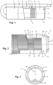
Figure 2 diagrammatically shows a sectional view of a vacuum cleaner unit according to an embodiment of the invention; -
Figure 3 diagrammatically shows a front view of the vacuum cleaner unit; -
Figure 4 diagrammatically shows a bottom view of the vacuum cleaner unit and illustrates how air spirals through the vacuum cleaner unit during operation; -
Figure 5 diagrammatically shows a side view of the vacuum cleaner unit and illustrates how air spirals through the vacuum cleaner unit during operation; and -
Figure 6 diagrammatically shows a corner rib that is part of the vacuum cleaner unit. - The invention is in the field of vacuum cleaning and vacuum cleaners, particularly vacuum cleaners comprising a vacuum cleaner unit that is designed to separate dirt and air. A basic configuration of a vacuum cleaner 1 that is of the handheld type is illustrated in
figure 1 . The vacuum cleaner 1 comprises aconduit 2, asuction nozzle 3 at an end of theconduit 2, avacuum cleaner unit 4 connected to theconduit 2, and anarrangement 5 configured to generate air suction forces at the position of thesuction nozzle 3 and an air flow from thesuction nozzle 3 towards thevacuum cleaner unit 4, through theconduit 2, whicharrangement 5 normally includes a suitable type of motor. The handheld vacuum cleaner 1 may be provided as a removable part of a larger vacuum cleaner such as a stick vacuum cleaner, but it is also possible that the handheld vacuum cleaner 1 is provided as a standalone device. Normally, a front side of the vacuum cleaner 1 is defined as the side where thesuction nozzle 3 is present and a back side of the vacuum cleaner 1 is defined as the side where thearrangement 5 including the motor is present. Infigure 1 , the vacuum cleaner 1 is shown in a generally horizontal orientation. For the purpose of cleaning floors and other surfaces that can be reached from above, the vacuum cleaner 1 is to be held in a downward orientation, i.e. an orientation with thesuction nozzle 3 pointing downwards, and for the purpose of cleaning ceilings and other surfaces that can be reached from below, the vacuum cleaner 1 is to be held in an upward orientation, i.e. an orientation with thesuction nozzle 3 pointing upwards. - Operating the handheld vacuum cleaner 1 involves putting the
arrangement 5 including the motor to an activated state, so that air suction forces are generated at the position of thesuction nozzle 3. When a person using the vacuum cleaner 1 holds the vacuum cleaner 1 in a position in which thesuction nozzle 3 is close to or on a surface to be cleaned, dirt is removed from the surface under the influence of the air suction forces, wherein the dirt is carried to inside thesuction nozzle 3 and theconduit 2, along with air. The dirt-laden air is made to move towards thevacuum cleaner unit 4 and is supplied to thevacuum cleaner unit 4 at the position of aninlet 6 of thevacuum cleaner unit 4. - As suggested in the foregoing, the
vacuum cleaner unit 4 is designed to separate dirt and air. To that end, thevacuum cleaner unit 4 is equipped with a cleanedair discharge arrangement 10 in the form of a hollow cylinder provided withslots 11. Further, two wall structures can be discerned in thevacuum cleaner unit 4, namely 1) afirst wall structure 12 defining anair swirling space 13 in thevacuum cleaner unit 4 surrounding the cleanedair discharge arrangement 10 in a direction about a longitudinal axis AL of the cleanedair discharge arrangement 10 defining a longitudinal direction in thevacuum cleaner unit 4, and 2) asecond wall structure 14 defining adirt space 15 in thevacuum cleaner unit 4. The above-mentionedinlet 6 of thevacuum cleaner unit 4 is particularly at a position for letting in dirt-laden air to theair swirling space 13. Further, the cleanedair discharge arrangement 10 is configured to discharge air from thevacuum cleaner unit 4, and thesecond wall structure 14 is configured to receive and store dirt of the dirt-laden air at the position of thedirt space 15. - During operation of the vacuum cleaner 1, an air swirling movement about the cleaned
air discharge arrangement 10 in theair swirling space 13 is promoted on the basis of a number of factors. In the first place, the dirt-laden air is let in tangentially to theair swirling space 13 at a side position on thevacuum cleaner unit 4, in the second place, thevacuum cleaner unit 4 is equipped with aguide part 16 that is arranged and shaped such that the incoming air is guided to follow a coil-shaped path, and in the third place, surfaces having a circular outline are generally present in thevacuum cleaner unit 4, as can best be seen infigure 3 . The spiraling movement of the air in thevacuum cleaner unit 4 is illustrated infigures 4 and 5 . As the air swirls about the cleanedair discharge arrangement 10, air passes to inside the cleanedair discharge arrangement 10 through theslots 11, while the dirt is displaced towards thedirt space 15 and is collected there. - As can be seen in the
figures 1, 2 ,4 and 5 , thesecond wall structure 14 is located in the extension of thefirst wall structure 12 so that thedirt space 15 is located further down the cleanedair discharge arrangement 10 and theair swirling space 13 in the longitudinal direction. Special features of thevacuum cleaner unit 4 aimed at optimizing the retention of dirt in thedirt space 15 in all possible orientations of the handheld vacuum cleaner 1 and avoiding accumulation on the cleanedair discharge arrangement 10 of any dirt reentering theair swirling space 13 are clearly visible infigures 2-5 . Infigure 6 , one of those special features is shown in enlarged fashion. A further explanation of those features is now provided. - In the present embodiment, the
vacuum cleaner unit 4 comprises anextension body 17 located in the extension of the cleanedair discharge arrangement 10, wherein in the longitudinal direction, an end of theextension body 17 at a side of theextension body 17 facing away from the cleanedair discharge arrangement 10 is at a distance from thesecond wall structure 14. In other words, theextension body 17 does not reach all the way down to thesecond wall structure 14. In the present example, the extension body is generally tube-shaped, having both a circular interior periphery and a circular exterior periphery. Theextension body 10 has a function in ensuring that a minimum of energy is present in the air at the position of thedirt space 15, so that a risk that dirt in thedirt space 15 is agitated by the air and thereby displaced from thedirt space 15 is minimized. - The
vacuum cleaner unit 4 also comprises atangential rib 18 projecting inwardly from thesecond wall structure 14 in a direction being a substantially radial direction relative to the longitudinal direction and extending in a direction being a substantially tangential direction relative to the longitudinal direction. In the present example, thetangential rib 18 is crescent-shaped and extends along an angular distance of less than 180° in the substantially tangential direction, as can best be seen infigure 3 . In the longitudinal direction, thetangential rib 18 is located at the position of the end of theextension body 17 at the side of theextension body 17 facing away from the cleanedair discharge arrangement 10. Like theextension body 17, thetangential rib 18 has a function in ensuring calmness of air in thedirt space 15, especially in the longitudinal direction. Infigures 4 and 5 , the spiral of the swirling air is diagrammatically shown, and it can be seen how the spiral intersects with thetangential rib 18. In reality, the spiral is not continuous but expands in the direction of thedirt space 15. At the intersection position as shown infigures 4 and 5 , the flow will bump smoothly against thetangential rib 18 and get deflected in such a way that the air volume at the other side of thetangential rib 18 remains calm. Further, thetangential rib 18 is at a position for preventing dirt from falling back to theair swirling space 13 when the vacuum cleaner 1 is in an upward orientation. - At a position that is between the cleaned
air discharge arrangement 10 and theextension body 17 in the longitudinal direction, aflow deflection element 19 shaped like an outwardly projecting rim is provided. Theflow deflection element 19 prevents any dirt traveling back from thedirt space 15 towards theair swirling space 13 from reaching an area of the cleanedair discharge arrangement 10 where there is hardly air movement about the cleanedair discharge arrangement 10, so that it is ensured that such dirt is always subjected to the dirt-air separation action again. - Finally, the
vacuum cleaner unit 4 comprises acorner rib 20 arranged on thesecond wall structure 14 in a substantially radial orientation relative to the longitudinal direction, at a position that is substantially diametrically opposed to the position of thetangential rib 18, as can best be seen infigure 3 . Thecorner rib 20 is located in thevacuum cleaner unit 4 at a position where aportion 14a of thesecond wall structure 14 extending in the longitudinal direction connects to a portion of thesecond wall structure 14 being anend portion 14b in the longitudinal direction. It is noted that it is practical if theend portion 14b is removable so as to enable easy emptying of thedirt space 15. Thecorner rib 20 has a function in further preventing air movement, particularly rotating air movement, in thedirt space 15, at the very position where the dirt is accumulated. Hence, thecorner rib 20 contributes to realizing undisturbed storage of the dirt in thedirt space 15. - The
corner rib 20 can be of any suitable shape. In the present example, thecorner rib 20 is plate-shaped, as can best be seen infigure 3 . Also, thecorner rib 20 has a generally bevelled appearance, as can best be seen infigures 2 ,5 and 6 . For example, thecorner rib 20 comprises both atriangular portion 21 and arectangular portion 22, as shown, wherein thecorner rib 20 is connected to theportion 14a of thesecond wall structure 14 extending in the longitudinal direction through thetriangular portion 21, and wherein thecorner rib 20 is connected to theend portion 14b of thesecond wall structure 14 through therectangular portion 22. - Practical examples of a number of the order of the dimensions in the
vacuum cleaner unit 4 include the following: diameter of the vacuum cleaner unit 4: 106 mm; volume of thedirt space 15 beyond the tangential rib 18: 250 ml; diameter of the cleanedair discharge arrangement 10 and the extension body 17: 65 mm; length of the extension body 17: 40 mm; wall thickness of the extension body 17: 2 mm; radial distance between the cleanedair discharge arrangement 10 and the first wall structure 12: 15 mm; radial dimension of the center part of the crescent-shaped tangential rib 18: 7.5 mm; wall thickness of the corner rib 20: 2 mm. Especially a larger dimensioning of thevacuum cleaner unit 4 is just as well feasible for practical applications of the invention. - It is to be noted that the fact that the present embodiment of the
vacuum cleaner unit 4 is provided with a combination of all of the four above-described special features, i.e. theextension body 17, thetangential rib 18, theflow deflection element 19 and thecorner rib 20, does not imply that such a combination is essential. Advantageous effects are obtained when at least one of the features is applied, so that options of applying one, two or three of the four special features are also feasible. In any case, by applying at least one of the special features, it is achieved that in the configuration in which thedirt space 15 is located further down the cleanedair discharge arrangement 10 and theair swirling space 13 in the longitudinal direction, dirt retention in thedirt space 15 and/or renewed separation of any fallback dirt from the air and subsequent renewed discharge of the dirt to thedirt space 15 are promoted. The special features are chosen such that flow behavior in thevacuum cleaner unit 4 is not hindered, or hindered to a minimal extent only, so that the separation performance of the cyclone unit is not or hardly deteriorated. All of the special features involve a relatively simple addition to the basic set-up of thevacuum cleaner unit 4 and can easily be manufactured. - It will be clear to a person skilled in the art that the scope of the invention is not limited to the examples discussed in the foregoing, but that several amendments and modifications thereof are possible without deviating from the scope of the invention as defined in the attached claims. It is intended that the invention be construed as including all such amendments and modifications insofar they come within the scope of the claims or the equivalents thereof. While the invention has been illustrated and described in detail in the figures and the description, such illustration and description are to be considered illustrative or exemplary only, and not restrictive. The invention is not limited to the disclosed embodiments. The drawings are schematic, wherein details that are not required for understanding the invention may have been omitted, and not necessarily to scale.
- Variations to the disclosed embodiments can be understood and effected by a person skilled in the art in practicing the claimed invention, from a study of the figures, the description and the attached claims. In the claims, the word "comprising" does not exclude other steps or elements, and the indefinite article "a" or "an" does not exclude a plurality. Any reference signs in the claims should not be construed as limiting the scope of the invention.
- Elements and aspects discussed for or in relation with a particular embodiment may be suitably combined with elements and aspects of other embodiments, unless explicitly stated otherwise. Thus, the mere fact that certain measures are recited in mutually different dependent claims does not indicate that a combination of these measures cannot be used to advantage.
- The terms "comprise" and "include" as used in this text will be understood by a person skilled in the art as covering the term "consist of". Hence, the term "comprise" or "include" may in respect of an embodiment mean "consist of", but may in another embodiment mean "contain/have/be equipped with at least the defined species and optionally one or more other species".
- Notable aspects of the invention are summarized as follows. In a
vacuum cleaner unit 4 comprising a a cleanedair discharge arrangement 10, anair swirling space 13 surrounding the cleanedair discharge arrangement 10, and adirt space 15 that is at a position further down the cleanedair discharge arrangement 10 and theair swirling space 13, one or more special features are present to promote dirt retention in thedirt space 15 and/or renewed separation of any fallback dirt from the air and subsequent renewed discharge of the dirt to thedirt space 15. The special features are anextension body 17 located in the extension of the cleanedair discharge arrangement 10, aflow deflection element 19 for preventing fallback dirt from reaching an area where the air is practically stationary, atangential rib 18 on awall structure 14 defining thedirt space 15, and acorner rib 20 on saidwall structure 14.
Claims (15)
- Vacuum cleaner unit (4) configured to be used in a vacuum cleaner (1) and to receive incoming dirt-laden air in the vacuum cleaner (1) and to bring about separation of dirt and air, the vacuum cleaner unit (4) comprising:- a cleaned air discharge arrangement (10);- a first wall structure (12) defining an air swirling space (13) in the vacuum cleaner unit (4) surrounding the cleaned air discharge arrangement (10) in a direction about a longitudinal axis (AL) of the cleaned air discharge arrangement (10) defining a longitudinal direction in the vacuum cleaner unit (4);- at least one inlet (6) configured to let in dirt-laden air to the air swirling space (13); and- a second wall structure (14) defining a dirt space (15) in the vacuum cleaner unit (4);wherein the cleaned air discharge arrangement (10) is configured to discharge air from the vacuum cleaner unit (4);wherein the second wall structure (14) is configured to receive and store dirt of the dirt-laden air at the position of the dirt space (15);wherein the second wall structure (14) is located in the extension of the first wall structure (12); andwherein the vacuum cleaner unit (4) further comprises at least one of the following:- a flow deflection element (19) located at a position that is between the air swirling space (13) and the dirt space (15) in the longitudinal direction, of which at least a portion projects outwardly relative to the cleaned air discharge arrangement (10) in a direction being a substantially radial direction relative to the longitudinal direction;- an extension body (17) located in the extension of the cleaned air discharge arrangement (10), wherein in the longitudinal direction, an end of the extension body (17) at a side of the extension body (17) facing away from the cleaned air discharge arrangement (10) is at a distance from the second wall structure (14);- a tangential rib (18) projecting inwardly from the second wall structure (14) in the substantially radial direction and extending in a direction being a substantially tangential direction relative to the longitudinal direction; and- a corner rib (20) arranged on the second wall structure (14) in a substantially radial orientation relative to the longitudinal direction, at a position where a portion (14a) of the second wall structure (14) extending in the longitudinal direction connects to a portion of the second wall structure (14) being an end portion (14b) in the longitudinal direction.
- Vacuum cleaner unit (4) as claimed in claim 1, wherein the extension body (17) is generally tube-shaped, having both a circular interior periphery and a circular exterior periphery.
- Vacuum cleaner unit (4) as claimed in claim 1 or 2, wherein the tangential rib (18) extends along an angular distance of less than 360° in the substantially tangential direction, preferably along an angular distance of at most 180° in the substantially tangential direction.
- Vacuum cleaner unit (4) as claimed in any of claims 1-3, wherein the tangential rib (18) is crescent-shaped.
- Vacuum cleaner unit (4) as claimed in any of claims 1-4, comprising both the extension body (17) and the tangential rib (18).
- Vacuum cleaner unit (4) as claimed in claim 5, wherein in the longitudinal direction, a position of the tangential rib (18) substantially corresponds to a position of the end of the extension body (17) at the side of the extension body (17) facing away from the cleaned air discharge arrangement (10).
- Vacuum cleaner unit (4) as claimed in claim 5 or 6, wherein in the substantially radial direction, the tangential rib (18) extends from the second wall structure (14) to cover half or less of a distance between the second wall structure (14) and the extension body (17).
- Vacuum cleaner unit (4) as claimed in any of claims 1-7, comprising both the flow deflection element (19) and the extension body (17), and wherein the flow deflection element (19) and the extension body (17) are integrated in a single component.
- Vacuum cleaner unit (4) as claimed in any of claims 1-4, wherein in the longitudinal direction, a position of the tangential rib (18) substantially corresponds to a position of an end of the cleaned air discharge arrangement (10).
- Vacuum cleaner unit (4) as claimed in any of claims 1-9, wherein the corner rib (20) is plate-shaped and has a generally beveled appearance.
- Vacuum cleaner unit (4) as claimed in any of claims 1-10, wherein the corner rib (20) is plate-shaped and comprises both a triangular portion (21) and a rectangular portion (22), wherein the corner rib (20) is connected to the portion (14a) of the second wall structure (14) extending in the longitudinal direction through the triangular portion (21), and wherein the corner rib (20) is connected to the end portion (14b) of the second wall structure (14) through the rectangular portion (22).
- Vacuum cleaner unit (4) as claimed in any of claims 1-11, comprising both the tangential rib (18) and the corner rib (20), wherein the tangential rib (18) and the corner rib (20) are at substantially diametrically opposed positions.
- Vacuum cleaner unit (4) as claimed in any of claims 1-12, wherein the first wall structure (12) and the portion (14a) of the second wall structure (14) extending in the longitudinal direction are integrated in a single component.
- Vacuum cleaner (1), comprising a conduit (2), a suction nozzle (3) at an end of the conduit (2), a vacuum cleaner unit (4) as claimed in any of claims 1-13 connected to the conduit (3), and an arrangement (5) configured to generate air suction forces at the position of the suction nozzle (3) and an air flow from the suction nozzle (3) towards the vacuum cleaner unit (4), through the conduit (2).
- Vacuum cleaner (1) as claimed in claim 14, being of the handheld type.
Priority Applications (6)
| Application Number | Priority Date | Filing Date | Title |
|---|---|---|---|
| EP23181745.3A EP4483765A1 (en) | 2023-06-27 | 2023-06-27 | Vacuum cleaner unit including an air swirling space and a dirt space |
| AU2024306660A AU2024306660A1 (en) | 2023-06-27 | 2024-06-07 | Vacuum cleaner unit including an air swirling space and a dirt space |
| KR1020267002370A KR20260028098A (en) | 2023-06-27 | 2024-06-07 | Vacuum cleaner unit including air vortex space and dust space |
| CN202480042981.8A CN121463903A (en) | 2023-06-27 | 2024-06-07 | Vacuum cleaner unit comprising an air swirling space and a dust space |
| PCT/EP2024/065784 WO2025002762A1 (en) | 2023-06-27 | 2024-06-07 | Vacuum cleaner unit including an air swirling space and a dirt space |
| EP24731355.4A EP4734807A1 (en) | 2023-06-27 | 2024-06-07 | Vacuum cleaner unit including an air swirling space and a dirt space |
Applications Claiming Priority (1)
| Application Number | Priority Date | Filing Date | Title |
|---|---|---|---|
| EP23181745.3A EP4483765A1 (en) | 2023-06-27 | 2023-06-27 | Vacuum cleaner unit including an air swirling space and a dirt space |
Publications (1)
| Publication Number | Publication Date |
|---|---|
| EP4483765A1 true EP4483765A1 (en) | 2025-01-01 |
Family
ID=87003099
Family Applications (2)
| Application Number | Title | Priority Date | Filing Date |
|---|---|---|---|
| EP23181745.3A Withdrawn EP4483765A1 (en) | 2023-06-27 | 2023-06-27 | Vacuum cleaner unit including an air swirling space and a dirt space |
| EP24731355.4A Pending EP4734807A1 (en) | 2023-06-27 | 2024-06-07 | Vacuum cleaner unit including an air swirling space and a dirt space |
Family Applications After (1)
| Application Number | Title | Priority Date | Filing Date |
|---|---|---|---|
| EP24731355.4A Pending EP4734807A1 (en) | 2023-06-27 | 2024-06-07 | Vacuum cleaner unit including an air swirling space and a dirt space |
Country Status (5)
| Country | Link |
|---|---|
| EP (2) | EP4483765A1 (en) |
| KR (1) | KR20260028098A (en) |
| CN (1) | CN121463903A (en) |
| AU (1) | AU2024306660A1 (en) |
| WO (1) | WO2025002762A1 (en) |
Citations (3)
| Publication number | Priority date | Publication date | Assignee | Title |
|---|---|---|---|---|
| EP3488749A1 (en) * | 2017-11-24 | 2019-05-29 | Seb S.A. | Hand-held bagless vacuum cleaner provided with a removable bowl |
| US20190200824A1 (en) * | 2017-12-30 | 2019-07-04 | Dyson Technology Limited | Dirt separator |
| WO2022002591A1 (en) | 2020-06-29 | 2022-01-06 | Koninklijke Philips N.V. | Vacuum cleaner |
-
2023
- 2023-06-27 EP EP23181745.3A patent/EP4483765A1/en not_active Withdrawn
-
2024
- 2024-06-07 CN CN202480042981.8A patent/CN121463903A/en active Pending
- 2024-06-07 WO PCT/EP2024/065784 patent/WO2025002762A1/en not_active Ceased
- 2024-06-07 AU AU2024306660A patent/AU2024306660A1/en active Pending
- 2024-06-07 KR KR1020267002370A patent/KR20260028098A/en active Pending
- 2024-06-07 EP EP24731355.4A patent/EP4734807A1/en active Pending
Patent Citations (3)
| Publication number | Priority date | Publication date | Assignee | Title |
|---|---|---|---|---|
| EP3488749A1 (en) * | 2017-11-24 | 2019-05-29 | Seb S.A. | Hand-held bagless vacuum cleaner provided with a removable bowl |
| US20190200824A1 (en) * | 2017-12-30 | 2019-07-04 | Dyson Technology Limited | Dirt separator |
| WO2022002591A1 (en) | 2020-06-29 | 2022-01-06 | Koninklijke Philips N.V. | Vacuum cleaner |
Also Published As
| Publication number | Publication date |
|---|---|
| CN121463903A (en) | 2026-02-03 |
| WO2025002762A1 (en) | 2025-01-02 |
| EP4734807A1 (en) | 2026-05-06 |
| KR20260028098A (en) | 2026-03-03 |
| AU2024306660A1 (en) | 2026-02-12 |
Similar Documents
| Publication | Publication Date | Title |
|---|---|---|
| EP2452604B1 (en) | Cyclone dust collecting apparatus and vacuum cleaner having the same | |
| CN101449948B (en) | Cyclone system for dust collector and dust collector with the same | |
| ES2251865B2 (en) | ASSEMBLY ASSEMBLY SET FOR VACUUM CLEANER AND POWDER COLLECTOR. | |
| CN102772174B (en) | Surface treating appliance | |
| US7655058B2 (en) | Cyclonic vacuum cleaner | |
| EP2617281B1 (en) | Apparatus for collection of garden waste | |
| CN102772176B (en) | Surface treating appliance | |
| EP2696737B1 (en) | Cyclonic separator with shroud comprising an inlet opening and exit perforations | |
| CN102772173B (en) | Surface treating appliance | |
| CN102772179B (en) | Surface treatment device | |
| EP2696734B1 (en) | Cyclonic separator | |
| US8869346B2 (en) | Vacuum cleaner having cyclone dust collecting apparatus | |
| US20030131440A1 (en) | Cannister and upright vortex vacuum cleaners | |
| KR20100084127A (en) | Cyclonic separation device with acceleration ramp | |
| US7662202B2 (en) | Dust collector of vacuum cleaner | |
| WO2002003846A1 (en) | Improved air-particle separator | |
| CN215959591U (en) | Vacuum cleaner with a vacuum cleaner head | |
| EP1938734A2 (en) | Dust collecting apparatus for vacuum cleaner | |
| CN115052507A (en) | Wet type vacuum cleaner | |
| US20050194295A1 (en) | Air/particle separator | |
| GB2367512A (en) | Multiple cyclone separation unit | |
| WO2025002762A1 (en) | Vacuum cleaner unit including an air swirling space and a dirt space | |
| JP5824640B2 (en) | Electric vacuum cleaner | |
| WO2012104754A1 (en) | Device for separating particles from air, comprising a vortex chamber | |
| WO2025036909A1 (en) | Preventing electrostatic buildup at a surface of a core part of a vacuum cleaner unit |
Legal Events
| Date | Code | Title | Description |
|---|---|---|---|
| PUAI | Public reference made under article 153(3) epc to a published international application that has entered the european phase |
Free format text: ORIGINAL CODE: 0009012 |
|
| STAA | Information on the status of an ep patent application or granted ep patent |
Free format text: STATUS: THE APPLICATION HAS BEEN PUBLISHED |
|
| AK | Designated contracting states |
Kind code of ref document: A1 Designated state(s): AL AT BE BG CH CY CZ DE DK EE ES FI FR GB GR HR HU IE IS IT LI LT LU LV MC ME MK MT NL NO PL PT RO RS SE SI SK SM TR |
|
| STAA | Information on the status of an ep patent application or granted ep patent |
Free format text: STATUS: THE APPLICATION IS DEEMED TO BE WITHDRAWN |
|
| 18D | Application deemed to be withdrawn |
Effective date: 20250702 |