EP3488749A1 - Hand-held bagless vacuum cleaner provided with a removable bowl - Google Patents
Hand-held bagless vacuum cleaner provided with a removable bowl Download PDFInfo
- Publication number
- EP3488749A1 EP3488749A1 EP18207902.0A EP18207902A EP3488749A1 EP 3488749 A1 EP3488749 A1 EP 3488749A1 EP 18207902 A EP18207902 A EP 18207902A EP 3488749 A1 EP3488749 A1 EP 3488749A1
- Authority
- EP
- European Patent Office
- Prior art keywords
- bowl
- vacuum cleaner
- tube
- locking system
- suction
- Prior art date
- Legal status (The legal status is an assumption and is not a legal conclusion. Google has not performed a legal analysis and makes no representation as to the accuracy of the status listed.)
- Granted
Links
- 238000000926 separation method Methods 0.000 claims abstract description 3
- 230000005540 biological transmission Effects 0.000 claims description 7
- 238000007789 sealing Methods 0.000 claims description 3
- 210000000056 organ Anatomy 0.000 claims 1
- 238000004140 cleaning Methods 0.000 description 15
- 239000012535 impurity Substances 0.000 description 13
- 208000031968 Cadaver Diseases 0.000 description 8
- 230000015572 biosynthetic process Effects 0.000 description 5
- 230000001680 brushing effect Effects 0.000 description 5
- 238000012423 maintenance Methods 0.000 description 4
- 238000001914 filtration Methods 0.000 description 3
- 238000000605 extraction Methods 0.000 description 2
- 230000035939 shock Effects 0.000 description 2
- 230000003213 activating effect Effects 0.000 description 1
- 230000004913 activation Effects 0.000 description 1
- 230000000295 complement effect Effects 0.000 description 1
- 230000006835 compression Effects 0.000 description 1
- 238000007906 compression Methods 0.000 description 1
- 230000000694 effects Effects 0.000 description 1
- 239000010419 fine particle Substances 0.000 description 1
- 238000003780 insertion Methods 0.000 description 1
- 230000037431 insertion Effects 0.000 description 1
- 238000009434 installation Methods 0.000 description 1
- 230000014759 maintenance of location Effects 0.000 description 1
- 239000012780 transparent material Substances 0.000 description 1
Images


Classifications
-
- A—HUMAN NECESSITIES
- A47—FURNITURE; DOMESTIC ARTICLES OR APPLIANCES; COFFEE MILLS; SPICE MILLS; SUCTION CLEANERS IN GENERAL
- A47L—DOMESTIC WASHING OR CLEANING; SUCTION CLEANERS IN GENERAL
- A47L5/00—Structural features of suction cleaners
- A47L5/12—Structural features of suction cleaners with power-driven air-pumps or air-compressors, e.g. driven by motor vehicle engine vacuum
- A47L5/22—Structural features of suction cleaners with power-driven air-pumps or air-compressors, e.g. driven by motor vehicle engine vacuum with rotary fans
- A47L5/24—Hand-supported suction cleaners
-
- A—HUMAN NECESSITIES
- A47—FURNITURE; DOMESTIC ARTICLES OR APPLIANCES; COFFEE MILLS; SPICE MILLS; SUCTION CLEANERS IN GENERAL
- A47L—DOMESTIC WASHING OR CLEANING; SUCTION CLEANERS IN GENERAL
- A47L9/00—Details or accessories of suction cleaners, e.g. mechanical means for controlling the suction or for effecting pulsating action; Storing devices specially adapted to suction cleaners or parts thereof; Carrying-vehicles specially adapted for suction cleaners
- A47L9/10—Filters; Dust separators; Dust removal; Automatic exchange of filters
- A47L9/16—Arrangement or disposition of cyclones or other devices with centrifugal action
- A47L9/1683—Dust collecting chambers; Dust collecting receptacles
-
- A—HUMAN NECESSITIES
- A47—FURNITURE; DOMESTIC ARTICLES OR APPLIANCES; COFFEE MILLS; SPICE MILLS; SUCTION CLEANERS IN GENERAL
- A47L—DOMESTIC WASHING OR CLEANING; SUCTION CLEANERS IN GENERAL
- A47L9/00—Details or accessories of suction cleaners, e.g. mechanical means for controlling the suction or for effecting pulsating action; Storing devices specially adapted to suction cleaners or parts thereof; Carrying-vehicles specially adapted for suction cleaners
- A47L9/10—Filters; Dust separators; Dust removal; Automatic exchange of filters
- A47L9/16—Arrangement or disposition of cyclones or other devices with centrifugal action
- A47L9/1691—Mounting or coupling means for cyclonic chamber or dust receptacles
Definitions
- the present invention relates to the field of cleaning apparatus and, more particularly, to a bagless hand vacuum, otherwise known as a cyclonic hand aspirator.
- Such a vacuum cleaner is intended to be compact and carried with a hand to suck low surfaces, such as a worktop or stairs, or raised surfaces, for example a ceiling or a wall or furniture arranged in height.
- Bagless hand vacuums are known to those skilled in the art.
- Such an aspirator comprises a body which is provided at the rear with a handle and which incorporates suction means.
- the vacuum cleaner also comprises a suction tube through the front end which is sucked impurities and a filter chamber arranged between the suction tube and the suction means on the body for receiving and temporarily store the impurities sucked.
- the filtration chamber comprises a bowl which communicates with the suction tube and a filter element which is housed in the bowl and which communicates with the suction means.
- the air flow When activating the suction means, the air flow generates a vacuum to suck the impurities by the front end of the suction tube; the impure air flow circulates in said tube and then enters the bowl where the impurities are largely trapped by a centrifugal force generated in this bowl, while the filter element disposed downstream (taking into account the direction of circulation of the air flow) makes it possible to retain the fine particles of impurities, the stream of filtered air then continuing its circuit in the body under the action of said suction means, to be finally rejected from said body, by example at the back of it.
- the suction tube is integrated in the bowl, the assembly being assembled with the body.
- the bowl comprises in the lower part a hatch whose opening is effected by means of a remote control, the opening of the hatch to empty the bowl.
- This remote control is configured to concomitantly extract the filter element from above the bowl, to ensure regular cleaning of the filter element at each bowl emptying.
- the tube, bowl and filter element assembly is removable from the body to allow complete cleaning of the bowl, the extraction of the assembly being carried out thanks to the remote control.
- the suction tube is integrated into the bowl, the assembly being removable from the body.
- assembly means are implemented between a rear face of the bowl and a front face of the body.
- the rear and the front are defined respectively opposite the positions of the handle and the suction tube on the vacuum cleaner.
- the bowl comprises in the lower part a hatch.
- the body comprises a control member for unlocking the assembly means to extract the bowl and allow cleaning of the filter element. This control member also allows the opening of the hatch for emptying the bowl.
- the present invention has for first objective to implement a hand-held vacuum cleaner with an extractable bowl to allow its emptying and cleaning, and the cleaning of the filter element, the assembly means of the bowl on the body being optimized to facilitate the handling of said bowl during its establishment on the body and during its withdrawal from said body.
- these bowl assembly means on the body provide a suitable attachment between these two elements so that the detachment of the bowl can not occur in case of shocks to it caused during the operation of the vacuum cleaner.
- Another objective is to optimize the suction of impurities by ensuring a very good seal when assembling the bowl on the body.
- Another objective is to facilitate the handling of the bowl during its emptying or cleaning and that of the filter element inserted in the bowl.
- Another objective is to promote regular cleaning of the bowl and the filter element.
- Another objective is to facilitate the handling of the vacuum cleaner in all situations of use, that is to say as well when it comes to vacuuming surfaces on the ground that when it comes to Aspirate raised surfaces.
- the invention relates to a hand-held vacuum cleaner, called “vacuum cleaner” in the following description.
- the vacuum cleaner comprises a body provided with a gripping handle arranged at the rear of the vacuum cleaner and suction means, a suction tube arranged at the front of the vacuum cleaner and a suction chamber provided with a bowl communicating with the suction tube, and a filter element inserted into the bowl and which communicates with the suction means.
- a hand vacuum does not include a bag, the bowl directly for the storage of impurities sucked.
- Such a vacuum cleaner is frequently called cyclonic hand aspirator and can generate a centrifugal force in the bowl during suction, which ensures the removal of a large part of the impurities in the bottom of the bowl; the operating principle during the activation of the suction means is described above and applies to the present case of the invention.
- the vacuum cleaner comprises a guiding and holding system arranged between a rear face of the bowl and a front face of the body to engage the bowl on the body until reaching a position of formation of the suction chamber or, conversely, to clear the bowl of the body until a separation position.
- This guidance and maintenance system is configured to accompany the movement of the bowl on the body during engagement or release. It is understood that the terms “back” and “front” are appreciated in relation to the position of the handle, arranged at the rear of the vacuum cleaner, and the suction tube, arranged at the front of the vacuum.
- the vacuum cleaner comprises a locking system arranged between a front upper portion of the bowl and a front portion of the body for locking the bowl on the body in the suction chamber forming position or to unlock the bowl of the body so as to clear it.
- the design of the vacuum cleaner according to the invention allows a convenient and accurate positioning, intuitively, the bowl on the body for the formation of the suction chamber.
- the user positions the portion of the guiding and holding system on the bowl in correspondence with that on the body, then engages the bowl on the body by pushing it, which moves it naturally or intuitively thanks to the guiding and holding system until reaching the forming position of the suction chamber where the locking system is engaged to maintain said position, the bowl being precisely positioned on the body.
- the position of the guiding and holding system, at the rear of the bowl, and that of the locking system, at the front of the bowl, ensure a proper distribution of the efforts between the bowl and the body, which reduces the risks of disassembly of the bowl in case of shock of the vacuum cleaner on obstacles during cleaning.
- the user unlocks the bowl from the body and then intuitively releases the bowl from the body by pulling it until it is completely removed, the bowl's movement towards the body being imposed by the system. guidance and maintenance.
- the guiding and holding system is configured to engage the bowl on the body by pushing it backwards on the body or, conversely, upon its release from the body by pulling it forward on the body. body. It is understood that a multitude of trajectories of the bowl on the body is possible during its engagement and during its release, each of these trajectories that require pushing backwards or pulling the bowl forward on the body for movement to occur.
- the guiding and holding system is arranged in the lower part of the rear face of the bowl and in the lower part of the front face of the body. This further optimizes the distribution of effort between the bowl and the body, for a better maintenance of the bowl assembled on the body.
- the guiding and holding system comprises a cam arranged on the rear face of the bowl and a cam track arranged on the front face of the body.
- the cam is arranged in the lower part of the rear face of the bowl and the cam path is arranged in the lower part of the front face of the body.
- the cam and the cam path are configured to engage the bowl on the body by performing a translational movement followed by a rotational movement, and conversely when the bowl is disengaged from the body.
- the rotation is performed on an angle of the order of forty degrees (40 °) to fifty degrees (50 °), preferably forty-five degrees (45 °).
- the translational movement essentially serves to engage the cam in the cam path.
- the latter comprises at least one bolt arranged on the bowl and at least one keeper arranged on the body.
- the locking system comprises a control member arranged on the bowl and transmission means arranged between the control member and the at least one bolt to disengage the latch bolt when actuating the latch. control member.
- the presence of the control member on the bowl advantageously allows to have directly in hand the bowl during unlocking, while the body is held by its handle with the other hand.
- the locking system comprises a return element for bringing the at least one bolt into position engaged in the at least one strike, each bolt comprising an inclined face configured to retract said bolt in contact with the striker at the end of movement when engaging the bowl on the body. This locks automatically bowl on the body once the bowl set up.
- the locking system comprises two bolts engaging respectively in two strikes, the bolts being positioned in opposition and moving laterally, each on one side of the vacuum cleaner.
- the locking system comprises a hook configured to be housed on an edge of the body and ensure the locking of the bowl in position on the body.
- the locking system comprises a control member arranged on the bowl and a transmission element arranged between the control member and the hook to disengage said hook from the edge of the body.
- the presence of the control member on the bowl advantageously allows to have directly in hand the bowl during unlocking, while the body is held by its handle with the other hand.
- the locking system comprises a return element for bringing the hook into position engaged in the edge of the body, the hook comprising a bent portion provided with an inclined face configured to retract said hook in contact with said edge at the end of movement when the bowl is engaged on the body. This automatically locks the bowl on the body once the bowl is in place.
- the tube is integrated in the body, in front of it.
- the bowl comprises a main opening through which is inserted the filter element and a secondary opening which communicates with the tube.
- the locking system is arranged at a junction zone between the body and the tube. It is understood that, since the tube is integrated into the body and forms a one-piece assembly, the front portion of the body merges with the rear portion of the tube.
- sealing means are implemented between a rear end of the tube and a front upper portion of the bowl and between the body and a rear upper portion of the bowl, the seal being placed in place during the formation of the chamber suction. Thanks to the guiding and holding system and the locking system, which ensure precise positioning of the bowl on the body during the formation of the suction chamber, it is ensured in each case that the seal is properly positioned between the bowl and body and between the bowl and the tube. This optimizes the tightness and the vacuum generated at the outlet of the tube during the flow of air flow.
- the bowl comprises on its front face a second handle.
- This second handle makes it possible to properly handle the bowl once extracted. This also allows a better grip of the vacuum cleaner when cleaning raised surfaces; the user can seize with one hand the first handle on the back of the vacuum cleaner and grasp with the other hand the second handle on the front of the vacuum cleaner.
- the filter element is inserted into the bowl removably.
- the filter element When removing the bowl for emptying, the filter element must be removed from the bowl, which makes it easier for the user to clean the filter element at the same time as it empties or cleans the bowl.
- the bowl is in a transparent material, which makes it easy to visualize the state of filling of the bowl and the fouling of the filter element.
- the bagless hand vacuum object of the invention will be called vacuum cleaner.
- the same references will be used to designate the same characteristics according to the various variants, unless otherwise indicated.
- the vacuum cleaner 1 comprises a body 2 which comprises a rear portion 2a and a front portion 2b.
- the rear part 2a comprises a first handle 4 which the user can grip with the hand to handle the vacuum cleaner 1.
- the first handle 4 is arranged in the lower part 1a of the vacuum cleaner 1.
- the vacuum cleaner 1 is electrically powered by means of a rechargeable battery (not shown) disposed in a base 5 which is assembled with the body 2 under the first gripping handle 4.
- the vacuum cleaner 1 comprises a tube 6 at the front end 6a from which impurities are sucked. This aspiration is provided by a flow of air which generates a vacuum at the front end 6a of the tube 6.
- the rear portion 2a of the body comprises a zone 7 in which is housed a fan (not illustrated) powered by the battery and which can generate said flow of air flowing from the front to the rear of the vacuum cleaner 1.
- the fan is disposed in the upper part 1b of the vacuum cleaner 1, just like the front part 2b of the body 2 which is arranged in the extension of the fan.
- the body 2 and the tube 6 form a one-piece assembly.
- the tube 6 is disposed in the front extension of the front portion 2b of the body 2.
- the front portion 2b of the body 2 comprises a duct 8 whose rear end 8a communicates with the zone 7 receiving the fan (not shown) and whose 8b front end opens on a lower face 2c of the body 2.
- the tube 6 comprises a conduit 9 which is separate from the conduit 8 on the body 2, although these two elements (body 2 and tube 6) form a one-piece assembly.
- the duct 9 of the tube 6 opens onto a rear opening 10, at the rear end 6b of the tube 6, and on a front opening 11, at the front end 6a of the tube 6.
- a brushing part 12 is attached from detachably on the front end 6a of the tube 6 by means of latching / unlocking means 13 provided between said brushing part 12 and the tube 6 on both lateral sides of the vacuum cleaner 1.
- latching / unclipping means 13 are preferably constituted by lugs 14 on the brushing part 12 which engage in lugs 15 on the tube 6.
- an extension tube (not shown) between the front end 6a of the tube 6 and the brushing part 12, said extension tube comprising on each of its lateral sides, at its rear end, a pin similar to the pin 14 for its engagement on the front end 6a of the tube 6 and , at its front end, a tab similar to the lug 15 for receiving the brushing part 12.
- the vacuum cleaner 1 comprises a bowl 17 which can be engaged on the body 2 to form a suction chamber 18 or, conversely, clear of the body 2 for its emptying and cleaning.
- the movements of the bowl 17 vis-à-vis the body 2, during its positioning and its extraction, are defined by the presence of a guiding and holding system 19 arranged between a rear face 17a of the bowl 17 and a front face 2d of the body 2.
- this guidance and holding system 19 comprises a cam 20 arranged in the lower part of the rear face 17a of the bowl 17 and a cam path 21 arranged in the lower part of the front face 2d of the body 2.
- the bowl 17 comprises on its front face 17b a second handle 22 facilitating its handling during its positioning and its removal vis-à-vis the body 2.
- This second handle 22 also facilitates the handling of the bowl 17 during its emptying.
- the user can grip with one hand this second handle 22 at the front of the vacuum cleaner 1 and, with the other hand, the first grip handle 4 at the rear of the body 2, which greatly facilitates the handling of the vacuum cleaner 1 when cleaning raised surfaces requiring lifting arms.
- the bowl 17 comprises on its upper rear part 17c a main opening 23 and on its upper front part 17d a secondary opening 24.
- the main opening 23 allows the insertion of a filter element 25 composed of two parts, namely a separator 26 and a filter 27.
- the separator 26 makes it possible to pass only the small-caliber impurities and the filter 27 makes it possible to block these small-sized impurities in order to let only the purified air pass.
- the separator 26 is housed in the bowl 17 and comprises an outer edge 26a which bears on the upper edge 28 delimiting the main opening 23, a first seal 29 positioned under the outer edge 26a sealing between the separator 26 and the bowl 17.
- the filter 27 is housed in the separator 26.
- the filter 27 comprises a lid 30 which bears on an inner edge 26b of the separator 26.
- a second seal 31 is arranged under the lid 30 and comes into contact with said inner edge 26b, which ensures the seal between the separator 26 and the filter 27.
- a third seal 32 is arranged on the lower face 2c of the body 2 and bears against the cover 30 of the filter 27 when locking the bowl 17 on the body 2, which ensures the seal between the body 2 and the filter 27.
- the cover 30 comprises in its center an opening 33 which communicates with a filter wall 34 of conical shape extending under the cover 30, the porosity of this filtering wall 34 making it possible to block the fine impurities and to let only the purified air pass through.
- the opening 33 communicates with the front end 8b of the duct 8 on the body 2, when the bowl 17 is in the assembled position.
- the separator 26 comprises a perforated wall 35 of cylindrical or conical shape which passes only the fine impurities, the filtering wall 34 being housed in the perforated wall 35.
- a fourth seal 36 is arranged around the rear opening 10 on the tube 6 and bears on the contour 37 of the secondary opening 24 during the locking of the bowl 17 on the body 2.
- the cam 20 and the cam path 21 are complementary and have a more or less bent shape.
- This bent shape is configured to engage the bowl 17 on the body 2, first by tilting the bowl 17 forward and downwardly relative to the body 2 by an angle of the order of forty degrees (40 °). ) at fifty degrees (50 °), preferably forty-five degrees (45 °), then slightly translating the bowl 17 rearwardly with respect to the body 2 so as to engage the rear end 20a of the cam 20 in the front end 21a of the cam path 21 (see Figures 3 and 4 ) and then pivoting the bowl 17 towards the body 2 backwards and upwards until the rear face 17a of the bowl 17 bears against the front face 2d of the body 2 (see FIG.
- the vacuum cleaner 1 further comprises a locking system 38 which is implemented between the upper front 17d of the bowl 17 and the front portion 2b of the body 2, more or less in a junction zone 39 between said body 2 and the tube 6 forming a unitary assembly.
- the assembly system 38 is deported under the tube 6 in this junction zone 39, which is made possible because the body 2 and the tube 6 form a one-piece assembly, the front portion 2b of the body 2 coinciding with the rear part of the tube 6.
- This locking system 38 comprises a control member 40 which is arranged in front of the upper end 22a of the second handle 22 on the bowl 17.
- the control member 40 has in its upper part a tab of transmission 41 which comprises two slots 42, 43 for transmitting a movement to two bolts 44, 45 to move them in translation according to the arrows 46, 47 when pressing the control member 40.
- This movement clears the bolts 44, 45 of the latches 48, 49 formed on the front portion 2b of the body 2 by two lugs 48a, 49a each provided with a hole 48b, 49b for receiving the bolts 44, 45.
- a first spring 50 arranged between the control member 40 and the second gripping handle 22 and a second spring 51 arranged between the two bolts 44, 45 allow automatic return of said control member 40 in the normal position and the two bolts 44, 45 in the engaged position in the latches s 48, 49.
- the bolts 44, 45 each comprise on their rear side an inclined section 44a (only that of the bolt 44 is illustrated) which is supported on the front edges 52, 53 of the tabs 48a, 49a at the end of the engagement.
- bowl 17 on the body 2 see Figures 7 and 8 ), which allows to automatically retract the bolts 44, 45 until they resume their normal position in the locks 48, 49 under the effect of the second spring 51, once they correspond with the orifices 48b, 49b (see figure 8 ).
- the locking is done automatically at the end of engagement during the formation of the compression chamber 18 and that the unlocking caused by the actuation of the control member 40 allows the clearance of the bowl 17 for its emptying and cleaning it, as well as cleaning the separator 26 and the filter 27.
- the control member 40 is actuated, the bowl 17 is positioned naturally in the position of the figure 6 thanks to the presence of the third seal 32 on the lower face 2c of the body 2 which exerts a thrust on the cover 30 of the filter 27.
- FIG. 14 A second variant of the locking system 38 is illustrated in Figures 14 and 15 .
- This variant comprises a control member 40 which may be similar to that previously described.
- This control member 40 is however subject to a hook 54 whose curved end 55 engages in an edge 56 arranged in the junction zone 39, as shown in FIG. figure 14 , which ensures the locking of the bowl 17 on the body 2 when the suction chamber 18 is formed.
- the locking of the curved end 55 in the edge 56 is done automatically at the end of engagement of the bowl 17 on the body 2.
- the curved end 55 comprises an inclined portion 57 bearing on an inclined face 58 s extending forwardly below the edge 56.
- a spring (not shown) similar to the first spring 50 allows the return of the control member 40, as before. It is understood that, according to this variant, the transmission of the movement to the hook 54 is provided directly by the control member 40; however, an additional transmission element could be provided between the control member 40 and the hook 54.
- Variations of the guiding and holding system 19 may in particular be envisaged by modifying the shape of the cam 20 and the cam path 21, which will substantially modify the trajectory of the bowl 17 vis-à-vis the body 2 during its engagement or its release.
Abstract
L'invention concerne un aspirateur (1) à main sans sac comprenant un corps (2), un tube (6) agencé à l'avant de l'aspirateur et une chambre d'aspiration (18) muni d'un bol (17) qui communique avec le tube et d'un élément filtrant (25) qui est inséré dans le bol et communique avec des moyens d'aspiration. L'aspirateur comprend un système de guidage et de maintien (19) agencé entre une face arrière (17a) du bol et une face avant (2d) du corps pour engager le bol sur le corps jusqu'à atteindre une position de formation de ladite chambre d'aspiration ou, inversement, dégager le bol du corps jusqu'à atteindre une position de séparation, ledit système de guidage et de maintien étant configuré pour accompagner le mouvement du bol sur le corps durant son engagement ou son dégagement. L'aspirateur comprend un système de verrouillage (38) agencé entre une partie supérieure avant (17d) du bol et une partie avant (2b) du corps.The invention relates to a bagless hand vacuum cleaner (1) comprising a body (2), a tube (6) arranged at the front of the vacuum cleaner and a suction chamber (18) equipped with a bowl (17). ) which communicates with the tube and a filter element (25) which is inserted into the bowl and communicates with suction means. The vacuum cleaner comprises a guiding and holding system (19) arranged between a rear face (17a) of the bowl and a front face (2d) of the body to engage the bowl on the body until reaching a forming position of said suction chamber or, conversely, disengage the bowl from the body to a separation position, said guiding and holding system being configured to accompany the movement of the bowl on the body during its engagement or release. The vacuum cleaner comprises a locking system (38) arranged between a front upper portion (17d) of the bowl and a front portion (2b) of the body.
Description
La présente invention concerne le domaine des appareils de nettoyage et, plus particulièrement, un aspirateur à main sans sac, autrement appelé aspirateur à main cyclonique.The present invention relates to the field of cleaning apparatus and, more particularly, to a bagless hand vacuum, otherwise known as a cyclonic hand aspirator.
Un tel aspirateur a pour vocation d'être compact et porté avec une main pour aspirer des surfaces basses, par exemple un plan de travail ou des marches d'escalier, ou des surfaces rehaussées, par exemple un plafond ou un mur voire un mobilier disposé en hauteur.Such a vacuum cleaner is intended to be compact and carried with a hand to suck low surfaces, such as a worktop or stairs, or raised surfaces, for example a ceiling or a wall or furniture arranged in height.
Les aspirateurs à main sans sac sont connus de l'homme du métier. Un tel aspirateur comprend un corps qui est muni à l'arrière d'une poignée de préhension et qui intègre des moyens d'aspiration. L'aspirateur comprend également un tube d'aspiration par l'extrémité avant duquel sont aspirées les impuretés et une chambre de filtration agencée entre le tube d'aspiration et les moyens d'aspiration sur le corps pour recevoir et stocker provisoirement les impuretés aspirées. La chambre de filtration comprend un bol qui communique avec le tube d'aspiration et un élément filtrant qui est logé dans le bol et qui communique avec les moyens d'aspiration.Bagless hand vacuums are known to those skilled in the art. Such an aspirator comprises a body which is provided at the rear with a handle and which incorporates suction means. The vacuum cleaner also comprises a suction tube through the front end which is sucked impurities and a filter chamber arranged between the suction tube and the suction means on the body for receiving and temporarily store the impurities sucked. The filtration chamber comprises a bowl which communicates with the suction tube and a filter element which is housed in the bowl and which communicates with the suction means.
Lors de l'activation des moyens d'aspiration, le flux d'air génère une dépression permettant d'aspirer les impuretés par l'extrémité avant du tube d'aspiration ; le flux d'air chargé d'impuretés circule dans ledit tube puis pénètre dans le bol où les impuretés restent emprisonnées en grande partie grâce à une force centrifuge générée dans ce bol, tandis que l'élément filtrant disposé en aval (en tenant compte du sens de circulation du flux d'air) permet de retenir les fines particules d'impuretés, le flux d'air filtré poursuivant ensuite son circuit dans le corps sous l'action desdits moyens d'aspiration, pour être finalement rejeté dudit corps, par exemple à l'arrière de celui-ci.When activating the suction means, the air flow generates a vacuum to suck the impurities by the front end of the suction tube; the impure air flow circulates in said tube and then enters the bowl where the impurities are largely trapped by a centrifugal force generated in this bowl, while the filter element disposed downstream (taking into account the direction of circulation of the air flow) makes it possible to retain the fine particles of impurities, the stream of filtered air then continuing its circuit in the body under the action of said suction means, to be finally rejected from said body, by example at the back of it.
On citera notamment les demandes de brevet
Dans la demande de brevet
Dans les demandes de brevet
La présente invention a pour premier objectif de mettre en oeuvre un aspirateur à main muni d'un bol extractible pour permettre sa vidange et son nettoyage, ainsi que le nettoyage de l'élément filtrant, les moyens d'assemblage du bol sur le corps étant optimisés pour faciliter la manipulation dudit bol durant sa mise en place sur le corps et durant son retrait dudit corps.The present invention has for first objective to implement a hand-held vacuum cleaner with an extractable bowl to allow its emptying and cleaning, and the cleaning of the filter element, the assembly means of the bowl on the body being optimized to facilitate the handling of said bowl during its establishment on the body and during its withdrawal from said body.
Un autre objectif est que ces moyens d'assemblage du bol sur le corps assurent une fixation convenable entre ces deux éléments afin que le détachement du bol ne puisse pas se produire en cas de chocs sur celui-ci occasionnés durant la manipulation de l'aspirateur.Another objective is that these bowl assembly means on the body provide a suitable attachment between these two elements so that the detachment of the bowl can not occur in case of shocks to it caused during the operation of the vacuum cleaner.
Un autre objectif est d'optimiser l'aspiration des impuretés en assurant une très bonne étanchéité lors de l'assemblage du bol sur le corps.Another objective is to optimize the suction of impurities by ensuring a very good seal when assembling the bowl on the body.
Un autre objectif est de faciliter la manipulation du bol durant sa vidange ou son nettoyage et celle de l'élément filtrant inséré dans le bol.Another objective is to facilitate the handling of the bowl during its emptying or cleaning and that of the filter element inserted in the bowl.
Un autre objectif est de favoriser un nettoyage régulier du bol et de l'élément filtrant.Another objective is to promote regular cleaning of the bowl and the filter element.
Un autre objectif est de faciliter la manipulation de l'aspirateur dans toutes les situations d'utilisation, c'est-à-dire aussi bien lorsqu'il s'agit d'aspirer des surfaces au sol que lorsqu'il s'agit d'aspirer des surfaces rehaussées.Another objective is to facilitate the handling of the vacuum cleaner in all situations of use, that is to say as well when it comes to vacuuming surfaces on the ground that when it comes to Aspirate raised surfaces.
A cet effet, l'invention concerne un appareil de nettoyage de type aspirateur à main, nommé « aspirateur » dans la suite de la description.For this purpose, the invention relates to a hand-held vacuum cleaner, called "vacuum cleaner" in the following description.
Selon l'invention, l'aspirateur comprend un corps muni d'une poignée de préhension agencée à l'arrière de l'aspirateur et de moyens d'aspiration, un tube d'aspiration agencé à l'avant de l'aspirateur et une chambre d'aspiration munie d'un bol communiquant avec le tube d'aspiration, et d'un élément filtrant inséré dans le bol et qui communique avec les moyens d'aspiration. Un tel aspirateur à main ne comporte pas de sac, le bol servant directement au stockage des impuretés aspirées. Un tel aspirateur est fréquemment appelé aspirateur à main cyclonique et permet de générer une force centrifuge dans le bol durant l'aspiration, laquelle assure la dépose d'une grande partie des impuretés dans le fond du bol ; le principe de fonctionnement lors de l'activation des moyens d'aspiration est décrit précédemment et s'applique au cas présent de l'invention.According to the invention, the vacuum cleaner comprises a body provided with a gripping handle arranged at the rear of the vacuum cleaner and suction means, a suction tube arranged at the front of the vacuum cleaner and a suction chamber provided with a bowl communicating with the suction tube, and a filter element inserted into the bowl and which communicates with the suction means. Such a hand vacuum does not include a bag, the bowl directly for the storage of impurities sucked. Such a vacuum cleaner is frequently called cyclonic hand aspirator and can generate a centrifugal force in the bowl during suction, which ensures the removal of a large part of the impurities in the bottom of the bowl; the operating principle during the activation of the suction means is described above and applies to the present case of the invention.
De manière remarquable, selon l'invention, l'aspirateur comprend un système de guidage et de maintien agencé entre une face arrière du bol et une face avant du corps pour engager le bol sur le corps jusqu'à atteindre une position de formation de la chambre d'aspiration ou, inversement, pour dégager le bol du corps jusqu'à atteindre une position de séparation. Ce système de guidage et de maintien est configuré pour accompagner le mouvement du bol sur le corps durant son engagement ou son dégagement. On comprend que les termes « arrière » et « avant » sont appréciés en regard de la position de la poignée de préhension, disposée à l'arrière de l'aspirateur, et du tube d'aspiration, disposé à l'avant de l'aspirateur.Remarkably, according to the invention, the vacuum cleaner comprises a guiding and holding system arranged between a rear face of the bowl and a front face of the body to engage the bowl on the body until reaching a position of formation of the suction chamber or, conversely, to clear the bowl of the body until a separation position. This guidance and maintenance system is configured to accompany the movement of the bowl on the body during engagement or release. It is understood that the terms "back" and "front" are appreciated in relation to the position of the handle, arranged at the rear of the vacuum cleaner, and the suction tube, arranged at the front of the vacuum.
En outre, selon l'invention, l'aspirateur comprend un système de verrouillage agencé entre une partie supérieure avant du bol et une partie avant du corps pour verrouiller le bol sur le corps en position de formation de la chambre d'aspiration ou pour déverrouiller le bol du corps de sorte à le dégager.In addition, according to the invention, the vacuum cleaner comprises a locking system arranged between a front upper portion of the bowl and a front portion of the body for locking the bowl on the body in the suction chamber forming position or to unlock the bowl of the body so as to clear it.
Ainsi, la conception de l'aspirateur selon l'invention permet un positionnement convenable et précis, de manière intuitive, du bol sur le corps pour la formation de la chambre d'aspiration. L'utilisateur positionne la partie du système de guidage et de maintien sur le bol en correspondance avec celle sur le corps, puis engage le bol sur le corps en poussant dessus, ce qui le déplace naturellement ou intuitivement grâce au système de guidage et de maintien jusqu'à atteindre la position de formation de la chambre d'aspiration où le système de verrouillage est enclenché pour maintenir ladite position, le bol étant précisément positionné sur le corps. La position du système de guidage et de maintien, à l'arrière du bol, et celle du système de verrouillage, à l'avant du bol, assurent une répartition convenable des efforts entre le bol et le corps, ce qui réduit les risques de désassemblage du bol en cas de choc de l'aspirateur sur des obstacles durant le nettoyage. Lorsqu'il convient de vider le bol, l'utilisateur déverrouille le bol du corps puis dégage intuitivement le bol du corps en tirant dessus jusqu'à son extraction complète, le mouvement du bol vis-à-vis du corps étant imposé par le système de guidage et de maintien.Thus, the design of the vacuum cleaner according to the invention allows a convenient and accurate positioning, intuitively, the bowl on the body for the formation of the suction chamber. The user positions the portion of the guiding and holding system on the bowl in correspondence with that on the body, then engages the bowl on the body by pushing it, which moves it naturally or intuitively thanks to the guiding and holding system until reaching the forming position of the suction chamber where the locking system is engaged to maintain said position, the bowl being precisely positioned on the body. The position of the guiding and holding system, at the rear of the bowl, and that of the locking system, at the front of the bowl, ensure a proper distribution of the efforts between the bowl and the body, which reduces the risks of disassembly of the bowl in case of shock of the vacuum cleaner on obstacles during cleaning. When the bowl needs to be emptied, the user unlocks the bowl from the body and then intuitively releases the bowl from the body by pulling it until it is completely removed, the bowl's movement towards the body being imposed by the system. guidance and maintenance.
Selon l'invention, le système de guidage et de maintien est configuré pour engager le bol sur le corps en le poussant vers l'arrière sur le corps ou, inversement, lors de son dégagement du corps en le tirant vers l'avant sur le corps. On comprend qu'une multitude de trajectoires du bol sur le corps est possible lors de son engagement et lors de son dégagement, chacune de ces trajectoires nécessitant de pousser vers l'arrière ou de tirer vers l'avant le bol sur le corps pour que le mouvement puisse s'opérer.According to the invention, the guiding and holding system is configured to engage the bowl on the body by pushing it backwards on the body or, conversely, upon its release from the body by pulling it forward on the body. body. It is understood that a multitude of trajectories of the bowl on the body is possible during its engagement and during its release, each of these trajectories that require pushing backwards or pulling the bowl forward on the body for movement to occur.
Selon une réalisation préférentielle, le système de guidage et de maintien est disposé en partie inférieure de la face arrière du bol et en partie inférieure de la face avant du corps. Cela optimise encore la répartition des efforts entre le bol et le corps, pour un meilleur maintien du bol assemblé sur le corps.According to a preferred embodiment, the guiding and holding system is arranged in the lower part of the rear face of the bowl and in the lower part of the front face of the body. This further optimizes the distribution of effort between the bowl and the body, for a better maintenance of the bowl assembled on the body.
Selon une réalisation, le système de guidage et de maintien comprend une came agencée sur la face arrière du bol et un chemin de came agencé sur la face avant du corps. De préférence, la came est agencée en partie inférieure de la face arrière du bol et le chemin de came est agencé en partie inférieure de la face avant du corps.In one embodiment, the guiding and holding system comprises a cam arranged on the rear face of the bowl and a cam track arranged on the front face of the body. Preferably, the cam is arranged in the lower part of the rear face of the bowl and the cam path is arranged in the lower part of the front face of the body.
Selon cette réalisation, de préférence, la came et le chemin de came sont configurés pour engager le bol sur le corps en effectuant un mouvement de translation suivi d'un mouvement de rotation, et inversement lors du dégagement du bol vis-à-vis du corps. De préférence, la rotation s'effectue sur un angle de l'ordre de quarante degrés (40°) à cinquante degrés (50°), de préférence quarante-cinq degrés (45°). Le mouvement de translation sert essentiellement à engager la came dans le chemin de came.According to this embodiment, preferably, the cam and the cam path are configured to engage the bowl on the body by performing a translational movement followed by a rotational movement, and conversely when the bowl is disengaged from the body. Preferably, the rotation is performed on an angle of the order of forty degrees (40 °) to fifty degrees (50 °), preferably forty-five degrees (45 °). The translational movement essentially serves to engage the cam in the cam path.
Selon une réalisation du système de verrouillage, celui-ci comprend au moins un pêne agencé sur le bol et au moins une gâche agencée sur le corps. De préférence, le système de verrouillage comprend un organe de commande agencé sur le bol et des moyens de transmission agencés entre l'organe de commande et l'au moins un pêne pour dégager le pêne de la gâche lors de l'actionnement de l'organe de commande. La présence de l'organe de commande sur le bol permet avantageusement d'avoir directement en main le bol lors de son déverrouillage, tandis que le corps est maintenu par sa poignée de préhension avec l'autre main. De préférence, le système de verrouillage comprend un élément de rappel permettant de ramener l'au moins un pêne en position engagée dans l'au moins une gâche, chaque pêne comprenant un pan incliné configuré pour escamoter ledit pêne au contact de la gâche en fin de mouvement lors de l'engagement du bol sur le corps. Cela permet de verrouiller automatiquement le bol sur le corps une fois le bol mis en place. De préférence, le système de verrouillage comprend deux pênes s'engageant respectivement dans deux gâches, les pênes étant positionnés en opposition et se déplaçant latéralement, chacun d'un côté de l'aspirateur.According to one embodiment of the locking system, the latter comprises at least one bolt arranged on the bowl and at least one keeper arranged on the body. Preferably, the locking system comprises a control member arranged on the bowl and transmission means arranged between the control member and the at least one bolt to disengage the latch bolt when actuating the latch. control member. The presence of the control member on the bowl advantageously allows to have directly in hand the bowl during unlocking, while the body is held by its handle with the other hand. Preferably, the locking system comprises a return element for bringing the at least one bolt into position engaged in the at least one strike, each bolt comprising an inclined face configured to retract said bolt in contact with the striker at the end of movement when engaging the bowl on the body. This locks automatically bowl on the body once the bowl set up. Preferably, the locking system comprises two bolts engaging respectively in two strikes, the bolts being positioned in opposition and moving laterally, each on one side of the vacuum cleaner.
Selon une autre réalisation du système de verrouillage, celui-ci comprend un crochet configuré pour se loger sur un bord du corps et assurer le verrouillage du bol en position sur le corps. De préférence, le système de verrouillage comprend un organe de commande agencé sur le bol et un élément de transmission agencé entre l'organe de commande et le crochet pour dégager ledit crochet du bord du corps. La présence de l'organe de commande sur le bol permet avantageusement d'avoir directement en main le bol lors de son déverrouillage, tandis que le corps est maintenu par sa poignée de préhension avec l'autre main. De préférence, le système de verrouillage comprend un élément de rappel permettant de ramener le crochet en position engagée dans le bord du corps, le crochet comprenant une partie recourbée munie d'un pan incliné configuré pour escamoter ledit crochet au contact dudit bord en fin de mouvement lors de l'engagement du bol sur le corps. Cela permet de verrouiller automatiquement le bol sur le corps une fois le bol mis en place.According to another embodiment of the locking system, it comprises a hook configured to be housed on an edge of the body and ensure the locking of the bowl in position on the body. Preferably, the locking system comprises a control member arranged on the bowl and a transmission element arranged between the control member and the hook to disengage said hook from the edge of the body. The presence of the control member on the bowl advantageously allows to have directly in hand the bowl during unlocking, while the body is held by its handle with the other hand. Preferably, the locking system comprises a return element for bringing the hook into position engaged in the edge of the body, the hook comprising a bent portion provided with an inclined face configured to retract said hook in contact with said edge at the end of movement when the bowl is engaged on the body. This automatically locks the bowl on the body once the bowl is in place.
Selon une réalisation de l'invention, le tube est intégré au corps, à l'avant de celui-ci. Cela permet de disposer d'un bol complètement indépendant du tube et du reste de l'aspirateur, ce qui facilite sa manipulation et son nettoyage. On pourrait toutefois envisager une variante où le tube serait intégré au bol, sans sortir du cadre de l'invention. De préférence, selon cette réalisation, le bol comprend une ouverture principale par laquelle est inséré l'élément filtrant et une ouverture secondaire qui communique avec le tube. De préférence, selon cette réalisation, le système de verrouillage est agencé au niveau d'une zone de jonction entre le corps et le tube. On comprend en effet que, du fait que le tube est intégré au corps et forme un ensemble monobloc, la partie avant du corps se confond avec la partie arrière du tube. De préférence, selon cette réalisation, des moyens d'étanchéité sont mis en oeuvre entre une extrémité arrière du tube et une partie supérieure avant du bol et entre le corps et une partie supérieure arrière du bol, l'étanchéité étant mise en place lors de la formation de la chambre d'aspiration. Grâce au système de guidage et de maintien et au système de verrouillage qui assurent un positionnement précis du bol sur le corps lors de la formation de la chambre d'aspiration, on garantit à chaque fois la mise en place convenable de l'étanchéité entre le bol et le corps et entre le bol et le tube. Cela permet d'optimiser l'étanchéité et la dépression générée en sortie du tube lors de la circulation du flux d'air.According to one embodiment of the invention, the tube is integrated in the body, in front of it. This makes it possible to have a bowl completely independent of the tube and the rest of the vacuum cleaner, which facilitates its handling and its cleaning. However, we could consider a variant where the tube would be integrated in the bowl, without departing from the scope of the invention. Preferably, according to this embodiment, the bowl comprises a main opening through which is inserted the filter element and a secondary opening which communicates with the tube. Preferably, according to this embodiment, the locking system is arranged at a junction zone between the body and the tube. It is understood that, since the tube is integrated into the body and forms a one-piece assembly, the front portion of the body merges with the rear portion of the tube. Preferably, according to this embodiment, sealing means are implemented between a rear end of the tube and a front upper portion of the bowl and between the body and a rear upper portion of the bowl, the seal being placed in place during the formation of the chamber suction. Thanks to the guiding and holding system and the locking system, which ensure precise positioning of the bowl on the body during the formation of the suction chamber, it is ensured in each case that the seal is properly positioned between the bowl and body and between the bowl and the tube. This optimizes the tightness and the vacuum generated at the outlet of the tube during the flow of air flow.
Selon une réalisation de l'invention, le bol comprend sur sa face avant une deuxième poignée de préhension. La mise en oeuvre de cette deuxième poignée de préhension permet de manipuler convenablement le bol une fois extrait. Cela permet également une meilleure prise en main de l'aspirateur lors de nettoyage de surfaces rehaussées ; l'utilisateur peut en effet saisir avec une main la première poignée de préhension située à l'arrière de l'aspirateur et saisir avec l'autre main la deuxième poignée de préhension disposée à l'avant de l'aspirateur.According to one embodiment of the invention, the bowl comprises on its front face a second handle. The implementation of this second handle makes it possible to properly handle the bowl once extracted. This also allows a better grip of the vacuum cleaner when cleaning raised surfaces; the user can seize with one hand the first handle on the back of the vacuum cleaner and grasp with the other hand the second handle on the front of the vacuum cleaner.
Selon une réalisation de l'invention, l'élément filtrant est inséré dans le bol de manière amovible. Lors de l'extraction du bol pour sa vidange, l'élément filtrant doit être extrait du bol, ce qui incite plus facilement l'utilisateur à nettoyer l'élément filtrant en même temps qu'il vide ou nettoie le bol.According to one embodiment of the invention, the filter element is inserted into the bowl removably. When removing the bowl for emptying, the filter element must be removed from the bowl, which makes it easier for the user to clean the filter element at the same time as it empties or cleans the bowl.
Dans une réalisation, le bol est dans une matière transparente, ce qui permet de visualiser facilement l'état de remplissage du bol et l'encrassement de l'élément filtrant.In one embodiment, the bowl is in a transparent material, which makes it easy to visualize the state of filling of the bowl and the fouling of the filter element.
Les caractéristiques et avantages de l'invention apparaîtront à la lecture de la description suivante s'appuyant sur des figures, parmi lesquelles :
- la
figure 1 illustre une vue d'ensemble de l'aspirateur, le bol étant assemblé avec le corps ; - la
figure 2 illustre une vue en coupe de côté de l'aspirateur, le bol étant assemblé avec le corps ; - la
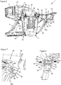
figure 3 illustre une vue en coupe de côté de l'aspirateur, le bol étant en début d'engagement sur le corps pour son assemblage avec ce dernier ; - les
figures 4 illustrent deux vues agrandies d'une partie de l'aspirateur, ces vues étant extraites respectivement deset 5figures 3 et 2 et mettant en évidence le système de guidage et de maintien dans deux positions ; - la
figure 6 illustre une vue en coupe de côté de l'aspirateur, le bol étant en fin d'engagement sur le corps, juste avant la mise en place automatique du système de verrouillage ; - la
figure 7 illustre le système de verrouillage juste avant sa mise en place automatique sur le corps ; - la
figure 8 illustre le système de verrouillage mis en place sur le corps ; - les
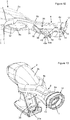
figures 9 à 11 illustrent le bol avec l'élément filtrant selon deux vues d'ensemble et selon une vue en coupe ; - la
figure 12 illustre partiellement le corps et le tube et met en évidence la présence de joints d'étanchéité ; - la
figure 13 illustre une vue d'ensemble du corps et du tube ; - les
figures 14 et 15 illustrent deux vues partielles de l'aspirateur mettant en évidence une variante du système de verrouillage, mis en place et juste avant sa mise en place.
- the
figure 1 illustrates an overview of the vacuum cleaner, the bowl being assembled with the body; - the
figure 2 illustrates a sectional side view of the vacuum cleaner, the bowl being assembled with the body; - the
figure 3 illustrates a sectional side view of the vacuum cleaner, the bowl being at the beginning of engagement on the body for its assembly with the latter; - the
Figures 4 and 5 illustrate two enlarged views of part of the vacuum cleaner, these views being extracted respectively fromfigures 3 and2 and highlighting the guiding and holding system in two positions; - the
figure 6 illustrates a side sectional view of the vacuum cleaner, the bowl being at the end of engagement on the body, just before the automatic installation of the locking system; - the
figure 7 illustrates the locking system just before its automatic placement on the body; - the
figure 8 illustrates the locking system put in place on the body; - the
Figures 9 to 11 illustrate the bowl with the filter element according to two overviews and in sectional view; - the
figure 12 partially illustrates the body and the tube and highlights the presence of seals; - the
figure 13 illustrates an overview of the body and the tube; - the
Figures 14 and 15 illustrate two partial views of the vacuum highlighting a variant of the locking system, put in place and just before its introduction.
Dans la suite de la description, l'aspirateur à main sans sac objet de l'invention sera dénommé aspirateur. En outre, les mêmes références seront utilisées pour désigner les mêmes caractéristiques selon les diverses variantes, sauf indication contraire.In the following description, the bagless hand vacuum object of the invention will be called vacuum cleaner. In addition, the same references will be used to designate the same characteristics according to the various variants, unless otherwise indicated.
Tel qu'illustré notamment sur les
Comme l'illustrent les
Tel qu'illustré en regard des
Tel qu'illustré par exemple en
Tel qu'illustré en regard des
Tel qu'illustré notamment en regard des
Afin de bloquer également les mouvements latéraux de la partie avant du bol 17 vis-à-vis du corps 2 et d'assurer le maintien du bol 17 avec la came 20 complètement engagée dans le chemin de came 21, la chambre d'aspiration 18 étant ainsi formée, l'aspirateur 1 comprend en complément un système de verrouillage 38 qui est mis en oeuvre entre la partie supérieure avant 17d du bol 17 et la partie avant 2b du corps 2, plus ou moins dans une zone de jonction 39 entre ledit corps 2 et le tube 6 formant un ensemble monobloc. De préférence, comme l'illustrent les
Une première réalisation du système de verrouillage 38 est décrite en regard des
Une seconde variante du système de verrouillage 38 est illustrée en
On pourra bien entendu envisager des variantes de l'aspirateur 1 sans sortir du cadre de l'invention. Des variantes du système de guidage et de maintien 19 peuvent notamment être envisagées en modifiant la forme de la came 20 et du chemin de came 21, ce qui modifiera sensiblement la trajectoire du bol 17 vis-à-vis du corps 2 lors de son engagement ou de son dégagement.We can of course consider variants of the
On peut également envisager des variantes du système de verrouillage 38 sans sortir du cadre de l'invention.It is also possible to envisage variants of the
Claims (15)
Applications Claiming Priority (1)
| Application Number | Priority Date | Filing Date | Title |
|---|---|---|---|
| FR1761153A FR3074026B1 (en) | 2017-11-24 | 2017-11-24 | HAND VACUUM WITHOUT BAG EQUIPPED WITH REMOVABLE BOWL |
Publications (2)
| Publication Number | Publication Date |
|---|---|
| EP3488749A1 true EP3488749A1 (en) | 2019-05-29 |
| EP3488749B1 EP3488749B1 (en) | 2020-09-30 |
Family
ID=61027952
Family Applications (1)
| Application Number | Title | Priority Date | Filing Date |
|---|---|---|---|
| EP18207902.0A Active EP3488749B1 (en) | 2017-11-24 | 2018-11-22 | Hand-held bagless vacuum cleaner provided with a removable bowl |
Country Status (4)
| Country | Link |
|---|---|
| EP (1) | EP3488749B1 (en) |
| CN (2) | CN109893027B (en) |
| ES (1) | ES2840227T3 (en) |
| FR (1) | FR3074026B1 (en) |
Cited By (1)
| Publication number | Priority date | Publication date | Assignee | Title |
|---|---|---|---|---|
| EP3865037A1 (en) * | 2020-02-13 | 2021-08-18 | Seb S.A. | Portable vacuum cleaner provided with a main casing comprising first and second separate casing portions |
Families Citing this family (7)
| Publication number | Priority date | Publication date | Assignee | Title |
|---|---|---|---|---|
| US11445878B2 (en) * | 2020-03-18 | 2022-09-20 | Omachron Intellectual Property Inc. | Surface cleaning apparatus with removable air treatment member assembly |
| US11730327B2 (en) | 2020-03-18 | 2023-08-22 | Omachron Intellectual Property Inc. | Surface cleaning apparatus with removable air treatment assembly |
| FR3074026B1 (en) * | 2017-11-24 | 2019-10-18 | Seb S.A. | HAND VACUUM WITHOUT BAG EQUIPPED WITH REMOVABLE BOWL |
| GB2586995B (en) * | 2019-09-11 | 2021-11-17 | Dyson Technology Ltd | An attachment for a vacuum cleaning appliance |
| AU2021237991A1 (en) | 2020-03-18 | 2022-11-17 | Omachron Intellectual Property Inc. | Surface cleaning apparatus with removable air treatment member assembly |
| FR3134304B1 (en) * | 2022-04-12 | 2024-04-12 | Seb Sa | Restitution of energy generated by an air flow within a suction device |
| FR3134305B1 (en) * | 2022-04-12 | 2024-04-12 | Seb Sa | Unclogging a vacuum cleaner filter by moving a mass |
Citations (2)
| Publication number | Priority date | Publication date | Assignee | Title |
|---|---|---|---|---|
| WO2014080179A1 (en) * | 2012-11-20 | 2014-05-30 | Dyson Technology Limited | Vacuum cleaner |
| WO2017147643A1 (en) * | 2016-02-29 | 2017-09-08 | Electrical Home-Aids Pty Ltd | A vacuum cleaner |
Family Cites Families (5)
| Publication number | Priority date | Publication date | Assignee | Title |
|---|---|---|---|---|
| CN106388707B (en) * | 2016-11-03 | 2019-04-09 | 江苏美的清洁电器股份有限公司 | Dirt cup component and hand-held cleaners with it |
| KR101414656B1 (en) * | 2012-08-31 | 2014-07-03 | 엘지전자 주식회사 | vacuum cleaner |
| EP2929824B1 (en) * | 2014-04-11 | 2018-06-06 | Black & Decker Inc. | A vacuum cleaning device |
| FR3030215B1 (en) * | 2014-12-19 | 2017-02-03 | Seb Sa | FLOW CLEANING APPARATUS |
| FR3074026B1 (en) * | 2017-11-24 | 2019-10-18 | Seb S.A. | HAND VACUUM WITHOUT BAG EQUIPPED WITH REMOVABLE BOWL |
-
2017
- 2017-11-24 FR FR1761153A patent/FR3074026B1/en not_active Expired - Fee Related
-
2018
- 2018-11-22 ES ES18207902T patent/ES2840227T3/en active Active
- 2018-11-22 EP EP18207902.0A patent/EP3488749B1/en active Active
- 2018-11-26 CN CN201811414659.6A patent/CN109893027B/en active Active
- 2018-11-26 CN CN201821951007.1U patent/CN209789735U/en not_active Withdrawn - After Issue
Patent Citations (2)
| Publication number | Priority date | Publication date | Assignee | Title |
|---|---|---|---|---|
| WO2014080179A1 (en) * | 2012-11-20 | 2014-05-30 | Dyson Technology Limited | Vacuum cleaner |
| WO2017147643A1 (en) * | 2016-02-29 | 2017-09-08 | Electrical Home-Aids Pty Ltd | A vacuum cleaner |
Cited By (3)
| Publication number | Priority date | Publication date | Assignee | Title |
|---|---|---|---|---|
| EP3865037A1 (en) * | 2020-02-13 | 2021-08-18 | Seb S.A. | Portable vacuum cleaner provided with a main casing comprising first and second separate casing portions |
| WO2021160671A1 (en) * | 2020-02-13 | 2021-08-19 | Seb S.A. | Portable vacuum cleaner having a main housing with first and second separate housing portions |
| FR3107173A1 (en) * | 2020-02-13 | 2021-08-20 | Seb S.A. | Portable vacuum cleaner equipped with a main housing comprising a first and a second separate housing parts |
Also Published As
| Publication number | Publication date |
|---|---|
| FR3074026A1 (en) | 2019-05-31 |
| ES2840227T3 (en) | 2021-07-06 |
| FR3074026B1 (en) | 2019-10-18 |
| CN109893027A (en) | 2019-06-18 |
| CN209789735U (en) | 2019-12-17 |
| EP3488749B1 (en) | 2020-09-30 |
| CN109893027B (en) | 2022-02-15 |
Similar Documents
| Publication | Publication Date | Title |
|---|---|---|
| EP3488749B1 (en) | Hand-held bagless vacuum cleaner provided with a removable bowl | |
| FR2852221A1 (en) | FILTER ASSEMBLY FOR A CYCLONE-TYPE DUST COLLECTION DEVICE OF A VACUUM CLEANER | |
| FR2852810A1 (en) | FILTER CLEANING DEVICE FOR A CYCLONE-TYPE VACUUM CLEANER | |
| FR2854047A1 (en) | Cyclone-type dust collecting apparatus for vacuum cleaner, has double impeller grill assembly to prevent air from flowing back via air outlet port, and fine dust collecting unit to collect dust which is not removed by assembly | |
| FR2786682A1 (en) | VACUUM EQUIPPED WITH A CYCLONIC DUST COLLECTOR | |
| FR2957510A1 (en) | Vacuum cleaner has component for separation of wastes, which has cyclone partition stage with primary separator by cyclone effect or inertia and another cyclone partition stage with multiple cyclone separators | |
| EP3488750B1 (en) | Hand-held bagless vacuum cleaner provided with a removable bowl | |
| FR2853220A1 (en) | Bagless vacuum cleaner has cover coupled to filter assembly, facilitating insertion and removal of filter assembly from filter mount | |
| WO2016181065A1 (en) | Pool cleaning apparatus with a filtration device that can be extracted via a lateral face | |
| FR2948004A1 (en) | Waste separating device for cyclonic vacuum cleaner, has cylindrical body extending till to base and connected with base, where waste separating device is separable from waste collection container | |
| WO2016097645A1 (en) | Cleaning appliance with airflow | |
| FR2849364A1 (en) | FIXING DEVICE FOR FIXING AND DETACHING A DUST CONTAINER FROM A CYCLONE-TYPE VACUUM AND VACUUM COMPRISING SUCH A DEVICE | |
| EP3476265B1 (en) | Robot vacuum cleaner incorporating a detachable hand vacuum cleaner | |
| EP3476266B1 (en) | Robot vacuum cleaner incorporating a detachable hand vacuum cleaner | |
| EP3954262B1 (en) | Portable vacuum cleaner provided with a removable filter | |
| WO1997012537A1 (en) | Vaccum cleaner and sealed bag for collecting waste material | |
| EP1956959B1 (en) | Vacuum cleaner dust receiver | |
| FR2795939A1 (en) | FLOOR CLEANER | |
| EP4039158B1 (en) | Suction assembly comprising a device for separating and collecting waste provided with locking members | |
| EP4039147B1 (en) | Canister-type suction assembly provided with a hatch for access to a rechargeable battery | |
| EP1535562B1 (en) | Waste separating device for vacuum cleaner | |
| EP4039157A1 (en) | Canister-type suction assembly provided with a hatch for access to a rechargeable battery | |
| WO2015090438A1 (en) | Autonomous cleaner | |
| FR2948005A1 (en) | Device for fastening inlet tube for cyclone vacuum cleaner, has connecting unit connecting inlet tube to cyclone separating unit, and mounting unit separated and spaced at distance from connecting unit |
Legal Events
| Date | Code | Title | Description |
|---|---|---|---|
| PUAI | Public reference made under article 153(3) epc to a published international application that has entered the european phase |
Free format text: ORIGINAL CODE: 0009012 |
|
| STAA | Information on the status of an ep patent application or granted ep patent |
Free format text: STATUS: THE APPLICATION HAS BEEN PUBLISHED |
|
| AK | Designated contracting states |
Kind code of ref document: A1 Designated state(s): AL AT BE BG CH CY CZ DE DK EE ES FI FR GB GR HR HU IE IS IT LI LT LU LV MC MK MT NL NO PL PT RO RS SE SI SK SM TR |
|
| AX | Request for extension of the european patent |
Extension state: BA ME |
|
| STAA | Information on the status of an ep patent application or granted ep patent |
Free format text: STATUS: REQUEST FOR EXAMINATION WAS MADE |
|
| 17P | Request for examination filed |
Effective date: 20191125 |
|
| RBV | Designated contracting states (corrected) |
Designated state(s): AL AT BE BG CH CY CZ DE DK EE ES FI FR GB GR HR HU IE IS IT LI LT LU LV MC MK MT NL NO PL PT RO RS SE SI SK SM TR |
|
| GRAP | Despatch of communication of intention to grant a patent |
Free format text: ORIGINAL CODE: EPIDOSNIGR1 |
|
| STAA | Information on the status of an ep patent application or granted ep patent |
Free format text: STATUS: GRANT OF PATENT IS INTENDED |
|
| INTG | Intention to grant announced |
Effective date: 20200508 |
|
| GRAS | Grant fee paid |
Free format text: ORIGINAL CODE: EPIDOSNIGR3 |
|
| GRAA | (expected) grant |
Free format text: ORIGINAL CODE: 0009210 |
|
| STAA | Information on the status of an ep patent application or granted ep patent |
Free format text: STATUS: THE PATENT HAS BEEN GRANTED |
|
| AK | Designated contracting states |
Kind code of ref document: B1 Designated state(s): AL AT BE BG CH CY CZ DE DK EE ES FI FR GB GR HR HU IE IS IT LI LT LU LV MC MK MT NL NO PL PT RO RS SE SI SK SM TR |
|
| REG | Reference to a national code |
Ref country code: CH Ref legal event code: EP Ref country code: GB Ref legal event code: FG4D Free format text: NOT ENGLISH |
|
| REG | Reference to a national code |
Ref country code: AT Ref legal event code: REF Ref document number: 1317897 Country of ref document: AT Kind code of ref document: T Effective date: 20201015 |
|
| REG | Reference to a national code |
Ref country code: DE Ref legal event code: R096 Ref document number: 602018008290 Country of ref document: DE |
|
| REG | Reference to a national code |
Ref country code: IE Ref legal event code: FG4D Free format text: LANGUAGE OF EP DOCUMENT: FRENCH |
|
| PG25 | Lapsed in a contracting state [announced via postgrant information from national office to epo] |
Ref country code: NO Free format text: LAPSE BECAUSE OF FAILURE TO SUBMIT A TRANSLATION OF THE DESCRIPTION OR TO PAY THE FEE WITHIN THE PRESCRIBED TIME-LIMIT Effective date: 20201230 Ref country code: BG Free format text: LAPSE BECAUSE OF FAILURE TO SUBMIT A TRANSLATION OF THE DESCRIPTION OR TO PAY THE FEE WITHIN THE PRESCRIBED TIME-LIMIT Effective date: 20201230 Ref country code: SE Free format text: LAPSE BECAUSE OF FAILURE TO SUBMIT A TRANSLATION OF THE DESCRIPTION OR TO PAY THE FEE WITHIN THE PRESCRIBED TIME-LIMIT Effective date: 20200930 Ref country code: HR Free format text: LAPSE BECAUSE OF FAILURE TO SUBMIT A TRANSLATION OF THE DESCRIPTION OR TO PAY THE FEE WITHIN THE PRESCRIBED TIME-LIMIT Effective date: 20200930 Ref country code: FI Free format text: LAPSE BECAUSE OF FAILURE TO SUBMIT A TRANSLATION OF THE DESCRIPTION OR TO PAY THE FEE WITHIN THE PRESCRIBED TIME-LIMIT Effective date: 20200930 Ref country code: GR Free format text: LAPSE BECAUSE OF FAILURE TO SUBMIT A TRANSLATION OF THE DESCRIPTION OR TO PAY THE FEE WITHIN THE PRESCRIBED TIME-LIMIT Effective date: 20201231 |
|
| REG | Reference to a national code |
Ref country code: AT Ref legal event code: MK05 Ref document number: 1317897 Country of ref document: AT Kind code of ref document: T Effective date: 20200930 |
|
| PG25 | Lapsed in a contracting state [announced via postgrant information from national office to epo] |
Ref country code: LV Free format text: LAPSE BECAUSE OF FAILURE TO SUBMIT A TRANSLATION OF THE DESCRIPTION OR TO PAY THE FEE WITHIN THE PRESCRIBED TIME-LIMIT Effective date: 20200930 Ref country code: RS Free format text: LAPSE BECAUSE OF FAILURE TO SUBMIT A TRANSLATION OF THE DESCRIPTION OR TO PAY THE FEE WITHIN THE PRESCRIBED TIME-LIMIT Effective date: 20200930 |
|
| REG | Reference to a national code |
Ref country code: NL Ref legal event code: MP Effective date: 20200930 |
|
| REG | Reference to a national code |
Ref country code: LT Ref legal event code: MG4D |
|
| PG25 | Lapsed in a contracting state [announced via postgrant information from national office to epo] |
Ref country code: SM Free format text: LAPSE BECAUSE OF FAILURE TO SUBMIT A TRANSLATION OF THE DESCRIPTION OR TO PAY THE FEE WITHIN THE PRESCRIBED TIME-LIMIT Effective date: 20200930 Ref country code: LT Free format text: LAPSE BECAUSE OF FAILURE TO SUBMIT A TRANSLATION OF THE DESCRIPTION OR TO PAY THE FEE WITHIN THE PRESCRIBED TIME-LIMIT Effective date: 20200930 Ref country code: EE Free format text: LAPSE BECAUSE OF FAILURE TO SUBMIT A TRANSLATION OF THE DESCRIPTION OR TO PAY THE FEE WITHIN THE PRESCRIBED TIME-LIMIT Effective date: 20200930 Ref country code: RO Free format text: LAPSE BECAUSE OF FAILURE TO SUBMIT A TRANSLATION OF THE DESCRIPTION OR TO PAY THE FEE WITHIN THE PRESCRIBED TIME-LIMIT Effective date: 20200930 Ref country code: PT Free format text: LAPSE BECAUSE OF FAILURE TO SUBMIT A TRANSLATION OF THE DESCRIPTION OR TO PAY THE FEE WITHIN THE PRESCRIBED TIME-LIMIT Effective date: 20210201 Ref country code: CZ Free format text: LAPSE BECAUSE OF FAILURE TO SUBMIT A TRANSLATION OF THE DESCRIPTION OR TO PAY THE FEE WITHIN THE PRESCRIBED TIME-LIMIT Effective date: 20200930 |
|
| PG25 | Lapsed in a contracting state [announced via postgrant information from national office to epo] |
Ref country code: PL Free format text: LAPSE BECAUSE OF FAILURE TO SUBMIT A TRANSLATION OF THE DESCRIPTION OR TO PAY THE FEE WITHIN THE PRESCRIBED TIME-LIMIT Effective date: 20200930 Ref country code: IS Free format text: LAPSE BECAUSE OF FAILURE TO SUBMIT A TRANSLATION OF THE DESCRIPTION OR TO PAY THE FEE WITHIN THE PRESCRIBED TIME-LIMIT Effective date: 20210130 Ref country code: AT Free format text: LAPSE BECAUSE OF FAILURE TO SUBMIT A TRANSLATION OF THE DESCRIPTION OR TO PAY THE FEE WITHIN THE PRESCRIBED TIME-LIMIT Effective date: 20200930 Ref country code: AL Free format text: LAPSE BECAUSE OF FAILURE TO SUBMIT A TRANSLATION OF THE DESCRIPTION OR TO PAY THE FEE WITHIN THE PRESCRIBED TIME-LIMIT Effective date: 20200930 |
|
| PG25 | Lapsed in a contracting state [announced via postgrant information from national office to epo] |
Ref country code: NL Free format text: LAPSE BECAUSE OF FAILURE TO SUBMIT A TRANSLATION OF THE DESCRIPTION OR TO PAY THE FEE WITHIN THE PRESCRIBED TIME-LIMIT Effective date: 20200930 Ref country code: SK Free format text: LAPSE BECAUSE OF FAILURE TO SUBMIT A TRANSLATION OF THE DESCRIPTION OR TO PAY THE FEE WITHIN THE PRESCRIBED TIME-LIMIT Effective date: 20200930 Ref country code: MC Free format text: LAPSE BECAUSE OF FAILURE TO SUBMIT A TRANSLATION OF THE DESCRIPTION OR TO PAY THE FEE WITHIN THE PRESCRIBED TIME-LIMIT Effective date: 20200930 |
|
| REG | Reference to a national code |
Ref country code: DE Ref legal event code: R097 Ref document number: 602018008290 Country of ref document: DE |
|
| REG | Reference to a national code |
Ref country code: ES Ref legal event code: FG2A Ref document number: 2840227 Country of ref document: ES Kind code of ref document: T3 Effective date: 20210706 |
|
| PG25 | Lapsed in a contracting state [announced via postgrant information from national office to epo] |
Ref country code: LU Free format text: LAPSE BECAUSE OF NON-PAYMENT OF DUE FEES Effective date: 20201122 |
|
| PLBE | No opposition filed within time limit |
Free format text: ORIGINAL CODE: 0009261 |
|
| STAA | Information on the status of an ep patent application or granted ep patent |
Free format text: STATUS: NO OPPOSITION FILED WITHIN TIME LIMIT |
|
| REG | Reference to a national code |
Ref country code: BE Ref legal event code: MM Effective date: 20201130 |
|
| PG25 | Lapsed in a contracting state [announced via postgrant information from national office to epo] |
Ref country code: DK Free format text: LAPSE BECAUSE OF FAILURE TO SUBMIT A TRANSLATION OF THE DESCRIPTION OR TO PAY THE FEE WITHIN THE PRESCRIBED TIME-LIMIT Effective date: 20200930 |
|
| 26N | No opposition filed |
Effective date: 20210701 |
|
| PG25 | Lapsed in a contracting state [announced via postgrant information from national office to epo] |
Ref country code: IE Free format text: LAPSE BECAUSE OF NON-PAYMENT OF DUE FEES Effective date: 20201122 |
|
| PG25 | Lapsed in a contracting state [announced via postgrant information from national office to epo] |
Ref country code: SI Free format text: LAPSE BECAUSE OF FAILURE TO SUBMIT A TRANSLATION OF THE DESCRIPTION OR TO PAY THE FEE WITHIN THE PRESCRIBED TIME-LIMIT Effective date: 20200930 |
|
| PGFP | Annual fee paid to national office [announced via postgrant information from national office to epo] |
Ref country code: ES Payment date: 20211203 Year of fee payment: 4 |
|
| PGFP | Annual fee paid to national office [announced via postgrant information from national office to epo] |
Ref country code: IT Payment date: 20211130 Year of fee payment: 4 |
|
| PG25 | Lapsed in a contracting state [announced via postgrant information from national office to epo] |
Ref country code: IS Free format text: LAPSE BECAUSE OF FAILURE TO SUBMIT A TRANSLATION OF THE DESCRIPTION OR TO PAY THE FEE WITHIN THE PRESCRIBED TIME-LIMIT Effective date: 20210130 Ref country code: TR Free format text: LAPSE BECAUSE OF FAILURE TO SUBMIT A TRANSLATION OF THE DESCRIPTION OR TO PAY THE FEE WITHIN THE PRESCRIBED TIME-LIMIT Effective date: 20200930 Ref country code: MT Free format text: LAPSE BECAUSE OF FAILURE TO SUBMIT A TRANSLATION OF THE DESCRIPTION OR TO PAY THE FEE WITHIN THE PRESCRIBED TIME-LIMIT Effective date: 20200930 Ref country code: CY Free format text: LAPSE BECAUSE OF FAILURE TO SUBMIT A TRANSLATION OF THE DESCRIPTION OR TO PAY THE FEE WITHIN THE PRESCRIBED TIME-LIMIT Effective date: 20200930 |
|
| PG25 | Lapsed in a contracting state [announced via postgrant information from national office to epo] |
Ref country code: MK Free format text: LAPSE BECAUSE OF FAILURE TO SUBMIT A TRANSLATION OF THE DESCRIPTION OR TO PAY THE FEE WITHIN THE PRESCRIBED TIME-LIMIT Effective date: 20200930 |
|
| REG | Reference to a national code |
Ref country code: CH Ref legal event code: PL |
|
| PG25 | Lapsed in a contracting state [announced via postgrant information from national office to epo] |
Ref country code: BE Free format text: LAPSE BECAUSE OF NON-PAYMENT OF DUE FEES Effective date: 20201130 |
|
| PG25 | Lapsed in a contracting state [announced via postgrant information from national office to epo] |
Ref country code: LI Free format text: LAPSE BECAUSE OF NON-PAYMENT OF DUE FEES Effective date: 20211130 Ref country code: CH Free format text: LAPSE BECAUSE OF NON-PAYMENT OF DUE FEES Effective date: 20211130 |
|
| GBPC | Gb: european patent ceased through non-payment of renewal fee |
Effective date: 20221122 |
|
| PG25 | Lapsed in a contracting state [announced via postgrant information from national office to epo] |
Ref country code: IT Free format text: LAPSE BECAUSE OF NON-PAYMENT OF DUE FEES Effective date: 20221122 Ref country code: GB Free format text: LAPSE BECAUSE OF NON-PAYMENT OF DUE FEES Effective date: 20221122 |
|
| REG | Reference to a national code |
Ref country code: ES Ref legal event code: FD2A Effective date: 20231228 |
|
| PG25 | Lapsed in a contracting state [announced via postgrant information from national office to epo] |
Ref country code: ES Free format text: LAPSE BECAUSE OF NON-PAYMENT OF DUE FEES Effective date: 20221123 |
|
| PG25 | Lapsed in a contracting state [announced via postgrant information from national office to epo] |
Ref country code: ES Free format text: LAPSE BECAUSE OF NON-PAYMENT OF DUE FEES Effective date: 20221123 |
|
| PGFP | Annual fee paid to national office [announced via postgrant information from national office to epo] |
Ref country code: FR Payment date: 20231124 Year of fee payment: 6 Ref country code: DE Payment date: 20231107 Year of fee payment: 6 |