EP4483701A1 - A chopper assembly for an agricultural harvester - Google Patents
A chopper assembly for an agricultural harvester Download PDFInfo
- Publication number
- EP4483701A1 EP4483701A1 EP23182296.6A EP23182296A EP4483701A1 EP 4483701 A1 EP4483701 A1 EP 4483701A1 EP 23182296 A EP23182296 A EP 23182296A EP 4483701 A1 EP4483701 A1 EP 4483701A1
- Authority
- EP
- European Patent Office
- Prior art keywords
- chopper
- sidewall
- guide surface
- drum
- knives
- Prior art date
- Legal status (The legal status is an assumption and is not a legal conclusion. Google has not performed a legal analysis and makes no representation as to the accuracy of the status listed.)
- Granted
Links
Images


Classifications
-
- A—HUMAN NECESSITIES
- A01—AGRICULTURE; FORESTRY; ANIMAL HUSBANDRY; HUNTING; TRAPPING; FISHING
- A01D—HARVESTING; MOWING
- A01D43/00—Mowers combined with apparatus performing additional operations while mowing
- A01D43/08—Mowers combined with apparatus performing additional operations while mowing with means for cutting up the mown crop, e.g. forage harvesters
-
- A—HUMAN NECESSITIES
- A01—AGRICULTURE; FORESTRY; ANIMAL HUSBANDRY; HUNTING; TRAPPING; FISHING
- A01F—PROCESSING OF HARVESTED PRODUCE; HAY OR STRAW PRESSES; DEVICES FOR STORING AGRICULTURAL OR HORTICULTURAL PRODUCE
- A01F29/00—Cutting apparatus specially adapted for cutting hay, straw or the like
- A01F29/02—Cutting apparatus specially adapted for cutting hay, straw or the like having rotating knives with their cutting edges in a plane perpendicular to their rotational axis
- A01F29/04—Cutting apparatus specially adapted for cutting hay, straw or the like having rotating knives with their cutting edges in a plane perpendicular to their rotational axis with feeding direction transverse to axis
-
- A—HUMAN NECESSITIES
- A01—AGRICULTURE; FORESTRY; ANIMAL HUSBANDRY; HUNTING; TRAPPING; FISHING
- A01F—PROCESSING OF HARVESTED PRODUCE; HAY OR STRAW PRESSES; DEVICES FOR STORING AGRICULTURAL OR HORTICULTURAL PRODUCE
- A01F29/00—Cutting apparatus specially adapted for cutting hay, straw or the like
- A01F29/02—Cutting apparatus specially adapted for cutting hay, straw or the like having rotating knives with their cutting edges in a plane perpendicular to their rotational axis
-
- A—HUMAN NECESSITIES
- A01—AGRICULTURE; FORESTRY; ANIMAL HUSBANDRY; HUNTING; TRAPPING; FISHING
- A01F—PROCESSING OF HARVESTED PRODUCE; HAY OR STRAW PRESSES; DEVICES FOR STORING AGRICULTURAL OR HORTICULTURAL PRODUCE
- A01F29/00—Cutting apparatus specially adapted for cutting hay, straw or the like
- A01F29/06—Cutting apparatus specially adapted for cutting hay, straw or the like having rotating knives with their cutting edges on a cylinder surface, e.g. of the helical-type
-
- A—HUMAN NECESSITIES
- A01—AGRICULTURE; FORESTRY; ANIMAL HUSBANDRY; HUNTING; TRAPPING; FISHING
- A01F—PROCESSING OF HARVESTED PRODUCE; HAY OR STRAW PRESSES; DEVICES FOR STORING AGRICULTURAL OR HORTICULTURAL PRODUCE
- A01F29/00—Cutting apparatus specially adapted for cutting hay, straw or the like
- A01F29/09—Details
- A01F29/10—Feeding devices
-
- A—HUMAN NECESSITIES
- A01—AGRICULTURE; FORESTRY; ANIMAL HUSBANDRY; HUNTING; TRAPPING; FISHING
- A01F—PROCESSING OF HARVESTED PRODUCE; HAY OR STRAW PRESSES; DEVICES FOR STORING AGRICULTURAL OR HORTICULTURAL PRODUCE
- A01F29/00—Cutting apparatus specially adapted for cutting hay, straw or the like
- A01F29/09—Details
- A01F29/12—Discharge means
Definitions
- the present invention is related to agricultural harvesters, in particular to a residue chopper assembly configured to be located at the rear of the harvester.
- a combine harvester In a combine harvester, crops like corn or wheat are cut and subsequently processed in order to separate grains from plant residue material.
- a combine harvester typically comprises a threshing section and a cleaning section, the latter including sieves for separating clean grains from smaller plant residue. The clean grains are collected in a trough at the bottom of the cleaning section, and thereafter transported to a grain tank higher up in the combine's structure.
- Residue material also referred to as material other than grain (MOG) needs to be removed from the harvester.
- the larger residue material can be chopped into smaller pieces in a chopper assembly, followed by a spreader which spreads the chopped residue particles in the form of a wide swath of residue material deposited on the field behind the advancing combine.
- the chopper assembly usually comprises a rotatable chopper drum comprising knives which move relative to stationary counterknives, to thereby chop the stalks into smaller particles.
- the drum is mounted transversally with respect to the fore-aft direction of the harvester, so that a stream of residue material is supplied to the chopping drum, with the width of the stream corresponding to the length of the drum.
- the knives are distributed at regular distances along the longitudinal direction of the drum, to thereby cut the stream of residue material into small particles.
- the chopper drum and counterknives are mounted between upright sidewalls which guide the stream of plant material towards the drum.
- a problem related to presently known chopper assemblies is that due to space constraints and assembly requirements, the knives closest to the sidewalls are necessarily placed at a certain distance from these sidewalls, so that stalks are able to pass through these lateral spaces without being cut.
- the invention is related to a chopper assembly and to a harvester as described in the appended claims.
- the chopper assembly comprises a rotatable chopper drum as known from the prior art, comprising a plurality of knives, mounted between two sidewalls and configured to cut larger plant material into smaller particles through the interaction of the knives and a set of counterknives.
- a guide surface is mounted on at least one of the sidewalls, preferably on both sidewalls, and in the path of a stream of crop material advancing towards the chopper assembly.
- the guide surface extends between an upstream edge lying essentially in the plane of the sidewall and a downstream edge removed from the sidewall.
- the guide surface is furthermore inclined relative to the sidewall, so as to guide plant material away from the sidewall and in the direction of the knives located closest to the sidewall. The guide surface thereby prevents plant material from passing between the knives and the sidewall without being cut.
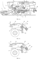
- a combine harvester 1 as presently known in the art includes an engine 2, a header 3 for cutting crops from the field, and for gathering the crops towards the inlet of a feeder 4.
- the feeder delivers the crops to one or two threshing rotors 5 which separate larger plant material from grains and smaller residue.
- the cleaning section 6 of the harvester includes a blower 7 and a plurality of sieves 8 for separating grains from the smaller residue. Insufficiently separated plant material is transported back to the threshing rotors via return augers 9. Fully separated grains are collected in a grain tank 10 through the combined action of a clean grain auger 11 and a grain elevator 12.
- the grains may be evacuated from the harvester through further augers 13 at the bottom of the grain tank and through a pivotable spout 14.
- Small plant residue also referred to as chaff, is blown towards the rear of the harvester by the blower 7.
- a stream of such larger plant material is thereby supplied in the direction of a chopper assembly 20, shown in more detail in Figures 1b and 1c .
- the chopper assembly comprises a chopper drum 21 that is rotatable in the indicated direction relative to a set of counterknives 22.
- the general direction of the stream of large plant residue is indicated by the arrows 16.
- Figures 1a -1c are intended only to indicate the general location of the chopper assembly in a combine harvester
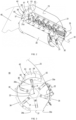
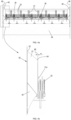
- Figures 2 to 4 show various images of an actual chopper assembly in accordance with an embodiment of the invention.
- the chopper drum 21 comprises a cylinder 30 with knives 31 pivotably attached thereto.
- the knives are arranged in linear rows mounted on the cylinder's surface at regular angular distances between consecutive rows, each row comprising knives mounted at regular linear distances in the longitudinal direction of the cylinder 30.
- the drum 21 is rotatable about its central rotation axis 32, the rotation being driven by a suitable drive mechanism known as such and therefore not described here in detail.
- a set of counterknives 22 is mounted so that the chopper knives 31 move in between the counterknives 22 as the drum rotates in the indicated direction, to thereby cut the plant residue into smaller pieces.
- the chopper drum 21 is mounted between a front concave 34 and a rear concave 35.
- Each of these concaves extends between an inlet edge (34a,34b) and an outlet edge (35a,35b). These edges respectively define an inlet opening 36 between inlet edges 34a and 35a and an outlet opening 37 between outlet edges 34b and 35b.
- the chopper assembly comprises guide surfaces 42 on the respective sidewalls 40.
- the main portion 51 (see Figures 2 and 3 ) of these surfaces 42 is oriented at an obtuse angle ⁇ relative to the respective sidewalls.
- the guide surfaces 42 extend between an upstream edge 53,55 lying essentially in the plane of the sidewalls 40 and a downstream edge 54,57 removed from the sidewalls in the longitudinal direction of the chopper drum 21.
- the guide surfaces 42 are thus inclined relative to the sidewalls 40 in such a manner as to guide plant material away from the sidewalls and in the direction of the outer knives 31a of the drum, i.e. the knives which are located closest to the sidewalls, thereby ensuring that essentially no plant stalks or other large plant material passes through the gap between these outer knives 31a and the sidewalls 40 without being cut.
- Figures 2 and 3 illustrate the shape of the guide surfaces 42 according to one embodiment of the invention. This particular shape is however just one example of a suitable shape, and other examples will be described later in this text.
- a common characteristic to all embodiments of the invention is that the guide surfaces force plant material at the sides of the incoming stream to be deflected towards the knives of the chopper drum 21.
- Figures 2 and 3 show one guide surface 42 mounted on one of the sidewalls 40.
- the other guide surface on the opposite sidewall is the mirror image of the illustrated guide surface 42.
- the invention is however not limited to embodiments wherein the guide surfaces are identical and mirrored. Although the latter represents an option that may be preferable in most harvester configurations, in some configurations it could be advantageous to provide guide surfaces on the two sidewalls which differ from each other in terms of their shapes and dimensions.
- the invention includes embodiments wherein a guide surface is only present on one side of the chopper drum, on one of the sidewalls 40, while no guide surface is mounted on the opposite sidewall. This may be appropriate in cases were the gap between the knives and one of the sidewalls is smaller on one side than on the opposite side for example.
- the guide surface 42 in the illustrated embodiment is part of a welded piece that is bolted to the side wall 40.
- the guide surface is thereby removably attached to the sidewall.
- the guide surface may be permanently attached or uniform with the sidewall.
- the guide surface is mounted in the path of the incoming crop stream.
- the guide surface 42 is located across the inlet opening 36, i.e. along one lateral side of said inlet opening. Other locations of the guide surface are possible, as will be illustrated later.
- the conical portion 51 extends between a first curved edge 53 and a second curved edge 54.
- the first curved edge 53 is essentially in the plane of the sidewall 40.
- the second curved edge 54 is located in an end plane 49 that is perpendicular to the drum's rotation axis 32 and adjacent to the knives 31a located closest to the sidewall 40, with a small gap w remaining between said end plane 49 and the knives 31a.
- the gap w is situated on the far side of the knives 31a, as seen from the middle of the drum cylinder 30.
- the width of the guide surface 42 (as measured in the direction of the drum's rotation axis 32) almost fills the distance between the knives 31a and the sidewalls 40 but does not overlap with said knives 31a (i.e. the knives closest to the sidewalls). A small overlap with said closest knives 31a may nevertheless be allowed, although it cannot be so big as to obstruct the cutting function of the knives 31a.
- the second curved edge 54 does not overlap the knives 31 when the knives are oriented radially with respect to the cylinder, i.e. when the drum is rotating at a sufficient speed so that the knives are forced into this radial position along radius R by the centrifugal force.
- this latter feature guide surface does not overlap the knives in the side view
- the first triangular side portion 50 extends between a straight edge 55 essentially in the plane of the sidewall 40, a lateral edge 56 of the conical portion 51, and a curved lower edge 57.
- This inclined triangular portion 50 optimizes the guidance of crops at one side of the inlet gap.
- the invention is however not limited to guide surfaces comprising this triangular side portion 50.
- the triangular plate element 52 closes off the conical portion 51 on the side opposite the side at which the first triangular portion 50 is located. As stated, the surface of the plate element 52 is not to be regarded as part of the guide surface 42 as such.
- FIG. 5 Another element that is optional is illustrated in the detail image in Figure 5 . It is seen that a cylindrical bottom plate element 60 blocks the entry of plant material into the space between the sidewall 40 and the downstream edge 54,57. This cylindrical plate element 60 thereby prevents crops from accumulating in this space.
- the invention is not limited to the specific shape of the guide surfaces shown in Figures 2-4 .
- the surfaces could have more rudimental shapes, as long as they are suitable for guiding the crops away from the sidewalls and towards the knives 31a closest to the sidewalls.
- the guide surfaces could be flat surfaces oriented at a suitable obtuse angle in the direction of the knives.
- the shape may be more intricate than illustrated, for example comprising several portions oriented at one or more different obtuse angles relative to the sidewall.
- the guide surfaces are not placed directly in the inlet opening 36 but more upstream in the path of the plant material.
- the guide surface 65 is a straight inclined surface placed at an angle ⁇ to the inlet opening 36 and inclined at an obtuse angle ⁇ with respect to the sidewall 40.
- the guide surface 65 in this embodiment is a plate element that is uniform with a strip 69 bolted to the sidewall 40.
- the guide surface 65 extends between an upstream edge 66 and a downstream edge 67.
- a guide plate 68 is attached to the downstream edge 67.
- the guide plate 68 is oriented perpendicularly to the drum's rotation axis 32 and located adjacent and in close proximity to the outer knives 31a.
Landscapes
- Life Sciences & Earth Sciences (AREA)
- Environmental Sciences (AREA)
- Outside Dividers And Delivering Mechanisms For Harvesters (AREA)
Abstract
Description
- The present invention is related to agricultural harvesters, in particular to a residue chopper assembly configured to be located at the rear of the harvester.
- In a combine harvester, crops like corn or wheat are cut and subsequently processed in order to separate grains from plant residue material. A combine harvester typically comprises a threshing section and a cleaning section, the latter including sieves for separating clean grains from smaller plant residue. The clean grains are collected in a trough at the bottom of the cleaning section, and thereafter transported to a grain tank higher up in the combine's structure.
- Residue material, also referred to as material other than grain (MOG) needs to be removed from the harvester. This includes larger plant material such as stalks collected at the end of the threshing section, and smaller material blown towards the rear of the harvester by the cleaning fan. Before being evacuated from the harvester, the larger residue material can be chopped into smaller pieces in a chopper assembly, followed by a spreader which spreads the chopped residue particles in the form of a wide swath of residue material deposited on the field behind the advancing combine.
- The chopper assembly usually comprises a rotatable chopper drum comprising knives which move relative to stationary counterknives, to thereby chop the stalks into smaller particles. The drum is mounted transversally with respect to the fore-aft direction of the harvester, so that a stream of residue material is supplied to the chopping drum, with the width of the stream corresponding to the length of the drum. The knives are distributed at regular distances along the longitudinal direction of the drum, to thereby cut the stream of residue material into small particles. The chopper drum and counterknives are mounted between upright sidewalls which guide the stream of plant material towards the drum.
- A problem related to presently known chopper assemblies is that due to space constraints and assembly requirements, the knives closest to the sidewalls are necessarily placed at a certain distance from these sidewalls, so that stalks are able to pass through these lateral spaces without being cut.
- The invention is related to a chopper assembly and to a harvester as described in the appended claims. The chopper assembly comprises a rotatable chopper drum as known from the prior art, comprising a plurality of knives, mounted between two sidewalls and configured to cut larger plant material into smaller particles through the interaction of the knives and a set of counterknives. According to the invention, a guide surface is mounted on at least one of the sidewalls, preferably on both sidewalls, and in the path of a stream of crop material advancing towards the chopper assembly. The guide surface extends between an upstream edge lying essentially in the plane of the sidewall and a downstream edge removed from the sidewall. The guide surface is furthermore inclined relative to the sidewall, so as to guide plant material away from the sidewall and in the direction of the knives located closest to the sidewall. The guide surface thereby prevents plant material from passing between the knives and the sidewall without being cut.
-
-
Figure 1a is a side view illustrating the main components of a combine harvester as known in the prior art, including the location of the chopper assembly and the residue spreader.Figures 1b and 1c illustrate the functioning of the chopper assembly and the spreader. -
Figure 2 is a 3D section view illustrating the position of one of the guide surfaces in a chopper assembly according to an embodiment of the invention. -
Figure 3 is a 2D section view of the chopper assembly ofFigure 2 , as seen in the direction of the chopper drum's rotation axis. -
Figure 4a is a frontal view of the chopper drum including the two guide surfaces in a chopper assembly according to an embodiment of the invention.Figure 4b is an enlarged detail, showing the position of one of the guide surfaces. -
Figure 5 is a detailed view of the guide surface according to an embodiment of the invention. -
Figures 6a and 6b illustrate another embodiment of the invention wherein the guide surfaces are located upstream of the inlet opening of the chopper assembly. - Preferred embodiments will now be described with reference to the drawings. The detailed description is not limiting the scope of the invention, which is defined only by the appended claims.
- With reference to
Figure 1a , a combine harvester 1 as presently known in the art includes anengine 2, aheader 3 for cutting crops from the field, and for gathering the crops towards the inlet of a feeder 4. The feeder delivers the crops to one or twothreshing rotors 5 which separate larger plant material from grains and smaller residue. Thecleaning section 6 of the harvester includes ablower 7 and a plurality of sieves 8 for separating grains from the smaller residue. Insufficiently separated plant material is transported back to the threshing rotors viareturn augers 9. Fully separated grains are collected in agrain tank 10 through the combined action of aclean grain auger 11 and agrain elevator 12. From thetank 10, the grains may be evacuated from the harvester throughfurther augers 13 at the bottom of the grain tank and through apivotable spout 14. Small plant residue, also referred to as chaff, is blown towards the rear of the harvester by theblower 7. - Larger plant residue such as plant stalks and leaves, arrives at the end of the
threshing rotors 5 and is subsequently moved to the rear of the harvester by abeater drum 15. A stream of such larger plant material is thereby supplied in the direction of achopper assembly 20, shown in more detail inFigures 1b and 1c . The chopper assembly comprises achopper drum 21 that is rotatable in the indicated direction relative to a set ofcounterknives 22. The general direction of the stream of large plant residue is indicated by thearrows 16. Apivotable cover 23 is arranged to direct the stream either towards thechopper drum 20 to be cut into smaller particles (as shown inFigure 1b ) or directly towards anejection chute 24 without being cut (as shown inFigure 1c ). Downstream of thechopper drum 21,spreader wheels 25 are mounted. The spreader wheels receive a stream of chopped particles from the chopper assembly (when thecover 23 is pivoted downward) and aseparate stream 17 of chaff from thecleaning section 6. Thespreader wheels 25 spread out the chaff and chopped particles across a wide swath at the rear of the combine. - Whereas
Figures 1a -1c are intended only to indicate the general location of the chopper assembly in a combine harvester,Figures 2 to 4 show various images of an actual chopper assembly in accordance with an embodiment of the invention. - A number of components of the represented embodiment which are known as such will be described first. The
chopper drum 21 comprises acylinder 30 withknives 31 pivotably attached thereto. The knives are arranged in linear rows mounted on the cylinder's surface at regular angular distances between consecutive rows, each row comprising knives mounted at regular linear distances in the longitudinal direction of thecylinder 30. Thedrum 21 is rotatable about itscentral rotation axis 32, the rotation being driven by a suitable drive mechanism known as such and therefore not described here in detail. A set ofcounterknives 22 is mounted so that thechopper knives 31 move in between thecounterknives 22 as the drum rotates in the indicated direction, to thereby cut the plant residue into smaller pieces. - In the front-aft direction of the combine, the
chopper drum 21 is mounted between a front concave 34 and a rear concave 35. Each of these concaves extends between an inlet edge (34a,34b) and an outlet edge (35a,35b). These edges respectively define an inlet opening 36 betweeninlet edges outlet edges pivotable cover 23 in the downward position as shown inFigures 2 and 3 , the path of the plant material coming from the threshing rotors passes through the inlet opening 36, and a stream of chopped particles is ejected through the outlet opening 37. In the transversal direction, and as best visible inFigure 4a , thedrum 21 is rotatably mounted betweenupright sidewalls 40. - In accordance with the invention, the chopper assembly comprises
guide surfaces 42 on therespective sidewalls 40. The main portion 51 (seeFigures 2 and 3 ) of thesesurfaces 42 is oriented at an obtuse angle β relative to the respective sidewalls. Theguide surfaces 42 extend between anupstream edge sidewalls 40 and adownstream edge chopper drum 21. Theguide surfaces 42 are thus inclined relative to thesidewalls 40 in such a manner as to guide plant material away from the sidewalls and in the direction of theouter knives 31a of the drum, i.e. the knives which are located closest to the sidewalls, thereby ensuring that essentially no plant stalks or other large plant material passes through the gap between theseouter knives 31a and thesidewalls 40 without being cut. -
Figures 2 and 3 illustrate the shape of theguide surfaces 42 according to one embodiment of the invention. This particular shape is however just one example of a suitable shape, and other examples will be described later in this text. A common characteristic to all embodiments of the invention is that the guide surfaces force plant material at the sides of the incoming stream to be deflected towards the knives of thechopper drum 21. -
Figures 2 and 3 show oneguide surface 42 mounted on one of thesidewalls 40. The other guide surface on the opposite sidewall is the mirror image of the illustratedguide surface 42. The invention is however not limited to embodiments wherein the guide surfaces are identical and mirrored. Although the latter represents an option that may be preferable in most harvester configurations, in some configurations it could be advantageous to provide guide surfaces on the two sidewalls which differ from each other in terms of their shapes and dimensions. Also, the invention includes embodiments wherein a guide surface is only present on one side of the chopper drum, on one of thesidewalls 40, while no guide surface is mounted on the opposite sidewall. This may be appropriate in cases were the gap between the knives and one of the sidewalls is smaller on one side than on the opposite side for example. - As seen in the drawings, the
guide surface 42 in the illustrated embodiment is part of a welded piece that is bolted to theside wall 40. The guide surface is thereby removably attached to the sidewall. According to other embodiments however, the guide surface may be permanently attached or uniform with the sidewall. - In any embodiment of the invention, the guide surface is mounted in the path of the incoming crop stream. In the embodiment shown in
Figures 2 and 3 , theguide surface 42 is located across theinlet opening 36, i.e. along one lateral side of said inlet opening. Other locations of the guide surface are possible, as will be illustrated later. - In the embodiment shown, the welded piece comprises plate elements whose outer surfaces define the
guide surface 42, which comprises atriangular side portion 50 and a conicalmain portion 51. Atriangular plate element 52 is located on the opposite side of the firsttriangular portion 50. The outer surface of thislatter plate element 52 is more or less perpendicular to thesidewall 40 and is therefore not a part of the guide surface as such. - The
conical portion 51 extends between a firstcurved edge 53 and a secondcurved edge 54. The firstcurved edge 53 is essentially in the plane of thesidewall 40. As best seen inFigure 4b , the secondcurved edge 54 is located in anend plane 49 that is perpendicular to the drum'srotation axis 32 and adjacent to theknives 31a located closest to thesidewall 40, with a small gap w remaining between saidend plane 49 and theknives 31a. According to the embodiment shown in the drawing, the gap w is situated on the far side of theknives 31a, as seen from the middle of thedrum cylinder 30. In other words, the width of the guide surface 42 (as measured in the direction of the drum's rotation axis 32) almost fills the distance between theknives 31a and thesidewalls 40 but does not overlap with saidknives 31a (i.e. the knives closest to the sidewalls). A small overlap with saidclosest knives 31a may nevertheless be allowed, although it cannot be so big as to obstruct the cutting function of theknives 31a. - As seen in the side view regarded along the drum's
rotation axis 32 inFigure 3 , the secondcurved edge 54 does not overlap theknives 31 when the knives are oriented radially with respect to the cylinder, i.e. when the drum is rotating at a sufficient speed so that the knives are forced into this radial position along radius R by the centrifugal force. Although this latter feature (guide surface does not overlap the knives in the side view) is not a limiting feature of the invention, it is nevertheless preferred in order to avoid plant material becoming stuck between theouter knives 31a and theguide surface 42. - The first
triangular side portion 50 extends between astraight edge 55 essentially in the plane of thesidewall 40, alateral edge 56 of theconical portion 51, and a curvedlower edge 57. This inclinedtriangular portion 50 optimizes the guidance of crops at one side of the inlet gap. The invention is however not limited to guide surfaces comprising thistriangular side portion 50. - The
triangular plate element 52 closes off theconical portion 51 on the side opposite the side at which the firsttriangular portion 50 is located. As stated, the surface of theplate element 52 is not to be regarded as part of theguide surface 42 as such. - The
guide surface 42 in the case of the illustrated embodiment is therefore formed by the combinedportions edges edges - Another element that is optional is illustrated in the detail image in
Figure 5 . It is seen that a cylindricalbottom plate element 60 blocks the entry of plant material into the space between thesidewall 40 and thedownstream edge cylindrical plate element 60 thereby prevents crops from accumulating in this space. - As stated above, the invention is not limited to the specific shape of the guide surfaces shown in
Figures 2-4 . The surfaces could have more rudimental shapes, as long as they are suitable for guiding the crops away from the sidewalls and towards theknives 31a closest to the sidewalls. In stead of having a conical shape for example, the guide surfaces could be flat surfaces oriented at a suitable obtuse angle in the direction of the knives. On the other hand, the shape may be more intricate than illustrated, for example comprising several portions oriented at one or more different obtuse angles relative to the sidewall. - According to another embodiment, the guide surfaces are not placed directly in the inlet opening 36 but more upstream in the path of the plant material. Such an embodiment is illustrated in
Figure 6 . Theguide surface 65 is a straight inclined surface placed at an angle α to theinlet opening 36 and inclined at an obtuse angle β with respect to thesidewall 40. Theguide surface 65 in this embodiment is a plate element that is uniform with astrip 69 bolted to thesidewall 40. Theguide surface 65 extends between anupstream edge 66 and adownstream edge 67. In addition, aguide plate 68 is attached to thedownstream edge 67. Theguide plate 68 is oriented perpendicularly to the drum'srotation axis 32 and located adjacent and in close proximity to theouter knives 31a. After being deflected from the sidewall by theguide surface 65, plant material is guided along theguide plate 68 towards the knives. Like the embodiment ofFigures 2 to 4 , the effect is also that plant material is inhibited from passing between the sidewalls and the knives without being cut. Instead of thestraight guide surface 65, more intricate shapes of the guide surfaces can be applied in this embodiment, i.e. placed upstream of the inlet opening and combined with aguide plate 68. - It is understood therefore that various embodiments not described here explicitly are within the scope of the appended claims.
Claims (15)
- A chopper assembly for an agricultural harvester, the assembly comprising :- a chopper drum (20) comprising a plurality of chopper knives (31) arranged along the longitudinal direction of the drum, wherein the drum is rotatable about a longitudinal rotation axis (32),- a set of counterknives (22),- a pair of sidewalls (40) oriented transversely with respect to the rotation axis of the chopper drum, with the drum rotatably mounted between said sidewalls,- an inlet opening (36) and an outlet opening (37), each comprising a first and second lateral side arranged along the respective sidewalls (40),wherein the chopper assembly is configured to :- receive through said inlet opening (36) a stream of plant material advancing between the sidewalls (40),- cut the plant material into particles,- eject the particles through the outlet opening (37),characterized in that the assembly further comprises at least one guide surface (42,65) mounted on at least one of the sidewalls (40), wherein said guide surface:- extends between an upstream edge (53,55;66) lying essentially in the plane of the sidewall (40) and a downstream edge (54,57;67) removed from the sidewall (40),- is inclined relative to the sidewall (40) so as to guide said plant material away from the sidewall and in the direction of the chopper knives (31a) located closest to the sidewall (40).
- The chopper assembly according to claim 1, wherein at least a portion of the downstream edge (54,57;68) of the guide surface (42,65) is lying in an end plane (49) oriented essentially perpendicularly to the drum's rotation axis (32).
- The chopper assembly according to claim 2, wherein said end plane (49) is located in close proximity to said knives (31a) located closest to the sidewall (40), whilst lying on the far side of said knives (31a) as seen from the middle of the chopper drum (21).
- The chopper assembly according to claim 2 or 3, wherein the guide surface (42) comprises or consists of a conical surface portion (51) extending between curved portions (53,54) of said upstream and downstream edges.
- The chopper assembly according to claim 4, wherein the curved portion (54) of the downstream edge does not overlap the knives (31) as seen in a side view along the chopper drum's rotation axis (32), when the chopper drum (21) is rotating.
- The chopper assembly according to any one of the preceding claims, wherein the guide surface (42) comprises one or more portions oriented at one or more different obtuse angles (β) to the sidewall (40).
- The chopper assembly according to claim 6, wherein the guide surface (42) comprises a conical portion (51) and a triangular portion (50) to one lateral side of the conical portion.
- The chopper assembly according to any one of the preceding claims, wherein the guide surface (42) is located across the inlet opening (36), at a lateral side thereof.
- The chopper assembly according to any one of claims 1 to 7, wherein the guide surface (65) is located upstream of a lateral side of the inlet opening (36).
- The chopper assembly according to claim 9, further comprising a guide plate (68) attached to the downstream edge (67) of the guide surface (65), and oriented essentially perpendicularly to the drum's rotation axis (32) and configured to guide plant material from the downstream edge (67) of the guide surface in the direction of the knives (31a) closest to the sidewall (40).
- The chopper assembly according to any one of the preceding claims, wherein the guide surface (42,65) is part of a separate piece that is removably attached to the sidewall (40).
- The chopper assembly according to any one of the preceding claims, wherein the guide surface (42,65) is realized by at least one plate element oriented at an obtuse angle from the sidewall (40), so that an open space is created between said plate element and the sidewall (40), and wherein an additional plate element (60) is mounted between the downstream edge (54,57) and the sidewall (40), so as to block entry of plant material into said open space in a direction perpendicular to the upstream edge.
- The chopper assembly according to any one of the preceding claims, comprising a first and second concave (34,35) with the chopper drum (20) mounted between said concaves, wherein both concaves comprise an inlet edge (34a,35a) and an outlet edge (34b,35b), so that said inlet opening (36) is formed between the inlet edges and said outlet opening (37) is formed between the outlet edges.
- The chopper assembly according to any one of the preceding claims, wherein guide surfaces (42) are mounted on both sidewalls (40), said guide surfaces being identical in shape and dimensions but mirrored relative to each other with respect to a plane perpendicular to the drum's rotation axis (32).
- An agricultural harvester comprising a chopper assembly in accordance with any one of the preceding claims.
Priority Applications (2)
| Application Number | Priority Date | Filing Date | Title |
|---|---|---|---|
| EP23182296.6A EP4483701B1 (en) | 2023-06-29 | 2023-06-29 | A chopper assembly for an agricultural harvester |
| US18/752,884 US20250000030A1 (en) | 2023-06-29 | 2024-06-25 | Chopper assembly for an agricultural harvester |
Applications Claiming Priority (1)
| Application Number | Priority Date | Filing Date | Title |
|---|---|---|---|
| EP23182296.6A EP4483701B1 (en) | 2023-06-29 | 2023-06-29 | A chopper assembly for an agricultural harvester |
Publications (2)
| Publication Number | Publication Date |
|---|---|
| EP4483701A1 true EP4483701A1 (en) | 2025-01-01 |
| EP4483701B1 EP4483701B1 (en) | 2026-02-04 |
Family
ID=87060434
Family Applications (1)
| Application Number | Title | Priority Date | Filing Date |
|---|---|---|---|
| EP23182296.6A Active EP4483701B1 (en) | 2023-06-29 | 2023-06-29 | A chopper assembly for an agricultural harvester |
Country Status (2)
| Country | Link |
|---|---|
| US (1) | US20250000030A1 (en) |
| EP (1) | EP4483701B1 (en) |
Citations (6)
| Publication number | Priority date | Publication date | Assignee | Title |
|---|---|---|---|---|
| US2857946A (en) * | 1956-02-09 | 1958-10-28 | Benjamin L Nikkel | Forage cutter and blower |
| EP3092891A1 (en) * | 2015-04-30 | 2016-11-16 | CNH Industrial Belgium nv | Chopper for an agricultural harvester |
| CN107980337A (en) * | 2017-12-20 | 2018-05-04 | 杨雪锋 | A kind of maize straw gathers in breaker automatically |
| US20180343805A1 (en) * | 2017-05-30 | 2018-12-06 | Deere & Company | Agricultural combine with reversing chopper rotor |
| US10251342B2 (en) * | 2016-11-01 | 2019-04-09 | Indústrias Reunidas Colombo Ltda | Chopping module having box-shaped body, rollers, shearbar, and rotating blade assembly |
| CN115316138A (en) * | 2022-08-18 | 2022-11-11 | 重庆交通大学 | Agricultural straw equipment is handled to movable pyrolysis technology |
Family Cites Families (14)
| Publication number | Priority date | Publication date | Assignee | Title |
|---|---|---|---|---|
| GB462128A (en) * | 1935-09-02 | 1937-03-02 | Blairs Ltd | Improved apparatus for cutting and shredding sugar cane |
| US3186460A (en) * | 1961-07-20 | 1965-06-01 | Frederick Joseph | Straw chopping apparatus |
| US3224688A (en) * | 1962-01-22 | 1965-12-21 | Honolulu Iron Works Company | Shredder |
| US4208858A (en) * | 1979-02-12 | 1980-06-24 | Sperry Rand Corporation | Isolated pneumatic cleaning system |
| US4506840A (en) * | 1983-08-31 | 1985-03-26 | Sperry Corporation | Baffle means for forage harvesters |
| SE468784B (en) * | 1991-07-22 | 1993-03-22 | Rekordverken Ab | BATH HACK, PROVIDED WITH LOCAL ADJUSTABLE ANIMALS WHICH MAY BE COVERED WITH A COVER |
| DE19603370C2 (en) * | 1996-01-31 | 1998-12-17 | Deere & Co | Harvester |
| CA3159989C (en) * | 2015-07-14 | 2024-10-22 | Tritana Intellectual Property Ltd. | Combine harvester with straw spreading and weed seed destruction |
| US10375885B2 (en) * | 2015-09-17 | 2019-08-13 | Deere & Company | System for chopping and spreading residue |
| EP3172959B1 (en) * | 2015-11-27 | 2018-09-12 | CNH Industrial Belgium nv | Chopper and spreader for an agricultural harvester |
| US10244685B2 (en) * | 2016-08-16 | 2019-04-02 | Tribine Industries Llc | Straw choppers for an articulated harvesting combine |
| US10390491B2 (en) * | 2017-06-13 | 2019-08-27 | Deere & Company | Cleaning shoe venting through chopper rotor assembly |
| US10952373B2 (en) * | 2017-08-29 | 2021-03-23 | Deere & Company | Straw deflector for an agricultural combine |
| JP7033521B2 (en) * | 2018-09-26 | 2022-03-10 | ヤンマーパワーテクノロジー株式会社 | combine |
-
2023
- 2023-06-29 EP EP23182296.6A patent/EP4483701B1/en active Active
-
2024
- 2024-06-25 US US18/752,884 patent/US20250000030A1/en active Pending
Patent Citations (6)
| Publication number | Priority date | Publication date | Assignee | Title |
|---|---|---|---|---|
| US2857946A (en) * | 1956-02-09 | 1958-10-28 | Benjamin L Nikkel | Forage cutter and blower |
| EP3092891A1 (en) * | 2015-04-30 | 2016-11-16 | CNH Industrial Belgium nv | Chopper for an agricultural harvester |
| US10251342B2 (en) * | 2016-11-01 | 2019-04-09 | Indústrias Reunidas Colombo Ltda | Chopping module having box-shaped body, rollers, shearbar, and rotating blade assembly |
| US20180343805A1 (en) * | 2017-05-30 | 2018-12-06 | Deere & Company | Agricultural combine with reversing chopper rotor |
| CN107980337A (en) * | 2017-12-20 | 2018-05-04 | 杨雪锋 | A kind of maize straw gathers in breaker automatically |
| CN115316138A (en) * | 2022-08-18 | 2022-11-11 | 重庆交通大学 | Agricultural straw equipment is handled to movable pyrolysis technology |
Also Published As
| Publication number | Publication date |
|---|---|
| US20250000030A1 (en) | 2025-01-02 |
| EP4483701B1 (en) | 2026-02-04 |
Similar Documents
| Publication | Publication Date | Title |
|---|---|---|
| US7063613B2 (en) | Combine with straw chopper | |
| EP2138024B1 (en) | Active spreader for an agricultural combine | |
| US7104883B2 (en) | Straw chopper blade | |
| CA2693933C (en) | Harvester comprising an additional drum conveyor for conveying straw and a single flap for changing between swath deposit and shredding operation | |
| US10130033B2 (en) | Combine harvester with improved chopper and spreader arrangement | |
| US8864561B2 (en) | Harvested crop residue chopper and distribution arrangement for a combine with an impeller blower whose shape conforms to the contour of the straw chopper | |
| EP3409095B1 (en) | Agricultural combine with reversing chopper rotor | |
| EP3449717B1 (en) | Straw deflector for an agricultural combine | |
| US8128466B2 (en) | Harvested material residue chopping and distributing arrangement for a combine | |
| EP3092891B1 (en) | Chopper for an agricultural harvester | |
| EP3087825B1 (en) | Agricultural harvester auger assembly | |
| EP3087821B1 (en) | Agricultural header with multiple finger infeed assembly | |
| WO2016077686A1 (en) | Agricultural harvester with a rotated elevator | |
| EP4483701B1 (en) | A chopper assembly for an agricultural harvester | |
| EP4385306B1 (en) | Crop residue spreader arrangement | |
| US20180177126A1 (en) | Straw spreader and chaff spreader for a combine harvester | |
| US20220053702A1 (en) | Combine feederhouse with crop flow splitter | |
| CN107846844B (en) | Auger assembly for agricultural harvester | |
| US20250048973A1 (en) | Straw Chopper for a Combine Harvester | |
| US20240215482A1 (en) | Crop Residue Spreader Arrangement | |
| US20260060180A1 (en) | Threshing system of a combine harvester |
Legal Events
| Date | Code | Title | Description |
|---|---|---|---|
| PUAI | Public reference made under article 153(3) epc to a published international application that has entered the european phase |
Free format text: ORIGINAL CODE: 0009012 |
|
| STAA | Information on the status of an ep patent application or granted ep patent |
Free format text: STATUS: THE APPLICATION HAS BEEN PUBLISHED |
|
| AK | Designated contracting states |
Kind code of ref document: A1 Designated state(s): AL AT BE BG CH CY CZ DE DK EE ES FI FR GB GR HR HU IE IS IT LI LT LU LV MC ME MK MT NL NO PL PT RO RS SE SI SK SM TR |
|
| STAA | Information on the status of an ep patent application or granted ep patent |
Free format text: STATUS: REQUEST FOR EXAMINATION WAS MADE |
|
| 17P | Request for examination filed |
Effective date: 20250701 |
|
| GRAP | Despatch of communication of intention to grant a patent |
Free format text: ORIGINAL CODE: EPIDOSNIGR1 |
|
| STAA | Information on the status of an ep patent application or granted ep patent |
Free format text: STATUS: GRANT OF PATENT IS INTENDED |
|
| RIC1 | Information provided on ipc code assigned before grant |
Ipc: A01D 43/08 20060101AFI20250804BHEP Ipc: A01F 29/06 20060101ALI20250804BHEP Ipc: A01F 29/10 20060101ALI20250804BHEP |
|
| INTG | Intention to grant announced |
Effective date: 20250826 |
|
| GRAS | Grant fee paid |
Free format text: ORIGINAL CODE: EPIDOSNIGR3 |
|
| GRAA | (expected) grant |
Free format text: ORIGINAL CODE: 0009210 |
|
| STAA | Information on the status of an ep patent application or granted ep patent |
Free format text: STATUS: THE PATENT HAS BEEN GRANTED |
|
| AK | Designated contracting states |
Kind code of ref document: B1 Designated state(s): AL AT BE BG CH CY CZ DE DK EE ES FI FR GB GR HR HU IE IS IT LI LT LU LV MC ME MK MT NL NO PL PT RO RS SE SI SK SM TR |
|
| REG | Reference to a national code |
Ref country code: CH Ref legal event code: F10 Free format text: ST27 STATUS EVENT CODE: U-0-0-F10-F00 (AS PROVIDED BY THE NATIONAL OFFICE) Effective date: 20260204 Ref country code: GB Ref legal event code: FG4D |
|
| REG | Reference to a national code |
Ref country code: IE Ref legal event code: FG4D |
|
| REG | Reference to a national code |
Ref country code: DE Ref legal event code: R096 Ref document number: 602023011492 Country of ref document: DE |
|
| REG | Reference to a national code |
Ref country code: NL Ref legal event code: MP Effective date: 20260204 |
|
| PG25 | Lapsed in a contracting state [announced via postgrant information from national office to epo] |
Ref country code: RS Free format text: LAPSE BECAUSE OF FAILURE TO SUBMIT A TRANSLATION OF THE DESCRIPTION OR TO PAY THE FEE WITHIN THE PRESCRIBED TIME-LIMIT Effective date: 20260504 |
|
| PG25 | Lapsed in a contracting state [announced via postgrant information from national office to epo] |
Ref country code: ES Free format text: LAPSE BECAUSE OF FAILURE TO SUBMIT A TRANSLATION OF THE DESCRIPTION OR TO PAY THE FEE WITHIN THE PRESCRIBED TIME-LIMIT Effective date: 20260204 |
|
| PG25 | Lapsed in a contracting state [announced via postgrant information from national office to epo] |
Ref country code: PL Free format text: LAPSE BECAUSE OF FAILURE TO SUBMIT A TRANSLATION OF THE DESCRIPTION OR TO PAY THE FEE WITHIN THE PRESCRIBED TIME-LIMIT Effective date: 20260204 |
|
| PG25 | Lapsed in a contracting state [announced via postgrant information from national office to epo] |
Ref country code: GR Free format text: LAPSE BECAUSE OF FAILURE TO SUBMIT A TRANSLATION OF THE DESCRIPTION OR TO PAY THE FEE WITHIN THE PRESCRIBED TIME-LIMIT Effective date: 20260505 |
|
| REG | Reference to a national code |
Ref country code: LT Ref legal event code: MG9D |
|
| PG25 | Lapsed in a contracting state [announced via postgrant information from national office to epo] |
Ref country code: LT Free format text: LAPSE BECAUSE OF FAILURE TO SUBMIT A TRANSLATION OF THE DESCRIPTION OR TO PAY THE FEE WITHIN THE PRESCRIBED TIME-LIMIT Effective date: 20260204 |
|
| PGFP | Annual fee paid to national office [announced via postgrant information from national office to epo] |
Ref country code: DE Payment date: 20260623 Year of fee payment: 4 |
|
| PG25 | Lapsed in a contracting state [announced via postgrant information from national office to epo] |
Ref country code: NO Free format text: LAPSE BECAUSE OF FAILURE TO SUBMIT A TRANSLATION OF THE DESCRIPTION OR TO PAY THE FEE WITHIN THE PRESCRIBED TIME-LIMIT Effective date: 20260504 |
|
| PG25 | Lapsed in a contracting state [announced via postgrant information from national office to epo] |
Ref country code: AT Free format text: LAPSE BECAUSE OF FAILURE TO SUBMIT A TRANSLATION OF THE DESCRIPTION OR TO PAY THE FEE WITHIN THE PRESCRIBED TIME-LIMIT Effective date: 20260204 Ref country code: FI Free format text: LAPSE BECAUSE OF FAILURE TO SUBMIT A TRANSLATION OF THE DESCRIPTION OR TO PAY THE FEE WITHIN THE PRESCRIBED TIME-LIMIT Effective date: 20260204 Ref country code: SE Free format text: LAPSE BECAUSE OF FAILURE TO SUBMIT A TRANSLATION OF THE DESCRIPTION OR TO PAY THE FEE WITHIN THE PRESCRIBED TIME-LIMIT Effective date: 20260204 |
|
| REG | Reference to a national code |
Ref country code: AT Ref legal event code: MK05 Ref document number: 1883495 Country of ref document: AT Kind code of ref document: T Effective date: 20260204 |
|
| PG25 | Lapsed in a contracting state [announced via postgrant information from national office to epo] |
Ref country code: HR Free format text: LAPSE BECAUSE OF FAILURE TO SUBMIT A TRANSLATION OF THE DESCRIPTION OR TO PAY THE FEE WITHIN THE PRESCRIBED TIME-LIMIT Effective date: 20260204 |
|
| PG25 | Lapsed in a contracting state [announced via postgrant information from national office to epo] |
Ref country code: PT Free format text: LAPSE BECAUSE OF FAILURE TO SUBMIT A TRANSLATION OF THE DESCRIPTION OR TO PAY THE FEE WITHIN THE PRESCRIBED TIME-LIMIT Effective date: 20260605 Ref country code: IS Free format text: LAPSE BECAUSE OF FAILURE TO SUBMIT A TRANSLATION OF THE DESCRIPTION OR TO PAY THE FEE WITHIN THE PRESCRIBED TIME-LIMIT Effective date: 20260604 |
|
| PG25 | Lapsed in a contracting state [announced via postgrant information from national office to epo] |
Ref country code: NL Free format text: LAPSE BECAUSE OF FAILURE TO SUBMIT A TRANSLATION OF THE DESCRIPTION OR TO PAY THE FEE WITHIN THE PRESCRIBED TIME-LIMIT Effective date: 20260204 |
|
| PGFP | Annual fee paid to national office [announced via postgrant information from national office to epo] |
Ref country code: FR Payment date: 20260622 Year of fee payment: 4 |
|
| PG25 | Lapsed in a contracting state [announced via postgrant information from national office to epo] |
Ref country code: LV Free format text: LAPSE BECAUSE OF FAILURE TO SUBMIT A TRANSLATION OF THE DESCRIPTION OR TO PAY THE FEE WITHIN THE PRESCRIBED TIME-LIMIT Effective date: 20260204 |
|
| PG25 | Lapsed in a contracting state [announced via postgrant information from national office to epo] |
Ref country code: BG Free format text: LAPSE BECAUSE OF FAILURE TO SUBMIT A TRANSLATION OF THE DESCRIPTION OR TO PAY THE FEE WITHIN THE PRESCRIBED TIME-LIMIT Effective date: 20260204 |