EP4482102A1 - Control device, control method, and program - Google Patents
Control device, control method, and program Download PDFInfo
- Publication number
- EP4482102A1 EP4482102A1 EP22927099.6A EP22927099A EP4482102A1 EP 4482102 A1 EP4482102 A1 EP 4482102A1 EP 22927099 A EP22927099 A EP 22927099A EP 4482102 A1 EP4482102 A1 EP 4482102A1
- Authority
- EP
- European Patent Office
- Prior art keywords
- amount
- physical
- power consumption
- command value
- network
- Prior art date
- Legal status (The legal status is an assumption and is not a legal conclusion. Google has not performed a legal analysis and makes no representation as to the accuracy of the status listed.)
- Pending
Links
Images



Classifications
-
- H—ELECTRICITY
- H04—ELECTRIC COMMUNICATION TECHNIQUE
- H04L—TRANSMISSION OF DIGITAL INFORMATION, e.g. TELEGRAPHIC COMMUNICATION
- H04L41/00—Arrangements for maintenance, administration or management of data switching networks, e.g. of packet switching networks
- H04L41/08—Configuration management of networks or network elements
- H04L41/0895—Configuration of virtualised networks or elements, e.g. virtualised network function or OpenFlow elements
-
- H—ELECTRICITY
- H04—ELECTRIC COMMUNICATION TECHNIQUE
- H04L—TRANSMISSION OF DIGITAL INFORMATION, e.g. TELEGRAPHIC COMMUNICATION
- H04L41/00—Arrangements for maintenance, administration or management of data switching networks, e.g. of packet switching networks
- H04L41/08—Configuration management of networks or network elements
- H04L41/0803—Configuration setting
- H04L41/0823—Configuration setting characterised by the purposes of a change of settings, e.g. optimising configuration for enhancing reliability
- H04L41/0833—Configuration setting characterised by the purposes of a change of settings, e.g. optimising configuration for enhancing reliability for reduction of network energy consumption
-
- H—ELECTRICITY
- H04—ELECTRIC COMMUNICATION TECHNIQUE
- H04L—TRANSMISSION OF DIGITAL INFORMATION, e.g. TELEGRAPHIC COMMUNICATION
- H04L41/00—Arrangements for maintenance, administration or management of data switching networks, e.g. of packet switching networks
- H04L41/12—Discovery or management of network topologies
- H04L41/122—Discovery or management of network topologies of virtualised topologies, e.g. software-defined networks [SDN] or network function virtualisation [NFV]
-
- H—ELECTRICITY
- H04—ELECTRIC COMMUNICATION TECHNIQUE
- H04L—TRANSMISSION OF DIGITAL INFORMATION, e.g. TELEGRAPHIC COMMUNICATION
- H04L41/00—Arrangements for maintenance, administration or management of data switching networks, e.g. of packet switching networks
- H04L41/14—Network analysis or design
- H04L41/147—Network analysis or design for predicting network behaviour
-
- H—ELECTRICITY
- H04—ELECTRIC COMMUNICATION TECHNIQUE
- H04L—TRANSMISSION OF DIGITAL INFORMATION, e.g. TELEGRAPHIC COMMUNICATION
- H04L41/00—Arrangements for maintenance, administration or management of data switching networks, e.g. of packet switching networks
- H04L41/40—Arrangements for maintenance, administration or management of data switching networks, e.g. of packet switching networks using virtualisation of network functions or resources, e.g. SDN or NFV entities
-
- H—ELECTRICITY
- H04—ELECTRIC COMMUNICATION TECHNIQUE
- H04L—TRANSMISSION OF DIGITAL INFORMATION, e.g. TELEGRAPHIC COMMUNICATION
- H04L43/00—Arrangements for monitoring or testing data switching networks
- H04L43/08—Monitoring or testing based on specific metrics, e.g. QoS, energy consumption or environmental parameters
-
- Y—GENERAL TAGGING OF NEW TECHNOLOGICAL DEVELOPMENTS; GENERAL TAGGING OF CROSS-SECTIONAL TECHNOLOGIES SPANNING OVER SEVERAL SECTIONS OF THE IPC; TECHNICAL SUBJECTS COVERED BY FORMER USPC CROSS-REFERENCE ART COLLECTIONS [XRACs] AND DIGESTS
- Y02—TECHNOLOGIES OR APPLICATIONS FOR MITIGATION OR ADAPTATION AGAINST CLIMATE CHANGE
- Y02D—CLIMATE CHANGE MITIGATION TECHNOLOGIES IN INFORMATION AND COMMUNICATION TECHNOLOGIES [ICT], I.E. INFORMATION AND COMMUNICATION TECHNOLOGIES AIMING AT THE REDUCTION OF THEIR OWN ENERGY USE
- Y02D30/00—Reducing energy consumption in communication networks
- Y02D30/70—Reducing energy consumption in communication networks in wireless communication networks
Definitions
- the present invention relates to a control apparatus, a control method, and a program.
- NFV network function visualization
- VR Virtual Resource
- VNFs virtual network functions
- NPL 1 proposes a virtual network control method which robustly prevents oversupply or undersupply on the assumption that there is uncertainty in the amount of traffic as well as the amount of electricity from renewable energy.
- the method proposed in the above-described NPL 1 does not perform virtual network control under the condition in which any command relating to an amount of power consumption is provided based on the premise of adjusting the closed supply and demand balance within the virtual network.
- the case in which a power system (microgrid) which operates a virtual network cooperates with the power grid and receives a request for demand response is considered.
- the method proposed in the above-described NPL 1 is based on the premise of preventing oversupply, and thus cannot satisfy that request.
- An embodiment of the present invention was made in view of the above points, and an object of the present invention is to implement virtual network control which is robust against the uncertainties of the amount of traffic and the uncertainties of renewable energy and which satisfies commands relating to an amount of power consumption.
- a control apparatus for embedding a virtual network in a physical network, the virtual network enabling service provision, the control apparatus including: a first acquisition part configured to acquire a prediction value of an amount of traffic of a service and a prediction value of an amount of power consumption of a physical node to which a command value relating to the amount of power consumption is not provided, from among physical nodes configuring a physical network; a second acquisition part configured to acquire information relating to the physical network; a third acquisition part configured to acquire the command value provided to at least some of physical nodes configuring the physical network; a solution calculation part configured to calculate an optimal solution to a 2-stage robust optimization problem relating to allocation of virtual nodes configuring the virtual network to physical nodes and determination of paths between the virtual nodes, with a constraint condition that an amount of power consumption of a physical node to which the command value is provided satisfies the command value, based on the prediction value of the amount of traffic, the prediction value of the
- a control apparatus 10 which is capable of realizing virtual network control (VNF allocation and path determination) which is robust against the uncertainties of the amount of traffic and the uncertainties of renewable energy and satisfies commands relating to an amount of power consumption will be described.
- VNF allocation and path determination virtual network control
- a network composed of physical nodes and physical links which require power will also be referred to as a physical network.
- a network in which VNFs are virtual nodes and routes between VNFs are virtual links is also called a virtual network.
- the physical nodes are, for example, bases such as data centers and that command values relating to an amount of power consumption are provided to at least some of the physical nodes in the physical network.
- the command value relating to an amount of power consumption is a command specifying the power consumption of the physical node.
- Such a command value is provided to the physical node, for example, in response to a request for demand response, a request to secure the amount of power to be sold, or the like to secure the amount of power required for satisfying the request.
- a virtual network defined by a combination of a starting point (for example, a site having a user accommodated therein) and an end point (for example, a site in which a server is installed) and a VNF (for example, firewall or the like) used at the time of providing a service is equated with a service provided using this virtual network (service function chaining: SFC) and the problem of embedding N s services into a physical network is considered. That is to say, the problem of embedding N s virtual networks, each providing N s services, into a physical network is considered.
- a virtual link can be divided into any number of paths and can be embedded in one or more physical links connected to a physical node at any ratio.
- N represents a set of physical nodes
- L represents a set of physical links.
- I n ⁇ L is a set of physical links flowing into physical node nGN
- O n ⁇ L is a set of physical links flowing out from physical node nGN.
- S is a set of services and V is a set relating to a type of VNF.
- N r ⁇ N is a set of physical nodes to which a command value relating to an amount of power consumption is provided
- N ⁇ r ⁇ N is a set of physical nodes to which a command value relating to power consumption is not provided
- p n is a command value relating to an amount of power consumption for a physical node n ⁇ N r .
- g, N, L, S, V, and the like should be written in script letters (cursive), unless this would result in misunderstanding, they will be written in normal letters in the text of the specification.
- O n and I n are written in blackboard bold letters (outlined letters), they are shown in normal letters in the text of the specification unless misunderstandings occur. The same applies to other cursive characters and outline characters.
- each service is written as g(V s ,E s ).
- V s ⁇ V is a VNF set of the s-th service and E s is a virtual link set of the sth service. Note that it is assumed that V also includes the start point node and the end point node of the service.
- the virtual link e ⁇ E s of the s-th service is also expressed interchangeably as (v so , v d ).
- v so represents a start node of virtual link e
- v d represents an end node of virtual link e.
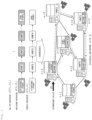
- Fig. 1 shows an example of embedding a service in a physical network.
- the example shown in Fig. 1 shows a case in which a first service g(V 1 , E 1 ) composed of start point ⁇ VNF2 ⁇ VNF3 ⁇ VNF4 ⁇ end point, a second service g(V 2 , E 2 ) composed of start point ⁇ VNF1 ⁇ VNF2 ⁇ VNF3 ⁇ end point, and the like are embedded in a physical network g(N,L).
- the first service g (V 1 , E 1 ) is embedded in physical node 3 ⁇ physical node 5 ⁇ physical node 6 ⁇ physical node 2 ⁇ physical node 4.
- the second service g(V 2 , E 2 ) is embedded in physical node 1 ⁇ physical node 3,physical node 4,physical node 2,physical node 6.
- ⁇ s is an amount of traffic generated by the sth service (hereinafter also referred to as a "service s").
- the amount of traffic ⁇ s includes, for example, the data transfer rate bps.
- the amount of traffic ⁇ s will be obtained as a prediction value using some kind of prediction method. That is to say, it is necessary to consider the embedding problem of the virtual network, based on the uncertainty of the prediction value of the amount of traffic ⁇ s .
- a method of building a time series model such as an autoregressive model which predicts a future amount of traffic from time series data of a past amount of traffic and obtaining a prediction value of a future amount of traffic from this time series model is exemplified.
- a method of using the average and variance of the amount of traffic for the past several days as prediction values can be considered.
- renewable energy and contracted power are assumed to be the power sources supplied to each physical node. Since the amount of power supplied by renewable energy is affected by the natural environment or the like, there is uncertainty in the prediction value. For this reason, there is also uncertainty in the maximum amount of power ⁇ n which is expected to be used by each physical node n (hereinafter referred to as a "maximum amount of power to be used"). That is to say, it is necessary to consider the problem of embedding a virtual network, taking into account the uncertainty of the maximum amount of power to be used ⁇ n . In the following, it is assumed that there is uncertainty in the maximum amount of power consumption of a physical node for which a command value for an amount of power consumption is not provided, that is, ⁇ n n ⁇ N r ⁇
- ⁇ ⁇ s ⁇ R + represents the nominal value of traffic generated using the service s
- ⁇ ⁇ n ⁇ R + represents the nominal value of the maximum amount of power to be used using the physical node n.
- the nominal value refers to a reference value, and for example, a statistical index such as an average value or a median value may be used.
- ⁇ s ⁇ R + is the deviation from the nominal value of the amout of traffic generated using the service s and ⁇ n ⁇ R + is the deviation from the nominal value of the maximum amount of power consumption of the physical node n which are parameters describing uncertainty.
- the parameter ⁇ ⁇ is a parameter which adjusts how much deviation exists from the nominal value.
- the parameter ⁇ ⁇ is a parameter that adjusts how much deviation from the nominal value exists.
- a virtual network embedding problem which minimizes the total cost of the entire virtual network with respect to the uncertainty of the amount of traffic and the uncertainty of the maximum amount of power to be used by physical nodes described by the above uncertainty sets (1) and (2) is formulated as the following 2-stage robust optimization problem.
- x n v,s is a binary variable, which takes 1 in a case in which VNF v ⁇ V s of service s is assigned to the physical node nGN and 0 in the other cases.
- assigning a VNF to a physical node may be expressed as "arranging a VNF on a physical node".
- y l e,s ⁇ R (l is a lowercase letter L) is a continuous variable which takes a value from 0 to 1 and represents the ratio of embedding the virtual link e ⁇ E s of the service s into the physical link lEL.
- f 1 (x n v,s ) and f 2 (y l e,s ) are functions defined below.
- f 1 (x n v,s ) represents the node power congestion rate and f 2 (y l e,s ) represents the link congestion rate.
- Equation (3b) represents the power consumption constraint at a physical node given a command value relating to an amount of power consumption and d n v,s is the power consumption coefficient when VNF v ⁇ V s in service s is assigned to physical node n.
- Expression (3b) is an equation and assumes that the amount of power consumption on the left side completely matches the command value p n , the present invention is not limited thereto.
- the inequality may be provided so that the power consumption on the left side falls within a certain range (that is, falls within certain upper and lower limit values).
- this embodiment can be similarly applied.
- Inequation (3c) represents a constraint on the maximum amount of power to be used in a physical node to which a command value relating to an amount of power consumption is not provided. Equation (3d) expresses that each VNF of each service can only be assigned to one physical node. On the other hand, Inequation (3e) means that a plurality of VNFs cannot be assigned to one physical node in one service. Note that, although the constraint conditions of (3e) are seemingly severe and seems to narrow the scope of practical application, it becomes possible to assign two or more VNFs to one physical node, for example, by treating a combination of two or more VNFs to be assigned to a certain physical node as one new VNF.
- Inequation (5b) is a capacity constraint for physical links and ⁇ l (l is lower case L) represents the maximum capacity of physical link lEL.
- Inequation (5c) is a constraint relating to the delay time required for processing each service s, in which q l e,s represents a delay time coefficient and T represents an upper limit value of delay time.
- VNF allocation x n v,s which minimizes the node power congestion rate f 1 (x n v,s ) is determined for a scenario of a case in which the amount of traffic ⁇ s is unknown and the maximum amount of power to be ⁇ n is the worst.
- the virtual link embedding ratio y l e,s (that is, path) which minimizes the link congestion rate f 2 (y l e,s ) is determined, in which the amount of traffic ⁇ s is known.
- a solution algorithm for the 2-stage robust optimization problem formulated in (3a) to (3f) and (5a) to (5d) is constructed, based on the column-and-constraint generation (C&CG) method.
- This C&CG method is an algorithm which obtains the solution of the original problem by decomposing the original problem into a master problem and a sub-problem and solving them alternately.
- (3a) to (3f) are hereinafter collectively described as (3).
- (5a) to (5d) are collectively described as (5). The same method needs to be used for other formula numbers when a plurality of expression numbers are described together.
- Step K The master problem in Step K is defined as follows. min x n v , s , r 1 > 0 r 1 6 a s . t . r 1 ⁇ 1 ⁇ ⁇ n ⁇ ⁇ n ⁇ s ⁇ S ⁇ v ⁇ V s d n v , s x n v , s + 1 ⁇ l ⁇ s ⁇ S ⁇ e ⁇ E s ⁇ s k y l e , s k , ⁇ n ⁇ N , ⁇ k ⁇ K 6 b ⁇ s ⁇ S ⁇ e ⁇ E s ⁇ s k y l e , s k ⁇ ⁇ l , ⁇ l ⁇ L , ⁇ k ⁇ K 6 c ⁇ l ⁇ L ⁇ e ⁇ E q e , s y l e , c
- ⁇ s (k) is the solution of the subproblem (which will be described later) obtained up to Step K-1.
- the optimal solution of the master problem is x n * v,s (K),r 1 *(K) and the lower bound for the optimal solution of original problems (3) and (5) is ⁇ LB (K).
- ⁇ LB K r 1 ⁇ K is established.
- x n * v,s (K) found in the master problem is used in the sub-problem in Step K.
- y l e,s (k) is also solved as a decision variable.
- Step K the sub-problem in Step K is defined as follows. [Math. 12] max ⁇ s ⁇ ⁇ s min y l e , s ⁇ Y ⁇ s , x n ⁇ v , s K f 2 y l e , s
- the sub-problem (7) above is a bilevel optimization problem and the objective function is not linear. Thus, it is difficult to solve it in of a current form thereof.
- f 2 (y l e,s ) which is the maximum value acquisition function into a linear constraint
- [Math. 13] max ⁇ s ⁇ ⁇ s min y l e , s ⁇ Y ⁇ s , x n ⁇ v , s K , r 2 > 0 r 2 s . t .
- ⁇ 1,l , ⁇ 2,l , ⁇ 3,l , ⁇ n e,s , and ⁇ l e,s represent the constraint conditions of (8), (5b), (5c), (5d), and dual variables for y l e,s ⁇ 1, respectively.
- the optimization problem (9) is a non-linear optimization problem because there is a product of ⁇ s and ⁇ 1,l and a product of ⁇ s and ⁇ 2,l .
- the maximization problem (9) is solved using the principal-dual interior point method.
- the optimal solution to the maximization problem (9) will be ⁇ s *(K) and the objective function value corresponding to this optimal solution will be Q(K).
- FIG. 2 is a diagram illustrating an example of the hardware configuration of the control apparatus 10 according to the present embodiment.
- the control apparatus 10 is realized by the hardware configuration of a general computer or a computer system and includes an input device 101, a display device 102, an external I/F 103, a communication I/F 104, a processor 105, and a memory device 106. Each of these pieces of hardware is communicatively connected using a bus 107.
- the input device 101 is, for example, a keyboard, a mouse, a touch panel, or the like.
- the display device 102 is, for example, a display or the like. Note that the control apparatus 10 may not include, for example, at least one of the input device 101 and the display device 102.
- the external I/F 103 is an interface with an external device such as a recording medium 103a.
- the control apparatus 10 can read and write data on the recording medium 103a via the external I/F 103.
- the recording medium 103a include a compact disc (CD), a digital versatile disk (DVD), a secure digital (SD) memory card), and a universal serial bus (USB) memory card.
- the communication I/F 104 is an interface through which the control apparatus 10 is connected to a communication network.
- the processor 105 include various arithmetic units such as a central processing unit (CPU) and a graphics processing unit (GPU).
- the memory device 106 includes various storage devices such as a hard disk drive (HDD), a solid state drive (SSD), a random access memory (RAM), a read only memory (ROM), and a flash memory.
- control apparatus 10 By providing the hardware configuration illustrated in Fig. 2 , the control apparatus 10 according to the embodiment can realize virtual network control processing which will be described later. Note that the hardware configuration illustrated in Fig. 2 is an example and the control apparatus 10 may have other hardware configurations. For example, the control apparatus 10 may have a plurality of processors 105, have a plurality of memory devices 106, and have various pieces of hardware (not shown).
- FIG. 3 is a diagram illustrating an example of the functional configuration of the control apparatus 10 according to the embodiment.
- the control apparatus 10 has a prediction value collection part 201, a physical network information collection part 202, a command value acquisition part 203, a control solution calculation part 204, and a control part 205.
- Each of these parts is implemented by processing in which one or more programs installed in the control apparatus 10 cause the processor 105 to execute.
- the prediction value collection part 201 collects a prediction value of an amount of traffic of each service and the prediction value of a maximum amount of power to be used in each physical node (here, a physical node to which a command value relating to the amount of power consumption is not provided). That is to say, the prediction value collection part 201 acquires a nominal value of the amount of traffic of each service and a deviation thereof and a nominal value of the maximum amount of power consumption and a deviation thereof in each physical node to which a command value relating to the amount of power consumption is not provided.
- the prediction value of the amount of traffic of each service and the prediction value of the maximum amount of power consumption in each physical node are obtained by a prediction algorithm or the like using a time-series model.
- the prediction value collection part 201 acquires the prediction value of the amount of traffic up to one day ahead and the prediction value of the maximum amount of power consumption using some kind of prediction algorithm.
- these prediction values correspond to an average value and a variance of a certain sampling interval.
- the average value may be set as the nominal value and the variance may be set as the deviation of the nominal value.
- the sampling interval is a time interval such as one minute or one hour which is preset in accordance with control specifications for VNF allocation and path determination.
- the physical network information collection part 202 collects information relating to the topology of the physical network and various parameters (for example, power consumption coefficient or the like).
- control solution calculation part 204 Note that the information and various parameters collected using the physical network information collection part 202 are passed to the control solution calculation part 204.
- the command value acquisition part 203 acquires a command value relating to an amount of power consumption. That is to say, the command value acquisition part 203 acquires information indicating a physical node to which a command value relating to an amount of power consumption is provided and the command value.
- command value acquired using the command value acquisition part 203 is passed to the control solution calculation part 204.
- the control solution calculation part 204 performs an algorithm to solve the 2-stage robust optimization problems (3) and (5) using the information collected using the prediction value collection part 201, the information collected using the physical network information collection part 202, and the command value acquired using the command value acquisition part 203. That is to say, the control solution calculation part 204 calculates the VNF allocation x n v,s by alternately and repeatedly solving the master problem (6) and the sub-problem (9) in the first step, and then calculates the path determination y l e,s by solving the sub-problem (7) in the second stage. Thus, the VNF allocation x n v,s and the path determination y l e,s representing the optimal control solution of the original problems (3) and (5) are obtained.
- the control solution calculation part 204 includes a first problem solving part 211 and a second problem solving part 212.
- the first problem solving part 211 calculates the solution to the master problem (6) and also calculates the lower bounds of the optimal solutions to the original problems (3) and (5).
- the second problem solving part 212 calculates the solutions of the sub-problem (9) and the sub-problem (7) and also calculates the upper bounds of the optimal solutions of the original problems (3) and (5). Note that, for example, when performing the above-mentioned scheduling, the control solution calculation part 204 can divide the 2-stage robust optimization problems (3) and (5) into each sampling time interval, and then perform the solution algorithm for each independently.
- the control part 205 controls the virtual network using the control solution calculated using the control solution calculation part 204.
- the VNF allocation and the path determination represented by the optimal control solution are embedded in the physical network (that is, changed to the optimal VNF allocation and the path determination).
- the VNF allocation and the path determination are scheduled for one day in the future has been described as an example, this is one example of application and is not limited thereto.
- it can be similarly applied when calculating optimal VNF allocation and paths in real time and dynamically controlling a virtual network.
- the control solution calculation part 204 may perform a solution-finding algorithm each time the command value is collected/obtained and the control part 205 may update the VNF allocation and path.
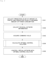
- the prediction value collection part 201 collects a prediction value of the amount of traffic for each service (nominal value and a deviation thereof) and a prediction value of maximum power consumption (nominal value and a deviation thereof) for each physical node (physical nodes for which a command value relating to an amount of power consumption is not provided) (Step S101)
- the physical network information collection part 202 collects information relating to the topology of the physical network and various parameters (for example, power consumption coefficient or the like) (Step S102).
- various parameters for example, power consumption coefficient or the like
- the command value acquisition part 203 acquires the command value for the physical node to which the command value relating to an amount of power consumption has been provided (Step S103).
- control solution calculation part 204 performs an algorithm for solving the 2-stage robust optimization problems (3) and (5) using the information collected or obtained in Steps S101 to S103 above and calculates the optimal control solution (Step S104). Note that details of this step will be described later.
- control part 205 controls the virtual network using the control solution calculated in Step S104 above (Step S105).
- Fig. 5 is a flowchart for describing an example of a flow of control solution calculation processing according to the embodiment.
- the initial value ⁇ s (0) may be set to any value belonging to ⁇ s .
- the parameter ⁇ >0 for determining the end condition of the first stage may be set to a finite value.
- control solution calculation part 204 solves the master problem (6) using the first problem solving part 211 and acquires the optimal solutions x n * v,s (K), r 1 *(K), and ⁇ LB (K) (Step S202).
- control solution calculation part 204 uses a preset parameter ⁇ (or the parameter ⁇ set in Step S201 above) to determine whether ⁇ UB (K)- ⁇ LB (K) ⁇ is satisfied (Step S204).
- Step S204 When it is not determined in Step S204 that ⁇ UB (K)- ⁇ LB (K) ⁇ is satisfied, the control solution calculation part 204 updates Step K by adding 1 to Step K (Step S205) and returns to Step S202. Thus, Steps S202 to S203 are repeatedly performed until ⁇ UB (K)- ⁇ LB (K) ⁇ is satisfied.
- Step S204 when it is determined in Step S204 above that ⁇ UB (K)- ⁇ LB (K) ⁇ is satisfied, the control solution calculation part 204 fixes ⁇ s *(K), and then uses the second problem solving part 212 to solve the sub-problem (7) to acquire the optimal solution y l * e,s (Step S206) .
- the control apparatus 10 can realize virtual network control (VNF allocation and path determination) which robustly satisfies command values against the uncertainties of the amount of traffic and the uncertainties of renewable energy.
- VNF allocation and path determination virtual network control
- VNFs are assigned and paths are determined by taking into account the fact that there are uncertainties in predictions relating to an amount of traffic and an amount of renewable energy power.
- predictions relating to an amount of traffic and an amount of renewable energy power.
- it is possible to robustly prevent deterioration of communication performance and congestion which may occur due to the influence of prediction errors, increased costs due to purchasing insufficient power, and increased environmental burden due to a decline in the utilization rate of renewable energy.
- the directive relating to an amount of power consumption it becomes possible, for example, to respond to demand response requests or to generate the amount of power sold necessary for conducting power market transactions.
- the virtual network control process (particularly the control solution calculation process) according to the embodiment is a solution algorithm based on the theory of mathematical optimization called 2-stage robust optimization.
- This theory performs two-step robust optimization based on a decision-making process and is known to yield solutions with lower conservatism than simple robust optimization. This means that, even if there are errors in predicting an amount of traffic and renewable energy, it is possible to perform low-maintenance VNF allocation and route determination while suppressing the deterioration of communication performance and the occurrence of congestion, as well as preventing the purchase costs of insufficient power and the decline in the utilization rate of renewable energy.
Landscapes
- Engineering & Computer Science (AREA)
- Computer Networks & Wireless Communication (AREA)
- Signal Processing (AREA)
- Data Exchanges In Wide-Area Networks (AREA)
Abstract
Description
- The present invention relates to a control apparatus, a control method, and a program.
- In recent years, with the development of network function visualization (NFV) which is a virtualization technique, it is possible to provide a vast variety of network services by flexibly combining a wide variety of virtual network resources (VR: Virtual Resource) and virtual network functions (VNFs). In order to provide such services, appropriately allocating VRs and VNFs to physical resources for each service is required. In addition, appropriately determining the end-to-end path for sending the service to ensure desired communication performance (for example, communication delay time or the like) is required. For this reason, many control methods for VNF allocation and path determination under an NFV environment have been studied and reported.
- Incidentally, in recent years, there has been a worldwide movement to introduce renewable energy to reduce the environmental load. As problems in operating a virtual network using renewable energy, there is the fact that it is impossible to supply the desired power generation amount which matches the demand amount, resulting in oversupply or undersupply due to the uncertainty of the weather. On the other hand, for example, NPL 1 proposes a virtual network control method which robustly prevents oversupply or undersupply on the assumption that there is uncertainty in the amount of traffic as well as the amount of electricity from renewable energy.
- [NPL 1] Kengo URATA, Ryota NAKAMURA, Shigeaki HARADA, Robust VNF Allocation in Virtual Networks under Uncertainty of Traffic Demands and Renewable Energy Resources, IEICE Technical Report, vol. 120, No. 414, IN2020-57, pp. 19-24, March 2021.
- However, the method proposed in the above-described
NPL 1 does not perform virtual network control under the condition in which any command relating to an amount of power consumption is provided based on the premise of adjusting the closed supply and demand balance within the virtual network. - For example, the case in which a power system (microgrid) which operates a virtual network cooperates with the power grid and receives a request for demand response is considered. At this time, although it is necessary to generate surplus electricity in the region which has received the command in the communication network, the method proposed in the above-described
NPL 1 is based on the premise of preventing oversupply, and thus cannot satisfy that request. - Also, for example, the case in which a telecommunications network operator enters the electricity market is considered. In this case, it is assumed that, for each power sales transaction, an appropriate amount of power to be sold will be determined according to the bid price in the market. On the premise of this, the method proposed in the above-described
NPL 1 cannot generate surplus power sufficient to generate the amount of power sold and it is considered that an economic loss may occur. - Therefore, it is considered necessary to make VNF allocation and routing robust against uncertainties in both an amount of traffic and renewable energy when given any command relating to an amount of power consumption in the communication network.
- An embodiment of the present invention was made in view of the above points, and an object of the present invention is to implement virtual network control which is robust against the uncertainties of the amount of traffic and the uncertainties of renewable energy and which satisfies commands relating to an amount of power consumption.
- In order to achieve the above object, a control apparatus according to an embodiment is a control apparatus for embedding a virtual network in a physical network, the virtual network enabling service provision, the control apparatus including: a first acquisition part configured to acquire a prediction value of an amount of traffic of a service and a prediction value of an amount of power consumption of a physical node to which a command value relating to the amount of power consumption is not provided, from among physical nodes configuring a physical network; a second acquisition part configured to acquire information relating to the physical network; a third acquisition part configured to acquire the command value provided to at least some of physical nodes configuring the physical network; a solution calculation part configured to calculate an optimal solution to a 2-stage robust optimization problem relating to allocation of virtual nodes configuring the virtual network to physical nodes and determination of paths between the virtual nodes, with a constraint condition that an amount of power consumption of a physical node to which the command value is provided satisfies the command value, based on the prediction value of the amount of traffic, the prediction value of the amount of power consumption, information relating to the physical network, and the command value; and a control part configured to control a virtual network embedded in the physical network, based on allocation of the virtual node and determination of a path represented by the optimal solution. Advantageous Effects of Invention
- It is possible to realize virtual network control which is robust to the uncertainties of the amount of traffic and the uncertainties of renewable energy and satisfies commands relating to an amount of power consumption.
-
- [
Fig. 1] Fig. 1 is a diagram for explaining an example of embedding a service into a physical network. - [
Fig. 2] Fig. 2 is a diagram illustrating an example of a hardware configuration of a control apparatus according to an embodiment. - [
Fig. 3] Fig. 3 is a diagram illustrating an example of a functional configuration of the control apparatus according to the embodiment - [
Fig. 4] Fig. 4 is a flowchart for describing an example of a flow of virtual network control processing according to the embodiment. - [
Fig 5] Fig. 5 is a flowchart for describing an example of a flow of control solution calculation processing according to the embodiment. - An embodiment of the present invention will be described below. In the embodiment, a
control apparatus 10 which is capable of realizing virtual network control (VNF allocation and path determination) which is robust against the uncertainties of the amount of traffic and the uncertainties of renewable energy and satisfies commands relating to an amount of power consumption will be described. Here, hereinafter, in order to distinguish it from a virtual network, a network composed of physical nodes and physical links which require power will also be referred to as a physical network. On the other hand, a network in which VNFs are virtual nodes and routes between VNFs are virtual links is also called a virtual network. Furthermore, it is assumed that the physical nodes are, for example, bases such as data centers and that command values relating to an amount of power consumption are provided to at least some of the physical nodes in the physical network. Note that the command value relating to an amount of power consumption is a command specifying the power consumption of the physical node. Such a command value is provided to the physical node, for example, in response to a request for demand response, a request to secure the amount of power to be sold, or the like to secure the amount of power required for satisfying the request. - The theoretical configuration of the embodiment will be explained below.
- A virtual network defined by a combination of a starting point (for example, a site having a user accommodated therein) and an end point (for example, a site in which a server is installed) and a VNF (for example, firewall or the like) used at the time of providing a service is equated with a service provided using this virtual network (service function chaining: SFC) and the problem of embedding Ns services into a physical network is considered. That is to say, the problem of embedding Ns virtual networks, each providing Ns services, into a physical network is considered. Here, a virtual link can be divided into any number of paths and can be embedded in one or more physical links connected to a physical node at any ratio.
- It is assumed that the topology of the physical network is expressed as g(N,L), N represents a set of physical nodes, and L represents a set of physical links. In addition, it is assumed that In⊆L is a set of physical links flowing into physical node nGN and On⊆L is a set of physical links flowing out from physical node nGN. Also, it is assumed that S is a set of services and V is a set relating to a type of VNF. It is assumed that Nr⊆N is a set of physical nodes to which a command value relating to an amount of power consumption is provided,

- At this time, each service is written as g(Vs,Es). Vs⊆V is a VNF set of the s-th service and Es is a virtual link set of the sth service. Note that it is assumed that V also includes the start point node and the end point node of the service.
- In addition, the virtual link e∈Es of the s-th service is also expressed interchangeably as (vso, vd). Here, vso represents a start node of virtual link e and vd represents an end node of virtual link e.
-
Fig. 1 shows an example of embedding a service in a physical network. The example shown inFig. 1 shows a case in which a first service g(V1, E1) composed of start point→VNF2→VNF3→VNF4 →end point, a second service g(V2, E2) composed of start point→VNF1→VNF2→VNF3→end point, and the like are embedded in a physical network g(N,L). Specifically, the first service g (V1, E1) is embedded inphysical node 3→physical node 5→physical node 6→physical node 2→physical node 4. Similarly, the second service g(V2, E2) is embedded inphysical node 1→physical node 3,physical node 4,physical node 2,physical node 6. - It is assumed that λs is an amount of traffic generated by the sth service (hereinafter also referred to as a "service s"). The amount of traffic λs includes, for example, the data transfer rate bps. When performing future VNF allocation and path determination, it is assumed that the amount of traffic λs will be obtained as a prediction value using some kind of prediction method. That is to say, it is necessary to consider the embedding problem of the virtual network, based on the uncertainty of the prediction value of the amount of traffic λs. Note that, although various methods can be considered for predicting the amount of traffic λs, for example, a method of building a time series model such as an autoregressive model which predicts a future amount of traffic from time series data of a past amount of traffic and obtaining a prediction value of a future amount of traffic from this time series model is exemplified. In addition, for example, a method of using the average and variance of the amount of traffic for the past several days as prediction values can be considered.
- Furthermore, renewable energy and contracted power are assumed to be the power sources supplied to each physical node. Since the amount of power supplied by renewable energy is affected by the natural environment or the like, there is uncertainty in the prediction value. For this reason, there is also uncertainty in the maximum amount of power µn which is expected to be used by each physical node n (hereinafter referred to as a "maximum amount of power to be used"). That is to say, it is necessary to consider the problem of embedding a virtual network, taking into account the uncertainty of the maximum amount of power to be used µn. In the following, it is assumed that there is uncertainty in the maximum amount of power consumption of a physical node for which a command value for an amount of power consumption is not provided, that is,

- Under the above assumptions, a robust virtual network embedding problem against uncertainties of the amount of traffic and uncertainties of renewable energy is formulated. In order to prepare for this, first, the uncertainty of the amount of traffic and the uncertainty of the maximum amount of power to be used by each physical node are described as the following polyhedron set.


- In the above uncertainty set (1), the parameter γλ is a parameter which adjusts how much deviation exists from the nominal value. Similarly, in the uncertainty set (2) above, the parameter γµ is a parameter that adjusts how much deviation from the nominal value exists. These parameters γλ and γµ can also be said to be parameters which define the size of the uncertainty set.
- With the above preparations, a virtual network embedding problem which minimizes the total cost of the entire virtual network with respect to the uncertainty of the amount of traffic and the uncertainty of the maximum amount of power to be used by physical nodes described by the above uncertainty sets (1) and (2) is formulated as the following 2-stage robust optimization problem.

- Here, xn v,s is a binary variable, which takes 1 in a case in which VNF v∈Vs of service s is assigned to the physical node nGN and 0 in the other cases. Note that assigning a VNF to a physical node may be expressed as "arranging a VNF on a physical node".
- Furthermore, yl e,s∈R (l is a lowercase letter L) is a continuous variable which takes a value from 0 to 1 and represents the ratio of embedding the virtual link e∈Es of the service s into the physical link lEL. In the objective function (3a), f1(xn v,s) and f2(yl e,s) are functions defined below.

- The above f1(xn v,s) represents the node power congestion rate and f2(yl e,s) represents the link congestion rate.
- Equation (3b) represents the power consumption constraint at a physical node given a command value relating to an amount of power consumption and dn v,s is the power consumption coefficient when VNF v∈Vs in service s is assigned to physical node n. Note that, although Expression (3b) is an equation and assumes that the amount of power consumption on the left side completely matches the command value pn, the present invention is not limited thereto. In addition, for example, the inequality may be provided so that the power consumption on the left side falls within a certain range (that is, falls within certain upper and lower limit values). Thus, even when using a relaxed command value such as suppressing the amount of power consumption within a certain range (for example, command value with upper and lower limits designated for an amount of energy consumption) as the command value relating to the power consumption, this embodiment can be similarly applied.
- Inequation (3c) represents a constraint on the maximum amount of power to be used in a physical node to which a command value relating to an amount of power consumption is not provided. Equation (3d) expresses that each VNF of each service can only be assigned to one physical node. On the other hand, Inequation (3e) means that a plurality of VNFs cannot be assigned to one physical node in one service. Note that, although the constraint conditions of (3e) are seemingly severe and seems to narrow the scope of practical application, it becomes possible to assign two or more VNFs to one physical node, for example, by treating a combination of two or more VNFs to be assigned to a certain physical node as one new VNF.
- Furthermore, a set y(λs,xn v,s) of yl e,s which can be obtained when the amount of traffic λs and xn v,s are fixed is described as follows:
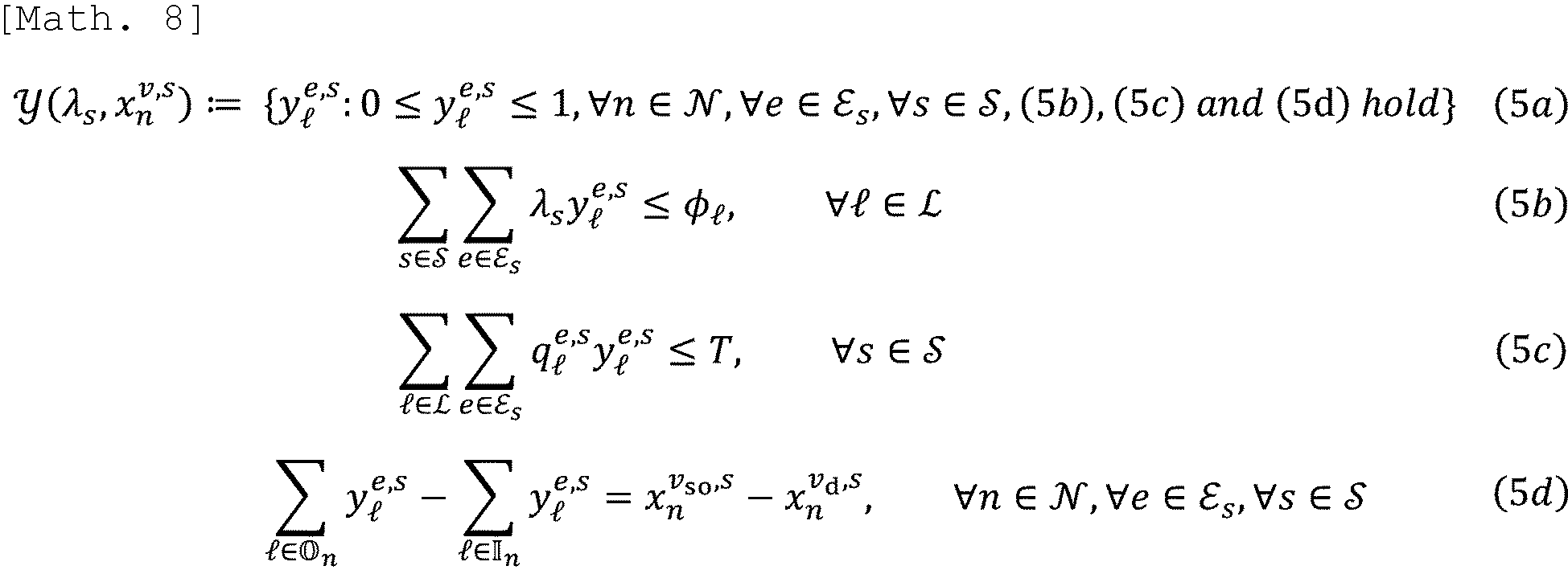
- . Here, Inequation (5b) is a capacity constraint for physical links and ϕl (l is lower case L) represents the maximum capacity of physical link lEL. Furthermore, Inequation (5c) is a constraint relating to the delay time required for processing each service s, in which ql e,s represents a delay time coefficient and T represents an upper limit value of delay time.
- The solutions of the 2-stage robust optimization problems formulated in (3a) to (3f) and (5a) to (5d) are calculated in two stages. First, in the first stage, VNF allocation xn v,s which minimizes the node power congestion rate f1(xn v,s) is determined for a scenario of a case in which the amount of traffic λs is unknown and the maximum amount of power to be µn is the worst. In the second stage, the virtual link embedding ratio yl e,s (that is, path) which minimizes the link congestion rate f2(yl e,s) is determined, in which the amount of traffic λs is known. Thus, it is possible to obtain a control solution (that is, VNF allocation xn v,s and path determination yl e,s) which is robust to the uncertainties of the amount of traffic and the uncertainties of renewable energy and satisfies the command relating to an amount of power consumption. The specific solution procedure will be explained below.
- A solution algorithm for the 2-stage robust optimization problem formulated in (3a) to (3f) and (5a) to (5d) is constructed, based on the column-and-constraint generation (C&CG) method. This C&CG method is an algorithm which obtains the solution of the original problem by decomposing the original problem into a master problem and a sub-problem and solving them alternately. Note that (3a) to (3f) are hereinafter collectively described as (3). Similarly, (5a) to (5d) are collectively described as (5). The same method needs to be used for other formula numbers when a plurality of expression numbers are described together.
- The master problem in Step K is defined as follows.

- Here, in the above problem, λs(k) is the solution of the subproblem (which will be described later) obtained up to Step K-1. In addition, K in cursive is as follows:

- . Hereinafter, it is assumed that the optimal solution of the master problem is xn*v,s(K),r1*(K) and the lower bound for the optimal solution of original problems (3) and (5) is ψLB(K). At this time,

- Next, the sub-problem in Step K is defined as follows.
[Math. 12]
- In the above problem, it is assumed that there exists an optimal value (λs*(K),yl*e,s(K)) such that the objective function has a finite value. That is to say, it is assumed that sub-problem (7) is executable for any solution of the master problem. Note that, when the sub-problem (7) is infeasible for some solution of the master problem, for example, the
control apparatus 10 may output information indicating that the virtual network cannot be embedded. - The sub-problem (7) above is a bilevel optimization problem and the objective function is not linear. Thus, it is difficult to solve it in of a current form thereof. Thus, in order to avoid this, first, by converting f2(yl e,s) which is the maximum value acquisition function into a linear constraint,
[Math. 13]


- In the above maximization problem (9), π1,l,π2,l,π3,l,ξn e,s, and θl e,s represent the constraint conditions of (8), (5b), (5c), (5d), and dual variables for yl e,s≤1, respectively. The optimization problem (9) is a non-linear optimization problem because there is a product of λs and π1,l and a product of λs and π2,l. In this embodiment, the maximization problem (9) is solved using the principal-dual interior point method. Hereinafter, the optimal solution to the maximization problem (9) will be λs*(K) and the objective function value corresponding to this optimal solution will be Q(K). At this time, the upper bound of the optimal solution of the original problem (3) is defined as ψUB(K), and

- By alternately and repeatedly solving the above master problem (6) and the sub-problem (9), it is guaranteed that the upper and lower bounds asymptotically converge to the optimal solution of the original problem (3).
- A hardware configuration of the
control apparatus 10 according to the embodiment will be explained below with reference toFig. 2. Fig. 2 is a diagram illustrating an example of the hardware configuration of thecontrol apparatus 10 according to the present embodiment. - As illustrated in
Fig. 2 , thecontrol apparatus 10 according to the embodiment is realized by the hardware configuration of a general computer or a computer system and includes aninput device 101, adisplay device 102, an external I/F 103, a communication I/F 104, aprocessor 105, and amemory device 106. Each of these pieces of hardware is communicatively connected using abus 107. - The
input device 101 is, for example, a keyboard, a mouse, a touch panel, or the like. Thedisplay device 102 is, for example, a display or the like. Note that thecontrol apparatus 10 may not include, for example, at least one of theinput device 101 and thedisplay device 102. - The external I/
F 103 is an interface with an external device such as arecording medium 103a. Thecontrol apparatus 10 can read and write data on therecording medium 103a via the external I/F 103. Note that examples of therecording medium 103a include a compact disc (CD), a digital versatile disk (DVD), a secure digital (SD) memory card), and a universal serial bus (USB) memory card. - The communication I/
F 104 is an interface through which thecontrol apparatus 10 is connected to a communication network. Examples of theprocessor 105 include various arithmetic units such as a central processing unit (CPU) and a graphics processing unit (GPU). Examples of thememory device 106 includes various storage devices such as a hard disk drive (HDD), a solid state drive (SSD), a random access memory (RAM), a read only memory (ROM), and a flash memory. - By providing the hardware configuration illustrated in
Fig. 2 , thecontrol apparatus 10 according to the embodiment can realize virtual network control processing which will be described later. Note that the hardware configuration illustrated inFig. 2 is an example and thecontrol apparatus 10 may have other hardware configurations. For example, thecontrol apparatus 10 may have a plurality ofprocessors 105, have a plurality ofmemory devices 106, and have various pieces of hardware (not shown). - A functional configuration of the
control apparatus 10 according to the embodiment will be described below with reference toFig. 3. Fig. 3 is a diagram illustrating an example of the functional configuration of thecontrol apparatus 10 according to the embodiment. - As illustrated in
Fig. 3 , thecontrol apparatus 10 according to the embodiment has a predictionvalue collection part 201, a physical networkinformation collection part 202, a commandvalue acquisition part 203, a controlsolution calculation part 204, and acontrol part 205. Each of these parts is implemented by processing in which one or more programs installed in thecontrol apparatus 10 cause theprocessor 105 to execute. - The prediction
value collection part 201 collects a prediction value of an amount of traffic of each service and the prediction value of a maximum amount of power to be used in each physical node (here, a physical node to which a command value relating to the amount of power consumption is not provided). That is to say, the predictionvalue collection part 201 acquires a nominal value of the amount of traffic of each service and a deviation thereof and a nominal value of the maximum amount of power consumption and a deviation thereof in each physical node to which a command value relating to the amount of power consumption is not provided. - In the embodiment, it is assumed that the prediction value of the amount of traffic of each service and the prediction value of the maximum amount of power consumption in each physical node are obtained by a prediction algorithm or the like using a time-series model. For example, when scheduling VNF allocation and path determination for a future day, the prediction
value collection part 201 acquires the prediction value of the amount of traffic up to one day ahead and the prediction value of the maximum amount of power consumption using some kind of prediction algorithm. Here, it is assumed that these prediction values correspond to an average value and a variance of a certain sampling interval. In this case, the average value may be set as the nominal value and the variance may be set as the deviation of the nominal value. Note that the sampling interval is a time interval such as one minute or one hour which is preset in accordance with control specifications for VNF allocation and path determination. - Note that the nominal value and a deviation thereof collected using the prediction
value collection part 201 are passed to the controlsolution calculation part 204. - The physical network
information collection part 202 collects information relating to the topology of the physical network and various parameters (for example, power consumption coefficient or the like). - Note that the information and various parameters collected using the physical network
information collection part 202 are passed to the controlsolution calculation part 204. - The command
value acquisition part 203 acquires a command value relating to an amount of power consumption. That is to say, the commandvalue acquisition part 203 acquires information indicating a physical node to which a command value relating to an amount of power consumption is provided and the command value. - Note that the command value acquired using the command
value acquisition part 203 is passed to the controlsolution calculation part 204. - The control
solution calculation part 204 performs an algorithm to solve the 2-stage robust optimization problems (3) and (5) using the information collected using the predictionvalue collection part 201, the information collected using the physical networkinformation collection part 202, and the command value acquired using the commandvalue acquisition part 203. That is to say, the controlsolution calculation part 204 calculates the VNF allocation xn v,s by alternately and repeatedly solving the master problem (6) and the sub-problem (9) in the first step, and then calculates the path determination yl e,s by solving the sub-problem (7) in the second stage. Thus, the VNF allocation xn v,s and the path determination yl e,s representing the optimal control solution of the original problems (3) and (5) are obtained. - Here, the control
solution calculation part 204 includes a firstproblem solving part 211 and a secondproblem solving part 212. The firstproblem solving part 211 calculates the solution to the master problem (6) and also calculates the lower bounds of the optimal solutions to the original problems (3) and (5). The secondproblem solving part 212 calculates the solutions of the sub-problem (9) and the sub-problem (7) and also calculates the upper bounds of the optimal solutions of the original problems (3) and (5). Note that, for example, when performing the above-mentioned scheduling, the controlsolution calculation part 204 can divide the 2-stage robust optimization problems (3) and (5) into each sampling time interval, and then perform the solution algorithm for each independently. - The
control part 205 controls the virtual network using the control solution calculated using the controlsolution calculation part 204. Thus, the VNF allocation and the path determination represented by the optimal control solution are embedded in the physical network (that is, changed to the optimal VNF allocation and the path determination). - Note that, although a case in which the VNF allocation and the path determination are scheduled for one day in the future has been described as an example, this is one example of application and is not limited thereto. For example, it can be similarly applied when calculating optimal VNF allocation and paths in real time and dynamically controlling a virtual network. Specifically, for each sampling point, it is possible to collect the prediction value of the amount of traffic of each service and the prediction value of the maximum amount of power to be used at each physical node (here, for physical nodes for which a command value relating to an amount of power consumption is not provided). In addition, when a command value relating to power consumption can be obtained, the control
solution calculation part 204 may perform a solution-finding algorithm each time the command value is collected/obtained and thecontrol part 205 may update the VNF allocation and path. - A flow of virtual network control processing according to the embodiment will be described below with reference to
Fig. 4. Fig. 4 is a flowchart for describing an example of the flow of the virtual network control processing according to the embodiment. Note that it is assumed that the service g(Vs,Es) (s=1,...,Ns) to be embedded is provided to thecontrol apparatus 10 in advance. - First, the prediction
value collection part 201 collects a prediction value of the amount of traffic for each service (nominal value and a deviation thereof) and a prediction value of maximum power consumption (nominal value and a deviation thereof) for each physical node (physical nodes for which a command value relating to an amount of power consumption is not provided) (Step S101) - Subsequently, the physical network
information collection part 202 collects information relating to the topology of the physical network and various parameters (for example, power consumption coefficient or the like) (Step S102). Here, when the topology of the physical network and the values of various parameters have not been changed since the last collection, this step may not be performed. - Subsequently, the command
value acquisition part 203 acquires the command value for the physical node to which the command value relating to an amount of power consumption has been provided (Step S103). - Subsequently, the control
solution calculation part 204 performs an algorithm for solving the 2-stage robust optimization problems (3) and (5) using the information collected or obtained in Steps S101 to S103 above and calculates the optimal control solution (Step S104). Note that details of this step will be described later. - Also, the
control part 205 controls the virtual network using the control solution calculated in Step S104 above (Step S105). - Here, details of the control solution calculation process in Step S104 will be described with reference to
Fig. 5. Fig. 5 is a flowchart for describing an example of a flow of control solution calculation processing according to the embodiment. - First, the control
solution calculation part 204 sets Step K=0 and ψUB(0)=∞ and sets an initial value λs(0) (Step S201). Note that the initial value λs(0) may be set to any value belonging to Λs. Furthermore, at this time, the parameter ε>0 for determining the end condition of the first stage may be set to a finite value. - Subsequently, the control
solution calculation part 204 solves the master problem (6) using the firstproblem solving part 211 and acquires the optimal solutions xn*v,s(K), r1*(K), and ψLB(K) (Step S202). - Subsequently, the control
solution calculation part 204 uses the secondproblem solving part 212 to solve the sub-problem (9) and acquires the optimal solutions λs*(K) and ψUB(K) (Step S203). At this time, the controlsolution calculation part 204 updates ψUB(K) by ψUB(K)=min(ψUB(K), ψUB(K-1)). - Subsequently, the control
solution calculation part 204 uses a preset parameter ε (or the parameter ε set in Step S201 above) to determine whether ψUB(K)-ψLB(K)≦ε is satisfied (Step S204). - When it is not determined in Step S204 that ψUB(K)-ψLB(K)≤ε is satisfied, the control
solution calculation part 204 updates Step K by adding 1 to Step K (Step S205) and returns to Step S202. Thus, Steps S202 to S203 are repeatedly performed until ψUB(K)-ψLB(K)≤ε is satisfied. - On the other hand, when it is determined in Step S204 above that ψUB(K)-ψLB(K)≤ε is satisfied, the control
solution calculation part 204 fixes λs*(K), and then uses the secondproblem solving part 212 to solve the sub-problem (7) to acquire the optimal solution yl*e,s (Step S206) . - The optimal solutions xn*v,s(K) and yl*e,s are acquired from the above, and these become the optimal control solutions (optimal solutions) for the original problems (3) and (5). Note that, although it is necessary to solve sub-problem (7) in Step S206 above, this optimization problem can be easily solved because it can be reduced to a simple linear programming problem relating to yl e,s.
- As described above, under the situation in which command values relating to an amount of power consumption are provided to at least some physical nodes in the physical network, the
control apparatus 10 according to the embodiment can realize virtual network control (VNF allocation and path determination) which robustly satisfies command values against the uncertainties of the amount of traffic and the uncertainties of renewable energy. - In the virtual network control processing to realize the above virtual network control, VNFs are assigned and paths are determined by taking into account the fact that there are uncertainties in predictions relating to an amount of traffic and an amount of renewable energy power. Thus, it is possible to robustly prevent deterioration of communication performance and congestion which may occur due to the influence of prediction errors, increased costs due to purchasing insufficient power, and increased environmental burden due to a decline in the utilization rate of renewable energy. In addition, since it also satisfies the directive relating to an amount of power consumption, it becomes possible, for example, to respond to demand response requests or to generate the amount of power sold necessary for conducting power market transactions.
- Furthermore, the virtual network control process (particularly the control solution calculation process) according to the embodiment is a solution algorithm based on the theory of mathematical optimization called 2-stage robust optimization. This theory performs two-step robust optimization based on a decision-making process and is known to yield solutions with lower conservatism than simple robust optimization. This means that, even if there are errors in predicting an amount of traffic and renewable energy, it is possible to perform low-maintenance VNF allocation and route determination while suppressing the deterioration of communication performance and the occurrence of congestion, as well as preventing the purchase costs of insufficient power and the decline in the utilization rate of renewable energy.
- The present invention is not limited to the above-described specifically disclosed embodiments and various modifications and changes, combinations with known techniques or the like are possible without departing from the scope of the claims.
-
- 10
- Control apparatus
- 101
- Input device
- 102
- Display device
- 103
- External I/F
- 103a
- Recording medium
- 104
- Communication I/F
- 105
- Processor
- 106
- Memory device
- 107
- Bus
- 201
- Prediction value collection part
- 202
- Physical network information collection part
- 203
- Command value acquisition part
- 204
- Control solution calculation part
- 205
- Control part
- 211
- First problem solving part
- 212
- Second problem solving part
Claims (6)
- A control apparatus for embedding a virtual network in a physical network, the virtual network enabling service provision, the control apparatus comprising:a first acquisition part configured to acquire a prediction value of an amount of traffic of a service and a prediction value of an amount of power consumption of a physical node to which a command value relating to the amount of power consumption is not provided, from among physical nodes configuring a physical network;a second acquisition part configured to acquire information relating to the physical network;a third acquisition part configured to acquire the command value provided to at least some of physical nodes configuring the physical network;a solution calculation part configured to calculate an optimal solution to a 2-stage robust optimization problem relating to allocation of virtual nodes configuring the virtual network to physical nodes and determination of paths between the virtual nodes, with a constraint condition that an amount of power consumption of a physical node to which the command value is provided satisfies the command value, based on the prediction value of the amount of traffic, the prediction value of the amount of power consumption, information relating to the physical network, and the command value; anda control part configured to control a virtual network embedded in the physical network, based on allocation of the virtual node and determination of a path represented by the optimal solution.
- The control apparatus according to claim 1, wherein the command value is an amount of power consumption in which a physical node to which the command value is provided needs to be satisfied or a range of the amount of power consumption in which a physical node to which the command value is provided needs to satisfied.
- The control apparatus according to claim 1 or 2, wherein the prediction value of the amount of traffic is expressed by a nominal value of the amount of traffic and a deviation from the nominal value, and
the prediction value of the amount of power consumption is expressed by a nominal value of the amount of power consumption of a physical node to which the command value is not provided and a deviation from the nominal value. - The control apparatus according to any one of claims 1 to 3, wherein the solution calculation part is configured to decompose the 2-stage robust optimization problem into a master problem and a sub-problem, based on a column-and-constraint generation method, and then calculate an optimal solution relating to the allocation of the virtual nodes by alternately solving the master problem and the sub-problem in a first step, and calculate an optimal solution relating to the path determination by solving the sub-problem in a second step.
- A control method performed by a control apparatus, the control apparatus being used for embedding a virtual network in a physical network, the virtual network enabling service provision, the control method comprising:a first acquisition procedure of acquiring a prediction value of an amount of traffic of a service and a prediction value of an amount of power consumption of a physical node to which a command value relating to the amount of power consumption is not provided, from among physical nodes configuring a physical network;a second acquisition procedure of acquiring information relating to the physical network;a third acquisition procedure of acquiring the command value provided to at least some of physical nodes configuring the physical network;a solution calculation procedure of calculating an optimal solution to a 2-stage robust optimization problem relating to allocation of virtual nodes configuring the virtual network to physical nodes and determination of paths between the virtual nodes, with a constraint condition that an amount of power consumption of a physical node to which the command value is provided satisfies the command value, based on the prediction value of the amount of traffic, the prediction value of the amount of power consumption, information relating to the physical network, and the command value; anda control procedure of controlling a virtual network embedded in the physical network, based on allocation of the virtual node and determination of a path represented by the optimal solution.
- A program which causes a computer to function as the control apparatus according to any one of claims 1 to 4.
Applications Claiming Priority (1)
| Application Number | Priority Date | Filing Date | Title |
|---|---|---|---|
| PCT/JP2022/006484 WO2023157197A1 (en) | 2022-02-17 | 2022-02-17 | Control device, control method, and program |
Publications (2)
| Publication Number | Publication Date |
|---|---|
| EP4482102A1 true EP4482102A1 (en) | 2024-12-25 |
| EP4482102A4 EP4482102A4 (en) | 2026-03-25 |
Family
ID=87577942
Family Applications (1)
| Application Number | Title | Priority Date | Filing Date |
|---|---|---|---|
| EP22927099.6A Pending EP4482102A4 (en) | 2022-02-17 | 2022-02-17 | CONTROL DEVICE, CONTROL METHOD AND PROGRAM |
Country Status (4)
| Country | Link |
|---|---|
| US (1) | US12609872B2 (en) |
| EP (1) | EP4482102A4 (en) |
| JP (1) | JP7700948B2 (en) |
| WO (1) | WO2023157197A1 (en) |
Family Cites Families (3)
| Publication number | Priority date | Publication date | Assignee | Title |
|---|---|---|---|---|
| JP6721921B2 (en) * | 2017-05-30 | 2020-07-15 | 日本電信電話株式会社 | Equipment design device, equipment design method, and program |
| WO2021044596A1 (en) * | 2019-09-05 | 2021-03-11 | 日本電信電話株式会社 | Network design device, network design method, and program |
| US20240314046A1 (en) * | 2021-02-02 | 2024-09-19 | Nippon Telegraph And Telephone Corporation | Control apparatus, control method and program |
-
2022
- 2022-02-17 EP EP22927099.6A patent/EP4482102A4/en active Pending
- 2022-02-17 JP JP2024500830A patent/JP7700948B2/en active Active
- 2022-02-17 US US18/832,264 patent/US12609872B2/en active Active
- 2022-02-17 WO PCT/JP2022/006484 patent/WO2023157197A1/en not_active Ceased
Also Published As
| Publication number | Publication date |
|---|---|
| JP7700948B2 (en) | 2025-07-01 |
| WO2023157197A1 (en) | 2023-08-24 |
| JPWO2023157197A1 (en) | 2023-08-24 |
| EP4482102A4 (en) | 2026-03-25 |
| US12609872B2 (en) | 2026-04-21 |
| US20250106121A1 (en) | 2025-03-27 |
Similar Documents
| Publication | Publication Date | Title |
|---|---|---|
| US11527889B2 (en) | Congestion control in electric power system under load and uncertainty | |
| Radovanović et al. | Carbon-aware computing for datacenters | |
| EP3844618B1 (en) | Orchestration of containerized applications | |
| US7752239B2 (en) | Risk-modulated proactive data migration for maximizing utility in storage systems | |
| CN109753356A (en) | A kind of container resource regulating method, device and computer readable storage medium | |
| US20220004941A1 (en) | Short-term load forecasting | |
| Shayan et al. | An innovative two-stage machine learning-based adaptive robust unit commitment strategy for addressing uncertainty in renewable energy systems | |
| Catalão et al. | Mixed-integer nonlinear approach for the optimal scheduling of a head-dependent hydro chain | |
| US12158797B2 (en) | Intelligent dynamic condition-based infrastructure maintenance scheduling | |
| Helseth et al. | Assessing hydropower operational profitability considering energy and reserve markets | |
| JP2020092533A (en) | Power supply and demand planning device | |
| US20220253334A1 (en) | Scheduling control apparatus, scheduling control method and program | |
| JP7601859B2 (en) | Method for stabilizing the electrical energy supply grid | |
| JP7521616B2 (en) | Apparatus, method, control device, control method, and program | |
| US20180336579A1 (en) | Systems and methods for scheduling datacenter buildouts | |
| Guerrero‐Mestre et al. | Incorporating energy storage into probabilistic security‐constrained unit commitment | |
| Ujjwal et al. | An efficient framework for ensemble of natural disaster simulations as a service | |
| Xiao et al. | Operating reserve policies with high wind power penetration | |
| US12483478B2 (en) | Control apparatus, control method and program | |
| US20250138861A1 (en) | Virtual machine power consumption prediction apparatus, virtual machine power consumption prediction method, and program | |
| US12609872B2 (en) | Control apparatus, control method and program | |
| Naghdehforoushha et al. | A robust model for spot virtual machine bidding in the cloud market using information gap decision theory (IGDT) | |
| KR102521807B1 (en) | Method for predicting energy production and consumption data using double sequence deep learning model, and apparatus thereof | |
| CN114169944B (en) | User demand determination method and device, storage medium and electronic equipment | |
| Zan et al. | Asymptotically optimal staffing of service systems with joint QoS constraints |
Legal Events
| Date | Code | Title | Description |
|---|---|---|---|
| STAA | Information on the status of an ep patent application or granted ep patent |
Free format text: STATUS: THE INTERNATIONAL PUBLICATION HAS BEEN MADE |
|
| PUAI | Public reference made under article 153(3) epc to a published international application that has entered the european phase |
Free format text: ORIGINAL CODE: 0009012 |
|
| STAA | Information on the status of an ep patent application or granted ep patent |
Free format text: STATUS: REQUEST FOR EXAMINATION WAS MADE |
|
| 17P | Request for examination filed |
Effective date: 20240802 |
|
| AK | Designated contracting states |
Kind code of ref document: A1 Designated state(s): AL AT BE BG CH CY CZ DE DK EE ES FI FR GB GR HR HU IE IS IT LI LT LU LV MC MK MT NL NO PL PT RO RS SE SI SK SM TR |
|
| DAV | Request for validation of the european patent (deleted) | ||
| DAX | Request for extension of the european patent (deleted) | ||
| RAP3 | Party data changed (applicant data changed or rights of an application transferred) |
Owner name: NTT, INC. |
|
| A4 | Supplementary search report drawn up and despatched |
Effective date: 20260224 |
|
| RIC1 | Information provided on ipc code assigned before grant |
Ipc: H04L 41/0895 20220101AFI20260218BHEP Ipc: H04L 41/0833 20220101ALI20260218BHEP Ipc: H04L 41/122 20220101ALI20260218BHEP Ipc: H04L 41/40 20220101ALI20260218BHEP Ipc: H04L 41/147 20220101ALI20260218BHEP |