EP4482021A1 - Dc railway transformation system and method of operating the same - Google Patents
Dc railway transformation system and method of operating the same Download PDFInfo
- Publication number
- EP4482021A1 EP4482021A1 EP23210383.8A EP23210383A EP4482021A1 EP 4482021 A1 EP4482021 A1 EP 4482021A1 EP 23210383 A EP23210383 A EP 23210383A EP 4482021 A1 EP4482021 A1 EP 4482021A1
- Authority
- EP
- European Patent Office
- Prior art keywords
- output voltage
- tap changer
- winding wire
- transformer
- railway
- Prior art date
- Legal status (The legal status is an assumption and is not a legal conclusion. Google has not performed a legal analysis and makes no representation as to the accuracy of the status listed.)
- Pending
Links
Images



Classifications
-
- H—ELECTRICITY
- H02—GENERATION; CONVERSION OR DISTRIBUTION OF ELECTRIC POWER
- H02P—CONTROL OR REGULATION OF ELECTRIC MOTORS, ELECTRIC GENERATORS OR DYNAMO-ELECTRIC CONVERTERS; CONTROLLING TRANSFORMERS, REACTORS OR CHOKE COILS
- H02P13/00—Arrangements for controlling transformers, reactors or choke coils, for the purpose of obtaining a desired output
- H02P13/06—Arrangements for controlling transformers, reactors or choke coils, for the purpose of obtaining a desired output by tap-changing; by rearranging interconnections of windings
-
- H—ELECTRICITY
- H02—GENERATION; CONVERSION OR DISTRIBUTION OF ELECTRIC POWER
- H02M—APPARATUS FOR CONVERSION BETWEEN AC AND AC, BETWEEN AC AND DC, OR BETWEEN DC AND DC, AND FOR USE WITH MAINS OR SIMILAR POWER SUPPLY SYSTEMS; CONVERSION OF DC OR AC INPUT POWER INTO SURGE OUTPUT POWER; CONTROL OR REGULATION THEREOF
- H02M5/00—Conversion of AC power input into AC power output, e.g. for change of voltage, for change of frequency, for change of number of phases
- H02M5/02—Conversion of AC power input into AC power output, e.g. for change of voltage, for change of frequency, for change of number of phases without intermediate conversion into DC
- H02M5/04—Conversion of AC power input into AC power output, e.g. for change of voltage, for change of frequency, for change of number of phases without intermediate conversion into DC by static converters
- H02M5/10—Conversion of AC power input into AC power output, e.g. for change of voltage, for change of frequency, for change of number of phases without intermediate conversion into DC by static converters using transformers
- H02M5/12—Conversion of AC power input into AC power output, e.g. for change of voltage, for change of frequency, for change of number of phases without intermediate conversion into DC by static converters using transformers for conversion of voltage or current amplitude only
-
- H—ELECTRICITY
- H02—GENERATION; CONVERSION OR DISTRIBUTION OF ELECTRIC POWER
- H02M—APPARATUS FOR CONVERSION BETWEEN AC AND AC, BETWEEN AC AND DC, OR BETWEEN DC AND DC, AND FOR USE WITH MAINS OR SIMILAR POWER SUPPLY SYSTEMS; CONVERSION OF DC OR AC INPUT POWER INTO SURGE OUTPUT POWER; CONTROL OR REGULATION THEREOF
- H02M7/00—Conversion of AC power input into DC power output; Conversion of DC power input into AC power output
- H02M7/02—Conversion of AC power input into DC power output without possibility of reversal
- H02M7/04—Conversion of AC power input into DC power output without possibility of reversal by static converters
- H02M7/06—Conversion of AC power input into DC power output without possibility of reversal by static converters using discharge tubes without control electrode or semiconductor devices without control electrode
-
- H—ELECTRICITY
- H02—GENERATION; CONVERSION OR DISTRIBUTION OF ELECTRIC POWER
- H02M—APPARATUS FOR CONVERSION BETWEEN AC AND AC, BETWEEN AC AND DC, OR BETWEEN DC AND DC, AND FOR USE WITH MAINS OR SIMILAR POWER SUPPLY SYSTEMS; CONVERSION OF DC OR AC INPUT POWER INTO SURGE OUTPUT POWER; CONTROL OR REGULATION THEREOF
- H02M7/00—Conversion of AC power input into DC power output; Conversion of DC power input into AC power output
- H02M7/02—Conversion of AC power input into DC power output without possibility of reversal
- H02M7/04—Conversion of AC power input into DC power output without possibility of reversal by static converters
- H02M7/06—Conversion of AC power input into DC power output without possibility of reversal by static converters using discharge tubes without control electrode or semiconductor devices without control electrode
- H02M7/068—Conversion of AC power input into DC power output without possibility of reversal by static converters using discharge tubes without control electrode or semiconductor devices without control electrode mounted on a transformer
-
- B—PERFORMING OPERATIONS; TRANSPORTING
- B60—VEHICLES IN GENERAL
- B60L—PROPULSION OF ELECTRICALLY-PROPELLED VEHICLES; SUPPLYING ELECTRIC POWER FOR AUXILIARY EQUIPMENT OF ELECTRICALLY-PROPELLED VEHICLES; ELECTRODYNAMIC BRAKE SYSTEMS FOR VEHICLES IN GENERAL; MAGNETIC SUSPENSION OR LEVITATION FOR VEHICLES; MONITORING OPERATING VARIABLES OF ELECTRICALLY-PROPELLED VEHICLES; ELECTRIC SAFETY DEVICES FOR ELECTRICALLY-PROPELLED VEHICLES
- B60L2200/00—Type of vehicles
- B60L2200/26—Rail vehicles
-
- H—ELECTRICITY
- H02—GENERATION; CONVERSION OR DISTRIBUTION OF ELECTRIC POWER
- H02M—APPARATUS FOR CONVERSION BETWEEN AC AND AC, BETWEEN AC AND DC, OR BETWEEN DC AND DC, AND FOR USE WITH MAINS OR SIMILAR POWER SUPPLY SYSTEMS; CONVERSION OF DC OR AC INPUT POWER INTO SURGE OUTPUT POWER; CONTROL OR REGULATION THEREOF
- H02M5/00—Conversion of AC power input into AC power output, e.g. for change of voltage, for change of frequency, for change of number of phases
- H02M5/02—Conversion of AC power input into AC power output, e.g. for change of voltage, for change of frequency, for change of number of phases without intermediate conversion into DC
- H02M5/04—Conversion of AC power input into AC power output, e.g. for change of voltage, for change of frequency, for change of number of phases without intermediate conversion into DC by static converters
- H02M5/10—Conversion of AC power input into AC power output, e.g. for change of voltage, for change of frequency, for change of number of phases without intermediate conversion into DC by static converters using transformers
- H02M5/14—Conversion of AC power input into AC power output, e.g. for change of voltage, for change of frequency, for change of number of phases without intermediate conversion into DC by static converters using transformers for conversion between circuits of different phase number
-
- H—ELECTRICITY
- H02—GENERATION; CONVERSION OR DISTRIBUTION OF ELECTRIC POWER
- H02M—APPARATUS FOR CONVERSION BETWEEN AC AND AC, BETWEEN AC AND DC, OR BETWEEN DC AND DC, AND FOR USE WITH MAINS OR SIMILAR POWER SUPPLY SYSTEMS; CONVERSION OF DC OR AC INPUT POWER INTO SURGE OUTPUT POWER; CONTROL OR REGULATION THEREOF
- H02M7/00—Conversion of AC power input into DC power output; Conversion of DC power input into AC power output
- H02M7/02—Conversion of AC power input into DC power output without possibility of reversal
- H02M7/04—Conversion of AC power input into DC power output without possibility of reversal by static converters
- H02M7/06—Conversion of AC power input into DC power output without possibility of reversal by static converters using discharge tubes without control electrode or semiconductor devices without control electrode
- H02M7/08—Conversion of AC power input into DC power output without possibility of reversal by static converters using discharge tubes without control electrode or semiconductor devices without control electrode arranged for operation in parallel
Definitions
- the present disclosure relates to a DC railway transformation system and a method of operating the same.
- 3-phase power is supplied from an electric power company and the voltage is lowered by using a rectifier transformer, and DC power is generated by using a diode rectifier and supplied to a DC electric vehicle through a railway line.
- FIG. 2 illustrates a configuration of a rectifying circuit in the conventional DC railway power supply system.
- the rectifier transformer can be classified into a 6-pulse rectifying circuit ( FIG. 2(a) ) that converts a 3-phase into a 3-phase, a 12-pulse rectifying circuit ( FIG. 2(b) ) that converts a 3-phase into two 3-phases, and a 24-pulse rectifying circuit ( FIG. 2(c) ) that converts a 3-phase into four 3-phases.
- Each number of pulses means the number of times of rectification by a diode rectifier. As the number of pulses increases, the distortion of a rectifier input current decreases.
- the most commonly used 12-pulse rectifying circuit is configured by using a rectifier transformer that converts 3-phase power received from an electric power company into Y or ⁇ -Y/ ⁇ and six rectifying circuits having a phase difference of 30° with two winding wires Y and ⁇ on an output side.
- the 24-pulse rectifying circuit uses two rectifier transformers ⁇ -Y/ ⁇ and Y-Y/ ⁇ in parallel, which results in a phase difference of 15°.
- FIG. 3 illustrates an improved configuration of the rectifying circuit in the conventional DC railway power supply system.
- a diode is used for rectification.
- an increase in a load on a DC electric vehicle results in a drop in a rectifier output voltage caused by an internal resistance of a transformer. Therefore, the voltage for no load can be set to 110% of a rated voltage.
- a thyristor rectifier as shown in FIG. 3(b) may be used to output a constant voltage.
- a double-way rectifier using an IGBT as shown in FIG. 3(c) may be used to use regenerative power generated when the DC electric vehicle stops and to transmit DC power to the AC side.
- the thyristor rectifier and the IGBT double-way rectifier are expensive. Therefore, they have been used only in particular situations of electric railways.
- the present disclosure suggests a DC railway transformation system using an electronic tap changer, which can replace the conventional thyristor rectifier or IGBT rectifier, in a DC railway system.
- the present disclosure is conceived to provide a DC railway transformation system configured to control an operation of an electronic tap changer that measures an output voltage and current of a rectifier and regulates winding wires of a switchable transformer based on the result of the measurement.
- An aspect of the present disclosure provides a DC railway transformation system, including: a 3-phase switchable transformer of which a plurality of taps is connected to each primary winding wire; a tap changer which is selectively in contact with the plurality of taps connected to each primary winding wire of the 3-phase switchable transformer and regulates an output voltage of the switchable transformer; a rectifier which rectifies the output voltage of the 3-phase switchable transformer; a meter which measures an output voltage or output current of the rectifier; and a controller which outputs a control signal to control an operation of the tap changer based on the output voltage or output current measured by the meter.
- the controller controls the tap changer to increase the output voltage of the 3-phase switchable transformer when the measured output voltage is lower than a first threshold value and controls the tap changer to decrease the output voltage of the 3-phase switchable transformer when the measured output voltage is equal to or higher than a second threshold value.
- Another aspect of the present disclosure provides a method of operating a DC railway transformation system, including: measuring an output voltage or output current of a rectifier which rectifies an output voltage of a 3-phase switchable transformer; and regulating the output voltage of the 3-phase switchable transformer by controlling an operation of a DC railway tap changer based on the output voltage or output current measured by a meter, and the regulating process is performed to increase the output voltage of the 3-phase switchable transformer by controlling the tap changer when the measured output voltage is lower than a first threshold value and performed to decrease the output voltage of the 3-phase switchable transformer by controlling the tap changer when the measured output voltage is equal to or higher than a second threshold value.
- a tap changer is connected to a secondary winding wire, whereas according to the present disclosure, a secondary voltage is regulated by regulating a primary winding wire, which can bring economic effects.
- connection to may be used to designate a connection or coupling of one element to another element and includes both an element being “directly connected to” another element and an element being “electronically connected to” another element via another element.
- the term "on” that is used to designate a position of one element with respect to another element includes both a case that the one element is adjacent to the other element and a case that any other element exists between these two elements.
- the term “comprises or includes” and/or “comprising or including” used in the document means that one or more other components, steps, operation and/or existence or addition of elements are not excluded in addition to the described components, steps, operation and/or elements unless context dictates otherwise.
- the term “about or approximately” or “substantially” is intended to have meanings close to numerical values or ranges specified with an allowable error and intended to prevent accurate or absolute numerical values disclosed for understanding of the present disclosure from being illegally or unfairly used by any unconscionable third party.
- the term “step of” does not mean “step for”.
- the term "unit” includes a unit implemented by hardware or software and a unit implemented by both of them.
- One unit may be implemented by two or more pieces of hardware, and two or more units may be implemented by one piece of hardware.
- the units are not limited to the software or the hardware, and each of the units may be stored in an addressable storage medium or may be configured to implement one or more processors.
- the units may include, for example, software, object-oriented software, classes, tasks, processes, functions, attributes, procedures, sub-routines, segments of program codes, drivers, firmware, micro codes, circuits, data, database, data structures, tables, arrays, variables and the like.
- the components and the functions of the units can be combined with each other or can be divided up into additional components and units.
- FIG. 4 and FIG. 5 illustrate a DC railway transformation system according to an embodiment of the present disclosure.
- the electronic tap changer is controlled such that the voltage is set to a rated voltage at a current under a full load or less based on the result of the measurement of the output voltage and current of the rectifier and the voltage is dropped in proportion to an internal resistance R of the transformer under the full load or more.
- the DC railway transformation system 10 of the present disclosure includes a switchable transformer 100, a tap changer 200, a rectifier 300, a meter 400, and a controller 500.
- the switchable transformer 100 is a 3-phase switchable transformer of which a plurality of taps is connected to each primary winding wire.
- the tap changer 200 is selectively in contact with the plurality of taps connected to each primary winding wire of the 3-phase switchable transformer and regulates an output voltage of the switchable transformer 100.
- the rectifier 300 rectifies the output voltage of the switchable transformer 100.
- the meter 400 measures an output voltage or output current of the rectifier 300.
- the controller 500 outputs a control signal to control an operation of the tap changer 200 based on the output voltage or output current measured by the meter 400.
- the controller 500 controls the tap changer 200 to increase the output voltage of the 3-phase switchable transformer 100 when the measured output voltage is lower than a first threshold value and controls the tap changer 200 to decrease the output voltage of the 3-phase switchable transformer 100 when the measured output voltage is equal to or higher than a second threshold value.
- the first threshold value is set to be lower than the second threshold value.
- FIG. 5 illustrates the DC railway transformation system 10 of the present disclosure in more detail
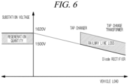
- FIG. 6 is a diagram for explaining a control operation in the DC railway transformation system 10 according to the present disclosure.
- the controller 500 controls the electronic tap changer 200 such that the voltage is set to a rated voltage at a current under a full load or less based on the output voltage and output current of the rectifier 300 measured by the meter 400 and the voltage is dropped in proportion to an internal resistance R of the transformer under the full load or more.
- the whole operation may be classified into an operation when the electric vehicle runs and an operation when the electric vehicle stops.
- a rated voltage of a substation is set to 110% of a voltage of the vehicle. If a load increases when the electric vehicle runs, the tap changer 200 is operated to increase a secondary voltage of the transformer (decrease the primary winding wire) and thus increase an input voltage of the electric vehicle and improve the efficiency of the electric vehicle. Therefore, even when the electric vehicle is far away from the substation, the tap changer 200 can decrease a current flowing through a railway line and significantly decrease heat loss.
- a motor of the electric vehicle when the electric vehicle stops, a motor of the electric vehicle generates electric energy and a secondary voltage is lowered to 100% or less of the voltage by a tap change (increasing the primary winding wire), and, thus, a starting voltage for electricity generation of the electric vehicle is lowered. Therefore, the power generation amount in a regeneration mode can be increased and the power production amount can be increased.
- electricity generation starts at 110% of a substation voltage when no load is applied.
- the voltage reaches 120% electricity generated by the electric vehicle is not transmitted to the substation for the safety of the substation but dissipates through heat generation across an internal resistance of the electric vehicle.
- the voltage generated in the regeneration mode can be actively utilized.
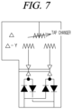
- FIG. 7 illustrates a configuration of a switchable transformer according to an embodiment of the present disclosure.
- the switchable transformer 100 consists of three winding wires including ⁇ wiring on a primary side and ⁇ wiring and Y wiring on a secondary side.
- the Y wiring can be placed on the primary side.
- the tap changer is connected to the wiring on the primary side and a winding wire ratio on the primary side is regulated to regulate a voltage ratio on the secondary side. That is, taps are provided in the middle of the winding wire on the primary side and are connected to each other by an electronic switch to increase or decrease the voltage.
- the two winding wires on the secondary side may be connected to respective rectifiers to form a 16-pulse rectifier.
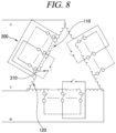
- FIG. 8 is a diagram for explaining a transformer switching operation using a tap changer according to an embodiment of the present disclosure.
- FIG. 8 illustrates a configuration in which the electronic tap changer 200 is connected to the primary side of the switchable transformer 100 in the form of a 3-phase transformer including ⁇ wiring.
- the switchable transformer 100 includes three primary winding wires constituting the ⁇ wiring, and each primary winding wire includes a switchable winding wire 110 and an auxiliary winding wire 120.
- the switchable winding wire 110 and the auxiliary winding wire 120 are separated from each other, but may be connected to each other by the electronic tap changer 200.
- the electronic tap changer 200 includes a plurality of taps connected to different locations of the switchable winding wire 110 as the primary winding wire and a plurality of switching elements connected to the plurality of taps, respectively. One terminals of the plurality of switching elements are connected to the auxiliary winding wire 120 and the other terminals of the switching elements are connected to the taps. When any one of the plurality of switching elements is turned on, a tap connected to the switching element is connected to the auxiliary winding wire 120.
- the electronic tap changer 200 uses a switching element which is turned on by an electric signal, and, thus, the primary winding wire increases or decreases, which results in an increase or decrease in the secondary voltage.
- the secondary voltage when a tap change is performed to increase the primary winding wire, the secondary voltage is decreased, and when a tap change is performed to decrease the primary winding wire, the secondary voltage is increased.
- a rated voltage is output as a reference voltage.
- the electronic tap changer 200 is switched to a center tap to supply the rated voltage.
- the auxiliary winding wire 120 is switched to an adjacent tap to decrease the primary winding wire and thus to increase the secondary voltage in consideration of a voltage drop.
- the electronic tap changer 200 may be further connected to a mechanical breaker 210. This is to suppress a breakdown of the electronic tap changer 200.
- the mechanical breaker 210 is configured to connect a center tap of the switchable winding wire 110 to the auxiliary winding wire 120, and maintains a turn-off state in a normal state.
- the mechanical breaker 210 is operated to connect the center tap of the switchable winding wire 110 to the auxiliary winding wire 120.
- the primary winding wire supplies the rated voltage.
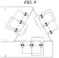
- FIG. 9 illustrates the electronic tap changer 200 according to an embodiment of the present disclosure.
- the electronic tap changer 200 shown in FIG. 9 has a similar structure to the tap changer shown in FIG. 8 , and the switching elements included in the electronic tap changer 200 are implemented with thyristors.
- FIG. 10 and FIG. 11 are flowcharts showing a method of operating the DC railway transformation system according to an embodiment of the present disclosure.
- the DC railway transformation system 10 measures an output voltage or output current of the rectifier 300 which rectifies an output voltage of the 3-phase switchable transformer 100 (S1010).
- the output voltage of the 3-phase switchable transformer 100 is regulated by controlling an operation of the DC railway tap changer 200 based on the output voltage or output current measured by the meter 400 (S1020).
- the tap changer 200 when the output voltage of the rectifier 300 measured by the meter 400 is lower than a first threshold voltage (for example, 1500 V), the tap changer 200 is operated to decrease the primary winding wire and thus to increase the voltage supplied to the DC railway (the secondary voltage of the transformer). Therefore, the secondary voltage is increased. In this case, if a load current is positive when the load current is compared to the threshold value, the tap changer 200 can be operated.
- a first threshold voltage for example, 1500 V
- the tap changer 200 is operated to decrease the voltage supplied to the DC railway (the secondary voltage of the transformer) and thus to increase the primary winding wire. Therefore, the secondary voltage is decreased.
- the second threshold value for example, 1620 V
- the embodiment of the present disclosure can be embodied in a storage medium including instruction codes executable by a computer such as a program module executed by the computer.
- a computer-readable medium can be any usable medium which can be accessed by the computer and includes all volatile/non-volatile and removable/non-removable media. Further, the computer-readable medium may include all computer storage media.
- the computer storage media include all volatile/non-volatile and removable/non-removable media embodied by a certain method or technology for storing information such as computer-readable instruction code, a data structure, a program module or other data.
Landscapes
- Engineering & Computer Science (AREA)
- Power Engineering (AREA)
- Rectifiers (AREA)
- Electric Propulsion And Braking For Vehicles (AREA)
Abstract
A DC railway transformation system according to an embodiment of the present disclosure includes a 3-phase switchable transformer of which a plurality of taps is connected to each primary winding wire; a tap changer which is selectively in contact with the plurality of taps connected to each primary winding wire of the 3-phase switchable transformer and regulates an output voltage of the switchable transformer; a rectifier which rectifies the output voltage of the 3-phase switchable transformer; a meter which measures an output voltage or output current of the rectifier; and a controller which outputs a control signal to control an operation of the tap changer based on the output voltage or output current measured by the meter.
Description
- The present disclosure relates to a DC railway transformation system and a method of operating the same.
-
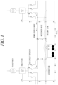
FIG. 1 illustrates a conventional DC railway power supply system. - As for a DC railway, 3-phase power is supplied from an electric power company and the voltage is lowered by using a rectifier transformer, and DC power is generated by using a diode rectifier and supplied to a DC electric vehicle through a railway line.
-
FIG. 2 illustrates a configuration of a rectifying circuit in the conventional DC railway power supply system. - The rectifier transformer can be classified into a 6-pulse rectifying circuit (
FIG. 2(a) ) that converts a 3-phase into a 3-phase, a 12-pulse rectifying circuit (FIG. 2(b) ) that converts a 3-phase into two 3-phases, and a 24-pulse rectifying circuit (FIG. 2(c) ) that converts a 3-phase into four 3-phases. Each number of pulses means the number of times of rectification by a diode rectifier. As the number of pulses increases, the distortion of a rectifier input current decreases. - The most commonly used 12-pulse rectifying circuit is configured by using a rectifier transformer that converts 3-phase power received from an electric power company into Y or Δ-Y/Δ and six rectifying circuits having a phase difference of 30° with two winding wires Y and Δ on an output side. The 24-pulse rectifying circuit uses two rectifier transformers Δ-Y/Δ and Y-Y/Δ in parallel, which results in a phase difference of 15°.
-
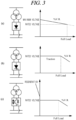
FIG. 3 illustrates an improved configuration of the rectifying circuit in the conventional DC railway power supply system. - In general, a diode is used for rectification. However, as shown in
FIG. 3(a) , an increase in a load on a DC electric vehicle results in a drop in a rectifier output voltage caused by an internal resistance of a transformer. Therefore, the voltage for no load can be set to 110% of a rated voltage. To suppress a voltage drop caused by a load, a thyristor rectifier as shown inFIG. 3(b) may be used to output a constant voltage. Alternatively, a double-way rectifier using an IGBT as shown inFIG. 3(c) may be used to use regenerative power generated when the DC electric vehicle stops and to transmit DC power to the AC side. However, the thyristor rectifier and the IGBT double-way rectifier are expensive. Therefore, they have been used only in particular situations of electric railways. - The present disclosure suggests a DC railway transformation system using an electronic tap changer, which can replace the conventional thyristor rectifier or IGBT rectifier, in a DC railway system.
-
Korean Patent No. 10-2158490 - In view of the foregoing, the present disclosure is conceived to provide a DC railway transformation system configured to control an operation of an electronic tap changer that measures an output voltage and current of a rectifier and regulates winding wires of a switchable transformer based on the result of the measurement.
- The problems to be solved by the present disclosure are not limited to the above-described problems. There may be other problems to be solved by the present disclosure.
- An aspect of the present disclosure provides a DC railway transformation system, including: a 3-phase switchable transformer of which a plurality of taps is connected to each primary winding wire; a tap changer which is selectively in contact with the plurality of taps connected to each primary winding wire of the 3-phase switchable transformer and regulates an output voltage of the switchable transformer; a rectifier which rectifies the output voltage of the 3-phase switchable transformer; a meter which measures an output voltage or output current of the rectifier; and a controller which outputs a control signal to control an operation of the tap changer based on the output voltage or output current measured by the meter. Herein, the controller controls the tap changer to increase the output voltage of the 3-phase switchable transformer when the measured output voltage is lower than a first threshold value and controls the tap changer to decrease the output voltage of the 3-phase switchable transformer when the measured output voltage is equal to or higher than a second threshold value.
- Another aspect of the present disclosure provides a method of operating a DC railway transformation system, including: measuring an output voltage or output current of a rectifier which rectifies an output voltage of a 3-phase switchable transformer; and regulating the output voltage of the 3-phase switchable transformer by controlling an operation of a DC railway tap changer based on the output voltage or output current measured by a meter, and the regulating process is performed to increase the output voltage of the 3-phase switchable transformer by controlling the tap changer when the measured output voltage is lower than a first threshold value and performed to decrease the output voltage of the 3-phase switchable transformer by controlling the tap changer when the measured output voltage is equal to or higher than a second threshold value.
- According to the present disclosure, it is possible to minimize a drop voltage under a full load or more even without using a thyristor rectifier or an IGBT double-way rectifier placed at an output terminal of a transformer.
- According to the conventional technology, a tap changer is connected to a secondary winding wire, whereas according to the present disclosure, a secondary voltage is regulated by regulating a primary winding wire, which can bring economic effects.
-
-
FIG. 1 illustrates a conventional DC railway power supply system. -
FIG. 2 illustrates a configuration of a rectifying circuit in the conventional DC railway power supply system. -
FIG. 3 illustrates an improved configuration of the rectifying circuit in the conventional DC railway power supply system. -
FIG. 4 andFIG. 5 illustrate a DC railway transformation system according to an embodiment of the present disclosure. -
FIG. 6 is a diagram for explaining a control operation in the DC railway transformation system according to the present disclosure. -
FIG. 7 illustrates a configuration of a switchable transformer according to an embodiment of the present disclosure. -
FIG. 8 is a diagram for explaining a transformer switching operation using a tap changer according to an embodiment of the present disclosure. -
FIG. 9 illustrates an electronic tap changer according to an embodiment of the present disclosure. -
FIG. 10 andFIG. 11 are flowcharts showing a method of operating the DC railway transformation system according to an embodiment of the present disclosure. - Hereafter, embodiments will be described in detail with reference to the accompanying drawings so that the present disclosure may be readily implemented by a person with ordinary skill in the art. However, it is to be noted that the present disclosure is not limited to the embodiments but can be embodied in various other ways. In the drawings, parts irrelevant to the description are omitted for the simplicity of explanation, and like reference numerals denote like parts through the whole document.
- Throughout this document, the term "connected to" may be used to designate a connection or coupling of one element to another element and includes both an element being "directly connected to" another element and an element being "electronically connected to" another element via another element.
- Through the whole document, the term "on" that is used to designate a position of one element with respect to another element includes both a case that the one element is adjacent to the other element and a case that any other element exists between these two elements.
- Further, through the whole document, the term "comprises or includes" and/or "comprising or including" used in the document means that one or more other components, steps, operation and/or existence or addition of elements are not excluded in addition to the described components, steps, operation and/or elements unless context dictates otherwise. Through the whole document, the term "about or approximately" or "substantially" is intended to have meanings close to numerical values or ranges specified with an allowable error and intended to prevent accurate or absolute numerical values disclosed for understanding of the present disclosure from being illegally or unfairly used by any unconscionable third party. Through the whole document, the term "step of" does not mean "step for".
- Through the whole document, the term "unit" includes a unit implemented by hardware or software and a unit implemented by both of them. One unit may be implemented by two or more pieces of hardware, and two or more units may be implemented by one piece of hardware. Meanwhile, the units are not limited to the software or the hardware, and each of the units may be stored in an addressable storage medium or may be configured to implement one or more processors. Accordingly, the units may include, for example, software, object-oriented software, classes, tasks, processes, functions, attributes, procedures, sub-routines, segments of program codes, drivers, firmware, micro codes, circuits, data, database, data structures, tables, arrays, variables and the like. The components and the functions of the units can be combined with each other or can be divided up into additional components and units.
- Hereafter, exemplary embodiments of the present disclosure will be described in detail with reference to the accompanying drawings and description. However, the present disclosure is not limited to the following embodiments and can be embodied in a different form. Like reference numerals generally denote like elements throughout the present specification.
-
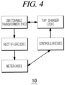
FIG. 4 andFIG. 5 illustrate a DC railway transformation system according to an embodiment of the present disclosure. - The present disclosure suggests a DC
railway transformation system 10 using an electronic tap changer, which can replace the conventional thyristor rectifier or IGBT rectifier, in a DC railway system. According to the present disclosure, it is possible to control an operation of the electronic tap changer that measures an output voltage and current of a rectifier and regulates winding wires of a switchable transformer based on the result of the measurement. - That is, the electronic tap changer is controlled such that the voltage is set to a rated voltage at a current under a full load or less based on the result of the measurement of the output voltage and current of the rectifier and the voltage is dropped in proportion to an internal resistance R of the transformer under the full load or more.
- Referring to
FIG. 4 , the DCrailway transformation system 10 of the present disclosure includes aswitchable transformer 100, atap changer 200, arectifier 300, ameter 400, and acontroller 500. - The
switchable transformer 100 is a 3-phase switchable transformer of which a plurality of taps is connected to each primary winding wire. - The
tap changer 200 is selectively in contact with the plurality of taps connected to each primary winding wire of the 3-phase switchable transformer and regulates an output voltage of theswitchable transformer 100. - The
rectifier 300 rectifies the output voltage of theswitchable transformer 100. - The
meter 400 measures an output voltage or output current of therectifier 300. - The
controller 500 outputs a control signal to control an operation of thetap changer 200 based on the output voltage or output current measured by themeter 400. Thecontroller 500 controls thetap changer 200 to increase the output voltage of the 3-phaseswitchable transformer 100 when the measured output voltage is lower than a first threshold value and controls thetap changer 200 to decrease the output voltage of the 3-phaseswitchable transformer 100 when the measured output voltage is equal to or higher than a second threshold value. In this case, the first threshold value is set to be lower than the second threshold value. -
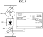
FIG. 5 illustrates the DCrailway transformation system 10 of the present disclosure in more detail, andFIG. 6 is a diagram for explaining a control operation in the DCrailway transformation system 10 according to the present disclosure. - Referring to
FIG. 5 , thecontroller 500 controls theelectronic tap changer 200 such that the voltage is set to a rated voltage at a current under a full load or less based on the output voltage and output current of therectifier 300 measured by themeter 400 and the voltage is dropped in proportion to an internal resistance R of the transformer under the full load or more. - Changes in load according to the present disclosure will be described below with reference to
FIG. 6 . - The whole operation may be classified into an operation when the electric vehicle runs and an operation when the electric vehicle stops.
- If no load is applied when the electric vehicle runs, a rated voltage of a substation is set to 110% of a voltage of the vehicle. If a load increases when the electric vehicle runs, the
tap changer 200 is operated to increase a secondary voltage of the transformer (decrease the primary winding wire) and thus increase an input voltage of the electric vehicle and improve the efficiency of the electric vehicle. Therefore, even when the electric vehicle is far away from the substation, thetap changer 200 can decrease a current flowing through a railway line and significantly decrease heat loss. - Also, when the electric vehicle stops, a motor of the electric vehicle generates electric energy and a secondary voltage is lowered to 100% or less of the voltage by a tap change (increasing the primary winding wire), and, thus, a starting voltage for electricity generation of the electric vehicle is lowered. Therefore, the power generation amount in a regeneration mode can be increased and the power production amount can be increased.
- In a conventional case, electricity generation starts at 110% of a substation voltage when no load is applied. When the voltage reaches 120%, electricity generated by the electric vehicle is not transmitted to the substation for the safety of the substation but dissipates through heat generation across an internal resistance of the electric vehicle. Thus, as in the present disclosure, the voltage generated in the regeneration mode can be actively utilized.
-
FIG. 7 illustrates a configuration of a switchable transformer according to an embodiment of the present disclosure. - Referring to
FIG. 7 , theswitchable transformer 100 consists of three winding wires including Δ wiring on a primary side and Δ wiring and Y wiring on a secondary side. However, the Y wiring can be placed on the primary side. In the present disclosure, the tap changer is connected to the wiring on the primary side and a winding wire ratio on the primary side is regulated to regulate a voltage ratio on the secondary side. That is, taps are provided in the middle of the winding wire on the primary side and are connected to each other by an electronic switch to increase or decrease the voltage. - For reference, the two winding wires on the secondary side may be connected to respective rectifiers to form a 16-pulse rectifier.
-
FIG. 8 is a diagram for explaining a transformer switching operation using a tap changer according to an embodiment of the present disclosure. -
FIG. 8 illustrates a configuration in which theelectronic tap changer 200 is connected to the primary side of theswitchable transformer 100 in the form of a 3-phase transformer including Δ wiring. - The
switchable transformer 100 includes three primary winding wires constituting the Δ wiring, and each primary winding wire includes a switchable windingwire 110 and an auxiliary windingwire 120. Theswitchable winding wire 110 and the auxiliary windingwire 120 are separated from each other, but may be connected to each other by theelectronic tap changer 200. - The
electronic tap changer 200 includes a plurality of taps connected to different locations of theswitchable winding wire 110 as the primary winding wire and a plurality of switching elements connected to the plurality of taps, respectively. One terminals of the plurality of switching elements are connected to the auxiliary windingwire 120 and the other terminals of the switching elements are connected to the taps. When any one of the plurality of switching elements is turned on, a tap connected to the switching element is connected to the auxiliary windingwire 120. Theelectronic tap changer 200 uses a switching element which is turned on by an electric signal, and, thus, the primary winding wire increases or decreases, which results in an increase or decrease in the secondary voltage. - That is, according to the configuration of the transformer, when a tap change is performed to increase the primary winding wire, the secondary voltage is decreased, and when a tap change is performed to decrease the primary winding wire, the secondary voltage is increased.
- When a tap located in the middle of a winding wire among the plurality of taps is selected, a rated voltage is output as a reference voltage.
- Hereafter, a detailed operation of the
controller 500 will be described. Under a full load or less, theelectronic tap changer 200 is switched to a center tap to supply the rated voltage. Under a full load or more, the auxiliary windingwire 120 is switched to an adjacent tap to decrease the primary winding wire and thus to increase the secondary voltage in consideration of a voltage drop. - The
electronic tap changer 200 may be further connected to amechanical breaker 210. This is to suppress a breakdown of theelectronic tap changer 200. Themechanical breaker 210 is configured to connect a center tap of theswitchable winding wire 110 to the auxiliary windingwire 120, and maintains a turn-off state in a normal state. When theelectronic tap changer 200 breaks down, themechanical breaker 210 is operated to connect the center tap of theswitchable winding wire 110 to the auxiliary windingwire 120. Thus, the primary winding wire supplies the rated voltage. -
FIG. 9 illustrates theelectronic tap changer 200 according to an embodiment of the present disclosure. Theelectronic tap changer 200 shown inFIG. 9 has a similar structure to the tap changer shown inFIG. 8 , and the switching elements included in theelectronic tap changer 200 are implemented with thyristors. -
FIG. 10 andFIG. 11 are flowcharts showing a method of operating the DC railway transformation system according to an embodiment of the present disclosure. - Referring to
FIG. 10 , the DCrailway transformation system 10 measures an output voltage or output current of therectifier 300 which rectifies an output voltage of the 3-phase switchable transformer 100 (S1010). - The output voltage of the 3-phase
switchable transformer 100 is regulated by controlling an operation of the DCrailway tap changer 200 based on the output voltage or output current measured by the meter 400 (S1020). - As shown in
FIG. 11 , when the output voltage of therectifier 300 measured by themeter 400 is lower than a first threshold voltage (for example, 1500 V), thetap changer 200 is operated to decrease the primary winding wire and thus to increase the voltage supplied to the DC railway (the secondary voltage of the transformer). Therefore, the secondary voltage is increased. In this case, if a load current is positive when the load current is compared to the threshold value, thetap changer 200 can be operated. - Also, if the measured voltage is equal to or higher than the second threshold value (for example, 1620 V), the
tap changer 200 is operated to decrease the voltage supplied to the DC railway (the secondary voltage of the transformer) and thus to increase the primary winding wire. Therefore, the secondary voltage is decreased. - The embodiment of the present disclosure can be embodied in a storage medium including instruction codes executable by a computer such as a program module executed by the computer. A computer-readable medium can be any usable medium which can be accessed by the computer and includes all volatile/non-volatile and removable/non-removable media. Further, the computer-readable medium may include all computer storage media. The computer storage media include all volatile/non-volatile and removable/non-removable media embodied by a certain method or technology for storing information such as computer-readable instruction code, a data structure, a program module or other data.
- The method and system of the present disclosure have been explained in relation to a specific embodiment, but their components or a part or all of their operations can be embodied by using a computer system having general-purpose hardware architecture.
- The above description of the present disclosure is provided for the purpose of illustration, and it would be understood by a person with ordinary skill in the art that various changes and modifications may be made without changing technical conception and essential features of the present disclosure. Thus, it is clear that the above-described examples are illustrative in all aspects and do not limit the present disclosure. For example, each component described to be of a single type can be implemented in a distributed manner. Likewise, components described to be distributed can be implemented in a combined manner.
- The scope of the present disclosure is defined by the following claims rather than by the detailed description of the embodiment. It shall be understood that all modifications and embodiments conceived from the meaning and scope of the claims and their equivalents are included in the scope of the present disclosure.
Claims (7)
- A DC railway transformation system, comprising:a 3-phase switchable transformer of which a plurality of taps is connected to each primary winding wire;a tap changer which is selectively in contact with the plurality of taps connected to each primary winding wire of the 3-phase switchable transformer and regulates an output voltage of the switchable transformer;a rectifier which rectifies the output voltage of the 3-phase switchable transformer;a meter which measures an output voltage or output current of the rectifier; anda controller which outputs a control signal to control an operation of the tap changer based on the output voltage or output current measured by the meter,wherein the controller controls the tap changer to increase the output voltage of the 3-phase switchable transformer when the measured output voltage is lower than a first threshold value and controls the tap changer to decrease the output voltage of the 3-phase switchable transformer when the measured output voltage is equal to or higher than a second threshold value.
- The DC railway transformation system of Claim 1,
wherein the controller controls the tap changer to decrease the number of the primary winding wires when the measured output voltage is lower than the first threshold value and controls the tap changer to increase the number of the primary winding wires when the measured output voltage is equal to or higher than the second threshold value. - The DC railway transformation system of Claim 1,wherein the switchable transformer includes three primary winding wires constituting Δ wiring, and each primary winding wire includes a switchable winding wire and an auxiliary winding wire,the tap changer includes a plurality of taps connected to different locations of the switchable winding wire and a plurality of switching elements which connects one terminals of the auxiliary winding wires to the plurality of taps, respectively, andwhen any one of the plurality of switching elements is turned on, a tap connected to the switching element is selectively connected to the auxiliary winding wire.
- The DC railway transformation system of Claim 3, further comprising:
a mechanical breaker configured to connect a center tap of the switchable winding wire to the auxiliary winding wire. - The DC railway transformation system of Claim 3,
wherein the plurality of switching elements are thyristors. - A method of operating a DC railway transformation system, comprising:measuring an output voltage or output current of a rectifier which rectifies an output voltage of a 3-phase switchable transformer; andregulating the output voltage of the 3-phase switchable transformer by controlling an operation of a DC railway tap changer based on the output voltage or output current measured by a meter,wherein the regulating process is performed to increase the output voltage of the 3-phase switchable transformer by controlling the tap changer when the measured output voltage is lower than a first threshold value and performed to decrease the output voltage of the 3-phase switchable transformer by controlling the tap changer when the measured output voltage is equal to or higher than a second threshold value.
- The method of operating a DC railway transformation system of Claim 6,
wherein the regulating process is performed to decrease the number of the primary winding wires by controlling the tap changer when the measured output voltage is lower than the first threshold value and performed to increase the output voltage of the number of the primary winding wires by controlling the tap changer when the measured output voltage is equal to or higher than the second threshold value.
Applications Claiming Priority (1)
| Application Number | Priority Date | Filing Date | Title |
|---|---|---|---|
| KR1020230080839A KR102845906B1 (en) | 2023-06-23 | 2023-06-23 | Transformation system for direct current railway and its operation method |
Publications (1)
| Publication Number | Publication Date |
|---|---|
| EP4482021A1 true EP4482021A1 (en) | 2024-12-25 |
Family
ID=88837372
Family Applications (1)
| Application Number | Title | Priority Date | Filing Date |
|---|---|---|---|
| EP23210383.8A Pending EP4482021A1 (en) | 2023-06-23 | 2023-11-16 | Dc railway transformation system and method of operating the same |
Country Status (2)
| Country | Link |
|---|---|
| EP (1) | EP4482021A1 (en) |
| KR (1) | KR102845906B1 (en) |
Citations (3)
| Publication number | Priority date | Publication date | Assignee | Title |
|---|---|---|---|---|
| US3700925A (en) * | 1971-03-29 | 1972-10-24 | Westinghouse Electric Corp | Thyristor tap changer for electrical inductive apparatus |
| KR100629429B1 (en) * | 2004-12-24 | 2006-09-27 | 한국철도기술연구원 | Railway system and method for maintaining feeder voltage of wire |
| KR102158490B1 (en) | 2018-08-08 | 2020-09-23 | 한국철도기술연구원 | Device for controlling vehicle collection voltage of dc electric railway |
Family Cites Families (2)
| Publication number | Priority date | Publication date | Assignee | Title |
|---|---|---|---|---|
| KR200359478Y1 (en) * | 2004-05-28 | 2004-08-21 | 캐리어엘지 유한회사 | Apparatus for compensating ac power |
| EP3839993A1 (en) * | 2019-12-17 | 2021-06-23 | ABB Power Grids Switzerland AG | Power electronics on-load tap changer with a reduced number of taps |
-
2023
- 2023-06-23 KR KR1020230080839A patent/KR102845906B1/en active Active
- 2023-11-16 EP EP23210383.8A patent/EP4482021A1/en active Pending
Patent Citations (3)
| Publication number | Priority date | Publication date | Assignee | Title |
|---|---|---|---|---|
| US3700925A (en) * | 1971-03-29 | 1972-10-24 | Westinghouse Electric Corp | Thyristor tap changer for electrical inductive apparatus |
| KR100629429B1 (en) * | 2004-12-24 | 2006-09-27 | 한국철도기술연구원 | Railway system and method for maintaining feeder voltage of wire |
| KR102158490B1 (en) | 2018-08-08 | 2020-09-23 | 한국철도기술연구원 | Device for controlling vehicle collection voltage of dc electric railway |
Non-Patent Citations (1)
| Title |
|---|
| CANALES JOSE MARIA ET AL: "Electronic on Load Tap Changer Transformer for DC Electrical Railway Power Supply Systems", 2019 IEEE VEHICLE POWER AND PROPULSION CONFERENCE (VPPC), IEEE, 14 October 2019 (2019-10-14), pages 1 - 4, XP033687933, DOI: 10.1109/VPPC46532.2019.8952415 * |
Also Published As
| Publication number | Publication date |
|---|---|
| KR102845906B1 (en) | 2025-08-18 |
| KR20240178744A (en) | 2024-12-31 |
Similar Documents
| Publication | Publication Date | Title |
|---|---|---|
| US7170767B2 (en) | System and method for regenerative PWM AC power conversion | |
| US7009853B2 (en) | Switched-mode power supply arrangement | |
| EP2067229B1 (en) | Conversion of ac lines to hvdc lines | |
| JP2012010542A (en) | Serial multiple inverter device and control method thereof | |
| CN118100260B (en) | Flexible alternating current interconnection device and control method | |
| CN102647097A (en) | Power supply device | |
| KR20210150852A (en) | Hybrid semiconductor transformer | |
| US20230104735A1 (en) | Fuel Cell Power System | |
| US11349382B2 (en) | Controller | |
| US12149066B2 (en) | DC power distribution system | |
| JPH0254012B2 (en) | ||
| EP4482021A1 (en) | Dc railway transformation system and method of operating the same | |
| US20230034870A1 (en) | Static transfer switch, and ups module to which static transfer switch is applied | |
| US5793622A (en) | Common turn-off circuit for a thyristor power converter | |
| KR102158490B1 (en) | Device for controlling vehicle collection voltage of dc electric railway | |
| US6016262A (en) | Converter equipment | |
| JP7641856B2 (en) | Charging equipment | |
| KR20230081786A (en) | Integrated inverter for small electric vehicle with the neutral point of the charing motor removed | |
| CN116260146A (en) | A high-voltage direct current converter station active voltage regulation topology and system | |
| JP2680385B2 (en) | Auxiliary power supply for electric vehicles | |
| CN119765977B (en) | Enhanced bidirectional converter with built-in rectifier and control method thereof | |
| KR102557486B1 (en) | Integrated inverter for small electric motor driving device | |
| JPH0556643A (en) | Rectifier device | |
| JPH11162491A (en) | Output converter for fuel cells | |
| Kumar | Intelligent Universal Transformer |
Legal Events
| Date | Code | Title | Description |
|---|---|---|---|
| PUAI | Public reference made under article 153(3) epc to a published international application that has entered the european phase |
Free format text: ORIGINAL CODE: 0009012 |
|
| STAA | Information on the status of an ep patent application or granted ep patent |
Free format text: STATUS: REQUEST FOR EXAMINATION WAS MADE |
|
| 17P | Request for examination filed |
Effective date: 20231117 |
|
| AK | Designated contracting states |
Kind code of ref document: A1 Designated state(s): AL AT BE BG CH CY CZ DE DK EE ES FI FR GB GR HR HU IE IS IT LI LT LU LV MC ME MK MT NL NO PL PT RO RS SE SI SK SM TR |