EP4481933A1 - Electrode assembly having curved tab bundle, and electrode assembly tab bundle forming device for manufacturing same - Google Patents
Electrode assembly having curved tab bundle, and electrode assembly tab bundle forming device for manufacturing same Download PDFInfo
- Publication number
- EP4481933A1 EP4481933A1 EP23891928.6A EP23891928A EP4481933A1 EP 4481933 A1 EP4481933 A1 EP 4481933A1 EP 23891928 A EP23891928 A EP 23891928A EP 4481933 A1 EP4481933 A1 EP 4481933A1
- Authority
- EP
- European Patent Office
- Prior art keywords
- tab bundle
- die
- electrode assembly
- tab
- electrode
- Prior art date
- Legal status (The legal status is an assumption and is not a legal conclusion. Google has not performed a legal analysis and makes no representation as to the accuracy of the status listed.)
- Pending
Links
Images



Classifications
-
- H—ELECTRICITY
- H01—ELECTRIC ELEMENTS
- H01M—PROCESSES OR MEANS, e.g. BATTERIES, FOR THE DIRECT CONVERSION OF CHEMICAL ENERGY INTO ELECTRICAL ENERGY
- H01M50/00—Constructional details or processes of manufacture of the non-active parts of electrochemical cells other than fuel cells, e.g. hybrid cells
- H01M50/50—Current conducting connections for cells or batteries
- H01M50/531—Electrode connections inside a battery casing
- H01M50/54—Connection of several leads or tabs of plate-like electrode stacks, e.g. electrode pole straps or bridges
-
- B—PERFORMING OPERATIONS; TRANSPORTING
- B21—MECHANICAL METAL-WORKING WITHOUT ESSENTIALLY REMOVING MATERIAL; PUNCHING METAL
- B21D—WORKING OR PROCESSING OF SHEET METAL OR METAL TUBES, RODS OR PROFILES WITHOUT ESSENTIALLY REMOVING MATERIAL; PUNCHING METAL
- B21D13/00—Corrugating sheet metal, rods or profiles; Bending sheet metal, rods or profiles into wave form
- B21D13/02—Corrugating sheet metal, rods or profiles; Bending sheet metal, rods or profiles into wave form by pressing
-
- B—PERFORMING OPERATIONS; TRANSPORTING
- B21—MECHANICAL METAL-WORKING WITHOUT ESSENTIALLY REMOVING MATERIAL; PUNCHING METAL
- B21D—WORKING OR PROCESSING OF SHEET METAL OR METAL TUBES, RODS OR PROFILES WITHOUT ESSENTIALLY REMOVING MATERIAL; PUNCHING METAL
- B21D35/00—Combined processes according to or processes combined with methods covered by groups B21D1/00 - B21D31/00
- B21D35/002—Processes combined with methods covered by groups B21D1/00 - B21D31/00
- B21D35/005—Processes combined with methods covered by groups B21D1/00 - B21D31/00 characterized by the material of the blank or the workpiece
- B21D35/007—Layered blanks
-
- B—PERFORMING OPERATIONS; TRANSPORTING
- B21—MECHANICAL METAL-WORKING WITHOUT ESSENTIALLY REMOVING MATERIAL; PUNCHING METAL
- B21D—WORKING OR PROCESSING OF SHEET METAL OR METAL TUBES, RODS OR PROFILES WITHOUT ESSENTIALLY REMOVING MATERIAL; PUNCHING METAL
- B21D39/00—Application of procedures in order to connect objects or parts, e.g. coating with sheet metal otherwise than by plating; Tube expanders
- B21D39/02—Application of procedures in order to connect objects or parts, e.g. coating with sheet metal otherwise than by plating; Tube expanders of sheet metal by folding, e.g. connecting edges of a sheet to form a cylinder
- B21D39/026—Reinforcing the connection by locally deforming
-
- B—PERFORMING OPERATIONS; TRANSPORTING
- B21—MECHANICAL METAL-WORKING WITHOUT ESSENTIALLY REMOVING MATERIAL; PUNCHING METAL
- B21D—WORKING OR PROCESSING OF SHEET METAL OR METAL TUBES, RODS OR PROFILES WITHOUT ESSENTIALLY REMOVING MATERIAL; PUNCHING METAL
- B21D5/00—Bending sheet metal along straight lines, e.g. to form simple curves
- B21D5/01—Bending sheet metal along straight lines, e.g. to form simple curves between rams and anvils or abutments
-
- H—ELECTRICITY
- H01—ELECTRIC ELEMENTS
- H01M—PROCESSES OR MEANS, e.g. BATTERIES, FOR THE DIRECT CONVERSION OF CHEMICAL ENERGY INTO ELECTRICAL ENERGY
- H01M10/00—Secondary cells; Manufacture thereof
- H01M10/04—Construction or manufacture in general
-
- H—ELECTRICITY
- H01—ELECTRIC ELEMENTS
- H01M—PROCESSES OR MEANS, e.g. BATTERIES, FOR THE DIRECT CONVERSION OF CHEMICAL ENERGY INTO ELECTRICAL ENERGY
- H01M10/00—Secondary cells; Manufacture thereof
- H01M10/04—Construction or manufacture in general
- H01M10/0404—Machines for assembling batteries
-
- H—ELECTRICITY
- H01—ELECTRIC ELEMENTS
- H01M—PROCESSES OR MEANS, e.g. BATTERIES, FOR THE DIRECT CONVERSION OF CHEMICAL ENERGY INTO ELECTRICAL ENERGY
- H01M10/00—Secondary cells; Manufacture thereof
- H01M10/05—Accumulators with non-aqueous electrolyte
- H01M10/058—Construction or manufacture
- H01M10/0585—Construction or manufacture of accumulators having only flat construction elements, i.e. flat positive electrodes, flat negative electrodes and flat separators
-
- H—ELECTRICITY
- H01—ELECTRIC ELEMENTS
- H01M—PROCESSES OR MEANS, e.g. BATTERIES, FOR THE DIRECT CONVERSION OF CHEMICAL ENERGY INTO ELECTRICAL ENERGY
- H01M50/00—Constructional details or processes of manufacture of the non-active parts of electrochemical cells other than fuel cells, e.g. hybrid cells
- H01M50/50—Current conducting connections for cells or batteries
- H01M50/531—Electrode connections inside a battery casing
- H01M50/533—Electrode connections inside a battery casing characterised by the shape of the leads or tabs
-
- H—ELECTRICITY
- H01—ELECTRIC ELEMENTS
- H01M—PROCESSES OR MEANS, e.g. BATTERIES, FOR THE DIRECT CONVERSION OF CHEMICAL ENERGY INTO ELECTRICAL ENERGY
- H01M50/00—Constructional details or processes of manufacture of the non-active parts of electrochemical cells other than fuel cells, e.g. hybrid cells
- H01M50/50—Current conducting connections for cells or batteries
- H01M50/531—Electrode connections inside a battery casing
- H01M50/536—Electrode connections inside a battery casing characterised by the method of fixing the leads to the electrodes, e.g. by welding
-
- Y—GENERAL TAGGING OF NEW TECHNOLOGICAL DEVELOPMENTS; GENERAL TAGGING OF CROSS-SECTIONAL TECHNOLOGIES SPANNING OVER SEVERAL SECTIONS OF THE IPC; TECHNICAL SUBJECTS COVERED BY FORMER USPC CROSS-REFERENCE ART COLLECTIONS [XRACs] AND DIGESTS
- Y02—TECHNOLOGIES OR APPLICATIONS FOR MITIGATION OR ADAPTATION AGAINST CLIMATE CHANGE
- Y02E—REDUCTION OF GREENHOUSE GAS [GHG] EMISSIONS, RELATED TO ENERGY GENERATION, TRANSMISSION OR DISTRIBUTION
- Y02E60/00—Enabling technologies; Technologies with a potential or indirect contribution to GHG emissions mitigation
- Y02E60/10—Energy storage using batteries
Definitions
- the present invention relates to an electrode assembly having a curved tab bundle and an electrode assembly tab bundle forming apparatus for manufacturing the same. More particularly, the present invention relates to an electrode assembly configured to have a structure in which stress applied to electrode tabs extending from the electrode assembly is reduced and an electrode assembly tab bundle forming apparatus for manufacturing the same.
- Lithium secondary batteries may be classified based on the type of a battery case in which an electrode assembly is received.
- the lithium secondary batteries may be classified into a prismatic battery cell including a metal can-shaped battery case, a cylindrical battery cell including a metal can-shaped battery case, and a pouch-shaped battery cell made of a laminate sheet including a resin layer and a metal layer.
- the pouch-shaped battery cell has the advantages of easy shape deformation and high energy density.
- the pouch-shaped battery cell is manufactured by receiving an electrode assembly and an electrolyte solution in a pouch-shaped battery case and sealing the pouch-shaped battery case, wherein electrode tabs protruding from the electrode assembly extend in a straight line without a separate shape to constitute an electrode tab bundle, and pre-welding may be performed in this state.
- FIG. 1 is a front view of a conventional electrode assembly and a forming apparatus for forming the same.
- the electrode assembly is configured such that negative electrodes 100 and positive electrodes 300 are stacked in the state in which separators 200 are interposed therebetween, wherein electrode tabs extending from one-side outer peripheries of the negative electrodes 100 of the electrode assembly are pre-welded in the state in which a tab bundle B is formed, and a right end of the tab bundle B is coupled to an electrode lead 400 by welding.
- the electrode tabs are vulnerable to movement of the electrode assembly or stress applied to the electrode assembly in a longitudinal direction (an X-axis direction), and when the electrode assembly swells during the charging and discharging process, the electrode tabs expand in a thickness direction (a Y-axis direction), whereby the electrode tabs may be broken.
- the tab bundle may be bent using a forming apparatus 50 including a first die 51 and a second die 52.
- the first die 51 may press the tab bundle B under the tab bundle and the second die 52 may press the tab bundle B above the tab bundle to deform the tab bundle B such that the outermost tabs of the tab bundle are rounded.
- safety may be improved for expansion in the thickness direction (the Y-axis direction) due to the length margin of the outermost tabs, but for movement in the longitudinal direction (the X-axis direction), there is no length margin of the inner tabs, whereby there is still a high possibility of breakage due to movement or stress in the longitudinal direction (the X-axis direction).
- Patent Document 1 which relates to an electrode assembly manufacturing method and an electrode assembly manufacturing apparatus, discloses a rod process in which a pair of rods is located at an electrode assembly side at a part at which electrode tabs are welded and the pair of rods is moved in a direction in which the pair of rods faces each other so as to come into tight contact with opposite sides of the electrode tabs in order to prevent dust generated during welding from moving to the electrode assembly before a pre-welding process.
- Patent Document 1 discloses a method and structure capable of preventing excessive tension from being applied to the electrode tabs when welding the electrode tabs using the pair of rods, the electrode tab bending structure disclosed in Patent Document 1 is difficult to secure safety against swelling in the thickness direction.
- Patent Document 2 relates to a secondary battery manufacturing method and a secondary battery manufactured using the same, wherein a horn and an anvil for temporarily joining multiple tabs are configured such that the horn has a protrusion protruding toward the anvil and the anvil has a recess corresponding to the protrusion, whereby each of the multiple tabs has a bent portion.
- An addition process of bending the multiple tabs is omitted, whereby the process is simplified.
- the present invention has been made in view of the above problems, and it is an object of the present invention to provide an electrode assembly configured such that the length margin of a tab bundle constituted by electrode tabs stacked while overlapping each other in a longitudinal direction and a thickness direction is secured, whereby breakage of the electrode tabs is prevented, and an electrode assembly tab bundle forming apparatus for manufacturing the same.
- An electrode assembly according to the present invention to accomplish the above object is configured such that a separator is interposed between a plurality of electrodes each having an electrode tab protruding therefrom and the electrode tabs are stacked to form a tab bundle (B), wherein the tab bundle (B) defines a convex portion and a concave portion are successively formed so as to extend in a longitudinal direction of the electrodes.
- One end of the tab bundle (B) in tight contact with an electrode lead may be a flat portion.
- the flat portion may be pre-welded.
- the convex portion and the concave portion may be formed at the remaining part of the tab bundle excluding the flat portion.
- the convex portion and the concave portion may be successively formed in each of the electrode tabs comprising the tab bundle.
- an apparatus for forming a tab bundle of the electrode assembly including a first die configured to be disposed at a first surface of the tab bundle (B); and a second die configured to be disposed at a second surface of the tab bundle (B), wherein the first die includes at least two guide portions spaced apart from each other by a predetermined distance, and the second die is configured to face a gap defined between the at least two guide portions of the first die.
- An end of each guide portion configured to face the first surface of the tab bundle (B) may be convex.
- An end of the second die facing the second surface of the tab bundle may be convex.
- the at least two guide portions of the first die may be driven independently from one another.
- Lower ends of the at least two guide portions of the first die may be connected to each other so as to have an integral structure.
- a connection portion between the at least two guide portions may have a recess having a shape corresponding to the end of the second die.
- the end of the second die may be convex, and the recess may be concave.
- a method of manufacturing the electrode assembly including a first step of stacking a plurality of electrodes each having an electrode tab protruding therefrom such that a separator is interposed therebetween to form a tab bundle (B) of identical electrodes; a second step of locating a first die at a first surface of the tab bundle (B) and locating a second die at a second surface of the tab bundle (B); and a third step of moving the first die and/or the second die toward the tab bundle (B) to bend the tab bundle (B), wherein the first die includes at least two guide portions spaced apart from each other by a predetermined distance, an end of each of the at least two guide portions facing the first surface being convex, and the second die faces a gap defined between the at least two guide portions of the first die, an end of the second die being convex.
- the method may further include a fourth step of pre-welding an end part of the tab bundle (B).
- the method may further include a fifth step of cutting a tip end of the tab bundle (B).
- the present invention may provide various combinations of the above solving means.
- the present invention has the advantage that a convex portion and a concave portion are successively formed at a tab bundle constituted by stacked electrode tabs extending from a plurality of electrodes, whereby it is possible to secure the length margin not only in a longitudinal direction but also in a thickness direction, and therefore it is possible to prevent breakage of the electrode tabs.
- FIG. 2 is a perspective view of an electrode assembly according to the present invention.
- the electrode assembly according to the present invention is configured such that a negative electrode 100 and a positive electrode 300 are stacked in the state in which a separator 200 is interposed therebetween, wherein the negative electrode 100 and the positive electrode 300 include a negative electrode tab 110 and a positive electrode tab 310 protruding in opposite directions, respectively.
- Negative electrode tabs 110 are stacked to constitute a negative electrode tab bundle B, and positive electrode tabs 310 are stacked to constitute a positive electrode tab bundle B. Since the negative electrode tab bundle B and the positive electrode tab bundle B are identical in construction to each other, a description will be given based on the negative electrode tab bundle B.
- Each of the negative electrode tabs 110 constituting the negative electrode tab bundle B is provided with a convex portion 111 and a concave portion 112 extending in a longitudinal direction of the negative electrode 100 (an X-axis direction), and a flat portion 113 is formed at a tip end of each of the negative electrode tabs.
- each of the negative electrode tabs 110 constituting the negative electrode tab bundle B is bent such that the convex portion 111 and the concave portion 112 are successively formed except for the flat portion 113 at the tip end thereof.
- the flat portion 113 is a part to which an electrode lead, a description of which will follow, is coupled, and is preferably pre-welded.
- FIG. 2 shows one convex portion and one concave portion, this is only an example, and two or more convex portions and two or more concave portions may be provided.
- the electrode assembly according to the present invention is configured in the form in which the length margin of the electrode tab is secured, i.e., the form in which the electrode tab bundle is loosely bent rather than taut, whereby it is possible to minimize the breakage of the electrode tabs even though the electrode assembly moves in the longitudinal direction (the X-axis direction) or swells in a Y-axis direction.
- the negative electrode 100 is manufactured by applying a slurry mixture of a negative electrode active material and a binder to a negative electrode current collector.
- the negative electrode active material for example, there may be used carbon, such as non-graphitizing carbon or graphite-based carbon; a metal composite oxide, such as Li x Fe 2 O 3 (0 ⁇ x ⁇ x1), Li x WO 2 (0 ⁇ x ⁇ 1), Sn x Me 1-x Me' y O z (Me: Mn, Fe, Pb, Ge; Me': Al, B, P, Si, Group 1, 2, and 3 elements of the periodic table, halogen; 0 ⁇ x ⁇ 1; 1 ⁇ y ⁇ 3; 1 ⁇ z ⁇ 8); lithium metal; a lithium alloy; a silicon-based alloy; a tin-based alloy; a metal oxide, such as SnO, SnO 2 , PbO, PbO 2 , Pb 2 O 3 , Pb 3 O 4 , Sb 2 O 3 , Sb 2 O 4 , Sb 2 O 5 , GeO, GeO 2 , Bi 2 O 3 , Bi 2 O 4 , or Bi 2 O 5 ; a metal composite
- the positive electrode 300 is manufactured by applying a slurry mixture of a positive electrode active material and a binder to a positive electrode current collector.
- each of the negative electrode current collector and the positive electrode current collector is constituted by a portion to which the slurry including the active material is applied and an uncoated portion to which no slurry is applied.
- the uncoated portion is cut to form the electrode tabs, more specifically the negative electrode tab 110 and the positive electrode tab 310.
- a thin insulating film having high ionic permeability and mechanical strength is used as the separator 200, which is interposed between the negative electrode 100 and the positive electrode 300.
- the pore diameter of the separator is generally 0.01 um to 10 um, and the thickness of the separator is generally 5 um to 300 um.
- a sheet or nonwoven fabric made of, for example, an olefin-based polymer, which is chemically resistant and hydrophobic, such as polypropylene, fiberglass, or polyethylene, may be used as the separator; however, the present invention is not limited thereto.
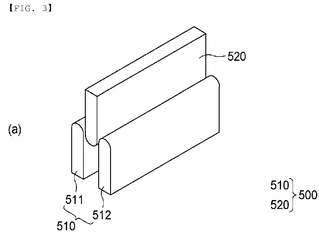
- FIG. 3 is a perspective view of electrode assembly tab bundle forming apparatuses according to a first embodiment and a second embodiment of the present invention, wherein (a) shows a tab bundle forming apparatus according to a first embodiment and (b) shows a tab bundle forming apparatus according to a second embodiment.
- the electrode assembly tab bundle forming apparatus 500 includes a first die 510 located at a first surface of a tab bundle, i.e., a lower surface of the tab bundle B in FIG. 2 , and a second die 520 located at an upper surface of the tab bundle B corresponding to a second surface of the tab bundle.
- the first die 510 includes a first guide portion 511 and a second guide portion 512 spaced apart from each other by a predetermined distance.
- the second die 520 is located so as to face a gap between the first guide portion 511 and the second guide portion 512 of the first die 510.
- the tab bundle As the second die 520 is inserted into the gap between the first guide portion 511 and the second guide portion 512, the tab bundle is pressed, and as a result, the tab bundle is bent such that a convex portion and a concave portion are successively formed.
- the ends of the first guide portion 511 and the second guide portion 512 facing the first surface of the tab bundle are preferably convex upward, whereas the end of the second die 520 facing the second surface of the tab bundle is preferably convex downward.
- the ends of the first guide portion 511, the second guide portion 512, and the second die 520 are formed so as to be convex, whereby it is possible to minimize damage to the electrode tabs during bending of the tab bundle.
- the first guide portion 511 and the second guide portion 512 constituting the first die 510 it is preferable for the first guide portion 511 and the second guide portion 512 constituting the first die 510 to be independently driven. In other words, it is preferable for the first guide portion 511 and the second guide portion 512 to be independently moved upward and downward and furthermore to be operated such that the distance therebetween is increased or decreased. The reason for this is that it is possible to variously realize the bent shape of the tab bundle.
- a cylinder (not shown) or a driving shaft may be further provided at each of the first guide portion 511 and the second guide portion 512 in order to drive the first guide portion and the second guide portion.
- the electrode assembly tab bundle forming apparatus according to the second embodiment is identical to the electrode assembly tab bundle forming apparatus according to the first embodiment described above except for the first die. Hereinafter, therefore, only the first die 510 will be described
- first guide portion 511 and a second guide portion 512 constituting the first die 510 are convex upward, and lower ends thereof are connected to each other, whereby the first guide portion and the second guide portion have an integral structure.
- first die it is difficult to adjust the height of the first guide portion 511 and the second guide portion 512 and to adjust the distance therebetween, but since the first guide portion and the second guide portion are connected to each other so as to have an integral structure, it is possible to form a tab bundle bent in a uniform shape.
- a lower end connection portion between the first guide portion 511 and the second guide portion 512 is provided with a recess 514 having a shape corresponding to a downwardly convex end of the second die 520.
- FIG. 4 is a perspective view of electrode assembly tab bundle forming apparatuses according to a third embodiment and a fourth embodiment of the present invention, wherein (a) shows a tab bundle forming apparatus according to a third embodiment and (b) shows a tab bundle forming apparatus according to a fourth embodiment.
- a first die 510 includes a first guide portion 511, a second guide portion 512, and a third guide portion 513
- a second die 520 includes a first pressing portion 521 and a second pressing portion 522 configured to be separately or independently driven.
- the third embodiment is identical to the first embodiment described above except that the first pressing portion 521 is moved to a gap between the first guide portion 511 and the second guide portion 512 and the second pressing portion 522 is moved to a gap between the second guide portion 512 and the third guide portion 513.
- the tab bundle forming apparatus is identical to the tab bundle forming apparatus according to the second embodiment described above except that a first die 510 includes a first guide portion 511, a second guide portion 512, and a third guide portion 513, lower ends of which are connected to each other so as to have an integral structure having recesses 514 and a second die 520 includes a first pressing portion 521 and a second pressing portion 522 configured to be separately or independently driven.
- FIG. 5 is a flowchart of an electrode assembly manufacturing method according to the present invention
- FIG. 6 is a schematic view showing an electrode assembly manufacturing process according to the present invention.
- the electrode assembly manufacturing method includes a first step of stacking a plurality of electrodes each having an electrode tab protruding therefrom such that a separator is interposed therebetween to form a tab bundle B of identical electrodes, a second step of locating a first die 510 at a first surface of the tab bundle B and locating a second die 520 at a second surface of the tab bundle B, a third step of moving the first die 510 and the second die 520 toward the tab bundle B to bend the tab bundle B, a fourth step of pre-welding an end part of the tab bundle B, and a fifth step of cutting a tip end of the tab bundle B.
- the electrode assembly may be manufactured using the forming apparatus according to any one of the second to fourth embodiments.
- the specific configuration and operating principle of the forming apparatus have already been described, and therefore a duplicate description will be omitted.
- the fifth step is preferably performed to cut tip ends of the electrode tabs such that the tip ends of the electrode tabs are uniform before an electrode lead is coupled thereto.
- a sixth step of coupling an electrode lead to the pre-welded portion after the fifth step and a seventh step of receiving the electrode assembly manufactured through the first to fifth steps in a battery case are further performed.
- the sixth step and the seventh step are known, and therefore a detailed description thereof will be omitted.
Landscapes
- Chemical & Material Sciences (AREA)
- Chemical Kinetics & Catalysis (AREA)
- Electrochemistry (AREA)
- General Chemical & Material Sciences (AREA)
- Engineering & Computer Science (AREA)
- Mechanical Engineering (AREA)
- Manufacturing & Machinery (AREA)
- Connection Of Batteries Or Terminals (AREA)
Abstract
Description
- This application claims the benefit of priority to
Korean Patent Application No. 2022-0152082 filed on November 14, 2022 - The present invention relates to an electrode assembly having a curved tab bundle and an electrode assembly tab bundle forming apparatus for manufacturing the same. More particularly, the present invention relates to an electrode assembly configured to have a structure in which stress applied to electrode tabs extending from the electrode assembly is reduced and an electrode assembly tab bundle forming apparatus for manufacturing the same.
- Lithium secondary batteries may be classified based on the type of a battery case in which an electrode assembly is received. The lithium secondary batteries may be classified into a prismatic battery cell including a metal can-shaped battery case, a cylindrical battery cell including a metal can-shaped battery case, and a pouch-shaped battery cell made of a laminate sheet including a resin layer and a metal layer.
- The pouch-shaped battery cell has the advantages of easy shape deformation and high energy density.
- Generally, the pouch-shaped battery cell is manufactured by receiving an electrode assembly and an electrolyte solution in a pouch-shaped battery case and sealing the pouch-shaped battery case, wherein electrode tabs protruding from the electrode assembly extend in a straight line without a separate shape to constitute an electrode tab bundle, and pre-welding may be performed in this state.
- In this regard,
FIG. 1 is a front view of a conventional electrode assembly and a forming apparatus for forming the same. - First, referring to (a) of
FIG. 1 , the electrode assembly is configured such thatnegative electrodes 100 andpositive electrodes 300 are stacked in the state in whichseparators 200 are interposed therebetween, wherein electrode tabs extending from one-side outer peripheries of thenegative electrodes 100 of the electrode assembly are pre-welded in the state in which a tab bundle B is formed, and a right end of the tab bundle B is coupled to anelectrode lead 400 by welding. - In this case, the electrode tabs are vulnerable to movement of the electrode assembly or stress applied to the electrode assembly in a longitudinal direction (an X-axis direction), and when the electrode assembly swells during the charging and discharging process, the electrode tabs expand in a thickness direction (a Y-axis direction), whereby the electrode tabs may be broken.
- In addition, as shown in (b) of
FIG. 1 , the tab bundle may be bent using a formingapparatus 50 including afirst die 51 and asecond die 52. Specifically, thefirst die 51 may press the tab bundle B under the tab bundle and thesecond die 52 may press the tab bundle B above the tab bundle to deform the tab bundle B such that the outermost tabs of the tab bundle are rounded. - In this case, safety may be improved for expansion in the thickness direction (the Y-axis direction) due to the length margin of the outermost tabs, but for movement in the longitudinal direction (the X-axis direction), there is no length margin of the inner tabs, whereby there is still a high possibility of breakage due to movement or stress in the longitudinal direction (the X-axis direction).
- In this regard, Patent Document 1, which relates to an electrode assembly manufacturing method and an electrode assembly manufacturing apparatus, discloses a rod process in which a pair of rods is located at an electrode assembly side at a part at which electrode tabs are welded and the pair of rods is moved in a direction in which the pair of rods faces each other so as to come into tight contact with opposite sides of the electrode tabs in order to prevent dust generated during welding from moving to the electrode assembly before a pre-welding process.
- Although Patent Document 1 discloses a method and structure capable of preventing excessive tension from being applied to the electrode tabs when welding the electrode tabs using the pair of rods, the electrode tab bending structure disclosed in Patent Document 1 is difficult to secure safety against swelling in the thickness direction.
- Patent Document 2 relates to a secondary battery manufacturing method and a secondary battery manufactured using the same, wherein a horn and an anvil for temporarily joining multiple tabs are configured such that the horn has a protrusion protruding toward the anvil and the anvil has a recess corresponding to the protrusion, whereby each of the multiple tabs has a bent portion. An addition process of bending the multiple tabs is omitted, whereby the process is simplified.
- In Patent Document 2, however, the bent portion of each of the multiple tabs is formed at a temporarily joined part, and therefore a tab bundle of the multiple tabs extending from the electrode plates excluding the bent portions is still vulnerable to stress or expansion in a longitudinal direction or a thickness direction.
-
- (Patent Document 1)
Korean Patent Application Publication No. 2020-0105272 (2020.09.07) - (Patent Document 2)
Korean Patent Application Publication No. 2016-0060221 (2016.05.30 - The present invention has been made in view of the above problems, and it is an object of the present invention to provide an electrode assembly configured such that the length margin of a tab bundle constituted by electrode tabs stacked while overlapping each other in a longitudinal direction and a thickness direction is secured, whereby breakage of the electrode tabs is prevented, and an electrode assembly tab bundle forming apparatus for manufacturing the same.
- An electrode assembly according to the present invention to accomplish the above object is configured such that a separator is interposed between a plurality of electrodes each having an electrode tab protruding therefrom and the electrode tabs are stacked to form a tab bundle (B), wherein the tab bundle (B) defines a convex portion and a concave portion are successively formed so as to extend in a longitudinal direction of the electrodes.
- One end of the tab bundle (B) in tight contact with an electrode lead may be a flat portion.
- The flat portion may be pre-welded.
- The convex portion and the concave portion may be formed at the remaining part of the tab bundle excluding the flat portion.
- The convex portion and the concave portion may be successively formed in each of the electrode tabs comprising the tab bundle.
- There is provided an apparatus for forming a tab bundle of the electrode assembly, the apparatus including a first die configured to be disposed at a first surface of the tab bundle (B); and a second die configured to be disposed at a second surface of the tab bundle (B), wherein the first die includes at least two guide portions spaced apart from each other by a predetermined distance, and the second die is configured to face a gap defined between the at least two guide portions of the first die.
- An end of each guide portion configured to face the first surface of the tab bundle (B) may be convex.
- An end of the second die facing the second surface of the tab bundle may be convex.
- The at least two guide portions of the first die may be driven independently from one another.
- Lower ends of the at least two guide portions of the first die may be connected to each other so as to have an integral structure.
- A connection portion between the at least two guide portions may have a recess having a shape corresponding to the end of the second die.
- The end of the second die may be convex, and the recess may be concave.
- There is provided a method of manufacturing the electrode assembly, the method including a first step of stacking a plurality of electrodes each having an electrode tab protruding therefrom such that a separator is interposed therebetween to form a tab bundle (B) of identical electrodes; a second step of locating a first die at a first surface of the tab bundle (B) and locating a second die at a second surface of the tab bundle (B); and a third step of moving the first die and/or the second die toward the tab bundle (B) to bend the tab bundle (B), wherein the first die includes at least two guide portions spaced apart from each other by a predetermined distance, an end of each of the at least two guide portions facing the first surface being convex, and the second die faces a gap defined between the at least two guide portions of the first die, an end of the second die being convex.
- The method may further include a fourth step of pre-welding an end part of the tab bundle (B).
- The method may further include a fifth step of cutting a tip end of the tab bundle (B).
- In addition, the present invention may provide various combinations of the above solving means.
- As is apparent from the above description, the present invention has the advantage that a convex portion and a concave portion are successively formed at a tab bundle constituted by stacked electrode tabs extending from a plurality of electrodes, whereby it is possible to secure the length margin not only in a longitudinal direction but also in a thickness direction, and therefore it is possible to prevent breakage of the electrode tabs.
-
-
FIG. 1 is a front view of a conventional electrode assembly and a forming apparatus for forming the same. -
FIG. 2 is a perspective view of an electrode assembly according to the present invention. -
FIG. 3 is a perspective view of electrode assembly tab bundle forming apparatuses according to a first embodiment and a second embodiment of the present invention. -
FIG. 4 is a perspective view of electrode assembly tab bundle forming apparatuses according to a third embodiment and a fourth embodiment of the present invention. -
FIG. 5 is a flowchart of an electrode assembly manufacturing method according to the present invention. -
FIG. 6 is a schematic view showing an electrode assembly manufacturing process according to the present invention. - Now, preferred embodiments of the present invention will be described in detail with reference to the accompanying drawings such that the preferred embodiments of the present invention can be easily implemented by a person having ordinary skill in the art to which the present invention pertains. In describing the principle of operation of the preferred embodiments of the present invention in detail, however, a detailed description of known functions and configurations incorporated herein will be omitted when the same may obscure the subject matter of the present invention.
- In addition, the same reference numbers will be used throughout the drawings to refer to parts that perform similar functions or operations. In the case in which one part is said to be connected to another part throughout the specification, not only may the one part be directly connected to the other part, but also, the one part may be indirectly connected to the other part via a further part. In addition, that a certain element is included does not mean that other elements are excluded, but means that such elements may be further included unless mentioned otherwise.
- In addition, a description to embody elements through limitation or addition may be applied to all inventions, unless particularly restricted, and does not limit a specific invention.
- Also, in the description of the invention and the claims of the present application, singular forms are intended to include plural forms unless mentioned otherwise.
- Also, in the description of the invention and the claims of the present application, "or" includes "and" unless mentioned otherwise. Therefore, "including A or B" means three cases, namely, the case including A, the case including B, and the case including A and B.
- Embodiments of the present invention will be described in detail with reference to the accompanying drawings.
-
FIG. 2 is a perspective view of an electrode assembly according to the present invention. Referring toFIG. 2 , the electrode assembly according to the present invention is configured such that anegative electrode 100 and apositive electrode 300 are stacked in the state in which aseparator 200 is interposed therebetween, wherein thenegative electrode 100 and thepositive electrode 300 include anegative electrode tab 110 and apositive electrode tab 310 protruding in opposite directions, respectively. -
Negative electrode tabs 110 are stacked to constitute a negative electrode tab bundle B, andpositive electrode tabs 310 are stacked to constitute a positive electrode tab bundle B. Since the negative electrode tab bundle B and the positive electrode tab bundle B are identical in construction to each other, a description will be given based on the negative electrode tab bundle B. - Each of the
negative electrode tabs 110 constituting the negative electrode tab bundle B is provided with aconvex portion 111 and aconcave portion 112 extending in a longitudinal direction of the negative electrode 100 (an X-axis direction), and aflat portion 113 is formed at a tip end of each of the negative electrode tabs. - That is, in the electrode assembly according to the present invention, each of the
negative electrode tabs 110 constituting the negative electrode tab bundle B is bent such that theconvex portion 111 and theconcave portion 112 are successively formed except for theflat portion 113 at the tip end thereof. - Here, the
flat portion 113 is a part to which an electrode lead, a description of which will follow, is coupled, and is preferably pre-welded. - Although
FIG. 2 shows one convex portion and one concave portion, this is only an example, and two or more convex portions and two or more concave portions may be provided. - As such, the electrode assembly according to the present invention is configured in the form in which the length margin of the electrode tab is secured, i.e., the form in which the electrode tab bundle is loosely bent rather than taut, whereby it is possible to minimize the breakage of the electrode tabs even though the electrode assembly moves in the longitudinal direction (the X-axis direction) or swells in a Y-axis direction.
- Meanwhile, the
negative electrode 100 is manufactured by applying a slurry mixture of a negative electrode active material and a binder to a negative electrode current collector. - As the negative electrode active material, for example, there may be used carbon, such as non-graphitizing carbon or graphite-based carbon; a metal composite oxide, such as LixFe2O3 (0≤x≤x1), LixWO2 (0≤x≤1), SnxMe1-xMe'yOz (Me: Mn, Fe, Pb, Ge; Me': Al, B, P, Si, Group 1, 2, and 3 elements of the periodic table, halogen; 0<x≤1; 1≤y≤3; 1≤z≤8); lithium metal; a lithium alloy; a silicon-based alloy; a tin-based alloy; a metal oxide, such as SnO, SnO2, PbO, PbO2, Pb2O3, Pb3O4, Sb2O3, Sb2O4, Sb2O5, GeO, GeO2, Bi2O3, Bi2O4, or Bi2O5; a conductive polymer, such as polyacetylene; a Li-Co-Ni-based material; or a Si-based material, such as Si, SiO, SiO3, or a mixture thereof; however, the present invention is not limited thereto.
- In addition, the
positive electrode 300 is manufactured by applying a slurry mixture of a positive electrode active material and a binder to a positive electrode current collector. - The positive electrode active material may be constituted, for example, by a layered compound, such as lithium cobalt oxide (LiCoO2) or lithium nickel oxide (LiNiO2), or a compound substituted with one or more transition metals; a lithium manganese oxide represented by the chemical formula Li1+xMn2-xO4 (where x = 0 to 0.33) or a lithium manganese oxide, such as LiMnO3, LiMn2O3, or LiMnO2; a lithium copper oxide (Li2CuO2); a vanadium oxide, such as LiV3O8, LiFe3O4, V2O5, or Cu2V2O2; a Ni-sited lithium nickel oxide represented by the chemical formula LiNi2-xMxO2 (where M = Co, Mn, Al, Cu, Fe, Mg, B, or Ga, and x = 0.01 to 0.3); a lithium manganese composite oxide represented by the chemical formula LiMn2- xMxO2 (where M = Co, Ni, Fe, Cr, Zn, or Ta, and x = 0.01 to 0.1) or the chemical formula Li2Mn3MO8 (where M = Fe, Co, Ni, Cu, or Zn); LiMn2O4 in which a part of Li in the chemical formula is replaced by alkaline earth metal ions; a disulfide compound; or Fe2(MoO4)3; however, the present invention is not limited thereto.
- Meanwhile, each of the negative electrode current collector and the positive electrode current collector is constituted by a portion to which the slurry including the active material is applied and an uncoated portion to which no slurry is applied. The uncoated portion is cut to form the electrode tabs, more specifically the
negative electrode tab 110 and thepositive electrode tab 310. - A thin insulating film having high ionic permeability and mechanical strength is used as the
separator 200, which is interposed between thenegative electrode 100 and thepositive electrode 300. The pore diameter of the separator is generally 0.01 um to 10 um, and the thickness of the separator is generally 5 um to 300 um. A sheet or nonwoven fabric made of, for example, an olefin-based polymer, which is chemically resistant and hydrophobic, such as polypropylene, fiberglass, or polyethylene, may be used as the separator; however, the present invention is not limited thereto. -
FIG. 3 is a perspective view of electrode assembly tab bundle forming apparatuses according to a first embodiment and a second embodiment of the present invention, wherein (a) shows a tab bundle forming apparatus according to a first embodiment and (b) shows a tab bundle forming apparatus according to a second embodiment. - First, the electrode assembly tab
bundle forming apparatus 500 according to the first embodiment will be described with further reference toFIG. 2 . The electrode assembly tab bundle forming apparatus includes afirst die 510 located at a first surface of a tab bundle, i.e., a lower surface of the tab bundle B inFIG. 2 , and asecond die 520 located at an upper surface of the tab bundle B corresponding to a second surface of the tab bundle. - The
first die 510 includes afirst guide portion 511 and asecond guide portion 512 spaced apart from each other by a predetermined distance. Thesecond die 520 is located so as to face a gap between thefirst guide portion 511 and thesecond guide portion 512 of thefirst die 510. - As the
second die 520 is inserted into the gap between thefirst guide portion 511 and thesecond guide portion 512, the tab bundle is pressed, and as a result, the tab bundle is bent such that a convex portion and a concave portion are successively formed. - Meanwhile, the ends of the
first guide portion 511 and thesecond guide portion 512 facing the first surface of the tab bundle are preferably convex upward, whereas the end of thesecond die 520 facing the second surface of the tab bundle is preferably convex downward. - As such, the ends of the
first guide portion 511, thesecond guide portion 512, and thesecond die 520 are formed so as to be convex, whereby it is possible to minimize damage to the electrode tabs during bending of the tab bundle. - In the electrode assembly tab bundle forming apparatus according to the first embodiment, it is preferable for the
first guide portion 511 and thesecond guide portion 512 constituting thefirst die 510 to be independently driven. In other words, it is preferable for thefirst guide portion 511 and thesecond guide portion 512 to be independently moved upward and downward and furthermore to be operated such that the distance therebetween is increased or decreased. The reason for this is that it is possible to variously realize the bent shape of the tab bundle. - Although not shown in the figures, a cylinder (not shown) or a driving shaft may be further provided at each of the
first guide portion 511 and thesecond guide portion 512 in order to drive the first guide portion and the second guide portion. - The electrode assembly tab bundle forming apparatus according to the second embodiment is identical to the electrode assembly tab bundle forming apparatus according to the first embodiment described above except for the first die. Hereinafter, therefore, only the
first die 510 will be described - Ends of a
first guide portion 511 and asecond guide portion 512 constituting thefirst die 510 are convex upward, and lower ends thereof are connected to each other, whereby the first guide portion and the second guide portion have an integral structure. When the first die is used, therefore, it is difficult to adjust the height of thefirst guide portion 511 and thesecond guide portion 512 and to adjust the distance therebetween, but since the first guide portion and the second guide portion are connected to each other so as to have an integral structure, it is possible to form a tab bundle bent in a uniform shape. - Of course, in the
first die 510 of the second embodiment, a lower end connection portion between thefirst guide portion 511 and thesecond guide portion 512 is provided with arecess 514 having a shape corresponding to a downwardly convex end of thesecond die 520. -
FIG. 4 is a perspective view of electrode assembly tab bundle forming apparatuses according to a third embodiment and a fourth embodiment of the present invention, wherein (a) shows a tab bundle forming apparatus according to a third embodiment and (b) shows a tab bundle forming apparatus according to a fourth embodiment. - When first describing the tab
bundle forming apparatus 500 according to the third embodiment, afirst die 510 includes afirst guide portion 511, asecond guide portion 512, and athird guide portion 513, and asecond die 520 includes a firstpressing portion 521 and a secondpressing portion 522 configured to be separately or independently driven. - Of course, the third embodiment is identical to the first embodiment described above except that the first
pressing portion 521 is moved to a gap between thefirst guide portion 511 and thesecond guide portion 512 and the secondpressing portion 522 is moved to a gap between thesecond guide portion 512 and thethird guide portion 513. - The tab bundle forming apparatus according to the fourth embodiment is identical to the tab bundle forming apparatus according to the second embodiment described above except that a
first die 510 includes afirst guide portion 511, asecond guide portion 512, and athird guide portion 513, lower ends of which are connected to each other so as to have an integralstructure having recesses 514 and asecond die 520 includes a firstpressing portion 521 and a secondpressing portion 522 configured to be separately or independently driven. - Hereinafter, an electrode assembly manufacturing method according to the present invention will be described.
FIG. 5 is a flowchart of an electrode assembly manufacturing method according to the present invention, andFIG. 6 is a schematic view showing an electrode assembly manufacturing process according to the present invention. - Referring to
FIGs. 5 and6 , the electrode assembly manufacturing method according to the present invention includes a first step of stacking a plurality of electrodes each having an electrode tab protruding therefrom such that a separator is interposed therebetween to form a tab bundle B of identical electrodes, a second step of locating afirst die 510 at a first surface of the tab bundle B and locating asecond die 520 at a second surface of the tab bundle B, a third step of moving thefirst die 510 and thesecond die 520 toward the tab bundle B to bend the tab bundle B, a fourth step of pre-welding an end part of the tab bundle B, and a fifth step of cutting a tip end of the tab bundle B. - Although the first to fifth steps have been described above as being performed through the tab bundle forming apparatus according to the first embodiment by way of example, it is obvious that the electrode assembly may be manufactured using the forming apparatus according to any one of the second to fourth embodiments. In addition, the specific configuration and operating principle of the forming apparatus have already been described, and therefore a duplicate description will be omitted.
- Meanwhile, after pre-welding of the fourth step, the lengths of the electrode tabs are not uniform at a tip end of the tab bundle, i.e., one tip end of each flat portion. Consequently, the fifth step is preferably performed to cut tip ends of the electrode tabs such that the tip ends of the electrode tabs are uniform before an electrode lead is coupled thereto.
- Meanwhile, at the time of manufacturing a secondary battery, a sixth step of coupling an electrode lead to the pre-welded portion after the fifth step and a seventh step of receiving the electrode assembly manufactured through the first to fifth steps in a battery case are further performed. The sixth step and the seventh step are known, and therefore a detailed description thereof will be omitted.
- Those skilled in the art to which the present invention pertains will appreciate that various applications and modifications are possible within the category of the present invention based on the above description.
-
- 100: Negative electrode
- 110: Negative electrode tab
- 111: Convex portion
- 112: Concave portion
- 113: Flat portion
- 200: Separator
- 300: Positive electrode
- 310: Positive electrode tab
- 400: Electrode lead
- 50, 500: Forming apparatus
- 51, 510: First dies
- 511: First guide portion 512: Second guide portion
- 513: Third guide portion 514: Recess
- 52, 520: Second dies
- 521: First pressing portion 522: Second pressing portion
- B: Tab bundle
Claims (15)
- An electrode assembly configured such that a separator is interposed between a plurality of electrodes each having an electrode tab protruding therefrom and the electrode tabs are stacked to form a tab bundle,
wherein the tab bundle defines a convex portion and a concave portion successively formed so as to extend in a longitudinal direction of the electrodes. - The electrode assembly according to claim 1, wherein one end of the tab bundle in tight contact with an electrode lead is a flat portion.
- The electrode assembly according to claim 2, wherein the flat portion is pre-welded.
- The electrode assembly according to claim 2, wherein the convex portion and the concave portion are formed at a remaining part of the tab bundle excluding the flat portion.
- The electrode assembly according to claim 1, wherein the convex portion and the concave portion are successively formed in each of the electrode tabs comprising the tab bundle.
- An electrode assembly tab bundle forming apparatus for manufacturing the electrode assembly according to any one of claims 1 to 5, the electrode assembly tab bundle forming apparatus comprising:a first die configured to be disposed at a first surface of the tab bundle; anda second die configured to be disposed at a second surface of the tab bundle,wherein the first die comprises at least two guide portions spaced apart from each other by a predetermined distance, and the second die is configured to face a gap defined between the at least two guide portions of the first die.
- The electrode assembly tab bundle forming apparatus according to claim 6, wherein an end of each guide portion configured to face the first surface of the tab bundle is convex.
- The electrode assembly tab bundle forming apparatus according to claim 6, wherein an end of the second die facing the second surface of the tab bundle is convex.
- The electrode assembly tab bundle forming apparatus according to claim 6, wherein the at least two guide portions of the first die are configured to be driven independently from one another.
- The electrode assembly tab bundle forming apparatus according to claim 6, wherein lower ends of the at least two guide portions of the first die are connected to each other so as to have an integral structure.
- The electrode assembly tab bundle forming apparatus according to claim 10, wherein a connection portion between the at least two guide portions has a recess having a shape corresponding to an end of the second die.
- The electrode assembly tab bundle forming apparatus according to claim 11, whereinthe end of the second die is convex, andthe recess is concave.
- A method of manufacturing the electrode assembly according to any one of claims 1 to 5, the method comprising:a first step of stacking a plurality of electrodes each having an electrode tab protruding therefrom such that a separator is interposed therebetween to form a tab bundle of identical electrodes;a second step of locating a first die at a first surface of the tab bundle and locating a second die at a second surface of the tab bundle; anda third step of moving the first die and/or the second die toward the tab bundle to bend the tab bundle, whereinthe first die comprises at least two guide portions spaced apart from each other by a predetermined distance, an end of each of the at least two guide portions facing the first surface being convex, andthe second die faces a gap defined between the at least two guide portions of the first die, an end of the second die being convex.
- The method according to claim 13, further comprising a fourth step of pre-welding an end part of the tab bundle.
- The method according to claim 14, further comprising a fifth step of cutting a tip end of the tab bundle.
Applications Claiming Priority (2)
| Application Number | Priority Date | Filing Date | Title |
|---|---|---|---|
| KR1020220152082A KR20240070325A (en) | 2022-11-14 | 2022-11-14 | Electrode Assembly Having Tab Bundle with Curved Shape and Apparatus for Forming Tab Bundle of Electrode Assembly for Manufacturing the Same |
| PCT/KR2023/018083 WO2024106861A1 (en) | 2022-11-14 | 2023-11-10 | Electrode assembly having curved tab bundle, and electrode assembly tab bundle forming device for manufacturing same |
Publications (2)
| Publication Number | Publication Date |
|---|---|
| EP4481933A1 true EP4481933A1 (en) | 2024-12-25 |
| EP4481933A4 EP4481933A4 (en) | 2025-10-22 |
Family
ID=91085109
Family Applications (1)
| Application Number | Title | Priority Date | Filing Date |
|---|---|---|---|
| EP23891928.6A Pending EP4481933A4 (en) | 2022-11-14 | 2023-11-10 | Electrode assembly with curved tab bundle and device for producing the same for forming an electrode assembly tab bundle |
Country Status (6)
| Country | Link |
|---|---|
| US (1) | US20250300330A1 (en) |
| EP (1) | EP4481933A4 (en) |
| JP (1) | JP2025511575A (en) |
| KR (1) | KR20240070325A (en) |
| CN (1) | CN118922998A (en) |
| WO (1) | WO2024106861A1 (en) |
Family Cites Families (10)
| Publication number | Priority date | Publication date | Assignee | Title |
|---|---|---|---|---|
| US9153813B2 (en) * | 2008-12-31 | 2015-10-06 | Samsung Sdi Co., Ltd. | Secondary battery |
| JP5357799B2 (en) * | 2010-02-09 | 2013-12-04 | 三菱重工業株式会社 | Secondary battery, secondary battery manufacturing apparatus and manufacturing method |
| JP5702541B2 (en) * | 2010-02-18 | 2015-04-15 | 株式会社日立製作所 | Lithium ion battery and manufacturing method thereof |
| WO2014054733A1 (en) * | 2012-10-03 | 2014-04-10 | 新神戸電機株式会社 | Secondary battery |
| JP6892216B2 (en) * | 2014-10-24 | 2021-06-23 | 株式会社半導体エネルギー研究所 | Energy storage body |
| KR102275421B1 (en) | 2014-11-19 | 2021-07-12 | 삼성에스디아이 주식회사 | MANUFACTURING METHOD FOR SECONDARY BATTERY and SECONDARY BATTERY USING THE SAME |
| KR20190067312A (en) * | 2017-12-07 | 2019-06-17 | 현대자동차주식회사 | Lithium secondary battery |
| KR102739779B1 (en) | 2019-02-28 | 2024-12-09 | 주식회사 엘지에너지솔루션 | Electrode assembly manufacturing method and electrode assembly manufacturing device |
| KR102883837B1 (en) * | 2019-11-20 | 2025-11-11 | 주식회사 엘지에너지솔루션 | Electrode Assembly having Electrode Lead Combined with Multiple Metal Sheets and Method thereof |
| KR20220152082A (en) | 2021-05-07 | 2022-11-15 | 주식회사 엘지화학 | A polyolefin porous support containing cross-linked structure, a cross-linked structure-containg separator for lithium secondary battery comprising the same, and a lithium secondary battery comprising the separator |
-
2022
- 2022-11-14 KR KR1020220152082A patent/KR20240070325A/en active Pending
-
2023
- 2023-11-10 EP EP23891928.6A patent/EP4481933A4/en active Pending
- 2023-11-10 US US18/869,573 patent/US20250300330A1/en active Pending
- 2023-11-10 CN CN202380029595.0A patent/CN118922998A/en active Pending
- 2023-11-10 JP JP2024555999A patent/JP2025511575A/en active Pending
- 2023-11-10 WO PCT/KR2023/018083 patent/WO2024106861A1/en not_active Ceased
Also Published As
| Publication number | Publication date |
|---|---|
| US20250300330A1 (en) | 2025-09-25 |
| JP2025511575A (en) | 2025-04-16 |
| KR20240070325A (en) | 2024-05-21 |
| CN118922998A (en) | 2024-11-08 |
| EP4481933A4 (en) | 2025-10-22 |
| WO2024106861A1 (en) | 2024-05-23 |
Similar Documents
| Publication | Publication Date | Title |
|---|---|---|
| US10763534B2 (en) | Electrode assembly and electrochemical cell including the same | |
| EP2171789B1 (en) | Stack and folding-typed electrode assembly and method for preparation of the same | |
| EP2232613B1 (en) | Stack/folding-typed electrode assembly and method for preparation of the same | |
| KR101528027B1 (en) | Fabricating method of electrode assembly | |
| KR101523427B1 (en) | Fabricating method of electrode assembly | |
| US7758997B2 (en) | Secondary battery | |
| KR20120082580A (en) | Stack and folding-typed electrode assembly having improved safety property and method for preparation of the same | |
| US12051774B2 (en) | Folding type electrode assembly and method of manufacturing the same | |
| KR20170093376A (en) | Method for Preparation of Stack and Folding-typed Electrode Assembly Having Electrode Taps with Various-Sized | |
| CN113437445B (en) | Lithium ion secondary battery | |
| US20250300330A1 (en) | Electrode Assembly Having Curved Tab Bundle and Electrode Assembly Tab Bundle Forming Apparatus for Manufacturing the Same | |
| KR20190114122A (en) | Method for Manufacturing an Electrode Assembly for a Secondary Battery Having an Embossed Separator | |
| KR101501363B1 (en) | Electrode assembly and electrochemical cell containing the same | |
| KR20210078957A (en) | Electrode for secondary battery and method of manufacturing the same | |
| US20250174701A1 (en) | Winding roll structure for implementing edge bending of electrode assembly and winding method using the same | |
| EP4618301A1 (en) | Electrode assembly for secondary battery and battery cell comprising same | |
| JP7842245B2 (en) | Electrode leads and corresponding lead input pallets | |
| KR102848105B1 (en) | Method for manufacturing an electrode assembly | |
| EP4621978A1 (en) | Apparatus for processing electrode tabs of secondary battery and method for processing electrode tabs using same | |
| EP4557495A1 (en) | Battery cell with excellent impact resistance, and manufacturing method therefor | |
| US20250286105A1 (en) | Apparatus and method for manufacturing electrode assembly and secondary battery including electrode assembly manufactured thereby | |
| KR20140029677A (en) | Electrode assembly and secondary battery including the electrode assembly | |
| KR20260072848A (en) | All-solid-state battery and method for manufacturing all-solid-state battery | |
| KR20260043921A (en) | All-solid-state battery and method for manufacturing all-solid-state battery | |
| KR20260043946A (en) | All-solid-state battery |
Legal Events
| Date | Code | Title | Description |
|---|---|---|---|
| STAA | Information on the status of an ep patent application or granted ep patent |
Free format text: STATUS: THE INTERNATIONAL PUBLICATION HAS BEEN MADE |
|
| PUAI | Public reference made under article 153(3) epc to a published international application that has entered the european phase |
Free format text: ORIGINAL CODE: 0009012 |
|
| STAA | Information on the status of an ep patent application or granted ep patent |
Free format text: STATUS: REQUEST FOR EXAMINATION WAS MADE |
|
| 17P | Request for examination filed |
Effective date: 20240920 |
|
| AK | Designated contracting states |
Kind code of ref document: A1 Designated state(s): AL AT BE BG CH CY CZ DE DK EE ES FI FR GB GR HR HU IE IS IT LI LT LU LV MC ME MK MT NL NO PL PT RO RS SE SI SK SM TR |
|
| A4 | Supplementary search report drawn up and despatched |
Effective date: 20250923 |
|
| RIC1 | Information provided on ipc code assigned before grant |
Ipc: H01M 50/54 20210101AFI20250917BHEP Ipc: H01M 50/536 20210101ALI20250917BHEP Ipc: B21D 5/01 20060101ALI20250917BHEP Ipc: B21D 39/02 20060101ALI20250917BHEP |
|
| DAV | Request for validation of the european patent (deleted) | ||
| DAX | Request for extension of the european patent (deleted) |