EP4481881A1 - All solid battery - Google Patents
All solid battery Download PDFInfo
- Publication number
- EP4481881A1 EP4481881A1 EP22926189.6A EP22926189A EP4481881A1 EP 4481881 A1 EP4481881 A1 EP 4481881A1 EP 22926189 A EP22926189 A EP 22926189A EP 4481881 A1 EP4481881 A1 EP 4481881A1
- Authority
- EP
- European Patent Office
- Prior art keywords
- positive electrode
- electrode plate
- active material
- solid
- laser
- Prior art date
- Legal status (The legal status is an assumption and is not a legal conclusion. Google has not performed a legal analysis and makes no representation as to the accuracy of the status listed.)
- Pending
Links
Images








Classifications
-
- H—ELECTRICITY
- H01—ELECTRIC ELEMENTS
- H01M—PROCESSES OR MEANS, e.g. BATTERIES, FOR THE DIRECT CONVERSION OF CHEMICAL ENERGY INTO ELECTRICAL ENERGY
- H01M10/00—Secondary cells; Manufacture thereof
- H01M10/42—Methods or arrangements for servicing or maintenance of secondary cells or secondary half-cells
- H01M10/4235—Safety or regulating additives or arrangements in electrodes, separators or electrolyte
-
- H—ELECTRICITY
- H01—ELECTRIC ELEMENTS
- H01M—PROCESSES OR MEANS, e.g. BATTERIES, FOR THE DIRECT CONVERSION OF CHEMICAL ENERGY INTO ELECTRICAL ENERGY
- H01M4/00—Electrodes
- H01M4/02—Electrodes composed of, or comprising, active material
- H01M4/13—Electrodes for accumulators with non-aqueous electrolyte, e.g. for lithium-accumulators; Processes of manufacture thereof
-
- B—PERFORMING OPERATIONS; TRANSPORTING
- B23—MACHINE TOOLS; METAL-WORKING NOT OTHERWISE PROVIDED FOR
- B23K—SOLDERING OR UNSOLDERING; WELDING; CLADDING OR PLATING BY SOLDERING OR WELDING; CUTTING BY APPLYING HEAT LOCALLY, e.g. FLAME CUTTING; WORKING BY LASER BEAM
- B23K26/00—Working by laser beam, e.g. welding, cutting or boring
- B23K26/36—Removing material
- B23K26/38—Removing material by boring or cutting
-
- H—ELECTRICITY
- H01—ELECTRIC ELEMENTS
- H01M—PROCESSES OR MEANS, e.g. BATTERIES, FOR THE DIRECT CONVERSION OF CHEMICAL ENERGY INTO ELECTRICAL ENERGY
- H01M10/00—Secondary cells; Manufacture thereof
- H01M10/05—Accumulators with non-aqueous electrolyte
- H01M10/052—Li-accumulators
-
- H—ELECTRICITY
- H01—ELECTRIC ELEMENTS
- H01M—PROCESSES OR MEANS, e.g. BATTERIES, FOR THE DIRECT CONVERSION OF CHEMICAL ENERGY INTO ELECTRICAL ENERGY
- H01M10/00—Secondary cells; Manufacture thereof
- H01M10/05—Accumulators with non-aqueous electrolyte
- H01M10/052—Li-accumulators
- H01M10/0525—Rocking-chair batteries, i.e. batteries with lithium insertion or intercalation in both electrodes; Lithium-ion batteries
-
- H—ELECTRICITY
- H01—ELECTRIC ELEMENTS
- H01M—PROCESSES OR MEANS, e.g. BATTERIES, FOR THE DIRECT CONVERSION OF CHEMICAL ENERGY INTO ELECTRICAL ENERGY
- H01M10/00—Secondary cells; Manufacture thereof
- H01M10/05—Accumulators with non-aqueous electrolyte
- H01M10/056—Accumulators with non-aqueous electrolyte characterised by the materials used as electrolytes, e.g. mixed inorganic/organic electrolytes
- H01M10/0561—Accumulators with non-aqueous electrolyte characterised by the materials used as electrolytes, e.g. mixed inorganic/organic electrolytes the electrolyte being constituted of inorganic materials only
- H01M10/0562—Solid materials
-
- H—ELECTRICITY
- H01—ELECTRIC ELEMENTS
- H01M—PROCESSES OR MEANS, e.g. BATTERIES, FOR THE DIRECT CONVERSION OF CHEMICAL ENERGY INTO ELECTRICAL ENERGY
- H01M10/00—Secondary cells; Manufacture thereof
- H01M10/05—Accumulators with non-aqueous electrolyte
- H01M10/058—Construction or manufacture
- H01M10/0585—Construction or manufacture of accumulators having only flat construction elements, i.e. flat positive electrodes, flat negative electrodes and flat separators
-
- H—ELECTRICITY
- H01—ELECTRIC ELEMENTS
- H01M—PROCESSES OR MEANS, e.g. BATTERIES, FOR THE DIRECT CONVERSION OF CHEMICAL ENERGY INTO ELECTRICAL ENERGY
- H01M4/00—Electrodes
- H01M4/02—Electrodes composed of, or comprising, active material
- H01M4/04—Processes of manufacture in general
-
- H—ELECTRICITY
- H01—ELECTRIC ELEMENTS
- H01M—PROCESSES OR MEANS, e.g. BATTERIES, FOR THE DIRECT CONVERSION OF CHEMICAL ENERGY INTO ELECTRICAL ENERGY
- H01M4/00—Electrodes
- H01M4/02—Electrodes composed of, or comprising, active material
- H01M4/13—Electrodes for accumulators with non-aqueous electrolyte, e.g. for lithium-accumulators; Processes of manufacture thereof
- H01M4/139—Processes of manufacture
-
- H—ELECTRICITY
- H01—ELECTRIC ELEMENTS
- H01M—PROCESSES OR MEANS, e.g. BATTERIES, FOR THE DIRECT CONVERSION OF CHEMICAL ENERGY INTO ELECTRICAL ENERGY
- H01M50/00—Constructional details or processes of manufacture of the non-active parts of electrochemical cells other than fuel cells, e.g. hybrid cells
- H01M50/50—Current conducting connections for cells or batteries
- H01M50/572—Means for preventing undesired use or discharge
- H01M50/584—Means for preventing undesired use or discharge for preventing incorrect connections inside or outside the batteries
- H01M50/586—Means for preventing undesired use or discharge for preventing incorrect connections inside or outside the batteries inside the batteries, e.g. incorrect connections of electrodes
-
- H—ELECTRICITY
- H01—ELECTRIC ELEMENTS
- H01M—PROCESSES OR MEANS, e.g. BATTERIES, FOR THE DIRECT CONVERSION OF CHEMICAL ENERGY INTO ELECTRICAL ENERGY
- H01M4/00—Electrodes
- H01M4/02—Electrodes composed of, or comprising, active material
- H01M2004/021—Physical characteristics, e.g. porosity, surface area
-
- H—ELECTRICITY
- H01—ELECTRIC ELEMENTS
- H01M—PROCESSES OR MEANS, e.g. BATTERIES, FOR THE DIRECT CONVERSION OF CHEMICAL ENERGY INTO ELECTRICAL ENERGY
- H01M4/00—Electrodes
- H01M4/02—Electrodes composed of, or comprising, active material
- H01M2004/026—Electrodes composed of, or comprising, active material characterised by the polarity
- H01M2004/028—Positive electrodes
-
- H—ELECTRICITY
- H01—ELECTRIC ELEMENTS
- H01M—PROCESSES OR MEANS, e.g. BATTERIES, FOR THE DIRECT CONVERSION OF CHEMICAL ENERGY INTO ELECTRICAL ENERGY
- H01M2300/00—Electrolytes
- H01M2300/0017—Non-aqueous electrolytes
- H01M2300/0065—Solid electrolytes
-
- Y—GENERAL TAGGING OF NEW TECHNOLOGICAL DEVELOPMENTS; GENERAL TAGGING OF CROSS-SECTIONAL TECHNOLOGIES SPANNING OVER SEVERAL SECTIONS OF THE IPC; TECHNICAL SUBJECTS COVERED BY FORMER USPC CROSS-REFERENCE ART COLLECTIONS [XRACs] AND DIGESTS
- Y02—TECHNOLOGIES OR APPLICATIONS FOR MITIGATION OR ADAPTATION AGAINST CLIMATE CHANGE
- Y02E—REDUCTION OF GREENHOUSE GAS [GHG] EMISSIONS, RELATED TO ENERGY GENERATION, TRANSMISSION OR DISTRIBUTION
- Y02E60/00—Enabling technologies; Technologies with a potential or indirect contribution to GHG emissions mitigation
- Y02E60/10—Energy storage using batteries
Definitions
- the present invention relates to an all-solid-state battery, and more particularly, to an all-solid-state battery having an electrode structure that prevents internal short circuit for stable operation of the cell.
- the all-solid-state battery includes a positive electrode plate, a solid electrolyte layer, and a negative electrode plate.
- the solid electrolyte layer is a medium that conducts lithium ions.
- lithium ions moved from the positive electrode plate precipitate and accumulate as metal on the negative electrode plate, and lithium metal precipitates on the negative electrode plate when charging, regardless of the presence or absence of an active material in the negative electrode plate.
- An all-solid-state battery having a precipitated negative electrode plate does not have a housing, and during charging, lithium ions moved from the positive electrode plate precipitate on the negative electrode plate, and during discharging, lithium ions accumulated on the negative electrode plate dissociate from the negative electrode plate and move back to the positive electrode plate.
- lithium precipitation When charging, lithium precipitates on the negative electrode plate and the volume of the all-solid-state battery expands, so lithium precipitation becomes non-uniform in a free state where no pressure is applied to the all-solid-state battery. As charging and discharging progress, the non-uniform precipitation of lithium is amplified and the solid electrolyte layer is partially broken, which may cause an internal short circuit. In order to solve the non-uniformity of lithium precipitation, pressure is applied to the outside of the all-solid-state battery.
- the continuously supplied electrode plates are punched into unit electrode plates of appropriate shapes using physical blades, thereby forming positive and negative electrode plates.
- the positive electrode plate and the negative electrode plate formed by punching may be damaged due to burrs on the edges of the plates. In other words, active material may fall from the edge and cause a short circuit in the cell.
- edges of the positive electrode plate may be abnormally activated due to high pressure during cell manufacturing conditions, easily causing short circuit of the cell.
- Current density is concentrated at the edge of the positive electrode plate compared to other parts. Therefore, it is necessary to manage the edges of the positive electrode plate, which are vulnerable to pressure, as the possibility of short circuits at the edges is higher.
- One embodiment is to provide an all-solid-state battery that prevents short circuit due to damage to the edge of the positive electrode plate. In addition, one embodiment is to provide an all-solid-state battery that prevents short circuit of the edge of the positive electrode plate under high pressure conditions.
- An all-solid-state battery may include a positive electrode plate provided with an active material on a positive electrode current collector, a solid electrolyte layer disposed on one side of the positive electrode plate, and a negative electrode plate disposed on one side of the solid electrolyte layer, where the positive electrode plate may include an activation area of the active material, and an inactivation area laser-processed on an outer boundary edge of the activation area.
- the positive electrode plate may be formed by laser-cutting the positive electrode current collector on which the active material is continuously coated together with an active material layer.
- the inactivation area may be configured to block entry and exit of lithium ions.
- the inactivation area may be configured to block entry and exit of lithium ions through deformation of the active material crystal structure on the positive electrode plate.
- the inactivation area may be configured to block entry and exit of lithium ions through denaturation of solid electrolyte in the solid electrolyte layer.
- the positive electrode current collector may be melted and modified to be contained in the active material.
- the positive electrode plate may be formed by laser-cutting the positive electrode current collector on which the active material is pattern-coated.
- the inactivation area may be formed in a convex raised portion on an outer boundary edge.
- the inactivation area may be formed in a width of 0.1 to 1 mm.
- An all-solid-state battery is provided with an inactivation area of a predetermined range by laser-cutting the positive electrode plate and by laser-processing the active material on the outer boundary edge of the positive electrode plate, and accordingly, the short circuit due to damage to the edge of the positive electrode plate and the short circuit of the edge of the positive electrode plate due to high pressure condition may be prevented.
- the inactivation area 114 is formed in a width of 0.1 to 1 mm. If it is less than 0.1 mm, it may not be sufficient to serve as an inactivation area due to the small area of the inactivation area 114, and if it exceeds 1 mm, the capacity of the battery may be deteriorated due to the excessively large area of the inactivation area 114.
- the inactivation area may block the entry and exit of lithium ions through denaturation of the solid electrolyte in the solid electrolyte layer.
- the solid electrolyte may be denatured by irradiating a laser to the outside of the solid electrolyte layer, and the solid electrolyte may be denatured by irradiating the laser to the outside of the solid electrolyte layer while the solid electrolyte membrane is laminated to the active material layer of the negative electrode plate.
- the occurrence of burrs on the edge of the positive electrode plate 11 may be minimize, and thus the short circuit due to the damage of the edge of the positive electrode plate 11 may be minimized.
- FIG. 4 shows, as a Comparative Example, an image of an energy dispersive X-ray spectroscopy (EDS) with respect to a cross-section of a positive electrode plate that is physically cut.
- EDS energy dispersive X-ray spectroscopy
- FIG. 5 shows, as an embodiment, an image of an electron microscopy (SEM) with respect to a cross-section of the laser-cut positive electrode plate
- FIG. 6 shows, as an embodiment, an image of an energy dispersive X-ray spectroscopy (EDS) with respect to a cross-section of the laser-cut positive electrode plate.
- Table 2 shows the result of EDS analysis on a cross-section of the laser-cut positive electrode plate 11 of FIG. 5 and FIG. 6 .
- the unit is atomic%.
- Ni K Co K Al K Selected Area 1 87.7 5.6 6.7 Selected Area 2 90.0 6.0 4.0 Selected Area 3 84.5 6.5 9.0 Selected Area 4 54.6 5.0 40.4 Selected Area 5 53.20 4.1 42.7
- the aluminum composite is not more than 10% in the first to third selected areas (Selected Area 1 to Selected Area 3) located far from the positive electrode current collector 111 on the positive electrode plate 11, the aluminum composite has been found to be over 20% in the fourth selected area (Selected Area 4) and the fifth selected area (Selected Area 5) adjacent to the positive electrode current collector 111. That is, aluminum composite was found in 40.4% in the fourth selected area (Selected Area 4) in the laser-cut cross-section of the positive electrode plate 11, and in 42.7% in the fifth selected area (Selected Area 5).
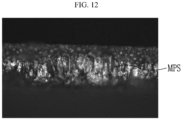
- FIG. 12 is an image with respect to a cross-section of the laser-cut positive electrode plate
- FIG. 13 is a Raman mapping image with respect to a cutting cross-section of the laser-cut positive electrode plate of FIG. 12 .
- the positive active material was melted by the heat and the melted and pressed shape (MPS) observed in the same way.
- FIG. 14 shows, as a Comparative Example, a graph showing the result of Raman spectrum analysis in a cross-section of a positive electrode plate that is physically cut
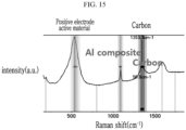
- FIG. 15 shows, as an embodiment, a graph showing the result of Raman spectrum analysis in a cross-section of the laser-cut positive electrode plate.
- the results of Raman spectrum analysis are expressed as the relative value (a.u) of intensity with respect to Raman shift.
- FIG. 14 shows, as a Comparative Example, a graph showing the result of Raman spectrum analysis in a cross-section of a positive electrode plate that is physically cut
- FIG. 15 shows, as an embodiment, the result of Raman spectrum analysis in the cross-section of the laser-cut positive electrode plate 11.
- the laser-cutting it can be observed that a large amount of aluminum (Al) composite is created in the middle part of the thickness direction (vertical direction in FIG. 12 ) of the positive electrode active material.
- the aluminum composite included and observed in the positive active material may prevent damage to the edge on the cross-section of the positive electrode plate 11, that is, prevent the positive active material from being falling off, and thereby may prevent a short circuit caused by the fallen positive active material.
- the inactivation area 114 provided on the edge of the positive electrode plate 11 may be formed in the positive active material layer, like the structures formed on the cross-section of the laser-cutting by irradiating laser on the edge.
- the inactivation area 114 may serve to inactivate the movement of lithium ions during charging and discharging of the all-solid-state battery.
- a lithium precipitation layer 135 is not formed in a discharging state, but may be formed in the charging state, as lithium ions pass through a solid electrolyte 12 and precipitate on a first surface of a negative electrode current collector 131, in the activation area 112 of the positive electrode plate 11.
- the lithium ions of the lithium precipitation layer 135 are dissociated, pass through the solid electrolyte layer 12, and move to the activation area 112 of the positive electrode plate 11, such that the lithium precipitation layer 135 disappears.
- the inactivation area 114 Even when charging, in the inactivation area 114, lithium ions do not move to the negative electrode plate 13, and lithium ions dissociated from the lithium precipitation layer 135 during discharging do not move to the inactivation area 114 of the positive electrode plate 11. That is, the inactivation area 114 does not affect charging and discharging. Accordingly, the inactivation area 114 does not participate in the internal short circuit of the all-solid-state battery.
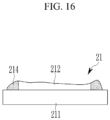
- the positive active material layer may have an activation area 212 formed in a pattern and its outer boundary, that is, a convex raised portion on an edge of the pattern.
- an inactivation area 214 may be formed by irradiating laser on the convex raised portion on an outer boundary edge, and may block the movement of lithium ions when charging and discharging.
- the negative electrode plate 13 may include a negative active material layer 132 formed by applying a negative active material on the cross-section of the negative electrode current collector 131 made of stainless steel (SUS) or nickel-coated copper (Ni-coated Cu).
- SUS stainless steel
- Ni-coated Cu nickel-coated copper
- the negative active material layer 132 is illustrated, but the negative active material layer 132 may not be present.
- the precipitated lithium precipitation layer 135 may act as the negative active material layer.
- only a polymer layer such as a polyvinylidene fluoride layer may be formed on the cross-section of the negative electrode current collector 131.
- the solid electrolyte (SE) layer 12 is laminated on the negative active material layer 132.
- This lamination method may be enabled by direct coating of the solid electrolyte slurry, transfer of the solid electrolyte layer, or lamination bonding between the free-standing solid electrolyte layer and the negative active material layer.
- the buffer film 20 is disposed on a rear surface of the negative electrode current collector 131 of the negative electrode plate 13 in the unit cell, and may be configured to provide an elastic force to correspond to the lithium precipitation layer 135 according to precipitation and dissociation of lithium on the negative active material layer 132 and the negative electrode current collector 131 when charging and discharging.
- the positive electrode plate 11 is provided with an uncoated region 113 protruding outward on a first side, and is provided with an uncoated region 133 protruding outward on a second side.
- the uncoated regions 113 of the positive electrode plates 11 may be stacked to each other to be electrically connected to each other, and the uncoated regions 113 of the negative electrode plates 13 may be stacked to each other to be electrically connected to each other.
Landscapes
- Chemical & Material Sciences (AREA)
- Engineering & Computer Science (AREA)
- Chemical Kinetics & Catalysis (AREA)
- Electrochemistry (AREA)
- General Chemical & Material Sciences (AREA)
- Manufacturing & Machinery (AREA)
- Materials Engineering (AREA)
- Physics & Mathematics (AREA)
- Optics & Photonics (AREA)
- Plasma & Fusion (AREA)
- Mechanical Engineering (AREA)
- Condensed Matter Physics & Semiconductors (AREA)
- General Physics & Mathematics (AREA)
- Inorganic Chemistry (AREA)
- Battery Electrode And Active Subsutance (AREA)
- Secondary Cells (AREA)
Abstract
Description
- The present invention relates to an all-solid-state battery, and more particularly, to an all-solid-state battery having an electrode structure that prevents internal short circuit for stable operation of the cell.
- The all-solid-state battery includes a positive electrode plate, a solid electrolyte layer, and a negative electrode plate. The solid electrolyte layer is a medium that conducts lithium ions. In the case of a lithium precipitation-type all-solid-state battery, lithium ions moved from the positive electrode plate precipitate and accumulate as metal on the negative electrode plate, and lithium metal precipitates on the negative electrode plate when charging, regardless of the presence or absence of an active material in the negative electrode plate.
- An all-solid-state battery having a precipitated negative electrode plate does not have a housing, and during charging, lithium ions moved from the positive electrode plate precipitate on the negative electrode plate, and during discharging, lithium ions accumulated on the negative electrode plate dissociate from the negative electrode plate and move back to the positive electrode plate.
- When charging, lithium precipitates on the negative electrode plate and the volume of the all-solid-state battery expands, so lithium precipitation becomes non-uniform in a free state where no pressure is applied to the all-solid-state battery. As charging and discharging progress, the non-uniform precipitation of lithium is amplified and the solid electrolyte layer is partially broken, which may cause an internal short circuit. In order to solve the non-uniformity of lithium precipitation, pressure is applied to the outside of the all-solid-state battery.
- Meanwhile, the continuously supplied electrode plates are punched into unit electrode plates of appropriate shapes using physical blades, thereby forming positive and negative electrode plates. The positive electrode plate and the negative electrode plate formed by punching may be damaged due to burrs on the edges of the plates. In other words, active material may fall from the edge and cause a short circuit in the cell.
- In addition, the edges of the positive electrode plate may be abnormally activated due to high pressure during cell manufacturing conditions, easily causing short circuit of the cell. Current density is concentrated at the edge of the positive electrode plate compared to other parts. Therefore, it is necessary to manage the edges of the positive electrode plate, which are vulnerable to pressure, as the possibility of short circuits at the edges is higher.
- One embodiment is to provide an all-solid-state battery that prevents short circuit due to damage to the edge of the positive electrode plate. In addition, one embodiment is to provide an all-solid-state battery that prevents short circuit of the edge of the positive electrode plate under high pressure conditions.
- An all-solid-state battery according to an embodiment may include a positive electrode plate provided with an active material on a positive electrode current collector, a solid electrolyte layer disposed on one side of the positive electrode plate, and a negative electrode plate disposed on one side of the solid electrolyte layer, where the positive electrode plate may include an activation area of the active material, and an inactivation area laser-processed on an outer boundary edge of the activation area.
- The positive electrode plate may be formed by laser-cutting the positive electrode current collector on which the active material is continuously coated together with an active material layer.
- The inactivation area may be configured to block entry and exit of lithium ions.
- The inactivation area may be configured to block entry and exit of lithium ions through deformation of the active material crystal structure on the positive electrode plate.
- The inactivation area may be configured to block entry and exit of lithium ions through denaturation of solid electrolyte in the solid electrolyte layer.
- In the inactivation area, the positive electrode current collector may be melted and modified to be contained in the active material.
- The positive electrode plate may be formed by laser-cutting the positive electrode current collector on which the active material is pattern-coated.
- The inactivation area may be formed in a convex raised portion on an outer boundary edge.
- The inactivation area may be formed in a width of 0.1 to 1 mm.
- An all-solid-state battery according to an embodiment is provided with an inactivation area of a predetermined range by laser-cutting the positive electrode plate and by laser-processing the active material on the outer boundary edge of the positive electrode plate, and accordingly, the short circuit due to damage to the edge of the positive electrode plate and the short circuit of the edge of the positive electrode plate due to high pressure condition may be prevented.
-
-
FIG. 1 may be a cross-sectional view of a charged state of an all-solid-state battery according to an embodiment of the present invention. -
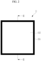
FIG. 2 is a top plan view of a positive electrode plate applied toFIG. 1 . -
FIG. 3 is a cross-sectional view taken along line III-III ofFIG. 2 . -
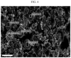
FIG. 4 shows, as a Comparative Example, an image of an energy dispersive X-ray spectroscopy (EDS) with respect to a cross-section of a positive electrode plate that is physically cut. -
FIG. 5 shows, as an embodiment, an image of an electron microscopy (SEM) with respect to a cross-section of the laser-cut positive electrode plate. -
FIG. 6 shows, as an embodiment, an image of an energy dispersive X-ray spectroscopy (EDS) with respect to a cross-section of the laser-cut positive electrode plate. -
FIG. 7 is a graph showing the result of EDS analysis in a first selected area of a cross-section of the laser-cut positive electrode plate ofFIG. 6 . -
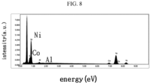
FIG. 8 is a graph showing the result of EDS analysis in a second selected area of a cross-section of the laser-cut positive electrode plate ofFIG. 6 . -
FIG. 9 is a graph showing the result of EDS analysis in a third selected area of a cross-section of the laser-cut positive electrode plate ofFIG. 6 . -
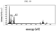
FIG. 10 is a graph showing the result of EDS analysis in a fourth selected area of a cross-section of the laser-cut positive electrode plate ofFIG. 6 . -
FIG. 11 is a graph showing the result of EDS analysis in a fifth selected area of a cross-section of the laser-cut positive electrode plate ofFIG. 6 . -
FIG. 12 is an image with respect to a cross-section of the laser-cut positive electrode plate. -
FIG. 13 is a Raman mapping image with respect to a cross-section of the laser-cut positive electrode plate ofFIG. 12 . -
FIG. 14 shows, as a Comparative Example, a graph showing the result of Raman spectrum analysis in a cross-section of a positive electrode plate that is physically cut. -
FIG. 15 shows, as an embodiment, a graph showing the result of Raman spectrum analysis in a cross-section of the laser-cut positive electrode plate. -
FIG. 16 is a cross-sectional view showing another embodiment of a positive electrode plate applied to an all-solid-state battery according to an embodiment of the present invention. - The present disclosure will be described more fully hereinafter with reference to the accompanying drawings, in which embodiments of the disclosure are shown. As those skilled in the art would realize, the described embodiments may be modified in various different ways, all without departing from the spirit or scope of the present disclosure. The drawings and description are to be regarded as illustrative in nature and not restrictive. Like reference numerals designate like elements throughout the specification.
-
FIG. 1 may be a cross-sectional view of a charged state of an all-solid-state battery according to an embodiment of the present invention. Referring toFIG. 1 , an all-solid-state battery of an embodiment may include apositive electrode plate 11, asolid electrolyte layer 12 disposed on one side of thepositive electrode plate 11, a negative electrode plate 13 disposed on one side of thesolid electrolyte layer 12, and abuffer film 20 disposed on one side of the negative electrode plate 13. - The stacking structure of the
positive electrode plate 11, thesolid electrolyte layer 12, and the negative electrode plate 13 may form a unit cell. The unit cell may be formed as a mono-cell that charges and discharges on one side of the positive electrode plate 11 (not shown). - As shown in
FIG. 1 , the unit cell may be formed as a bi-cell that charges and discharges on both sides of thepositive electrode plate 11. Thepositive electrode plate 11 may be formed by laser-cutting a positive electrodecurrent collector 111 continuously coated with the positive active material together with positiveactive material layers -
FIG. 2 is a top plan view of a positive electrode plate applied toFIG. 1 , andFIG. 3 is a cross-sectional view taken along line III-III ofFIG. 2 . Meanwhile, referring toFIG. 1 to FIG. 3 , thepositive electrode plate 11 may include theactive material layers current collector 111 made of aluminum. - The positive
active material layers activation area 112 of the positive active material and aninactivation area 114 of the positive active material. Theinactivation area 114 is a portion laser-processed on an outer boundary edge of theactivation area 112, and may be formed by irradiating laser on the positive active material of outer boundary of theactivation area 112 after forming the active material layer with the positive active material. - That is, when charging and discharging, whereas the
activation area 112 enables entry and exit of lithium ions, theinactivation area 114 is formed in a predetermined range to block the entry and exit of lithium ions. - The
inactivation area 114 may block the entry and exit of lithium ions through deformation of the active material crystal structure, by being irradiated with laser on the active material layer in thepositive electrode plate 11. In addition, when the focus of the laser brought close to the positive electrodecurrent collector 111, the positive electrodecurrent collector 111 may be melted and deformed such that the component of the positive electrodecurrent collector 111 may be contained in the positive active material, and thereby theinactivation area 114 may block the entry and exit of lithium ions. - As an example, the
inactivation area 114 is formed in a width of 0.1 to 1 mm. If it is less than 0.1 mm, it may not be sufficient to serve as an inactivation area due to the small area of theinactivation area 114, and if it exceeds 1 mm, the capacity of the battery may be deteriorated due to the excessively large area of theinactivation area 114. - In addition, the inactivation area may block the entry and exit of lithium ions through denaturation of the solid electrolyte in the solid electrolyte layer. In this case, the solid electrolyte may be denatured by irradiating a laser to the outside of the solid electrolyte layer, and the solid electrolyte may be denatured by irradiating the laser to the outside of the solid electrolyte layer while the solid electrolyte membrane is laminated to the active material layer of the negative electrode plate.
- The
inactivation area 114 may prevent a short circuit due to the edge of thepositive electrode plate 11, even under the high-pressure condition of the all-solid-state battery. In addition, in order to prevent a short circuit due to a damage of the edge of thepositive electrode plate 11, thepositive electrode plate 11 may be manufactured by laser-cutting, and the laser-cutting will be hereinafter described in detail in comparison with physical cutting. - When the
positive electrode plate 11 is manufactured by laser-cutting, the occurrence of burrs on the edge of thepositive electrode plate 11 may be minimize, and thus the short circuit due to the damage of the edge of thepositive electrode plate 11 may be minimized. -
FIG. 4 shows, as a Comparative Example, an image of an energy dispersive X-ray spectroscopy (EDS) with respect to a cross-section of a positive electrode plate that is physically cut. Table 1 shows the result of EDS analysis on a cross-section of the positive electrode plate ofFIG. 4 that is physically cut by using a blade. The unit is atomic%. - K indicates the K edge of the element. The K edge is caused by electronic transition in the K shell of an atom. Spectroscopically, K is a band of energy that is released after being activated when energy is applied to the element, and this specific signal is used to determine the type of element. Therefore, K represents a specific position value for finding the quantitative value of an element in an energy dispersive X-ray spectroscopy (EDS).
[Table 1 ] Ni K Co K Al K Selected Area 186.4 8.5 5.1 Selected Area 287.5 8.7 3.7 Selected Area 387.0 6.6 6.4 Selected Area 485.8 8.9 5.3 Selected Area 5 90.1 5.0 4.9 -
FIG. 5 shows, as an embodiment, an image of an electron microscopy (SEM) with respect to a cross-section of the laser-cut positive electrode plate, andFIG. 6 shows, as an embodiment, an image of an energy dispersive X-ray spectroscopy (EDS) with respect to a cross-section of the laser-cut positive electrode plate. Table 2 shows the result of EDS analysis on a cross-section of the laser-cutpositive electrode plate 11 ofFIG. 5 andFIG. 6 . The unit is atomic%.[Table 2] Ni K Co K Al K Selected Area 187.7 5.6 6.7 Selected Area 290.0 6.0 4.0 Selected Area 384.5 6.5 9.0 Selected Area 454.6 5.0 40.4 Selected Area 5 53.20 4.1 42.7 -
FIG. 7 to FIG. 11 are graphs showing the result of EDS analysis in the first selected area to the fifth selected area of a cross-section of the laser-cut positive electrode plate. The result of EDS analysis is expressed as a relative value (a.u) of intensity with respect to energy (eV). - Referring to
FIG. 5 to FIG. 11 , the positive active material formed on the cross-section of the laser-cutpositive electrode plate 11 changes due to the irradiation of laser. That is, in the laser-cut cross-section, the positive electrodecurrent collector 111 may be melt and modified to be contained in the positive active material. That is, the positive active material of the laser-cut cross-section may be formed to contain aluminum (Al) composite of the positive electrodecurrent collector 111. - When Table 1 and
FIG. 4 are compared with Table 2 andFIG. 5 , a melted and pressed shape (MPS) of the positive active material due to heat is observed in the laser-cut cross-section, although not found in the physically cut cross-section. - The melted and pressed shape (MPS) may prevent damage to the edge on the laser-cut cross-section of the
positive electrode plate 11, that is, prevent the positive active material from being falling off, and thereby may prevent an internal short circuit caused by the fallen positive active material. - Referring to
FIG. 6 , in the fourth selected area (Selected Area 4) and the fifth selected area (Selected Area 5) in the laser-cut cross-section of thepositive electrode plate 11, aluminum (Al) composite of the positive electrodecurrent collector 111 appears highly due to heat. - That is, whereas the aluminum composite is not more than 10% in the first to third selected areas (Selected
Area 1 to Selected Area 3) located far from the positive electrodecurrent collector 111 on thepositive electrode plate 11, the aluminum composite has been found to be over 20% in the fourth selected area (Selected Area 4) and the fifth selected area (Selected Area 5) adjacent to the positive electrodecurrent collector 111. That is, aluminum composite was found in 40.4% in the fourth selected area (Selected Area 4) in the laser-cut cross-section of thepositive electrode plate 11, and in 42.7% in the fifth selected area (Selected Area 5). -
FIG. 12 is an image with respect to a cross-section of the laser-cut positive electrode plate, andFIG. 13 is a Raman mapping image with respect to a cutting cross-section of the laser-cut positive electrode plate ofFIG. 12 . Referring toFIG. 12 andFIG. 13 , in the laser-cut cross-section of thepositive electrode plate 11, the positive active material was melted by the heat and the melted and pressed shape (MPS) observed in the same way. - The melted and pressed shape (MPS) may prevent damage to the edge on the laser-cut cross-section of the
positive electrode plate 11, that is, prevent the positive active material from being falling off, and thereby may prevent an internal short circuit caused by the fallen positive active material. -
FIG. 14 shows, as a Comparative Example, a graph showing the result of Raman spectrum analysis in a cross-section of a positive electrode plate that is physically cut, andFIG. 15 shows, as an embodiment, a graph showing the result of Raman spectrum analysis in a cross-section of the laser-cut positive electrode plate. The results of Raman spectrum analysis are expressed as the relative value (a.u) of intensity with respect to Raman shift. - Referring to
FIG. 12 to FIG. 15 ,FIG. 14 shows, as a Comparative Example, a graph showing the result of Raman spectrum analysis in a cross-section of a positive electrode plate that is physically cut, andFIG. 15 shows, as an embodiment, the result of Raman spectrum analysis in the cross-section of the laser-cutpositive electrode plate 11. - Referring to the Raman spectrum analysis, unlike the physically-cut cross-section (see
FIG. 14 ), a new peak occurred at Raman shift 1100cm-1 in the laser-cut cross-section (seeFIG. 15 ). It may be seen that this peak is a peak related to aluminum (Al) composite. - In addition, after the laser-cutting, it can be observed that a large amount of aluminum (Al) composite is created in the middle part of the thickness direction (vertical direction in
FIG. 12 ) of the positive electrode active material. The aluminum composite included and observed in the positive active material may prevent damage to the edge on the cross-section of thepositive electrode plate 11, that is, prevent the positive active material from being falling off, and thereby may prevent a short circuit caused by the fallen positive active material. - Meanwhile, the
inactivation area 114 provided on the edge of thepositive electrode plate 11 may be formed in the positive active material layer, like the structures formed on the cross-section of the laser-cutting by irradiating laser on the edge. Theinactivation area 114 may serve to inactivate the movement of lithium ions during charging and discharging of the all-solid-state battery. - Referring back to
FIG. 1 , alithium precipitation layer 135 is not formed in a discharging state, but may be formed in the charging state, as lithium ions pass through asolid electrolyte 12 and precipitate on a first surface of a negative electrode current collector 131, in theactivation area 112 of thepositive electrode plate 11. When discharging, the lithium ions of thelithium precipitation layer 135 are dissociated, pass through thesolid electrolyte layer 12, and move to theactivation area 112 of thepositive electrode plate 11, such that thelithium precipitation layer 135 disappears. - Even when charging, in the
inactivation area 114, lithium ions do not move to the negative electrode plate 13, and lithium ions dissociated from thelithium precipitation layer 135 during discharging do not move to theinactivation area 114 of thepositive electrode plate 11. That is, theinactivation area 114 does not affect charging and discharging. Accordingly, theinactivation area 114 does not participate in the internal short circuit of the all-solid-state battery. -
FIG. 16 is a cross-sectional view showing another embodiment of a positive electrode plate applied to an all-solid-state battery according to an embodiment of the present invention. Referring toFIG. 16 , apositive electrode plate 21 may be formed by laser-cutting a positive electrodecurrent collector 211 pattern-coated with the positive active material. - In this case, the positive active material layer may have an
activation area 212 formed in a pattern and its outer boundary, that is, a convex raised portion on an edge of the pattern. At this time, aninactivation area 214 may be formed by irradiating laser on the convex raised portion on an outer boundary edge, and may block the movement of lithium ions when charging and discharging. - Referring back to
FIG. 1 , the negative electrode plate 13 may include a negativeactive material layer 132 formed by applying a negative active material on the cross-section of the negative electrode current collector 131 made of stainless steel (SUS) or nickel-coated copper (Ni-coated Cu). - For convenience, here, the negative
active material layer 132 is illustrated, but the negativeactive material layer 132 may not be present. In this case, the precipitatedlithium precipitation layer 135 may act as the negative active material layer. In addition, only a polymer layer such as a polyvinylidene fluoride layer may be formed on the cross-section of the negative electrode current collector 131. - The solid electrolyte (SE)
layer 12 is laminated on the negativeactive material layer 132. This lamination method may be enabled by direct coating of the solid electrolyte slurry, transfer of the solid electrolyte layer, or lamination bonding between the free-standing solid electrolyte layer and the negative active material layer. - The
buffer film 20 is disposed on a rear surface of the negative electrode current collector 131 of the negative electrode plate 13 in the unit cell, and may be configured to provide an elastic force to correspond to thelithium precipitation layer 135 according to precipitation and dissociation of lithium on the negativeactive material layer 132 and the negative electrode current collector 131 when charging and discharging. - In addition, the
positive electrode plate 11 is provided with anuncoated region 113 protruding outward on a first side, and is provided with anuncoated region 133 protruding outward on a second side. When unit cells are stacked to form a module of the all-solid-state battery, theuncoated regions 113 of thepositive electrode plates 11 may be stacked to each other to be electrically connected to each other, and theuncoated regions 113 of the negative electrode plates 13 may be stacked to each other to be electrically connected to each other. - While this disclosure has been described in connection with what is presently considered to be practical embodiments, it is to be understood that the disclosure is not limited to the disclosed embodiments, but, on the contrary, is intended to cover various modifications and equivalent arrangements included within the spirit and scope of the appended claims.
- Description of symbols - 11, 21: positive electrode plate 12: solid electrolyte layer 13: negative electrode plate 20: buffer film 111, 211: positive electrode current collector 112, 212: activation area 114, 214: inactivation area 131: negative electrode current collector 132: negative active material layer 135: lithium precipitation layer
Claims (9)
- An all-solid-state battery, comprising:a positive electrode plate provided with an active material on a positive electrode current collector;a solid electrolyte layer disposed on one side of the positive electrode plate; anda negative electrode plate disposed on one side of the solid electrolyte layer,wherein the positive electrode plate comprisesan activation area of the active material; andan inactivation area laser-processed on an outer boundary edge of the activation area.
- The all-solid-state battery of claim 1, wherein the positive electrode plate is formed by laser-cutting the positive electrode current collector on which the active material is continuously coated together with an active material layer.
- The all-solid-state battery of claim 1, wherein the inactivation area is configured to block entry and exit of lithium ions.
- The all-solid-state battery of claim 1, wherein the inactivation area is configured to block entry and exit of lithium ions through deformation of the active material crystal structure on the positive electrode plate.
- The all-solid-state battery of claim 1, wherein the inactivation area is configured to block entry and exit of lithium ions through denaturation of solid electrolyte in the solid electrolyte layer.
- The all-solid-state battery of claim 1, wherein, in the inactivation area, the positive electrode current collector is melted and modified to be contained in the active material.
- The all-solid-state battery of claim 1, wherein the positive electrode plate is formed by laser-cutting the positive electrode current collector on which the active material is pattern-coated.
- The all-solid-state battery of claim 7, wherein the inactivation area is formed in a convex raised portion on an outer boundary edge.
- The all-solid-state battery of claim 1, wherein the inactivation area is formed in a width of 0.1 to 1 mm.
Applications Claiming Priority (2)
| Application Number | Priority Date | Filing Date | Title |
|---|---|---|---|
| KR1020220019186A KR102889756B1 (en) | 2022-02-14 | 2022-02-14 | All solid battery |
| PCT/KR2022/018049 WO2023153591A1 (en) | 2022-02-14 | 2022-11-16 | All solid battery |
Publications (2)
| Publication Number | Publication Date |
|---|---|
| EP4481881A1 true EP4481881A1 (en) | 2024-12-25 |
| EP4481881A4 EP4481881A4 (en) | 2026-03-18 |
Family
ID=87564453
Family Applications (1)
| Application Number | Title | Priority Date | Filing Date |
|---|---|---|---|
| EP22926189.6A Pending EP4481881A4 (en) | 2022-02-14 | 2022-11-16 | SOLID BATTERY |
Country Status (6)
| Country | Link |
|---|---|
| US (1) | US20250158136A1 (en) |
| EP (1) | EP4481881A4 (en) |
| JP (1) | JP2025505271A (en) |
| KR (1) | KR102889756B1 (en) |
| CN (1) | CN119032448A (en) |
| WO (1) | WO2023153591A1 (en) |
Families Citing this family (2)
| Publication number | Priority date | Publication date | Assignee | Title |
|---|---|---|---|---|
| WO2025173426A1 (en) * | 2024-02-14 | 2025-08-21 | 株式会社Gsユアサ | Power storage element |
| KR20250151681A (en) * | 2024-04-12 | 2025-10-22 | 삼성에스디아이 주식회사 | all-solid-state battery and a method for manufacturing it |
Family Cites Families (12)
| Publication number | Priority date | Publication date | Assignee | Title |
|---|---|---|---|---|
| KR101093306B1 (en) * | 2007-05-18 | 2011-12-14 | 주식회사 엘지화학 | Manufacturing Method of Lithium Secondary Battery Electrode Using Fiber Pulse Laser |
| KR101660203B1 (en) * | 2011-01-28 | 2016-09-26 | 도요타지도샤가부시키가이샤 | Secondary battery manufacturing method, and electrode sheet cutting apparatus |
| JPWO2013035519A1 (en) * | 2011-09-09 | 2015-03-23 | 株式会社村田製作所 | All-solid battery and method for manufacturing the same |
| KR102052589B1 (en) * | 2013-04-01 | 2019-12-05 | 삼성에스디아이 주식회사 | Electrode, rechargeable battery and fablicating method of electrode |
| KR101664244B1 (en) * | 2013-11-01 | 2016-10-10 | 주식회사 엘지화학 | Method forming electrode surface pattern and the electrode manufactured by the method and secondary battery including the same |
| US10164289B2 (en) * | 2014-12-02 | 2018-12-25 | Polyplus Battery Company | Vitreous solid electrolyte sheets of Li ion conducting sulfur-based glass and associated structures, cells and methods |
| TWI581488B (en) * | 2015-10-13 | 2017-05-01 | Metal Ind Res & Dev Ct | Method for manufacturing negative electrode plate of secondary battery |
| JP6319335B2 (en) * | 2016-01-18 | 2018-05-09 | トヨタ自動車株式会社 | Manufacturing method of all solid state battery |
| JP6519570B2 (en) * | 2016-11-17 | 2019-05-29 | トヨタ自動車株式会社 | Separator integrated electrode plate, electrode plate pair, laminated type storage element, and method of manufacturing separator integrated electrode plate |
| KR102440683B1 (en) * | 2017-09-04 | 2022-09-05 | 현대자동차주식회사 | All-solid battery and method for manufacturing the same |
| DE102018222129A1 (en) * | 2018-12-18 | 2020-06-18 | Fraunhofer-Gesellschaft zur Förderung der angewandten Forschung e.V. | Cathode unit and method for manufacturing a cathode unit |
| CN112117438A (en) * | 2020-09-27 | 2020-12-22 | 蜂巢能源科技有限公司 | A negative electrode sheet and its preparation method and solid-state battery |
-
2022
- 2022-02-14 KR KR1020220019186A patent/KR102889756B1/en active Active
- 2022-11-16 CN CN202280094822.3A patent/CN119032448A/en active Pending
- 2022-11-16 EP EP22926189.6A patent/EP4481881A4/en active Pending
- 2022-11-16 WO PCT/KR2022/018049 patent/WO2023153591A1/en not_active Ceased
- 2022-11-16 US US18/837,106 patent/US20250158136A1/en active Pending
- 2022-11-16 JP JP2024547793A patent/JP2025505271A/en active Pending
Also Published As
| Publication number | Publication date |
|---|---|
| KR20230122476A (en) | 2023-08-22 |
| EP4481881A4 (en) | 2026-03-18 |
| KR102889756B1 (en) | 2025-11-20 |
| JP2025505271A (en) | 2025-02-21 |
| CN119032448A (en) | 2024-11-26 |
| WO2023153591A1 (en) | 2023-08-17 |
| US20250158136A1 (en) | 2025-05-15 |
Similar Documents
| Publication | Publication Date | Title |
|---|---|---|
| KR102894754B1 (en) | Method for manufacturing secondary battery and secondary battery using the same | |
| US20250158136A1 (en) | Solid state battery | |
| US10424815B2 (en) | Battery and battery manufacturing method | |
| CN111527638B (en) | Method for manufacturing all-solid-state batteries | |
| US20220184738A1 (en) | Tight-Contact Jig for Secondary Battery Tab Laser Welding and Welding Method | |
| KR102693188B1 (en) | Secondary battery | |
| US10559808B2 (en) | Lithium secondary battery having improved safety by using bimetal tab | |
| JP7117588B2 (en) | All-solid-state battery and manufacturing method thereof | |
| US20110311877A1 (en) | Metal foil for secondary battery and secondary battery | |
| US10770714B2 (en) | Electrode manufacturing method for improving battery capacity and electrode manufactured thereby | |
| US20050112469A1 (en) | Lithium cell and method for manufacturing the same | |
| EP2368284A1 (en) | Battery manufacturing | |
| EP4213278B1 (en) | Secondary battery | |
| KR101147241B1 (en) | Electrode assembly, rechargeable battery, and fabricating methode of electrode used thereof | |
| KR20190001429A (en) | Welding method of electrode tap and cable-type secondary battery comprising electrode welded by the same | |
| CN111095609A (en) | Laser ablation for manufacturing battery cells | |
| JP4484497B2 (en) | Square sealed secondary battery and manufacturing method thereof | |
| JP3578303B2 (en) | Method for producing electrode of sealed prismatic battery | |
| JP6958475B2 (en) | Electrode plate manufacturing method | |
| KR20130129837A (en) | Method for treating surface of electrode by laser irradiation | |
| KR102052589B1 (en) | Electrode, rechargeable battery and fablicating method of electrode | |
| KR20210034963A (en) | Method for manufacturing cylindrical secondary battery | |
| KR102818419B1 (en) | Method for fabricating lead tab of secondary battery | |
| KR20240100193A (en) | Apparatus for manufacturing secondary battery, method for manufacturing secondary battery using the same | |
| US20210376306A1 (en) | Electrodes for Batteries and Methods for Making Same |
Legal Events
| Date | Code | Title | Description |
|---|---|---|---|
| STAA | Information on the status of an ep patent application or granted ep patent |
Free format text: STATUS: THE INTERNATIONAL PUBLICATION HAS BEEN MADE |
|
| PUAI | Public reference made under article 153(3) epc to a published international application that has entered the european phase |
Free format text: ORIGINAL CODE: 0009012 |
|
| STAA | Information on the status of an ep patent application or granted ep patent |
Free format text: STATUS: REQUEST FOR EXAMINATION WAS MADE |
|
| 17P | Request for examination filed |
Effective date: 20240911 |
|
| AK | Designated contracting states |
Kind code of ref document: A1 Designated state(s): AL AT BE BG CH CY CZ DE DK EE ES FI FR GB GR HR HU IE IS IT LI LT LU LV MC ME MK MT NL NO PL PT RO RS SE SI SK SM TR |
|
| DAV | Request for validation of the european patent (deleted) | ||
| DAX | Request for extension of the european patent (deleted) | ||
| A4 | Supplementary search report drawn up and despatched |
Effective date: 20260217 |
|
| RIC1 | Information provided on ipc code assigned before grant |
Ipc: H01M 10/0585 20100101AFI20260211BHEP Ipc: H01M 10/0562 20100101ALI20260211BHEP Ipc: H01M 10/052 20100101ALI20260211BHEP Ipc: H01M 10/42 20060101ALI20260211BHEP Ipc: H01M 4/13 20100101ALI20260211BHEP Ipc: H01M 4/139 20100101ALI20260211BHEP Ipc: H01M 10/0525 20100101ALI20260211BHEP |