EP4481861A1 - Current collector, electrode sheet, electrode assembly, battery cell, battery and electric apparatus - Google Patents
Current collector, electrode sheet, electrode assembly, battery cell, battery and electric apparatus Download PDFInfo
- Publication number
- EP4481861A1 EP4481861A1 EP23875916.1A EP23875916A EP4481861A1 EP 4481861 A1 EP4481861 A1 EP 4481861A1 EP 23875916 A EP23875916 A EP 23875916A EP 4481861 A1 EP4481861 A1 EP 4481861A1
- Authority
- EP
- European Patent Office
- Prior art keywords
- current collector
- battery cell
- support layer
- conductive layer
- thickness
- Prior art date
- Legal status (The legal status is an assumption and is not a legal conclusion. Google has not performed a legal analysis and makes no representation as to the accuracy of the status listed.)
- Pending
Links
Images


Classifications
-
- H—ELECTRICITY
- H01—ELECTRIC ELEMENTS
- H01M—PROCESSES OR MEANS, e.g. BATTERIES, FOR THE DIRECT CONVERSION OF CHEMICAL ENERGY INTO ELECTRICAL ENERGY
- H01M4/00—Electrodes
- H01M4/02—Electrodes composed of, or comprising, active material
- H01M4/64—Carriers or collectors
- H01M4/66—Selection of materials
- H01M4/661—Metal or alloys, e.g. alloy coatings
-
- H—ELECTRICITY
- H01—ELECTRIC ELEMENTS
- H01M—PROCESSES OR MEANS, e.g. BATTERIES, FOR THE DIRECT CONVERSION OF CHEMICAL ENERGY INTO ELECTRICAL ENERGY
- H01M10/00—Secondary cells; Manufacture thereof
- H01M10/04—Construction or manufacture in general
- H01M10/0422—Cells or battery with cylindrical casing
-
- H—ELECTRICITY
- H01—ELECTRIC ELEMENTS
- H01M—PROCESSES OR MEANS, e.g. BATTERIES, FOR THE DIRECT CONVERSION OF CHEMICAL ENERGY INTO ELECTRICAL ENERGY
- H01M10/00—Secondary cells; Manufacture thereof
- H01M10/04—Construction or manufacture in general
- H01M10/0431—Cells with wound or folded electrodes
-
- H—ELECTRICITY
- H01—ELECTRIC ELEMENTS
- H01M—PROCESSES OR MEANS, e.g. BATTERIES, FOR THE DIRECT CONVERSION OF CHEMICAL ENERGY INTO ELECTRICAL ENERGY
- H01M10/00—Secondary cells; Manufacture thereof
- H01M10/05—Accumulators with non-aqueous electrolyte
- H01M10/052—Li-accumulators
- H01M10/0525—Rocking-chair batteries, i.e. batteries with lithium insertion or intercalation in both electrodes; Lithium-ion batteries
-
- H—ELECTRICITY
- H01—ELECTRIC ELEMENTS
- H01M—PROCESSES OR MEANS, e.g. BATTERIES, FOR THE DIRECT CONVERSION OF CHEMICAL ENERGY INTO ELECTRICAL ENERGY
- H01M10/00—Secondary cells; Manufacture thereof
- H01M10/05—Accumulators with non-aqueous electrolyte
- H01M10/058—Construction or manufacture
- H01M10/0587—Construction or manufacture of accumulators having only wound construction elements, i.e. wound positive electrodes, wound negative electrodes and wound separators
-
- H—ELECTRICITY
- H01—ELECTRIC ELEMENTS
- H01M—PROCESSES OR MEANS, e.g. BATTERIES, FOR THE DIRECT CONVERSION OF CHEMICAL ENERGY INTO ELECTRICAL ENERGY
- H01M4/00—Electrodes
- H01M4/02—Electrodes composed of, or comprising, active material
- H01M4/13—Electrodes for accumulators with non-aqueous electrolyte, e.g. for lithium-accumulators; Processes of manufacture thereof
-
- H—ELECTRICITY
- H01—ELECTRIC ELEMENTS
- H01M—PROCESSES OR MEANS, e.g. BATTERIES, FOR THE DIRECT CONVERSION OF CHEMICAL ENERGY INTO ELECTRICAL ENERGY
- H01M4/00—Electrodes
- H01M4/02—Electrodes composed of, or comprising, active material
- H01M4/64—Carriers or collectors
- H01M4/66—Selection of materials
- H01M4/665—Composites
- H01M4/667—Composites in the form of layers, e.g. coatings
-
- H—ELECTRICITY
- H01—ELECTRIC ELEMENTS
- H01M—PROCESSES OR MEANS, e.g. BATTERIES, FOR THE DIRECT CONVERSION OF CHEMICAL ENERGY INTO ELECTRICAL ENERGY
- H01M2220/00—Batteries for particular applications
- H01M2220/20—Batteries in motive systems, e.g. vehicle, ship, plane
-
- Y—GENERAL TAGGING OF NEW TECHNOLOGICAL DEVELOPMENTS; GENERAL TAGGING OF CROSS-SECTIONAL TECHNOLOGIES SPANNING OVER SEVERAL SECTIONS OF THE IPC; TECHNICAL SUBJECTS COVERED BY FORMER USPC CROSS-REFERENCE ART COLLECTIONS [XRACs] AND DIGESTS
- Y02—TECHNOLOGIES OR APPLICATIONS FOR MITIGATION OR ADAPTATION AGAINST CLIMATE CHANGE
- Y02E—REDUCTION OF GREENHOUSE GAS [GHG] EMISSIONS, RELATED TO ENERGY GENERATION, TRANSMISSION OR DISTRIBUTION
- Y02E60/00—Enabling technologies; Technologies with a potential or indirect contribution to GHG emissions mitigation
- Y02E60/10—Energy storage using batteries
-
- Y—GENERAL TAGGING OF NEW TECHNOLOGICAL DEVELOPMENTS; GENERAL TAGGING OF CROSS-SECTIONAL TECHNOLOGIES SPANNING OVER SEVERAL SECTIONS OF THE IPC; TECHNICAL SUBJECTS COVERED BY FORMER USPC CROSS-REFERENCE ART COLLECTIONS [XRACs] AND DIGESTS
- Y02—TECHNOLOGIES OR APPLICATIONS FOR MITIGATION OR ADAPTATION AGAINST CLIMATE CHANGE
- Y02P—CLIMATE CHANGE MITIGATION TECHNOLOGIES IN THE PRODUCTION OR PROCESSING OF GOODS
- Y02P70/00—Climate change mitigation technologies in the production process for final industrial or consumer products
- Y02P70/50—Manufacturing or production processes characterised by the final manufactured product
Definitions
- This application relates to the field of battery technologies, and specifically to a battery cell, a battery, and an electric device.
- Batteries are widely used in various fields such as portable electronic devices, electric vehicles, electric tools, drones, and energy storage devices. As the application fields expand, the reliability of batteries has become one of the key concerns for users.
- Embodiments of this application provide a battery cell, a battery, an electric device, to improve reliability of battery cells.
- an embodiment of this application provides a battery cell, where the battery cell is of a cylindrical structure, the battery cell includes an electrode assembly, the electrode assembly is of a wound structure, the electrode assembly includes an electrode plate, and the electrode plate includes a support layer and a conductive layer.
- the conductive layer is disposed on at least one side of the support layer. Elongation of the support layer is greater than elongation of the conductive layer, and in the thickness direction of the current collector, the support layer has a thickness greater than a total thickness of the conductive layer of the current collector.
- the thickness proportion of the support layer is greater than the thickness proportion of the conductive layer, allowing for good extensibility of the insulating layer, such that the current collector can withstand a large swelling force without breaking. This allows the current collector to meet the requirement on swelling alleviation of a battery cell with high-energy density, improving the reliability of the battery cell with high-energy density.
- the thickness of the support layer is H 1
- the total thickness of the conductive layer of the current collector is H 2 , H 1 and H 2 satisfying H 1 /H 2 ⁇ 50.
- the thickness of the support layer is a slightly larger than the total thickness of the conductive layer, and a battery cell manufactured using such current collector is difficult to meet the requirements of both a high energy density and a high rate. If 20 ⁇ H 1 /H 2 ⁇ 50, the thickness of the support layer is greatly larger than the total thickness of the conductive layer. This may result in, under the condition that the thickness of the current collector is given, a small total thickness of the conductive layer, thereby causing a low current flow capability of the conductive layer.
- 2 ⁇ H 1 /H 2 ⁇ 20 allows the current collector to have good strength and elongation of and the conductive layer of the current collector to have a good current flow capability.
- the battery cell manufactured using such current collector can meet the requirements of both a high energy density and a high rate.
- the thickness of the support layer in the thickness direction of the current collector, is H 1 , satisfying 1 ⁇ m ⁇ H 1 ⁇ 20 ⁇ m.
- the strength and elongation of the support layer are both good, such that the current collector has good strength and elongation to meet the requirement on swelling alleviation of a battery cell with high energy density.
- the total thickness of the conductive layer of the current collector is H 2 , satisfying 0.1 ⁇ m ⁇ H 2 ⁇ 10 ⁇ m.
- 0.5 ⁇ m ⁇ H 1 ⁇ 5 ⁇ m allows the conductive layer of the current collector to have better electrical conductivity to meet the high rate requirement of the battery cell.
- a surface of the conductive layer facing the support layer is provided with a protrusion, the protrusion being inserted in the support layer.
- the protrusion disposed on the surface of the conductive layer facing the support layer is inserted in the support layer, which can increase the connection area between the conductive layer and the support layer and helps improve the connection stability between the conductive layer and the support layer.
- the protrusion disposed on the surface of the conductive layer facing the support layer is inserted in the support layer, which can enhance the connection force between the conductive layer and the support layer.
- the connection force can restrain swelling of the conductive layer and support layer, which helps alleviate swelling of the current collector and increase elongation of the current collector. In this way, the current collector can meet the requirement on swelling alleviation of a battery cell with high energy density, thereby improving the reliability of the battery cell with high energy density.
- the support layer being an insulating layer can reduce the weight of the current collector, thereby reducing the weight of the battery cell manufactured using the current collector.
- a material of the insulating layer includes at least one of polypropylene, polyethylene, and polyethylene terephthalate.
- the conductive layer is made of copper or aluminum.
- copper or aluminum has good electrical conductivity, which helps improve the reliability of a battery cell manufactured using the current collector.
- the conductive layer in the thickness direction of the current collector, is disposed on each of two sides of the support layer.
- an active substance layer can be disposed on each of two sides of the current collector, which helps increase the energy density of a battery cell including the current collector.
- the electrode plate includes an active substance layer, and in the thickness direction of the current collector, the active substance layer is disposed on a side of the conductive layer back away from the support layer.
- the electrode assembly includes such two electrode plates with opposite polarities.
- an embodiment of this application further provides a battery including the battery cell provided in any one of the embodiments of the first aspect.
- the battery cell provided in any one of the embodiments of the second aspect has good reliability, and a battery including the battery cell also has good reliability.
- an embodiment of this application further provides an electric device including the battery provided in the embodiments of the first aspect.
- the battery provided in the embodiments of a fifth aspect has good reliability, and an electric device to which the battery provides electrical energy has good reliability of electricity supply.
- orientations or positional relationships as indicated are orientations or positional relationships based on the accompanying drawings, or conventional orientations or positional relationships of products of this application, or orientations or positional relationships as conventionally understood by persons skilled in the art, and the orientations or positional relationships as indicated are merely for ease and brevity of description of this application rather than indicating or implying that the apparatuses or elements mentioned must have specific orientations or must be constructed or manipulated according to specific orientations, and therefore cannot be understood as limitations on this application.
- the terms “first”, “second”, “third”, and the like are merely intended for distinguishing purposes and shall not be understood as any indication or implication of relative importance.
- Traction batteries have been not only used in energy storage power supply systems such as hydroelectric power plants, thermal power plants, wind power plants, and solar power plants, but also widely used in many other fields including electric transportation tools such as electric bicycles, electric motorcycles, and electric vehicles, military equipment, and aerospace. With the continuous expansion of application fields of traction batteries, market demands for traction batteries are also increasing.
- the battery mentioned in the embodiments of this application is a single physical module that includes one or more battery cells for providing a higher voltage and capacity.
- the battery mentioned in this application may include a battery module, a battery pack, or the like.
- a battery typically includes a box configured to enclose one or more battery cells. The box can prevent liquids or other foreign matter from affecting charging or discharging of the battery cell.
- the battery cell includes a housing and an electrode assembly, where the electrode assembly is accommodated in the housing.
- the electrode assembly includes a separator and two electrode plates with opposite polarities.
- the two electrode plates with opposite polarities are positive electrode plate and negative electrode plate.
- the battery cell mainly relies on movement of metal ions between a positive electrode plate and a negative electrode plate to work.
- the electrode plate includes a current collector and an active substance layer, where the active substance layer is applied to a surface of the current collector.
- the housing of the battery cell has a limited internal space, that is, a large group margin, resulting in a small gap between the positive electrode plate and negative electrode plate and a limited swelling space of the electrode plate during charging of the battery cell.
- one electrode plate withstands a large swelling force after the battery cell of high energy density is charged, and is likely to be damaged and broken, and the broken electrode plate pierces the separator to abut against the adjacent electrode plate, which is prone to short circuit and leads to thermal runaway of the battery cell.
- the electrode plate cannot withstand a large swelling force and breaks, which results in low reliability of the battery cell.
- an embodiment of this application provides a battery cell.
- the battery cell is of a cylindrical structure, and the battery cell includes an electrode assembly.
- the electrode assembly includes an electrode plate, the electrode plate includes a current collector, and the current collector includes a support layer and a conductive layer.
- the conductive layer is disposed on at least one side of the support layer, elongation of the support layer is greater than elongation of the conductive layer, and the support layer has a thickness greater than a total thickness of the conductive layer of the current collector.
- the thickness proportion of the support layer is greater than the total thickness proportion of the conductive layer, allowing for good extensibility of the insulating layer, such that the current collector can withstand a large swelling force without breaking. This allows the current collector to meet the requirement on swelling alleviation of the battery cell with high-energy density, improving the reliability of the battery cell with high-energy density.
- the current collector disclosed by the embodiments of this application can be used for manufacturing an electrode plate and a battery cell.
- the battery cell including the electrode plate provided in the embodiments of this application may be used without limitation in electric devices such as vehicles, ships, or aircrafts.
- a battery cell, battery, or the like manufactured using the electrode plate disclosed in this application may be used to form a power system of the electric device. This is conducive to alleviating the problem that the electrode plate cannot withstand a large swelling force without breaking, or will be broken, thereby improving the reliability of the battery.
- the embodiments of this application provide an electric device that uses a battery as the power supply.
- the electric device may be, but is not limited to, a mobile phone, a tablet, a laptop computer, an electric toy, an electric bicycle, an electric vehicle, a ship, or a spacecraft.
- the electric toy may be a fixed or mobile electric toy, for example, a game console, an electric toy car, an electric toy ship, and an electric toy airplane.
- the spacecraft may include an airplane, a rocket, a space shuttle, a spaceship, and the like.
- FIG. 1 is a schematic structural diagram of a vehicle 1000 according to some embodiments of this application.
- the vehicle 1000 may be a fossil fuel vehicle, a natural-gas vehicle, or a new energy vehicle, where the new energy vehicle may be a battery electric vehicle, a hybrid electric vehicle, a range-extended vehicle, or the like.
- the vehicle 1000 is provided with a battery 100 inside, where the battery 100 may be disposed at the bottom, front or rear of the vehicle 1000.
- the battery 100 may be configured to supply power to the vehicle 1000.
- the battery 100 may be used as an operational power source for the vehicle 1000.
- the vehicle 1000 may further include a controller 200 and a motor 300, where the controller 200 is configured to control the battery 100 to supply power to the motor 300, for example, to satisfy power needs of start, navigation, and driving of the vehicle 1000.
- the battery 100 can be used as not only the operational power source for the vehicle 1000 but also a driving power source for the vehicle 1000, replacing or partially replacing fossil fuel or natural gas to provide driving traction for the vehicle 1000.
- the second portion 12 may be a hollow structure with one end open, and the first portion 11 may be a plate structure, where the first portion 11 covers the open side of the second portion 12 for the first portion 11 and the second portion 12 to jointly define an accommodating space; alternatively, the first portion 11 and the second portion 12 may both be hollow structures with one side open, where the open side of the first portion 11 is engaged with the open side of the second portion 12.
- the box 10 formed by the first portion 11 and the second portion 12 may have a variety of shapes, for example, cylinder or cuboid.
- FIG. 3 is a schematic structural exploded view of a battery cell 20 according to some embodiments of this application.
- the battery cell 20 refers to a smallest element constituting the battery 100.
- the battery cell 20 includes a housing 21, an electrode assembly 22, and other functional components.
- the electrode assembly 22 is accommodated in the housing 21.
- the electrode terminal 213 may be configured to be electrically connected to the electrode assembly 22 for outputting or inputting electrical energy of the battery cell 20.
- the end cover 211 may further be provided with a pressure relief mechanism for releasing internal pressure when the internal pressure or a temperature of the battery cell 20 reaches a threshold.
- the end cover 211 may also be made of various materials, such as copper, iron, aluminum, stainless steel, aluminum alloy, and plastic, which are not particularly limited in the embodiments of this application.
- an insulator may also be provided on an inner side of the end cover 211. The insulator may be configured to isolate an electrically connected component in the housing body 212 from the end cover 211 to reduce a risk of short circuit.
- the insulator may be made of plastic, rubber, or the like.
- the housing body 212 is an assembly configured to form an internal environment of the battery cell 20 together with the end cover 211, where the formed internal environment may be configured to accommodate the electrode assembly 22, an electrolyte, and other components.
- the housing body 212 and the end cover 211 may be separate components, an opening may be provided on the housing body 212, and the end cover 211 covers the opening to form the internal environment of the battery cell 20.
- the end cover 211 and the housing body 212 are not limited and may also be integrated. Specifically, the end cover 211 and the housing body 212 may form a shared connection surface before other components are disposed inside the housing, and then the housing body 212 is covered with the end cover 211 when inside of the housing body 212 needs to be enclosed.
- the housing body 212 may be of various shapes and sizes, such as a cuboid shape, a cylindrical shape, and a hexagonal prism shape. Specifically, a shape of the housing body 212 may be determined according to a specific shape and size of the electrode assembly 22.
- the housing body 212 may be made of various materials, such as copper, iron, aluminum, stainless steel, aluminum alloy, and plastic, which are not particularly limited in the embodiments of this application.
- the electrode assembly 22 is a component in which electrochemical reactions occur in the battery cell 20.
- the housing body 212 may include one or more electrode assemblies 22.
- the electrode assembly 22 is mainly formed by winding or stacking two electrode plates 221 with opposite polarities, and a separator is generally provided between the two electrode plates 221 with opposite polarities.
- the separator may be made of PP (polypropylene, polypropylene), PE (polyethylene, polyethylene), or the like.
- Portions, of the two electrode plates 221 with opposite polarities, having an active substance form the body portion of the electrode assembly 22, and portions, of the two electrode plates 221 with opposite polarities, without the active substance respectively form tabs, namely, a positive electrode tab and a negative electrode tab.
- the positive electrode tab and the negative electrode tab may both be located at one end of the body portion or be located at two ends of the body portion respectively.
- the electrode plate 221 includes an active substance layer 2211 and a current collector 2212. In the thickness direction X of the current collector, the active substance layer 2211 is disposed at least one side of the current collector 2212.
- the active substance layer 2211 may be disposed on only one side or on both sides of the current collector 2212.
- the material of the active substance layer 2211 varies with the polarity of the electrode plate 221.
- the active substance layer 2211 may be made of lithium cobalt oxide, lithium iron phosphate, lithium ternary, lithium manganese oxide, or the like. If the electrode plate 221 is a negative electrode plate, the active substance layer 2211 may be made of carbon, silicon, or the like.
- the current collector 2212 includes a support layer 22121 and a conductive layer 22122.
- the conductive layer 22122 is disposed on at least one side of the support layer 22121.
- the elongation of the support layer 22121 is greater than the elongation of conductive layer 22122.
- the thickness of the support layer 22121 is greater than the total thickness of the conductive layer 22122 of the current collector 2212.
- the conductive layer 22122 may be disposed on only one side or on both sides of the support layer 22121.
- the conductive layer 22122 may be adhered to the surface of the support layer 22121 in the thickness direction X of the current collector or may be disposed on a side of the support layer 22121 in the thickness direction X of the current collector in another manner of, for example, melting connection.
- the material of the conductive layer 22122 may vary with the polarity of the electrode plate 221. If the electrode plate 221 is a positive electrode plate, the conductive layer 22122 may be made of aluminium, and if the electrode plate 221 is a negative electrode plate, the conductive layer 22122 may be made of copper.
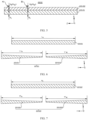
- the support layer 22121 is broken into a first sub-portion 221211 and a second sub-portion 221212 in the length direction Y of the current collector.
- the first sub-portion 221211 has a length of L' 01
- the conductive layer 22122 is broken into a third sub-portion 221221 and a fourth sub-portion 221222 in the length direction Y of the current collector.
- the third sub-portion 221221 has a length of H' 01
- the support layer 22121 and the conductive layer 22122 may further be subjected to the elongating test separately in the width direction Z of the current collector.
- the thickness direction X of the current collector, the length direction Y of the current collector, and the width direction Z of the current collector are perpendicular to each other.
- the thickness of the support layer 22121 refers to the size of the support layer 22121 in the thickness direction X of the current collector.
- the support layer 22121 may be a uniformly thick structure or a non-uniformly thick structure.
- the thickness of the conductive layer 22122 refers to the size of the conductive layer 22122 in the thickness direction X of the current collector.
- the conductive layer 22122 may be a uniformly thick structure or a non-uniformly thick structure.
- the total thickness of the conductive layer 22122 of the current collector 2212 is the thickness of the conductive layer 22122.
- a uniformly thick conductive layer 22122 is disposed on one side of the support layer 22121, the conductive layer 22122 has a thickness of H 21 , and the total thickness H 2 of the conductive layer 22122 of the current collector 2212 is equal to H 21 .
- the total thickness of the conductive layers 22122 of the current collector 2212 is a sum of the thicknesses of the conductive layers 22122 on two sides of the support layer 22121.
- a uniformly thick conductive layer 22122 is disposed on each of two sides of the support layer 22121.
- One conductive layer 22122 has a thickness of H 21
- the other conductive layer has a thickness of H 22
- the thickness of the support layer 22121 should be compared with the total thickness of the conductive layers 22122 of the current collector 2212 in the same position in the width direction Z of the current collector. In the same position in the width direction Z of the current collector, the thickness of the support layer 22121 is greater than the total thickness of the conductive layers 22122 of the current collector 2212. As shown in FIG. 5 , A1 and B1 are two different positions in the width direction Z of the current collector.
- the thickness of the support layer 22121 when the thickness of the support layer 22121 is compared with the total thickness of the conductive layers 22122 of the current collector 2212, the thickness of the support layer 22121 at position A1 and the total thickness of the conductive layers of the current collector 2212 at position A1 should be compared, or the thickness of the support layer 22121 at position B1 and the total thickness of the conductive layers of the current collector 2212 at position B1 should be compared.
- the thickness of the support layer 22121 is greater than the total thickness of the conductive layers 22122 of the current collector 2212, and the differences between the thicknesses of the support layer 22121 and the total thicknesses of the conductive layers 22122 of the current collector 2212 are equal.
- the difference of H 2 -H 1 at position A1 equals the difference of H 2 -H 1 at position B1.
- the differences between the thicknesses of the support layer 22121 and the total thicknesses of the conductive layers 22122 of the current collector 2212 may be equal or different.
- a non-uniformly thick conductive layer 22122 is disposed on a side of the support layer 22121.
- the difference of H 2 -H 1 at position A2 is different from the difference of H 2 -H 1 at position B2.
- A2 and B2 are two different positions in the width direction Z of the current collector.
- the thickness of the support layer 22121 at position A2 and the total thickness of the conductive layer 22122 of the current collector 2212 at position A2 should be compared, or the thickness of the support layer 22121 at position B2 and the total thickness of the conductive layer 22122 of the current collector 2212 at position B2 should be compared instead of comparing the thickness of the support layer 22121 at position A1 with the total thickness of the conductive layer 22122 at position B2.
- the thickness proportion of the support layer 22121 is greater than the thickness proportion of the conductive layer 22122, allowing for good extensibility of the insulating layer, such that the current collector 2212 can withstand a large swelling force without breaking. This allows the current collector 2212 to meet the requirement on swelling alleviation on the battery cell 20 with high-energy density, improving the reliability of the battery cell 20 with high-energy density.
- the support layer 22121 has a thickness of H 1
- the conductive layer 22122 of the current collector 2212 has a total thickness of H 2 , H 1 and H 2 satisfying H 1 /H 2 ⁇ 50.
- the thickness of the support layer 22121 is greater than the total thickness of the conductive layer 22122, that is, H 1 >H 2 , H 1 /H 2 >1.
- H 1 /H 2 may be 5, 10, 15, 20, 25, 30, 35, 40, 45, 50, or the like.
- the support layer 22121 is made of PET
- the conductive layer 22122 is made of aluminium
- the conductive layer 22122 is disposed on each of two sides of the support layer 22121
- the conductive layers 22122 on two sides of the support layer 22121 have the same thickness
- the current collector 2212 has a thickness of H 1 +H 2 being 8 ⁇ m
- different current collectors 2212 of H 1 /H 2 are subjected to an elongating test, to obtain data in Table 1 as follows: Table 1 H 1 /H 2 0.5 1 2 3 4 5 6 8 10 20 30 50 70 Elongation at break of current collector 2.3% 9.5% 30.5% 33.4% 36.7% 43.1% 42.8% 46.3% 44.8% 50.2% 45.2% 45.3% 50.3%
- each current collector 2212 has elongation of 2.3%, which is low and difficult to satisfy the requirement on swelling alleviation of the battery cell 20 with high energy density.
- H 1 /H 2 is 2, 3, 4, 5, 6, 8, 10, 20, 30, 50, or 70
- the current collector 2212 has high elongation.
- H 1 /H 2 is 70
- the conductive layer 22122 has a thickness of only about 0.055 ⁇ m and a quite small current flow capability.
- a larger thickness H 1 of the support layer 22121 indicates better strength and elongation of the current collector 2212.
- a larger total thickness H 2 of the conductive layer 22122 indicates a better current flow capability.
- H 1 /H 2 >50 a percentage of the thickness of the support layer 22121 in the thickness of the current collector 2212 is high, and a percentage of the total thickness of the conductive layer 22122 in the thickness of the current collector 2212 is low, which may result in a small current flow capability of the conductive layer 22122.
- H 1 /H 2 ⁇ 50 can not only allow for better strength and elongation of the current collector 2212, to meet the requirement on swelling alleviation of the battery cell 20 with high-energy density, but also allow for a good current flow capability of the conductive layer 22122, to meet the charge and discharge requirements of the battery cell 20 with high rate.
- H 1 /H 2 may be 2, 4, 6, 8, 12, 14, 16, 18, 19, 20, or the like.
- the current collector 2212 has elongation between 9.5% and 30.5%, which is higher than that when H 1 /H 2 ⁇ 1, but difficult to meet the requirement for a higher energy density of the battery cell on the market.
- H 1 /H 2 of 30, 50, or 70 H 1 /H 2 of 5, 6, 8, 10, or 20 does not show a significant increase in elongation and also results in an excessively large thickness of the support layer 22121 and a small thickness of the conductive layer 22122, impacting the current flow capability.
- the thickness of the support layer 22121 is a slightly larger than the total thickness of the conductive layer 22122, and a battery cell 20 manufactured using such current collector 2212 is difficult to meet the requirements of both a high energy density and a high rate. If 20 ⁇ H 1 /H 2 ⁇ 50, the thickness of the support layer 22121 is greatly larger than the total thickness of the conductive layer 22122. This, in the case of a certain thickness of the current collector 2212, may result in a small total thickness of the conductive layer 22122 and a low current flow capability of the conductive layer 22122, which are also difficult to meet the requirements of both a high energy density and a high rate.
- 2 ⁇ H 1 /H 2 ⁇ 20 allows the current collector 2212 to have good strength and elongation and the conductive layer 22122 of the current collector 2212 to have a good current flow capability.
- the battery cell 20 manufactured using such current collector 2212 can meet the requirements of both a high energy density and a high rate.
- the thickness of the support layer 22121 is H 1 , satisfying 1 ⁇ m ⁇ H 1 ⁇ 20 ⁇ m.
- H 1 may be 1 ⁇ m, 3 ⁇ m, 5 ⁇ m, 6 ⁇ m, 8 ⁇ m, 10 ⁇ m, 13 ⁇ m, 15 ⁇ m, 18 ⁇ m, 20 ⁇ m, or the like.
- H 1 may be 3 ⁇ m, 4 ⁇ m, 4.5 ⁇ m, 7 ⁇ m, 7.5 ⁇ m, 9 ⁇ m, 10.5 ⁇ m, 11 ⁇ m, 12 ⁇ m, 14 ⁇ m, or the like.
- the strength and elongation of the support layer 22121 are both good, resulting in good strength and elongation of the current collector 2212, to meet the requirement on swelling alleviation of the battery cell 20 with high energy density.
- the total thickness of the conductive layer 22122 of the current collector 2212 is H 2 , satisfying 0.1 ⁇ m ⁇ H 2 ⁇ 10 ⁇ m.
- H 2 may be 0.1 ⁇ m 0.5 ⁇ m, 1 ⁇ m, 2 ⁇ m, 3 ⁇ m, 5 ⁇ m, 7 ⁇ m, 9 ⁇ m, 10 ⁇ m, or the like.
- 0.1 ⁇ m>H 2 the current flow capability of the conductive layer 22122 is weak. If H 1 >10 ⁇ m, the conductive layer 22122 has a large thickness, occupying a large space, which may decrease the energy density of the battery cell 20 manufactured using the current collector 2212. Therefore, 0.1 ⁇ m ⁇ H 1 ⁇ 10 ⁇ m allows the conductive layer 22122 of the current collector 2212 to have good electrical conductivity to meet the high rate requirement of the battery cell 20.
- H 2 may be 0.5 ⁇ m, 0.8 ⁇ m, 1.5 ⁇ m, 1.8 ⁇ m, 2.5 ⁇ m, 2.8 ⁇ m, 3.5 ⁇ m, 3.8 ⁇ m, 4 ⁇ m, 4.5 ⁇ m, 4.8 ⁇ m, 5 ⁇ m, or the like.
- 0.5 ⁇ m ⁇ H 1 ⁇ 5 ⁇ m allows the conductive layer 22122 of the current collector 2212 to have better electrical conductivity to meet the high rate requirement of the battery cell 20.
- a surface of the conductive layer 22122 facing the support layer 22121 is provided with a protrusion 22123, the protrusion 22123 being inserted in the support layer 22121.
- the surface of the conductive layer 22122 facing the support layer 22121 may be provided with one or more protrusions 22123.
- a plurality of means two or more. In an embodiment in which the surface of the conductive layer 22122 facing the support layer 22121 is provided with a plurality of protrusions 22123, and the plurality of protrusions 22123 are spaced apart. The plurality of protrusions 22123 may be spaced apart uniformly or non-uniformly on the surface of the conductive layer 22122 facing the support layer 22121.
- the protrusion 22123 is inserted in the support layer 22121, and the surface of the support layer 22121 facing the conductive layer 22122 is provided with a recess 22124 for the protrusion to insert.
- the recess 22124 in the support layer 22121 may be formed before the protrusion 22123 is inserted in the support layer 22121.
- the surface of the support layer 22121 is provided with a recess 22124 in the thickness direction X of the current collector.
- the recess 22124 on the support layer 22121 may further be formed in the process of inserting the protrusion 22123 in the support layer 22121.
- the protrusion 22123 may be in many shapes.
- the protrusion 22123 is of a cylindrical structure, a prismatic structure, or the like.
- the recess 22124 may fit the protrusion 22123 in shape, such that better fitting between the protrusion 22123 and the recess 22124 improves the stability of connection between the conductive layer 22122 and the support layer 22121.
- the protrusion 22123 is of a triangular pyramid structure
- the recess 22124 may alternatively be of a triangular pyramid structure, and the outer peripheral surface of the protrusion 22123 fits the inner wall of the recess 22124.
- the recess 22124 may alternatively be of a conical structure, and the outer peripheral surface of the protrusion 22123 fits the inner wall of the recess 22124.
- the protrusion 22123 disposed on the surface of the conductive layer 22122 facing the support layer 22121 is inserted in the support layer 22121, which can increase the connection area between the conductive layer 22122 and the support layer 22121 and helps improve the connection stability between the conductive layer 22122 and the support layer 22121.
- the protrusion 22123 disposed on the surface of the conductive layer 22122 facing the support layer 22121 is inserted in the support layer 22121, which can enhance the connection force between the conductive layer 22122 and the support layer 22121.
- the connection force can restrain swelling of the conductive layer 22122 and support layer 22121, which helps alleviate swelling of the current collector 2212 and increase elongation of the current collector 2212. In this way, the current collector 2212 can meet the requirement on swelling alleviation of the battery cell 20 with high energy density, thereby improving the reliability of the battery cell 20 with high energy density.
- the support layer 22121 is an insulating layer.
- the support layer 22121 being an insulating layer can reduce the short-circuit risk, of the battery cell 20 including the current collector 2212, due to the contact between another structure and the conductive layer 22122, thereby improving the reliability of the battery cell 20.
- the insulating layer can insulate and separate the conductive layers 22122 on two sides.
- the support layer 22121 can not only enhance the strength of the current collector 2212, but also reduce the weight of the current collector 2212, thereby reducing the weight of the battery cell 20 manufactured using the current collector 2212.
- a material of the insulating layer includes at least one of polypropylene, polyethylene, and polyethylene terephthalate.
- the insulating layer may be made of any one of polypropylene, polyethylene, and polyethylene terephthalate.
- the insulating layer may be jointly made of several of polypropylene, polyethylene, and polyethylene terephthalate.
- the insulating layer may be made of polypropylene and polyethylene
- the insulating layer may be made of polyethylene and polyethylene terephthalate
- the insulating layer may be made of polypropylene and polyethylene terephthalate
- the insulating layer may be jointly made of polypropylene, polyethylene, and polyethylene terephthalate.
- Polypropylene, polyethylene, and polyethylene terephthalate have good insulation properties and heat resistance, and thus it is reliable to use the battery cell 20 manufactured using the current collector 2212.
- Polypropylene, polyethylene, and polyethylene terephthalate are relatively light, which helps reduce the weight of the current collector 2212, thereby reducing the weight of the battery cell 20 manufactured using the current collector 2212.
- the support layer 22121 may further be a conductor or semiconductor made of a material different from that of the conductive layer 22122.
- the conductive layer 22122 is made of copper or aluminum.
- the conductive layer 22122 may be made of aluminum. If the current collector 2212 serves as a current collector 2212 of the negative electrode plate, the conductive layer 22122 may be made of aluminum.
- Copper or aluminum has good electrical conductivity, which helps improve the reliability of a battery cell 20 manufactured using the current collector 2212.
- the conductive layer 22122 is disposed on each of two sides of the support layer 22121.
- the current collector 2212 includes the support layer 22121 and two conductive layers 22122. In the thickness direction X of the current collector, the two conductive layers 22122 are respectively disposed on two sides of the support layer 22121.
- Materials of the two conductive layers 22122 may be the same or different. Thicknesses of the two conductive layers 22122 may be the same or different.
- the total thickness of the conductive layers 22122 of the current collector 2212 is a sum of the thicknesses of the conductive layers 22122 disposed on two sides of the support layer 22121.
- the conductive layers 22122 are respectively disposed on two sides of the support layer 22121.
- the support layer 22121 is of a uniformly thick structure, and the conductive layers 22122 on the two sides of the support layer 22121 are both of a uniformly thick structure.
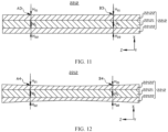
- the thickness of the support layer 22121 in any two positions in the width direction Z of the current collector, is greater than the total thickness of the conductive layers 22122 of the current collector 2212, and differences between the thicknesses of the support layer 22121 and the total thicknesses of the conductive layers 22122 of the current collector 2212 are equal.
- the thickness of the support layer 22121 at position A3, is greater than the total thickness of the conductive layers 22122 of the current collector 2212, and at position B3, the thickness of the support layer 22121 is greater than the total thickness of the conductive layers 22122 of the current collector 2212.
- the difference between the thickness of the support layer 22121 at position A3 and the total thickness of the conductive layers 22122 of the current collector 2212 at position A3 equals the difference between the thickness of the support layer 22121 at position B3 and the total thickness of the conductive layers 22122 of the current collector 2212 at position B3.
- the conductive layer 22122 is disposed on each of two sides of the support layer 22121.
- the support layer 22121 is of a uniformly thick structure, and the conductive layers 22122 on two sides of the support layer 22121 are both of a uniformly thick structure.
- the thickness of the support layer 22121 in any two positions in the width direction Z of the current collector, is greater than the total thickness of the conductive layers 22122 of the current collector 2212, and differences between the thicknesses of the support layer 22121 and the total thicknesses of the conductive layers 22122 of the current collector 2212 may be different.
- the thickness of the support layer 22121 at position A4, is greater than the total thickness of the conductive layers 22122 of the current collector 2212, and at position B4, the thickness of the support layer 22121 is greater than the total thickness of the conductive layers 22122 of the current collector 2212.
- the difference between the thickness of the support layer 22121 at position A4 and the total thickness of the conductive layers 22122 of the current collector 2212 at position A4 may be different from the difference between the thickness of the support layer 22121 at position B4 and the total thickness of the conductive layers 22122 of the current collector 2212 at position B4.
- an active substance layer 2211 may be disposed on a side of the conductive layer 22122 back away from the support layer 22121.
- the active substance layer 2211 can be disposed on each of two sides of the current collector 2212, which helps increase the energy density of the battery cell 20 including the current collector 2212.
- the embodiments of this application further provide an electrode plate 221.
- the electrode plate 221 includes an active substance layer and the current collector 2212 provided in any one of the foregoing embodiments.
- the active substance layer 2211 is disposed on a side of the conductive layer 22122 back away from the support layer 22121.
- the active substance layer 2211 may be applied to the surface of the conductive layer 22122 back away from the support layer 22121.
- the active substance layer 2211 may be uniformly applied to the surfaces of the conductive layers 22122, on two sides, back away from the support layer 22121, or may be uniformly applied to the surface of only one conductive layer 22122 back away from the support layer 22121.
- the material of the active substance layer 2211 varies with the polarity of the electrode plate 221.
- the active substance layer 2211 may be made of lithium cobalt oxide, lithium iron phosphate, lithium ternary, lithium manganese oxide, or the like. If the electrode plate 221 is a negative electrode plate, the active substance layer 2211 may be made of carbon, silicon, or the like.
- the insulating layer of the current collector 2212 provided in any one of the foregoing embodiments has good extensibility, allowing the current collector 2212 provided in any one of the foregoing embodiments of the first aspect to withstand a large swelling force, such that an electrode plate 221 including the current collector 2212 can withstand a large swelling force and the electrode plate 221 can meet the requirement on swelling alleviation of a battery cell 20 with high energy density, thereby improving the reliability of the battery cell 20, with high energy density, manufactured using the electrode plate 221.
- the embodiments of this application further provide an electrode assembly 22, where the electrode assembly 22 includes the electrode plate 221 provided in any one of the foregoing embodiments.
- the electrode assembly 22 includes two electrode plates 221 with opposite polarities, and the electrode plate 221 provided in any one of the foregoing embodiments may serve as a positive electrode plate of the electrode assembly 22 or a negative electrode plate. Alternatively, the two electrode plates 221 with opposite polarities may both be the electrode plate 221 provided in any one of the foregoing embodiments.
- the electrode plate 221 can withstand a large swelling force, and the electrode assembly 22 including the electrode plate 221 can also withstand the large swelling force, which is beneficial for the electrode assembly 22 to meet the requirement on swelling alleviation of the battery cell 20 with high energy density.
- the electrode assembly 22 includes two electrode plates 221 provided in any one of the foregoing embodiments, the two electrode plates 221 with opposite polarities.
- the positive electrode plate and negative electrode plate of the electrode assembly 22 are both the electrode plate 221 provided in any one of the foregoing embodiments, and each electrode plate 221 of the electrode assembly 22 can withstand a large swelling force, such that the electrode assembly 22 can meet the requirement on swelling alleviation of the battery cell 20 with high energy density.
- the electrode assembly 22 is a wound electrode assembly 22.
- the wound electrode assembly 22 is a structure formed by stacking and winding a separator and two electrode plates 221 with opposite polarities.
- the wound electrode assembly 22 may be in many shapes of, for example, a cylinder or square.
- the wound electrode assembly 22 withstands a large swelling force.
- the electrode plate 221 of the electrode assembly 22 is made using the current collector 2212 provided in the foregoing embodiment, and thus can beat a large swelling force, meet the requirement on swelling alleviation in the environment where the wound electrode assembly 22 is located, and reduce the risk of breaking the electrode plate 221 of the wound electrode assembly 22, improving the reliability of the battery cell 20 including the wound electrode assembly 22.
- the embodiments of this application further provide a battery cell 20, where the battery cell 20 includes the electrode assembly 22 provided in any one of the foregoing embodiments.
- At least one electrode plate 221 of the electrode assembly 22 provided in any one of the foregoing embodiments can withstand a large swelling force, and therefore the battery cell 20 including the electrode assembly 22 has a low risk of short circuit due to the breaking of the electrode plate 221, which helps improve the reliability of the battery cell 20.
- the battery cell 20 is of a cylindrical structure.
- the housing 21 of the battery cell 20 and the electrode assembly 22 are both of a cylindrical structure.
- the battery cell 20 being a lithium-ion battery cell 100 is used as an example.
- the active substance layer 2211 of the negative electrode plate has evolved from graphite (C) to silicon/graphite (Si/C), and as the silicon content continuously increases, the volume swelling rate of the battery cell 20 continuously increases.
- the housing 21 with a cylindrical structure has a limited internal space for use, and thus during charging of the battery cell 20, the electrode plate 221 has a limited swelling space.
- the electrode plate 221 After the silicon/graphite (Si/C) battery cell 20 with high energy density is charged, the electrode plate 221 withstands a large swelling force and is likely to be damaged and broken, piercing the separator to abut against the adjacent electrode plate 221. This is likely to cause short circuit and thermal runaway of the lithium-ion battery 100.
- the electrode plate 221 of the electrode assembly 22 of the battery cell 20 with a cylindrical structure can withstand a large swelling force, such that the battery cell 20 with a cylindrical structure has a low risk of short circuit due to the breaking of the electrode plate 221, which helps improve the reliability of the battery cell 20 with a cylindrical structure.
- the embodiments of this application further provide a battery 100, where the battery 100 includes the battery cell 20 provided in any one of the foregoing embodiments.
- the battery cell 20 provided in any one of the embodiments has good reliability, and the battery 100 including the battery cell 20 also has good reliability.
- the embodiments of this application further provide an electric device, including the battery 100 provided in any one of the foregoing embodiments.
- the battery 100 provided in the foregoing embodiment has good reliability, and an electric device to which the battery 100 provides electrical energy has good reliability of electricity supply.
- the embodiments of this application provide a battery cell 20 with a cylindrical structure.
- the battery cell 20 includes a housing 21 of a cylindrical structure and an electrode assembly 22 of a cylindrical structure.
- the electrode assembly 22 includes two electrode plates 221 with opposite polarities, and the electrode plate 221 includes a current collector 2212 and an active substance layer 2211.
- the current collector 2212 includes a support layer 22121 and two conductive layers 22122. In the thickness direction X of the current collector, the two conductive layers 22122 are respectively disposed on two sides of the support layer 22121. The elongation of the support layer 22121 is greater than the elongation of conductive layer 22122.
- the thickness of the support layer 22121 is greater than the total thickness of the conductive layers 22122 of the current collector 2212.
- the support layer 22121 is an insulating layer, and the surface of each conductive layer 22122 back away from the support layer 22121 is coated with the active substance layer 2211.
Landscapes
- Chemical & Material Sciences (AREA)
- Engineering & Computer Science (AREA)
- Chemical Kinetics & Catalysis (AREA)
- Electrochemistry (AREA)
- General Chemical & Material Sciences (AREA)
- Materials Engineering (AREA)
- Manufacturing & Machinery (AREA)
- Composite Materials (AREA)
- Secondary Cells (AREA)
- Battery Electrode And Active Subsutance (AREA)
- Cell Electrode Carriers And Collectors (AREA)
Abstract
Description
- This application claims priority to
Chinese Patent Application No. 202310507707.0, filed on May 08, 2023 - This application relates to the field of battery technologies, and specifically to a battery cell, a battery, and an electric device.
- Batteries are widely used in various fields such as portable electronic devices, electric vehicles, electric tools, drones, and energy storage devices. As the application fields expand, the reliability of batteries has become one of the key concerns for users.
- Embodiments of this application provide a battery cell, a battery, an electric device, to improve reliability of battery cells.
- According to a first aspect, an embodiment of this application provides a battery cell, where the battery cell is of a cylindrical structure, the battery cell includes an electrode assembly, the electrode assembly is of a wound structure, the electrode assembly includes an electrode plate, and the electrode plate includes a support layer and a conductive layer. In a thickness direction of a current collector, the conductive layer is disposed on at least one side of the support layer. Elongation of the support layer is greater than elongation of the conductive layer, and in the thickness direction of the current collector, the support layer has a thickness greater than a total thickness of the conductive layer of the current collector.
- In the foregoing technical solution, as the elongation of the support layer is greater than that of the conductive layer and the thickness of the support layer of the current collector is greater than the total thickness of the conductive layer of the current collector, under the condition that a thickness of the current collector is given, the thickness proportion of the support layer is greater than the thickness proportion of the conductive layer, allowing for good extensibility of the insulating layer, such that the current collector can withstand a large swelling force without breaking. This allows the current collector to meet the requirement on swelling alleviation of a battery cell with high-energy density, improving the reliability of the battery cell with high-energy density.
- In some embodiments of the first aspect of this application, in the thickness direction of the current collector, the thickness of the support layer is H1, and the total thickness of the conductive layer of the current collector is H2, H1 and H2 satisfying H1/H2≤50.
- In the foregoing technical solution, a larger thickness H1 of the support layer indicates better strength and elongation of the current collector. A larger total thickness H2 of the conductive layer indicates a better current flow capability. Under the condition that a thickness of the current collector is given, if H1/H2>50, a proportion of the thickness of the support layer in the thickness of the current collector is high, and a proportion of the total thickness of the conductive layer in the thickness of the current collector is low, which may result in a small current flow capability of the conductive layer. Therefore, H1/H2≤50 can not only allow for good strength and elongation of the current collector, to meet the requirement on swelling alleviation of a battery cell with high-energy density, but also allow for a good current flow capability of the conductive layer, to meet the charge and discharge requirement of the battery cell with high rate.
- In some embodiments of the first aspect of this application, 2≤H1/H2≤20.
- In the foregoing technical solution, if 1<H1/H2<2, the thickness of the support layer is a slightly larger than the total thickness of the conductive layer, and a battery cell manufactured using such current collector is difficult to meet the requirements of both a high energy density and a high rate. If 20<H1/H2<50, the thickness of the support layer is greatly larger than the total thickness of the conductive layer. This may result in, under the condition that the thickness of the current collector is given, a small total thickness of the conductive layer, thereby causing a low current flow capability of the conductive layer. Therefore, 2≤H1/H2≤20 allows the current collector to have good strength and elongation of and the conductive layer of the current collector to have a good current flow capability. The battery cell manufactured using such current collector can meet the requirements of both a high energy density and a high rate.
- In some embodiments of the first aspect of this application, in the thickness direction of the current collector, the thickness of the support layer is H1, satisfying 1µm≤H1≤20µm.
- In the foregoing technical solution, if 1µm>H1, the strength and elongation of the support layer are both low, causing the current collector to have low strength and elongation. If H1>20µm, the support layer has a large thickness, causing the current collector to have a large thickness and occupy a large space, and decreasing the energy density of the battery cell manufactured using the current collector. Therefore, 1µm≤H1<20µm allows the current collector to have good strength and elongation to meet the requirement on swelling alleviation of a battery cell with high energy density.
- In some embodiments of the first aspect of this application, 3µm≤H1≤14µm.
- In the foregoing technical solution, in the case of 3µm≤H1≤14µm, the strength and elongation of the support layer are both good, such that the current collector has good strength and elongation to meet the requirement on swelling alleviation of a battery cell with high energy density.
- In some embodiments of the first aspect of this application, the total thickness of the conductive layer of the current collector is H2, satisfying 0.1µm ≤H2≤10µm.
- In the foregoing technical solution, if 0.1µm>H2, the current flow capability of the conductive layer is weak. If H1>10µm, the conductive layer has a large thickness and occupies a large space, which may decrease the energy density of the battery cell manufactured using the current collector. Therefore, 0.1µm≤H1≤10µm allows the conductive layer of the current collector to have good electrical conductivity to meet the high rate requirement of the battery cell.
- In some embodiments of the first aspect of this application, 0.5µm≤H2≤5µm.
- In the foregoing technical solution, 0.5µm≤H1≤5µm allows the conductive layer of the current collector to have better electrical conductivity to meet the high rate requirement of the battery cell.
- In some embodiments of the first aspect of this application, a surface of the conductive layer facing the support layer is provided with a protrusion, the protrusion being inserted in the support layer.
- In the foregoing technical solution, the protrusion disposed on the surface of the conductive layer facing the support layer is inserted in the support layer, which can increase the connection area between the conductive layer and the support layer and helps improve the connection stability between the conductive layer and the support layer. The protrusion disposed on the surface of the conductive layer facing the support layer is inserted in the support layer, which can enhance the connection force between the conductive layer and the support layer. During swelling of the current collector, the connection force can restrain swelling of the conductive layer and support layer, which helps alleviate swelling of the current collector and increase elongation of the current collector. In this way, the current collector can meet the requirement on swelling alleviation of a battery cell with high energy density, thereby improving the reliability of the battery cell with high energy density.
- In some embodiments of the first aspect of this application, the support layer is an insulating layer.
- In the foregoing technical solution, the support layer being an insulating layer can reduce the weight of the current collector, thereby reducing the weight of the battery cell manufactured using the current collector.
- In some embodiments of the first aspect of this application, a material of the insulating layer includes at least one of polypropylene, polyethylene, and polyethylene terephthalate.
- In the foregoing technical solution, polypropylene, polyethylene, and polyethylene terephthalate have good insulation properties and heat resistance, and thus it is reliable to use a battery cell manufactured using such current collector. Polypropylene, polyethylene, and polyethylene terephthalate are relatively light, which helps reduce the weight of the current collector, thereby reducing the weight of the battery cell manufactured using such current collector.
- In some embodiments of the first aspect of this application, the conductive layer is made of copper or aluminum.
- In the foregoing technical solution, copper or aluminum has good electrical conductivity, which helps improve the reliability of a battery cell manufactured using the current collector.
- In some embodiments of the first aspect of this application, in the thickness direction of the current collector, the conductive layer is disposed on each of two sides of the support layer.
- In the foregoing technical solution, as the conductive layer is disposed on each of two sides of the support layer, in the thickness direction of the current collector, an active substance layer can be disposed on each of two sides of the current collector, which helps increase the energy density of a battery cell including the current collector.
- In some embodiments of the first aspect of this application, the electrode plate includes an active substance layer, and in the thickness direction of the current collector, the active substance layer is disposed on a side of the conductive layer back away from the support layer.
- In the foregoing technical solution, the insulating layer of the current collector has good extensibility, allowing the current collector to withstand a large swelling force, such that an electrode plate including the current collector can withstand a large swelling force and the electrode plate can meet the requirement on swelling alleviation of a battery cell with high energy density, which can improve the reliability of the battery cell having high energy density and manufactured using the electrode plate.
- In some embodiments of the first aspect of this application, the electrode assembly includes such two electrode plates with opposite polarities.
- According to a second aspect, an embodiment of this application further provides a battery including the battery cell provided in any one of the embodiments of the first aspect.
- In the foregoing technical solution, the battery cell provided in any one of the embodiments of the second aspect has good reliability, and a battery including the battery cell also has good reliability.
- According to a third aspect, an embodiment of this application further provides an electric device including the battery provided in the embodiments of the first aspect.
- In the foregoing technical solution, the battery provided in the embodiments of a fifth aspect has good reliability, and an electric device to which the battery provides electrical energy has good reliability of electricity supply.
- In order to describe the technical solutions in the embodiments of this application more clearly, the following briefly describes the accompanying drawings required for describing the embodiments. It should be appreciated that, the accompanying drawings below only show some embodiments of this application, and thus should not be considered as a limitation to the scope. A person of ordinary skill in the art may still derive other related drawings from the accompanying drawings without creative efforts.
-
FIG. 1 is a schematic structural diagram of a vehicle according to some embodiments of this application; -
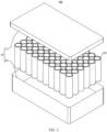
FIG. 2 is an exploded view of a battery according to some embodiments of this application; -
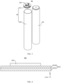
FIG. 3 is an exploded view of a battery cell according to some embodiments of this application; -
FIG. 4 is a schematic structural diagram of an electrode plate according to some embodiments of this application; -
FIG. 5 is a schematic structural diagram of a current collector according to some embodiments of this application; -
FIG. 6 is a comparison diagram of a support layer before and after tension fracture; -
FIG. 7 is a comparison diagram of a conductive layer before and after tension fracture; -
FIG. 8 is a schematic structural diagram of a current collector according to some other embodiments of this application; -
FIG. 9 is a schematic structural diagram of a current collector according to still some other embodiments of this application; -
FIG. 10 is a schematic structural diagram of an electrode plate according to some other embodiments of this application; -
FIG. 11 is a schematic structural diagram of a current collector according to yet some other embodiments of this application; and -
FIG. 12 is a schematic structural diagram of a current collector according to still yet some other embodiments of this application. - Reference numerals in the accompanying drawings are described as follows: 1000. vehicle; 100. battery; 10. box; 11. first portion; 12. second portion; 20. battery cell; 21. housing; 211. end cover; 212. housing body; 213. electrode terminal; 22. electrode assembly; 221. electrode plate; 2211. active substance layer; 2212. current collector; 22121. support layer; 221211. first sub-portion; 221212. second sub-portion; 22122. conductive layer; 221221. third sub-portion; 221222. fourth sub-portion; 22123. protrusion; 22124. recess; 200. controller; 300. motor; X. thickness direction of current collector; Y length direction of current collector; and Z. width direction of current collector.
- To make the objectives, technical solutions, and advantages of the embodiments of this application clearer, the following clearly and completely describes the technical solutions in the embodiments of this application with reference to the accompanying drawings in the embodiments of this application. Apparently, the described embodiments are some but not all of the embodiments of this application. Generally, the components of the embodiments of this application as described and illustrated in the accompanying drawings herein can be arranged and designed in a variety of configurations.
- Therefore, the following detailed description of the embodiments of this application as provided in the accompanying drawings is not intended to limit the scope of this application but merely to represent selected embodiments of this application. All other embodiments obtained by persons of ordinary skill in the art based on the embodiments of this application without creative efforts shall fall within the protection scope of this application.
- It should be noted that, without conflict, the embodiments and features in the embodiments in this application may be combined with each other.
- It should be noted that similar reference signs and letters indicate similar items in the following drawings, and therefore once an item is defined in one drawing, it does not need to be further defined and explained in the subsequent drawings.
- In the description of the embodiments of this application, it should be noted that the orientations or positional relationships as indicated are orientations or positional relationships based on the accompanying drawings, or conventional orientations or positional relationships of products of this application, or orientations or positional relationships as conventionally understood by persons skilled in the art, and the orientations or positional relationships as indicated are merely for ease and brevity of description of this application rather than indicating or implying that the apparatuses or elements mentioned must have specific orientations or must be constructed or manipulated according to specific orientations, and therefore cannot be understood as limitations on this application. In addition, the terms "first", "second", "third", and the like are merely intended for distinguishing purposes and shall not be understood as any indication or implication of relative importance.
- Currently, from a perspective of the market development, application of traction batteries is being more extensive. Traction batteries have been not only used in energy storage power supply systems such as hydroelectric power plants, thermal power plants, wind power plants, and solar power plants, but also widely used in many other fields including electric transportation tools such as electric bicycles, electric motorcycles, and electric vehicles, military equipment, and aerospace. With the continuous expansion of application fields of traction batteries, market demands for traction batteries are also increasing.
- The battery mentioned in the embodiments of this application is a single physical module that includes one or more battery cells for providing a higher voltage and capacity. For example, the battery mentioned in this application may include a battery module, a battery pack, or the like. A battery typically includes a box configured to enclose one or more battery cells. The box can prevent liquids or other foreign matter from affecting charging or discharging of the battery cell.
- In this application, the battery cell may include a lithium-ion secondary battery, a lithium-ion primary battery, a lithium-sulfur battery, a sodium-lithium-ion battery, a sodium-ion battery, a magnesium-ion battery, or the like. This is not limited in the embodiments of this application. The battery cell may be cylindrical, flat, cuboid, or of other shapes, which is not limited in the embodiments of this application either. The battery cell is typically divided into three types by packaging method: cylindrical battery cell, prismatic battery cell, and pouch battery cell. This is not limited in the embodiments of this application either.
- The battery cell includes a housing and an electrode assembly, where the electrode assembly is accommodated in the housing. The electrode assembly includes a separator and two electrode plates with opposite polarities. The two electrode plates with opposite polarities are positive electrode plate and negative electrode plate. The battery cell mainly relies on movement of metal ions between a positive electrode plate and a negative electrode plate to work. The electrode plate includes a current collector and an active substance layer, where the active substance layer is applied to a surface of the current collector.
- For a cylindrical battery cell, as the energy density of the battery cell increases, during cycling of the cylindrical battery cell, the volume swelling rate of the battery cell continuously increases, but the housing of the battery cell has a limited internal space, that is, a large group margin, resulting in a small gap between the positive electrode plate and negative electrode plate and a limited swelling space of the electrode plate during charging of the battery cell. In this case, one electrode plate withstands a large swelling force after the battery cell of high energy density is charged, and is likely to be damaged and broken, and the broken electrode plate pierces the separator to abut against the adjacent electrode plate, which is prone to short circuit and leads to thermal runaway of the battery cell. In other words, the electrode plate cannot withstand a large swelling force and breaks, which results in low reliability of the battery cell.
- Based on the foregoing consideration, to alleviate the problem of low reliability of the cylindrical battery cell due to the breakage of the electrode plate under a large swelling force that cannot be withstood by the electrode plate, an embodiment of this application provides a battery cell. The battery cell is of a cylindrical structure, and the battery cell includes an electrode assembly. The electrode assembly includes an electrode plate, the electrode plate includes a current collector, and the current collector includes a support layer and a conductive layer. In a thickness direction of the current collector, the conductive layer is disposed on at least one side of the support layer, elongation of the support layer is greater than elongation of the conductive layer, and the support layer has a thickness greater than a total thickness of the conductive layer of the current collector.
- As the elongation of the support layer is greater than that of the conductive layer and the thickness of the support layer of the current collector is greater than the total thickness of the conductive layer of the current collector, under the condition that a thickness of the current collector is given, the thickness proportion of the support layer is greater than the total thickness proportion of the conductive layer, allowing for good extensibility of the insulating layer, such that the current collector can withstand a large swelling force without breaking. This allows the current collector to meet the requirement on swelling alleviation of the battery cell with high-energy density, improving the reliability of the battery cell with high-energy density.
- The current collector disclosed by the embodiments of this application can be used for manufacturing an electrode plate and a battery cell. The battery cell including the electrode plate provided in the embodiments of this application may be used without limitation in electric devices such as vehicles, ships, or aircrafts. A battery cell, battery, or the like manufactured using the electrode plate disclosed in this application may be used to form a power system of the electric device. This is conducive to alleviating the problem that the electrode plate cannot withstand a large swelling force without breaking, or will be broken, thereby improving the reliability of the battery.
- The embodiments of this application provide an electric device that uses a battery as the power supply. The electric device may be, but is not limited to, a mobile phone, a tablet, a laptop computer, an electric toy, an electric bicycle, an electric vehicle, a ship, or a spacecraft. The electric toy may be a fixed or mobile electric toy, for example, a game console, an electric toy car, an electric toy ship, and an electric toy airplane. The spacecraft may include an airplane, a rocket, a space shuttle, a spaceship, and the like.
- Referring to
FIG. 1, FIG. 1 is a schematic structural diagram of avehicle 1000 according to some embodiments of this application. Thevehicle 1000 may be a fossil fuel vehicle, a natural-gas vehicle, or a new energy vehicle, where the new energy vehicle may be a battery electric vehicle, a hybrid electric vehicle, a range-extended vehicle, or the like. Thevehicle 1000 is provided with abattery 100 inside, where thebattery 100 may be disposed at the bottom, front or rear of thevehicle 1000. Thebattery 100 may be configured to supply power to thevehicle 1000. For example, thebattery 100 may be used as an operational power source for thevehicle 1000. Thevehicle 1000 may further include acontroller 200 and amotor 300, where thecontroller 200 is configured to control thebattery 100 to supply power to themotor 300, for example, to satisfy power needs of start, navigation, and driving of thevehicle 1000. - In some embodiments of this application, the
battery 100 can be used as not only the operational power source for thevehicle 1000 but also a driving power source for thevehicle 1000, replacing or partially replacing fossil fuel or natural gas to provide driving traction for thevehicle 1000. - Referring to
FIG. 2, FIG. 2 is an exploded view of abattery 100 according to some embodiments of this application. Thebattery 100 includes abox 10 and abattery cell 20, where thebattery cell 20 is accommodated in thebox 10. Thebox 10 is configured to provide an accommodating space for thebattery cell 20. Thebox 10 may be a variety of structures. In some embodiments, thebox 10 may include a first portion 11 and asecond portion 12. The first portion 11 and thesecond portion 12 fit together so that the first portion 11 and thesecond portion 12 jointly define a space for accommodating thebattery cell 20. Thesecond portion 12 may be a hollow structure with one end open, and the first portion 11 may be a plate structure, where the first portion 11 covers the open side of thesecond portion 12 for the first portion 11 and thesecond portion 12 to jointly define an accommodating space; alternatively, the first portion 11 and thesecond portion 12 may both be hollow structures with one side open, where the open side of the first portion 11 is engaged with the open side of thesecond portion 12. Certainly, thebox 10 formed by the first portion 11 and thesecond portion 12 may have a variety of shapes, for example, cylinder or cuboid. - In the
battery 100, thebattery cells 20 may be present in plurality, and the plurality ofbattery cells 20 may be connected in series, parallel, or series-parallel, where being connected in series-parallel means a combination of series and parallel connections of the plurality ofbattery cells 20. The plurality ofbattery cells 20 may be directly connected in series, parallel or series-parallel, and then an entirety of the plurality ofbattery cells 20 is accommodated in thebox 10; or certainly, thebattery 100 may be formed by a plurality ofbattery cells 20 being connected in series, parallel or series-parallel first to form a battery module and then a plurality of battery modules being connected in series, parallel or series-parallel to form an entirety which is accommodated in thebox 10. Thebattery 100 may further include other structures. For example, thebattery 100 may further include a busbar configured to implement electrical connection between the plurality ofbattery cells 20. - Each
battery cell 20 may be a secondary battery or a primary battery, and may be a lithium-sulfur battery, a sodium-ion battery, or a magnesium-ion battery, without being limited thereto. Thebattery cell 20 may be cylindrical, flat, cuboid, or of other shapes. - Referring to
FIG. 3, FIG. 3 is a schematic structural exploded view of abattery cell 20 according to some embodiments of this application. Thebattery cell 20 refers to a smallest element constituting thebattery 100. As shown inFIG. 3 , thebattery cell 20 includes a housing 21, anelectrode assembly 22, and other functional components. Theelectrode assembly 22 is accommodated in the housing 21. - The housing 21 includes an
end cover 211 and ahousing body 212. Theend cover 211 refers to a component that covers an opening of thehousing body 212 to isolate an internal environment of thebattery cell 20 from an external environment. A shape of theend cover 211 is not limited and may be adapted to a shape of thehousing body 212 to fit thehousing body 212. Optionally, theend cover 211 may be made of a material (for example, aluminum alloy) with specified hardness and strength, so that theend cover 211 is less likely to deform when subjected to extrusion and collision, allowing thebattery cell 20 to have higher structural strength and enhanced reliability. Theend cover 211 may be provided with functional components such as anelectrode terminal 213. Theelectrode terminal 213 may be configured to be electrically connected to theelectrode assembly 22 for outputting or inputting electrical energy of thebattery cell 20. In some embodiments, theend cover 211 may further be provided with a pressure relief mechanism for releasing internal pressure when the internal pressure or a temperature of thebattery cell 20 reaches a threshold. Theend cover 211 may also be made of various materials, such as copper, iron, aluminum, stainless steel, aluminum alloy, and plastic, which are not particularly limited in the embodiments of this application. In some embodiments, an insulator may also be provided on an inner side of theend cover 211. The insulator may be configured to isolate an electrically connected component in thehousing body 212 from theend cover 211 to reduce a risk of short circuit. For example, the insulator may be made of plastic, rubber, or the like. - The
housing body 212 is an assembly configured to form an internal environment of thebattery cell 20 together with theend cover 211, where the formed internal environment may be configured to accommodate theelectrode assembly 22, an electrolyte, and other components. Thehousing body 212 and theend cover 211 may be separate components, an opening may be provided on thehousing body 212, and theend cover 211 covers the opening to form the internal environment of thebattery cell 20. Theend cover 211 and thehousing body 212 are not limited and may also be integrated. Specifically, theend cover 211 and thehousing body 212 may form a shared connection surface before other components are disposed inside the housing, and then thehousing body 212 is covered with theend cover 211 when inside of thehousing body 212 needs to be enclosed. Thehousing body 212 may be of various shapes and sizes, such as a cuboid shape, a cylindrical shape, and a hexagonal prism shape. Specifically, a shape of thehousing body 212 may be determined according to a specific shape and size of theelectrode assembly 22. Thehousing body 212 may be made of various materials, such as copper, iron, aluminum, stainless steel, aluminum alloy, and plastic, which are not particularly limited in the embodiments of this application. - The
electrode assembly 22 is a component in which electrochemical reactions occur in thebattery cell 20. Thehousing body 212 may include one ormore electrode assemblies 22. Theelectrode assembly 22 is mainly formed by winding or stacking twoelectrode plates 221 with opposite polarities, and a separator is generally provided between the twoelectrode plates 221 with opposite polarities. The separator may be made of PP (polypropylene, polypropylene), PE (polyethylene, polyethylene), or the like. - Portions, of the two
electrode plates 221 with opposite polarities, having an active substance form the body portion of theelectrode assembly 22, and portions, of the twoelectrode plates 221 with opposite polarities, without the active substance respectively form tabs, namely, a positive electrode tab and a negative electrode tab. The positive electrode tab and the negative electrode tab may both be located at one end of the body portion or be located at two ends of the body portion respectively. During charging and discharging of thebattery 100, a positive electrode active substance and a negative electrode active substance react with an electrolyte, and the tabs are connected to theelectrode terminals 213 to form a current loop. - As shown in
FIG. 4 , in some embodiments, theelectrode plate 221 includes anactive substance layer 2211 and acurrent collector 2212. In the thickness direction X of the current collector, theactive substance layer 2211 is disposed at least one side of thecurrent collector 2212. - In the thickness direction X of the current collector, the
active substance layer 2211 may be disposed on only one side or on both sides of thecurrent collector 2212. - The material of the
active substance layer 2211 varies with the polarity of theelectrode plate 221. For example, when theelectrode plate 221 is a positive electrode plate, theactive substance layer 2211 may be made of lithium cobalt oxide, lithium iron phosphate, lithium ternary, lithium manganese oxide, or the like. If theelectrode plate 221 is a negative electrode plate, theactive substance layer 2211 may be made of carbon, silicon, or the like. - As shown in
FIGs. 4 and5 , in some embodiments, thecurrent collector 2212 includes asupport layer 22121 and aconductive layer 22122. In the thickness direction X of the current collector, theconductive layer 22122 is disposed on at least one side of thesupport layer 22121. The elongation of thesupport layer 22121 is greater than the elongation ofconductive layer 22122. In the thickness direction X of the current collector, the thickness of thesupport layer 22121 is greater than the total thickness of theconductive layer 22122 of thecurrent collector 2212. - In the thickness direction X of the current collector, the
conductive layer 22122 may be disposed on only one side or on both sides of thesupport layer 22121. - The
conductive layer 22122 may be adhered to the surface of thesupport layer 22121 in the thickness direction X of the current collector or may be disposed on a side of thesupport layer 22121 in the thickness direction X of the current collector in another manner of, for example, melting connection. The material of theconductive layer 22122 may vary with the polarity of theelectrode plate 221. If theelectrode plate 221 is a positive electrode plate, theconductive layer 22122 may be made of aluminium, and if theelectrode plate 221 is a negative electrode plate, theconductive layer 22122 may be made of copper. - As shown in
FIG. 6 , in the length direction Y of the current collector, thesupport layer 22121 has an original length of L0 before tension applied, and has a total length of L'0 after breakage under tension applied, where the length difference before and after tension applied expressed as: ΔL=L'0-L0, and elongation at break δ1 of thesupport layer 22121 is expressed as: δ1=(L'0-L0)/L*100%. It should be noted that after elongated, thesupport layer 22121 is broken into afirst sub-portion 221211 and asecond sub-portion 221212 in the length direction Y of the current collector. In the length direction Y of the current collector, thefirst sub-portion 221211 has a length of L'01, and thesecond sub-portion 221212 has a length of L'02, where L'0=L'01+L'02. - As shown in
FIG. 7 , in the length direction Y of the current collector, theconductive layer 22122 has the original length of H0 before tension applied, and has a total length of H'0 after breakage under tension applied, where the length difference before and after tension applied is expressed as: ΔH=H'0-H0, and elongation at break δ2 of theconductive layer 22122 is expressed as: δ2=(H'0-H0)/H0*100%. The following relation is satisfied: δ1>δ2. It should be noted that after tension applied, theconductive layer 22122 is broken into athird sub-portion 221221 and afourth sub-portion 221222 in the length direction Y of the current collector. In the length direction Y of the current collector, thethird sub-portion 221221 has a length of H'01, and thefourth sub-portion 221222 has a length of H'02, where H'0=H'01+H'02. - Certainly, if in the width direction Z of the current collector, the sizes of the
support layer 22121 and theconductive layer 22122 suffice, thesupport layer 22121 and theconductive layer 22122 may further be subjected to the elongating test separately in the width direction Z of the current collector. The thickness direction X of the current collector, the length direction Y of the current collector, and the width direction Z of the current collector are perpendicular to each other. - The thickness of the
support layer 22121 refers to the size of thesupport layer 22121 in the thickness direction X of the current collector. Thesupport layer 22121 may be a uniformly thick structure or a non-uniformly thick structure. - The thickness of the
conductive layer 22122 refers to the size of theconductive layer 22122 in the thickness direction X of the current collector. Theconductive layer 22122 may be a uniformly thick structure or a non-uniformly thick structure. - In the thickness direction X of the current collector, in the embodiment in which the
conductive layer 22122 is disposed on only one side of thesupport layer 22121, the total thickness of theconductive layer 22122 of thecurrent collector 2212 is the thickness of theconductive layer 22122. As shown inFIG. 5 , in the thickness direction X of the current collector, a uniformly thickconductive layer 22122 is disposed on one side of thesupport layer 22121, theconductive layer 22122 has a thickness of H21, and the total thickness H2 of theconductive layer 22122 of thecurrent collector 2212 is equal to H21. - In the thickness direction X of the current collector, in the embodiment in which the
conductive layer 22122 is disposed on each of two sides of thesupport layer 22121, the total thickness of theconductive layers 22122 of thecurrent collector 2212 is a sum of the thicknesses of theconductive layers 22122 on two sides of thesupport layer 22121. As shown inFIGs. 11 and 12 , in the thickness direction X of the current collector, a uniformly thickconductive layer 22122 is disposed on each of two sides of thesupport layer 22121. Oneconductive layer 22122 has a thickness of H21, the other conductive layer has a thickness of H22, and a total thickness of theconductive layers 22122 of thecurrent collector 2212 is expressed with the following formula: H2=H21+H22, where H21 may equal H22 or not. - It should be noted that the thickness of the
support layer 22121 should be compared with the total thickness of theconductive layers 22122 of thecurrent collector 2212 in the same position in the width direction Z of the current collector. In the same position in the width direction Z of the current collector, the thickness of thesupport layer 22121 is greater than the total thickness of theconductive layers 22122 of thecurrent collector 2212. As shown inFIG. 5 , A1 and B1 are two different positions in the width direction Z of the current collector. For example, when the thickness of thesupport layer 22121 is compared with the total thickness of theconductive layers 22122 of thecurrent collector 2212, the thickness of thesupport layer 22121 at position A1 and the total thickness of the conductive layers of thecurrent collector 2212 at position A1 should be compared, or the thickness of thesupport layer 22121 at position B1 and the total thickness of the conductive layers of thecurrent collector 2212 at position B1 should be compared. - In an embodiment in which the
support layer 22121 is of a uniformly thick structure and eachconductive layer 22122 is of a uniformly thick structure, in different positions in the width direction Z of the current collector, the thickness of thesupport layer 22121 is greater than the total thickness of theconductive layers 22122 of thecurrent collector 2212, and the differences between the thicknesses of thesupport layer 22121 and the total thicknesses of theconductive layers 22122 of thecurrent collector 2212 are equal. For example, as shown inFIG. 5 , the difference of H2-H1 at position A1 equals the difference of H2-H1 at position B1. - In an embodiment in which the
support layer 22121 is of a non-uniformly thick structure, and eachconductive layer 22122 is of a non-uniformly thick structure, at different positions in the width direction Z of the current collector, the differences between the thicknesses of thesupport layer 22121 and the total thicknesses of theconductive layers 22122 of thecurrent collector 2212 may be equal or different. As shown inFIG. 8 , in the thickness direction X of the current collector, a non-uniformly thickconductive layer 22122 is disposed on a side of thesupport layer 22121. In the width direction Z of the current collector, the difference of H2-H1 at position A2 is different from the difference of H2-H1 at position B2. As shown inFIG. 8 , A2 and B2 are two different positions in the width direction Z of the current collector. For example, when the thickness of thesupport layer 22121 is compared with the total thickness of the conductive layer of thecurrent collector 2212, the thickness of thesupport layer 22121 at position A2 and the total thickness of theconductive layer 22122 of thecurrent collector 2212 at position A2 should be compared, or the thickness of thesupport layer 22121 at position B2 and the total thickness of theconductive layer 22122 of thecurrent collector 2212 at position B2 should be compared instead of comparing the thickness of thesupport layer 22121 at position A1 with the total thickness of theconductive layer 22122 at position B2. - As the elongation of the
support layer 22121 is greater than that of theconductive layer 22122 and the thickness of thesupport layer 22121 of thecurrent collector 2212 is greater than the total thickness of theconductive layer 22122 of thecurrent collector 2212, under the condition that a thickness of thecurrent collector 2212 is given, the thickness proportion of thesupport layer 22121 is greater than the thickness proportion of theconductive layer 22122, allowing for good extensibility of the insulating layer, such that thecurrent collector 2212 can withstand a large swelling force without breaking. This allows thecurrent collector 2212 to meet the requirement on swelling alleviation on thebattery cell 20 with high-energy density, improving the reliability of thebattery cell 20 with high-energy density. - As shown in
FIGs. 4 and5 , in some embodiments, in the thickness direction X of the current collector, thesupport layer 22121 has a thickness of H1, and theconductive layer 22122 of thecurrent collector 2212 has a total thickness of H2, H1 and H2 satisfying H1/H2≤50. - Because the thickness of the
support layer 22121 is greater than the total thickness of theconductive layer 22122, that is, H1>H2, H1/H2>1. - For example, H1/H2 may be 5, 10, 15, 20, 25, 30, 35, 40, 45, 50, or the like.
- Taking an example in which the
support layer 22121 is made of PET, theconductive layer 22122 is made of aluminium, theconductive layer 22122 is disposed on each of two sides of thesupport layer 22121, theconductive layers 22122 on two sides of thesupport layer 22121 have the same thickness, thecurrent collector 2212 has a thickness of H1+H2 being 8µm, differentcurrent collectors 2212 of H1/H2 are subjected to an elongating test, to obtain data in Table 1 as follows:Table 1 H1/H2 0.5 1 2 3 4 5 6 8 10 20 30 50 70 Elongation at break of current collector 2.3% 9.5% 30.5% 33.4% 36.7% 43.1% 42.8% 46.3% 44.8% 50.2% 45.2% 45.3% 50.3% - As shown in Table 1, when H1/H2 is 0.5, each
current collector 2212 has elongation of 2.3%, which is low and difficult to satisfy the requirement on swelling alleviation of thebattery cell 20 with high energy density. When H1/H2 is 2, 3, 4, 5, 6, 8, 10, 20, 30, 50, or 70, thecurrent collector 2212 has high elongation. However, when H1/H2 is 70, theconductive layer 22122 has a thickness of only about 0.055µm and a quite small current flow capability. - Therefore, a larger thickness H1 of the
support layer 22121 indicates better strength and elongation of thecurrent collector 2212. A larger total thickness H2 of theconductive layer 22122 indicates a better current flow capability. In the case of a certain thickness of thecurrent collector 2212, if H1/H2>50, a percentage of the thickness of thesupport layer 22121 in the thickness of thecurrent collector 2212 is high, and a percentage of the total thickness of theconductive layer 22122 in the thickness of thecurrent collector 2212 is low, which may result in a small current flow capability of theconductive layer 22122. Therefore, H1/H2≤50 can not only allow for better strength and elongation of thecurrent collector 2212, to meet the requirement on swelling alleviation of thebattery cell 20 with high-energy density, but also allow for a good current flow capability of theconductive layer 22122, to meet the charge and discharge requirements of thebattery cell 20 with high rate. - In some embodiments, 2≤H1/H2≤20.
- For example, H1/H2 may be 2, 4, 6, 8, 12, 14, 16, 18, 19, 20, or the like.
- Still referring to Table 1, when 1<H1/H2<2, the
current collector 2212 has elongation between 9.5% and 30.5%, which is higher than that when H1/H2≤1, but difficult to meet the requirement for a higher energy density of the battery cell on the market. Compared with H1/H2 of 30, 50, or 70, H1/H2 of 5, 6, 8, 10, or 20 does not show a significant increase in elongation and also results in an excessively large thickness of thesupport layer 22121 and a small thickness of theconductive layer 22122, impacting the current flow capability. - Therefore, if 1<H1/H2<2, the thickness of the
support layer 22121 is a slightly larger than the total thickness of theconductive layer 22122, and abattery cell 20 manufactured using suchcurrent collector 2212 is difficult to meet the requirements of both a high energy density and a high rate. If 20<H1/H2<50, the thickness of thesupport layer 22121 is greatly larger than the total thickness of theconductive layer 22122. This, in the case of a certain thickness of thecurrent collector 2212, may result in a small total thickness of theconductive layer 22122 and a low current flow capability of theconductive layer 22122, which are also difficult to meet the requirements of both a high energy density and a high rate. Therefore, 2≤H1/H2≤20 allows thecurrent collector 2212 to have good strength and elongation and theconductive layer 22122 of thecurrent collector 2212 to have a good current flow capability. Thebattery cell 20 manufactured using suchcurrent collector 2212 can meet the requirements of both a high energy density and a high rate. - In some embodiments, in the thickness direction X of the current collector, the thickness of the
support layer 22121 is H1, satisfying 1µm≤H1≤20µm. - For example, H1 may be 1µm, 3µm, 5µm, 6µm, 8µm, 10µm, 13µm, 15µm, 18µm, 20µm, or the like.
- If 1µm>H1, the strength and elongation of the
support layer 22121 are both low, resulting in low strength and elongation of thecurrent collector 2212. If H1>20µm, thesupport layer 22121 has a large thickness, causing thecurrent collector 2212 to have a large thickness and occupy a large space, which may decrease the energy density of thebattery cell 20 manufactured using thecurrent collector 2212. Therefore, 1µm≤H1≤20µm allows thecurrent collector 2212 to have good strength and elongation to meet the requirement on swelling alleviation of thebattery cell 20 with high energy density. - In some embodiments, 3µm≤H1≤14µm.
- For example, H1 may be 3µm, 4µm, 4.5µm, 7µm, 7.5µm, 9µm, 10.5µm, 11µm, 12µm, 14µm, or the like.
- In the case of 3µm≤H1≤14µm, the strength and elongation of the
support layer 22121 are both good, resulting in good strength and elongation of thecurrent collector 2212, to meet the requirement on swelling alleviation of thebattery cell 20 with high energy density. - In some embodiments, the total thickness of the
conductive layer 22122 of thecurrent collector 2212 is H2, satisfying 0.1µm≤H2≤10µm. - For example, H2 may be 0.1µm 0.5µm, 1µm, 2µm, 3µm, 5µm, 7µm, 9µm, 10µm, or the like.
- If 0.1µm>H2, the current flow capability of the
conductive layer 22122 is weak. If H1>10µm, theconductive layer 22122 has a large thickness, occupying a large space, which may decrease the energy density of thebattery cell 20 manufactured using thecurrent collector 2212. Therefore, 0.1µm ≤H1≤10µm allows theconductive layer 22122 of thecurrent collector 2212 to have good electrical conductivity to meet the high rate requirement of thebattery cell 20. - In some embodiments, 0.5µm≤H2≤5µm.
- For example, H2 may be 0.5µm, 0.8µm, 1.5µm, 1.8µm, 2.5µm, 2.8µm, 3.5µm, 3.8µm, 4µm, 4.5µm, 4.8µm, 5µm, or the like.
- 0.5µm≤H1≤5µm allows the
conductive layer 22122 of thecurrent collector 2212 to have better electrical conductivity to meet the high rate requirement of thebattery cell 20. - As shown in
FIG. 9 , in some embodiments, a surface of theconductive layer 22122 facing thesupport layer 22121 is provided with aprotrusion 22123, theprotrusion 22123 being inserted in thesupport layer 22121. - In the thickness direction X of the current collector, the surface of the
conductive layer 22122 facing thesupport layer 22121 may be provided with one ormore protrusions 22123. "A plurality of" means two or more. In an embodiment in which the surface of theconductive layer 22122 facing thesupport layer 22121 is provided with a plurality ofprotrusions 22123, and the plurality ofprotrusions 22123 are spaced apart. The plurality ofprotrusions 22123 may be spaced apart uniformly or non-uniformly on the surface of theconductive layer 22122 facing thesupport layer 22121. - The
protrusion 22123 is inserted in thesupport layer 22121, and the surface of thesupport layer 22121 facing theconductive layer 22122 is provided with arecess 22124 for the protrusion to insert. Therecess 22124 in thesupport layer 22121 may be formed before theprotrusion 22123 is inserted in thesupport layer 22121. In other words, before theconductive layer 22122 is disposed on thesupport layer 22121, the surface of thesupport layer 22121 is provided with arecess 22124 in the thickness direction X of the current collector. Therecess 22124 on thesupport layer 22121 may further be formed in the process of inserting theprotrusion 22123 in thesupport layer 22121. - The
protrusion 22123 may be in many shapes. For example, theprotrusion 22123 is of a cylindrical structure, a prismatic structure, or the like. Therecess 22124 may fit theprotrusion 22123 in shape, such that better fitting between theprotrusion 22123 and therecess 22124 improves the stability of connection between theconductive layer 22122 and thesupport layer 22121. For example, when theprotrusion 22123 is of a triangular pyramid structure, therecess 22124 may alternatively be of a triangular pyramid structure, and the outer peripheral surface of theprotrusion 22123 fits the inner wall of therecess 22124. When theprotrusion 22123 is of a conical structure, therecess 22124 may alternatively be of a conical structure, and the outer peripheral surface of theprotrusion 22123 fits the inner wall of therecess 22124. - The
protrusion 22123 disposed on the surface of theconductive layer 22122 facing thesupport layer 22121 is inserted in thesupport layer 22121, which can increase the connection area between theconductive layer 22122 and thesupport layer 22121 and helps improve the connection stability between theconductive layer 22122 and thesupport layer 22121. Theprotrusion 22123 disposed on the surface of theconductive layer 22122 facing thesupport layer 22121 is inserted in thesupport layer 22121, which can enhance the connection force between theconductive layer 22122 and thesupport layer 22121. During swelling of thecurrent collector 2212, the connection force can restrain swelling of theconductive layer 22122 andsupport layer 22121, which helps alleviate swelling of thecurrent collector 2212 and increase elongation of thecurrent collector 2212. In this way, thecurrent collector 2212 can meet the requirement on swelling alleviation of thebattery cell 20 with high energy density, thereby improving the reliability of thebattery cell 20 with high energy density. - In some embodiments, the
support layer 22121 is an insulating layer. - The
support layer 22121 being an insulating layer can reduce the short-circuit risk, of thebattery cell 20 including thecurrent collector 2212, due to the contact between another structure and theconductive layer 22122, thereby improving the reliability of thebattery cell 20. In an embodiment in which theconductive layer 22122 is disposed on each of two sides of thesupport layer 22121 in the thickness direction X of the current collector, the insulating layer can insulate and separate theconductive layers 22122 on two sides. - The
support layer 22121 can not only enhance the strength of thecurrent collector 2212, but also reduce the weight of thecurrent collector 2212, thereby reducing the weight of thebattery cell 20 manufactured using thecurrent collector 2212. - In some embodiments, a material of the insulating layer includes at least one of polypropylene, polyethylene, and polyethylene terephthalate.
- The insulating layer may be made of any one of polypropylene, polyethylene, and polyethylene terephthalate.
- The insulating layer may be jointly made of several of polypropylene, polyethylene, and polyethylene terephthalate. For example, the insulating layer may be made of polypropylene and polyethylene, the insulating layer may be made of polyethylene and polyethylene terephthalate, the insulating layer may be made of polypropylene and polyethylene terephthalate, or the insulating layer may be jointly made of polypropylene, polyethylene, and polyethylene terephthalate.
- Polypropylene, polyethylene, and polyethylene terephthalate have good insulation properties and heat resistance, and thus it is reliable to use the
battery cell 20 manufactured using thecurrent collector 2212. Polypropylene, polyethylene, and polyethylene terephthalate are relatively light, which helps reduce the weight of thecurrent collector 2212, thereby reducing the weight of thebattery cell 20 manufactured using thecurrent collector 2212. - In some other embodiments, the
support layer 22121 may further be a conductor or semiconductor made of a material different from that of theconductive layer 22122. - In some embodiments, the
conductive layer 22122 is made of copper or aluminum. - If the
current collector 2212 serves as acurrent collector 2212 of the positive electrode plate, theconductive layer 22122 may be made of aluminum. If thecurrent collector 2212 serves as acurrent collector 2212 of the negative electrode plate, theconductive layer 22122 may be made of aluminum. - Copper or aluminum has good electrical conductivity, which helps improve the reliability of a
battery cell 20 manufactured using thecurrent collector 2212. - As shown in
FIGs. 10 and11 , in some embodiments, in the thickness direction X of the current collector, theconductive layer 22122 is disposed on each of two sides of thesupport layer 22121. - The
current collector 2212 includes thesupport layer 22121 and twoconductive layers 22122. In the thickness direction X of the current collector, the twoconductive layers 22122 are respectively disposed on two sides of thesupport layer 22121. - Materials of the two
conductive layers 22122 may be the same or different. Thicknesses of the twoconductive layers 22122 may be the same or different. - The total thickness of the
conductive layers 22122 of thecurrent collector 2212 is a sum of the thicknesses of theconductive layers 22122 disposed on two sides of thesupport layer 22121. For example, as shown inFIG. 11 , in the thickness direction X of the current collector, theconductive layers 22122 are respectively disposed on two sides of thesupport layer 22121. Thesupport layer 22121 is of a uniformly thick structure, and theconductive layers 22122 on the two sides of thesupport layer 22121 are both of a uniformly thick structure. The thicknesses of the twoconductive layers 22122 are H21 and H22, where H2=H21+H22. InFIG. 11 , in any two positions in the width direction Z of the current collector, the thickness of thesupport layer 22121 is greater than the total thickness of theconductive layers 22122 of thecurrent collector 2212, and differences between the thicknesses of thesupport layer 22121 and the total thicknesses of theconductive layers 22122 of thecurrent collector 2212 are equal. For example, inFIG. 11 , at position A3, the thickness of thesupport layer 22121 is greater than the total thickness of theconductive layers 22122 of thecurrent collector 2212, and at position B3, the thickness of thesupport layer 22121 is greater than the total thickness of theconductive layers 22122 of thecurrent collector 2212. In addition, the difference between the thickness of thesupport layer 22121 at position A3 and the total thickness of theconductive layers 22122 of thecurrent collector 2212 at position A3 equals the difference between the thickness of thesupport layer 22121 at position B3 and the total thickness of theconductive layers 22122 of thecurrent collector 2212 at position B3. - As shown in
FIG. 12 , in the thickness direction X of the current collector, theconductive layer 22122 is disposed on each of two sides of thesupport layer 22121. Thesupport layer 22121 is of a uniformly thick structure, and theconductive layers 22122 on two sides of thesupport layer 22121 are both of a uniformly thick structure. The thicknesses of the twoconductive layers 22122 in the same position are respectively H21 and H22, and H2=H21+H22. InFIG. 12 , in any two positions in the width direction Z of the current collector, the thickness of thesupport layer 22121 is greater than the total thickness of theconductive layers 22122 of thecurrent collector 2212, and differences between the thicknesses of thesupport layer 22121 and the total thicknesses of theconductive layers 22122 of thecurrent collector 2212 may be different. For example, inFIG. 12 , at position A4, the thickness of thesupport layer 22121 is greater than the total thickness of theconductive layers 22122 of thecurrent collector 2212, and at position B4, the thickness of thesupport layer 22121 is greater than the total thickness of theconductive layers 22122 of thecurrent collector 2212. In addition, the difference between the thickness of thesupport layer 22121 at position A4 and the total thickness of theconductive layers 22122 of thecurrent collector 2212 at position A4 may be different from the difference between the thickness of thesupport layer 22121 at position B4 and the total thickness of theconductive layers 22122 of thecurrent collector 2212 at position B4. - In the thickness direction X of the current collector, an
active substance layer 2211 may be disposed on a side of theconductive layer 22122 back away from thesupport layer 22121. - As the
conductive layer 22122 is disposed on each of two sides of thesupport layer 22121, in the thickness direction X of the current collector, theactive substance layer 2211 can be disposed on each of two sides of thecurrent collector 2212, which helps increase the energy density of thebattery cell 20 including thecurrent collector 2212. - The embodiments of this application further provide an
electrode plate 221. Theelectrode plate 221 includes an active substance layer and thecurrent collector 2212 provided in any one of the foregoing embodiments. In the thickness direction X of the current collector, theactive substance layer 2211 is disposed on a side of theconductive layer 22122 back away from thesupport layer 22121. - The
active substance layer 2211 may be applied to the surface of theconductive layer 22122 back away from thesupport layer 22121. In an embodiment in which theconductive layer 22122 is disposed on each of two sides of the insulating layer of thecurrent collector 2212 in the thickness direction X of the current collector, theactive substance layer 2211 may be uniformly applied to the surfaces of theconductive layers 22122, on two sides, back away from thesupport layer 22121, or may be uniformly applied to the surface of only oneconductive layer 22122 back away from thesupport layer 22121. - The material of the
active substance layer 2211 varies with the polarity of theelectrode plate 221. For example, when theelectrode plate 221 is a positive electrode plate, theactive substance layer 2211 may be made of lithium cobalt oxide, lithium iron phosphate, lithium ternary, lithium manganese oxide, or the like. If theelectrode plate 221 is a negative electrode plate, theactive substance layer 2211 may be made of carbon, silicon, or the like. - The insulating layer of the
current collector 2212 provided in any one of the foregoing embodiments has good extensibility, allowing thecurrent collector 2212 provided in any one of the foregoing embodiments of the first aspect to withstand a large swelling force, such that anelectrode plate 221 including thecurrent collector 2212 can withstand a large swelling force and theelectrode plate 221 can meet the requirement on swelling alleviation of abattery cell 20 with high energy density, thereby improving the reliability of thebattery cell 20, with high energy density, manufactured using theelectrode plate 221. - The embodiments of this application further provide an
electrode assembly 22, where theelectrode assembly 22 includes theelectrode plate 221 provided in any one of the foregoing embodiments. - The
electrode assembly 22 includes twoelectrode plates 221 with opposite polarities, and theelectrode plate 221 provided in any one of the foregoing embodiments may serve as a positive electrode plate of theelectrode assembly 22 or a negative electrode plate. Alternatively, the twoelectrode plates 221 with opposite polarities may both be theelectrode plate 221 provided in any one of the foregoing embodiments. - Because the elongation of the
current collector 2212 of theelectrode plate 221 provided in any one of the foregoing embodiments is large, theelectrode plate 221 can withstand a large swelling force, and theelectrode assembly 22 including theelectrode plate 221 can also withstand the large swelling force, which is beneficial for theelectrode assembly 22 to meet the requirement on swelling alleviation of thebattery cell 20 with high energy density. - In some embodiments, the
electrode assembly 22 includes twoelectrode plates 221 provided in any one of the foregoing embodiments, the twoelectrode plates 221 with opposite polarities. - That is, the positive electrode plate and negative electrode plate of the
electrode assembly 22 are both theelectrode plate 221 provided in any one of the foregoing embodiments, and eachelectrode plate 221 of theelectrode assembly 22 can withstand a large swelling force, such that theelectrode assembly 22 can meet the requirement on swelling alleviation of thebattery cell 20 with high energy density. - In some embodiments, the
electrode assembly 22 is awound electrode assembly 22. - The
wound electrode assembly 22 is a structure formed by stacking and winding a separator and twoelectrode plates 221 with opposite polarities. Thewound electrode assembly 22 may be in many shapes of, for example, a cylinder or square. - During cycling of the
battery cell 20, thewound electrode assembly 22 withstands a large swelling force. Theelectrode plate 221 of theelectrode assembly 22 is made using thecurrent collector 2212 provided in the foregoing embodiment, and thus can beat a large swelling force, meet the requirement on swelling alleviation in the environment where thewound electrode assembly 22 is located, and reduce the risk of breaking theelectrode plate 221 of thewound electrode assembly 22, improving the reliability of thebattery cell 20 including thewound electrode assembly 22. - The embodiments of this application further provide a
battery cell 20, where thebattery cell 20 includes theelectrode assembly 22 provided in any one of the foregoing embodiments. - At least one
electrode plate 221 of theelectrode assembly 22 provided in any one of the foregoing embodiments can withstand a large swelling force, and therefore thebattery cell 20 including theelectrode assembly 22 has a low risk of short circuit due to the breaking of theelectrode plate 221, which helps improve the reliability of thebattery cell 20. - In some embodiments, the
battery cell 20 is of a cylindrical structure. - The housing 21 of the
battery cell 20 and theelectrode assembly 22 are both of a cylindrical structure. Thebattery cell 20 being a lithium-ion battery cell 100 is used as an example. As the energy density of the lithium-ion battery 100 continuously increases, theactive substance layer 2211 of the negative electrode plate has evolved from graphite (C) to silicon/graphite (Si/C), and as the silicon content continuously increases, the volume swelling rate of thebattery cell 20 continuously increases. The housing 21 with a cylindrical structure has a limited internal space for use, and thus during charging of thebattery cell 20, theelectrode plate 221 has a limited swelling space. After the silicon/graphite (Si/C)battery cell 20 with high energy density is charged, theelectrode plate 221 withstands a large swelling force and is likely to be damaged and broken, piercing the separator to abut against theadjacent electrode plate 221. This is likely to cause short circuit and thermal runaway of the lithium-ion battery 100. - The
electrode plate 221 of theelectrode assembly 22 of thebattery cell 20 with a cylindrical structure can withstand a large swelling force, such that thebattery cell 20 with a cylindrical structure has a low risk of short circuit due to the breaking of theelectrode plate 221, which helps improve the reliability of thebattery cell 20 with a cylindrical structure. - The embodiments of this application further provide a
battery 100, where thebattery 100 includes thebattery cell 20 provided in any one of the foregoing embodiments. - The
battery cell 20 provided in any one of the embodiments has good reliability, and thebattery 100 including thebattery cell 20 also has good reliability. - The embodiments of this application further provide an electric device, including the
battery 100 provided in any one of the foregoing embodiments. - The
battery 100 provided in the foregoing embodiment has good reliability, and an electric device to which thebattery 100 provides electrical energy has good reliability of electricity supply. - The embodiments of this application provide a
battery cell 20 with a cylindrical structure. Thebattery cell 20 includes a housing 21 of a cylindrical structure and anelectrode assembly 22 of a cylindrical structure. Theelectrode assembly 22 includes twoelectrode plates 221 with opposite polarities, and theelectrode plate 221 includes acurrent collector 2212 and anactive substance layer 2211. Thecurrent collector 2212 includes asupport layer 22121 and twoconductive layers 22122. In the thickness direction X of the current collector, the twoconductive layers 22122 are respectively disposed on two sides of thesupport layer 22121. The elongation of thesupport layer 22121 is greater than the elongation ofconductive layer 22122. In the thickness direction X of the current collector, the thickness of thesupport layer 22121 is greater than the total thickness of theconductive layers 22122 of thecurrent collector 2212. Thesupport layer 22121 is an insulating layer, and the surface of eachconductive layer 22122 back away from thesupport layer 22121 is coated with theactive substance layer 2211. - The foregoing descriptions are merely exemplary embodiments of this application, but are not intended to limit this application. Persons skilled in the art understand that this application may have various modifications and variations. Any modifications, equivalent replacements, and improvements made without departing from the spirit and principle of this application shall fall within the protection scope of this application.
Claims (16)
- A battery cell, wherein the battery cell is of a cylindrical structure, and the battery cell comprises:an electrode assembly, wherein the electrode assembly is of a wound structure, the electrode assembly comprises an electrode plate, the electrode plate comprises a current collector, the current collector comprises a support layer and a conductive layer, and in a thickness direction of the current collector, the conductive layer is disposed on at least one side of the support layer;wherein elongation of the support layer is greater than elongation of the conductive layer, and in the thickness direction of the current collector, the support layer has a thickness greater than a total thickness of the conductive layer of the current collector.
- The battery cell according to claim 1, wherein in the thickness direction of the current collector, the thickness of the support layer is H1, and the total thickness of the conductive layer of the current collector is H2, H1 and H2 satisfying H1/H2≤50.
- The battery cell according to claim 2, wherein 2≤H1/H2≤20.
- The battery cell according to any one of claims 1 to 3, wherein in the thickness direction of the current collector, the thickness of the support layer is H1, satisfying 1µm≤H1≤20µm.
- The battery cell according to claim 4, wherein 3µm≤H1≤14µm.
- The battery cell according to any one of claims 1 to 5, wherein the total thickness of the conductive layer of the current collector is H2, satisfying 0.1µm≤H2≤10µm.
- The battery cell according to claim 6, wherein 0.5µm≤H2≤5µm.
- The battery cell according to any one of claims 1 to 7, wherein a surface of the conductive layer facing the support layer is provided with a protrusion, the protrusion being inserted in the support layer.
- The battery cell according to any one of claims 1 to 8, wherein the support layer is an insulating layer.
- The battery cell according to claim 9, wherein a material of the insulating layer comprises at least one of polypropylene, polyethylene, and polyethylene terephthalate.
- The battery cell according to any one of claims 1 to 10, wherein the conductive layer is made of copper or aluminum.
- The battery cell according to any one of claims 1 to 11, wherein in the thickness direction of the current collector, the conductive layer is disposed on each of two sides of the support layer.
- The battery cell according to any one of claims 1 to 12, wherein the electrode plate comprises an active substance layer, and in the thickness direction of the current collector, the active substance layer is disposed on a side of the conductive layer back away from the support layer.
- The battery cell according to any one of claims 1 to 13, wherein the electrode assembly comprises such two electrode plates with opposite polarities.
- A battery, comprising the battery cell according to any one of claims 1 to 14.
- An electric device, comprising the battery cell according to any one of claims 1 to 14.
Applications Claiming Priority (2)
| Application Number | Priority Date | Filing Date | Title |
|---|---|---|---|
| CN202310507707.0A CN116247222A (en) | 2023-05-08 | 2023-05-08 | Current collectors, pole pieces, electrode assemblies, battery cells, batteries and electrical equipment |
| PCT/CN2023/103364 WO2024229948A1 (en) | 2023-05-08 | 2023-06-28 | Current collector, electrode sheet, electrode assembly, battery cell, battery and electric apparatus |
Publications (2)
| Publication Number | Publication Date |
|---|---|
| EP4481861A1 true EP4481861A1 (en) | 2024-12-25 |
| EP4481861A4 EP4481861A4 (en) | 2025-02-19 |
Family
ID=86624577
Family Applications (1)
| Application Number | Title | Priority Date | Filing Date |
|---|---|---|---|
| EP23875916.1A Pending EP4481861A4 (en) | 2023-05-08 | 2023-06-28 | Current collector, electrode sheet, electrode assembly, battery cell, battery and electric apparatus |
Country Status (3)
| Country | Link |
|---|---|
| EP (1) | EP4481861A4 (en) |
| CN (1) | CN116247222A (en) |
| WO (1) | WO2024229948A1 (en) |
Families Citing this family (2)
| Publication number | Priority date | Publication date | Assignee | Title |
|---|---|---|---|---|
| CN116247222A (en) * | 2023-05-08 | 2023-06-09 | 宁德时代新能源科技股份有限公司 | Current collectors, pole pieces, electrode assemblies, battery cells, batteries and electrical equipment |
| CN117525431A (en) * | 2023-11-06 | 2024-02-06 | 宁德新能源科技有限公司 | Current collector, pole piece, electrochemical device and current collector manufacturing method |
Family Cites Families (11)
| Publication number | Priority date | Publication date | Assignee | Title |
|---|---|---|---|---|
| CN110943227B (en) * | 2019-05-31 | 2021-03-09 | 宁德时代新能源科技股份有限公司 | Composite current collector, electrode sheet and electrochemical device |
| CN214254470U (en) * | 2020-12-18 | 2021-09-21 | 比亚迪股份有限公司 | A composite current collector, battery pole piece, battery and vehicle |
| CN114616699A (en) * | 2021-03-24 | 2022-06-10 | 宁德新能源科技有限公司 | Current collector, electrochemical device using same, and electronic apparatus |
| CN113422062A (en) * | 2021-05-11 | 2021-09-21 | 联动天翼新能源有限公司 | Current collector, pole piece, battery and equipment |
| CN218482272U (en) * | 2022-02-28 | 2023-02-14 | 金阳(泉州)新能源科技有限公司 | Lithium battery current collector |
| CN114883562B (en) * | 2022-05-09 | 2024-05-24 | 江苏正力新能电池技术有限公司 | Battery cell, battery module and battery pack |
| CN114883633B (en) * | 2022-05-09 | 2024-07-16 | 江苏正力新能电池技术有限公司 | Battery cell, battery module and battery pack |
| CN114864952A (en) * | 2022-05-09 | 2022-08-05 | 南京正力新能电池技术有限公司 | Battery core, battery module and battery pack |
| CN218351505U (en) * | 2022-07-20 | 2023-01-20 | 江苏正力新能电池技术有限公司 | Composite current collector, electrode plate and battery |
| CN115663201B (en) * | 2022-11-18 | 2026-05-29 | 上海轩邑新能源发展有限公司 | Current collector, preparation method thereof, pole piece and battery |
| CN116247222A (en) * | 2023-05-08 | 2023-06-09 | 宁德时代新能源科技股份有限公司 | Current collectors, pole pieces, electrode assemblies, battery cells, batteries and electrical equipment |
-
2023
- 2023-05-08 CN CN202310507707.0A patent/CN116247222A/en active Pending
- 2023-06-28 WO PCT/CN2023/103364 patent/WO2024229948A1/en not_active Ceased
- 2023-06-28 EP EP23875916.1A patent/EP4481861A4/en active Pending
Also Published As
| Publication number | Publication date |
|---|---|
| CN116247222A (en) | 2023-06-09 |
| EP4481861A4 (en) | 2025-02-19 |
| WO2024229948A1 (en) | 2024-11-14 |
Similar Documents
| Publication | Publication Date | Title |
|---|---|---|
| US20250015426A1 (en) | Housing, battery cell, battery, and power consuming device | |
| US20240243444A1 (en) | Electrode plate, electrode assembly, battery cell, battery, and electric device | |
| US20240379968A1 (en) | Current collector, electrode plate, electrode assembly, battery cell, battery, and electric device | |
| EP4475326A1 (en) | Electrode sheet, electrode assembly, battery cell, battery, and electric device | |
| EP4510202A1 (en) | Electrode assembly, battery cell, battery, and electric device | |
| US20240274969A1 (en) | Battery housing, battery cell, battery, and electric device | |
| EP4693625A1 (en) | Battery cell, battery pack, and electrical apparatus | |
| US20250046934A1 (en) | Battery and electric apparatus | |
| EP4510208A1 (en) | Electrode assembly, battery cell, battery and electric device | |
| EP4297169A1 (en) | Electrode assembly, battery cell, battery and powered device | |
| EP4654345A1 (en) | Battery cell, battery, and electric device | |
| EP4407783A1 (en) | Safety structure, battery and electric device | |
| US20230361356A1 (en) | Battery unit, and battery, power consuming device and preparation apparatus associated therewith | |
| US20230369728A1 (en) | Electrode assembly, method and system for manufacturing same, battery cell, battery, and electric apparatus | |
| WO2024229948A1 (en) | Current collector, electrode sheet, electrode assembly, battery cell, battery and electric apparatus | |
| US12469926B2 (en) | Battery cell, cover assembly, battery, electric apparatus, method, and device | |
| US20250372844A1 (en) | Battery cell, battery, and electrical device | |
| US20250329813A1 (en) | Bottom support for battery cell, battery cell, battery, and electric device | |
| US20250260119A1 (en) | Battery cell, battery, and electric device | |
| US20250070276A1 (en) | Electrode plate, electrode assembly, battery cell, battery, and electric device | |
| US20250070430A1 (en) | Electrode assembly, battery cell, battery, and electrical device | |
| US20240339626A1 (en) | Electrode assembly, battery cell, battery, and electric device | |
| CN223378180U (en) | Battery cells, batteries, and electrical equipment | |
| EP4383376A1 (en) | Electrode assembly, secondary battery, battery pack, and electric apparatus | |
| US20250062454A1 (en) | Top cover assembly, battery cell, battery, and power consuming device |
Legal Events
| Date | Code | Title | Description |
|---|---|---|---|
| STAA | Information on the status of an ep patent application or granted ep patent |
Free format text: STATUS: UNKNOWN |
|
| STAA | Information on the status of an ep patent application or granted ep patent |
Free format text: STATUS: THE INTERNATIONAL PUBLICATION HAS BEEN MADE |
|
| PUAI | Public reference made under article 153(3) epc to a published international application that has entered the european phase |
Free format text: ORIGINAL CODE: 0009012 |
|
| STAA | Information on the status of an ep patent application or granted ep patent |
Free format text: STATUS: REQUEST FOR EXAMINATION WAS MADE |
|
| 17P | Request for examination filed |
Effective date: 20240417 |
|
| AK | Designated contracting states |
Kind code of ref document: A1 Designated state(s): AL AT BE BG CH CY CZ DE DK EE ES FI FR GB GR HR HU IE IS IT LI LT LU LV MC ME MK MT NL NO PL PT RO RS SE SI SK SM TR |
|
| A4 | Supplementary search report drawn up and despatched |
Effective date: 20250120 |
|
| RIC1 | Information provided on ipc code assigned before grant |
Ipc: H01M 10/0587 20100101ALI20250114BHEP Ipc: H01M 10/04 20060101ALI20250114BHEP Ipc: H01M 4/66 20060101ALI20250114BHEP Ipc: H01M 10/0525 20100101ALI20250114BHEP Ipc: H01M 4/64 20060101AFI20250114BHEP |
|
| DAV | Request for validation of the european patent (deleted) | ||
| DAX | Request for extension of the european patent (deleted) |