EP4481506A1 - Method of manufacturing wheel for timepiece, plate-shaped member, wheel for timepiece, and timepiece - Google Patents
Method of manufacturing wheel for timepiece, plate-shaped member, wheel for timepiece, and timepiece Download PDFInfo
- Publication number
- EP4481506A1 EP4481506A1 EP24183616.2A EP24183616A EP4481506A1 EP 4481506 A1 EP4481506 A1 EP 4481506A1 EP 24183616 A EP24183616 A EP 24183616A EP 4481506 A1 EP4481506 A1 EP 4481506A1
- Authority
- EP
- European Patent Office
- Prior art keywords
- wheel
- timepiece
- teeth
- coupling portion
- manufacturing
- Prior art date
- Legal status (The legal status is an assumption and is not a legal conclusion. Google has not performed a legal analysis and makes no representation as to the accuracy of the status listed.)
- Pending
Links
- 238000004519 manufacturing process Methods 0.000 title claims abstract description 36
- 230000008878 coupling Effects 0.000 claims abstract description 96
- 238000010168 coupling process Methods 0.000 claims abstract description 96
- 238000005859 coupling reaction Methods 0.000 claims abstract description 96
- 238000005530 etching Methods 0.000 claims abstract description 31
- 239000000463 material Substances 0.000 claims abstract description 16
- 238000005520 cutting process Methods 0.000 claims abstract description 13
- XUIMIQQOPSSXEZ-UHFFFAOYSA-N Silicon Chemical compound [Si] XUIMIQQOPSSXEZ-UHFFFAOYSA-N 0.000 abstract description 54
- 229910052710 silicon Inorganic materials 0.000 abstract description 54
- 239000010703 silicon Substances 0.000 abstract description 54
- 238000000034 method Methods 0.000 abstract description 45
- 230000008569 process Effects 0.000 abstract description 42
- 230000015572 biosynthetic process Effects 0.000 abstract description 5
- 238000004804 winding Methods 0.000 description 26
- VYPSYNLAJGMNEJ-UHFFFAOYSA-N Silicium dioxide Chemical compound O=[Si]=O VYPSYNLAJGMNEJ-UHFFFAOYSA-N 0.000 description 14
- 230000007246 mechanism Effects 0.000 description 12
- 229910052814 silicon oxide Inorganic materials 0.000 description 12
- 239000013078 crystal Substances 0.000 description 9
- 229910021421 monocrystalline silicon Inorganic materials 0.000 description 6
- 230000003647 oxidation Effects 0.000 description 5
- 238000007254 oxidation reaction Methods 0.000 description 5
- 230000000694 effects Effects 0.000 description 4
- 230000004048 modification Effects 0.000 description 4
- 238000012986 modification Methods 0.000 description 4
- 230000001681 protective effect Effects 0.000 description 4
- 239000011347 resin Substances 0.000 description 4
- 229920005989 resin Polymers 0.000 description 4
- 238000009623 Bosch process Methods 0.000 description 3
- 239000011248 coating agent Substances 0.000 description 3
- 238000000576 coating method Methods 0.000 description 3
- 238000000708 deep reactive-ion etching Methods 0.000 description 3
- 239000007789 gas Substances 0.000 description 3
- 230000002093 peripheral effect Effects 0.000 description 3
- 241000237503 Pectinidae Species 0.000 description 2
- 238000004380 ashing Methods 0.000 description 2
- QVGXLLKOCUKJST-UHFFFAOYSA-N atomic oxygen Chemical compound [O] QVGXLLKOCUKJST-UHFFFAOYSA-N 0.000 description 2
- 238000005452 bending Methods 0.000 description 2
- 238000005229 chemical vapour deposition Methods 0.000 description 2
- 238000006073 displacement reaction Methods 0.000 description 2
- 238000009616 inductively coupled plasma Methods 0.000 description 2
- 239000001301 oxygen Substances 0.000 description 2
- 229910052760 oxygen Inorganic materials 0.000 description 2
- 235000020637 scallop Nutrition 0.000 description 2
- 235000012239 silicon dioxide Nutrition 0.000 description 2
- 238000001039 wet etching Methods 0.000 description 2
- KRHYYFGTRYWZRS-UHFFFAOYSA-N Fluorane Chemical compound F KRHYYFGTRYWZRS-UHFFFAOYSA-N 0.000 description 1
- GRYLNZFGIOXLOG-UHFFFAOYSA-N Nitric acid Chemical compound O[N+]([O-])=O GRYLNZFGIOXLOG-UHFFFAOYSA-N 0.000 description 1
- 229910004014 SiF4 Inorganic materials 0.000 description 1
- 230000005540 biological transmission Effects 0.000 description 1
- 239000003795 chemical substances by application Substances 0.000 description 1
- 239000011521 glass Substances 0.000 description 1
- 239000001307 helium Substances 0.000 description 1
- 229910052734 helium Inorganic materials 0.000 description 1
- SWQJXJOGLNCZEY-UHFFFAOYSA-N helium atom Chemical compound [He] SWQJXJOGLNCZEY-UHFFFAOYSA-N 0.000 description 1
- 229910000040 hydrogen fluoride Inorganic materials 0.000 description 1
- 239000011159 matrix material Substances 0.000 description 1
- 239000003960 organic solvent Substances 0.000 description 1
- 239000002245 particle Substances 0.000 description 1
- 230000035515 penetration Effects 0.000 description 1
- 229920002120 photoresistant polymer Polymers 0.000 description 1
- 238000001020 plasma etching Methods 0.000 description 1
- 239000010453 quartz Substances 0.000 description 1
- 229910052594 sapphire Inorganic materials 0.000 description 1
- 239000010980 sapphire Substances 0.000 description 1
- 229910010271 silicon carbide Inorganic materials 0.000 description 1
- HBMJWWWQQXIZIP-UHFFFAOYSA-N silicon carbide Chemical compound [Si+]#[C-] HBMJWWWQQXIZIP-UHFFFAOYSA-N 0.000 description 1
- 239000000377 silicon dioxide Substances 0.000 description 1
- ABTOQLMXBSRXSM-UHFFFAOYSA-N silicon tetrafluoride Chemical compound F[Si](F)(F)F ABTOQLMXBSRXSM-UHFFFAOYSA-N 0.000 description 1
- 239000002904 solvent Substances 0.000 description 1
- 238000004528 spin coating Methods 0.000 description 1
- 238000005507 spraying Methods 0.000 description 1
- 230000007480 spreading Effects 0.000 description 1
- 238000003892 spreading Methods 0.000 description 1
- 239000000758 substrate Substances 0.000 description 1
Images






Classifications
-
- G—PHYSICS
- G04—HOROLOGY
- G04B—MECHANICALLY-DRIVEN CLOCKS OR WATCHES; MECHANICAL PARTS OF CLOCKS OR WATCHES IN GENERAL; TIME PIECES USING THE POSITION OF THE SUN, MOON OR STARS
- G04B15/00—Escapements
- G04B15/14—Component parts or constructional details, e.g. construction of the lever or the escape wheel
-
- G—PHYSICS
- G04—HOROLOGY
- G04D—APPARATUS OR TOOLS SPECIALLY DESIGNED FOR MAKING OR MAINTAINING CLOCKS OR WATCHES
- G04D3/00—Watchmakers' or watch-repairers' machines or tools for working materials
- G04D3/0002—Watchmakers' or watch-repairers' machines or tools for working materials for mechanical working other than with a lathe
- G04D3/0017—Watchmakers' or watch-repairers' machines or tools for working materials for mechanical working other than with a lathe for components of gearworks
-
- B—PERFORMING OPERATIONS; TRANSPORTING
- B81—MICROSTRUCTURAL TECHNOLOGY
- B81C—PROCESSES OR APPARATUS SPECIALLY ADAPTED FOR THE MANUFACTURE OR TREATMENT OF MICROSTRUCTURAL DEVICES OR SYSTEMS
- B81C1/00—Manufacture or treatment of devices or systems in or on a substrate
- B81C1/00865—Multistep processes for the separation of wafers into individual elements
- B81C1/00873—Multistep processes for the separation of wafers into individual elements characterised by special arrangements of the devices, allowing an easier separation
-
- G—PHYSICS
- G04—HOROLOGY
- G04B—MECHANICALLY-DRIVEN CLOCKS OR WATCHES; MECHANICAL PARTS OF CLOCKS OR WATCHES IN GENERAL; TIME PIECES USING THE POSITION OF THE SUN, MOON OR STARS
- G04B13/00—Gearwork
-
- G—PHYSICS
- G04—HOROLOGY
- G04B—MECHANICALLY-DRIVEN CLOCKS OR WATCHES; MECHANICAL PARTS OF CLOCKS OR WATCHES IN GENERAL; TIME PIECES USING THE POSITION OF THE SUN, MOON OR STARS
- G04B13/00—Gearwork
- G04B13/02—Wheels; Pinions; Spindles; Pivots
-
- G—PHYSICS
- G04—HOROLOGY
- G04B—MECHANICALLY-DRIVEN CLOCKS OR WATCHES; MECHANICAL PARTS OF CLOCKS OR WATCHES IN GENERAL; TIME PIECES USING THE POSITION OF THE SUN, MOON OR STARS
- G04B13/00—Gearwork
- G04B13/02—Wheels; Pinions; Spindles; Pivots
- G04B13/021—Wheels; Pinions; Spindles; Pivots elastic fitting with a spindle, axis or shaft
- G04B13/022—Wheels; Pinions; Spindles; Pivots elastic fitting with a spindle, axis or shaft with parts made of hard material, e.g. silicon, diamond, sapphire, quartz and the like
-
- G—PHYSICS
- G04—HOROLOGY
- G04B—MECHANICALLY-DRIVEN CLOCKS OR WATCHES; MECHANICAL PARTS OF CLOCKS OR WATCHES IN GENERAL; TIME PIECES USING THE POSITION OF THE SUN, MOON OR STARS
- G04B13/00—Gearwork
- G04B13/02—Wheels; Pinions; Spindles; Pivots
- G04B13/027—Wheels; Pinions; Spindles; Pivots planar toothing: shape and design
-
- G—PHYSICS
- G04—HOROLOGY
- G04D—APPARATUS OR TOOLS SPECIALLY DESIGNED FOR MAKING OR MAINTAINING CLOCKS OR WATCHES
- G04D3/00—Watchmakers' or watch-repairers' machines or tools for working materials
- G04D3/0002—Watchmakers' or watch-repairers' machines or tools for working materials for mechanical working other than with a lathe
- G04D3/0017—Watchmakers' or watch-repairers' machines or tools for working materials for mechanical working other than with a lathe for components of gearworks
- G04D3/002—Watchmakers' or watch-repairers' machines or tools for working materials for mechanical working other than with a lathe for components of gearworks for gear wheels or gears
-
- G—PHYSICS
- G04—HOROLOGY
- G04D—APPARATUS OR TOOLS SPECIALLY DESIGNED FOR MAKING OR MAINTAINING CLOCKS OR WATCHES
- G04D3/00—Watchmakers' or watch-repairers' machines or tools for working materials
- G04D3/0069—Watchmakers' or watch-repairers' machines or tools for working materials for working with non-mechanical means, e.g. chemical, electrochemical, metallising, vapourising; with electron beams, laser beams
-
- G—PHYSICS
- G04—HOROLOGY
- G04D—APPARATUS OR TOOLS SPECIALLY DESIGNED FOR MAKING OR MAINTAINING CLOCKS OR WATCHES
- G04D3/00—Watchmakers' or watch-repairers' machines or tools for working materials
- G04D3/0074—Watchmakers' or watch-repairers' machines or tools for working materials for treatment of the material, e.g. surface treatment
- G04D3/0079—Watchmakers' or watch-repairers' machines or tools for working materials for treatment of the material, e.g. surface treatment for gearwork components
-
- B—PERFORMING OPERATIONS; TRANSPORTING
- B81—MICROSTRUCTURAL TECHNOLOGY
- B81B—MICROSTRUCTURAL DEVICES OR SYSTEMS, e.g. MICROMECHANICAL DEVICES
- B81B2201/00—Specific applications of microelectromechanical systems
- B81B2201/03—Microengines and actuators
- B81B2201/035—Microgears
-
- B—PERFORMING OPERATIONS; TRANSPORTING
- B81—MICROSTRUCTURAL TECHNOLOGY
- B81B—MICROSTRUCTURAL DEVICES OR SYSTEMS, e.g. MICROMECHANICAL DEVICES
- B81B2203/00—Basic microelectromechanical structures
- B81B2203/01—Suspended structures, i.e. structures allowing a movement
- B81B2203/0145—Flexible holders
- B81B2203/0163—Spring holders
-
- B—PERFORMING OPERATIONS; TRANSPORTING
- B81—MICROSTRUCTURAL TECHNOLOGY
- B81C—PROCESSES OR APPARATUS SPECIALLY ADAPTED FOR THE MANUFACTURE OR TREATMENT OF MICROSTRUCTURAL DEVICES OR SYSTEMS
- B81C2201/00—Manufacture or treatment of microstructural devices or systems
- B81C2201/01—Manufacture or treatment of microstructural devices or systems in or on a substrate
- B81C2201/0101—Shaping material; Structuring the bulk substrate or layers on the substrate; Film patterning
- B81C2201/0111—Bulk micromachining
- B81C2201/0112—Bosch process
Definitions
- the present disclosure relates to a method of manufacturing a wheel for a timepiece, a plate-shaped member, a wheel for a timepiece, and a timepiece.
- JP-A-2020-46348 a method of manufacturing a wheel for a timepiece using a silicon wafer, which is a brittle material, is described.
- etching is performed on a silicon wafer to form a wheel, a frame portion that is disposed outside the wheel, and a tie bar that couples the wheel to the frame portion.
- the wheel and the tie bar are cut, the wheel is taken out. Before being cut, the tie bar is coupled to an outer peripheral surface between teeth of the wheel.
- JP-A-2020-46348 there is a problem in which, since the tie bar is coupled between the teeth, it is difficult to apply the manufacturing method to a wheel not having such a large interval between teeth, such as a wheel that meshes with another wheel. Specifically, in a wheel having a small interval between teeth, it is difficult to provide a tie bar, and in addition, when a portion, where the tie bar is cut, projects, the wheel may not be able to normally mesh with another wheel.
- a method of manufacturing a wheel for a timepiece includes performing etching on a plate-shaped member made of a brittle material to form a wheel for a timepiece including a plurality of teeth, a frame portion that is disposed outside the wheel for a timepiece, and a coupling portion that is more flexible than the teeth and couples the frame portion to a leading end portion of a corresponding one of the teeth, and cutting the coupling portion and the wheel for a timepiece.
- a plate-shaped member made of a brittle material includes a wheel for a timepiece including a plurality of teeth, a frame portion that is disposed outside the wheel for a timepiece, and a coupling portion that is more flexible than the teeth and couples the frame portion to a leading end portion of a corresponding one of the teeth.
- a wheel for a timepiece generated by being cut from a plate-shaped member made of a brittle material includes a plurality of teeth, and the plurality of teeth includes a tooth that has a cut surface, in a leading end portion, that is formed when the wheel for a timepiece is cut from the plate-shaped member.
- a timepiece includes the above-described wheel for a timepiece.
- FIG. 1 is a plan view of a movement 10 of a mechanical timepiece 1 viewed from a front side.
- a rear side is a side on which a hand indicating a time is disposed
- a front side is a side on which a spring that drives the hand, and the like are disposed.
- a forward side of the page in FIG. 1 is a front side
- a rearward side of the page is a rear side.
- the mechanical timepiece 1 includes the movement 10 illustrated in FIG. 1 and a casing (not illustrated) that accommodates the movement 10.
- the mechanical timepiece 1 is an example of a timepiece.
- the movement 10 includes a main plate 11.
- the main plate 11 is a plate member for supporting each component and determining a position.
- a dial (not illustrated) is disposed on the rear side of the main plate 11.
- a wheel train including a plurality of wheels is disposed on each of the front side and the rear side of the main plate 11.
- the wheel train disposed on the front side of the main plate 11 is also referred to as a front wheel train, and the wheel train disposed on the rear side of the main plate 11 is also referred to as a rear wheel train.
- a winding stem guide hole 11a that guides a shaft-shaped winding stem 12 is formed.
- the winding stem 12 is incorporated in the winding stem guide hole 11a so as to be able to move in an axial direction and rotate around the axis.
- a setting lever 13, a yoke 14, a yoke spring 15, and a setting lever jumper 16 are disposed near the winding stem 12.
- the setting lever 13, the yoke 14, the yoke spring 15, and the setting lever jumper 16 constitute a switching mechanism that switches a transmission destination of a rotational force of the winding stem 12.
- the winding stem 12 is inserted into a winding pinion 17 that is rotatable around the same axis as the winding stem 12.
- a clutch wheel (not illustrated) that is rotated together with the winding stem 12 is disposed.
- the clutch wheel is rotatable around the same axis as the winding stem 12 and is also movable in the axial direction of the winding stem 12 by the switching mechanism.
- the switching mechanism switches between a state in which the clutch wheel meshes with the winding pinion 17 and a state in which the clutch wheel does not mesh with the winding pinion 17.
- a crown wheel 20 that meshes with the winding pinion 17, a ratchet wheel 21 that meshes with the crown wheel 20, and a barrel wheel 22 that accommodates a spring are rotatably installed.
- the clutch wheel meshes with the winding pinion 17.
- the winding pinion 17 is rotated together with the clutch wheel.
- the crown wheel 20 is rotated.
- the ratchet wheel 21 is rotated.
- the spring accommodated in the barrel wheel 22 is wound up.
- the spring is a power source for driving the movement 10.
- a second wheel 25, a third wheel 26, and a fourth wheel 27 are rotatably disposed on the main plate 11.
- the second wheel 25, the third wheel 26, and the fourth wheel 27 each include a wheel and a pinion that integrally rotate.
- the above-described front wheel train is composed of the barrel wheel 22, the second wheel 25, the third wheel 26, and the fourth wheel 27.
- the front wheel train has a function of transmitting a rotational force of the barrel wheel 22.
- an escapement mechanism 30 and a speed control mechanism 31 are disposed on the main plate 11. The escapement mechanism 30 and the speed control mechanism 31 adjust a rotation speed of the front wheel train.
- the escapement mechanism 30 is a mechanism that controls the rotation of the front wheel train.
- the escapement mechanism 30 includes an escape wheel 35 and a pallet fork 36.
- the escape wheel 35 includes a pinion that meshes with the wheel of the fourth wheel 27 and is rotated by receiving torque of the fourth wheel 27.
- the pallet fork 36 rotates the escape wheel 35 regularly according to the movement of the speed control mechanism 31.
- the speed control mechanism 31 includes a balance with a hairspring 40 that swings at a fixed cycle, and the like, and adjusts the rotation speed of the escape wheel 35 so as to adjust the rotation speed of the front wheel train that meshes with the escape wheel 35.
- FIG. 2 is a plan view illustrating a configuration of the third wheel 26.
- the third wheel 26 includes a wheel 50 and a shaft portion 60 serving as a rotary shaft of the wheel 50.
- the wheel 50 includes an annular rim portion 52 including a plurality of teeth 51 on an outer peripheral surface, a holding portion 53 through which the shaft portion 60 is inserted, and a plurality of coupling portions 54 that radially extends from the holding portion 53 and couples the rim portion 52 to the holding portion 53.
- an opening portion 50a surrounded by the rim portion 52, the holding portion 53, and two adjacent coupling portions 54 is formed.
- the same number of the opening portions 50a as the number of the coupling portions 54 are formed in a circumferential direction.
- the wheel 50 meshes with a pinion 28 (see FIG. 1 ) included in the fourth wheel 27.
- the wheel 50 is an example of a wheel for a timepiece.
- a pinion 61 that meshes with the wheel of the second wheel 25 is integrally formed.
- the shaft portion 60 is inserted into a hole portion 57 (see FIG. 4 ) formed in a center of the wheel 50 and is fixed to the wheel 50. Therefore, the wheel 50 is rotated integrally with the pinion 61.
- the wheel 50 has a plate shape and has a substantially uniform thickness over the entire surface.
- the wheel 50 is made of a brittle material having a crystal orientation such as single crystal silicon.
- the material of the wheel 50 of the present embodiment is single crystal silicon.
- the wheel 50 is formed through performing of etching on a silicon wafer made of single crystal silicon. A method of manufacturing the wheel 50 will be described later.
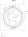
- FIG. 3 is a plan view illustrating a silicon wafer 70 after being etched.
- FIG. 4 is an enlarged plan view in which one wheel 50 is enlarged.
- the X axis is a coordinate axis parallel to a surface of the silicon wafer 70.
- the Y axis is a coordinate axis parallel to the surface of the silicon wafer 70 and orthogonal to the X axis.
- the Z axis is a coordinate axis orthogonal to the surface of the silicon wafer 70, that is, an XY plane.
- a direction parallel to the XY plane is also referred to as a plane direction
- a direction intersecting with the XY plane is also referred to as an intersecting direction.
- the silicon wafer 70 is a disk-shaped mother substrate capable of forming a plurality of the wheels 50.
- the silicon wafer 70 is an example of a plate-shaped member.
- the plurality of wheels 50 is arranged in a matrix along the X axis and the Y axis.
- Each wheel 50 is surrounded by a frame portion 55 that is continuous to a peripheral edge portion of the silicon wafer 70. That is, the frame portion 55 is disposed outside the wheel 50.
- a dimension of the silicon wafer 70 in a direction extending along the Z axis that is, a thickness of the silicon wafer 70 is approximately 100 ⁇ m to 200 ⁇ m.
- the thickness of the silicon wafer 70 corresponds to a tooth width of the wheel 50.
- a diameter of an addendum circle (not illustrated), that is, a circle passing leading ends of the teeth 51 is approximately 5 mm to 6 mm
- a tooth thickness S (see FIG. 5 ), that is, a dimension of each tooth 51 along a pitch circle P is approximately 100 ⁇ m to 200 ⁇ m.
- the tooth width, the diameter of the addendum circle, and the tooth thickness S are not limited to being within the above-described ranges, and may be outside the above-described ranges.
- the wheel 50 is coupled to the frame portion 55 with a coupling portion 56 interposed therebetween. That is, the coupling portion 56 couples the wheel 50 to the frame portion 55, and the wheel 50 is supported by the frame portion 55 via the coupling portion 56.
- the coupling portions 56 are coupled to leading end portions of two teeth 51 among the plurality of teeth 51 included in the wheel 50. In the present embodiment, an angle formed by extending directions of the two teeth 51 to which the coupling portions 56 are coupled is approximately 180°.
- FIG. 5 is an enlarged plan view illustrating the coupling portion 56.
- the coupling portion 56 extends from a leading end portion of the tooth 51 in substantially the same direction as the extending direction of the tooth 51 and reaches the frame portion 55. That is, when an end portion, of both ends of the coupling portion 56, that is coupled to the leading end portion of the tooth 51 is a first end portion 56a, and an end portion that is coupled to the frame portion 55 is a second end portion 56b, a direction D extending from the first end portion 56a toward the second end portion 56b is substantially equal to the extending direction of the tooth 51.
- the shape of the coupling portion 56 when viewed along the Z axis is a meandering shape, that is, a wavy line shape. That is, in the plan view illustrated in FIG. 5 , the coupling portion 56 extends in the direction D while alternately repeating counterclockwise bending and clockwise bending. Therefore, the shape of the coupling portion 56 can be also rephrased as a shape that is alternately bent in mutually opposite directions.
- a width A of the coupling portion 56 corresponding to a line width of the wavy line is approximately uniform as a whole in a range excluding the first end portion 56a and the second end portion 56b.
- the width A of the coupling portion 56 is approximately 30 ⁇ m and is substantially small compared to the tooth thickness S of the tooth 51.
- the first end portion 56a a narrow portion is formed. Therefore, the first end portion 56a has a small width compared to other portions of the coupling portion 56.
- the first end portion 56a is wedged and has a smaller width toward a leading end. That is, a width B of the leading end of the first end portion 56a is smaller than the width A of the coupling portion 56.
- a width C of the second end portion 56b is larger than the width A of the coupling portion 56.
- the coupling portion 56 is flexible and can be bent in a plane direction parallel to the XY plane.
- the tooth 51 of the wheel 50 can be technically flexible, but since the width A of the coupling portion 56 is substantially small compared to the tooth thickness S of the tooth 51, the coupling portion 56 is substantially flexible compared to the tooth 51.
- the width A of the coupling portion 56 is preferably as small as possible in terms of improving of the flexibility.
- the width A of the coupling portion 56 is preferably 10 ⁇ m to 50 ⁇ m, and is more preferably 20 ⁇ m to 40 ⁇ m.
- the wheel 50 in a state of being coupled to the frame portion 55 with the coupling portion 56 interposed therebetween is cut in the first end portion 56a of the coupling portion 56 so as to be separated from the silicon wafer 70. Therefore, in the wheel 50 after being separated, a cut surface 58 is formed in the leading end portion of each of the two teeth 51 that have been coupled to the coupling portions 56 (see FIG. 2 ). That is, the cut surface 58 is a surface that has been coupled to the first end portion 56a of the respective coupling portions 56.
- the cut surface 58 can project further on an outer side than is the leading end portion of the tooth 51, but as long as the projection does not come into contact with the pinion 28 of the fourth wheel 27, which is a target pinion to be meshed with, the projection does not affect the operation.
- single crystal silicon which is the material of the wheel 50, includes a plurality of crystal planes and has a property of being easily cleaved along a crystal plane. That is, single crystal silicon can be cut with a small force when being cut along a crystal plane, compared to a case of being cut along a plane other than a crystal plane. In addition, when single crystal silicon is cut along a crystal plane, spreading of a crack, generated by cutting, in a direction other than the direction of the crystal plane is suppressed. Therefore, both front and rear surfaces of the wheel 50 parallel to the XY plane and two cut surfaces 58 coupled to the coupling portions 56 are preferably crystal planes.
- FIG. 6 is a flowchart illustrating a method of manufacturing the wheel 50
- FIGS. 7 to 15 are process sectional views for explaining the method of manufacturing the wheel 50.
- the method of manufacturing the wheel 50 includes each process of steps S1 to S6. That is, the wheel 50 is manufactured through implementing of each process of steps S1 to S6 in sequence.
- Step S1 is an oxide film formation process. As illustrated in FIG. 7 , in this process, a silicon oxide film 71 is formed on one plane of the silicon wafer 70.
- the silicon wafer 70 is ground in advance to have an appropriate thickness so that the tooth width of the wheel 50 has a desired dimension, and a surface of the silicon wafer 70 is polished.
- the silicon wafer 70 has two planes, which are a first surface 70a and a second surface 70b, on the front and rear sides.
- the silicon oxide film 71 is formed on the second surface 70b.
- a chemical vapor deposition (CVD) method is used for formation of the silicon oxide film 71.
- a film thickness of the silicon oxide film 71 is not particularly limited, but is, for example, approximately 1 ⁇ m.
- the silicon oxide film 71 is formed in order to suppress penetration of a hole 70c, which is formed in an etching process in step S4 described later, through the front and rear sides.
- Step S2 is a photoresist application process. As illustrated in FIG. 8 , in this process, a resist film 72 is formed on the first surface 70a of the silicon wafer 70. First, a resin solution, in which a photosensitive resin is dissolved, is applied to the first surface 70a of the silicon wafer 70 by a spin coating method, a spray coating method, or the like. Next, the resin solution is dried to remove a solvent so as to form the resist film 72.
- the photosensitive resin either a negative or positive material may be adopted.
- Step S3 is an exposure and development process.
- an etching mask for forming the wheel 50 is formed.
- the opening portions 72a correspond to portions of silicon to be removed from the silicon wafer 70 by etching. That is, the resist film 72, in which the opening portions 72a are formed, functions as an etching mask.
- Step S4 is an etching process.
- etching through performing of etching on the silicon wafer 70 using the resist film 72 as an etching mask, shapes of the wheels 50, the frame portion 55, and the coupling portions 56 are formed.
- anisotropic etching such as deep reactive ion etching (DRIE) by inductively coupled plasma (ICP), or the like is used.
- DRIE deep reactive ion etching
- ICP inductively coupled plasma
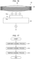
- FIG. 16 is an explanatory view illustrating a schematic configuration of an anisotropic etching apparatus 81 that performs DRIE by ICP.
- the anisotropic etching apparatus 81 includes a stage 82 and a coil 83.
- the silicon wafer 70 is mounted such that the first surface 70a, on which the resist film 72 is formed, faces the coil 83 side.
- the anisotropic etching apparatus 81 causes a high current with high frequency to flow through the coil 83 while supplying an SF 6 gas so as to generate plasma 84. Then, when the stage 82 is biased, particles of the plasma 84 are drawn onto the first surface 70a of the silicon wafer 70 from the opening portions 72a of the resist film 72.
- the silicon wafer 70 is substantially vertically etched in an intersecting direction into the shapes of the opening portions 72a from the first surface 70a side. Silicon on which etching is performed becomes SiF 4 and is removed.
- the anisotropic etching apparatus 81 cools the silicon wafer 70 from the second surface 70b side using helium gas, for example.
- the anisotropic etching apparatus 81 supplies a C 4 F 8 gas to a surface of the silicon wafer 70 so as to form a protective film 85 on a surface to which silicon is exposed. Forming of the protective film 85 is also referred to as coating.
- the anisotropic etching apparatus 81 performs etching on the silicon wafer 70 again so as to expose silicon and subsequently, as illustrated in FIG. 13 , performs coating with the protective film 85 again. In this manner, the anisotropic etching apparatus 81 repeatedly performs etching on the silicon wafer 70 and coating with the protective film 85 a plurality of times.
- This method is called a Bosch process.
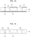
- the Bosch process as illustrated in FIG. 14 , in the silicon wafer 70, the holes 70c that reach the silicon oxide film 71 are formed in portions not covered with the resist film 72.
- the holes 70c include a gap between the wheel 50 and the frame portion 55, the opening portion 50a and the hole portion 57 formed inside the wheel 50.
- Step S5 is an oxide film removal process.
- the silicon oxide film 71 and the resist film 72 disposed on the silicon wafer 70 are removed.
- Removal of the resist film 72 can be performed by wet etching using fuming nitric acid, an organic solvent, or the like capable of dissolving and stripping the resist film 72, oxygen plasma ashing, or the like.
- an organic stripping agent is further used to remove a residue.
- Removal of the silicon oxide film 71 is performed by wet etching in which the silicon wafer 70 is immersed in a buffered hydrogen fluoride (BHF) solution. Note that removal of the silicon oxide film 71 may also be performed by reactive ion etching using a parallel plate.
- BHF buffered hydrogen fluoride
- steps S1 to S5 the plurality of wheels 50 illustrated in FIG. 3 , the frame portion 55, and the plurality of coupling portions 56 that couples the wheels 50 to the frame portion 55 are formed. That is, a series of processes including steps S1 to S5 is an outer shape formation process that forms the wheels 50, the frame portion 55, and the coupling portions 56 through performing of etching on the silicon wafer 70.
- Step S6 is a cutting process.
- the coupling portions 56 and the wheels 50 are cut.
- the operation of cutting the coupling portions 56 and the wheels 50 is performed using a tool having a fine tip such as tweezers.
- a tool having a fine tip such as tweezers.
- an operator mounts the silicon wafer 70 illustrated in FIGS. 3 and 4 on a worktable (not illustrated) and fixes the frame portion 55 to the worktable. Then, the operator inserts the tool into the opening portion 50a inside each wheel 50, and displaces the wheel 50 in the plane direction while keeping the tool in contact with the opening portion 50a. That is, the wheel 50 is displaced in the plane direction with respect to the frame portion 55 by the tool.
- each coupling portion 56 is also displaced following the displacement of the wheel 50, but since the coupling portion 56 is bent due to the flexibility, the coupling portion 56 does not break in the middle thereof.
- the first end portion 56a breaks, and the coupling portion 56 and the wheel 50 are cut.
- step S6 the wheel 50 is separated from the silicon wafer 70, as a result of which the wheel 50 is completed. That is, the wheel 50 is generated by being cut from the silicon wafer 70.
- the cut surface 58 is formed in the leading end portion of each of the two teeth 51 to which the coupling portions 56 are coupled when the coupling portions 56 are cut from the silicon wafer 70. Therefore, the plurality of teeth 51 included in the wheel 50 includes the two teeth 51 each including the cut surface 58 in the leading end portion.
- the two coupling portions 56 may be cut one by one in sequence, but the two coupling portions 56 may be cut in a single operation.
- the two coupling portions 56 can be easily cut in a single operation.
- a direction in which the wheel 50 is displaced is not limited to the plane direction, and the coupling portions 56 may be cut through displacing of the wheel 50 in an intersecting direction.
- FIG. 17 is a flowchart illustrating a method of manufacturing the mechanical timepiece 1.
- the method of manufacturing the mechanical timepiece 1 includes each process of steps S11 to S13. That is, the mechanical timepiece 1 is manufactured through implementing of each process of steps S11 to S13 in sequence.
- Step S11 is a component assembly process in which various components constituting the mechanical timepiece 1 are assembled.
- the third wheel 26, which is one component is assembled through inserting of the shaft portion 60 into the hole portion 57 of the wheel 50 that is formed by the above-described steps S1 to S6. Components other than the third wheel 26 are also assembled where necessary.
- Step S12 is a movement assembly process in which the movement 10 is assembled. This process includes a process in which various components such as the third wheel 26 are assembled in the main plate 11.
- Step S13 is a timepiece assembly process in which the mechanical timepiece 1 is assembled. This process includes a process in which the movement 10 is accommodated in a casing (not illustrated). By the above-described processes, the mechanical timepiece 1 is completed.
- each coupling portion 56 is coupled to a leading end portion of the tooth 51, even when an interval between the teeth 51 is small, the coupling portion 56 can be coupled to the wheel 50.
- the coupling portion 56 is coupled to the leading end portion of the tooth 51, it is possible to suppress influences on meshing with another wheel by the cut surface 58 that is formed after the coupling portion 56 is cut.
- the flexible coupling portion 56 when the flexible coupling portion 56 is coupled between the teeth 51, in the cutting process of step S6, the bent coupling portion 56 may come into contact with the teeth 51. In this case, the coupling portion 56 may break in the middle thereof or may damage the teeth 51. On the other hand, in the present embodiment, since the coupling portion 56 is coupled to the leading end portion of the tooth 51, breakage of the coupling portion 56 in the middle thereof or damage to the teeth 51 in the cutting process can be suppressed.
- the etching pattern becomes dense around the coupling portion 56.
- a difference in shape may be generated between the teeth 51 around the coupling portion 56 and other teeth 51.
- the coupling portion 56 is coupled to the leading end portion of a corresponding one of the teeth 51, the etching pattern being locally dense can be suppressed, and generation of a difference in shape between the teeth 51 can be suppressed.
- the coupling portion 56 since the shape of the coupling portion 56 is a wavy line shape, compared to a case in which the shape is linear, the coupling portion 56 can be greatly bent.
- a narrow portion is formed in the first end portion 56a of the coupling portion 56. That is, since the first end portion 56a is narrower than other portions of the coupling portion 56, when the coupling portion 56 and the wheel 50 are cut, cutting can be easily performed in the first end portion 56a.
- step S6 when the wheel 50 is displaced, the tool is brought into contact with the opening portion 50a without being brought into contact with the teeth 51. In this manner, since the tool is brought into contact with a portion other than the teeth 51 at the time of cutting, damage to the teeth 51 by the tool can be suppressed.
- the wheel 50 that exhibits the above-described effects can be easily formed.
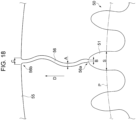
- the shape of the coupling portion 56 is a wavy line shape, but the number of waves and the amplitude of waves of the wavy line are not limited to the aspect illustrated in FIG. 5 .
- the number of waves may be less, and as illustrated in FIG. 19 , the amplitude of waves may be larger.
- the shape illustrated in FIG. 19 may be rephrased as a shape in which a linear portion is alternately bent in mutually opposite directions, or a shape in which a linear portion extending in a direction parallel to the XY plane and intersecting with the direction D extends in the direction D while being alternately bent in mutually opposite directions.
- the shape of the coupling portion 56 is not limited to a wavy line shape, and may be, as illustrated in FIG. 20 , a curved line shape, which is different from a wavy line. In this manner, the coupling portion 56 only needs to follow, to some extent, the displacement of the wheel 50 in the plane direction by the flexibility, and the shape of the coupling portion 56 is not particularly limited.
- two coupling portions 56 are coupled to each wheel 50, and the angle formed by the extending directions of the two teeth 51 to which the coupling portions 56 are coupled is approximately 180°, but the angle is not limited thereto.
- the angle formed by the extending directions of the two teeth 51 to which the coupling portions 56 are coupled may be approximately 90°, or may be another angle.
- the number of the coupling portions 56 is not limited to two, and may be one, or three or more.
- shapes or dimensions of the plurality of coupling portions 56 may be the same, or may be different.
- the direction D extending from the first end portion 56a of the coupling portion 56 toward the second end portion 56b is approximately the same direction as the extending direction of the tooth 51 to which the coupling portion 56 is coupled, but the direction D may be a direction different from the extending direction of the tooth 51.
- step S4 when the holes 70c are formed by a Bosch process, irregularities called scallops are formed on an etched surface. A process of removing the scallops may be additional executed. In this process, for example, after an oxide film having a depth of 1 ⁇ m or more is formed in the silicon wafer 70 by thermal oxidation, the silicon wafer 70 may be immersed in a BHF solution so as to perform etching on the oxide film.
- an oxidation treatment in which a silicon oxide film made of silicon dioxide (SiOz) is formed on a surface of the wheel 50, may be performed.
- SiOz silicon oxide film made of silicon dioxide
- the oxidation treatment is performed on the wheel 50, mechanical strength of the wheel 50 is improved by the silicon oxide film formed on the surface of the wheel 50 made of a material containing silicon.
- a thermal oxidation treatment that is performed at a high temperature of 1000°C or more is preferably performed.
- silicon is used as a plate-shaped member made of a brittle material, but the material of the wheel 50 is not limited to silicon.
- silicon carbide, quartz crystal, glass, sapphire, or the like may be used.
- the wheel 50 of the third wheel 26 constituting the front wheel train of the mechanical timepiece 1 is exemplified, but the structure of the wheel 50 and the method of manufacturing the wheel 50 described in the above-described embodiment are applicable to various wheels such as other wheels constituting the front wheel train and wheels constituting the rear wheel train.
- the timepiece is not limited to the mechanical timepiece 1, and may be other timepieces such as an electronic timepiece. That is, the structure of the wheel 50 and the method of manufacturing the wheel 50 described in the above-described embodiment are applicable to wheels included in an electronic timepiece, or the like.
Landscapes
- Physics & Mathematics (AREA)
- General Physics & Mathematics (AREA)
- Engineering & Computer Science (AREA)
- Manufacturing & Machinery (AREA)
- Microelectronics & Electronic Packaging (AREA)
- Optics & Photonics (AREA)
- Plasma & Fusion (AREA)
- Gears, Cams (AREA)
- Micromachines (AREA)
Abstract
A method of manufacturing a wheel includes an outer shape formation process in which etching is performed or a silicon wafer made of a brittle material to form the wheel including a plurality of teeth, a frame portion that is disposed outside the wheel, and a coupling portion that is more flexible than the teeth and couples the frame portion to a leading end portion of a corresponding one of the teeth, and a cutting process in which the coupling portion and the wheel are cut.
Description
- The present application is based on, and claims priority from
JP Application Serial Number 2023-103171, filed June 23, 2023 - The present disclosure relates to a method of manufacturing a wheel for a timepiece, a plate-shaped member, a wheel for a timepiece, and a timepiece.
- In
JP-A-2020-46348 - However, in
JP-A-2020-46348 - A method of manufacturing a wheel for a timepiece includes performing etching on a plate-shaped member made of a brittle material to form a wheel for a timepiece including a plurality of teeth, a frame portion that is disposed outside the wheel for a timepiece, and a coupling portion that is more flexible than the teeth and couples the frame portion to a leading end portion of a corresponding one of the teeth, and cutting the coupling portion and the wheel for a timepiece.
- A plate-shaped member made of a brittle material includes a wheel for a timepiece including a plurality of teeth, a frame portion that is disposed outside the wheel for a timepiece, and a coupling portion that is more flexible than the teeth and couples the frame portion to a leading end portion of a corresponding one of the teeth.
- A wheel for a timepiece generated by being cut from a plate-shaped member made of a brittle material includes a plurality of teeth, and the plurality of teeth includes a tooth that has a cut surface, in a leading end portion, that is formed when the wheel for a timepiece is cut from the plate-shaped member.
- A timepiece includes the above-described wheel for a timepiece.
-
-
FIG. 1 is a plan view of a movement of a mechanical timepiece viewed from a front side. -
FIG. 2 is a plan view illustrating a configuration of a third wheel. -
FIG. 3 is a plan view illustrating a silicon wafer after being etched. -
FIG. 4 is an enlarged plan view in which one wheel included in the silicon wafer is enlarged. -
FIG. 5 is an enlarged plan view illustrating a coupling portion. -
FIG. 6 is a flowchart illustrating a method of manufacturing a wheel. -
FIG. 7 is a process sectional view for explaining the method of manufacturing the wheel. -
FIG. 8 is a process sectional view for explaining the method of manufacturing the wheel. -
FIG. 9 is a process sectional view for explaining the method of manufacturing the wheel. -
FIG. 10 is a process sectional view for explaining the method of manufacturing the wheel. -
FIG. 11 is a process sectional view for explaining the method of manufacturing the wheel. -
FIG. 12 is a process sectional view for explaining the method of manufacturing the wheel. -
FIG. 13 is a process sectional view for explaining the method of manufacturing the wheel. -
FIG. 14 is a process sectional view for explaining the method of manufacturing the wheel. -
FIG. 15 is a process sectional view for explaining the method of manufacturing the wheel. -
FIG. 16 is an explanatory view illustrating a schematic configuration of an anisotropic etching apparatus. -
FIG. 17 is a flowchart illustrating a method of manufacturing a mechanical timepiece. -
FIG. 18 is an enlarged plan view illustrating a coupling portion according to a modification. -
FIG. 19 is an enlarged plan view illustrating a coupling portion according to a modification. -
FIG. 20 is an enlarged plan view illustrating a coupling portion according to a modification. -
FIG. 21 is an enlarged plan view in which one wheel included in a silicon wafer according to a modification is enlarged. - Hereinafter, a timepiece, a wheel for a timepiece, and a method of manufacturing the timepiece and the wheel for a timepiece of the present embodiment will be described with reference to the drawings. In the drawings referred to below, in order to show layers and members in recognizable sizes, scales of the layers and the members may be set different from actual scales.
-
FIG. 1 is a plan view of amovement 10 of amechanical timepiece 1 viewed from a front side. In the present embodiment, a rear side is a side on which a hand indicating a time is disposed, and a front side is a side on which a spring that drives the hand, and the like are disposed. A forward side of the page inFIG. 1 is a front side, and a rearward side of the page is a rear side. - The
mechanical timepiece 1 includes themovement 10 illustrated inFIG. 1 and a casing (not illustrated) that accommodates themovement 10. Themechanical timepiece 1 is an example of a timepiece. - The
movement 10 includes amain plate 11. Themain plate 11 is a plate member for supporting each component and determining a position. A dial (not illustrated) is disposed on the rear side of themain plate 11. A wheel train including a plurality of wheels is disposed on each of the front side and the rear side of themain plate 11. The wheel train disposed on the front side of themain plate 11 is also referred to as a front wheel train, and the wheel train disposed on the rear side of themain plate 11 is also referred to as a rear wheel train. - In the
main plate 11, in a direction parallel to themain plate 11 and extending toward a center from an outer edge, a windingstem guide hole 11a that guides a shaft-shaped windingstem 12 is formed. In addition, the windingstem 12 is incorporated in the windingstem guide hole 11a so as to be able to move in an axial direction and rotate around the axis. A settinglever 13, ayoke 14, a yoke spring 15, and a settinglever jumper 16 are disposed near the windingstem 12. The settinglever 13, theyoke 14, the yoke spring 15, and the settinglever jumper 16 constitute a switching mechanism that switches a transmission destination of a rotational force of the windingstem 12. - The winding
stem 12 is inserted into a windingpinion 17 that is rotatable around the same axis as the windingstem 12. In addition, in the windingstem 12, a clutch wheel (not illustrated) that is rotated together with the windingstem 12 is disposed. The clutch wheel is rotatable around the same axis as the windingstem 12 and is also movable in the axial direction of the windingstem 12 by the switching mechanism. When the windingstem 12 changes its position in the axial direction, the switching mechanism switches between a state in which the clutch wheel meshes with the windingpinion 17 and a state in which the clutch wheel does not mesh with the windingpinion 17. In addition, in themain plate 11, acrown wheel 20 that meshes with the windingpinion 17, aratchet wheel 21 that meshes with thecrown wheel 20, and abarrel wheel 22 that accommodates a spring are rotatably installed. - When the winding
stem 12 moves in the axial direction and is disposed at a first winding stem position nearest a center of themovement 10, the clutch wheel meshes with the windingpinion 17. When an operator rotates the windingstem 12 in this state, the windingpinion 17 is rotated together with the clutch wheel. Then, when the windingpinion 17 is rotated, thecrown wheel 20 is rotated. Then, when thecrown wheel 20 is rotated, theratchet wheel 21 is rotated. Furthermore, when theratchet wheel 21 is rotated, the spring accommodated in thebarrel wheel 22 is wound up. The spring is a power source for driving themovement 10. Note that when the windingstem 12 is disposed further on an outer side than is the first winding stem position, meshing of the clutch wheel with the windingpinion 17 is released, and the clutch wheel meshes with a setting wheel (not illustrated) for performing time adjustment, or the like. - On the
main plate 11, asecond wheel 25, athird wheel 26, and afourth wheel 27 are rotatably disposed. Thesecond wheel 25, thethird wheel 26, and thefourth wheel 27 each include a wheel and a pinion that integrally rotate. The above-described front wheel train is composed of thebarrel wheel 22, thesecond wheel 25, thethird wheel 26, and thefourth wheel 27. The front wheel train has a function of transmitting a rotational force of thebarrel wheel 22. In addition, on the front side of themovement 10, an escapement mechanism 30 and aspeed control mechanism 31 are disposed on themain plate 11. The escapement mechanism 30 and thespeed control mechanism 31 adjust a rotation speed of the front wheel train. - The pinion of the
second wheel 25 meshes with thebarrel wheel 22. A minute hand (not illustrated) is coupled to thesecond wheel 25. The pinion of thethird wheel 26 meshes with the wheel of thesecond wheel 25. The pinion of thefourth wheel 27 meshes with the wheel of thethird wheel 26. A second hand (not illustrated) is coupled to thefourth wheel 27. The escapement mechanism 30 is a mechanism that controls the rotation of the front wheel train. The escapement mechanism 30 includes an escape wheel 35 and a pallet fork 36. The escape wheel 35 includes a pinion that meshes with the wheel of thefourth wheel 27 and is rotated by receiving torque of thefourth wheel 27. The pallet fork 36 rotates the escape wheel 35 regularly according to the movement of thespeed control mechanism 31. Thespeed control mechanism 31 includes a balance with ahairspring 40 that swings at a fixed cycle, and the like, and adjusts the rotation speed of the escape wheel 35 so as to adjust the rotation speed of the front wheel train that meshes with the escape wheel 35. - Next, among the above-described various components, the
third wheel 26 will be described in detail.FIG. 2 is a plan view illustrating a configuration of thethird wheel 26. As illustrated inFIG. 2 , thethird wheel 26 includes awheel 50 and ashaft portion 60 serving as a rotary shaft of thewheel 50. Thewheel 50 includes anannular rim portion 52 including a plurality ofteeth 51 on an outer peripheral surface, a holdingportion 53 through which theshaft portion 60 is inserted, and a plurality ofcoupling portions 54 that radially extends from the holdingportion 53 and couples therim portion 52 to the holdingportion 53. In thewheel 50, anopening portion 50a surrounded by therim portion 52, the holdingportion 53, and twoadjacent coupling portions 54 is formed. Specifically, in thewheel 50, the same number of the openingportions 50a as the number of thecoupling portions 54 are formed in a circumferential direction. Thewheel 50 meshes with a pinion 28 (seeFIG. 1 ) included in thefourth wheel 27. Thewheel 50 is an example of a wheel for a timepiece. - In the
shaft portion 60, apinion 61 that meshes with the wheel of thesecond wheel 25 is integrally formed. Theshaft portion 60 is inserted into a hole portion 57 (seeFIG. 4 ) formed in a center of thewheel 50 and is fixed to thewheel 50. Therefore, thewheel 50 is rotated integrally with thepinion 61. - The
wheel 50 has a plate shape and has a substantially uniform thickness over the entire surface. Thewheel 50 is made of a brittle material having a crystal orientation such as single crystal silicon. The material of thewheel 50 of the present embodiment is single crystal silicon. Specifically, thewheel 50 is formed through performing of etching on a silicon wafer made of single crystal silicon. A method of manufacturing thewheel 50 will be described later. -
FIG. 3 is a plan view illustrating asilicon wafer 70 after being etched.FIG. 4 is an enlarged plan view in which onewheel 50 is enlarged. InFIGS. 3 and4 , an X axis, a Y axis, and a Z axis orthogonal to each other are illustrated. The X axis is a coordinate axis parallel to a surface of thesilicon wafer 70. The Y axis is a coordinate axis parallel to the surface of thesilicon wafer 70 and orthogonal to the X axis. The Z axis is a coordinate axis orthogonal to the surface of thesilicon wafer 70, that is, an XY plane. Hereinafter, a direction parallel to the XY plane is also referred to as a plane direction, and a direction intersecting with the XY plane is also referred to as an intersecting direction. - As illustrated in
FIG. 3 , thesilicon wafer 70 is a disk-shaped mother substrate capable of forming a plurality of thewheels 50. Thesilicon wafer 70 is an example of a plate-shaped member. In onesilicon wafer 70, the plurality ofwheels 50 is arranged in a matrix along the X axis and the Y axis. Eachwheel 50 is surrounded by aframe portion 55 that is continuous to a peripheral edge portion of thesilicon wafer 70. That is, theframe portion 55 is disposed outside thewheel 50. - In the present embodiment, a dimension of the
silicon wafer 70 in a direction extending along the Z axis, that is, a thickness of thesilicon wafer 70 is approximately 100 µm to 200 µm. The thickness of thesilicon wafer 70 corresponds to a tooth width of thewheel 50. In addition, a diameter of an addendum circle (not illustrated), that is, a circle passing leading ends of theteeth 51 is approximately 5 mm to 6 mm, and a tooth thickness S (seeFIG. 5 ), that is, a dimension of eachtooth 51 along a pitch circle P is approximately 100 µm to 200 µm. However, the tooth width, the diameter of the addendum circle, and the tooth thickness S are not limited to being within the above-described ranges, and may be outside the above-described ranges. - The
wheel 50 is coupled to theframe portion 55 with acoupling portion 56 interposed therebetween. That is, thecoupling portion 56 couples thewheel 50 to theframe portion 55, and thewheel 50 is supported by theframe portion 55 via thecoupling portion 56. Thecoupling portions 56 are coupled to leading end portions of twoteeth 51 among the plurality ofteeth 51 included in thewheel 50. In the present embodiment, an angle formed by extending directions of the twoteeth 51 to which thecoupling portions 56 are coupled is approximately 180°. -
FIG. 5 is an enlarged plan view illustrating thecoupling portion 56. As illustrated inFIG. 5 , thecoupling portion 56, as a whole, extends from a leading end portion of thetooth 51 in substantially the same direction as the extending direction of thetooth 51 and reaches theframe portion 55. That is, when an end portion, of both ends of thecoupling portion 56, that is coupled to the leading end portion of thetooth 51 is afirst end portion 56a, and an end portion that is coupled to theframe portion 55 is asecond end portion 56b, a direction D extending from thefirst end portion 56a toward thesecond end portion 56b is substantially equal to the extending direction of thetooth 51. - The shape of the
coupling portion 56 when viewed along the Z axis is a meandering shape, that is, a wavy line shape. That is, in the plan view illustrated inFIG. 5 , thecoupling portion 56 extends in the direction D while alternately repeating counterclockwise bending and clockwise bending. Therefore, the shape of thecoupling portion 56 can be also rephrased as a shape that is alternately bent in mutually opposite directions. - A width A of the
coupling portion 56 corresponding to a line width of the wavy line is approximately uniform as a whole in a range excluding thefirst end portion 56a and thesecond end portion 56b. In the present embodiment, the width A of thecoupling portion 56 is approximately 30 µm and is substantially small compared to the tooth thickness S of thetooth 51. In thefirst end portion 56a, a narrow portion is formed. Therefore, thefirst end portion 56a has a small width compared to other portions of thecoupling portion 56. Specifically, thefirst end portion 56a is wedged and has a smaller width toward a leading end. That is, a width B of the leading end of thefirst end portion 56a is smaller than the width A of thecoupling portion 56. On the other hand, a width C of thesecond end portion 56b is larger than the width A of thecoupling portion 56. - The
coupling portion 56 is flexible and can be bent in a plane direction parallel to the XY plane. Thetooth 51 of thewheel 50 can be technically flexible, but since the width A of thecoupling portion 56 is substantially small compared to the tooth thickness S of thetooth 51, thecoupling portion 56 is substantially flexible compared to thetooth 51. The width A of thecoupling portion 56 is preferably as small as possible in terms of improving of the flexibility. On the other hand, when the width A of thecoupling portion 56 is made too small, it becomes difficult to form thecoupling portion 56 by etching. Therefore, the width A of thecoupling portion 56 is preferably 10 µm to 50 µm, and is more preferably 20 µm to 40 µm. - The
wheel 50 in a state of being coupled to theframe portion 55 with thecoupling portion 56 interposed therebetween is cut in thefirst end portion 56a of thecoupling portion 56 so as to be separated from thesilicon wafer 70. Therefore, in thewheel 50 after being separated, acut surface 58 is formed in the leading end portion of each of the twoteeth 51 that have been coupled to the coupling portions 56 (seeFIG. 2 ). That is, thecut surface 58 is a surface that has been coupled to thefirst end portion 56a of therespective coupling portions 56. Thecut surface 58 can project further on an outer side than is the leading end portion of thetooth 51, but as long as the projection does not come into contact with the pinion 28 of thefourth wheel 27, which is a target pinion to be meshed with, the projection does not affect the operation. - Note that single crystal silicon, which is the material of the
wheel 50, includes a plurality of crystal planes and has a property of being easily cleaved along a crystal plane. That is, single crystal silicon can be cut with a small force when being cut along a crystal plane, compared to a case of being cut along a plane other than a crystal plane. In addition, when single crystal silicon is cut along a crystal plane, spreading of a crack, generated by cutting, in a direction other than the direction of the crystal plane is suppressed. Therefore, both front and rear surfaces of thewheel 50 parallel to the XY plane and two cutsurfaces 58 coupled to thecoupling portions 56 are preferably crystal planes. - Next, a method of manufacturing the
wheel 50 included in thethird wheel 26 will be described.FIG. 6 is a flowchart illustrating a method of manufacturing thewheel 50, andFIGS. 7 to 15 are process sectional views for explaining the method of manufacturing thewheel 50. As illustrated inFIG. 6 , the method of manufacturing thewheel 50 includes each process of steps S1 to S6. That is, thewheel 50 is manufactured through implementing of each process of steps S1 to S6 in sequence. - Step S1 is an oxide film formation process. As illustrated in
FIG. 7 , in this process, asilicon oxide film 71 is formed on one plane of thesilicon wafer 70. Thesilicon wafer 70 is ground in advance to have an appropriate thickness so that the tooth width of thewheel 50 has a desired dimension, and a surface of thesilicon wafer 70 is polished. - The
silicon wafer 70 has two planes, which are afirst surface 70a and asecond surface 70b, on the front and rear sides. In step S1, thesilicon oxide film 71 is formed on thesecond surface 70b. For formation of thesilicon oxide film 71, a chemical vapor deposition (CVD) method is used. A film thickness of thesilicon oxide film 71 is not particularly limited, but is, for example, approximately 1 µm. Thesilicon oxide film 71 is formed in order to suppress penetration of ahole 70c, which is formed in an etching process in step S4 described later, through the front and rear sides. - Step S2 is a photoresist application process. As illustrated in
FIG. 8 , in this process, a resistfilm 72 is formed on thefirst surface 70a of thesilicon wafer 70. First, a resin solution, in which a photosensitive resin is dissolved, is applied to thefirst surface 70a of thesilicon wafer 70 by a spin coating method, a spray coating method, or the like. Next, the resin solution is dried to remove a solvent so as to form the resistfilm 72. For the photosensitive resin, either a negative or positive material may be adopted. - Step S3 is an exposure and development process. In this process, an etching mask for forming the
wheel 50 is formed. First, using a photomask, in which a pattern corresponding to the plurality ofwheels 50, theframe portion 55, and a plurality of thecoupling portions 56 coupling the plurality ofwheels 50 to theframe portion 55, as illustrated inFIG. 3 , is formed, exposure is performed on the resistfilm 72. Then, after development is performed to remove unnecessary portions of the resistfilm 72, in the resistfilm 72, as illustrated inFIG. 9 , openingportions 72a corresponding to the pattern of the photomask are formed. The openingportions 72a correspond to portions of silicon to be removed from thesilicon wafer 70 by etching. That is, the resistfilm 72, in which theopening portions 72a are formed, functions as an etching mask. - Step S4 is an etching process. In this process, through performing of etching on the
silicon wafer 70 using the resistfilm 72 as an etching mask, shapes of thewheels 50, theframe portion 55, and thecoupling portions 56 are formed. For etching, for example, anisotropic etching such as deep reactive ion etching (DRIE) by inductively coupled plasma (ICP), or the like is used. -
FIG. 16 is an explanatory view illustrating a schematic configuration of ananisotropic etching apparatus 81 that performs DRIE by ICP. As illustrated inFIG. 16 , theanisotropic etching apparatus 81 includes astage 82 and acoil 83. On thestage 82, thesilicon wafer 70 is mounted such that thefirst surface 70a, on which the resistfilm 72 is formed, faces thecoil 83 side. Theanisotropic etching apparatus 81 causes a high current with high frequency to flow through thecoil 83 while supplying an SF6 gas so as to generateplasma 84. Then, when thestage 82 is biased, particles of theplasma 84 are drawn onto thefirst surface 70a of thesilicon wafer 70 from the openingportions 72a of the resistfilm 72. As a result, thesilicon wafer 70 is substantially vertically etched in an intersecting direction into the shapes of the openingportions 72a from thefirst surface 70a side. Silicon on which etching is performed becomes SiF4 and is removed. In order to prevent an excessive rise in the temperature of thesilicon wafer 70, theanisotropic etching apparatus 81 cools thesilicon wafer 70 from thesecond surface 70b side using helium gas, for example. - As illustrated in
FIG. 10 , when thesilicon wafer 70 is scraped to have a predetermined depth, as illustrated inFIG. 11 , theanisotropic etching apparatus 81 supplies a C4F8 gas to a surface of thesilicon wafer 70 so as to form aprotective film 85 on a surface to which silicon is exposed. Forming of theprotective film 85 is also referred to as coating. - Then, as illustrated in
FIG. 12 , theanisotropic etching apparatus 81 performs etching on thesilicon wafer 70 again so as to expose silicon and subsequently, as illustrated inFIG. 13 , performs coating with theprotective film 85 again. In this manner, theanisotropic etching apparatus 81 repeatedly performs etching on thesilicon wafer 70 and coating with the protective film 85 a plurality of times. This method is called a Bosch process. By the Bosch process, as illustrated inFIG. 14 , in thesilicon wafer 70, theholes 70c that reach thesilicon oxide film 71 are formed in portions not covered with the resistfilm 72. Here, theholes 70c include a gap between thewheel 50 and theframe portion 55, theopening portion 50a and thehole portion 57 formed inside thewheel 50. - Step S5 is an oxide film removal process. In this process, as illustrated in
FIG. 15 , thesilicon oxide film 71 and the resistfilm 72 disposed on thesilicon wafer 70 are removed. Removal of the resistfilm 72 can be performed by wet etching using fuming nitric acid, an organic solvent, or the like capable of dissolving and stripping the resistfilm 72, oxygen plasma ashing, or the like. In the present embodiment, after oxygen plasma ashing is performed, an organic stripping agent is further used to remove a residue. - Removal of the
silicon oxide film 71 is performed by wet etching in which thesilicon wafer 70 is immersed in a buffered hydrogen fluoride (BHF) solution. Note that removal of thesilicon oxide film 71 may also be performed by reactive ion etching using a parallel plate. - As described above, by steps S1 to S5, the plurality of
wheels 50 illustrated inFIG. 3 , theframe portion 55, and the plurality ofcoupling portions 56 that couples thewheels 50 to theframe portion 55 are formed. That is, a series of processes including steps S1 to S5 is an outer shape formation process that forms thewheels 50, theframe portion 55, and thecoupling portions 56 through performing of etching on thesilicon wafer 70. - Step S6 is a cutting process. In this process, the
coupling portions 56 and thewheels 50 are cut. The operation of cutting thecoupling portions 56 and thewheels 50 is performed using a tool having a fine tip such as tweezers. Specifically, an operator mounts thesilicon wafer 70 illustrated inFIGS. 3 and4 on a worktable (not illustrated) and fixes theframe portion 55 to the worktable. Then, the operator inserts the tool into theopening portion 50a inside eachwheel 50, and displaces thewheel 50 in the plane direction while keeping the tool in contact with theopening portion 50a. That is, thewheel 50 is displaced in the plane direction with respect to theframe portion 55 by the tool. At this time, thefirst end portion 56a of eachcoupling portion 56 is also displaced following the displacement of thewheel 50, but since thecoupling portion 56 is bent due to the flexibility, thecoupling portion 56 does not break in the middle thereof. In addition, when a force acting on thefirst end portion 56a reaches a predetermined value, thefirst end portion 56a breaks, and thecoupling portion 56 and thewheel 50 are cut. - By step S6, the
wheel 50 is separated from thesilicon wafer 70, as a result of which thewheel 50 is completed. That is, thewheel 50 is generated by being cut from thesilicon wafer 70. In addition, thecut surface 58 is formed in the leading end portion of each of the twoteeth 51 to which thecoupling portions 56 are coupled when thecoupling portions 56 are cut from thesilicon wafer 70. Therefore, the plurality ofteeth 51 included in thewheel 50 includes the twoteeth 51 each including thecut surface 58 in the leading end portion. - Note that the two
coupling portions 56 may be cut one by one in sequence, but the twocoupling portions 56 may be cut in a single operation. For example, when a shaft is inserted into thehole portion 57 at the center of thewheel 50 so that thewheel 50 is turned around the shaft, the twocoupling portions 56 can be easily cut in a single operation. In addition, a direction in which thewheel 50 is displaced is not limited to the plane direction, and thecoupling portions 56 may be cut through displacing of thewheel 50 in an intersecting direction. - Next, a method of manufacturing the
mechanical timepiece 1 will be described.FIG. 17 is a flowchart illustrating a method of manufacturing themechanical timepiece 1. As illustrated inFIG. 17 , the method of manufacturing themechanical timepiece 1 includes each process of steps S11 to S13. That is, themechanical timepiece 1 is manufactured through implementing of each process of steps S11 to S13 in sequence. - Step S11 is a component assembly process in which various components constituting the
mechanical timepiece 1 are assembled. For example, thethird wheel 26, which is one component, is assembled through inserting of theshaft portion 60 into thehole portion 57 of thewheel 50 that is formed by the above-described steps S1 to S6. Components other than thethird wheel 26 are also assembled where necessary. - Step S12 is a movement assembly process in which the
movement 10 is assembled. This process includes a process in which various components such as thethird wheel 26 are assembled in themain plate 11. - Step S13 is a timepiece assembly process in which the
mechanical timepiece 1 is assembled. This process includes a process in which themovement 10 is accommodated in a casing (not illustrated). By the above-described processes, themechanical timepiece 1 is completed. - As described above, according to the
wheel 50, and the method of manufacturing thewheel 50 of the present embodiment, the following effects can be obtained. - According to the present embodiment, since each
coupling portion 56 is coupled to a leading end portion of thetooth 51, even when an interval between theteeth 51 is small, thecoupling portion 56 can be coupled to thewheel 50. In addition, since thecoupling portion 56 is coupled to the leading end portion of thetooth 51, it is possible to suppress influences on meshing with another wheel by thecut surface 58 that is formed after thecoupling portion 56 is cut. - Note that when the
flexible coupling portion 56 is coupled between theteeth 51, in the cutting process of step S6, thebent coupling portion 56 may come into contact with theteeth 51. In this case, thecoupling portion 56 may break in the middle thereof or may damage theteeth 51. On the other hand, in the present embodiment, since thecoupling portion 56 is coupled to the leading end portion of thetooth 51, breakage of thecoupling portion 56 in the middle thereof or damage to theteeth 51 in the cutting process can be suppressed. - In addition, when the
coupling portion 56 is coupled between theteeth 51, the etching pattern becomes dense around thecoupling portion 56. As a result, due to a micro-loading effect, a difference in shape may be generated between theteeth 51 around thecoupling portion 56 andother teeth 51. On the other hand, in the present embodiment, since thecoupling portion 56 is coupled to the leading end portion of a corresponding one of theteeth 51, the etching pattern being locally dense can be suppressed, and generation of a difference in shape between theteeth 51 can be suppressed. - In addition, according to the present embodiment, since the shape of the
coupling portion 56 is a wavy line shape, compared to a case in which the shape is linear, thecoupling portion 56 can be greatly bent. - In addition, according to the present embodiment, a narrow portion is formed in the
first end portion 56a of thecoupling portion 56. That is, since thefirst end portion 56a is narrower than other portions of thecoupling portion 56, when thecoupling portion 56 and thewheel 50 are cut, cutting can be easily performed in thefirst end portion 56a. - In addition, according to the present embodiment, in the cutting process of step S6, when the
wheel 50 is displaced, the tool is brought into contact with theopening portion 50a without being brought into contact with theteeth 51. In this manner, since the tool is brought into contact with a portion other than theteeth 51 at the time of cutting, damage to theteeth 51 by the tool can be suppressed. - In addition, according to the
silicon wafer 70 in which outer shapes of thewheel 50, theframe portion 55, and thecoupling portion 56 are formed after passing through the outer shape formation process of the present embodiment, thewheel 50 that exhibits the above-described effects can be easily formed. - In addition, according to the
mechanical timepiece 1 of the present embodiment, since thewheel 50 that exhibits the above-described effects is used, stable operation can be realized. - The above-described embodiment may be modified as follows.
- In the above-described embodiment, the shape of the
coupling portion 56 is a wavy line shape, but the number of waves and the amplitude of waves of the wavy line are not limited to the aspect illustrated inFIG. 5 . For example, as illustrated inFIG. 18 , the number of waves may be less, and as illustrated inFIG. 19 , the amplitude of waves may be larger. Note that the shape illustrated inFIG. 19 may be rephrased as a shape in which a linear portion is alternately bent in mutually opposite directions, or a shape in which a linear portion extending in a direction parallel to the XY plane and intersecting with the direction D extends in the direction D while being alternately bent in mutually opposite directions. In addition, the shape of thecoupling portion 56 is not limited to a wavy line shape, and may be, as illustrated inFIG. 20 , a curved line shape, which is different from a wavy line. In this manner, thecoupling portion 56 only needs to follow, to some extent, the displacement of thewheel 50 in the plane direction by the flexibility, and the shape of thecoupling portion 56 is not particularly limited. - In the above-described embodiment, two
coupling portions 56 are coupled to eachwheel 50, and the angle formed by the extending directions of the twoteeth 51 to which thecoupling portions 56 are coupled is approximately 180°, but the angle is not limited thereto. For example, as illustrated inFIG. 21 , the angle formed by the extending directions of the twoteeth 51 to which thecoupling portions 56 are coupled may be approximately 90°, or may be another angle. In addition, the number of thecoupling portions 56 is not limited to two, and may be one, or three or more. In addition, in a configuration in which a plurality of thecoupling portions 56 is coupled to onewheel 50, shapes or dimensions of the plurality ofcoupling portions 56 may be the same, or may be different. - In the above-described embodiment, the direction D extending from the
first end portion 56a of thecoupling portion 56 toward thesecond end portion 56b is approximately the same direction as the extending direction of thetooth 51 to which thecoupling portion 56 is coupled, but the direction D may be a direction different from the extending direction of thetooth 51. - In the above-described embodiment, in the etching process of step S4, when the
holes 70c are formed by a Bosch process, irregularities called scallops are formed on an etched surface. A process of removing the scallops may be additional executed. In this process, for example, after an oxide film having a depth of 1 µm or more is formed in thesilicon wafer 70 by thermal oxidation, thesilicon wafer 70 may be immersed in a BHF solution so as to perform etching on the oxide film. - In the above-described embodiment, in the component assembly process of step S11, after the
shaft portion 60 is inserted into thewheel 50, an oxidation treatment, in which a silicon oxide film made of silicon dioxide (SiOz) is formed on a surface of thewheel 50, may be performed. When the oxidation treatment is performed on thewheel 50, mechanical strength of thewheel 50 is improved by the silicon oxide film formed on the surface of thewheel 50 made of a material containing silicon. When the oxidation treatment is performed, for example, a thermal oxidation treatment that is performed at a high temperature of 1000°C or more is preferably performed. - In the above-described embodiment, as the material of the
wheel 50, silicon is used as a plate-shaped member made of a brittle material, but the material of thewheel 50 is not limited to silicon. For example, silicon carbide, quartz crystal, glass, sapphire, or the like may be used. - In the above-described embodiment, the
wheel 50 of thethird wheel 26 constituting the front wheel train of themechanical timepiece 1 is exemplified, but the structure of thewheel 50 and the method of manufacturing thewheel 50 described in the above-described embodiment are applicable to various wheels such as other wheels constituting the front wheel train and wheels constituting the rear wheel train. In addition, the timepiece is not limited to themechanical timepiece 1, and may be other timepieces such as an electronic timepiece. That is, the structure of thewheel 50 and the method of manufacturing thewheel 50 described in the above-described embodiment are applicable to wheels included in an electronic timepiece, or the like.
Claims (9)
- A method of manufacturing a wheel for a timepiece comprising:performing etching on a plate-shaped member made of a brittle material to form a wheel for a timepiece including a plurality of teeth, a frame portion that is disposed outside the wheel for a timepiece, and a coupling portion that is more flexible than the teeth and couples the frame portion to a leading end portion of a corresponding one of the teeth; andcutting the coupling portion and the wheel for a timepiece.
- The method of manufacturing a wheel for a timepiece according to claim 1, wherein the coupling portion has a width that is smaller than a tooth thickness of the tooth and has a curved line shape.
- The method of manufacturing a wheel for a timepiece according to claim 1, wherein the coupling portion has a width that is smaller than a tooth thickness of the tooth and has a wavy line shape.
- The method of manufacturing a wheel for a timepiece according to claim 1, wherein the coupling portion has a width that is smaller than a tooth thickness of the tooth and has a shape in which a linear portion is alternately bent in mutually opposite directions.
- The method of manufacturing a wheel for a timepiece according to claim 1, wherein the coupling portion has a narrow portion in an end portion that is coupled to the leading end portion of the tooth.
- The method of manufacturing a wheel for a timepiece according to claim 1, whereinthe cutting the coupling portion and the wheel for a timepiece includes cutting through displacing of the wheel for a timepiece with respect to the frame portion by a tool, andthe tool comes into contact with a portion other than the teeth of the wheel for a timepiece.
- A plate-shaped member made of a brittle material comprising:a wheel for a timepiece including a plurality of teeth;a frame portion that is disposed outside the wheel for a timepiece; anda coupling portion that is more flexible than the teeth and couples the frame portion to a leading end portion of a corresponding one of the teeth.
- A wheel for a timepiece generated by being cut from a plate-shaped member made of a brittle material, the wheel for a timepiece comprising:a plurality of teeth, whereinthe plurality of teeth includes a tooth that has a cut surface, in a leading end portion, that is formed when the wheel for a timepiece is cut from the plate-shaped member.
- A timepiece comprising:
the wheel for a timepiece according to claim 8.
Applications Claiming Priority (1)
| Application Number | Priority Date | Filing Date | Title |
|---|---|---|---|
| JP2023103171A JP2025002811A (en) | 2023-06-23 | 2023-06-23 | Manufacturing method for a timepiece gear, plate-shaped member, timepiece gear, and timepiece |
Publications (1)
| Publication Number | Publication Date |
|---|---|
| EP4481506A1 true EP4481506A1 (en) | 2024-12-25 |
Family
ID=91663870
Family Applications (1)
| Application Number | Title | Priority Date | Filing Date |
|---|---|---|---|
| EP24183616.2A Pending EP4481506A1 (en) | 2023-06-23 | 2024-06-21 | Method of manufacturing wheel for timepiece, plate-shaped member, wheel for timepiece, and timepiece |
Country Status (4)
| Country | Link |
|---|---|
| US (1) | US20240427289A1 (en) |
| EP (1) | EP4481506A1 (en) |
| JP (1) | JP2025002811A (en) |
| CN (1) | CN119179256A (en) |
Citations (4)
| Publication number | Priority date | Publication date | Assignee | Title |
|---|---|---|---|---|
| US8354032B2 (en) * | 2008-07-10 | 2013-01-15 | The Swatch Group Research And Development Ltd | Method of manufacturing a micromechanical part |
| US20150346686A1 (en) * | 2014-06-03 | 2015-12-03 | Nivarox-Far S.A. | Timepiece component based on photostructurable glass |
| JP2020046348A (en) | 2018-09-20 | 2020-03-26 | セイコーエプソン株式会社 | Watch parts manufacturing method |
| JP2023103171A (en) | 2022-01-13 | 2023-07-26 | 信越化学工業株式会社 | Thermosetting maleimide resin composition, slurry, film, prepreg, laminate, and printed wiring board |
Family Cites Families (6)
| Publication number | Priority date | Publication date | Assignee | Title |
|---|---|---|---|---|
| EP1555584A1 (en) * | 2004-01-13 | 2005-07-20 | Rolex S.A. | Toothed wheel for the removal of play, gear, and the use of this gear |
| EP1722281A1 (en) * | 2005-05-12 | 2006-11-15 | ETA SA Manufacture Horlogère Suisse | Analogue indicating organ in crystalline material, timepiece provided with such an indicating organ, and manufacturing method thereof |
| EP2145856B1 (en) * | 2008-07-10 | 2014-03-12 | The Swatch Group Research and Development Ltd. | Method of manufacturing a micromechanical part |
| EP2189854A1 (en) * | 2008-11-21 | 2010-05-26 | Nivarox-FAR S.A. | Method for manufacturing a micromechanical part |
| EP2596406B1 (en) * | 2010-07-19 | 2019-03-27 | Nivarox-FAR S.A. | Oscillating mechanism with elastic pivot and mobile for the transmission of energy |
| JP5447900B1 (en) * | 2012-08-30 | 2014-03-19 | カシオ計算機株式会社 | Guidelines |
-
2023
- 2023-06-23 JP JP2023103171A patent/JP2025002811A/en active Pending
-
2024
- 2024-06-21 EP EP24183616.2A patent/EP4481506A1/en active Pending
- 2024-06-21 US US18/750,136 patent/US20240427289A1/en active Pending
- 2024-06-21 CN CN202410808936.0A patent/CN119179256A/en active Pending
Patent Citations (4)
| Publication number | Priority date | Publication date | Assignee | Title |
|---|---|---|---|---|
| US8354032B2 (en) * | 2008-07-10 | 2013-01-15 | The Swatch Group Research And Development Ltd | Method of manufacturing a micromechanical part |
| US20150346686A1 (en) * | 2014-06-03 | 2015-12-03 | Nivarox-Far S.A. | Timepiece component based on photostructurable glass |
| JP2020046348A (en) | 2018-09-20 | 2020-03-26 | セイコーエプソン株式会社 | Watch parts manufacturing method |
| JP2023103171A (en) | 2022-01-13 | 2023-07-26 | 信越化学工業株式会社 | Thermosetting maleimide resin composition, slurry, film, prepreg, laminate, and printed wiring board |
Also Published As
| Publication number | Publication date |
|---|---|
| JP2025002811A (en) | 2025-01-09 |
| US20240427289A1 (en) | 2024-12-26 |
| CN119179256A (en) | 2024-12-24 |
Similar Documents
| Publication | Publication Date | Title |
|---|---|---|
| JP6736365B2 (en) | Manufacturing method of watch parts | |
| EP3327514A2 (en) | Mechanical component, timepiece, manufacturing method of mechanical component, and manufacturing method of timepiece | |
| WO2016093354A1 (en) | Timepiece component and method for manufacturing timepiece component | |
| US10747177B2 (en) | Mechanical component, timepiece, and manufacturing method of mechanical component | |
| US12615026B2 (en) | Method for manufacturing vibration element | |
| CN111090229A (en) | Timepiece component and timepiece | |
| US20240427289A1 (en) | Method Of Manufacturing Wheel For Timepiece, Plate-Shaped Member, Wheel For Timepiece, And Timepiece | |
| JP2018194381A (en) | Manufacturing method of machine parts, watches and machine parts | |
| JP7087873B2 (en) | How to make watch parts | |
| JP2022168218A (en) | ankles, movements and watches | |
| CN115280247A (en) | Method for manufacturing a silicon timepiece component | |
| JP2023065838A (en) | Vibration element manufacturing method | |
| JP4936530B2 (en) | Manufacturing method of three-dimensional photonic crystal | |
| US20230188109A1 (en) | Method For Manufacturing Vibrator Element | |
| JP2010183208A (en) | Wet etching method and method for processing tuning fork type piezoelectric element strip | |
| JP5165855B2 (en) | Piezoelectric element forming method | |
| JP5377152B2 (en) | Quartz crystal resonator and crystal resonator manufacturing method | |
| JP6831025B2 (en) | Hairspring | |
| JP5162387B2 (en) | Method for manufacturing piezoelectric vibrating piece | |
| JP5045829B2 (en) | Quartz piece aggregate and quartz crystal resonator | |
| JP2006186847A (en) | Quartz piece aggregate and method for manufacturing the same, photomask, and quartz crystal resonator | |
| US20200041959A1 (en) | Watch Component, Movement, Watch And Method For Manufacturing Watch Component | |
| JP3809112B2 (en) | Manufacturing method of tuning fork vibrator | |
| JP4498004B2 (en) | Manufacturing method of crystal unit | |
| JP4969776B2 (en) | Quartz device manufacturing method |
Legal Events
| Date | Code | Title | Description |
|---|---|---|---|
| PUAI | Public reference made under article 153(3) epc to a published international application that has entered the european phase |
Free format text: ORIGINAL CODE: 0009012 |
|
| STAA | Information on the status of an ep patent application or granted ep patent |
Free format text: STATUS: THE APPLICATION HAS BEEN PUBLISHED |
|
| AK | Designated contracting states |
Kind code of ref document: A1 Designated state(s): AL AT BE BG CH CY CZ DE DK EE ES FI FR GB GR HR HU IE IS IT LI LT LU LV MC ME MK MT NL NO PL PT RO RS SE SI SK SM TR |
|
| STAA | Information on the status of an ep patent application or granted ep patent |
Free format text: STATUS: REQUEST FOR EXAMINATION WAS MADE |
|
| 17P | Request for examination filed |
Effective date: 20250306 |